Embed Size (px)
Citation preview

Experion PKSRelease 520
System Administration GuideEPDOC-X139-en-520A
June 2021

DISCLAIMERThis document contains Honeywell proprietary information. Information contained herein is to be used solely for the purpose submitted, and no part of this document or its contents shall be reproduced, published, or disclosed to a third party without the express permission of Honeywell International Sàrl.
While this information is presented in good faith and believed to be accurate, Honeywell disclaims the implied warranties of merchantability and fitness for a purpose and makes no express warranties except as may be stated in its written agreement with and for its customer.
In no event is Honeywell liable to anyone for any direct, special, or consequential damages. The information and specifications in this document are subject to change without notice.
Copyright 2021 - Honeywell International Sàrl
2
3
CONTENTSContents 3
Chapter 1 - About this guide 9Before reading this guide 10
Post-modification checklist 10
Chapter 2 - Administering users 11Windows user accounts 11
Users and groups 11
Passwords administration 12
Deleting a user 13
Experion Operator accounts 13
Control Builder client licenses 13
Chapter 3 - Administering displays 15
Chapter 4 - Changing service account passwords 17Service account scope types 19
Changing passwords for single-machine scope accounts 22
Changing passwords for multi-machine scope accounts 23
Preparing to change passwords for system-wide scope accounts 24
Considerations for the LocalCommServer account 26
Changing passwords for system-wide scope accounts 27
Chapter 5 - Changing DSA Advanced Security accounts passwords 33
Chapter 6 - Windows mngr account and Experion services and processes 35The mngr password and OPC Classic clients 35
The mngr password and ODBC Data Exchange security settings 35
The mngr password and print settings for alarms, events, and reports 35
Chapter 7 - Restricting access to operating systems and non-Station software37
Contents
Chapter 8 - About the system time and time zone 39
Chapter 9 - Restoring server B from a hardware failure or corrupted database 41
Chapter 10 - Creating new operating system virtual machines and templates 43Preparing partition replacement virtual hard disks 44
Creating the partition virtual hard disk 44
Creating the master partition virtual hard disk 46
Creating a virtual machine 47
Installing the Windows operating system using Microsoft media 50
Installing the Windows operating system using the Experion System Initialization media 51
Identifying the operating system and template requirements 52
Creating the Utility virtual hard disk 52
Creating the Experion System Initialization media configuration files for operating system only installations 54
Preparing the Utility virtual hard disk to include third-party applications 57
Creating the master Utility virtual hard disk 58
Starting the Experion System Initialization media installation 59
Installing VMware Tools for a non-Experion Node 61
Configuring the Windows operating system 62
Enabling hardware acceleration 62
Completing the node installation 63
Creating operating system virtual machine templates 65
Chapter 11 - Managing server licenses 69Viewing a server license 70
Exporting server licenses 70
Changing or comparing the Experion license 71
Chapter 12 - System administration of the virtualization environment 73Configuring the virtual machine load order 74
4
Contents
5
About starting and shutting down virtual machines 76
About suspending and resuming virtual machines 77
About snapshots 79
Preparing Experion nodes for snapshots including virtual machine memory 81
Changing virtual machine settings 85
Increasing the virtual hard disk size 85
Monitoring the virtualization environment 86
About resource usage 86
About system status 90
Monitoring the virtualization hardware using Dell OpenManage Server Administrator 92
Monitoring the virtualization infrastructure from Station 92
Using vMotion in the Experion virtualization environment 94
Shared storage maintenance 95
Moving a USB security device to a new ESXi host 96
Chapter 13 - Tuning system performance 99Specialized terms 100
Network layers 100
Control network (level 1) 101
Supervisory network (level 2) 102
Application network (level 3) 102
Business network (level 4, not shown) 102
Tuning the Windows operating system 103
Setting the processor scheduling 103
Optimizing the server's hard disk performance 104
Fixing file system errors 104
Defragmenting the hard disk 105
Contents
Optimizing the server's memory usage 107
Viewing memory usage 107
Increase memory to reduce paging 107
Adjusting the pagefile size 108
Network performance 109
Network traffic 110
Adjusting bindings and disabling protocols on standard networks 110
Special considerations for Fault Tolerant Ethernet/EHG networks 111
Adjusting the TCP/IP and NetBIOS binding order 111
Adjusting the NetBios protocol settings 112
Setting the link speed 112
Other network service optimizations 112
Optimizing other computer settings 113
Optimizing file sharing 113
Optimizing video settings 113
Optimizing system usage 114
Optimizing topology-related settings 115
Optimizing the scanning load 116
Guidelines for scan optimization 116
Checking the health of the scanning subsystem 118
Optimizing a controller's scanning packets 118
Importing the scan list into a spreadsheet 119
Manipulating and analyzing the spreadsheet 119
Monitoring the system 120
Assessing the need for hardware upgrades 120
Using Dell OpenManage 120
Monitoring performance 121
Configuring the Performance Monitor 122
Interpreting the performance counter values 127
6
Contents

7
Monitoring System Health 128
About System Health Monitoring 128
System Health Monitoring considerations 129
Modifying System Health rules files 129
Appendix A - Network ports used by Experion 131
Notices 139
Contents

8
Contents
CHAPTER
1 ABOUT THIS GUIDE
This guide is intended primarily for system administrators who are responsible for the administration and maintenance of the Experion Server software and related Windows operating system.
Revision history
Revision Date Description
A June 2021 Initial release of document.
How to use this guide
This guide includes basic information on Windows system administration features and discusses how to:
Task Go to
Administer users, changing mngr password, setting the system time and time zone.
System administration
Restricting access to the operating system, Station, and non-Station software.
"Restricting access to operating systems and non-Station software" on page 37
Tuning system performance and performance monitoring.
"Tuning system performance" on page 99
For more information about:
n Installing the system, see the Software Installation User's Guide.
n Configuring Experion after installation, see the Server and Client Configuration Guide.
9
n Configuring Windows domain controllers or Windows workgroups, see the Windows Domain and Workgroups Implementation GuideWindows Domain and Workgroups Planning Guide.
n Starting up and shutting down Experion, see the Startup and Shutdown Guide.
n Installing Wyse thin client software, see the Wyse Z90DE7 Thin Client Remote Peripheral Solution Installation Instructions.
Before reading this guideBefore using this guide for administration and maintenance of your Experion server, you need to:
n Understand basic Experion concepts such as 'channel,' 'controller,' 'point,' and 'Station,' as explained in the Overview.
n Install the Experion and third-party software as described in the SoftwareInstallation User's Guide.
Prerequisite skills
This guide assumes that you have a basic knowledge of the hardware you are using, that is, the computers, printers, network components.
It also assumes that you have a basic familiarity with the Microsoft Windows operating systems that you are using.
Post-modification checklistEvery time you make a change to your system (even if the change is seemingly minor), you should perform the appropriate post-modification tasks, as specified in the following table
Task Done?
If you have upgraded an existing application (including Experion) or added a new application, defragment the server's hard disk. For more information, see "Defragmenting the hard disk" on page 105.
Back up your system. This includes creating an image of the server's hard disk. For more information, see the Backup and Restore Guide.
10
Chapter 1 - About this guide
CHAPTER
2 ADMINISTERING USERS
The tasks you need to perform to administer users might include:
n Creating Windows user accounts n Adding user accounts to groups n Deleting Windows user accounts n Creating Experion Operator accounts n Changing passwords n Viewing active Control Builder clients
Windows user accountsTo enable your users to have access to Experion they must be able to log on to the computers running the Experion software. To enable this you create Windows user accounts.
The way you create Windows user accounts depends on your environment.
If your site is set up in a domain environment, you create user accounts using the Active Directory Users and Computers tool. If your site is set up in a workgroup environment, you create user accounts locally using the Computer Management tool on each computer that a user needs to log on to.
See the Microsoft Windows documentation for specific procedures on how to create user accounts.
Users and groupsUsers inherit the rights of the groups to which they belong. For example, every member of the Product Administrator group inherits all the rights assigned to the Product Administrator group.
There are several groups that are created when you install Experion. You can use Computer Management to see a description of each local group.
If you have a domain environment, you add users to global groups.
The particular group to which you add a user depends on the type of rights the user needs.
11
If the type of user is an operator, add this user to the Users group. Users belonging to this group can run certified applications, for example, Station. They cannot perform any administrative functions.
If you want to further restrict the access of an operator, you can set up the computer so that the operator only has access to Station.
If the type of user requires Windows administrator privileges, add this user to the Windows Administrators group. Users belonging to this group can use all installed applications and carry out Windows administrative functions.
If the type of user requires Experion administrator privileges, add this user to the Product Administrator group. Users belonging to this group can use all installed applications and carry out Experion administrative functions.
For information about adding a user to a group, see the Windows online help.
Passwords administrationIf you have administrator privileges you can change any user's password. For example, you might need to reset the password for a user who has forgotten their password.
If you have domain accounts, you use the Active Directory Users and Computers tool to change a user's password.
If you have local accounts, you use Computer Management to change a user's password.
If your site uses integrated accounts, see the section on changing passwords for integrated accounts in the security section of the Server and Client Configuration Guide.
Changing the password for the mngr account has implications for other Experion services that also use the mngr account. If you change the password for the mngr account, you must change the password for the mngr account on all computers that contain the mngr account.
12
Chapter 2 - Administering users
13
Deleting a userCAUTION: Do not delete the local Windows mngr account. On the Experion server this account is the Experion system account. If you delete a Windows account (or group) which has been granted access to certain resources (for example, files), then access to those resources through the deleted account is lost, even if you recreate another Windows account with the same name.
Experion Operator accountsAfter you create the required Windows user accounts, if your system uses operator-based security, you need to create operator accounts.
For details on creating operator accounts see the 'Operator-based security configuration checklist' topic in the 'Configuring system security' section of the Server and Client Configuration Guide.
Control Builder client licensesThe Server License Details display provides information about the number of licenses you have for the Experion PKS Engineering Tools, including Control Builder.
The Active Users information provided enables you to see who is using the clients licenses, so that you can ask that a client be released so that it can be used by another user.
To view the currently active users of your Control Builder clients and request that they give up their use of the client:
1. Choose Configure>Server License Details.The Server License Details display appears.
2. Click Engineering Tools to view the number of Control Builder Clients available for your Experion PKS license.
3. Click Active Users to view the identity of the people in your organization currently using one of the available Control Builder clients.
Chapter 2 - Administering users

NOTE: Recipe Builder uses the same license as Control Builder. Active users of Recipe Builder will therefore be included in the Active Users list of Control Builder clients.
4. Contact one or more of the current users and request that they close their instance of Control Builder.
5. Refresh the Engineering Tools tab of the Server License Details display to see the updated list of active users.
ATTENTION: After a change in time zone, the Active User's list retains the old time zone details, which could potentially lead to a loss of view for current Control Builder Client users. To ensure that the time zone details are correct, restart Station.
14
Chapter 2 - Administering users
CHAPTER
3 ADMINISTERING DISPLAYS
The Display Repository is a version control repository for your Experion custom displays.
There are a number of tasks that can only be performed by the Product Administrator in an organization with regard to the Display Repository. This section explains those tasks.
To create or delete a Display Repository
1. From the Configuration Explorer, choose Displays to view the Displays task lists.
2. From the Administer Display Repository task group, choose Create display repository, or Delete display repository.See the HMIWeb Display Building Guide for information about working with the Display Repository.
To discard checkouts from a Display Repository
1. From the Configuration Explorer, choose Displays to view the Displays task list.
2. From the Administer Display Repository task group, choose Discard checkouts.A list of check outs for all system users appears, enabling you to discard any as required. This action may be required if someone has left your organization, for example. See the HMIWeb Display Building Guide for information about working with the Display Repository.
To backup or restore a Display Repository
1. From the Configuration Explorer, choose Displays to view the Displays task list.
2. From the Administer Display Repository task group, choose Backup display repository, or Restore display repository.To backup or restore a Display Repository you must first log into the server hosting that repository.
15

See the HMIWeb Display Building Guide for information about working with the Display Repository.
To lock or unlock a Display Repository (maintenance mode)
1. From the Configuration Explorer, choose Displays to view the Displays task list.
2. From the Administer Display Repository task group, choose Lock display repository, or Unlock display repository.See the HMIWeb Display Building Guide for information about working with the Display Repository.
16
Chapter 3 - Administering displays
CHAPTER
4 CHANGING SERVICE ACCOUNT PASSWORDS
Overview
This section guides you in developing a process to change the password on the Windows accounts that Experion uses for various non-interactive services and DCOM objects across multiple nodes. It highlights limitations and suggests various paths to achieve an appropriate outcome for your system. There is no one method that can be used by all systems, so use this section as a starting point to develop your own procedure.
Although the main focus of this section is on the Windows mngr account, other accounts used by Experion Services and DCOM objects are also mentioned.
Honeywell–created accounts for non-interactive services
Experion uses several Honeywell–created accounts for non-interactive services on Experion nodes.
These accounts are:
n Mngr n LocalComServer n ExpSQLSvc n ExpSQLAgtSvc n StandardAccessAdmin n SecureCommSvc
To help maintain a secure environment, or if your company has such a policy, you might periodically need to change the passwords on these accounts.
If you change the password on one of these accounts using the standard Microsoft tools, "Server Manager" in Windows Server 2008 and "Computer Management" in Windows 7, the configuration for associated Services and/or DCOM objects configured to launch as one of these accounts will not be updated and hence these services or objects will not start after the next reboot or restart.
17
Honeywell provides a utility, PwdUtil, that can help with this issue. The utility changes the password on the specified account and modifies any dependent services or DCOM objects. Once the machine restarts, all the dependant services and DCOM objects use the account’s new password.
However, some of the accounts listed above are required to have a common password on multiple nodes, and the PwdUtil utility does not provide explicit support to coordinate this. You need to manage this effort yourself. This has typically resulted in:
n The service accounts never having their password changed. n The service accounts only having their password changed when
all nodes can be taken offline (for example, at a time of plant wide shutdown).
n Plants experimenting with an off–process system to come up with a strategy for changing the service account passwords for their online systems.
This section discusses the implications of changing the various accounts, what the effect will be of doing so on various nodes, and highlight any limitations on functionality at various points. From this information, you will be better able to create a policy and procedure for changing the service account passwords at your site. This section also includes some sample procedures and scenarios for changing passwords across some sample systems.
Why use local accounts instead of domain accounts?
There are several reasons to use local accounts in preference to domain accounts. Some of these reasons are:
n Experion can be installed in Workgroup environments where no domain exists, so a non-domain accounts model would be required anyway.
n Local accounts ensure that Services/DCOM objects can start even if Domain is offline; this helps prevent your system from relying on cached credentials to startup.
n Even with a domain account, the Services/DCOM objects still need to be changed on all nodes. Using a domain account may make it more complex to sequence the change.
n Local accounts simplify the installation.
18
Chapter 4 - Changing service account passwords
19
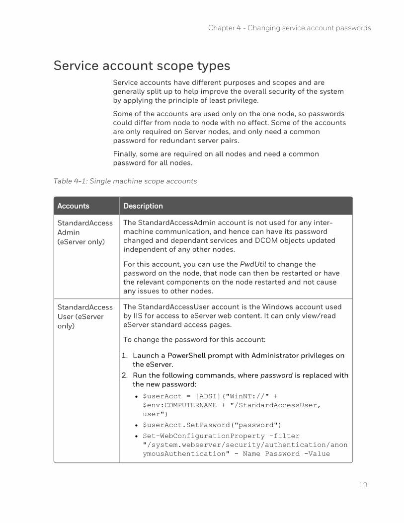
Service account scope typesService accounts have different purposes and scopes and are generally split up to help improve the overall security of the system by applying the principle of least privilege.
Some of the accounts are used only on the one node, so passwords could differ from node to node with no effect. Some of the accounts are only required on Server nodes, and only need a common password for redundant server pairs.
Finally, some are required on all nodes and need a common password for all nodes.
Table 4-1: Single machine scope accounts
Accounts Description
StandardAccessAdmin(eServer only)
The StandardAccessAdmin account is not used for any inter-machine communication, and hence can have its password changed and dependant services and DCOM objects updated independent of any other nodes.
For this account, you can use the PwdUtil to change the password on the node, that node can then be restarted or have the relevant components on the node restarted and not cause any issues to other nodes.
StandardAccessUser (eServer only)
The StandardAccessUser account is the Windows account used by IIS for access to eServer web content. It can only view/read eServer standard access pages.
To change the password for this account:
1. Launch a PowerShell prompt with Administrator privileges on the eServer.
2. Run the following commands, where password is replaced with the new password:
l $userAcct = [ADSI]("WinNT://" + $env:COMPUTERNAME + "/StandardAccessUser, user")
l $userAcct.SetPasword("password")
l Set-WebConfigurationProperty -filter "/system.webserver/security/authentication/anonymousAuthentication" - Name Password -Value
Chapter 4 - Changing service account passwords
Accounts Description
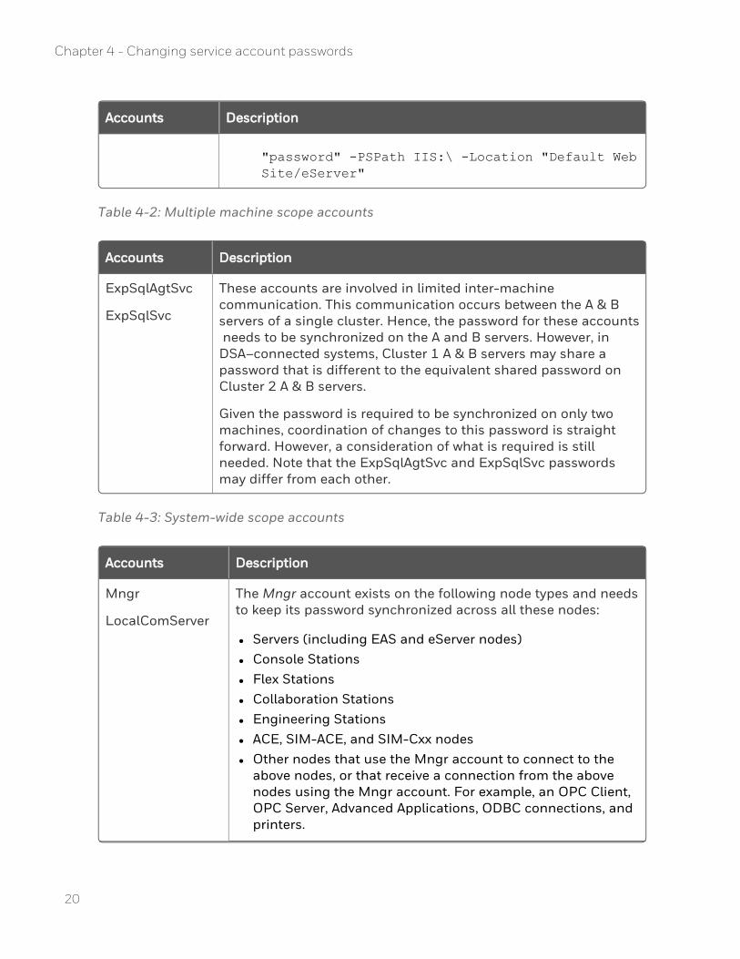
"password" -PSPath IIS:\ -Location "Default Web Site/eServer"
Table 4-2: Multiple machine scope accounts
Accounts Description
ExpSqlAgtSvc
ExpSqlSvc
These accounts are involved in limited inter-machine communication. This communication occurs between the A & B servers of a single cluster. Hence, the password for these accounts needs to be synchronized on the A and B servers. However, in DSA–connected systems, Cluster 1 A & B servers may share a password that is different to the equivalent shared password on Cluster 2 A & B servers.
Given the password is required to be synchronized on only two machines, coordination of changes to this password is straight forward. However, a consideration of what is required is still needed. Note that the ExpSqlAgtSvc and ExpSqlSvc passwords may differ from each other.
Table 4-3: System-wide scope accounts
Accounts Description
Mngr
LocalComServer
The Mngr account exists on the following node types and needs to keep its password synchronized across all these nodes:
l Servers (including EAS and eServer nodes) l Console Stations l Flex Stations l Collaboration Stations l Engineering Stations l ACE, SIM-ACE, and SIM-Cxx nodes l Other nodes that use the Mngr account to connect to the
above nodes, or that receive a connection from the above nodes using the Mngr account. For example, an OPC Client, OPC Server, Advanced Applications, ODBC connections, and printers.
20
Chapter 4 - Changing service account passwords
21
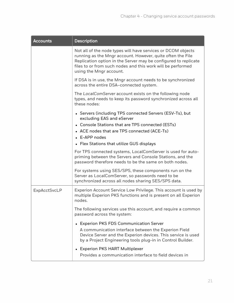
Accounts Description
Not all of the node types will have services or DCOM objects running as the Mngr account. However, quite often the File Replication option in the Server may be configured to replicate files to or from such nodes and this work will be performed using the Mngr account.
If DSA is in use, the Mngr account needs to be synchronized across the entire DSA–connected system.
The LocalComServer account exists on the following node types, and needs to keep its password synchronized across all these nodes:
l Servers (including TPS connected Servers (ESV-Ts), but excluding EAS and eServer
l Console Stations that are TPS connected (ESTs) l ACE nodes that are TPS connected (ACE-Ts) l E-APP nodes l Flex Stations that utilize GUS displays
For TPS connected systems, LocalComServer is used for auto-priming between the Servers and Console Stations, and the password therefore needs to be the same on both nodes.
For systems using SES/SPS, these components run on the Server as LocalComServer, so passwords need to be synchronized across all nodes sharing SES/SPS data.
ExpAcctSvcLP Experion Account Service Low Privilege. This account is used by multiple Experion PKS functions and is present on all Experion nodes.
The following services use this account, and require a common password across the system:
l Experion PKS FDS Communication ServerA communication interface between the Experion Field Device Server and the Experion devices. This service is used by a Project Engineering tools plug-in in Control Builder.
l Experion PKS HART MultiplexerProvides a communication interface to field devices in
Chapter 4 - Changing service account passwords

Accounts Description
Experion PKS. This service is used by a Project Engineering tools plug-in in Control Builder.
l Experion PKS Field Device ServerProvides device-related online and offline services. This service is used by a Project Engineering tools plug-in in Control Builder.
l Experion PKS Search Cache Builder ServerResponsible for retrieving the Display file details and the search settings stored in the Experion Search Cache database which is present in the Experion Server node.
Changing passwords for single-machine scope accounts
Despite the account’s scope only being to one node, the larger use of that node needs to be considered. For example, if you are changing the LocalComServer account on a Server node, you also need to consider that restarting this node to ensure all Services and DCOM objects pick up the change in the LocalComServer account will cause a disruption to other nodes depending on this node via multi–machine or system wide accounts.
If the account whose password is being changed is on such a node, the password change should be performed at a time when that node is not critical to operation. A policy around choosing an appropriate time to reboot a node should already be in place for dealing with Microsoft Security Updates, so that policy could be reused to determine the appropriate time to restart a node. The password change should then be scheduled as close as possible prior to this restart.
To change the Windows account password
1. Navigate to the directory containing the pwdutil.exe file. 2. Right-click on the pwdutil.exe and choose Run as Administrator. 3. Click OK to accept the UAC prompt. 4. Click the appropriate account. 5. Type the new password and then click OK.
22
Chapter 4 - Changing service account passwords
23
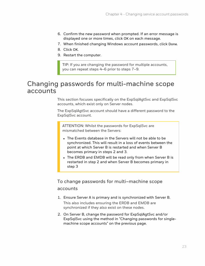
6. Confirm the new password when prompted. If an error message is displayed one or more times, click OK on each message.
7. When finished changing Windows account passwords, click Done. 8. Click OK. 9. Restart the computer.
TIP: If you are changing the password for multiple accounts, you can repeat steps 4–6 prior to steps 7–9.
Changing passwords for multi-machine scope accounts
This section focuses specifically on the ExpSqlAgtSvc and ExpSqlSvc accounts, which exist only on Server nodes.
The ExpSqlAgtSvc account should have a different password to the ExpSqlSvc account.
ATTENTION: Whilst the passwords for ExpSqlSvc are mismatched between the Servers:
l The Events database in the Servers will not be able to be synchronized. This will result in a loss of events between the point at which Server B is restarted and when Server B becomes primary in steps 2 and 3.
l The ERDB and EMDB will be read only from when Server B is restarted in step 2 and when Server B becomes primary in step 3
To change passwords for multi–machine scope accounts
1. Ensure Server A is primary and is synchronized with Server B. This also includes ensuring the ERDB and EMDB are synchronized if they also exist on these nodes.
2. On Server B, change the password for ExpSqlAgtSvc and/or ExpSqlSvc using the method in "Changing passwords for single-machine scope accounts" on the previous page.
Chapter 4 - Changing service account passwords
3. Once Server B has restarted, synchronize it with Server A, and then failover to Server B.
4. On Server A, change the password for ExpSqlAgtSvc and/or ExpSqlSvc using the method in "Changing passwords for single-machine scope accounts" on page 22
5. Once Server A has restarted, synchronize it with Server B. 6. (Optional) Failover to Server A and synchronize Servers. 7. If you have a system with Backup Control Center (BCC), repeat
steps 1 to 6 for each server location.
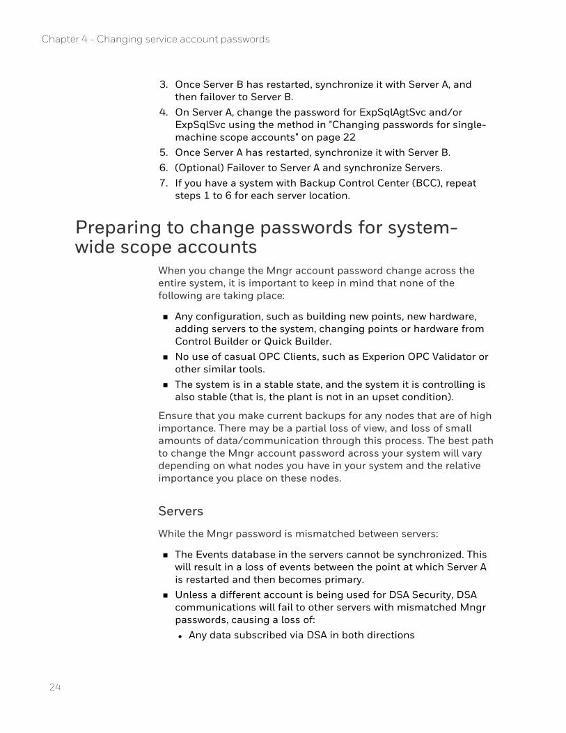
Preparing to change passwords for system-wide scope accounts
When you change the Mngr account password change across the entire system, it is important to keep in mind that none of the following are taking place:
n Any configuration, such as building new points, new hardware, adding servers to the system, changing points or hardware from Control Builder or Quick Builder.
n No use of casual OPC Clients, such as Experion OPC Validator or other similar tools.
n The system is in a stable state, and the system it is controlling is also stable (that is, the plant is not in an upset condition).
Ensure that you make current backups for any nodes that are of high importance. There may be a partial loss of view, and loss of small amounts of data/communication through this process. The best path to change the Mngr account password across your system will vary depending on what nodes you have in your system and the relative importance you place on these nodes.
Servers
While the Mngr password is mismatched between servers:
n The Events database in the servers cannot be synchronized. This will result in a loss of events between the point at which Server A is restarted and then becomes primary.
n Unless a different account is being used for DSA Security, DSA communications will fail to other servers with mismatched Mngr passwords, causing a loss of: l Any data subscribed via DSA in both directions
24
Chapter 4 - Changing service account passwords

25
l Any notifications subscribed via DSA in both directions n ACE nodes with mismatched Mngr passwords will continue to be
able to communicate with the server, with the exception of the OPC Gateway from the ACE to the server's OPC server.
n Console Stations with mismatched Mngr password will not be able to connect to the Server.
n OPC clients or servers with mismatched Mngr passwords will not be able to connect to the server's OPC server, OPC scan task, OPC Advanced Client, or OPC Integrator.
n PHD Severs with mismatched Mngr passwords will not be able to connect to the Server
n The server will be unable to connect to ODBC Database connections on behalf of ODBC Data Exchange.
n File Replication will fail to any node with a mismatched Mngr password.
n The server will be unable to connect to printers using the Mngr account when the password is mismatched.
Console Stations
Whilst the Mngr password is mismatched between a Console Station and its server, the Console Station will run in server disconnected mode.
Flex Stations
There is no impact on Flex Stations if its Mngr password is mismatched with the current primary server, unless File Replication is configured to replicate files between the server and the Flex Station. File Replication will fail when the Mngr password is mismatched between the Flex and the current primary server.
Engineering Stations
Much like Flex Stations, an Engineering Station will only be impacted by a mismatched Mngr password if File Replication is setup to the Engineering Station, and the Engineering Station's Mngr password does not match the password of the current primary server.
In addition, if the Engineering Station is using an OPC Client to connect to the server, the server will be calling back to the client using the Mngr account and this will fail.
Chapter 4 - Changing service account passwords
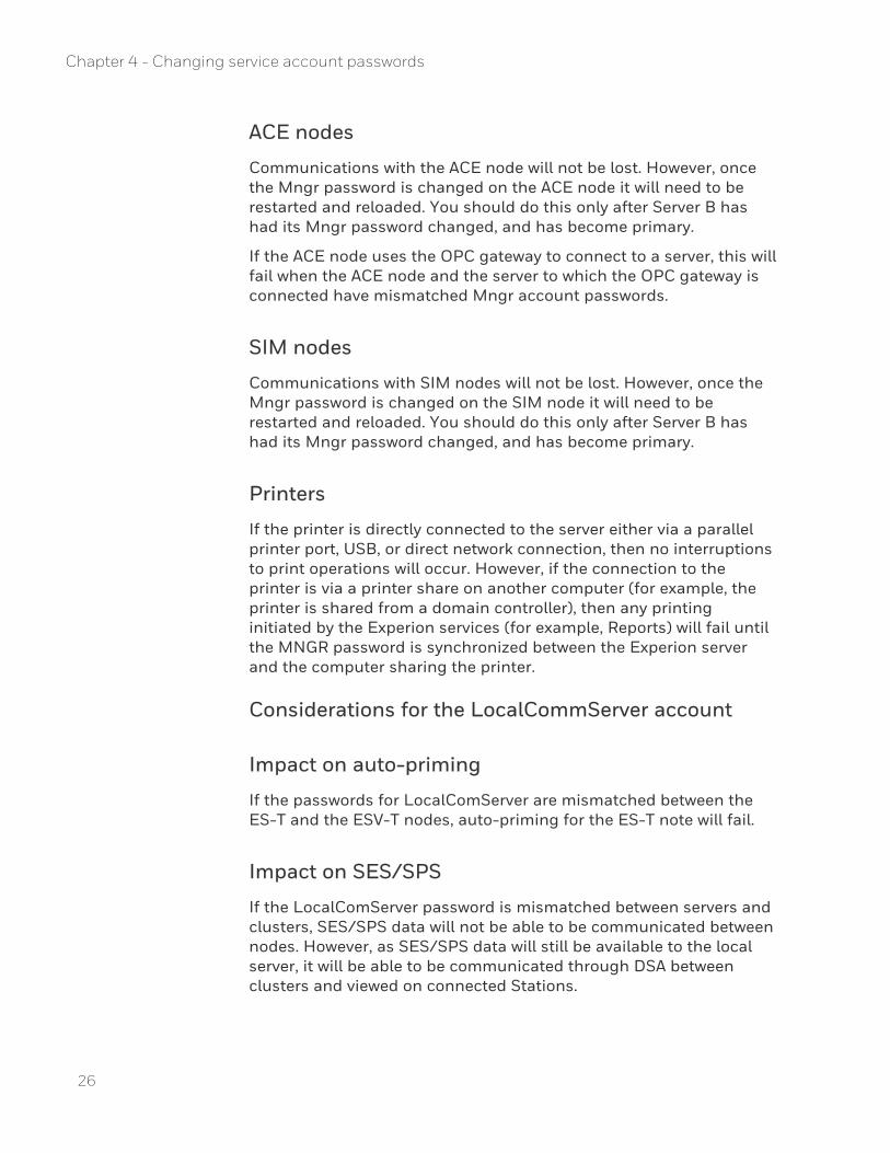
ACE nodes
Communications with the ACE node will not be lost. However, once the Mngr password is changed on the ACE node it will need to be restarted and reloaded. You should do this only after Server B has had its Mngr password changed, and has become primary.
If the ACE node uses the OPC gateway to connect to a server, this will fail when the ACE node and the server to which the OPC gateway is connected have mismatched Mngr account passwords.
SIM nodes
Communications with SIM nodes will not be lost. However, once the Mngr password is changed on the SIM node it will need to be restarted and reloaded. You should do this only after Server B has had its Mngr password changed, and has become primary.
Printers
If the printer is directly connected to the server either via a parallel printer port, USB, or direct network connection, then no interruptions to print operations will occur. However, if the connection to the printer is via a printer share on another computer (for example, the printer is shared from a domain controller), then any printing initiated by the Experion services (for example, Reports) will fail until the MNGR password is synchronized between the Experion server and the computer sharing the printer.
Considerations for the LocalCommServer account
Impact on auto-priming
If the passwords for LocalComServer are mismatched between the ES-T and the ESV-T nodes, auto-priming for the ES-T note will fail.
Impact on SES/SPS
If the LocalComServer password is mismatched between servers and clusters, SES/SPS data will not be able to be communicated between nodes. However, as SES/SPS data will still be available to the local server, it will be able to be communicated through DSA between clusters and viewed on connected Stations.
26
Chapter 4 - Changing service account passwords
27
Strategy to change the LocalComServer password
It is recommended that you change the LocalComServer password whenever you change the Mngr password. You can use the same procedure as for changing the Mngr password, simply substituting LocalComServer for Mngr.
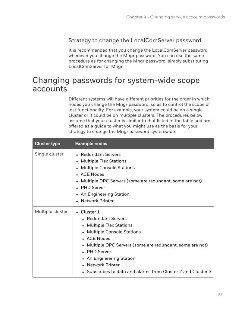
Changing passwords for system-wide scope accounts
Different systems will have different priorities for the order in which nodes you change the Mngr password, so as to control the scope of lost functionality. For example, your system could be on a single cluster or it could be on multiple clusters. The procedures below assume that your cluster is similar to that listed in the table and are offered as a guide to what you might use as the basis for your strategy to change the Mngr password systemwide.
Cluster type Example nodes
Single cluster l Redundant Servers l Multiple Flex Stations l Multiple Console Stations l ACE Nodes l Multiple OPC Servers (some are redundant, some are not) l PHD Server l An Engineering Station l Network Printer
Multiple cluster l Cluster 1 l Redundant Servers l Multiple Flex Stations l Multiple Console Stations l ACE Nodes l Multiple OPC Servers (some are redundant, some are not) l PHD Server l An Engineering Station l Network Printer l Subscribes to data and alarms from Cluster 2 and Cluster 3
Chapter 4 - Changing service account passwords
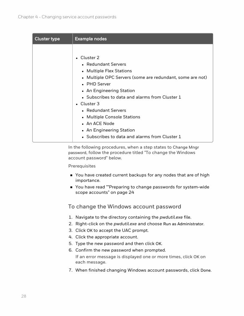
Cluster type Example nodes
l Cluster 2 l Redundant Servers l Multiple Flex Stations l Multiple OPC Servers (some are redundant, some are not) l PHD Server l An Engineering Station l Subscribes to data and alarms from Cluster 1
l Cluster 3 l Redundant Servers l Multiple Console Stations l An ACE Node l An Engineering Station l Subscribes to data and alarms from Cluster 1
In the following procedures, when a step states to Change Mngr password, follow the procedure titled "To change the Windows account password" below.
Prerequisites
n You have created current backups for any nodes that are of high importance.
n You have read ""Preparing to change passwords for system-wide scope accounts" on page 24
To change the Windows account password
1. Navigate to the directory containing the pwdutil.exe file. 2. Right-click on the pwdutil.exe and choose Run as Administrator. 3. Click OK to accept the UAC prompt. 4. Click the appropriate account. 5. Type the new password and then click OK. 6. Confirm the new password when prompted.
If an error message is displayed one or more times, click OK on each message.
7. When finished changing Windows account passwords, click Done.
28
Chapter 4 - Changing service account passwords
29
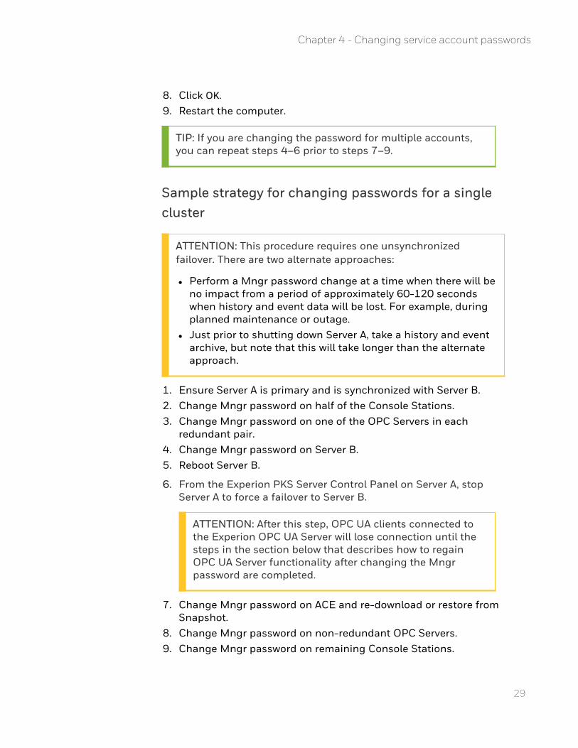
8. Click OK. 9. Restart the computer.
TIP: If you are changing the password for multiple accounts, you can repeat steps 4–6 prior to steps 7–9.
Sample strategy for changing passwords for a single cluster
ATTENTION: This procedure requires one unsynchronized failover. There are two alternate approaches:
l Perform a Mngr password change at a time when there will be no impact from a period of approximately 60-120 seconds when history and event data will be lost. For example, during planned maintenance or outage.
l Just prior to shutting down Server A, take a history and event archive, but note that this will take longer than the alternate approach.
1. Ensure Server A is primary and is synchronized with Server B. 2. Change Mngr password on half of the Console Stations. 3. Change Mngr password on one of the OPC Servers in each
redundant pair. 4. Change Mngr password on Server B. 5. Reboot Server B.
6. From the Experion PKS Server Control Panel on Server A, stop Server A to force a failover to Server B.
ATTENTION: After this step, OPC UA clients connected to the Experion OPC UA Server will lose connection until the steps in the section below that describes how to regain OPC UA Server functionality after changing the Mngr password are completed.
7. Change Mngr password on ACE and re-download or restore from Snapshot.
8. Change Mngr password on non-redundant OPC Servers. 9. Change Mngr password on remaining Console Stations.
Chapter 4 - Changing service account passwords
10. Change Mngr password on the remaining OPC Servers in each redundant pair.
11. Change Mngr password on Flex Stations. 12. Change Mngr password on Engineering Station. 13. Adjust Network Printer or Print Server to allow Mngr access with
new password. 14. Change Mngr password on Server A. 15. Reboot Server A. 16. Synchronize Server B and Server A. 17. (Optional) Failover to Server A. 18. Change Mngr password on PHD Server. 19. Follow the procedure below to regain OPC UA Server functionality
after changing the Mngr password.
Possible variations on this could include:
n As an additional step prior to step 4, change Mngr password on half of the Flex Stations.Typically, this would only be in cases where there are critical files distributed to the Flex Station via File Replication that would need to be updated between steps 4 and 11.
n As an additional step prior to step 4, change Mngr password on some/all of the non-Redundant OPC servers.This ensures that OPC data is available as soon as Server B becomes primary.
n Steps 4 to 6 should always be done consecutively. n Steps 7 to 13 can be reordered depending on your needs. n Step 13 may be deferred till after all other steps are complete n Steps 14 to 16 should always be done consecutively.
To regain OPC UA Server functionality after changing the Mngr password
1. On Server A and on Server B, navigate to <data folder>\Honeywell\Experion PKS\Server\data.Where <data folder> is the location where Experion data is stored. For default installations, <data folder> is C:\ProgramData.
30
Chapter 4 - Changing service account passwords
31
NOTE: The C:\ProgramData and C:\Program Files (x86) folders are system folders, which means that they are only visible if you select the Show hidden files, folders, and drives option button in the Folder Options dialog box. To change this setting in Windows Explorer, click Organize > Folder and search options, and then select the View tab.
2. Delete the folder Certstore.
3. Open a command prompt window with Administrator privilege and navigate to <install folder>\Honeywell\Experion PKS\Server\Run.Where <install folder> is the location where Experion is installed. For default installations this is C:\Program Files (x86).
4. Run hscconfig /createcertstoredir.
5. Reissue the OPC UA Server certificate. For more information, see "Setting up secure communication for a third-party OPC UA client" in the Supplementary Installation Tasks Guide.
Sample strategy for changing passwords for multiple clusters
1. For each cluster, complete steps 1 to 5 in the procedure above for the single cluster.Skip the steps for those node types that are not included in that cluster.
2. Failover to Server B in all clusters simultaneously. 3. For each cluster, complete steps 7 to 15 in the procedure above
for the single cluster.Skip the steps for those node types that are not included in that cluster.
4. (Optional) Failover to Server A in all clusters. 5. Change MNGR password on PHD Servers.
Chapter 4 - Changing service account passwords

32
Chapter 4 - Changing service account passwords
CHAPTER
5 CHANGING DSA ADVANCED SECURITY ACCOUNTS PASSWORDS
Overview
This section guides you in changing the password for a DSA Advanced Security account. The password must be the same on the publisher and subscriber nodes in DSA-connected systems.
To change the DSA Advanced Security account password
1. From the publisher node in the DSA system, enter Ctrl + Alt + Del.
2. Choose Change a password to display the new password screen. 3. Enter the DSA account Username, Old password, and New password,
then press Enter. 4. In Station, use the menu bar to navigate to Configure, System
Hardware, Distributed Servers. The Distributed Servers display appears.
5. Select the DSA connection you want to change the password for to display the Distributed Server Detail display.
6. From the Configuration tab, under Advanced Security, type the new password for the DSA Advanced Security account, and click Save. A confirmation message is displayed in the Message Zone, stating that the changed has been successful.
7. Repeat steps 1 to 6 for each DSA Advanced Security account on the subscriber.
33

34
Chapter 5 - Changing DSA Advanced Security accounts passwords
CHAPTER
6 WINDOWS MNGR ACCOUNT AND EXPERION SERVICES AND PROCESSES
The Windows mngr account is created with User privileges during the Experion installation process. The Experion services and some other Experion processes run under this account.
The mngr password and OPC Classic clientsWhen the Experion OPC Interface connects to a third-party OPC server over the network, it uses the Windows mngr account and password on the Experion server to connect to the computer running the OPC server. If this login fails, the OPC connection is refused.
To ensure that security does not become an issue for OPC Connections, ensure that a guest account exists on the third-party OPC server computer with the same name and password as the Windows mngr account on the Experion server computer.
The mngr password and ODBC Data Exchange security settings When the Experion ODBC Data Exchange report connects to an ODBC compliant database over the network, it uses the Windows mngr account and password on the Experion server to connect to the computer running the database. If this login fails, the ODBC connection is refused.
To ensure that security does not become an issue for ODBC connections, ensure that the guest account on the computer exists with the same name and password as the Windows mngr account on the Experion server computer.
The mngr password and print settings for alarms, events, and reports When the Experion server attempts to print Experion alarms, events, or reports to a printer that is connected to a remote computer, the server uses the Windows mngr account and password to make a connection to the remote computer. If the login fails, the print job is rejected.
The account and password on the computer where the network printer resides must match the server account.
35

36
Chapter 6 - Windows mngr account and Experion services and processes
CHAPTER
7 RESTRICTING ACCESS TO OPERATING SYSTEMS AND NON-STATION SOFTWARE
To prevent an operator from accessing the operating system and software other than Station software, you can configure the computer as a ‘secure’ Station.
Setting up a secure Station involves securing the operating system and non-Station software as well as securing Station. The procedures can be used in conjunction with the High Security Policy. For more information on how to set up a secure Station, see "Securing the operating system" in the Windows Domain and Workgroup Planning Guide.
37

38
Chapter 7 - Restricting access to operating systems and non-Station software
CHAPTER
8 ABOUT THE SYSTEM TIME AND TIME ZONE
When you install the Windows operating system, the time is set to automatically adjust for daylight saving time. It is recommended that you retain this automatic adjustment.
The Experion server uses coordinated universal time (UTC) and its local time zone setting to determine how alarms and events are presented in summary displays and reports on connected Flex Stations. As a result:
n In summary displays, the newest alarms and events appear at the top. The time displayed is the local time as set on the Experion Server.
n In reports alarms and events are sorted by UTC. The time displayed is the local time as set on the Experion Server.
n Sequence of events reports lists events in their order they occurred.
NOTE: The time zone setting of the connected Flex Station does not affect the times of the alarms and events it displays; that time stamp is determined by the Experion server. The Windows-configured date and time formats in the connected Flex Station, however, are used as the time stamp format in Alarm and Event Summary displays.
For example, an Alarm Summary contains entries for alarms raised and 01.30 and 02.30. At 03.00 the time changes from daylight saving to standard time and the time on the server computer is reset to 02.00. Another alarm is raised at 02.15, after the time change from daylight saving. The alarm raised at 02.15 appears above the alarm raised at 02.30 daylight saving time. This ordering of alarms is correct since the alarm raised at 02.15 standard time is newer than the alarm raised at 02.30.
Process controller nodes and ACE nodes are continually updated with the correct (UTC) time from the server. The TIMEZONE and DAYLIGHTTIME parameters must be manually adjusted.
Any trends that are open during the time change to or from daylight saving time stop updating until the display is refreshed.
39

If you do not want the time automatically adjusted for daylight savings, contact your Honeywell Technical Assistance Center (TAC) for information on how to manually adjust for daylight saving time.
40
Chapter 8 - About the system time and time zone
CHAPTER
9 RESTORING SERVER B FROM A HARDWARE FAILURE OR CORRUPTED DATABASE
This procedure is used when you are replacing the hardware platform on server B or performing a clean installation on server B.
ATTENTION: If you used Experion Backup and Restore to back up server B, see the Experion Backup and Restore Guide for instructions.
To restore server B
1. Make sure that server A is running as primary. 2. Remove server B from the network (disconnect network cables). 3. Shutdown server B. 4. Replace server B. Do not connected network cables. 5. Restore server B, (install Windows operating system and Experion
server software, including any patches/ support media. The Windows operating system and Experion server software version and patch level must be the same as server A).
6. Create a hosts configuration file on server B that is similar to the hosts file on server A.
7. Open the Windows Administrative Tools. 8. Double-click Services. The Services management console window
appears. 9. Double-click on the Experion PKS ER Server service. The Experion
PKS ER Server Properties window appears. 10. Click the Dependencies tab, and note the names of the system
components that depend on this service. You will need to manually restart these services later, so it is important that you note these names now.
41

42
Chapter 9 - Restoring server B from a hardware failure or corrupted database
CHAPTER
10 CREATING NEW OPERATING SYSTEM VIRTUAL MACHINES AND TEMPLATES
Not all virtual machines can be installed using the Experion System Initialization media. For these nodes, you will need to create a virtual machine and then install the Windows operating system (which is installed using either the Microsoft media or the Experion System Initialization media), before installing the required application software for that node type. For example, the node types that need to follow this process are:
n Any application that is located at Level 2.5 or higher (DCS architecture).
n Any application at Level 2 (DCS architecture) where the required Windows operating system is supported by the Experion System Initialization media.
n Any application where the required Windows operating system is not supported by the Experion System Initialization media.
n Windows domain controllers located at Level 2 (DCS architecture).
In this section:
Preparing partition replacement virtual hard disks 44
Creating a virtual machine 47
Installing the Windows operating system using Microsoft media 50
Installing the Windows operating system using the Experion System Initialization media 51
Installing VMware Tools for a non-Experion Node 61
Configuring the Windows operating system 62
Completing the node installation 63
Creating operating system virtual machine templates 65
43
Preparing partition replacement virtual hard disks
If you configure the primary disk of your Experion VM with more than one partition you should consider replacing the additional logical partitions with virtual disks or Partition Replacement virtual disks.
Drive letters assigned to logical partitions created during the install of a virtual machine using ESIS and Utility disks start with F. Drive letters D and E are assigned to the ESIS and Utility Disks before the partition is created, so this leaves F as the first available drive letter. Replacing a logical disk partition with a "Partition Replacement virtual hard disk" allows you to control the assigned drive letters.
When creating the primary Virtual Hard disk for the Experion VM, remember to size it based on the total size identified in the HPS Virtualization Specification minus the total size of the partition replacement virtual disks.
For example: C: Primary Disk size = Total disk size - Partition disk size.
Currently, Experion has a 100 GB minimum size requirement for the C: primary drive. When dividing the recommended disk size into logical chunks, make sure the C: primary disk meets the current minimum required size.
As with the ESIS and Utility disks, create a master copy of the Partition replacement disk so it can be copied to the folder of the VM during the VM creation process.
Creating the partition virtual hard disk
1. From the vSphere Client, right-click on the ESIS/Utility creation virtual machine and click Rename. Record the current name and then change the name to D-Partition-HD or E-Partition-HD. This rename is required so that the new virtual hard disk .vmdk file is created with this name. You can use a name that more accurately represents the use of the partition if your system.
2. From the vSphere Client, right-click on the ESIS/Utility creation virtual machine and click Edit Settings.The Virtual Machine Properties dialog box appears.
3. Click the Hardware tab. 4. If more than one hard disk is listed, click Cancel. Browse to the
datastore and folder where the virtual machine is running and record the names of all the .vmdk files. This is to ensure that the
44
Chapter 10 - Creating new operating system virtual machines and templates

45
new hard disks that show as vmdk files are clearly identified after they are created.
5. Right-click on the ESIS/Utility creation virtual machine and click Edit Settings.
6. Click Add.The Add Hardware window appears.
7. Select Hard Disk and then click Next. 8. Select Create a new virtual disk and then click Next. 9. Change the disk size to the desired size for this partition in GB.
10. Clear the Allocate and commit space on demand (Thin Provisioning) check box.
11. Select the Ensure that Store with the virtual machine check box. 12. Click Next. 13. Select the Independent check box, then select Persistent. 14. Click Next. 15. Review the summary, then click Finish. 16. Click OK. 17. In the Home > Inventory > Datastores view, browse the datastore and
locate the folder where the ESIS/Utility creation virtual machine files are stored. You should see a new file called D or E-Partition-HD with the .vmdk extension.
18. From the vSphere Client, right-click on the ESIS/Utility creation virtual machine and choose Rename. Change the name back to the original name as seen in vCenter Server.
19. From the vSphere Client, connect to the console of the ESIS/Utility creation virtual machine and log on as a user with administrator privileges.
20. In the Windows Control Panel, click System, then Security , then Administrative Tools.
21. Double–click Computer Management
22. Select Disk Management.The Initialize Disk dialog box appears.
23. Ensure that the new disk and MBR are selected and then click OK.A new disk appears in the bottom center pane of the window and will have GB size specified earlier of unallocated space.
24. Right-click on the disk and click New Simple Volume.The New Simple Volume window appears.
Chapter 10 - Creating new operating system virtual machines and templates
25. Click Next. 26. Click Next. 27. Select Assign the following drive letter and assign an appropriate
drive letter to the new disk (the default value should be acceptable).
28. Click Next. 29. Ensure that the disk is to be formatted as NTFS with default
allocation unit size, change the volume label to D or E-Partition-HD, or give it a label.
30. Select the Perform a Quick Format check box, then click Next. 31. Review the settings and click Finish.
The new disk will now be visible in Windows Explorer as the specified Label Name.
Creating the master partition virtual hard diskThe master partition virtual hard disk can be copied to new Experion virtual machines to form the media requirements for an Experion node installation.
1. Remove the Partition virtual hard disk from the ESIS/Utility creation virtual machine:
a. Shutdown the ESIS/Utility creation virtual machine. To be able to remove the virtual hard disk, you need to shutdown the virtual machine first. If you don't shutdown the virtual machine, the operating system on the virtual machine is left in a state that may cause problems with EBR backups.
b. From the vSphere Client, right-click on the ESIS/Utility creation virtual machine and click Edit Settings.The Virtual Machine Properties window appears.
c. Click the Hardware tab. d. Select the Partition virtual hard disk (ensure that you select the
correct disk) and click Remove. e. Click Remove from virtual machine, then click OK.
2. In the datastore where you intend to store the master Partition file (the staging datastore), create a new folder in the root of the datastore and name it Partition-Master.This folder is where the Partition virtual hard disk .vmdk file will be copied to and kept as a master for future use. It is from this location that the .vmdk file will be copied from to new Experion virtual machines.
46
Chapter 10 - Creating new operating system virtual machines and templates
47
3. Move the Partition virtual hard disk to a new folder on the datastore.
a. Locate the partition .vmdk file created when the Partition virtual hard disk was created.
b. Cut and paste this file into the Partition-Master folder on the datastore.
c. Ensure that the .vmdk file does not appear in the ESIS/Utility creation virtual machine's datastore folder.
4. Create additional disk partitions as required. For more information, see the related topics.
Creating a virtual machineStart the New Virtual Machine Wizard and configure the required virtual machine.
n HPS Virtualization Specification.
n vSphere Virtual Machine Administration.
To create a virtual machine
1. Create a new virtual machine by following the instructions in vSphere Virtual Machine Administration. Use the following table to identify appropriate values to enter in the New Virtual Machine Wizard.
New Virtual Machine Wizard page
Description
Configuration Select Custom.
Name and Location
Type a unique and recognizable name for the virtual machine. Select a location, such as a folder, that is consistent with your chosen structure for organizing VMware inventory objects.
Datastore Select a datastore location, which can be local storage or shared storage (for Level 3 virtual machines on DCS architecture and SCADA architecture).
Chapter 10 - Creating new operating system virtual machines and templates
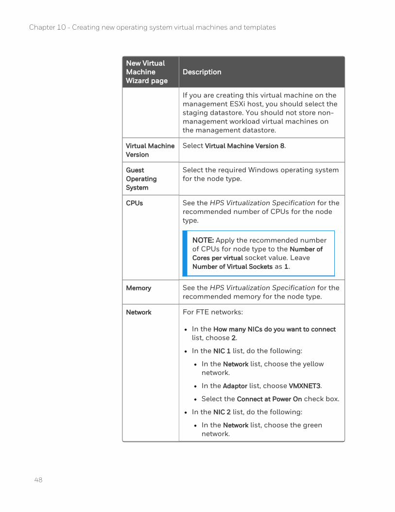
New Virtual Machine Wizard page
Description
If you are creating this virtual machine on the management ESXi host, you should select the staging datastore. You should not store non-management workload virtual machines on the management datastore.
Virtual Machine Version
Select Virtual Machine Version 8.
Guest Operating System
Select the required Windows operating system for the node type.
CPUs See the HPS Virtualization Specification for the recommended number of CPUs for the node type.
NOTE: Apply the recommended number of CPUs for node type to the Number of Cores per virtual socket value. Leave Number of Virtual Sockets as 1.
Memory See the HPS Virtualization Specification for the recommended memory for the node type.
Network For FTE networks:
l In the How many NICs do you want to connect list, choose 2.
l In the NIC 1 list, do the following:
l In the Network list, choose the yellow network.
l In the Adaptor list, choose VMXNET3.
l Select the Connect at Power On check box.
l In the NIC 2 list, do the following:
l In the Network list, choose the green network.
48
Chapter 10 - Creating new operating system virtual machines and templates
49
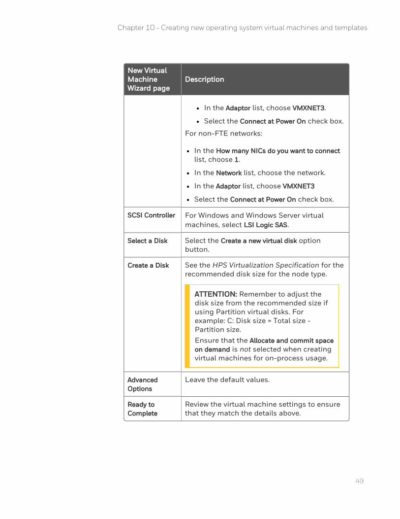
New Virtual Machine Wizard page
Description
l In the Adaptor list, choose VMXNET3.
l Select the Connect at Power On check box.
For non-FTE networks:
l In the How many NICs do you want to connect list, choose 1.
l In the Network list, choose the network.
l In the Adaptor list, choose VMXNET3
l Select the Connect at Power On check box.
SCSI Controller For Windows and Windows Server virtual machines, select LSI Logic SAS.
Select a Disk Select the Create a new virtual disk option button.
Create a Disk See the HPS Virtualization Specification for the recommended disk size for the node type.
ATTENTION: Remember to adjust the disk size from the recommended size if using Partition virtual disks. For example: C: Disk size = Total size - Partition size.Ensure that the Allocate and commit space on demand is not selected when creating virtual machines for on-process usage.
Advanced Options
Leave the default values.
Ready to Complete
Review the virtual machine settings to ensure that they match the details above.
Chapter 10 - Creating new operating system virtual machines and templates
Add partition virtual hard disks
1. Copy the Partition-HD .vmdk file or files from the Partition-Master folder to the new virtual machine's folder (this folder will have the same name as the virtual machine name, as shown in vCenter Server)
2. Edit this virtual machine's settings as follows: a. Add new hardware by selecting the following options:
l Hard disk
l Use an existing virtual disk
b. Browse this virtual machine datastore folder and select one Partition-HD .vmdk file in the desired drive letter order D then E, and so on.
c. Accept default value for Virtual Device Node
d. Make sure the Mode option of Independent is not checked, then finish adding the hard disk.
e. Repeat this process for each Partition virtual hard disk.
Installing the Windows operating system using Microsoft media
You can install the Windows operating system using the Microsoft media or using the Experion System Initialization media. You should use the Microsoft media for nodes connecting to the Level 3 network in a DCS architecture.
That is, you should install the Windows operating system using Microsoft media for the following nodes:
n Any application that is located at Level 2.5 or higher (DCS architecture).
n Any application where the required Windows operating system is not supported by the Experion System Initialization media.
n Windows operating system installation media or an ISO image of the Windows operating system installation media that has been uploaded to the virtual infrastructure.
n Guest Operating System Installation Guide on the VMware web site.
50
Chapter 10 - Creating new operating system virtual machines and templates
51
To install the Windows operating system using the Microsoft media
1. In the “General Installation Instructions for All VMware Products” topic in the “Installing Guest Operating Systems” chapter of the Guest Operating System Installation Guide, review the typical installation instructions.
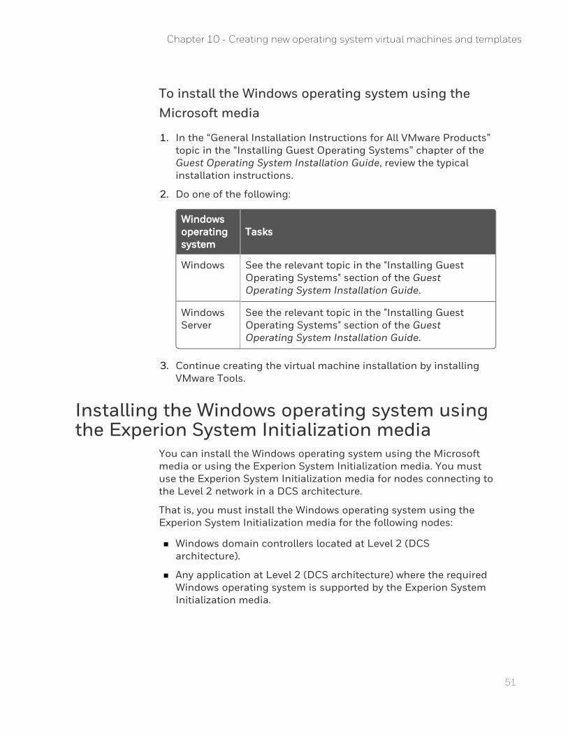
2. Do one of the following:
Windows operating system
Tasks
Windows See the relevant topic in the "Installing Guest Operating Systems" section of the Guest Operating System Installation Guide.
Windows Server
See the relevant topic in the "Installing Guest Operating Systems" section of the Guest Operating System Installation Guide.
3. Continue creating the virtual machine installation by installing VMware Tools.
Installing the Windows operating system using the Experion System Initialization media
You can install the Windows operating system using the Microsoft media or using the Experion System Initialization media. You must use the Experion System Initialization media for nodes connecting to the Level 2 network in a DCS architecture.
That is, you must install the Windows operating system using the Experion System Initialization media for the following nodes:
n Windows domain controllers located at Level 2 (DCS architecture).
n Any application at Level 2 (DCS architecture) where the required Windows operating system is supported by the Experion System Initialization media.
Chapter 10 - Creating new operating system virtual machines and templates
Identifying the operating system and template requirementsBefore commencing an operating system installation, it is important to identify a number of key configuration items. These items help prepare the Utility virtual hard disk and highlight any important information that may be needed.
Templates
n Define a template name for each operating system. This is important so that a template can be clearly identified. A simple name like TEMP-Win7 could be used.
n IP address. Each template should have a unique IP address. This IP address should be outside of the normal process control network range and will ensure that a template cannot become a duplicate of an Experion node.
Operating system installation
n A unique name of less than 15 characters.
n A unique Microsoft product key.
n A unique IP address.
Creating the Utility virtual hard diskIf you have an existing Utility virtual hard disk, you can skip this task.
To create the Utility virtual hard disk
1. From the vSphere Client, right-click on the ESIS/Utility creation virtual machine and choose Rename.Record the current name and then change the name to Utility. This rename is required so that the new virtual hard disk .vmdk file is created with this name. You can use a name that includes the Experion release in the name (for example, Utility-EPKSR500-2) if your system could include future releases of Experion that require another Utility virtual hard disk.
2. From the vSphere Client, right-click on the ESIS/Utility creation virtual machine and choose Edit Settings.The Virtual Machine Properties window appears.
52
Chapter 10 - Creating new operating system virtual machines and templates

53
3. Click the Hardware tab. 4. If more than one Hard disk is listed, click Cancel. Browse to the
datastore and folder where the virtual machine is running and record the names of all the .vmdk files. This is to ensure that the new hard disks that show as vmdk files are clearly identified after they are created. Right-click on the ESIS/Utility creation virtual machine and choose Edit Settings.
5. Click Add.The Add Hardware wizard appears.
6. Select Hard Disk and then click Next. 7. Select Create a new virtual disk and then click Next. 8. Change Disk Size to 5 GB. 9. Select the Select Thin Provisioning udder disk provisioning option
check box. 10. Ensure that Store with the virtual machine is selected. 11. Click Next. 12. In the Virtual Device Node list, use the default value. 13. Select the Independent check box and then select Persistent. 14. Click Next. 15. Review the summary and then click Finish. 16. Click OK to close the Virtual Machine Properties window. 17. In the Home > Inventory > Datastores views, browse the datastore
(right-click on the datastore and choose Browse) and locate the folder where the ESIS/Utility creation virtual machine files are stored. You should see a new file with the .vmdk extension. The file should have the ESIS/Utility creation virtual machine name and possibly a numeric suffix. The file should indicate 5,242,880KB in provisioned size. Record the current name of this file as it will be used later.
18. From the vSphere Client, right-click on the ESIS/Utility creation virtual machine and choose Rename.Change the name back to the original name as seen in vCenter Server.
19. From the vSphere Client, connect to the console of the ESIS/Utility creation virtual machine, or if you are already connected to the ESIS/Utility creation virtual machine, log on as a user with administrator privileges.
20. In the Windows Control Panel, click System and Security, then Administrative Tools. Double click Computer Management.
Chapter 10 - Creating new operating system virtual machines and templates

21. In the left tree, select Disk Management.The Initialize Disk dialog box appears.
22. Ensure that the new disk and MBR are selected and then click OK.A new disk appears in the bottom center pane of the window and will have 5.00GB of unallocated space.
23. Right-click on the on the disk and choose New Simple Volume.The New simple volume wizard appears.
24. Click Next. 25. Click Next. 26. Select Assign the following drive letter and assign an appropriate
drive letter to the new disk (the default should be acceptable). 27. Click Next. 28. Ensure that the disk is to be formatted as NTFS with default
allocation unit size, change the volume label to Utility, select the Perform a Quick Format check box, and then click Next.
29. Review the settings and click Finish.The new disk will now be visible in Computer as Utility.
Creating the Experion System Initialization media configuration files for operating system only installationsExperion System Initialization media configuration files are required to install the Experion node operating system for templates. These configuration files will be created in a unique folder on the Utility virtual hard disk so that each new virtual machine can access all the required files to complete an unattended installation and install third-party software.
n Experion System Initialization media (R100.3 or later).
To create the Experion System Initialization media configuration files for operating system only installations
1. On the management host (the ESXi host containing the vSphere Server virtual machine), create a folder named ISO_Media on the datastore.
2. Convert the contents of the Experion System Initialization media to an ISO file.
3. Copy the ISO file to the ISO_Media folder that you created on the ESXi host datastore.
54
Chapter 10 - Creating new operating system virtual machines and templates
55
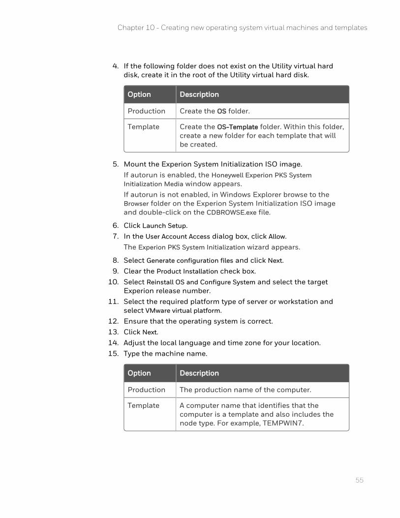
4. If the following folder does not exist on the Utility virtual hard disk, create it in the root of the Utility virtual hard disk.
Option Description
Production Create the OS folder.
Template Create the OS-Template folder. Within this folder, create a new folder for each template that will be created.
5. Mount the Experion System Initialization ISO image.If autorun is enabled, the Honeywell Experion PKS System Initialization Media window appears.If autorun is not enabled, in Windows Explorer browse to the Browser folder on the Experion System Initialization ISO image and double-click on the CDBROWSE.exe file.
6. Click Launch Setup. 7. In the User Account Access dialog box, click Allow.
The Experion PKS System Initialization wizard appears.
8. Select Generate configuration files and click Next. 9. Clear the Product Installation check box.
10. Select Reinstall OS and Configure System and select the target Experion release number.
11. Select the required platform type of server or workstation and select VMware virtual platform.
12. Ensure that the operating system is correct. 13. Click Next. 14. Adjust the local language and time zone for your location. 15. Type the machine name.
Option Description
Production The production name of the computer.
Template A computer name that identifies that the computer is a template and also includes the node type. For example, TEMPWIN7.
Chapter 10 - Creating new operating system virtual machines and templates
16. Clear the Microsoft Embedded COA check box. The Windows operating system product key will not be applied and activated until the running node is deployed from the template.
17. Leave the User as Experion Admin and type a strong password. 18. Click Next. 19. Select the required network type. 20. Assign the IP address reserved for this virtual machine to the FTE
Yellow Ethernet adapter (for level 2 FTE networks) or to the single Ethernet adapter (for level 3 networks). Leave the FTE Green Ethernet adapter with default values.
21. For level 2 FTE networks, adjust any other FTE configurations.The FTE Multicast address, and UDP source and destination ports must match the settings of an existing system for correct integration.
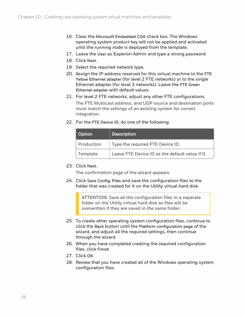
22. For the FTE Device ID, do one of the following:
Option Description
Production Type the required FTE Device ID.
Template Leave FTE Device ID as the default value if 0.
23. Click Next.The confirmation page of the wizard appears.
24. Click Save Config. Files and save the configuration files to the folder that was created for it on the Utility virtual hard disk.
ATTENTION: Save all the configuration files in a separate folder on the Utility virtual hard disk as files will be overwritten if they are saved in the same folder.
25. To create other operating system configuration files, continue to click the Back button until the Platform configuration page of the wizard, and adjust all the required settings, then continue through the wizard.
26. When you have completed creating the required configuration files, click Finish.
27. Click OK. 28. Review that you have created all of the Windows operating system
configuration files.
56
Chapter 10 - Creating new operating system virtual machines and templates
57
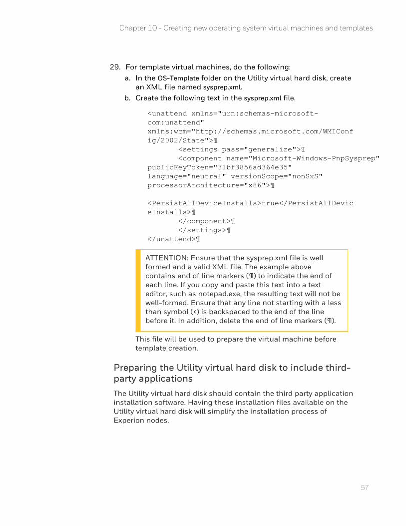
29. For template virtual machines, do the following: a. In the OS-Template folder on the Utility virtual hard disk, create
an XML file named sysprep.xml. b. Create the following text in the sysprep.xml file.
<unattend xmlns="urn:schemas-microsoft-com:unattend" xmlns:wcm="http://schemas.microsoft.com/WMIConfig/2002/State">¶ <settings pass="generalize">¶ <component name="Microsoft-Windows-PnpSysprep" publicKeyToken="31bf3856ad364e35" language="neutral" versionScope="nonSxS" processorArchitecture="x86">¶ <PersistAllDeviceInstalls>true</PersistAllDeviceInstalls>¶ </component>¶ </settings>¶ </unattend>
ATTENTION: Ensure that the sysprep.xml file is well formed and a valid XML file. The example above contains end of line markers (¶) to indicate the end of each line. If you copy and paste this text into a text editor, such as notepad.exe, the resulting text will not be well-formed. Ensure that any line not starting with a less than symbol (<) is backspaced to the end of the line before it. In addition, delete the end of line markers (¶).
This file will be used to prepare the virtual machine before template creation.
Preparing the Utility virtual hard disk to include third-party applicationsThe Utility virtual hard disk should contain the third party application installation software. Having these installation files available on the Utility virtual hard disk will simplify the installation process of Experion nodes.
Chapter 10 - Creating new operating system virtual machines and templates
To prepare the Utility virtual hard disk to include third-party applications
1. At the root of the Utility virtual hard disk, create the APPS folder. 2. Copy any third-party application installer files, such as anti-virus
and Microsoft Office to the APPS folder. You may also consider downloading the latest Honeywell supplied Microsoft operating system and Office patches and include these.
3. If any of the Experion nodes are to be connected to an IKB keyboard, copy the Wyse TCX Software Suite installation files to the APPS folder.For more information on how to download the Wyse TCX Software Suite, see the related topics.
Creating the master Utility virtual hard diskYou need to create a master Utility virtual hard disk so that a known Utility repository is available in the virtual infrastructure, which can then be copied to new Experion virtual machines to form the media requirements for an Experion node installation.
To create the master Utility virtual hard disk
1. Remove the Utility virtual hard disk from the ESIS/Utility creation virtual machine:
a. Shutdown the ESIS/Utility creation virtual machine.To be able to remove the virtual hard disk, you need to shutdown the virtual machine first. If you don’t shutdown the virtual machine, the operating system on the virtual machine is left in a state that may cause problems with EBR backups.
b. From the vSphere Client, right-click on the ESIS/Utility creation virtual machine and choose Edit Settings.The Virtual Machine Properties window appears.
c. Click the Hardware tab. d. Select the Utility virtual hard disk (ensure that you select the
correct 5GB disk) and click Remove. e. Click the Remove from virtual machine option button and then
click OK. 2. In the datastore where you intend to store the master Utility file
(the staging datastore), create a new folder in the root of the datastore and name it Utility-Master.
58
Chapter 10 - Creating new operating system virtual machines and templates
59
This folder is where the Utility virtual hard disk .vmdk file will be copied to and kept as a master for future use. It is from this location that the .vmdk file will be copied from to new Experion virtual machines.
3. Move the Utility virtual hard disk to a new datastore folder by following these steps:
a. Locate the 5GB vmdk file that was created when the Utility virtual hard disk was created.
b. Cut and paste this file into the Utility-Master folder on the datastore.
c. Ensure that the .vmdk file does not appear in the ESIS/Utility creation virtual machine’s datastore folder where you copied the .vmdk file from.
Starting the Experion System Initialization media installation
Prerequisites
n You have created the master Utility virtual hard disk.
n You have created a virtual machine
To attach the Utility virtual hard disk to the virtual machine
1. Mount the Experion System Initialization media ISO image and ensure that the Connect at power on check box is selected.If you are performing this installation on a production ESXi host, you will need to first copy the ISO file to a local datastore on that ESXi host.
2. Copy the master Utility vmdk file from the Utility-Master folder to the new virtual machine’s folder (this folder will have the same name as the virtual machine, as shown in vSphere Client).
3. Add a new virtual hard disk to the virtual machine: a. Select to use an existing virtual disk. b. Browse the virtual machine datastore folder and select the
Utility vmdk file that was copied into the virtual machine's folder.
4. Select the advanced options of Independent and Nonpersisient. 5. Click OK.
Chapter 10 - Creating new operating system virtual machines and templates
To restart the virtual machine from the Experion System Initialization media to start the unattended installation
1. Power on the virtual machine. It will start from the Experion System Initialization media ISO file mounted as a DVD. A dialog box appears requesting the Experion System Initialization media configuration files to continue.
2. Browse to the required node folder in either the OS-Templates folder or the OS folder in the Utility virtual hard drive and select the InitMediaOptions.xml file for the node or template that you want to install.
3. Click Next.
ATTENTION: Drive letters assigned to additional logical partitions on the primary disk will start from drive letter E:. If drive letter assignment is important, Honeywell recommends replacing logical partitions with partition virtual disks that have been pre-configured and attached to this virtual machine prior to the Utility virtual hard disk.
4. Select the DVD option then click Next. 5. Read and accept the license agreement and then click Install.
ATTENTION: A dialog box appears indicating that multiple hard disks are detected. Ensure that the disk selected for formatting is the original virtual machine disk and not the Utility virtual hard disk drive. This will be easily determined by the size of the disk.
6. Click Yes to continue.The operating system will now be installed in an unattended mode and user interaction is only required when the Windows operating system installation media is requested to complete the installation.
7. When prompted, insert the Windows operating system media. 8. After the virtual machine restarts, log in to the Windows operating
system, and then insert the Experion System Initialization media to perform the post installation tasks.
9. When the installation is complete, click OK.The virtual machine restarts.
60
Chapter 10 - Creating new operating system virtual machines and templates
61
Installing VMware Tools for a non-Experion Node
VMware Tools enhance the performance of the virtual machine’s guest operating system and improves the management of the virtual machine.
Prerequisite
Installing and Configuring VMware Tools provides information for several VMware products to install, upgrade, and configure VMware Tools. When using this documentation, follow the instructions for "vSphere virtual machines".
To install VMware Tools
1. Install VMware Tools by following the instructions in the “Manually Install or Upgrade VMware Tools in a Windows Virtual Machine” of the Installing and Configuring VMware Tools.
2. In the vSphere Client, right-click on the virtual machine where you want to install VMware Tools and select GuestInstall/Upgrade VMware Tools.
3. Select the Interactive Tools Installation option button and then click OK.
4. Open the virtual machine’s console, and log into the Windows operating system.
5. If autorun is enabled, click OK to confirm the autorun to start. If autorun is not enabled, browse to the virtual CD/DVD drive and double-click the setup.exe file (or setup64.exe if running Windows 64-bit).The VMware Tools installation wizard appears.
6. Click Next. 7. Select the Typical option and then click Next. 8. Click Install. 9. Restart the virtual machine to complete the installation.
DO NOT configure the virtual machine to automatically upgrade VMware Tools when an updated version is available. This might affect the performance of the system. Hence, you need to manually upgrade to the newer version. For instructions, see the “Upgrade VMware Tools” topic in Installing and Configuring
Chapter 10 - Creating new operating system virtual machines and templates
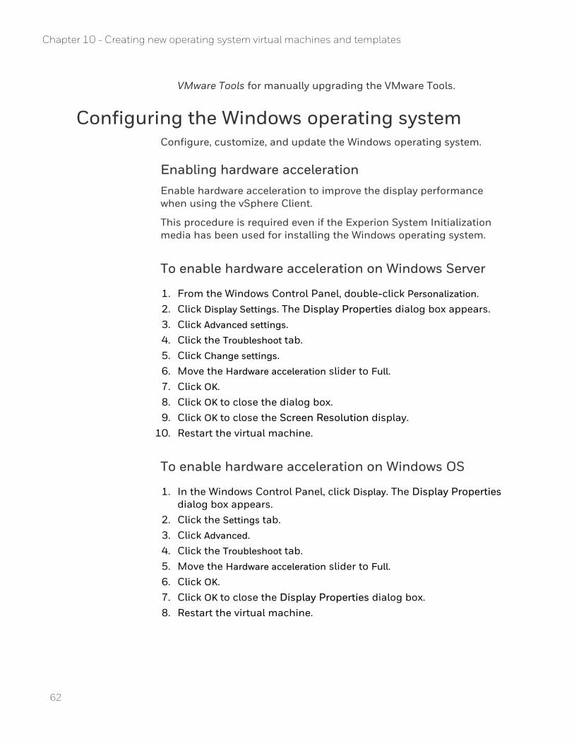
VMware Tools for manually upgrading the VMware Tools.
Configuring the Windows operating systemConfigure, customize, and update the Windows operating system.
Enabling hardware accelerationEnable hardware acceleration to improve the display performance when using the vSphere Client.
This procedure is required even if the Experion System Initialization media has been used for installing the Windows operating system.
To enable hardware acceleration on Windows Server
1. From the Windows Control Panel, double-click Personalization. 2. Click Display Settings. The Display Properties dialog box appears. 3. Click Advanced settings. 4. Click the Troubleshoot tab. 5. Click Change settings. 6. Move the Hardware acceleration slider to Full. 7. Click OK. 8. Click OK to close the dialog box. 9. Click OK to close the Screen Resolution display.
10. Restart the virtual machine.
To enable hardware acceleration on Windows OS
1. In the Windows Control Panel, click Display. The Display Properties dialog box appears.
2. Click the Settings tab. 3. Click Advanced. 4. Click the Troubleshoot tab. 5. Move the Hardware acceleration slider to Full. 6. Click OK. 7. Click OK to close the Display Properties dialog box. 8. Restart the virtual machine.
62
Chapter 10 - Creating new operating system virtual machines and templates
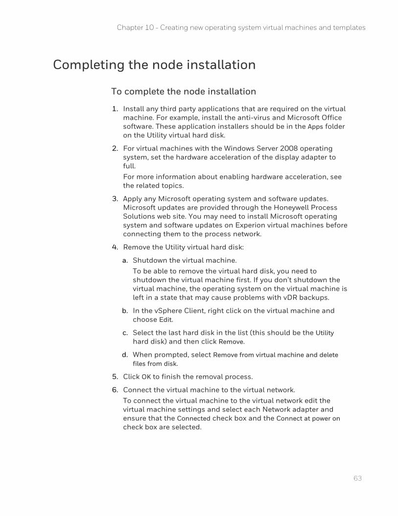
63
Completing the node installation
To complete the node installation
1. Install any third party applications that are required on the virtual machine. For example, install the anti-virus and Microsoft Office software. These application installers should be in the Apps folder on the Utility virtual hard disk.
2. For virtual machines with the Windows Server 2008 operating system, set the hardware acceleration of the display adapter to full.For more information about enabling hardware acceleration, see the related topics.
3. Apply any Microsoft operating system and software updates. Microsoft updates are provided through the Honeywell Process Solutions web site. You may need to install Microsoft operating system and software updates on Experion virtual machines before connecting them to the process network.
4. Remove the Utility virtual hard disk:
a. Shutdown the virtual machine.To be able to remove the virtual hard disk, you need to shutdown the virtual machine first. If you don’t shutdown the virtual machine, the operating system on the virtual machine is left in a state that may cause problems with vDR backups.
b. In the vSphere Client, right click on the virtual machine and choose Edit.
c. Select the last hard disk in the list (this should be the Utility hard disk) and then click Remove.
d. When prompted, select Remove from virtual machine and delete files from disk.
5. Click OK to finish the removal process.
6. Connect the virtual machine to the virtual network.To connect the virtual machine to the virtual network edit the virtual machine settings and select each Network adapter and ensure that the Connected check box and the Connect at power on check box are selected.
Chapter 10 - Creating new operating system virtual machines and templates
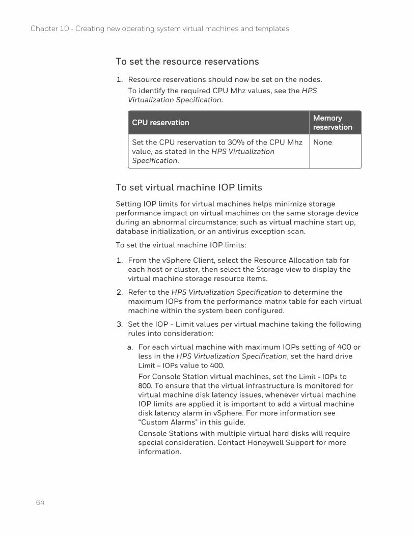
To set the resource reservations
1. Resource reservations should now be set on the nodes.To identify the required CPU Mhz values, see the HPS Virtualization Specification.
CPU reservation Memory reservation
Set the CPU reservation to 30% of the CPU Mhz value, as stated in the HPS Virtualization Specification.
None
To set virtual machine IOP limits
Setting IOP limits for virtual machines helps minimize storage performance impact on virtual machines on the same storage device during an abnormal circumstance; such as virtual machine start up, database initialization, or an antivirus exception scan.
To set the virtual machine IOP limits:
1. From the vSphere Client, select the Resource Allocation tab for each host or cluster, then select the Storage view to display the virtual machine storage resource items.
2. Refer to the HPS Virtualization Specification to determine the maximum IOPs from the performance matrix table for each virtual machine within the system been configured.
3. Set the IOP - Limit values per virtual machine taking the following rules into consideration:
a. For each virtual machine with maximum IOPs setting of 400 or less in the HPS Virtualization Specification, set the hard drive Limit – IOPs value to 400.For Console Station virtual machines, set the Limit - IOPs to 800. To ensure that the virtual infrastructure is monitored for virtual machine disk latency issues, whenever virtual machine IOP limits are applied it is important to add a virtual machine disk latency alarm in vSphere. For more information see “Custom Alarms" in this guide.Console Stations with multiple virtual hard disks will require special consideration. Contact Honeywell Support for more information.
64
Chapter 10 - Creating new operating system virtual machines and templates
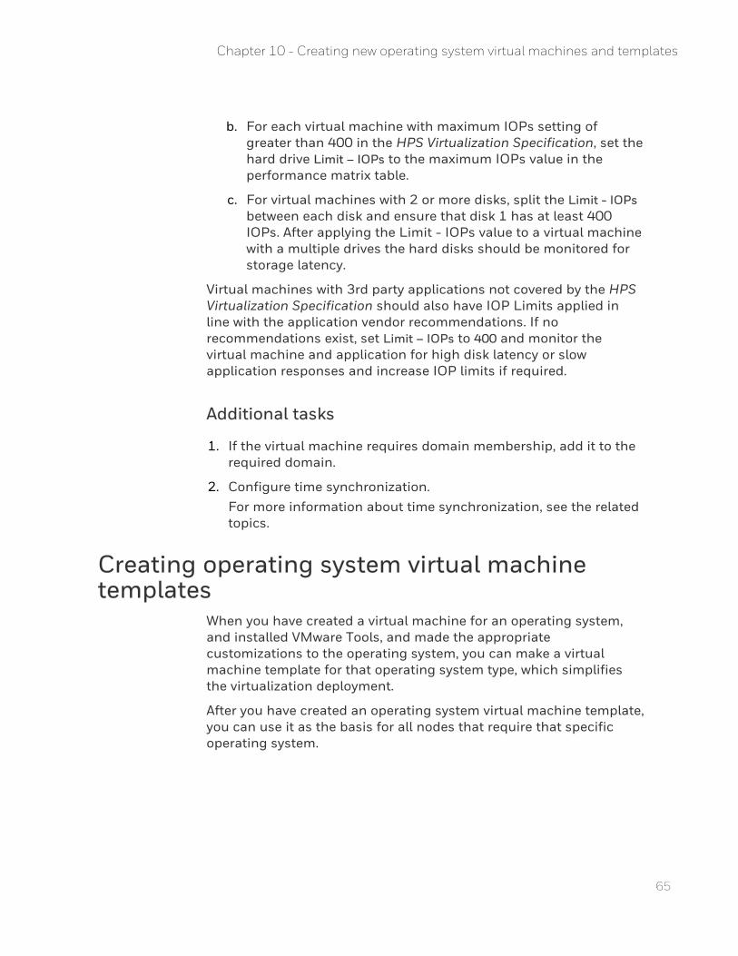
65
b. For each virtual machine with maximum IOPs setting of greater than 400 in the HPS Virtualization Specification, set the hard drive Limit – IOPs to the maximum IOPs value in the performance matrix table.
c. For virtual machines with 2 or more disks, split the Limit - IOPs between each disk and ensure that disk 1 has at least 400 IOPs. After applying the Limit - IOPs value to a virtual machine with a multiple drives the hard disks should be monitored for storage latency.
Virtual machines with 3rd party applications not covered by the HPS Virtualization Specification should also have IOP Limits applied in line with the application vendor recommendations. If no recommendations exist, set Limit – IOPs to 400 and monitor the virtual machine and application for high disk latency or slow application responses and increase IOP limits if required.
Additional tasks
1. If the virtual machine requires domain membership, add it to the required domain.
2. Configure time synchronization.For more information about time synchronization, see the related topics.
Creating operating system virtual machine templates
When you have created a virtual machine for an operating system, and installed VMware Tools, and made the appropriate customizations to the operating system, you can make a virtual machine template for that operating system type, which simplifies the virtualization deployment.
After you have created an operating system virtual machine template, you can use it as the basis for all nodes that require that specific operating system.
Chapter 10 - Creating new operating system virtual machines and templates
ATTENTION: Honeywell recommends that you do not use the Guest Customization when deploying from a template. As part of the process for preparing the virtual machine template, you needed to create a sysprep.xml file and store this file on the Utility virtual hard disk. This file ensures that the sysprep process runs correctly when the virtual machine is first powered on after deployment from a template.
n vSphere Virtual Machine Administration
To create operating system virtual machine templates for Windows Server and Windows OS
1. Copy the sysprep.xml file from the Utility virtual hard disk to the C:\Windows\system32\sysprep folder. Administrator privileges is required for this step.
2. Remove the Utility virtual hard disk from the virtual machine before converting it to a template.
a. Shutdown the virtual machine.To be able to remove the virtual hard disk, you need to shutdown the virtual machine first. If you don’t shutdown the virtual machine, the operating system on the virtual machine is left in a state that may cause problems with vDR backups.
b. In the vSphere client, right-click on the virtual machine and click Edit Settings.
c. Select the last Hard Disk in the list (this should be the Utility disk) and then click Remove. Select the Remove from virtual machine and delete files from disk option button.
d. Click OK to complete the removal process. e. Ensure that no media is mounted in the DVD/CD drive of the
virtual machine. 3. Convert the virtual machine into a template.
a. If you require a virtual machine that can be updated in the future and can be converted into an updated virtual machine template, shutdown the virtual machine and then create a clone of the virtual machine. A clone of the virtual machine will allow you to maintain and update the virtual machine, and create an updated template at a later date.
b. Restart the virtual machine.
66
Chapter 10 - Creating new operating system virtual machines and templates

67
c. Log on as ExperionAdmin, for virtual machines where the operating system was installed using the Experion System Initialization media, or an account with Administrator privileges, for virtual machines where the operating system was installed using Microsoft media.
d. Ensure that the sysprep.xml file has been copied into the C:\Windows\system32\sysprep folder.
e. Open a Command Prompt with Administrator privileges, and run the following commands:CD "Windows\system32\sysprep"sysprep /generalize /oobe /shutdown /unattend:sysprep.xml
The Windows operating system will shut down and prepare itself to run sysprep when it next starts up.
f. Ensure the virtual machine is shutdown. g. In the vSphere Client (in the Hosts and Clusters view), right-click
on the virtual machines and choose TemplateConvert to Template.
h. Change to the VMs and Templates view. i. Ensure that the template appears after the conversion.
The template does not appear in the Hosts and Clusters view.
Chapter 10 - Creating new operating system virtual machines and templates

68
Chapter 10 - Creating new operating system virtual machines and templates
CHAPTER
11 MANAGING SERVER LICENSES
Experion licensing provides functionality to let you view or change the license options for your server, as well as highlighting the differences between an old and a new license prior to installation.
In this section:
Viewing a server license 70
Exporting server licenses 70
Changing or comparing the Experion license 71
69
Viewing a server licenseYou can view or export the details of a license for a single server.
To view the license details for a server
1. From Configuration Studio, select a server in the network tree. 2. From the Server Tasks group, choose View License.
The View License display appears.
3. Use the filters provided at the top of the display to change the view of the data:
l All (default view) shows the complete list of license options, including those that are not licensed to this server
l Licensed shows only the options that are licensed to this server
From the View License display you can also Export the license for a single server. See “Exporting server licenses” for more information.
TIP: A Status zone at the top of the View License display will inform you if any of the following situations have occurred:
l A change has occurred that requires manual user intervention
l A license has been applied while you have been working in the License Utility
The Status zone also provides information about the active and the new license plus any recommended next steps, such as how to activate a new license.
Exporting server licensesYou can export the license details for a single server, or for all servers on a system. When you export the license details, they are saved in a .CSV file, which can be viewed in Microsoft Excel for detailed analysis. If you have a new license awaiting activation for the server, those details are exported. Otherwise, it is the active license details that is contained in the .CSV file.
70
Chapter 11 - Managing server licenses
71
When you select the server for which you want to export a license, you are actually exporting the primary server license details. If there is more than one primary server, details for all primaries are exported and presented in separate columns in the .CSV file.
To export the license details for a single server
1. From Configuration Studio, select the server you wish to work with.
2. From the Server Tasks list, choose Export License.The Save As dialog appears, prompting you for a name for the file and the location to save the license .CSV file.
To export the license details for all servers on a system
1. From Configuration Studio, click on the system name. 2. From the System Tasks list, choose Export server licenses.
The Export Server License dialog appears, where you can choose to export the licenses for all servers on this system, or just a selection of the servers. Any servers for which you cannot export a license will be greyed out.
3. Select the servers for which you want to export license details, then click Export.The Save As dialog appears, prompting you for a name for the file and the location to save the license .CSV file. The license details for all selected servers are contained in the same file, in separate columns.
Changing or comparing the Experion licenseThis section describes how to compare the details of a new Experion license with the current license, and how to apply a new license.
Prerequisites
n The new Experion license file.
n If you are planning a license change, it is recommended that you perform a backup of your system.
Chapter 11 - Managing server licenses
n Some major license changes require you to run the setup program from Experion Application DVD. The setup program will notify you if this is the case.
To change or compare the license on a server
1. From Configuration Studio, select the server on which you want to install the license.
2. From the Server Tasks list, choose Change or Compare License.The Change or Compare License display appears.
3. Find and select the new license file, then click Open.The License Comparison display appears, listing details of the new license and the current license so you can compare the differences between them and decide whether or not to apply the new license. Any differences in the new license, such as an option being removed or a number of items reduced, are highlighted.
4. To apply the new license to this server, click Apply.A confirmation dialog is displayed.
TIP: If there are any options that mean the license cannot be applied, the Apply button is disabled, and a tooltip appears describing the issue that need to be resolved before the license can be applied.Any unusual changes that occur as a result of the license change will be highlighted in the confirmation dialog.If, for some reason, the new license cannot be applied, an error message is displayed.
5. Click Yes to accept to acknowledge the confirmation dialog and apply the license.The View License display appears, providing details of the license that has just been applied, and informing you of the recommended next steps.
72
Chapter 11 - Managing server licenses
CHAPTER
12 SYSTEM ADMINISTRATION OF THE VIRTUALIZATION ENVIRONMENT
In this section:
Configuring the virtual machine load order 74
About starting and shutting down virtual machines 76
About suspending and resuming virtual machines 77
About snapshots 79
Changing virtual machine settings 85
Monitoring the virtualization environment 86
Monitoring the virtualization infrastructure from Station 92
Using vMotion in the Experion virtualization environment 94
Shared storage maintenance 95
Moving a USB security device to a new ESXi host 96
73
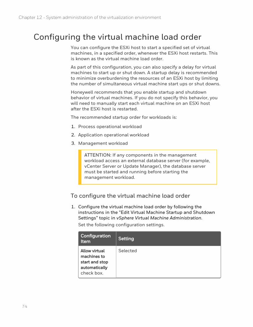
Configuring the virtual machine load orderYou can configure the ESXi host to start a specified set of virtual machines, in a specified order, whenever the ESXi host restarts. This is known as the virtual machine load order.
As part of this configuration, you can also specify a delay for virtual machines to start up or shut down. A startup delay is recommended to minimize overburdening the resources of an ESXi host by limiting the number of simultaneous virtual machine start ups or shut downs.
Honeywell recommends that you enable startup and shutdown behavior of virtual machines. If you do not specify this behavior, you will need to manually start each virtual machine on an ESXi host after the ESXi host is restarted.
The recommended startup order for workloads is:
1. Process operational workload
2. Application operational workload
3. Management workload
ATTENTION: If any components in the management workload access an external database server (for example, vCenter Server or Update Manager), the database server must be started and running before starting the management workload.
To configure the virtual machine load order
1. Configure the virtual machine load order by following the instructions in the “Edit Virtual Machine Startup and Shutdown Settings” topic in vSphere Virtual Machine Administration.Set the following configuration settings.
Configuration Item Setting
Allow virtual machines to start and stop automatically check box.
Selected
74
Chapter 12 - System administration of the virtualization environment
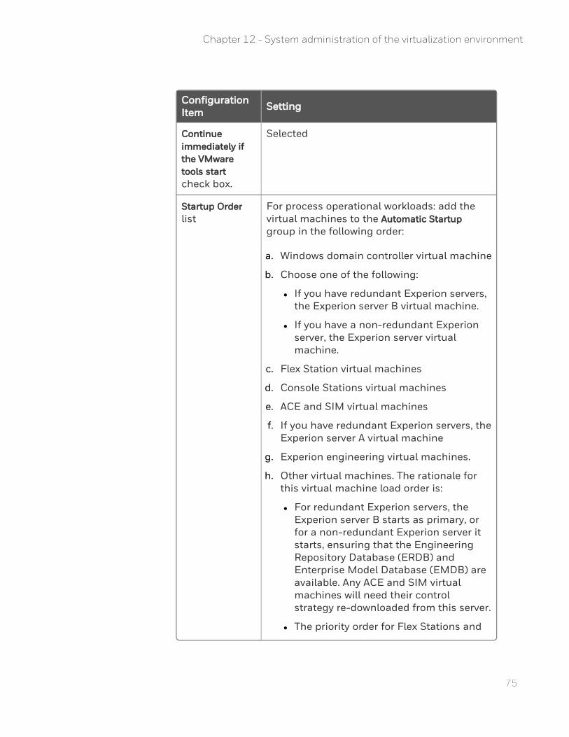
75
Configuration Item Setting
Continue immediately if the VMware tools start check box.
Selected
Startup Order list
For process operational workloads: add the virtual machines to the Automatic Startup group in the following order:
a. Windows domain controller virtual machine
b. Choose one of the following:
l If you have redundant Experion servers, the Experion server B virtual machine.
l If you have a non-redundant Experion server, the Experion server virtual machine.
c. Flex Station virtual machines
d. Console Stations virtual machines
e. ACE and SIM virtual machines
f. If you have redundant Experion servers, the Experion server A virtual machine
g. Experion engineering virtual machines.
h. Other virtual machines. The rationale for this virtual machine load order is:
l For redundant Experion servers, the Experion server B starts as primary, or for a non-redundant Experion server it starts, ensuring that the Engineering Repository Database (ERDB) and Enterprise Model Database (EMDB) are available. Any ACE and SIM virtual machines will need their control strategy re-downloaded from this server.
l The priority order for Flex Stations and
Chapter 12 - System administration of the virtualization environment
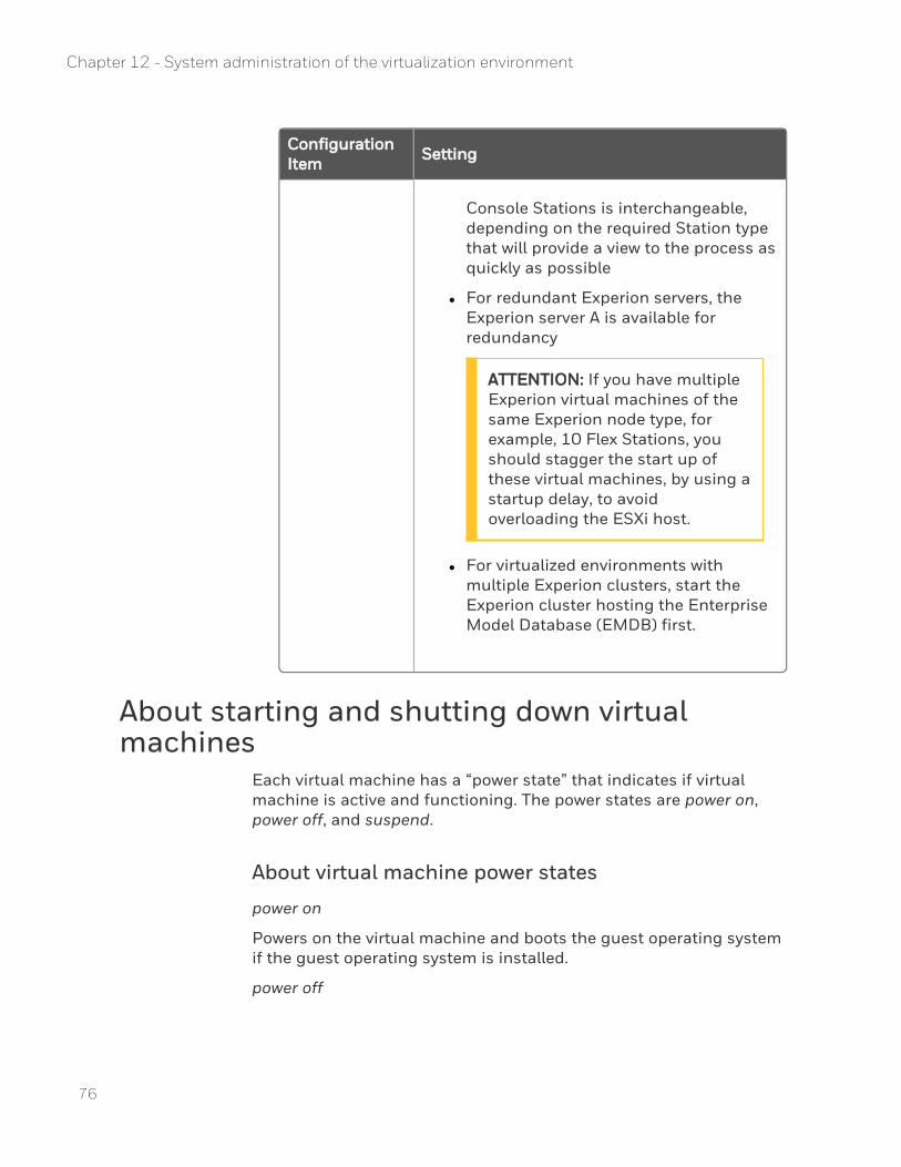
Configuration Item Setting
Console Stations is interchangeable, depending on the required Station type that will provide a view to the process as quickly as possible
l For redundant Experion servers, the Experion server A is available for redundancy
ATTENTION: If you have multiple Experion virtual machines of the same Experion node type, for example, 10 Flex Stations, you should stagger the start up of these virtual machines, by using a startup delay, to avoid overloading the ESXi host.
l For virtualized environments with multiple Experion clusters, start the Experion cluster hosting the Enterprise Model Database (EMDB) first.
About starting and shutting down virtual machines
Each virtual machine has a “power state” that indicates if virtual machine is active and functioning. The power states are power on, power off, and suspend.
About virtual machine power states
power on
Powers on the virtual machine and boots the guest operating system if the guest operating system is installed.
power off
76
Chapter 12 - System administration of the virtualization environment
77
Powers off the virtual machine. The virtual machine does not attempt to shutdown the guest operating system gracefully.
ATTENTION: The 'power off' option has the same effect as removing power from a physical machine and should be used sparingly. The preferred method to shut down a guest operating system is from the Windows Start menu, using the Shut Down option within the guest machine, or using the Shut Down Guest option in vCenter Server.
suspend
Pauses the virtual machine activity. All virtual machine operations are frozen until you issue a resume command.
resume
Releases a virtual machine from the suspend state.
reset
Shuts down the guest operating system and restarts it.
For more information about these power states and to understand how to transition between states, see “Managing Virtual Machines” in vSphere Virtual Machine Administration.
About suspending and resuming virtual machines
The suspend and resume feature is useful when you want to save the current state of a virtual machine, and hold the operation of the virtual machine. You can later resume the virtual machine to running and in the same state that the virtual machine was in when it was suspended.
ATTENTION: Suspending and resuming virtual machines is only supported for off-process usage.
Suspend and resume can be useful when testing. For example, if a fault or error is detected, the virtual machine can be placed into a suspend state that can allow you to delay the investigation of the error, holding the virtual machine in its current state until you are ready to resume.
Chapter 12 - System administration of the virtualization environment
The main consideration when suspending multiple Experion virtual machines, is that communication between virtual machines (for example, redundant Experion servers, Experion servers communicating with Flex Stations, and so on), will likely have failed on the non-suspended virtual machine, and the virtual machine that was suspended, may take some time to determine this state when resuming. If only a subset of Experion virtual machines are suspended, the state between the Experion virtual machines will be inconsistent. If all Experion virtual machines are to be suspended, consider shutting them down instead.
When Experion or Engineering Repository database (ERDB)) or manually (such as retry for Station connections, or manual synchronization for redundant Experion servers).Experion virtual machines should reconnect either automatically when available (such as DSA, Console Stations, or Engineering Repository database (ERDB)) or manually (such as retry for Station connections, or manual synchronization for redundant Experion servers).
Honeywell recommends that you close applications that are communicating across the network. However, as this is not always possible, here are some observations related to suspending and resuming Experion virtual machines:
n Redundant Experion serversAfter resuming, you will need to synchronize the Experion servers.If both servers were suspended, resume the virtual machines in the opposite order to which they were suspended.
n Flex StationsAfter resuming, you will need to manually reconnect to the Experion server.If the Experion server virtual machines were suspended at same time as Flex Station, resume the Flex Station virtual machine after resuming the Experion server virtual machines.
n Console StationsAfter resuming, each console station will need to synchronize with Experion servers; this should occur automatically.If the Experion server virtual machines were suspended at same time as the Console Stations, resume the Console Station virtual machine after resuming the Experion server virtual machines.
n ACE, SIM-ACE, SIM-C200, and SIM-C300 nodes
78
Chapter 12 - System administration of the virtualization environment
79
After resuming, you may need to download their strategies if they have been changed at the server whilst this node has been suspended.If the Experion server virtual machines were suspended at same time as these nodes, resume these node virtual machines after resuming the Experion server virtual machines.
n Engineering nodesAfter resuming, restart Configuration Studio to ensure it has a valid connection to the Experion servers.If the Experion server virtual machines were suspended at same time as these nodes, resume these node virtual machines after resuming the Experion server virtual machines.
n DSAAfter resuming:
l DSA should automatically reconnect once Experion servers have resumed.
l You may need to download system and asset models if they have been changed while some server nodes have been suspended.
n Process and SCADA controllersAfter resuming Experion servers and Console Stations, controllers should reconnect.
About snapshotsA snapshot captures the entire state of a virtual machine at the time you take a snapshot, including virtual machine settings, disk state, and optionally, memory states.
Before considering the use of snapshots ensure that you understand how snapshots work and the recommended best practices for virtual machine snapshots in the VMware environment. Refer to the following VMware documentation for more information:
n vSphere Virtual Machine Administration
n VMware KB article 1025279 – “Best practices for virtual machine snapshots in the VMware environment”
Chapter 12 - System administration of the virtualization environment
The snapshot feature is useful when you want to create restoration points during a linear process, such as installing updates or patches, so that you can revert to an earlier state in the event of failure. The retention of snapshots for extended periods of time is not recommended as it may impact system performance. After successfully performing the patch of install activity that required the use of the snapshot it is recommended that the snapshot be removed.
When reverting a virtual machine from an earlier snapshot, the virtual machine returns to the state that it was when the snapshot was taken. Certain types of activity occurring within the virtual machine at the time of the snapshot might result in unexpected behavior when reverting back to the snapshot. For example, if you were to take a snapshot of a virtual machine while it is communicating with another virtual machine (Experion node), and if you revert to this snapshot, the reverted virtual machine may attempt to complete the communication with the other virtual machine and cause possible communication errors between the virtual machines.
Snapshots can be taken with or without the virtual machine memory. When reverting to a snapshot that is:
n Created without the virtual machine memory – the virtual machine will perform a cold boot, that is, the Virtual machine will behave the same as if it was powering on from the off state.
n Created with virtual machine memory – the virtual machine will return to the exact run state that it was at, at the time of snapshot creation. There will be no virtual machine boot sequence and all applications running at time of snapshot will be in the same state.
When reverting to a snapshot where the virtual machine memory was saved this can result in unexpected behavior to the point that the virtual machine is unusable. This is due to applications that were communicating over the network to another machine or device in an uncertain state. To avoid this, the instructions below can help ensure each Experion node type is in a safe state prior to making a snapshot that includes the virtual machine image.
For this reason, Honeywell suggests that snapshots with virtual machine memory should be used in a small set of situations where the saved virtual machine memory is important (for example, troubleshooting with Honeywell TAC). In the majority of cases, the preferred solution is to require a restart of the VM, similar to that for
80
Chapter 12 - System administration of the virtualization environment
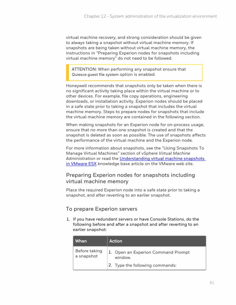
81
virtual machine recovery, and strong consideration should be given to always taking a snapshot without virtual machine memory. If snapshots are being taken without virtual machine memory, the instructions in “Preparing Experion nodes for snapshots including virtual machine memory” do not need to be followed.
ATTENTION: When performing any snapshot ensure that Quiesce guest file system option is enabled.
Honeywell recommends that snapshots only be taken when there is no significant activity taking place within the virtual machine or to other devices. For example, file copy operations, engineering downloads, or installation activity. Experion nodes should be placed in a safe state prior to taking a snapshot that includes the virtual machine memory. Steps to prepare nodes for snapshots that include the virtual machine memory are contained in the following section.
When making snapshots for an Experion node for on-process usage, ensure that no more than one snapshot is created and that the snapshot is deleted as soon as possible. The use of snapshots affects the performance of the virtual machine and the Experion node.
For more information about snapshots, see the “Using Snapshots To Manage Virtual Machines” section of vSphere Virtual Machine Administration or read the Understanding virtual machine snapshots in VMware ESX knowledge base article on the VMware web site.
Preparing Experion nodes for snapshots including virtual machine memoryPlace the required Experion node into a safe state prior to taking a snapshot, and after reverting to an earlier snapshot.
To prepare Experion servers
1. If you have redundant servers or have Console Stations, do the following before and after a snapshot and after reverting to an earlier snapshot:
When Action
Before taking a snapshot
1. Open an Experion Command Prompt window.
2. Type the following commands:
Chapter 12 - System administration of the virtualization environment
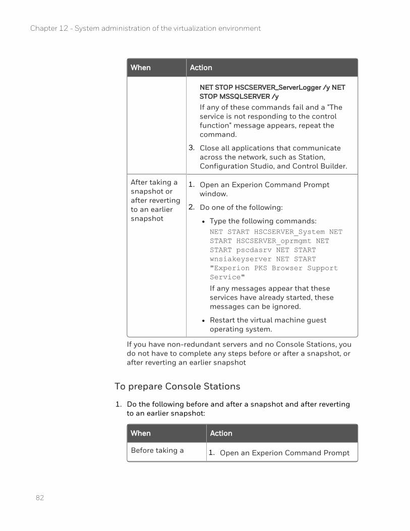
When Action
NET STOP HSCSERVER_ServerLogger /y NET STOP MSSQLSERVER /y
If any of these commands fail and a "The service is not responding to the control function" message appears, repeat the command.
3. Close all applications that communicate across the network, such as Station, Configuration Studio, and Control Builder.
After taking a snapshot or after reverting to an earlier snapshot
1. Open an Experion Command Prompt window.
2. Do one of the following:
l Type the following commands:NET START HSCSERVER_System NET START HSCSERVER_oprmgmt NET START pscdasrv NET START wnsiakeyserver NET START "Experion PKS Browser Support Service"
If any messages appear that these services have already started, these messages can be ignored.
l Restart the virtual machine guest operating system.
If you have non-redundant servers and no Console Stations, you do not have to complete any steps before or after a snapshot, or after reverting an earlier snapshot
To prepare Console Stations
1. Do the following before and after a snapshot and after reverting to an earlier snapshot:
When Action
Before taking a 1. Open an Experion Command Prompt
82
Chapter 12 - System administration of the virtualization environment
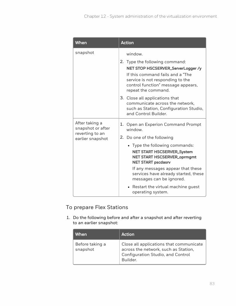
83
When Action
snapshot window.
2. Type the following command:NET STOP HSCSERVER_ServerLogger /y
If this command fails and a "The service is not responding to the control function" message appears, repeat the command.
3. Close all applications that communicate across the network, such as Station, Configuration Studio, and Control Builder.
After taking a snapshot or after reverting to an earlier snapshot
1. Open an Experion Command Prompt window.
2. Do one of the following
l Type the following commands:NET START HSCSERVER_System NET START HSCSERVER_oprmgmt NET START pscdasrv
If any messages appear that these services have already started, these messages can be ignored.
l Restart the virtual machine guest operating system.
To prepare Flex Stations
1. Do the following before and after a snapshot and after reverting to an earlier snapshot:
When Action
Before taking a snapshot
Close all applications that communicate across the network, such as Station, Configuration Studio, and Control Builder.
Chapter 12 - System administration of the virtualization environment
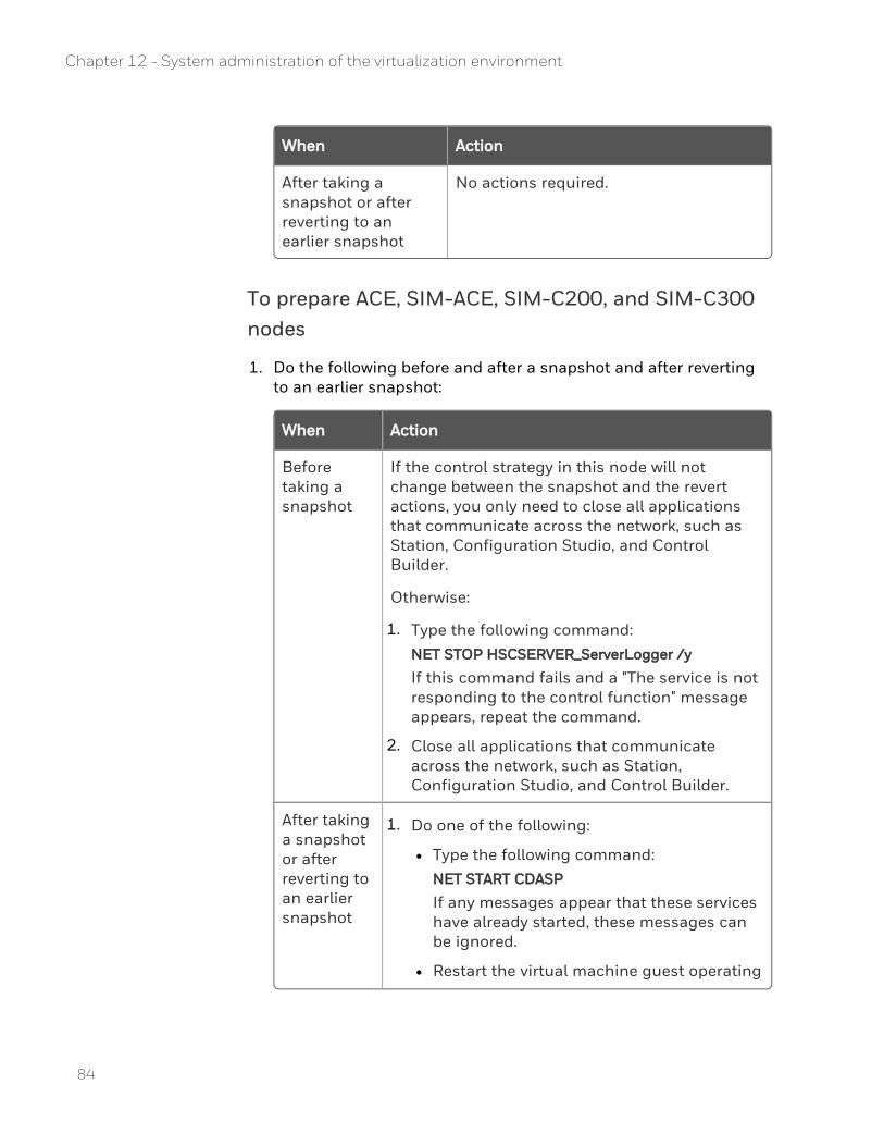
When Action
After taking a snapshot or after reverting to an earlier snapshot
No actions required.
To prepare ACE, SIM-ACE, SIM-C200, and SIM-C300 nodes
1. Do the following before and after a snapshot and after reverting to an earlier snapshot:
When Action
Before taking a snapshot
If the control strategy in this node will not change between the snapshot and the revert actions, you only need to close all applications that communicate across the network, such as Station, Configuration Studio, and Control Builder.
Otherwise:
1. Type the following command:NET STOP HSCSERVER_ServerLogger /y
If this command fails and a "The service is not responding to the control function" message appears, repeat the command.
2. Close all applications that communicate across the network, such as Station, Configuration Studio, and Control Builder.
After taking a snapshot or after reverting to an earlier snapshot
1. Do one of the following:
l Type the following command:NET START CDASP
If any messages appear that these services have already started, these messages can be ignored.
l Restart the virtual machine guest operating
84
Chapter 12 - System administration of the virtualization environment
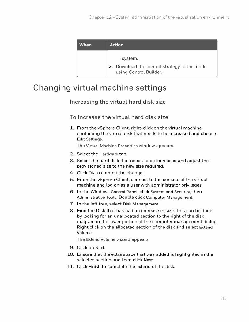
85
When Action
system.
2. Download the control strategy to this node using Control Builder.
Changing virtual machine settings
Increasing the virtual hard disk size
To increase the virtual hard disk size
1. From the vSphere Client, right-click on the virtual machine containing the virtual disk that needs to be increased and choose Edit Settings.The Virtual Machine Properties window appears.
2. Select the Hardware tab. 3. Select the hard disk that needs to be increased and adjust the
provisioned size to the new size required. 4. Click OK to commit the change. 5. From the vSphere Client, connect to the console of the virtual
machine and log on as a user with administrator privileges. 6. In the Windows Control Panel, click System and Security, then
Administrative Tools. Double click Computer Management. 7. In the left tree, select Disk Management. 8. Find the Disk that has had an increase in size. This can be done
by looking for an unallocated section to the right of the disk diagram in the lower portion of the computer management dialog. Right click on the allocated section of the disk and select Extend Volume.The Extend Volume wizard appears.
9. Click on Next. 10. Ensure that the extra space that was added is highlighted in the
selected section and then click Next. 11. Click Finish to complete the extend of the disk.
Chapter 12 - System administration of the virtualization environment
Monitoring the virtualization environmentThe vSphere virtual environment provides built-in tools that provide the ability to monitor the resource usage of the virtual infrastructure and signal alarms as to the status of the virtual infrastructure when thresholds are crossed. It is important to understand these tools so that the health of the virtual environment is maintained.
It is also possible to use the System Status Display in Experion Station to monitor the various virtual infrastructure status alarms described in “About system status”.
The virtual environment may require monitoring when operators using Experion experience slow display call-up or inconsistent refresh rates on displays. Using the Station Display Performance table in the Experion Station Specification document as a guide, which can be found on the Honeywell Process Solutions web site, monitor Station display update rate and display call up times. Compare the specification limitations and call up times to the virtual Station performance and ensure that performance is within the specification limits.
Engineering tools usage can also give an indication that the virtual environment may require monitoring. When the Experion engineering tools are used, any inconsistency in the time to perform actions indicate that the resource usage of the virtual infrastructure may not be optimal.
To rectify performance issues seen when comparing update rate and call-up times with the specification and when engineering tools show inconsistency, see the following resource usage and system status topics.
About resource usageVirtual infrastructure resource usage is monitored using the performance charts in the vSphere Client. These charts help administrators view the resource usage and performance indicators in the virtual environment. Guidance on the usage of both the overview performance charts and the advanced performance charts are provided in the “Monitoring Inventory Objects with Performance Charts” section.
The five performance areas that define the health of the virtual environment are:
n CPU
n disk I/O
86
Chapter 12 - System administration of the virtualization environment
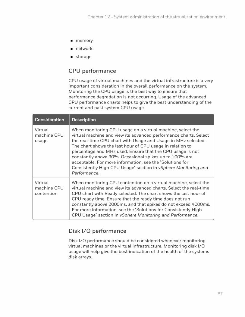
87
n memory
n network
n storage
CPU performance
CPU usage of virtual machines and the virtual infrastructure is a very important consideration in the overall performance on the system. Monitoring the CPU usage is the best way to ensure that performance degradation is not occurring. Usage of the advanced CPU performance charts helps to give the best understanding of the current and past system CPU usage.
Consideration Description
Virtual machine CPU usage
When monitoring CPU usage on a virtual machine, select the virtual machine and view its advanced performance charts. Select the real-time CPU chart with Usage and Usage in MHz selected. The chart shows the last hour of CPU usage in relation to percentage and MHz used. Ensure that the CPU usage is not constantly above 90%. Occasional spikes up to 100% are acceptable. For more information, see the "Solutions for Consistently High CPU Usage" section in vSphere Monitoring and Performance.
Virtual machine CPU contention
When monitoring CPU contention on a virtual machine, select the virtual machine and view its advanced charts. Select the real-time CPU chart with Ready selected. The chart shows the last hour of CPU ready time. Ensure that the ready time does not run constantly above 2000ms, and that spikes do not exceed 4000ms. For more information, see the "Solutions for Consistently High CPU Usage" section in vSphere Monitoring and Performance.
Disk I/O performance
Disk I/O performance should be considered whenever monitoring virtual machines or the virtual infrastructure. Monitoring disk I/O usage will help give the best indication of the health of the systems disk arrays.
Chapter 12 - System administration of the virtualization environment
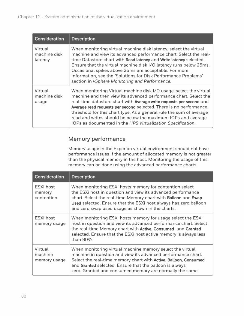
Consideration Description
Virtual machine disk latency
When monitoring virtual machine disk latency, select the virtual machine and view its advanced performance chart. Select the real-time Datastore chart with Read latency and Write latency selected. Ensure that the virtual machine disk I/O latency runs below 25ms. Occasional spikes above 25ms are acceptable. For more information, see the "Solutions for Disk Performance Problems" section in vSphere Monitoring and Performance.
Virtual machine disk usage
When monitoring Virtual machine disk I/O usage, select the virtual machine and then view its advanced performance chart. Select the real-time datastore chart with Average write requests per second and Average read requests per second selected. There is no performance threshold for this chart type. As a general rule the sum of average read and writes should be below the maximum IOPs and average IOPs as documented in the HPS Virtualization Specification.
Memory performance
Memory usage in the Experion virtual environment should not have performance issues if the amount of allocated memory is not greater than the physical memory in the host. Monitoring the usage of this memory can be done using the advanced performance charts.
Consideration Description
ESXi host memory contention
When monitoring ESXi hosts memory for contention select the ESXi host in question and view its advanced performance chart. Select the real-time Memory chart with Balloon and Swap Used selected. Ensure that the ESXi host always has zero balloon and zero swap used usage as shown in the charts.
ESXi host memory usage
When monitoring ESXi hosts memory for usage select the ESXi host in question and view its advanced performance chart. Select the real-time Memory chart with Active, Consumed and Granted selected. Ensure that the ESXi host active memory is always less than 90%.
Virtual machine memory usage
When monitoring virtual machine memory select the virtual machine in question and view its advanced performance chart. Select the real-time memory chart with Active, Balloon, Consumed and Granted selected. Ensure that the balloon is always zero. Granted and consumed memory are normally the same.
88
Chapter 12 - System administration of the virtualization environment
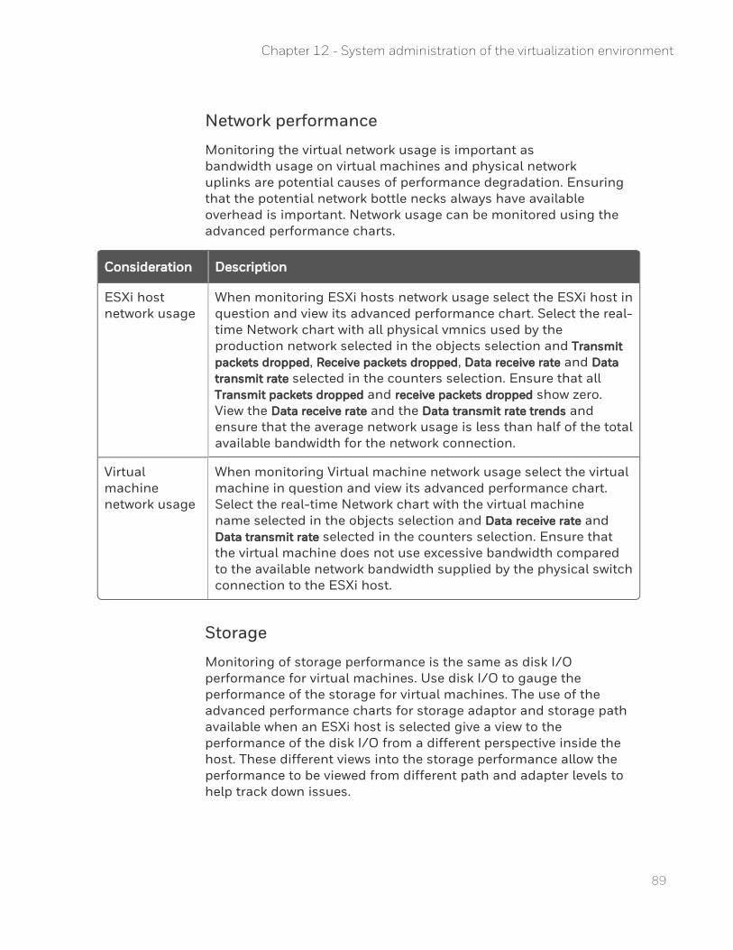
89
Network performance
Monitoring the virtual network usage is important as bandwidth usage on virtual machines and physical network uplinks are potential causes of performance degradation. Ensuring that the potential network bottle necks always have available overhead is important. Network usage can be monitored using the advanced performance charts.
Consideration Description
ESXi host network usage
When monitoring ESXi hosts network usage select the ESXi host in question and view its advanced performance chart. Select the real-time Network chart with all physical vmnics used by the production network selected in the objects selection and Transmit packets dropped, Receive packets dropped, Data receive rate and Data transmit rate selected in the counters selection. Ensure that all Transmit packets dropped and receive packets dropped show zero. View the Data receive rate and the Data transmit rate trends and ensure that the average network usage is less than half of the total available bandwidth for the network connection.
Virtual machine network usage
When monitoring Virtual machine network usage select the virtual machine in question and view its advanced performance chart. Select the real-time Network chart with the virtual machine name selected in the objects selection and Data receive rate and Data transmit rate selected in the counters selection. Ensure that the virtual machine does not use excessive bandwidth compared to the available network bandwidth supplied by the physical switch connection to the ESXi host.
Storage
Monitoring of storage performance is the same as disk I/O performance for virtual machines. Use disk I/O to gauge the performance of the storage for virtual machines. The use of the advanced performance charts for storage adaptor and storage path available when an ESXi host is selected give a view to the performance of the disk I/O from a different perspective inside the host. These different views into the storage performance allow the performance to be viewed from different path and adapter levels to help track down issues.
Chapter 12 - System administration of the virtualization environment
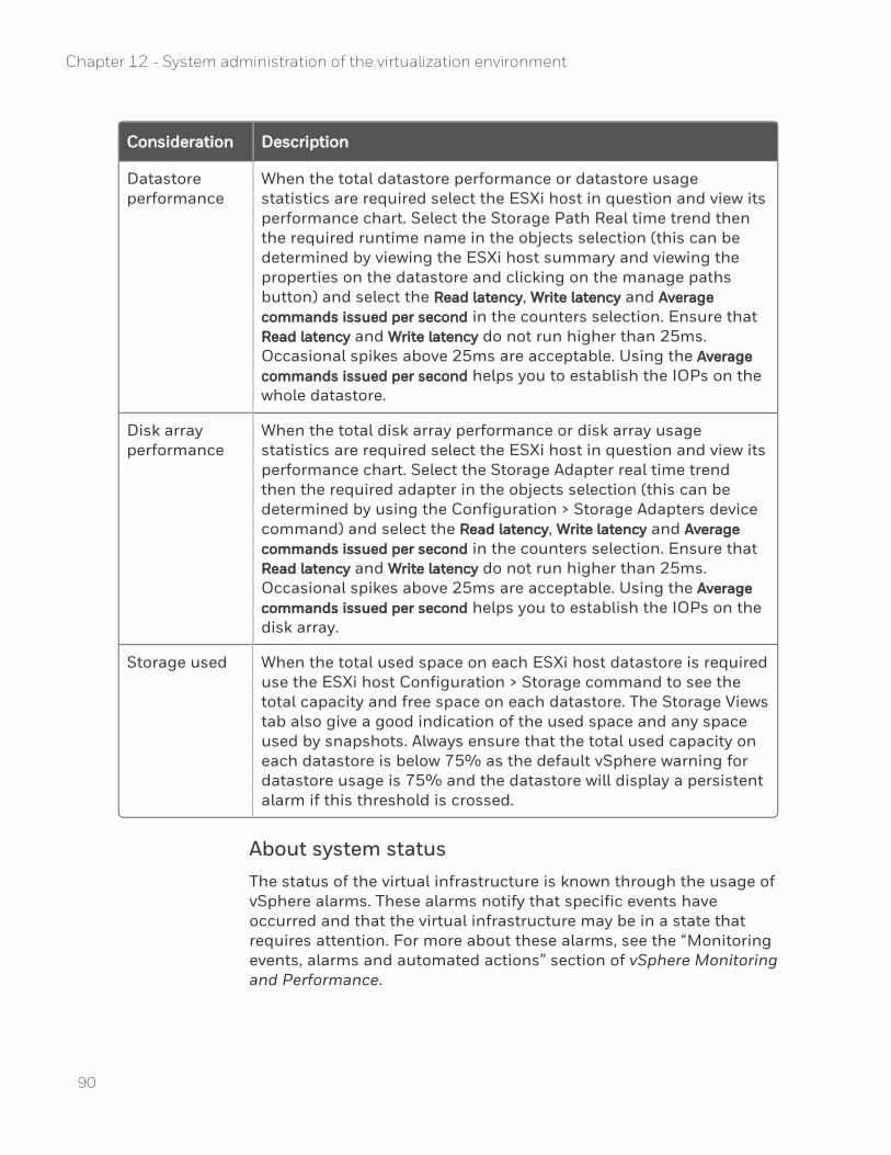
Consideration Description
Datastore performance
When the total datastore performance or datastore usage statistics are required select the ESXi host in question and view its performance chart. Select the Storage Path Real time trend then the required runtime name in the objects selection (this can be determined by viewing the ESXi host summary and viewing the properties on the datastore and clicking on the manage paths button) and select the Read latency, Write latency and Average commands issued per second in the counters selection. Ensure that Read latency and Write latency do not run higher than 25ms. Occasional spikes above 25ms are acceptable. Using the Average commands issued per second helps you to establish the IOPs on the whole datastore.
Disk array performance
When the total disk array performance or disk array usage statistics are required select the ESXi host in question and view its performance chart. Select the Storage Adapter real time trend then the required adapter in the objects selection (this can be determined by using the Configuration > Storage Adapters device command) and select the Read latency, Write latency and Average commands issued per second in the counters selection. Ensure that Read latency and Write latency do not run higher than 25ms. Occasional spikes above 25ms are acceptable. Using the Average commands issued per second helps you to establish the IOPs on the disk array.
Storage used When the total used space on each ESXi host datastore is required use the ESXi host Configuration > Storage command to see the total capacity and free space on each datastore. The Storage Views tab also give a good indication of the used space and any space used by snapshots. Always ensure that the total used capacity on each datastore is below 75% as the default vSphere warning for datastore usage is 75% and the datastore will display a persistent alarm if this threshold is crossed.
About system statusThe status of the virtual infrastructure is known through the usage of vSphere alarms. These alarms notify that specific events have occurred and that the virtual infrastructure may be in a state that requires attention. For more about these alarms, see the “Monitoring events, alarms and automated actions” section of vSphere Monitoring and Performance.
90
Chapter 12 - System administration of the virtualization environment

91
Standard Alarms
vCenter is installed with a number of default alarms that warn you of resource usage status. The list of alarms shown below should be used as a warning that Experion virtual machine performance is likely to be affected:
n Virtual machine CPU usage - Shows a warning at 75% and an alert at 90% - warns that the virtual machine is approaching its CPU limit. No action should be taken unless CPU is constantly reaching 100%
n Virtual machine memory usage - Shows a warning at 85% and an alert at 95% - warns that the virtual machine is actively using its allocated memory and the guest operating system could potential start to use swap files instead of memory. When virtual machine memory is above 95% for extended periods of time virtual machine memory should be increased.
n Host CPU usage - Shows warning at 75% and an alert at 90% - warns of ESXi host CPU constraints that may be detrimental to performance of the Experion virtual machines. Virtual machines should be moved off the ESXi host if host CPU usage exceeds 90% for extended periods of time.
n Host memory usage - Shows warning at 90% and an alert at 95% - warns of ESXi host memory constraints that could lead to ballooning and memory swapping of Experion virtual machines. ESXi host memory should be increased or virtual machines should be moved off the ESXi host if host memory exceeds 90% for extended periods of time.
Custom Alarms
The following alarm can be configured to warn that virtual machine performance is likely to be affected:
n Virtual machine CPU ready time - Set Alarm Type to monitor Virtual machines - Set trigger type to virtual machine CPU ready time (ms) - Set warning is above 1800 for 5 minutes and set alert is above 2000 for 5 minutes. This will warn of CPU contention on a virtual machine. When Console Stations are used in a large system where the number of Console Stations is approaching 20 this value should be reduced to set warning is above 800 for 5 minutes and set alert is above 1000 for 5 minutes.
Chapter 12 - System administration of the virtualization environment
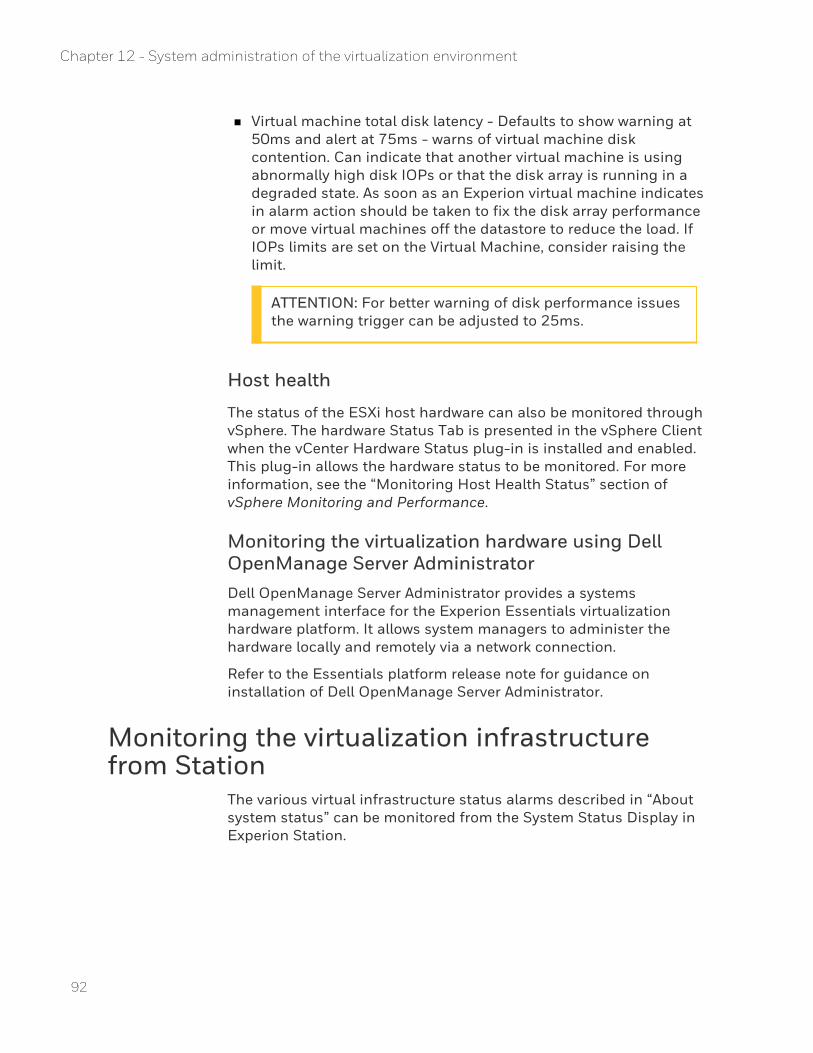
n Virtual machine total disk latency - Defaults to show warning at 50ms and alert at 75ms - warns of virtual machine disk contention. Can indicate that another virtual machine is using abnormally high disk IOPs or that the disk array is running in a degraded state. As soon as an Experion virtual machine indicates in alarm action should be taken to fix the disk array performance or move virtual machines off the datastore to reduce the load. If IOPs limits are set on the Virtual Machine, consider raising the limit.
ATTENTION: For better warning of disk performance issues the warning trigger can be adjusted to 25ms.
Host health
The status of the ESXi host hardware can also be monitored through vSphere. The hardware Status Tab is presented in the vSphere Client when the vCenter Hardware Status plug-in is installed and enabled. This plug-in allows the hardware status to be monitored. For more information, see the “Monitoring Host Health Status” section of vSphere Monitoring and Performance.
Monitoring the virtualization hardware using Dell OpenManage Server AdministratorDell OpenManage Server Administrator provides a systems management interface for the Experion Essentials virtualization hardware platform. It allows system managers to administer the hardware locally and remotely via a network connection.
Refer to the Essentials platform release note for guidance on installation of Dell OpenManage Server Administrator.
Monitoring the virtualization infrastructure from Station
The various virtual infrastructure status alarms described in “About system status” can be monitored from the System Status Display in Experion Station.
92
Chapter 12 - System administration of the virtualization environment
93
To configure the VMware vCenter Server
1. In the VMware vSphere Web Client Home page click vCenter. 2. From theInventory Lists click vCenterServers then click your
vCenter Server. 3. Click Manage>Settings>General>Edit>SNMP receivers and configure
two receivers by clicking the Enabled checkbox next to the second receiver and enter the following details:Primary Receiver URL: hostname or IP address of Experion Server AReceiver 2 URL: hostname or IP address of Experion Server BReceiver port: 162 (recommended UDP port number)Community string: public
To configure the Alarm Definitions
1. From the Manage page click Alarm Definitions. 2. To edit an existing alarm click that alarm then click Edit. 3. To add a new alarm click the + symbol. 4. Click General and use the following details to define:
Alarm name: Enter an appropriate name for new alarms onlyDescription: Enter an appropriate description for new alarms onlyMonitor: Select the infrastructure type to be monitored by this alarmMonitor for: Choose to monitor specific conditions or event.Enable this alarm: Enable this alarm within vCenter Server by clicking the checkbox.
5. Click Triggers and delete existing (X) or add (+) new triggers using the following details:Trigger if: Choose whether ANY or ALL of the following conditions will trigger this alarm.Trigger: Click the combobox and choose the required trigger from the drop down listOperator: Click the combobox and choose the required operator from the drop down listWarning Condition: Click the combobox and choose the required condition from the drop down listCritical Condition: Click the combobox and choose the required condition from the drop down list
Chapter 12 - System administration of the virtualization environment
6. For each alarm that is required to be seen in the System Status Display in Experion Station click Actions and add (+) one trigger; Honeywell recommends the following details:Action: Click the combobox and choose Send a notification trap.Configuration : leave blankOK>Warning: leave blankWarning> Critical: Click the combobox and choose Once
Critical>Warning: leave blankWarning>OK: leave blankRepeat actions every:Set to 0 minutes
7. Click Finish
To add a device for the vCenter Server in the Network Tree
1. Start Configuration Studio and connect to the System 2. In the Network tree add a new Switch Device with the following
details:Name: VCENTERSERVER (or as required)IP Address: IP Address of the vCenter ServerDescription: vCenter Server SNMP Provider (or as required)Read Community: publicLeave all other fields at default values.
3. Click OK
4. Assign an Associated Asset as required.
Using vMotion in the Experion virtualization environment
vMotion is a powerful feature of vSphere. It is a feature also known as live migration that allows a running virtual machine to be moved from one ESXi host to another ESXi host without having to power off the virtual machine.
This migration between two ESXi hosts occurs with no downtime and with no loss of network connectivity to the virtual machine. Using vMotion requires shared storage. Therefore, only virtual environments that have a storage area network (SAN) can support the use of vMotion.
94
Chapter 12 - System administration of the virtualization environment
95
ATTENTION: The current implementation of the Experion on-process virtual infrastructure does not use the clustering of ESXi hosts. Features like VMware DRS and VMware HA are not possible, and the use of vMotion is also limited. Without clustering, vMotion will only function correctly between ESXi hosts with the same series and same brand of physical CPU. For more information, see the “CPU Families and Feature Sets” section of the vSphere Datacenter Administration Guide.
Under normal running conditions, it is a requirement that Experion virtual machines stay on the ESXi host that have been provisioned for their resource needs. The advantage of vMotion is that Experion virtual machines that are critical can use vMotion to be moved to a different ESXi host and continue to run when a planned ESXi host upgrade or patch is applied. The destination ESXi host must have enough spare CPU and memory to support the added load of the virtual machine being migrated. The same virtual machine should be moved back to the original ESXi host after it is available again.
ATTENTION: In an on-process virtual system, redundant Experion servers should never be run on the same ESXi host. When using vMotion within your virtualization environment always remember this basic principle.
For more information about the vMotion configuration requirements, see the “Host configuration for vMotion” and “Virtual machine requirements for vMotion” sections of the vSphere Datacenter Administration Guide.
To use vMotion, see the “Migrate a Powered-On Virtual machine with vMotion” section of the vSphere Datacenter Administration Guide.
ATTENTION: Storage vMotion is not supported for on-process usage.
Shared storage maintenanceReview the planning considerations before updating shared storage device firmware or adding additional shared storage.
Chapter 12 - System administration of the virtualization environment
Updating shared storage firmware
Before updating the firmware on any shared storage devices, you must make a backup of all virtual machines stored on that shared storage device.
Depending on the shared storage device, it is important to know whether the shared storage device allows the data contained on it to be accessed during the firmware update process, and whether there are any restrictions or implications of doing so (such as reduced IOPs, increased latency, and so on). If access to the shared storage device is not available or is degraded during the firmware update process, all or some of the virtual machines that are stored on it may not be accessible during the firmware update. If these are critical virtual machines, these virtual machines will need to be run from an alternate location during the firmware update. If alternate storage for some or all of the virtual machines is required, you will need to plan for extra time to either take these virtual machines offline and move them to the new storage location, or to use Storage vMotion to move these virtual machines. Storage vMotion can take significantly longer to move virtual machines compared to the host-based vMotion application.
ATTENTION: Storage vMotion is only supported for off-process usage.
Moving a USB security device to a new ESXi host
If an Experion virtual machine requires a USB security device (dongle) and you use vMotion to move the virtual machine to a different ESXi host, you may need to move the USB security device.
n The storage area network (SAN) device must accessible from both ESXi hosts.
n Domain name server (DNS) references must be correct for both ESXi hosts, as the USB passthrough device uses the ESXi host DNS names and DNS resolution.
To move a USB security device to a new ESXi host
1. Ensure that the Experion server is running normally with no copy protection system alarms.
96
Chapter 12 - System administration of the virtualization environment
97
2. vMotion the Experion server virtual machine to the destination ESXi host.No copy protection system alarms should appear.
3. Remove the USB dongle from the original ESXi host and insert it in the destination ESXi host.A copy protection system alarm, stating that the server will be shutdown in 60 minutes, should appear.
4. Edit the virtual machine settings on the Experion server virtual machine and remove the existing USB device. Then, add the new USB device to the virtual machine.
ATTENTION: It may take several minutes for the USB device to be recognized by the destination ESXi host.
The Experion server recognizes the USB device and no additional copy protection system alarms appear.
Chapter 12 - System administration of the virtualization environment

98
Chapter 12 - System administration of the virtualization environment
CHAPTER
13 TUNING SYSTEM PERFORMANCE
The following topics describe how to tune system performance.
TIP: These topics are also applicable to Console Stations.
In this section:
Specialized terms 100
Tuning the Windows operating system 103
Optimizing the server's hard disk performance 104
Optimizing the server's memory usage 107
Network performance 109
Special considerations for Fault Tolerant Ethernet/EHG networks111
Optimizing other computer settings 113
Optimizing the scanning load 116
Monitoring the system 120
Monitoring performance 121
Monitoring System Health 128
99
Specialized termsThis section describes the components of the supervisory network and the features in Experion that affect reliability, system availability, and performance.
Performance refers to the speed with which a system reacts to a series of tasks, and the ability to perform those tasks in a reliable manner. There are two aspects of performance:
n Overall system performance. This type of performance is most affected by the configuration of drivers and related software that make up the system.
n Individual application/subsystem performance. This type of performance is typically configured through the use of software settings and hardware components.
Reliability and system availability are the primary concern of process control systems. The main goals are to make sure that the system is available to the user at any point it time, and that Experion is responsive and presents the correct data.
Network layersThe following figure shows how a process control system can contain several network layers: IO, Control, Supervisory, and Application.
100
Chapter 13 - Tuning system performance
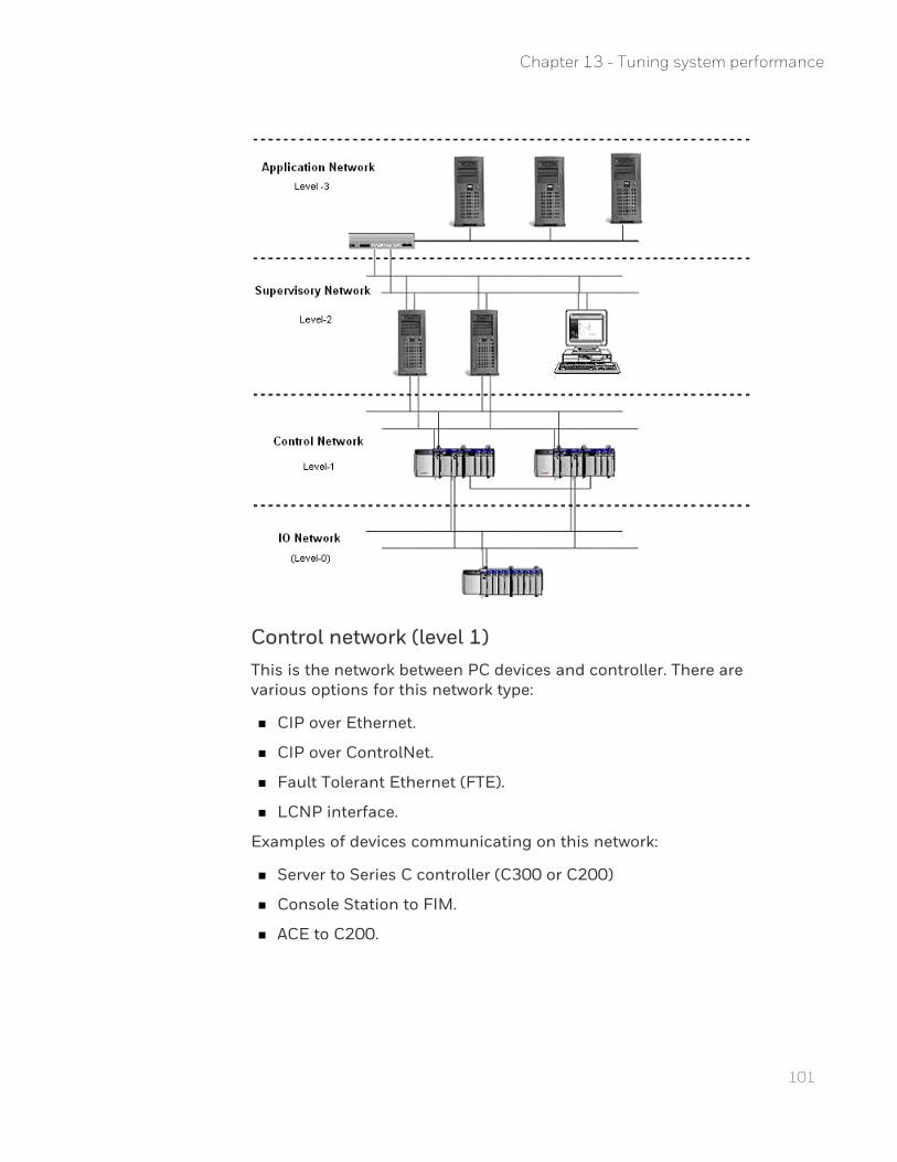
101
Control network (level 1)This is the network between PC devices and controller. There are various options for this network type:
n CIP over Ethernet.
n CIP over ControlNet.
n Fault Tolerant Ethernet (FTE).
n LCNP interface.
Examples of devices communicating on this network:
n Server to Series C controller (C300 or C200)
n Console Station to FIM.
n ACE to C200.
Chapter 13 - Tuning system performance
Supervisory network (level 2)This communication network is for the distribution of data between data collection devices (typically servers) and user interfaces. The options available for this network are:
n Ethernet
n Fault Tolerant Ethernet (FTE) (see the Attention below).
Examples of systems communicating over this network:
n Server to Console Station.
n Server to Flex Station.
n Server to ACE.
n Server to EHG.
Application network (level 3)This communication network is for applications that manage control devices but not necessary for control process itself. The options existing for this network:
n Ethernet.
n Fault Tolerant Ethernet (FTE) (see the Attention note below).
Examples of systems communicating over this network:
n @ssetMAX.
n ProfitMAX.
Business network (level 4, not shown)This communication network is for applications that interface between business systems and the control system. The options existing for this network:
n Ethernet.
n Fault Tolerant Ethernet (FTE) either a co-joined (combined level 1 control network and level 2 supervisory network) or a level 2 network. When co‐joined, it is physically one network, but logically separated by the use of subnet masks.
Examples of systems communicating over this network:
n OptiVISION.
102
Chapter 13 - Tuning system performance
103
Tuning the Windows operating systemOperating system (or kernel) tuning changes the way the operating system assigns process priorities.
ATTENTION: If the computer was installed using the Experion Initialization Media, the operating system is already tuned for operations.
To tune the operating system as described in this section, you need to log on to a Windows account with administrative privileges.
Setting the processor schedulingWindows manages processor resources automatically. It can allocate processing tasks between processors or manage multiple processing tasks on a single processor. You can adjust how Windows manages these processor resources by prioritizing them between foreground programs and background services.
During the configuration phase, applications that run on the server are affected by the application response setting. This setting can be set to Applications during the configuration phase and then changed to Background Services for the operational phase.
ATTENTION: Honeywell recommends that you run your server as a 'headless node', that is, you do not run applications (for example Control Builder, Station, Excel) on your Experion server. However, if you do run applications on the server during the operational phase (that is, you configure your server as a 'non-headless node'), it is recommended that you set the processor scheduling to Applications.
To change the processor scheduling
1. Choose Start, right-click on Computer and choose Properties.The System window appears.
2. In the Tasks list, click the Advanced system settings link. 3. If prompted, click Continue in the User Account Control dialog box. 4. Under Performance, click Settings.
The Performance Options dialog box appears.
5. Click the Advanced tab.
Chapter 13 - Tuning system performance
6. Under Processor scheduling, click the appropriate option button.
Background services
To assign equal amounts of processor resources to all running services. Use this option for 'headless nodes'.
Programs To assign more processor resources to the foreground programs. Use this option for 'non-headless nodes'.
7. Click OK to close the Performance Options window. 8. Click OK to close the System Properties window.
Optimizing the server's hard disk performanceDisk performance, or the capability of a computer to access and store files on the hard disk, can greatly affect its overall performance. The two main file system issues (that is, issues related to the format of storage on the hard disk) that affect a computer are:
n File system errors, which are typically caused by power outages or hardware malfunctions.
n Fragmentation, which occurs gradually over time.
Note that the following procedures also apply to Console Stations.
Fixing file system errorsFile system errors can be caused by the following events:
n Power outages
n Improper shutdown
n Disk hardware malfunction
To check and fix file system errors, you need to start the file system scan, and then restart the computer.
Prerequisites
n Your process must be 'off control' before scanning for file system errors.
n Check that no other applications are running as this task requires restarting the computer.
104
Chapter 13 - Tuning system performance
105
To fix file system errors
1. Choose Start and click Computer. 2. Right-click the hard drive to check and choose Properties. 3. Click the Tools tab. 4. In the Error-checking section, click Check Now.
The Check Disk window opens.
5. Click Automatically fix file system errors.
Unless a previous check for file system errors revealed bad sectors, do not select Scan for and attempt recovery of bad sectors.
6. Click Start.Because the file system (NTFS) locks the hard disk, the computer cannot scan for file system errors until the computer is restarted.
7. Click Yes to schedule the operation to occur the next time the computer is started.
8. Restart the computer.The computer checks for file system errors during startup.
9. Log on to the computer. 10. Review the disk report in the Event Viewer. To display the Event
Viewer: a. Choose Start, right-click on Computer and click Manage. b. Expand the Event Viewer > Windows Logs items, and then click
the Application item.
Next steps
If the disk report contains bad sector error, you must restart this task, and select the Scan for and attempt recovery of bad sectors option.
If a hard disk continuously reports bad sectors, it should be scheduled for replacement as it usually indicates that the hard disk is experiencing hardware malfunctions.
Defragmenting the hard diskAlthough the Windows file system (NTFS) attempts to minimize file system fragmentation, it is the most frequent performance issue related to normal computer operations.
Chapter 13 - Tuning system performance
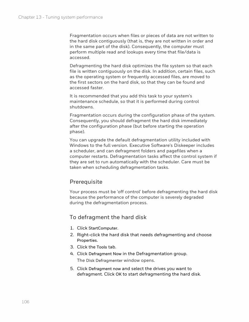
Fragmentation occurs when files or pieces of data are not written to the hard disk contiguously (that is, they are not written in order and in the same part of the disk). Consequently, the computer must perform multiple read and lookups every time that file/data is accessed.
Defragmenting the hard disk optimizes the file system so that each file is written contiguously on the disk. In addition, certain files, such as the operating system or frequently accessed files, are moved to the first sectors on the hard disk, so that they can be found and accessed faster.
It is recommended that you add this task to your system's maintenance schedule, so that it is performed during control shutdowns.
Fragmentation occurs during the configuration phase of the system. Consequently, you should defragment the hard disk immediately after the configuration phase (but before starting the operation phase).
You can upgrade the default defragmentation utility included with Windows to the full version. Executive Software's Diskeeper includes a scheduler, and can defragment folders and pagefiles when a computer restarts. Defragmentation tasks affect the control system if they are set to run automatically with the scheduler. Care must be taken when scheduling defragmentation tasks.
Prerequisite
Your process must be 'off control' before defragmenting the hard disk because the performance of the computer is severely degraded during the defragmentation process.
To defragment the hard disk
1. Click StartComputer. 2. Right-click the hard disk that needs defragmenting and choose
Properties. 3. Click the Tools tab. 4. Click Defragment Now in the Defragmentation group.
The Disk Defragmenter window opens.
5. Click Defragment now and select the drives you want to defragment. Click OK to start defragmenting the hard disk.
106
Chapter 13 - Tuning system performance

107
Depending on the level of fragmentation and usage, the task may take some time to complete.
Optimizing the server's memory usageComputers have two types of memory: physical and virtual. Multi-tasking operating systems, such as Windows, can move data from the RAM (physical memory) and swap it to a file on the hard disk (virtual memory). This technique frees up the RAM for other processes. If a process requires data which has been swapped to a file, the data is first swapped back from the file to RAM so that the process can continue. This technique is called paging, and the file is called the pagefile.
Viewing memory usageIn the Windows Task Manager dialog box you can view memory usage.
To view memory usage
1. In the Windows Task Manager dialog box, click the Performance tab.The Commit Charge (K) group displays the total memory available in physical and virtual memory combined (the Limit value).The Physical Memory (K) group displays the amount of physical memory available for use.
Increase memory to reduce pagingSome paging is normal. However, excessive paging affects computer performance during the swapping and allocation phases.
If a computer pages frequently during normal operation, you can significantly improve its performance by adding more physical RAM. However, if you do add more RAM, you must make the appropriate adjustments to the virtual memory configuration.
Chapter 13 - Tuning system performance
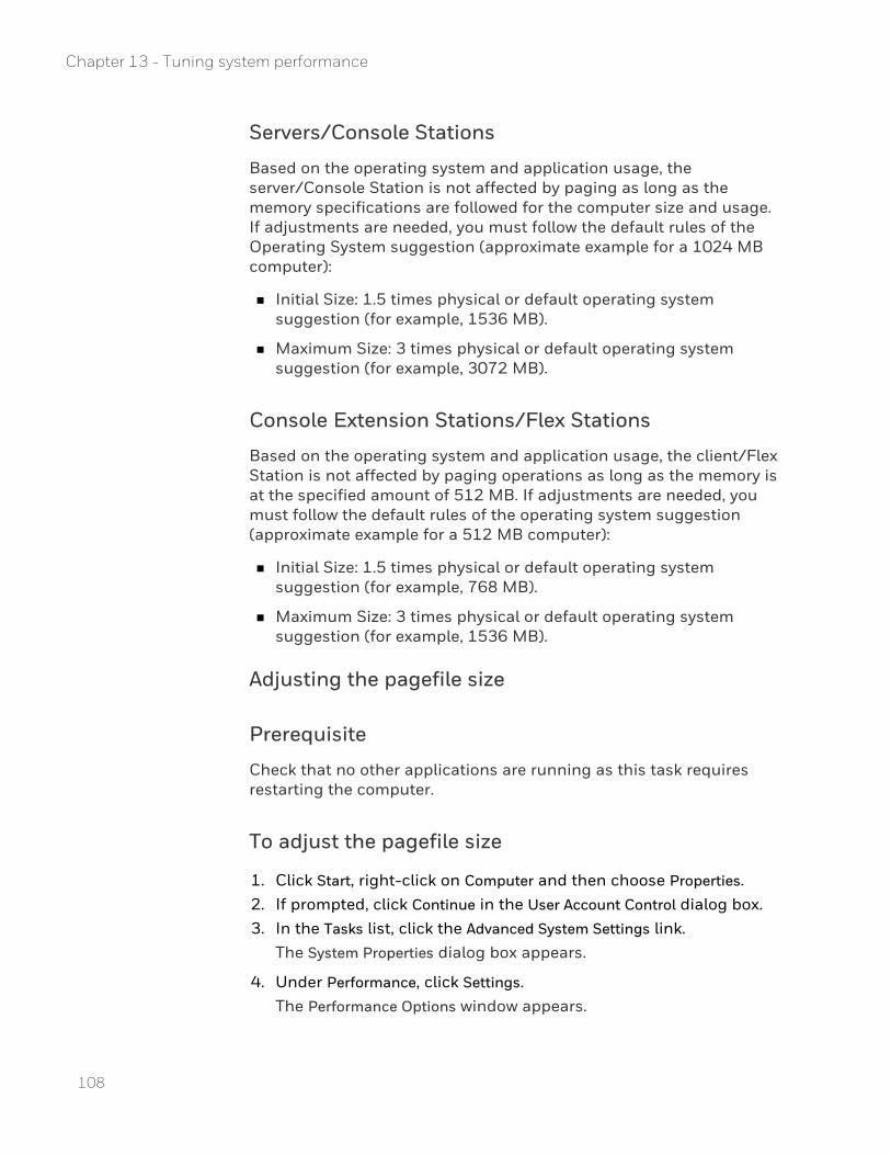
Servers/Console Stations
Based on the operating system and application usage, the server/Console Station is not affected by paging as long as the memory specifications are followed for the computer size and usage. If adjustments are needed, you must follow the default rules of the Operating System suggestion (approximate example for a 1024 MB computer):
n Initial Size: 1.5 times physical or default operating system suggestion (for example, 1536 MB).
n Maximum Size: 3 times physical or default operating system suggestion (for example, 3072 MB).
Console Extension Stations/Flex Stations
Based on the operating system and application usage, the client/Flex Station is not affected by paging operations as long as the memory is at the specified amount of 512 MB. If adjustments are needed, you must follow the default rules of the operating system suggestion (approximate example for a 512 MB computer):
n Initial Size: 1.5 times physical or default operating system suggestion (for example, 768 MB).
n Maximum Size: 3 times physical or default operating system suggestion (for example, 1536 MB).
Adjusting the pagefile size
Prerequisite
Check that no other applications are running as this task requires restarting the computer.
To adjust the pagefile size
1. Click Start, right-click on Computer and then choose Properties. 2. If prompted, click Continue in the User Account Control dialog box. 3. In the Tasks list, click the Advanced System Settings link.
The System Properties dialog box appears.
4. Under Performance, click Settings.The Performance Options window appears.
108
Chapter 13 - Tuning system performance
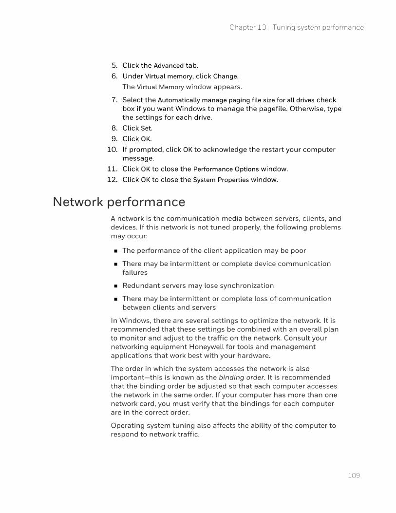
109
5. Click the Advanced tab. 6. Under Virtual memory, click Change.
The Virtual Memory window appears.
7. Select the Automatically manage paging file size for all drives check box if you want Windows to manage the pagefile. Otherwise, type the settings for each drive.
8. Click Set. 9. Click OK.
10. If prompted, click OK to acknowledge the restart your computer message.
11. Click OK to close the Performance Options window. 12. Click OK to close the System Properties window.
Network performanceA network is the communication media between servers, clients, and devices. If this network is not tuned properly, the following problems may occur:
n The performance of the client application may be poor
n There may be intermittent or complete device communication failures
n Redundant servers may lose synchronization
n There may be intermittent or complete loss of communication between clients and servers
In Windows, there are several settings to optimize the network. It is recommended that these settings be combined with an overall plan to monitor and adjust to the traffic on the network. Consult your networking equipment Honeywell for tools and management applications that work best with your hardware.
The order in which the system accesses the network is also important—this is known as the binding order. It is recommended that the binding order be adjusted so that each computer accesses the network in the same order. If your computer has more than one network card, you must verify that the bindings for each computer are in the correct order.
Operating system tuning also affects the ability of the computer to respond to network traffic.
Chapter 13 - Tuning system performance
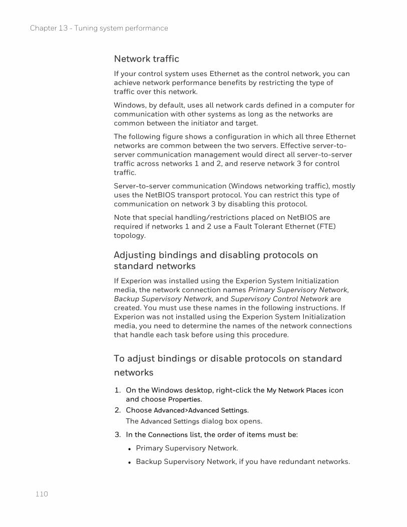
Network trafficIf your control system uses Ethernet as the control network, you can achieve network performance benefits by restricting the type of traffic over this network.
Windows, by default, uses all network cards defined in a computer for communication with other systems as long as the networks are common between the initiator and target.
The following figure shows a configuration in which all three Ethernet networks are common between the two servers. Effective server-to-server communication management would direct all server-to-server traffic across networks 1 and 2, and reserve network 3 for control traffic.
Server-to-server communication (Windows networking traffic), mostly uses the NetBIOS transport protocol. You can restrict this type of communication on network 3 by disabling this protocol.
Note that special handling/restrictions placed on NetBIOS are required if networks 1 and 2 use a Fault Tolerant Ethernet (FTE) topology.
Adjusting bindings and disabling protocols on standard networksIf Experion was installed using the Experion System Initialization media, the network connection names Primary Supervisory Network, Backup Supervisory Network, and Supervisory Control Network are created. You must use these names in the following instructions. If Experion was not installed using the Experion System Initialization media, you need to determine the names of the network connections that handle each task before using this procedure.
To adjust bindings or disable protocols on standard networks
1. On the Windows desktop, right-click the My Network Places icon and choose Properties.
2. Choose Advanced>Advanced Settings.The Advanced Settings dialog box opens.
3. In the Connections list, the order of items must be:
l Primary Supervisory Network.
l Backup Supervisory Network, if you have redundant networks.
110
Chapter 13 - Tuning system performance
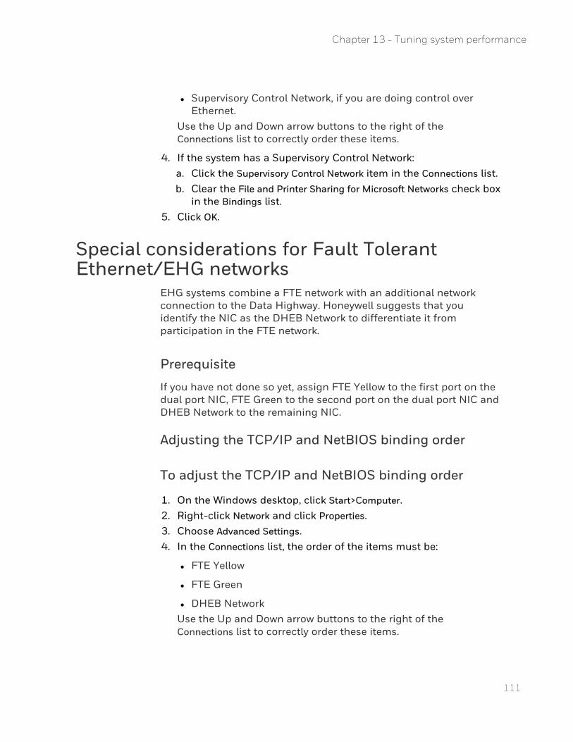
111
l Supervisory Control Network, if you are doing control over Ethernet.
Use the Up and Down arrow buttons to the right of the Connections list to correctly order these items.
4. If the system has a Supervisory Control Network: a. Click the Supervisory Control Network item in the Connections list. b. Clear the File and Printer Sharing for Microsoft Networks check box
in the Bindings list. 5. Click OK.
Special considerations for Fault Tolerant Ethernet/EHG networks
EHG systems combine a FTE network with an additional network connection to the Data Highway. Honeywell suggests that you identify the NIC as the DHEB Network to differentiate it from participation in the FTE network.
Prerequisite
If you have not done so yet, assign FTE Yellow to the first port on the dual port NIC, FTE Green to the second port on the dual port NIC and DHEB Network to the remaining NIC.
Adjusting the TCP/IP and NetBIOS binding order
To adjust the TCP/IP and NetBIOS binding order
1. On the Windows desktop, click Start>Computer. 2. Right-click Network and click Properties. 3. Choose Advanced Settings. 4. In the Connections list, the order of the items must be:
l FTE Yellow
l FTE Green
l DHEB NetworkUse the Up and Down arrow buttons to the right of the Connections list to correctly order these items.
Chapter 13 - Tuning system performance
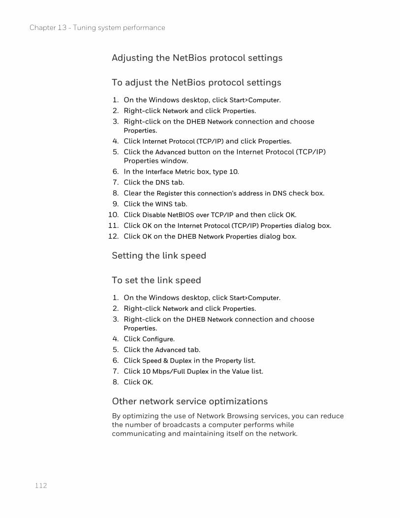
Adjusting the NetBios protocol settings
To adjust the NetBios protocol settings
1. On the Windows desktop, click Start>Computer. 2. Right-click Network and click Properties. 3. Right-click on the DHEB Network connection and choose
Properties. 4. Click Internet Protocol (TCP/IP) and click Properties. 5. Click the Advanced button on the Internet Protocol (TCP/IP)
Properties window. 6. In the Interface Metric box, type 10.
7. Click the DNS tab. 8. Clear the Register this connection's address in DNS check box. 9. Click the WINS tab.
10. Click Disable NetBIOS over TCP/IP and then click OK. 11. Click OK on the Internet Protocol (TCP/IP) Properties dialog box. 12. Click OK on the DHEB Network Properties dialog box.
Setting the link speed
To set the link speed
1. On the Windows desktop, click Start>Computer. 2. Right-click Network and click Properties. 3. Right-click on the DHEB Network connection and choose
Properties. 4. Click Configure. 5. Click the Advanced tab. 6. Click Speed & Duplex in the Property list. 7. Click 10 Mbps/Full Duplex in the Value list. 8. Click OK.
Other network service optimizationsBy optimizing the use of Network Browsing services, you can reduce the number of broadcasts a computer performs while communicating and maintaining itself on the network.
112
Chapter 13 - Tuning system performance
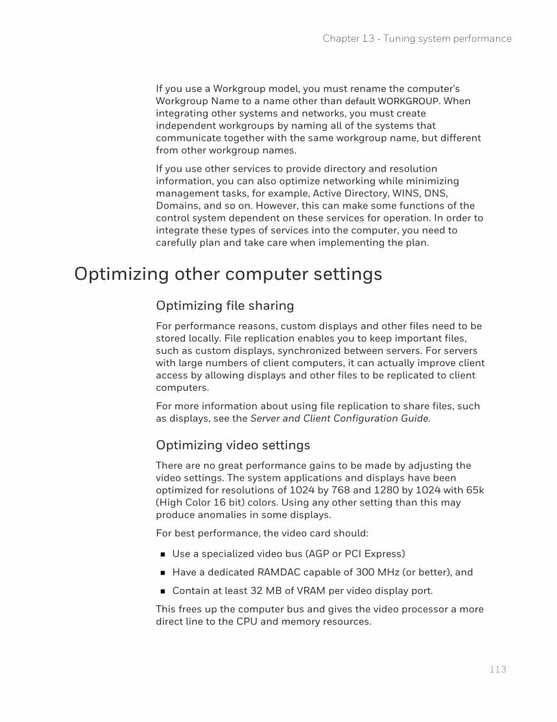
113
If you use a Workgroup model, you must rename the computer's Workgroup Name to a name other than default WORKGROUP. When integrating other systems and networks, you must create independent workgroups by naming all of the systems that communicate together with the same workgroup name, but different from other workgroup names.
If you use other services to provide directory and resolution information, you can also optimize networking while minimizing management tasks, for example, Active Directory, WINS, DNS, Domains, and so on. However, this can make some functions of the control system dependent on these services for operation. In order to integrate these types of services into the computer, you need to carefully plan and take care when implementing the plan.
Optimizing other computer settings
Optimizing file sharingFor performance reasons, custom displays and other files need to be stored locally. File replication enables you to keep important files, such as custom displays, synchronized between servers. For servers with large numbers of client computers, it can actually improve client access by allowing displays and other files to be replicated to client computers.
For more information about using file replication to share files, such as displays, see the Server and Client Configuration Guide.
Optimizing video settingsThere are no great performance gains to be made by adjusting the video settings. The system applications and displays have been optimized for resolutions of 1024 by 768 and 1280 by 1024 with 65k (High Color 16 bit) colors. Using any other setting than this may produce anomalies in some displays.
For best performance, the video card should:
n Use a specialized video bus (AGP or PCI Express)
n Have a dedicated RAMDAC capable of 300 MHz (or better), and
n Contain at least 32 MB of VRAM per video display port.
This frees up the computer bus and gives the video processor a more direct line to the CPU and memory resources.
Chapter 13 - Tuning system performance

Optimizing system usageThe system usage itself will have an impact on the performance of the system. Most memory and CPU recommendations are based on 'average' use of the system, which means that your system may require servers with, for example, more memory, higher CPU speed or larger disks.
These types of adjustments can only occur over time as you gain experience with your system. The following will affect the performance of your system:
n Number of Stations, and:
l The display update rate
l Shared versus local displays
l Chart visualization
l The number of parameters viewed (across all Stations) and their frequency of change
n Frequency of report generation
n Frequency of performed maintenance, for example, defragmentation level of the disk
n If you have a DSA system, the number of servers and the number of shared parameters
n The amount of history being collected
n The frequency at which events are archived and the duration for which events are kept online
n Server synchronization with file backup
n Size of the system, including the size of the Engineering Repository database for Process systems
As your system is adjusted over time and customized to your control environment, you should regularly evaluate how your systems are performing and make the appropriate adjustments.
114
Chapter 13 - Tuning system performance
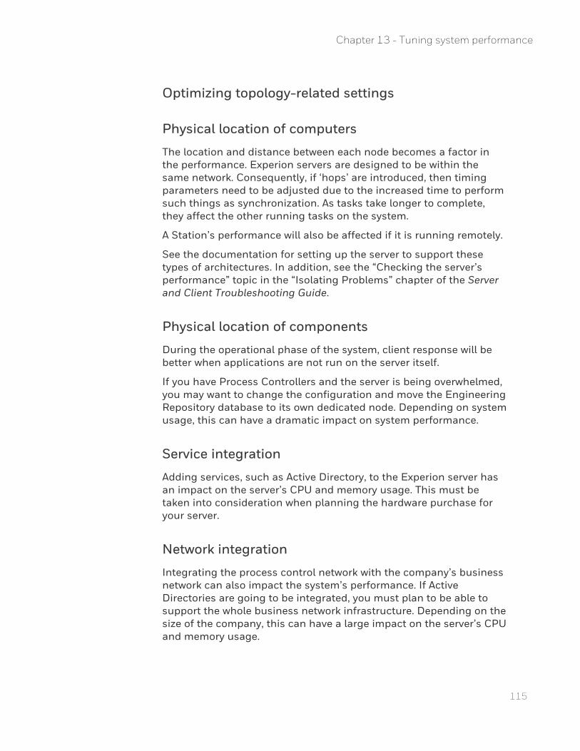
115
Optimizing topology-related settings
Physical location of computers
The location and distance between each node becomes a factor in the performance. Experion servers are designed to be within the same network. Consequently, if ‘hops’ are introduced, then timing parameters need to be adjusted due to the increased time to perform such things as synchronization. As tasks take longer to complete, they affect the other running tasks on the system.
A Station’s performance will also be affected if it is running remotely.
See the documentation for setting up the server to support these types of architectures. In addition, see the “Checking the server’s performance” topic in the “Isolating Problems” chapter of the Server and Client Troubleshooting Guide.
Physical location of components
During the operational phase of the system, client response will be better when applications are not run on the server itself.
If you have Process Controllers and the server is being overwhelmed, you may want to change the configuration and move the Engineering Repository database to its own dedicated node. Depending on system usage, this can have a dramatic impact on system performance.
Service integration
Adding services, such as Active Directory, to the Experion server has an impact on the server’s CPU and memory usage. This must be taken into consideration when planning the hardware purchase for your server.
Network integration
Integrating the process control network with the company’s business network can also impact the system’s performance. If Active Directories are going to be integrated, you must plan to be able to support the whole business network infrastructure. Depending on the size of the company, this can have a large impact on the server’s CPU and memory usage.
Chapter 13 - Tuning system performance
Optimizing the scanning loadThis section is only applicable if you have controllers other than Process Controllers.
Controllers with badly configured scanning can place a significant load on the system and result in data not being accurately represented in the server database.
It is also important to remember that making even seemingly minor changes to a controller's configuration—such as adding a few new points—can have a significant impact on a system and can result in unstable performance.
Guidelines for scan optimization
n Use unsolicited messaging if the controller supports this feature and values change infrequently.
n Use periodic scanning if values change frequently.
n Choose a scanning period appropriate to the values being scanned. For example, you do not need to scan a temperature every 5 seconds if it changes only slightly over an hour. See the section below titled "Choosing an appropriate periodic scanning period" for more information.
n Minimize the number of scan packets as follows:
l Specify the minimum number of scan periods for a given controller because the server requires a separate scan for each scan period. For example, you may only need two scan periods for a particular controller: a short one for a few critical values, and a long one for all other values.
l For each scan period you use, specify the longest period that is acceptable to your needs.
l Arrange parameter value addresses so that they occupy contiguous addresses in the controller's memory, as shown in the following figure. If parameters occupy contiguous addresses, the server can access many parameters in a single scan—the exact number is controller-specific.
116
Chapter 13 - Tuning system performance

117
Choosing an appropriate periodic scanning period
Periodic scanning involves reading parameter values at specified time intervals. This means that you need to select an appropriate scan period, ranging from seconds to minutes, for each input/output parameter. For example, if you assign a scan period of 15 seconds to the PV, the server scans the value in the controller every 15 seconds.
When choosing a scan period, consider the following factors:
n The rate of change of the value. If a value only changes once an hour, it is inefficient to scan that value every five seconds.
n The period at which you need to collect history for the point (in the case of the PV parameter). A point requiring one minute snapshots needs a scan period less than 60 seconds.
n How quickly field changes need to appear in Station displays. Dynamic values on a display are updated from the database at the configured update rate of the Station.
n The number of values that can be scanned from a controller at a particular scan period. For example, it is unlikely that 2,000 analog values could be scanned every second from a controller connected to server via a serial line operating at 1200 baud.
Chapter 13 - Tuning system performance
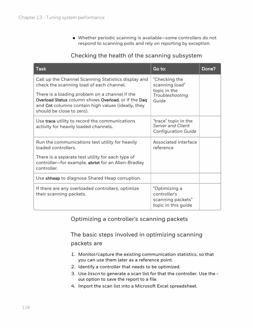
n Whether periodic scanning is available—some controllers do not respond to scanning polls and rely on reporting by exception.
Checking the health of the scanning subsystem
Task Go to: Done?
Call up the Channel Scanning Statistics display and check the scanning load of each channel.
There is a loading problem on a channel if the Overload Status column shows Overload, or if the Daq and Cnt columns contain high values (ideally, they should be close to zero).
"Checking the scanning load" topic in the Troubleshooting Guide
Use trace utility to record the communications activity for heavily loaded channels.
"trace" topic in the Server and Client Configuration Guide
Run the communications test utility for heavily loaded controllers.
There is a separate test utility for each type of controller—for example, abrtst for an Allen-Bradley controller.
Associated interface reference
Use shheap to diagnose Shared Heap corruption.
If there are any overloaded controllers, optimize their scanning packets.
"Optimizing a controller's scanning packets" topic in this guide
Optimizing a controller's scanning packets
The basic steps involved in optimizing scanning packets are
1. Monitor/capture the existing communication statistics, so that you can use them later as a reference point.
2. Identify a controller that needs to be optimized. 3. Use lisscn to generate a scan list for that the controller. Use the -
out option to save the report to a file. 4. Import the scan list into a Microsoft Excel spreadsheet.
118
Chapter 13 - Tuning system performance
119
5. Manipulate the spreadsheet and analyze the current scanning efficiency.
6. Change the scanning settings in accordance with your analysis. 7. Monitor/capture the new communication statistics, and compare
them with the original statistics. 8. Use lisscn to generate a new scan list and check that your
changes have had the desired effect.
Importing the scan list into a spreadsheet
To import the scan list into a spreadsheet
1. Open a new spreadsheet. 2. Choose Data>Import External Data>Import Data. 3. Select the scan list file and click Open. 4. In the Text Import Wizard, select Fixed width and click Next. 5. Adjust the lines so that the data is imported into the correct
columns, such as Index, Scan type and Point/Parameter. 6. Click Next and then click Finish. 7. Select Existing worksheet and click OK.
Manipulating and analyzing the spreadsheetAfter importing the scan list into Excel, you manipulate the list so that you can analyze the current scanning efficiency.
To manipulate the spreadsheet
1. Add a column on the right, label it 'Period' and fill in the scan period for each row.
2. Sort the spreadsheet by index. 3. Clean up the spreadsheet by removing unnecessary rows and, for
example, removing 'for' after the addresses. 4. Sort the spreadsheet by Address.
Next steps
You can now see how efficient your current scanning strategy is, and where you can make improvements.
Chapter 13 - Tuning system performance
Ideally contiguous addresses should have the same scanning period—unlike the above figure, where almost every subsequent address has a different period.
Having analyzed the problem, you can make appropriate adjustments to the scanning periods. In the above figure, for example, if it is not possible to slow all points down to 5 seconds or to speed them up to 1 second, you may find it acceptable to change the scan rate of all points to 2 seconds.
Monitoring the system
Assessing the need for hardware upgradesMost monitoring of the system should be done during the operational phase of the system.
The Windows Event Viewer
The Windows Event Manager (System and Application Logs) should be checked immediately after installation and major configuration changes. Errors in configuration and problems with components in the system are reported in these logs. If you locate any, you should contact your Honeywell Technical Assistance Center (TAC) for assistance in getting them resolved.
After initial configuration, you should periodically check for any new errors in the log. This should be part of your normal maintenance routines.
Using Dell OpenManageIf the computer was installed using the Experion Initialization Media, the Dell OpenManage tools are pre-installed and configured.
ATTENTION: Dell supplies OpenManage only for the current MZ-PCSV20, -30, and ‐50 server models and the previous MZ-NTPC51, -71 and -81 server models.
The Dell OpenManage tools monitor the performance and operation of the internal hardware components that make up the system. If any type of hardware event occurs, the system will notify the user and, if necessary, perform critical actions to prevent more major problems from occurring.
120
Chapter 13 - Tuning system performance
121
These tools are also available on computers where Experion was not installed using the Experion System Initialization media, but you need to download, install, and configure the software.
There are two types of Dell OpenManage client software:
n Dell OpenManage Server Administrator (OMSA) for server operating systems.
n Dell OpenManage Client Interface (OMCI) for client operating systems.
OMSA provides a view application to look at hardware events and internal sensor readings. OMCI requires a central application (Dell's IT Administrator) to view the hardware events and internal sensor readings. (This does not stop the software from reporting events local on the system.)
Dell's IT Administrator application must not be installed on any Experion node. It must be on a dedicated computer if used with an Experion system. Dell IT Administrator application is not required, as both client applications are SMTP and CIM compliant. They can interoperate with any central system monitoring utilities such as HP OpenView, Tivoli, or other systems that support these standards.
Monitoring performanceA range of Windows Performance Monitor counters are collected to allow for analysis by the Honeywell Technical Assistance Center if required. You may want to actively monitor some of these counters for signs of system performance issues.
NOTE: The OPC counter values reported by the Performance Monitor are related to OPC Classic transactions only and not to OPC UA.
This procedure is also applicable to Console Stations.
If the computer was installed using the Experion Initialization Media, a performance monitoring tool is configured and installed.
If your computer was not ordered with the Experion installation using the Experion System Initialization media, you first need to configure the Performance Monitor as described below.
Chapter 13 - Tuning system performance
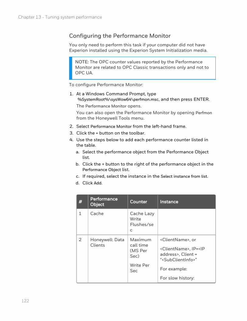
Configuring the Performance MonitorYou only need to perform this task if your computer did not have Experion installed using the Experion System Initialization media.
NOTE: The OPC counter values reported by the Performance Monitor are related to OPC Classic transactions only and not to OPC UA.
To configure Performance Monitor:
1. At a Windows Command Prompt, type %SystemRoot%\sysWow64\perfmon.msc, and then press ENTER.The Performance Monitor opens.You can also open the Performance Monitor by opening Perfmon from the Honeywell Tools menu.
2. Select Performance Monitor from the left-hand frame. 3. Click the + button on the toolbar. 4. Use the steps below to add each performance counter listed in
the table. a. Select the performance object from the Performance Object
list. b. Click the + button to the right of the performance object in the
Performance Object list. c. If required, select the instance in the Select instance from list. d. Click Add.
# Performance Object Counter Instance
1 Cache Cache Lazy Write Flushes/sec
2 Honeywell: Data Clients
Maximum call time (MS Per Sec)
Write Per Sec
<ClientName>, or
<ClientName>, IP=<IP address>, Client = “<SubClientInfo>”
For example:
For slow history:
122
Chapter 13 - Tuning system performance
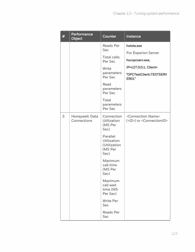
123
# Performance Object Counter Instance
Reads Per Sec
Total calls Per Sec
Write parameters Per Sec
Read parameters Per Sec
Total parameters Per Sec
hstslw.exe
For Experion Server
hscopcserv.exe,
IP=127.0.0.1, Client=
"OPCTestClient::TESTSERVER01"
3 Honeywell: Data Connections
Connection Utilization (MS Per Sec)
Parallel Utilization (Utilization (MS Per Sec)
Maximum call time (MS Per Sec)
Maximum call wait time (MS Per Sec)
Write Per Sec
Reads Per Sec
<Connection Name> (<ID>) or <ConnectionID>
Chapter 13 - Tuning system performance
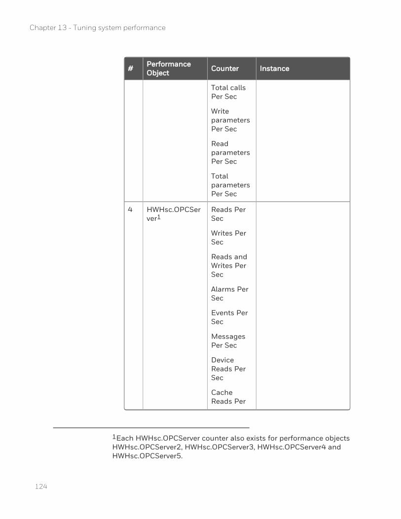
# Performance Object Counter Instance
Total calls Per Sec
Write parameters Per Sec
Read parameters Per Sec
Total parameters Per Sec
4 HWHsc.OPCServer1
Reads Per Sec
Writes Per Sec
Reads and Writes Per Sec
Alarms Per Sec
Events Per Sec
Messages Per Sec
Device Reads Per Sec
Cache Reads Per
1Each HWHsc.OPCServer counter also exists for performance objects HWHsc.OPCServer2, HWHsc.OPCServer3, HWHsc.OPCServer4 and HWHsc.OPCServer5.
124
Chapter 13 - Tuning system performance
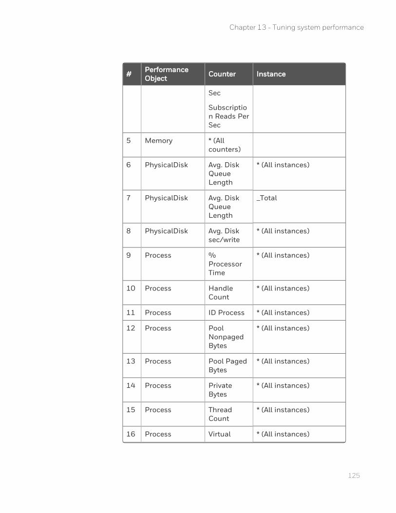
125
# Performance Object Counter Instance
Sec
Subscription Reads Per Sec
5 Memory * (All counters)
6 PhysicalDisk Avg. Disk Queue Length
* (All instances)
7 PhysicalDisk Avg. Disk Queue Length
_Total
8 PhysicalDisk Avg. Disk sec/write
* (All instances)
9 Process % Processor Time
* (All instances)
10 Process Handle Count
* (All instances)
11 Process ID Process * (All instances)
12 Process Pool Nonpaged Bytes
* (All instances)
13 Process Pool Paged Bytes
* (All instances)
14 Process Private Bytes
* (All instances)
15 Process Thread Count
* (All instances)
16 Process Virtual * (All instances)
Chapter 13 - Tuning system performance
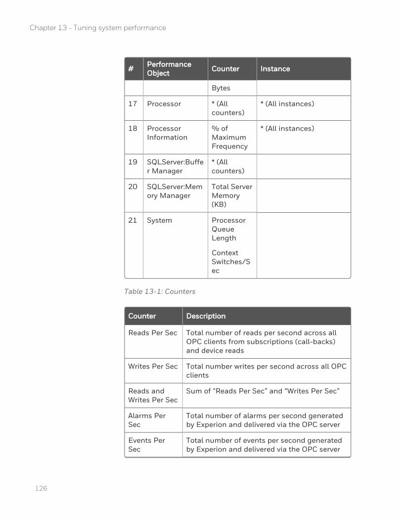
# Performance Object Counter Instance
Bytes
17 Processor * (All counters)
* (All instances)
18 Processor Information
% of Maximum Frequency
* (All instances)
19 SQLServer:Buffer Manager
* (All counters)
20 SQLServer:Memory Manager
Total Server Memory (KB)
21 System Processor Queue Length
Context Switches/Sec
Table 13-1: Counters
Counter Description
Reads Per Sec Total number of reads per second across all OPC clients from subscriptions (call-backs) and device reads
Writes Per Sec Total number writes per second across all OPC clients
Reads and Writes Per Sec
Sum of “Reads Per Sec” and “Writes Per Sec”
Alarms Per Sec
Total number of alarms per second generated by Experion and delivered via the OPC server
Events Per Sec
Total number of events per second generated by Experion and delivered via the OPC server
126
Chapter 13 - Tuning system performance
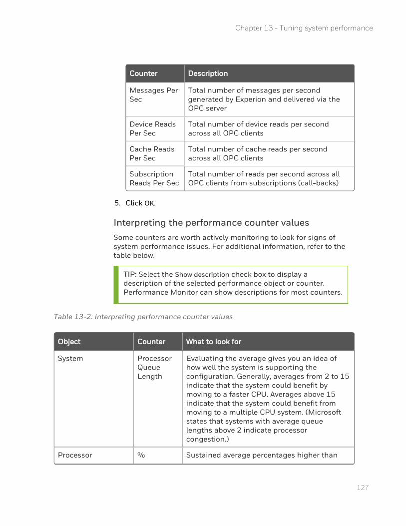
127
Counter Description
Messages Per Sec
Total number of messages per second generated by Experion and delivered via the OPC server
Device Reads Per Sec
Total number of device reads per second across all OPC clients
Cache Reads Per Sec
Total number of cache reads per second across all OPC clients
Subscription Reads Per Sec
Total number of reads per second across all OPC clients from subscriptions (call-backs)
5. Click OK.
Interpreting the performance counter valuesSome counters are worth actively monitoring to look for signs of system performance issues. For additional information, refer to the table below.
TIP: Select the Show description check box to display a description of the selected performance object or counter. Performance Monitor can show descriptions for most counters.
Table 13-2: Interpreting performance counter values
Object Counter What to look for
System Processor Queue Length
Evaluating the average gives you an idea of how well the system is supporting the configuration. Generally, averages from 2 to 15 indicate that the system could benefit by moving to a faster CPU. Averages above 15 indicate that the system could benefit from moving to a multiple CPU system. (Microsoft states that systems with average queue lengths above 2 indicate processor congestion.)
Processor % Sustained average percentages higher than
Chapter 13 - Tuning system performance

Object Counter What to look for
Processor Time
80% may indicate that there is a problem with your system.
Note that the “_Total” instance shows the total of all processors. For example, if you have 8 logical processors (such as on a single CPU with 4 cores and hyperthreading enabled), this could reach 800%.
Memory Available MBytes
Sustained values representing less than 5% of the physical memory on your system may indicate that there is a problem with your system.
PhysicalDisk Avg. Disk Queue Length
Sustained values above 2 may indicate that there is a problem with your system.
HWHsc.OPCServer All counters Compare values with the limits documented in the Experion Specification.
Monitoring System Health
About System Health MonitoringThe System Health Monitor ties together local node health events with the Experion PKS System Alarm Summary. Monitoring examples include:
n Computer specific resources
n Node specific hardware
The System Health Monitor is a local node service that monitors the computer, compares it against a System Health Rules File and logs events when a fault has occurred. In order to send the event to the Experion PKS System Alarm display, the System Event Server uses a corresponding event filter file that handles the events raised from the System Health Monitor. Users can modify the filter file or rules files to include additional fault rules.
128
Chapter 13 - Tuning system performance
129
System Health Monitoring considerationsThe System Health Monitoring service is installed during an Experion install with the system management runtime package. You do not need to perform any service installation as the default installation enables system health monitoring. The System Health Monitoring service runs locally and can monitor the local node without the system definition residing in the Enterprise Model Database (EMDB).
You can configure the System Event Server to access a System Health Monitoring event filter file that allows System Health Monitoring faults to appear as system events in the Experion System Alarm summary. You can also view the logged System Health Monitored events from the nodes' Windows event log, whether or not the System Event Server is available to support System Health Monitoring.
Modifying System Health rules filesIn most cases you should not have to modify the rules files because the default rules files should meet most of your needs. You will need some knowledge of Windows system administration and/or OPC concepts if you modify a rule (fault model).
You modify the default System Health Rules files using the System Health Monitor Expression Builder in the Diagnostic Studio. The rules are stored to System Health Rules files that are read by the local System Health Monitoring service.
ATTENTION: The System Health Monitor Expression Builder tool supports updating the rules for the System Health Monitoring service. Honeywell recommends that the rules only be updated using System Health Monitor Expression Builder because the tool provides rule validation.
For more information about the System Health Monitor Expression Builder and modifying System Health rules files, see the Diagnostic Studio User's Guide.
Chapter 13 - Tuning system performance

130
Chapter 13 - Tuning system performance
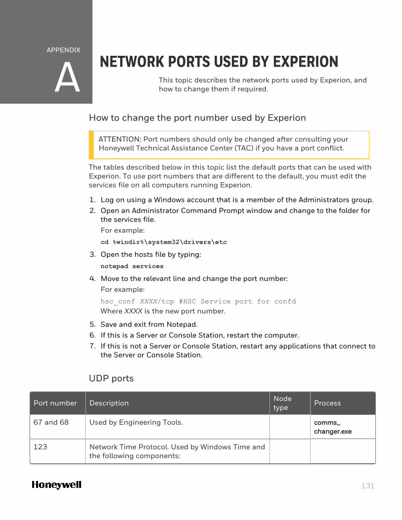
APPENDIX
AHow to change the port number used by Experion
ATTENTION: Port numbers should only be changed after consulting your Honeywell Technical Assistance Center (TAC) if you have a port conflict.
The tables described below in this topic list the default ports that can be used with Experion. To use port numbers that are different to the default, you must edit the services file on all computers running Experion.
1. Log on using a Windows account that is a member of the Administrators group. 2. Open an Administrator Command Prompt window and change to the folder for
the services file.For example:
cd %windir%\system32\drivers\etc
3. Open the hosts file by typing:
notepad services
4. Move to the relevant line and change the port number:For example:
hsc_conf XXXX/tcp #HSC Service port for confdWhere XXXX is the new port number.
5. Save and exit from Notepad. 6. If this is a Server or Console Station, restart the computer. 7. If this is not a Server or Console Station, restart any applications that connect to
the Server or Console Station.
UDP ports
Port number Description Node type Process
67 and 68 Used by Engineering Tools. comms_changer.exe
123 Network Time Protocol. Used by Windows Time and the following components:
NETWORK PORTS USED BY EXPERIONThis topic describes the network ports used by Experion, and how to change them if required.
131
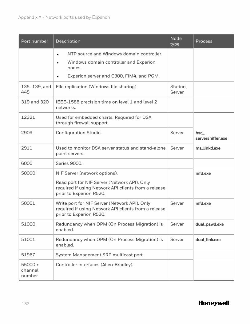
Appendix A - Network ports used by Experion
Port number Description Node type Process
l NTP source and Windows domain controller.
l Windows domain controller and Experion nodes.
l Experion server and C300, FIM4, and PGM.
135–139, and 445
File replication (Windows file sharing). Station, Server
319 and 320 IEEE-1588 precision time on level 1 and level 2 networks.
12321 Used for embedded charts. Required for DSA through firewall support.
2909 Configuration Studio. Server hsc_serversniffer.exe
2911 Used to monitor DSA server status and stand-alone point servers.
Server ms_linkd.exe
6000 Series 9000.
50000 NIF Server (network options).
Read port for NIF Server (Network API). Only required if using Network API clients from a release prior to Experion R520.
nifd.exe
50001 Write port for NIF Server (Network API). Only required if using Network API clients from a release prior to Experion R520.
Server nifd.exe
51000 Redundancy when OPM (On Process Migration) is enabled.
Server dual_pswd.exe
51001 Redundancy when OPM (On Process Migration) is enabled.
Server dual_link.exe
51967 System Management SRP multicast port.
55000 + channel number
Controller interfaces (Allen‐Bradley).
132
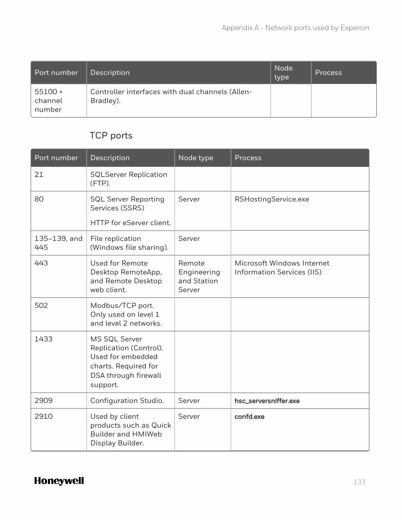
Appendix A - Network ports used by Experion
Port number Description Node type Process
55100 + channel number
Controller interfaces with dual channels (Allen‐Bradley).
TCP ports
Port number Description Node type Process
21 SQLServer Replication (FTP).
80 SQL Server Reporting Services (SSRS)
HTTP for eServer client.
Server RSHostingService.exe
135–139, and 445
File replication (Windows file sharing).
Server
443 Used for Remote Desktop RemoteApp, and Remote Desktop web client.
Remote Engineering and Station Server
Microsoft Windows Internet Information Services (IIS)
502 Modbus/TCP port. Only used on level 1 and level 2 networks.
1433 MS SQL Server Replication (Control). Used for embedded charts. Required for DSA through firewall support.
2909 Configuration Studio. Server hsc_serversniffer.exe
2910 Used by client products such as Quick Builder and HMIWeb Display Builder.
Server confd.exe
133
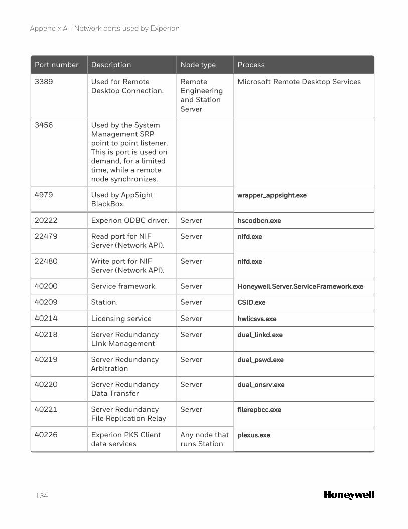
Appendix A - Network ports used by Experion
Port number Description Node type Process
3389 Used for Remote Desktop Connection.
Remote Engineering and Station Server
Microsoft Remote Desktop Services
3456 Used by the System Management SRP point to point listener. This is port is used on demand, for a limited time, while a remote node synchronizes.
4979 Used by AppSight BlackBox.
wrapper_appsight.exe
20222 Experion ODBC driver. Server hscodbcn.exe
22479 Read port for NIF Server (Network API).
Server nifd.exe
22480 Write port for NIF Server (Network API).
Server nifd.exe
40200 Service framework. Server Honeywell.Server.ServiceFramework.exe
40209 Station. Server CSID.exe
40214 Licensing service Server hwlicsvs.exe
40218 Server Redundancy Link Management
Server dual_linkd.exe
40219 Server Redundancy Arbitration
Server dual_pswd.exe
40220 Server Redundancy Data Transfer
Server dual_onsrv.exe
40221 Server Redundancy File Replication Relay
Server filerepbcc.exe
40226 Experion PKS Client data services
Any node that runs Station
plexus.exe
134
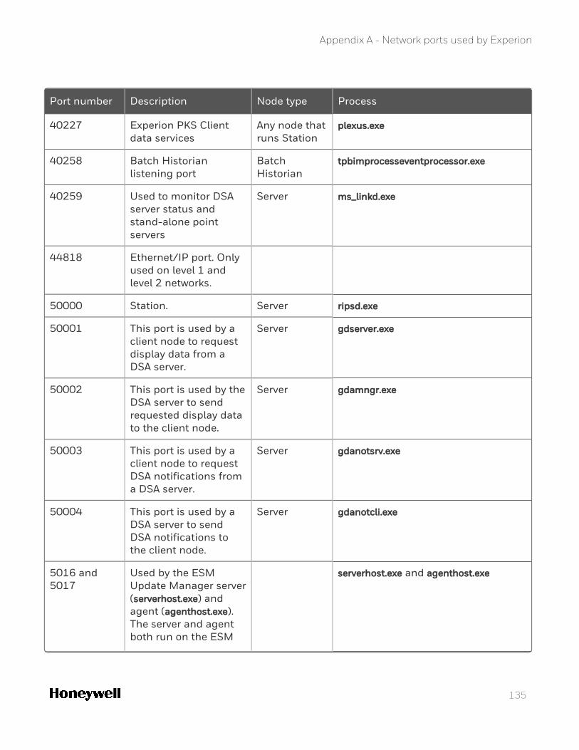
Appendix A - Network ports used by Experion
Port number Description Node type Process
40227 Experion PKS Client data services
Any node that runs Station
plexus.exe
40258 Batch Historian listening port
Batch Historian
tpbimprocesseventprocessor.exe
40259 Used to monitor DSA server status and stand-alone point servers
Server ms_linkd.exe
44818 Ethernet/IP port. Only used on level 1 and level 2 networks.
50000 Station. Server ripsd.exe
50001 This port is used by a client node to request display data from a DSA server.
Server gdserver.exe
50002 This port is used by the DSA server to send requested display data to the client node.
Server gdamngr.exe
50003 This port is used by a client node to request DSA notifications from a DSA server.
Server gdanotsrv.exe
50004 This port is used by a DSA server to send DSA notifications to the client node.
Server gdanotcli.exe
5016 and 5017
Used by the ESM Update Manager server (serverhost.exe) and agent (agenthost.exe). The server and agent both run on the ESM
serverhost.exe and agenthost.exe
135
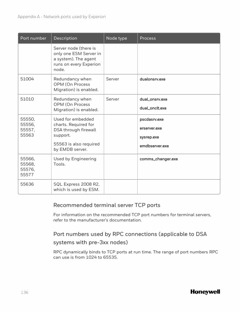
Appendix A - Network ports used by Experion
Port number Description Node type Process
Server node (there is only one ESM Server in a system). The agent runs on every Experion node.
51004 Redundancy when OPM (On Process Migration) is enabled.
Server dualonsrv.exe
51010 Redundancy when OPM (On Process Migration) is enabled.
Server dual_onsrv.exe
dual_onclt.exe
55550, 55556, 55557, 55563
Used for embedded charts. Required for DSA through firewall support.
55563 is also required by EMDB server.
pscdasrv.exe
erserver.exe
sysrep.exe
emdbserver.exe
55566, 55568, 55576, 55577
Used by Engineering Tools.
comms_changer.exe
55636 SQL Express 2008 R2, which is used by ESM.
Recommended terminal server TCP ports
For information on the recommended TCP port numbers for terminal servers, refer to the manufacturer's documentation.
Port numbers used by RPC connections (applicable to DSA systems with pre-3xx nodes)
RPC dynamically binds to TCP ports at run time. The range of port numbers RPC can use is from 1024 to 65535.
136
Appendix A - Network ports used by Experion
Port numbers used by DCOM connections (applicable to OPC Classic servers and clients)
DCOM dynamically assigns, at run time, one TCP port and one UDP port to each executable process serving DCOM objects on a computer. When installing Experion, the dynamic range is restricted to 51031-55549, which is the port range used by DCOM.
NOTE: The Windows operating system has configuration settings for both RPC and DCOM to limit the range of TCP port numbers used. This configuration may be required for customers who have implemented firewalls on their network.
137

Appendix A - Network ports used by Experion
138
139
NOTICES
Trademarks
Experion®, PlantScape®, SafeBrowse®, TotalPlant®, and TDC 3000® are registered trademarks of Honeywell International, Inc.
ControlEdge™ is a trademark of Honeywell International, Inc.
OneWireless™ is a trademark of Honeywell International, Inc.
Matrikon® and MatrikonOPC™ are trademarks of Matrikon International. Matrikon International is a business unit of Honeywell International, Inc.
Movilizer® is a registered trademark of Movilizer GmbH. Movilizer GmbH is a business unit of Honeywell International, Inc.
Other trademarks
Microsoft and SQL Server are either registered trademarks or trademarks of Microsoft Corporation in the United States and/or other countries.
Other brands or trademarks are trademarks of their respective owners.
Trademarks that appear in this document are used only to the benefit of the trademark owner, with no intention of trademark infringement.
Third-party licenses
This product may contain or be derived from materials, including software, of third parties. The third party materials may be subject to licenses, notices, restrictions and obligations imposed by the licensor. The licenses, notices, restrictions and obligations, if any, may be found in the materials accompanying the product, in the documents or files accompanying such third party materials, in a file named third_party_licenses on the media containing the product.
Notices
Documentation feedback
You can find the most up-to-date documents on the Honeywell Process Solutions Support website at: http://www.honeywellprocess.com/support
If you have comments about Honeywell Process Solutions documentation, send your feedback to: [email protected]
Use this email address to provide feedback, or to report errors and omissions in the documentation. For immediate help with a technical problem, contact HPS Technical Support through your local Customer Contact Center, or by raising a support request on the Honeywell Process Solutions Support website.
How to report a security vulnerability
For the purpose of submission, a security vulnerability is defined as a software defect or weakness that can be exploited to reduce the operational or security capabilities of the software.
Honeywell investigates all reports of security vulnerabilities affecting Honeywell products and services.
To report a potential security vulnerability against any Honeywell product, please follow the instructions at:
https://www.honeywell.com/en-us/product-security.
Support
For support, contact your local Honeywell Process Solutions Customer Contact Center (CCC). To find your local CCC visit the website, https://www.honeywellprocess.com/en-US/contact-us/customer-support-contacts/Pages/default.aspx.
Training classes
Honeywell holds technical training classes that are taught by process control systems experts. For more information about these classes, contact your Honeywell representative, or see http://www.automationcollege.com.
140
Notices