Embed Size (px)
Citation preview

SystemsVentilation Solutions

2 www.xpelair.co.uk
3
Contents
Introduction What are Systems 04-07Product Selector 08-09
MEV System Solutions 10-11
Xplus 2 - EC Low EnergyMulti-point Domestic and Commercial Ventilation System 12-13
Xplus 250 / 400 DC 8CV Constant VolumeMulti-point Extract MEV Eight Selectable Speeds 14-15
Xplus 2 (AC)Multi-point Domestic and Commercial Ventilation System 16-17
Xplus 2 - 340 (AC)Multi-point Domestic and Commercial Ventilation System 18-19
MVHR System Solutions 20-21
Xcell 150QV / QVWMechanical Ventilation with Heat Recovery 22-23
Xcell 150U EC BP with summer bypassWholehouse Heat Recovery Unit for Smaller Dwellings 24-25
Xcell 200QV / QVWVertical Mechanical Ventilation with Heat Recovery 26-27
Xcell 300QV / QVW / QVIMechanical Ventilation with Heat Recovery 28-29and Summer Bypass
Xcell 350V EC BP Mechanical Ventilation with Heat Recovery 30-31and Summer Bypass
Xcell 400QV / QVW / QVIMechanical Ventilation with Heat Recovery 32-33and Summer Bypass
Xcell 150 / 150RHorizontal Hideaway Heat Recovery Unit MVHR 34-35
Xcell 200 / 200R / 200BP / 200RBPHorizontal Hideaway Heat Recovery Unit 36-37
Xcell 600BP HE ECHorizontal Low Profile Heat Recovery Units 38-41
Xcell 600 / 600BPHorizontal Hideaway Heat Recovery Unit 42-43
Xcell 1000 BP HE ECHorizontal Low Profile Heat Recovery High 44-47Efficiency Units
Xcell 1000 / 1000BPHorizontal Low Profile Heat Recovery Units 48-49
Xcell 1500BP / 2000BPHorizontal Low Profile Heat Recovery Units 50-51
Decentralised System Ventilation 52-53
Premier UltraDC2 & DC3 Fan Range Decentralised Extract System 54-55
Premier UltraCF20/40T CV Fan Range Decentralised Extract System 56-57
EverDri Ultra DCPositive Pressure Ventilation 58-59
LoVolt XHR150Safety Extra Low Voltage (SELV), 60-61Single Room Heat Recovery Ventilator
AutoFlowPassive Air-Input Units 62-63
Sensors and SwitchesDomestic Controls for Xplus 64Domestic Controls for Xcell 65Commercial Controls for Xcell 66-67
System XWholehouse Heat Recovery Ducting Kits 68-69
DuctingProfile 150 Insulated Foam Circular System 70Circular Rigid Plastic Insulated & Un-insulated 71Flexible Ducting 72
Profile 25M / Profile 29 DuctingMetal / Plastic Flat Ducting Systems 73for Premier Single Point Extraction
Profile 54 / 60 / 90 DuctingPlastic Flat Ducting Systems For MEV & MVHR 74-75
DuctingExtract & Input Grilles 76Output Terminals 77-79
Wiring Diagrams 80-99

4 www.xpelair.co.uk
New building techniques, new building regulations and new consumerdemands - all of them based on the need to reduce carbon emissions andheating bills - are driving rapid changes in ventilation technology.
The concept of ‘system ventilation’ is allowing architects, specifiers,builders and heating professionals to respond to these needs.New homes are increasingly air tight. The latest revision of Part L of the Building Regulationsintroduced lower limits on building permeability in 2010 and will require further reductions in 2013and then again in 2016. The aim is to retain heat within the home, cutting energy losses and fuel billsas well as reducing CO2 emissions.
Yet air exchange is essential for the health and well-being of the occupants and for the building itself.
An average family of four can release around 15 litres of moisture into the air every day. If theventilation in the house is not sufficient to deal with this, condensation can build up - leading toproblems such as streaming windows, peeling wallpaper and mould growth. These damp and moistconditions can create ideal breeding grounds for dust mites which are known to aggravate healthproblems such as asthma and other bronchial complaints.
In extreme conditions, the damp can affect the structure of the building.
Ventilation is therefore essential - not only to control condensation but to remove odours andatmospheric pollutants and to keep the air fresh.
Unplanned and uncontrolled air exchange is precisely what Part L is designed to halt. Part F of the Building Regulations therefore sets standards for ventilation, air quality and the control of condensation.
System ventilation, which takes a ‘whole building’ approach to ventilation needs, is providing theanswer to balancing the apparently competing demands of air-tightness and adequate air exchange.At the same time it is also making a contribution to reducing CO2 emissions and cutting fuel bills.
System ventilation –saving energy, saving money, saving the world
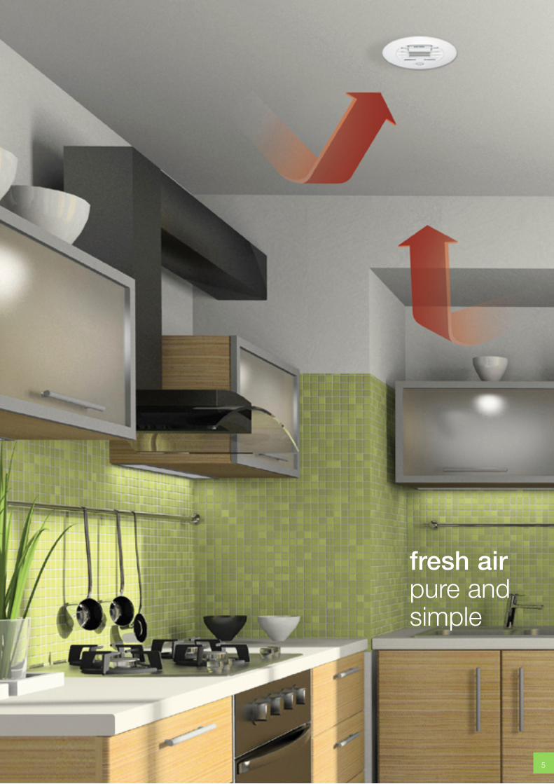
fresh airpure and simple
5

What are Systems
6 www.xpelair.co.uk
System ventilation
Mechanical extraction ventilation (MEV) can giveprecise, controlled, air extraction. It can take moistureand polluted air from area such as toilets, bathrooms,kitchens and utility rooms and vent it to the external atmosphere.Depending upon the building design and system requirements it canfeature either a single unit extracting internal air through ducts from anumber of wet rooms or it can have a separate fan running at a fastercontinuous extract rate in several locations in the house.
When mechanical ventilation is combined with heat recovery to giveMVHR - mechanical ventilation with heat recovery - it also givesexcellent energy conservation. As much as 90 per cent of the heat in the air being expelled from the building can be recovered to warm thefresh incoming air, with obvious benefits in terms of reduced energydemands and therefore lower fuel bills. Typically fuel bills lower by 5%and up to 10% on E.S.T. Best Practice (3 air tightness).
Xpelair (AEPL) offer and recommend system design services to provideefficient functional designs prior to installation.
Research and development
System ventilation is the answer to today’sventilation requirements - and tomorrow’s as well.The Government is committed to all new homes being‘zero carbon’ by 2016 and at Xpelair we are playingour part in meeting that commitment.We continue to invest in research and development to meet the rapidlychanging needs both of our professional customers and, ultimately, ofhouseholders.
Our focus is on delivering a healthy indoor climate withminimum cost, minimum energy use and the minimum impact on the global environment.
7
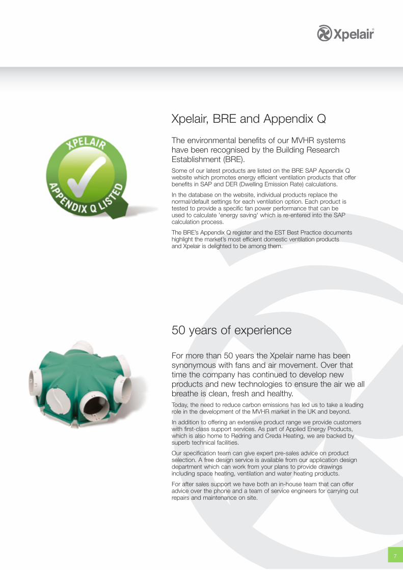
Xpelair, BRE and Appendix Q
The environmental benefits of our MVHR systems have been recognised by the Building ResearchEstablishment (BRE).Some of our latest products are listed on the BRE SAP Appendix Qwebsite which promotes energy efficient ventilation products that offerbenefits in SAP and DER (Dwelling Emission Rate) calculations.
In the database on the website, individual products replace thenormal/default settings for each ventilation option. Each product is tested to provide a specific fan power performance that can be used to calculate 'energy saving' which is re-entered into the SAPcalculation process.
The BRE’s Appendix Q register and the EST Best Practice documentshighlight the market’s most efficient domestic ventilation productsand Xpelair is delighted to be among them.
50 years of experience
For more than 50 years the Xpelair name has beensynonymous with fans and air movement. Over thattime the company has continued to develop newproducts and new technologies to ensure the air we allbreathe is clean, fresh and healthy. Today, the need to reduce carbon emissions has led us to take a leadingrole in the development of the MVHR market in the UK and beyond.
In addition to offering an extensive product range we provide customerswith first-class support services. As part of Applied Energy Products,which is also home to Redring and Creda Heating, we are backed bysuperb technical facilities.
Our specification team can give expert pre-sales advice on productselection. A free design service is available from our application designdepartment which can work from your plans to provide drawingsincluding space heating, ventilation and water heating products.
For after sales support we have both an in-house team that can offeradvice over the phone and a team of service engineers for carrying outrepairs and maintenance on site.
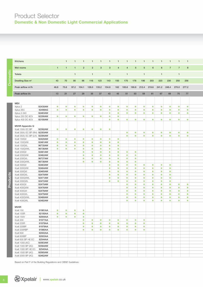
Product SelectorDomestic & Non Domestic Light Commercial Applications
8 www.xpelair.co.uk
Do
mes
ticP
rod
ucts
Kitchens 1 1 1 1 1 1 1 1 1 1 1 1 1 1 1
Wet rooms 1 1 1 2 2 3 3 4 4 5 5 6 6 7 7 8
Toilets 1 1 1 1 1 1 1
Dwelling Size m2 43 70 90 96 116 123 143 150 170 176 196 203 223 230 250 256
Peak airflow m3/h 46.8 75.6 97.2 104.1 126.0 133.2 154.8 162 183.6 190.8 212.4 219.6 241.2 248.4 270.0 277.2
Peak airflow l/s 13 21 27 29 35 37 43 45 51 53 59 61 67 69 75 77
MEVXplus 2 92430AW � � � � � � � � � � � � � � � �
Xplus 2EC 92498AG � � � � � � � � � � � � � � � �
Xplus 2-340 92483AW � � � � � � � � � �
Xplus 250 DC 8CV 92290AW � � � � � � � �
Xplus 400 DC 8CV 92100AW � � � � � � � � � �
MVHR Appendix QXcell 150U EC BP 92392AW � � � � � � �
Xcell 350U EC BP (RH) 92393AW � � � � � � � �
Xcell 350U EC BP (LH) 92395AW � � � � � � � �
Xcell 150QV 92420AW � � � � � � � �
Xcell 150QVW 92461AW � � � � � � � �
Xcell 150QVL 96735AW � � � � � � � �
Xcell 150QVWL 96736AW � � � � � � � �
Xcell 200QV 92461AW � � � � � � �
Xcell 200QVW 92462AW � � � � � � �
Xcell 200QVL 96737AW � � � � � � �
Xcell 200QVWL 96738AW � � � � � � �
Xcell 300QV 92463AW � � � � � � � �
Xcell 300QVW 92464AW � � � � � � � �
Xcell 300QVI 92465AW � � � � � � � �
Xcell 300QVL 92470AW � � � � � � � �
Xcell 300QVWL 92471AW � � � � � � � �
Xcell 300QVIL 92472AW � � � � � � � �
Xcell 400QV 92475AW � � � � � � � �
Xcell 400QVW 92476AW � � � � � � � �
Xcell 400QVI 92478AW � � � � � � � �
Xcell 400QVL 92479AW � � � � � � � �
Xcell 400QVWL 92480AW � � � � � � � �
Xcell 400QVIL 92482AW � � � � � � � �
MVHRXcell 150 91981AA � � � �
Xcell 150R 92100AA � � � �
Xcell 150V 92004AA � � � �
Xcell 200 91977AA � � � � � � � �
Xcell 200R 91978AA � � � � � � � �
Xcell 200BP 91979AA � � � � � � � �
Xcell 200RBP 91980AA � � � � � � � �
Xcell 600 92002AA
Xcell 600BP 92003AA
Xcell 600 BP HE EC 92544AA
Xcell 1000 (AC) 92563AW
Xcell 1000 BP (AC) 92564AW
Xcell 1000 BP HE EC 92545AA
Xcell 1500 BP (AC) 92565AW
Xcell 2000 BP (AC) 92462AW
Based on Part F of the Building Regulations and CIBSE Guidelines.
No
n-D
om
estic
9
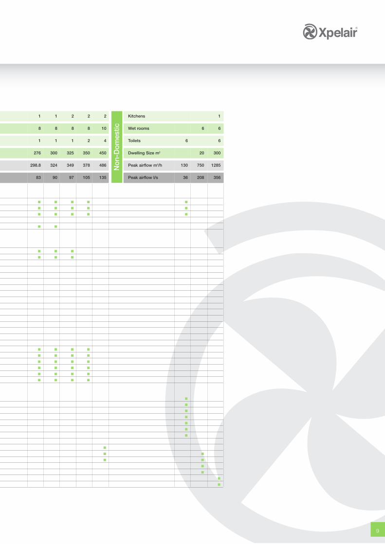
1 1 2 2 2 Kitchens 1
8 8 8 8 10 Wet rooms 6 6
1 1 1 2 4 Toilets 6 6
276 300 325 350 450 Dwelling Size m2 20 300
298.8 324 349 378 486 Peak airflow m3/h 130 750 1285
83 90 97 105 135 Peak airflow l/s 36 208 356
� � � � �
� � � � �
� � � � �
� �
� � �
� � �
� � � �
� � � �
� � � �
� � � �
� � � �
� � � �
�
�
�
�
�
�
�
�
� �
� �
�
�
�
�
MEV System Solutions
10 www.xpelair.co.uk
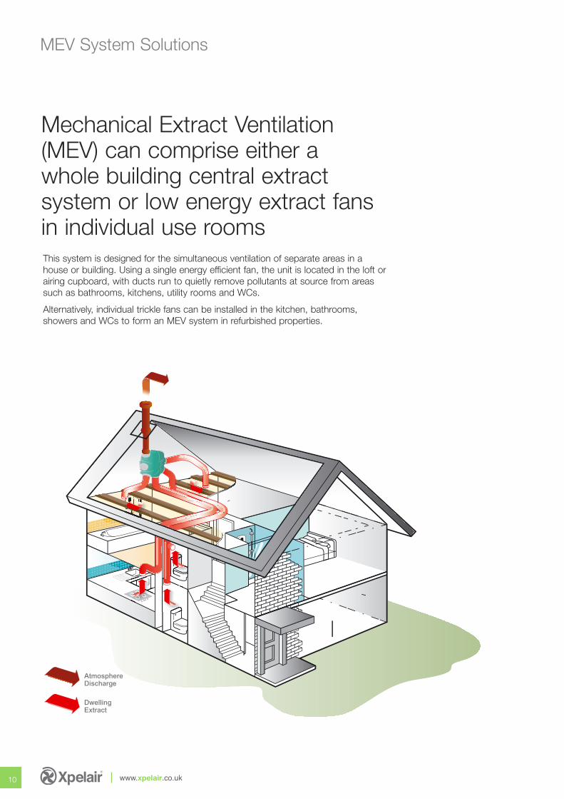
This system is designed for the simultaneous ventilation of separate areas in ahouse or building. Using a single energy efficient fan, the unit is located in the loft orairing cupboard, with ducts run to quietly remove pollutants at source from areassuch as bathrooms, kitchens, utility rooms and WCs.
Alternatively, individual trickle fans can be installed in the kitchen, bathrooms,showers and WCs to form an MEV system in refurbished properties.
AtmosphereDischarge
DwellingExtract
Mechanical Extract Ventilation(MEV) can comprise either awhole building central extractsystem or low energy extract fans in individual use rooms
11
fresh airpure and simple
12 www.xpelair.co.uk
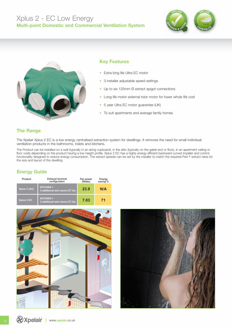
Xplus 2 - EC Low EnergyMulti-point Domestic and Commercial Ventilation System
The Xpelair Xplus 2 EC is a low energy centralised extraction system for dwellings. It removes the need for small individualventilation products in the bathrooms, toilets and kitchens.
The Product can be installed on a wall (typically in an airing cupboard), in the attic (typically on the gable end or floor), in an apartment ceiling orfloor voids depending on the product having a low height profile. Xplus 2 EC has a highly energy efficient backward curved impeller and controlfunctionality designed to reduce energy consumption. The extract speeds can be set by the installer to match the required Part F extract rates forthe size and layout of the dwelling.
Key Features
• Extra long life Ultra EC motor
• 3 installer adjustable speed settings
• Up to six 125mm Ø extract spigot connections
• Long life motor external rotor motor for lower whole life cost
• 5 year Ultra EC motor guarantee (UK)
• To suit apartments and average family homes
The Range
Energy GuideFan power
(Watts)Product Exhaust terminal
configuration
KITCHEN +3 additional wet rooms (37 l/s)
Xplus 2 (AC) 23.9
KITCHEN +3 additional wet rooms (37 l/s)
Xplus 2 EC 7.03
Energysaving %
N/A
71
13
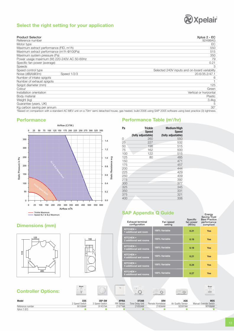
Select the right setting for your application
Trickle MaximumSpeed SL1 & SL2 Maximum
Trickle Speed Band
SL1 & SL2 Speed Band
Airflow m /h3
Sta
tic P
ress
ure
in P
a 250
300
350
150
200
0
50
100
Sta
tic R
esis
tan
ce w
.g
0.8
1.0
1.2
1.4
0.0
0.2
0.4
0.6
Airflow (C.F.M.)
0 25 50 75 100 125 150 175 200 225 250 275 300 325 350
0 25 100 150 200 250 300 350 400 450 500 550 600
Performance
SAP Appendix Q Guide EnergySaving TrustBest Practiceperformance
compliant
Specificfan power
(W/l/s)Fan speed
settingExhaust terminal
configuration
KITCHEN +1 additional wet room
100% Variable 0.21 Yes
KITCHEN +2 additional wet rooms
100% Variable 0.19 Yes
KITCHEN +3 additional wet rooms
100% Variable 0.19 Yes
KITCHEN +4 additional wet rooms
100% Variable 0.21 Yes
KITCHEN +5 additional wet rooms
100% Variable 0.24 Yes
KITCHEN +6 additional wet rooms
100% Variable 0.27 Yes
Performance Table (m3/hr)
Pa Trickle Medium/HighSpeed Speed
(fully adjustable) (fully adjustable)0 260 55025 227 53250 198 51575 162 500100 122 515125 80 485150 471175 457200 444225 429250 409275 392300 377325 345350 331375 321400 306
Product Selector Xplus 2 - ECReference number 92498AGMotor type ECMaximum extract performance (FID, m3/h) 550Maximum extract performance (m3/h @100Pa) 515Maximum system pressure (Pa) 350Power usage maximum (W) 220-240V AC 50-60Hz 79Specific fan power (average) 0.21Speeds 3Speed control type Selected 240V inputs and on-board variabilityNoise (dB(A)@3m) Speed 1/2/3 20.6/35.2/47.1Number of intake spigots 6Number of exhaust spigots 1Spigot diameter (mm) 125Colour GreenInstallation orientation Vertical or horizontalBody material PlasticWeight (kg) 3.4kgGuarantee (years, UK) 5Kg carbon saving per annum 30**Based on comparison with a standard AC MEV unit on a 79m2 semi detached house, gas heated, build 2006 using SAP 2005 software using best practice (3) tightness.
Dimensions (mm)
510
480
125190
Controller Options:
Model COS 3SP-SW XPIRA DT20B XRH AQS MOS2 Speed Switch 3 Speed Switch PIR Sensor Time Delay Unit Remote Humidistat Air Quality Sensor Manual Override Switch
Reference number 90108AW 91457AA 21871AA 21850AW 21856AW 92097AW 90199AWXplus 2 (EC) � � � � � � �
Xplus 250 / 400 DC 8CV Constant VolumeMulti-point Extract MEV Eight Selectable Speeds
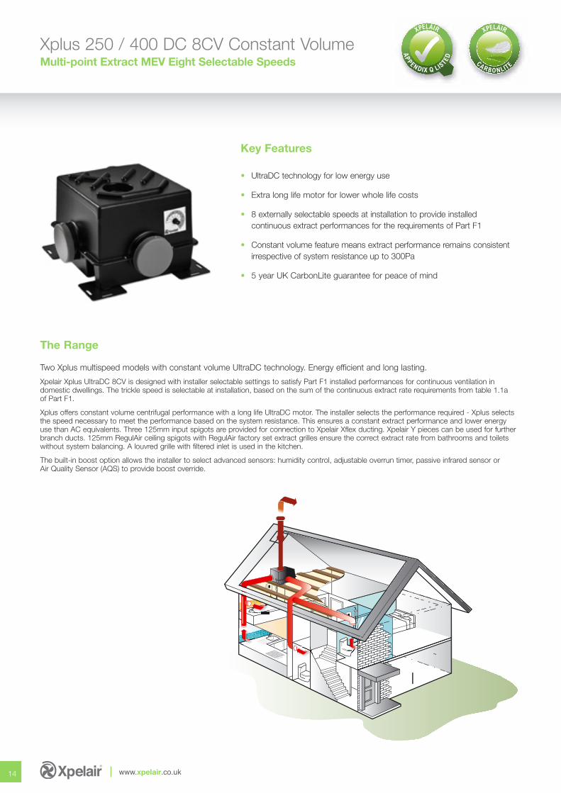
Two Xplus multispeed models with constant volume UltraDC technology. Energy efficient and long lasting.
Xpelair Xplus UltraDC 8CV is designed with installer selectable settings to satisfy Part F1 installed performances for continuous ventilation indomestic dwellings. The trickle speed is selectable at installation, based on the sum of the continuous extract rate requirements from table 1.1a of Part F1.
Xplus offers constant volume centrifugal performance with a long life UltraDC motor. The installer selects the performance required - Xplus selectsthe speed necessary to meet the performance based on the system resistance. This ensures a constant extract performance and lower energy use than AC equivalents. Three 125mm input spigots are provided for connection to Xpelair Xflex ducting. Xpelair Y pieces can be used for furtherbranch ducts. 125mm RegulAir ceiling spigots with RegulAir factory set extract grilles ensure the correct extract rate from bathrooms and toiletswithout system balancing. A louvred grille with filtered inlet is used in the kitchen.
The built-in boost option allows the installer to select advanced sensors: humidity control, adjustable overrun timer, passive infrared sensor orAir Quality Sensor (AQS) to provide boost override.
Key Features
• UltraDC technology for low energy use
• Extra long life motor for lower whole life costs
• 8 externally selectable speeds at installation to provide installed continuous extract performances for the requirements of Part F1
• Constant volume feature means extract performance remains consistent irrespective of system resistance up to 300Pa
• 5 year UK CarbonLite guarantee for peace of mind
14 www.xpelair.co.uk
The Range
Select the right setting for your application
15
Performance
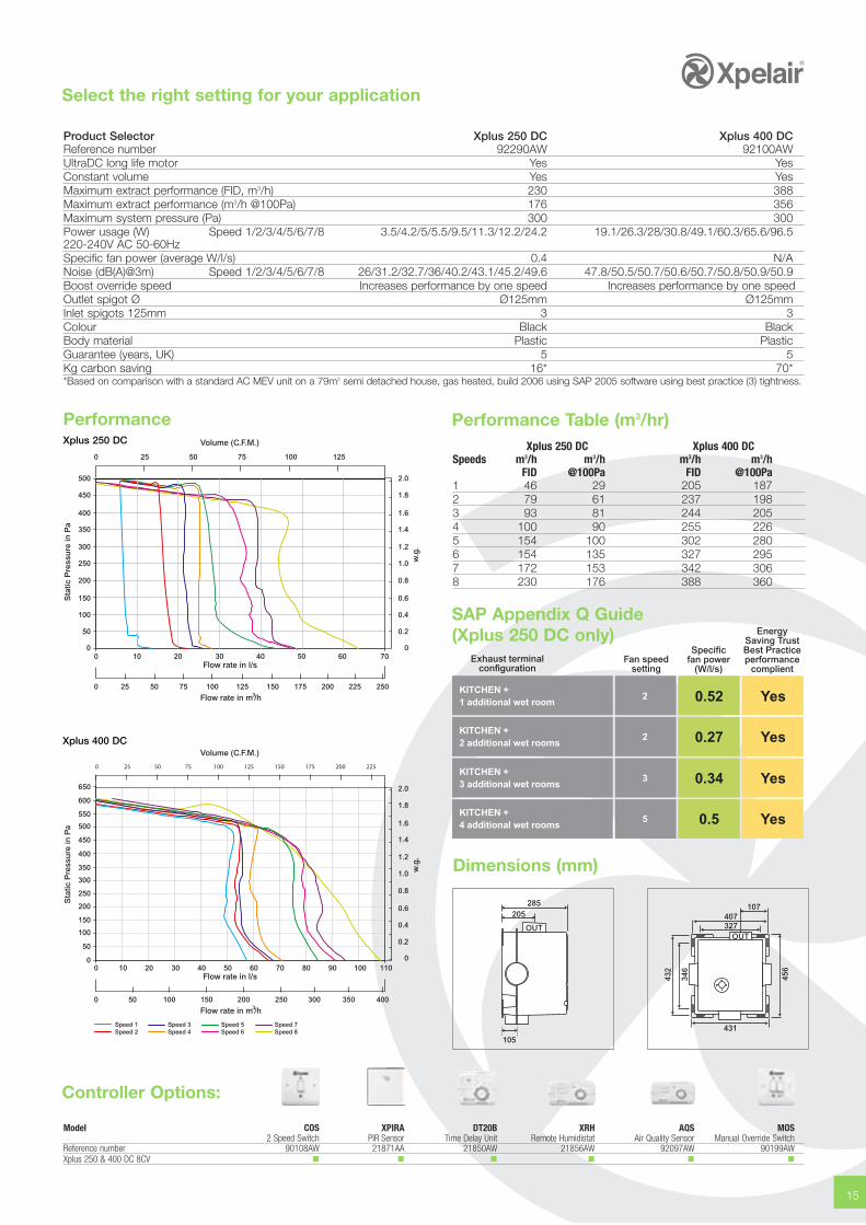
Product Selector Xplus 250 DC Xplus 400 DCReference number 92290AW 92100AWUltraDC long life motor Yes YesConstant volume Yes YesMaximum extract performance (FID, m3/h) 230 388Maximum extract performance (m3/h @100Pa) 176 356Maximum system pressure (Pa) 300 300Power usage (W) Speed 1/2/3/4/5/6/7/8 3.5/4.2/5/5.5/9.5/11.3/12.2/24.2 19.1/26.3/28/30.8/49.1/60.3/65.6/96.5220-240V AC 50-60HzSpecific fan power (average W/l/s) 0.4 N/ANoise (dB(A)@3m) Speed 1/2/3/4/5/6/7/8 26/31.2/32.7/36/40.2/43.1/45.2/49.6 47.8/50.5/50.7/50.6/50.7/50.8/50.9/50.9Boost override speed Increases performance by one speed Increases performance by one speedOutlet spigot Ø Ø125mm Ø125mmInlet spigots 125mm 3 3Colour Black BlackBody material Plastic PlasticGuarantee (years, UK) 5 5Kg carbon saving 16* 70**Based on comparison with a standard AC MEV unit on a 79m2 semi detached house, gas heated, build 2006 using SAP 2005 software using best practice (3) tightness.
Xplus 250 DC
0
50
100
150
200
250
300
350
400
450
500
0
0.2
0.4
0.6
0.8
1.0
1.2
1.4
1.6
1.8
2.0
0 10 20 30 40 50 60 70
Sta
tic P
ress
ure
in P
a
w.g
.
0 25 50 75 100 125
0 25 50 75 150 200 225 250100 125 175
Volume (C.F.M.)
Flow rate in l/s
Flow rate in m /h3
Sta
tic P
ress
ure
in P
a
Volume (C.F.M.)
0
50
100
150
200
250
300
350
400
450
500
550
600
650
0 10 20 30 40 50 60 70 80 90 100 110
0 10050 250 350 400150 200 300
Flow rate in l/s
Flow rate in m /h3
Speed 1Speed 2
Speed 3Speed 4
Speed 5Speed 6
Speed 7Speed 8
0
0.2
0.4
0.6
0.8
1.0
1.2
1.4
1.6
1.8
2.0
w.g
.
Xplus 400 DC
Dimensions (mm)
285205
105
OUT407327
431
456
432
346
107
OUT
Performance Table (m3/hr)Xplus 250 DC Xplus 400 DC
Speeds m3/h m3/h m3/h m3/hFID @100Pa FID @100Pa
1 46 29 205 1872 79 61 237 1983 93 81 244 2054 100 90 255 2265 154 100 302 2806 154 135 327 2957 172 153 342 3068 230 176 388 360
SAP Appendix Q Guide(Xplus 250 DC only) Energy
Saving TrustBest Practiceperformance
complient
Specificfan power
(W/l/s)Fan speed
settingExhaust terminal
configuration
KITCHEN +1 additional wet room
2 0.52 Yes
KITCHEN +2 additional wet rooms
2 0.27 Yes
KITCHEN +3 additional wet rooms
3 0.34 Yes
KITCHEN +4 additional wet rooms
5 0.5 Yes
Controller Options:
Model COS XPIRA DT20B XRH AQS MOS2 Speed Switch PIR Sensor Time Delay Unit Remote Humidistat Air Quality Sensor Manual Override Switch
Reference number 90108AW 21871AA 21850AW 21856AW 92097AW 90199AWXplus 250 & 400 DC 8CV � � � � � �
Xplus 2 (AC)Multi-point Domestic and Commercial Ventilation System
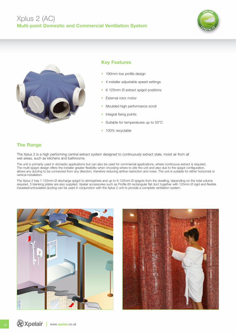
The Xplus 2 is a high performing central extract system designed to continuously extract stale, moist air from allwet areas, such as kitchens and bathrooms.
The unit is primarily used in domestic applications but can also be used for commercial applications, where continuous extract is required.The multi-spigot design offers the installer greater flexibility when choosing where to site the unit and also due to the spigot configuration,allows any ducting to be connected from any direction, therefore reducing airflow restriction and noise. The unit is suitable for either horizontal orvertical installation.
The Xplus 2 has 1-125mm Ø discharge spigot to atmosphere and up to 6-125mm Ø spigots from the dwelling, depending on the total volumerequired. 3 blanking plates are also supplied. Xpelair accessories such as Profile 60 rectangular flat duct together with 125mm Ø rigid and flexibleinsulated/uninsulated ducting can be used in conjunction with the Xplus 2 unit to provide a complete ventilation system.
Key Features
• 190mm low profile design
• 4 installer adjustable speed settings
• 6 125mm Ø extract spigot positions
• External rotor motor
• Moulded high performance scroll
• Integral fixing points
• Suitable for temperatures up to 50°C
• 100% recyclable
16 www.xpelair.co.uk
The Range
Select the right setting for your application
17
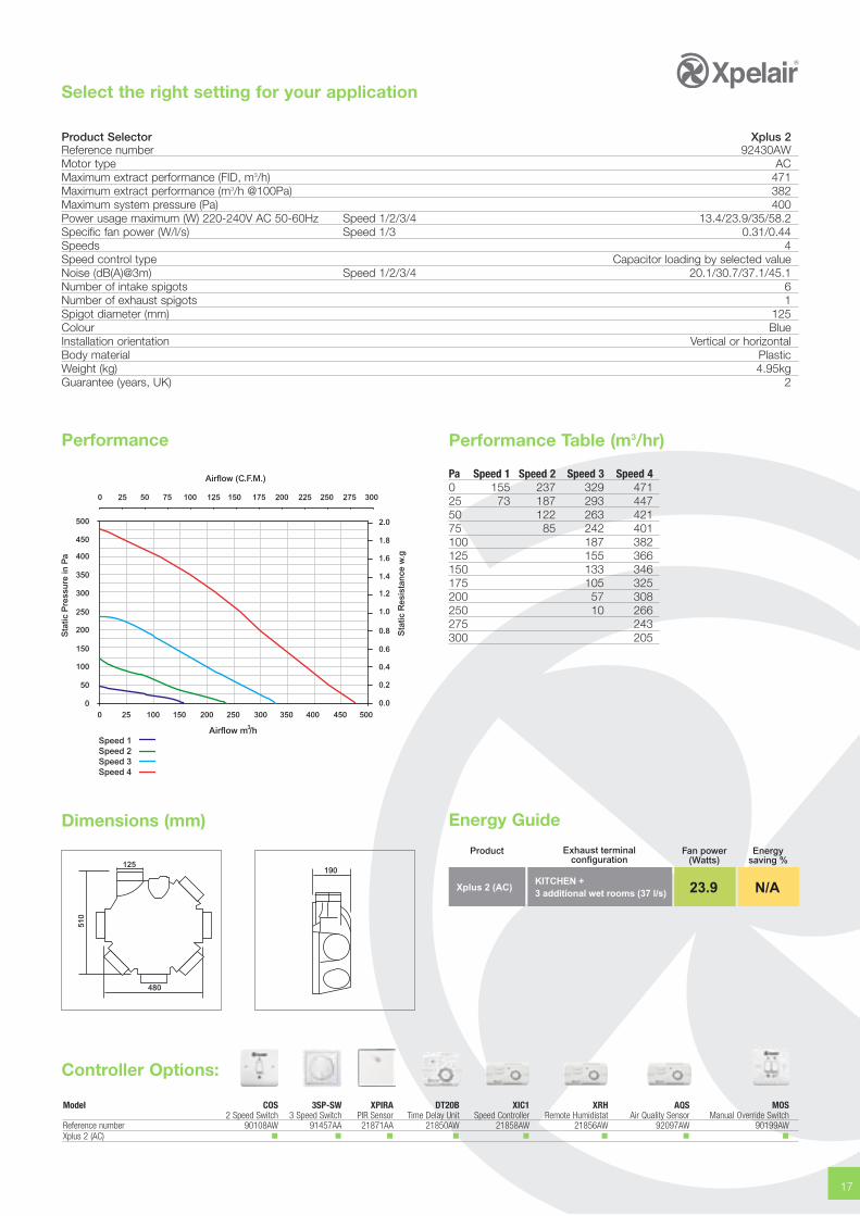
Product Selector Xplus 2Reference number 92430AWMotor type ACMaximum extract performance (FID, m3/h) 471Maximum extract performance (m3/h @100Pa) 382Maximum system pressure (Pa) 400Power usage maximum (W) 220-240V AC 50-60Hz Speed 1/2/3/4 13.4/23.9/35/58.2Specific fan power (W/l/s) Speed 1/3 0.31/0.44Speeds 4Speed control type Capacitor loading by selected valueNoise (dB(A)@3m) Speed 1/2/3/4 20.1/30.7/37.1/45.1Number of intake spigots 6Number of exhaust spigots 1Spigot diameter (mm) 125Colour BlueInstallation orientation Vertical or horizontalBody material PlasticWeight (kg) 4.95kgGuarantee (years, UK) 2
Performance
Dimensions (mm)
510
480
125190
Performance Table (m3/hr)
Pa Speed 1 Speed 2 Speed 3 Speed 40 155 237 329 47125 73 187 293 44750 122 263 42175 85 242 401100 187 382125 155 366150 133 346175 105 325200 57 308250 10 266275 243300 205
Airflow m /h3
Sta
tic P
ress
ure
in P
a
450
500
250
300
350
400
150
200
0
50
100
Sta
tic R
esis
tan
ce w
.g
0.8
1.0
1.2
1.4
1.6
1.8
0.0
0.2
0.4
0.6
2.0
Airflow (C.F.M.)
0 25 50 75 100 125 150 175 200 225 250 275 300
0 25 100 150 200 250 300 350 400 450 500
Speed 1Speed 2Speed 3Speed 4
Controller Options:
Model COS 3SP-SW XPIRA DT20B XIC1 XRH AQS MOS2 Speed Switch 3 Speed Switch PIR Sensor Time Delay Unit Speed Controller Remote Humidistat Air Quality Sensor Manual Override Switch
Reference number 90108AW 91457AA 21871AA 21850AW 21858AW 21856AW 92097AW 90199AWXplus 2 (AC) � � � � � � � �
Energy Guide
Fan power(Watts)
Product Exhaust terminalconfiguration
KITCHEN +3 additional wet rooms (37 l/s)
Xplus 2 (AC) 23.9
Energysaving %
N/A
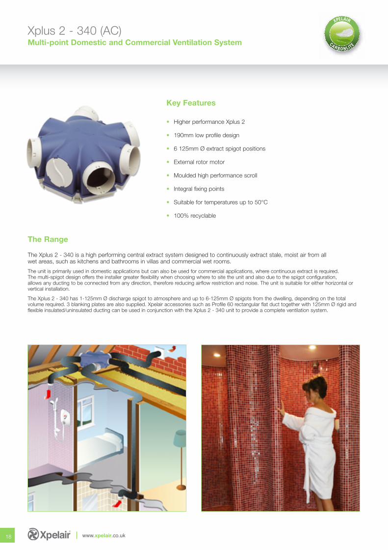
Xplus 2 - 340 (AC)Multi-point Domestic and Commercial Ventilation System
The Xplus 2 - 340 is a high performing central extract system designed to continuously extract stale, moist air from allwet areas, such as kitchens and bathrooms in villas and commercial wet rooms.
The unit is primarily used in domestic applications but can also be used for commercial applications, where continuous extract is required.The multi-spigot design offers the installer greater flexibility when choosing where to site the unit and also due to the spigot configuration,allows any ducting to be connected from any direction, therefore reducing airflow restriction and noise. The unit is suitable for either horizontal orvertical installation.
The Xplus 2 - 340 has 1-125mm Ø discharge spigot to atmosphere and up to 6-125mm Ø spigots from the dwelling, depending on the totalvolume required. 3 blanking plates are also supplied. Xpelair accessories such as Profile 60 rectangular flat duct together with 125mm Ø rigid andflexible insulated/uninsulated ducting can be used in conjunction with the Xplus 2 - 340 unit to provide a complete ventilation system.
Key Features
• Higher performance Xplus 2
• 190mm low profile design
• 6 125mm Ø extract spigot positions
• External rotor motor
• Moulded high performance scroll
• Integral fixing points
• Suitable for temperatures up to 50°C
• 100% recyclable
18 www.xpelair.co.uk
The Range
Select the right setting for your application
19
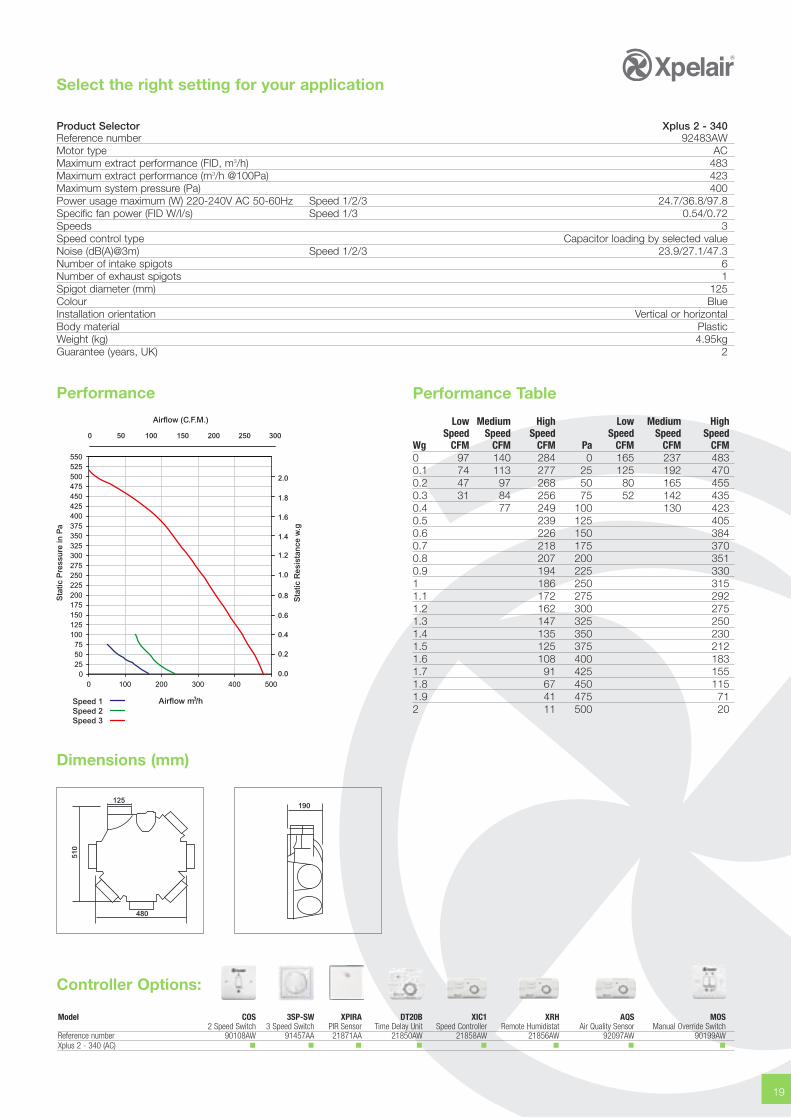
Product Selector Xplus 2 - 340Reference number 92483AWMotor type ACMaximum extract performance (FID, m3/h) 483Maximum extract performance (m3/h @100Pa) 423Maximum system pressure (Pa) 400Power usage maximum (W) 220-240V AC 50-60Hz Speed 1/2/3 24.7/36.8/97.8Specific fan power (FID W/l/s) Speed 1/3 0.54/0.72Speeds 3Speed control type Capacitor loading by selected valueNoise (dB(A)@3m) Speed 1/2/3 23.9/27.1/47.3Number of intake spigots 6Number of exhaust spigots 1Spigot diameter (mm) 125Colour BlueInstallation orientation Vertical or horizontalBody material PlasticWeight (kg) 4.95kgGuarantee (years, UK) 2
Performance
Dimensions (mm)
510
480
125190
Performance Table
Low Medium High Low Medium HighSpeed Speed Speed Speed Speed Speed
Wg CFM CFM CFM Pa CFM CFM CFM0 97 140 284 0 165 237 4830.1 74 113 277 25 125 192 4700.2 47 97 268 50 80 165 4550.3 31 84 256 75 52 142 4350.4 77 249 100 130 4230.5 239 125 4050.6 226 150 3840.7 218 175 3700.8 207 200 3510.9 194 225 3301 186 250 3151.1 172 275 2921.2 162 300 2751.3 147 325 2501.4 135 350 2301.5 125 375 2121.6 108 400 1831.7 91 425 1551.8 67 450 1151.9 41 475 712 11 500 20
0255075100125150175200225250275300325350375400425450475500525550
0 100 200 300 400 500
0 50 100 150 200 250 300
Airflow m /h3
Sta
tic P
ress
ure
in P
a
Sta
tic R
esis
tan
ce w
.g
Airflow (C.F.M.)
0.8
1.0
1.2
1.4
1.6
1.8
0.0
0.2
0.4
0.6
2.0
Speed 1Speed 2Speed 3
Controller Options:
Model COS 3SP-SW XPIRA DT20B XIC1 XRH AQS MOS2 Speed Switch 3 Speed Switch PIR Sensor Time Delay Unit Speed Controller Remote Humidistat Air Quality Sensor Manual Override Switch
Reference number 90108AW 91457AA 21871AA 21850AW 21858AW 21856AW 92097AW 90199AWXplus 2 - 340 (AC) � � � � � � � �
20 www.xpelair.co.uk
MVHR System Solutions
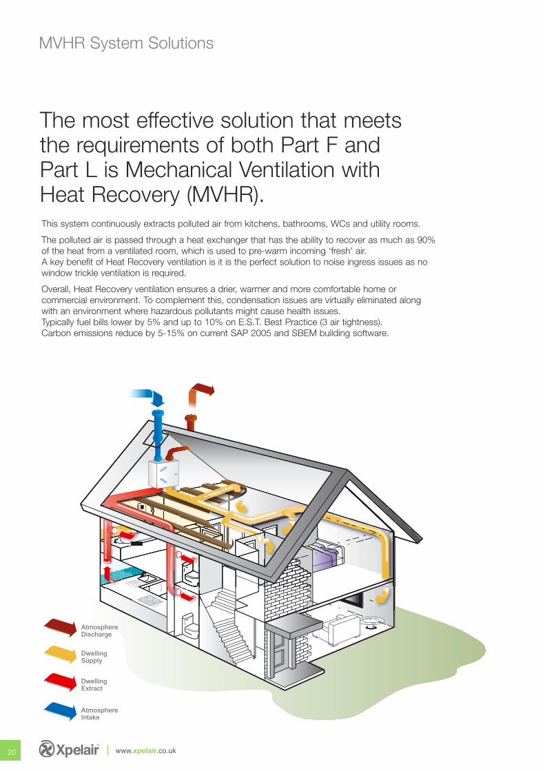
This system continuously extracts polluted air from kitchens, bathrooms, WCs and utility rooms.
The polluted air is passed through a heat exchanger that has the ability to recover as much as 90%of the heat from a ventilated room, which is used to pre-warm incoming ‘fresh’ air. A key benefit of Heat Recovery ventilation is it is the perfect solution to noise ingress issues as nowindow trickle ventilation is required.
Overall, Heat Recovery ventilation ensures a drier, warmer and more comfortable home orcommercial environment. To complement this, condensation issues are virtually eliminated alongwith an environment where hazardous pollutants might cause health issues.Typically fuel bills lower by 5% and up to 10% on E.S.T. Best Practice (3 air tightness).Carbon emissions reduce by 5-15% on current SAP 2005 and SBEM building software.
The most effective solution that meetsthe requirements of both Part F andPart L is Mechanical Ventilation withHeat Recovery (MVHR).
AtmosphereDischarge
DwellingSupply
DwellingExtract
AtmosphereIntake
21
fresh airpure and simple
AtmosphereDischarge
DwellingSupply
AtmosphereIntake
4-125mm ØSpigots
DwellingExtract
Xcell 150QV / QVW
Key Features
• Ultra EC technology for low energy use
• High efficiency counterflow cell with up to 90% efficiency
• EPP high structural integral body
• G4 filters
• The unit is supplied with a 1m length of 20mm Ø (O/D) plastic condensate tubing
• SAP Appendix Q Listed
• Ultra EC technology for low energy use
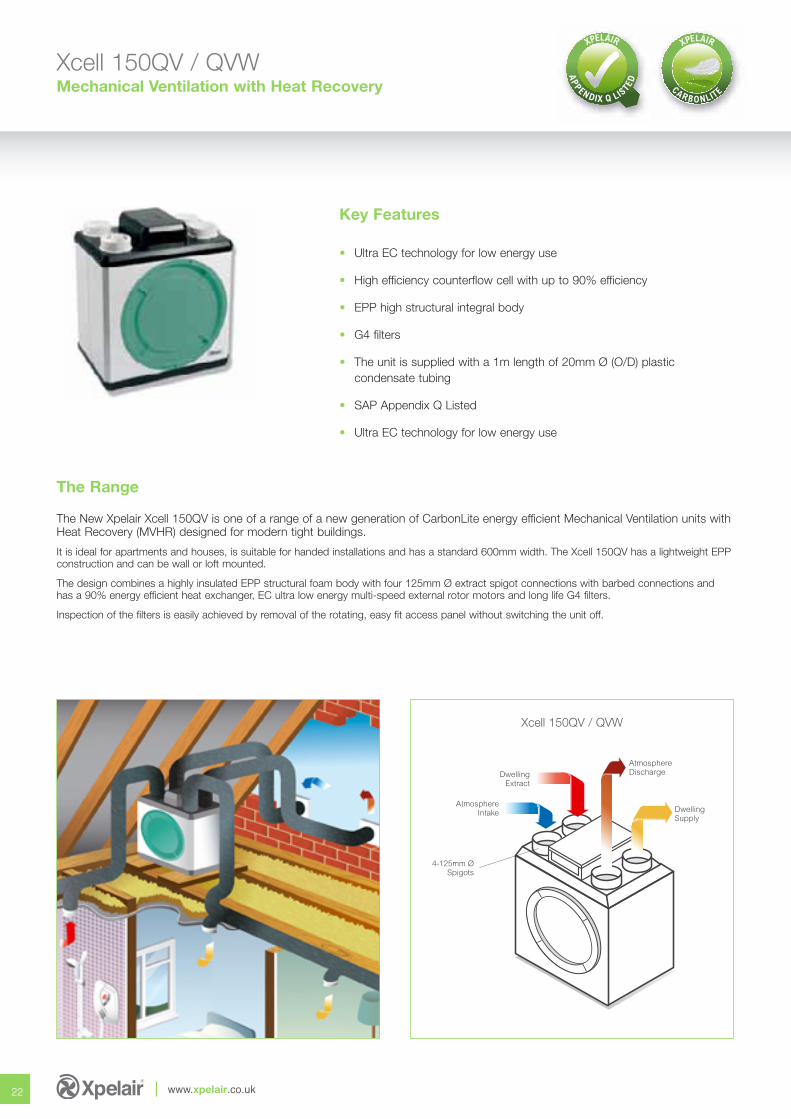
Xcell 150QV / QVWMechanical Ventilation with Heat Recovery
The New Xpelair Xcell 150QV is one of a range of a new generation of CarbonLite energy efficient Mechanical Ventilation units withHeat Recovery (MVHR) designed for modern tight buildings.
It is ideal for apartments and houses, is suitable for handed installations and has a standard 600mm width. The Xcell 150QV has a lightweight EPPconstruction and can be wall or loft mounted.
The design combines a highly insulated EPP structural foam body with four 125mm Ø extract spigot connections with barbed connections and has a 90% energy efficient heat exchanger, EC ultra low energy multi-speed external rotor motors and long life G4 filters.
Inspection of the filters is easily achieved by removal of the rotating, easy fit access panel without switching the unit off.
22 www.xpelair.co.uk
The Range
Select the right setting for your application
23
Speed 1Speed 2
Airflow m /h3
Airflow (C.F.M.)
Sta
tic P
ress
ure
in P
a
Sta
tic R
esis
tan
ce w
.g
0 50 100 150 200 250
0 25 50 75 100 125 150
0
25
50
75
100
125
150
175
200
225
250
275
300
0
0.1
0.2
0.3
0.4
0.5
0.6
0.7
0.8
0.9
1.0
1.1
1.2
Performance Band
Performance
Controller Options:
Dimensions (mm)
4-Ø125Spigots
Side View
425Front View
600
42 8559
5
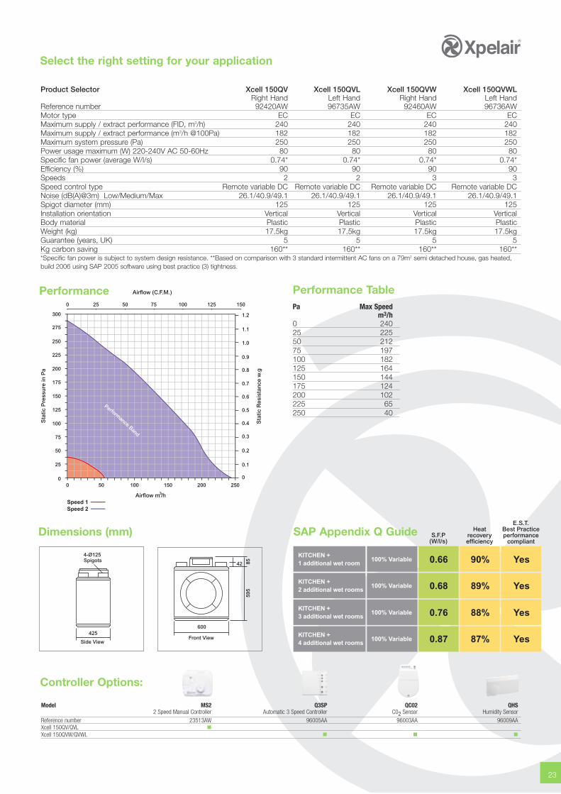
Performance Table
SAP Appendix Q Guide
Pa Max Speedm3/h
0 24025 22550 21275 197100 182125 164150 144175 124200 102225 65250 40
Heatrecoveryefficiency
S.F.P(W/l/s)
KITCHEN +1 additional wet room
100% Variable 0.66 90%
KITCHEN +2 additional wet rooms
100% Variable 0.68 89%
KITCHEN +3 additional wet rooms
100% Variable 0.76 88%
KITCHEN +4 additional wet rooms
100% Variable 0.87 87%
E.S.T.Best Practiceperformance
compliant
Yes
Yes
Yes
Yes
Model MS2 Q3SP QC02 QHS2 Speed Manual Controller Automatic 3 Speed Controller C02 Sensor Humidity Sensor
Reference number 23513AW 96005AA 96003AA 96009AAXcell 150QV/QVL �Xcell 150QVW/QVWL � � �
Product Selector Xcell 150QV Xcell 150QVL Xcell 150QVW Xcell 150QVWLRight Hand Left Hand Right Hand Left Hand
Reference number 92420AW 96735AW 92460AW 96736AWMotor type EC EC EC ECMaximum supply / extract performance (FID, m3/h) 240 240 240 240Maximum supply / extract performance (m3/h @100Pa) 182 182 182 182Maximum system pressure (Pa) 250 250 250 250Power usage maximum (W) 220-240V AC 50-60Hz 80 80 80 80Specific fan power (average W/l/s) 0.74* 0.74* 0.74* 0.74*Efficiency (%) 90 90 90 90Speeds 2 2 3 3Speed control type Remote variable DC Remote variable DC Remote variable DC Remote variable DCNoise (dB(A)@3m) Low/Medium/Max 26.1/40.9/49.1 26.1/40.9/49.1 26.1/40.9/49.1 26.1/40.9/49.1Spigot diameter (mm) 125 125 125 125Installation orientation Vertical Vertical Vertical VerticalBody material Plastic Plastic Plastic PlasticWeight (kg) 17.5kg 17.5kg 17.5kg 17.5kgGuarantee (years, UK) 5 5 5 5Kg carbon saving 160** 160** 160** 160***Specific fan power is subject to system design resistance. **Based on comparison with 3 standard intermittent AC fans on a 79m2 semi detached house, gas heated,build 2006 using SAP 2005 software using best practice (3) tightness.
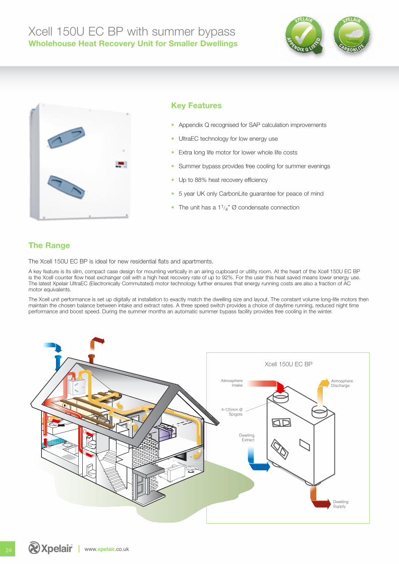
Xcell 150U EC BP with summer bypassWholehouse Heat Recovery Unit for Smaller Dwellings
The Xcell 150U EC BP is ideal for new residential flats and apartments.
A key feature is its slim, compact case design for mounting vertically in an airing cupboard or utility room. At the heart of the Xcell 150U EC BP is the Xcell counter flow heat exchanger cell with a high heat recovery rate of up to 92%. For the user this heat saved means lower energy use. The latest Xpelair UltraEC (Electronically Commutated) motor technology further ensures that energy running costs are also a fraction of AC motor equivalents.
The Xcell unit performance is set up digitally at installation to exactly match the dwelling size and layout. The constant volume long-life motors thenmaintain the chosen balance between intake and extract rates. A three speed switch provides a choice of daytime running, reduced night timeperformance and boost speed. During the summer months an automatic summer bypass facility provides free cooling in the winter.
Key Features
• Appendix Q recognised for SAP calculation improvements
• UltraEC technology for low energy use
• Extra long life motor for lower whole life costs
• Summer bypass provides free cooling for summer evenings
• Up to 88% heat recovery efficiency
• 5 year UK only CarbonLite guarantee for peace of mind
• The unit has a 11/4” Ø condensate connection
24 www.xpelair.co.uk
4-125mm ØSpigots
AtmosphereDischarge
DwellingSupply
DwellingExtract
AtmosphereIntake
Xcell 150U EC BP
The Range
Select the right setting for your application
25
Performance
Airflow m /h3
Sta
tic P
ress
ure
in P
a
Sta
tic R
esis
tan
ce w
.g
Airflow (C.F.M.)
0 20 40 60 80 100 120 140 160 180
0 10 20 30 40 50 60 70 80 90 100
0
100
300
400
500
0
0.4
0.8
1.2
1.6
Speed 1 (holiday/absent)Speed 2 (normal)Speed 3 (boost)
Performance Band
C.F.M. Cubic feet per minuteIn. wg Inches water gauge
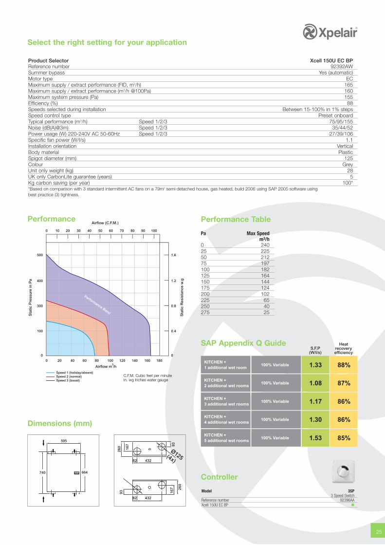
Product Selector Xcell 150U EC BPReference number 92392AWSummer bypass Yes (automatic)Motor type ECMaximum supply / extract performance (FID, m3/h) 165Maximum supply / extract performance (m3/h @100Pa) 160Maximum system pressure (Pa) 155Efficiency (%) 88Speeds selected during installation Between 15-100% in 1% stepsSpeed control type Preset onboardTypical performance (m3/h) Speed 1/2/3 75/95/155Noise (dB(A)@3m) Speed 1/2/3 35/44/52Power usage (W) 220-240V AC 50-60Hz Speed 1/2/3 27/39/106Specific fan power (W/l/s) 1.1Installation orientation VerticalBody material PlasticSpigot diameter (mm) 125Colour GreyUnit only weight (kg) 28 UK only CarbonLite guarantee (years) 5 Kg carbon saving (per year) 100**Based on comparison with 3 standard intermittent AC fans on a 79m2 semi detached house, gas heated, build 2006 using SAP 2005 software usingbest practice (3) tightness.
Dimensions (mm)
664740
595
43282
93
260
167
93
167
82 432
260
Heatrecoveryefficiency
S.F.P(W/l/s)
KITCHEN +1 additional wet room
100% Variable 1.33 88%
KITCHEN +2 additional wet rooms
100% Variable 1.08 87%
KITCHEN +3 additional wet rooms
100% Variable 1.17 86%
KITCHEN +4 additional wet rooms
100% Variable 1.30 86%
KITCHEN +5 additional wet rooms
100% Variable 1.53 85%
SAP Appendix Q Guide
Performance Table
Pa Max Speedm3/h
0 24025 22550 21275 197100 182125 164150 144175 124200 102225 65250 40275 25
Controller
Model 3SP3 Speed Switch
Reference number 92396AAXcell 150U EC BP �
AtmosphereDischarge
DwellingSupply
AtmosphereIntake
4-125mm ØSpigots
DwellingExtract
Xcell 200QV
Key Features
• Ultra EC technology for low energy use
• High efficiency counterflow cell with up to 90% efficiency
• EPP high structural integral body
• G4 filters
• The unit is supplied with a 1m length of 20mm Ø (O/D) plastic condensate tubing
• SAP Appendix Q Listed
• Ultra EC technology for low energy use
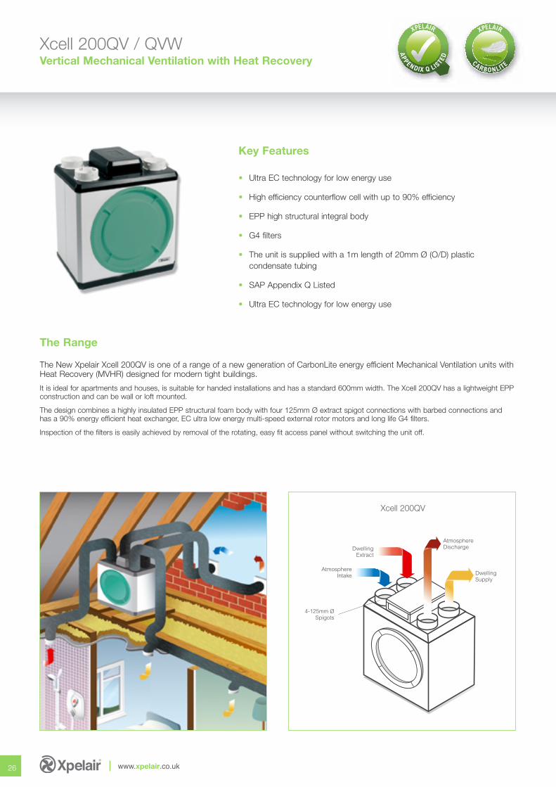
Xcell 200QV / QVWVertical Mechanical Ventilation with Heat Recovery
The New Xpelair Xcell 200QV is one of a range of a new generation of CarbonLite energy efficient Mechanical Ventilation units withHeat Recovery (MVHR) designed for modern tight buildings.
It is ideal for apartments and houses, is suitable for handed installations and has a standard 600mm width. The Xcell 200QV has a lightweight EPPconstruction and can be wall or loft mounted.
The design combines a highly insulated EPP structural foam body with four 125mm Ø extract spigot connections with barbed connections and has a 90% energy efficient heat exchanger, EC ultra low energy multi-speed external rotor motors and long life G4 filters.
Inspection of the filters is easily achieved by removal of the rotating, easy fit access panel without switching the unit off.
26 www.xpelair.co.uk
The Range
Select the right setting for your application
27
Airflow m /h3
Airflow (C.F.M.)
Sta
tic P
ress
ure
in P
a
540520500480460440420400380360340320300280260240220200180160140120100
80604020
00 10 20 30 40 50 60 70 80 90 100 110 120 130 140 150 160 170 180 190 200 210 220 230 240 250
Performance Band
Performance
Dimensions (mm)
4-Ø125Spigots
Side View
425Front View
600
42 8559
5
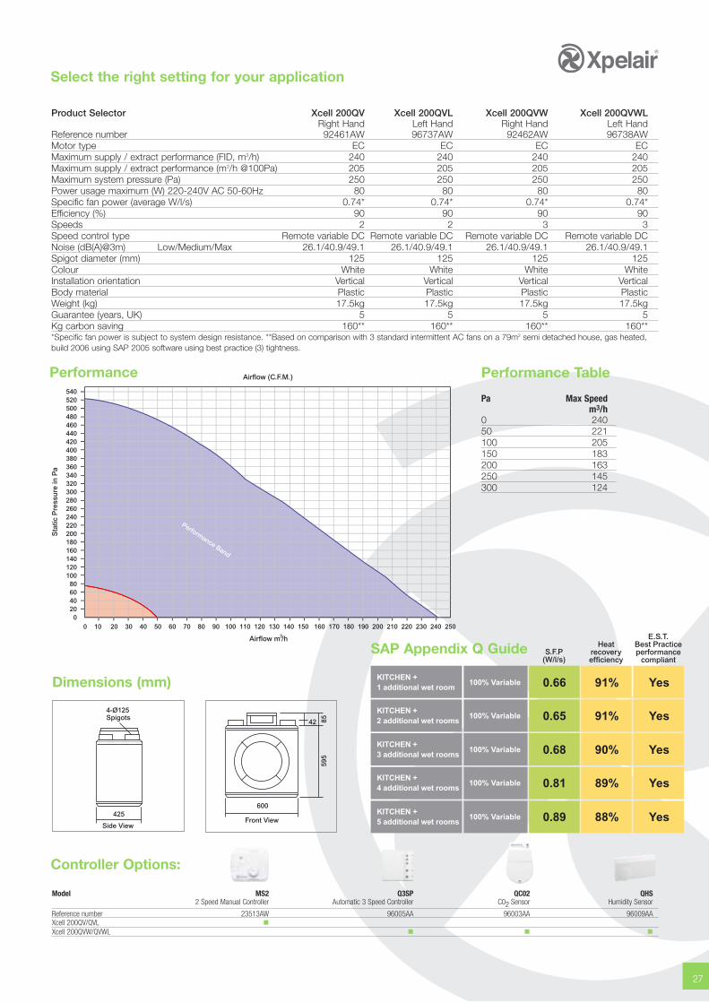
Performance Table
SAP Appendix Q Guide
Pa Max Speedm3/h
0 24050 221100 205150 183200 163250 145300 124
Heatrecoveryefficiency
S.F.P(W/l/s)
KITCHEN +1 additional wet room
100% Variable 0.66 91%
KITCHEN +2 additional wet rooms
100% Variable 0.65 91%
KITCHEN +3 additional wet rooms
100% Variable 0.68 90%
KITCHEN +4 additional wet rooms
100% Variable 0.81 89%
E.S.T.Best Practiceperformance
compliant
Yes
Yes
Yes
Yes
KITCHEN +5 additional wet rooms
100% Variable 0.89 88% Yes
Product Selector Xcell 200QV Xcell 200QVL Xcell 200QVW Xcell 200QVWLRight Hand Left Hand Right Hand Left Hand
Reference number 92461AW 96737AW 92462AW 96738AWMotor type EC EC EC ECMaximum supply / extract performance (FID, m3/h) 240 240 240 240Maximum supply / extract performance (m3/h @100Pa) 205 205 205 205Maximum system pressure (Pa) 250 250 250 250Power usage maximum (W) 220-240V AC 50-60Hz 80 80 80 80Specific fan power (average W/l/s) 0.74* 0.74* 0.74* 0.74*Efficiency (%) 90 90 90 90Speeds 2 2 3 3Speed control type Remote variable DC Remote variable DC Remote variable DC Remote variable DCNoise (dB(A)@3m) Low/Medium/Max 26.1/40.9/49.1 26.1/40.9/49.1 26.1/40.9/49.1 26.1/40.9/49.1Spigot diameter (mm) 125 125 125 125Colour White White White WhiteInstallation orientation Vertical Vertical Vertical VerticalBody material Plastic Plastic Plastic PlasticWeight (kg) 17.5kg 17.5kg 17.5kg 17.5kgGuarantee (years, UK) 5 5 5 5Kg carbon saving 160** 160** 160** 160***Specific fan power is subject to system design resistance. **Based on comparison with 3 standard intermittent AC fans on a 79m2 semi detached house, gas heated,build 2006 using SAP 2005 software using best practice (3) tightness.
Controller Options:
Model MS2 Q3SP QC02 QHS2 Speed Manual Controller Automatic 3 Speed Controller C02 Sensor Humidity Sensor
Reference number 23513AW 96005AA 96003AA 96009AAXcell 200QV/QVL �Xcell 200QVW/QVWL � � �
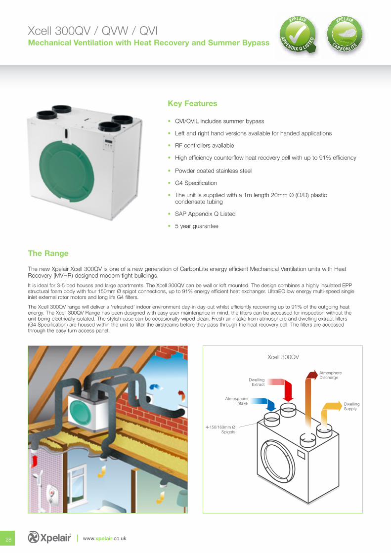
Xcell 300QV / QVW / QVIMechanical Ventilation with Heat Recovery and Summer Bypass
The new Xpelair Xcell 300QV is one of a new generation of CarbonLite energy efficient Mechanical Ventilation units with HeatRecovery (MVHR) designed modern tight buildings.
It is ideal for 3-5 bed houses and large apartments. The Xcell 300QV can be wall or loft mounted. The design combines a highly insulated EPPstructural foam body with four 150mm Ø spigot connections, up to 91% energy efficient heat exchanger. UltraEC low energy multi-speed singleinlet external rotor motors and long life G4 filters.
The Xcell 300QV range will deliver a ‘refreshed’ indoor environment day-in day-out whilst efficiently recovering up to 91% of the outgoing heat energy. The Xcell 300QV Range has been designed with easy user maintenance in mind, the filters can be accessed for inspection without the unit being electrically isolated. The stylish case can be occasionally wiped clean. Fresh air intake from atmosphere and dwelling extract filters (G4 Specification) are housed within the unit to filter the airstreams before they pass through the heat recovery cell. The filters are accessed through the easy turn access panel.
Key Features
• QVI/QVIL includes summer bypass
• Left and right hand versions available for handed applications
• RF controllers available
• High efficiency counterflow heat recovery cell with up to 91% efficiency
• Powder coated stainless steel
• G4 Specification
• The unit is supplied with a 1m length 20mm Ø (O/D) plastic condensate tubing
• SAP Appendix Q Listed
• 5 year guarantee
28 www.xpelair.co.uk
AtmosphereDischarge
DwellingSupply
DwellingExtract
AtmosphereIntake
4-150/160mm ØSpigots
The Range
Xcell 300QV
Select the right setting for your application
29
Volume (C.F.M.)
Airflow m /h3
Min SpeedMax Speed
0 25 50 75 100 125 150 175 200
0 50 100 150 200 250 300 350
Sta
tic P
ress
ure
in P
a
Sta
tic R
esis
tan
ce w
.g
0
50
100
150
200
250
300
350
400
450
500
550
600
650
0
0.2
0.4
0.6
0.8
1.0
1.2
1.4
1.6
1.8
2.0
2.2
2.4
2.6
Performance Band
Performance
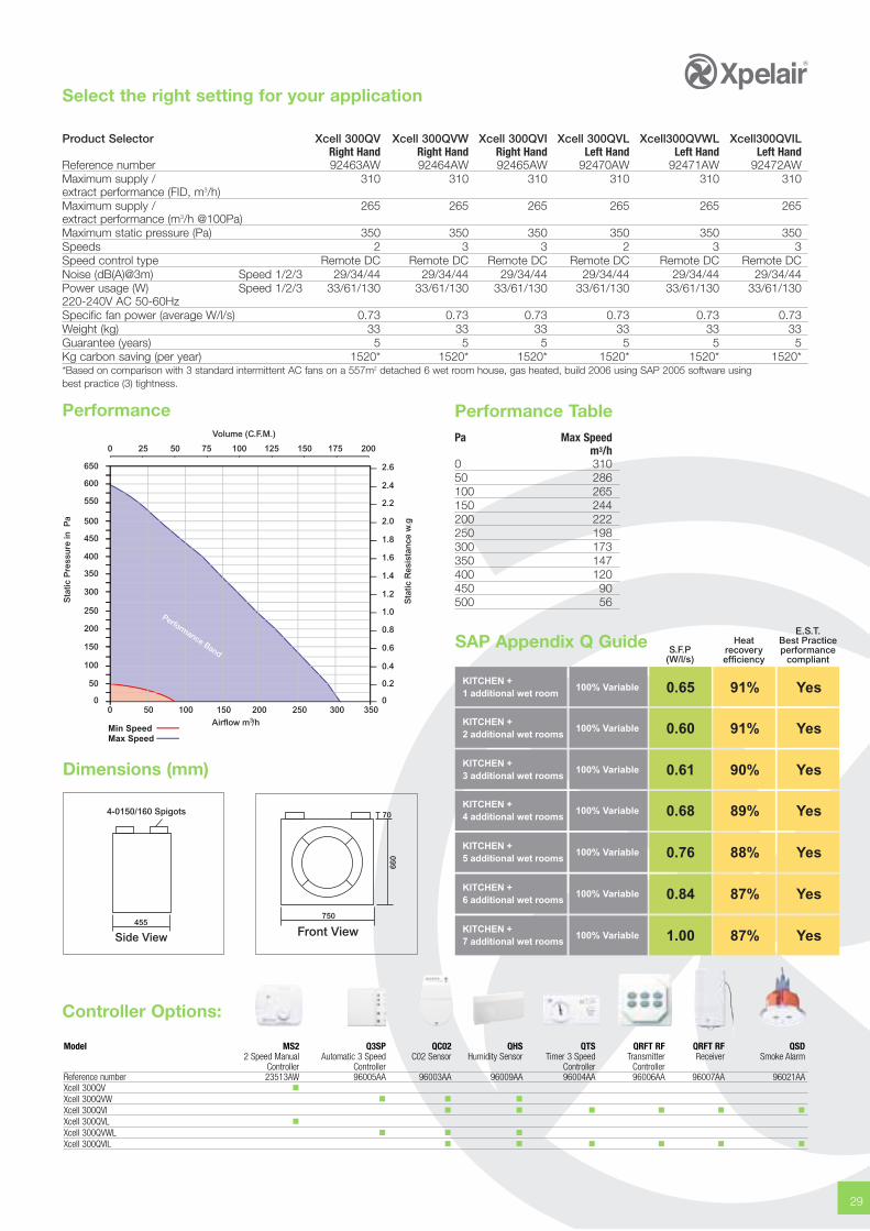
Product Selector Xcell 300QV Xcell 300QVW Xcell 300QVI Xcell 300QVL Xcell300QVWL Xcell300QVILRight Hand Right Hand Right Hand Left Hand Left Hand Left Hand
Reference number 92463AW 92464AW 92465AW 92470AW 92471AW 92472AWMaximum supply / 310 310 310 310 310 310extract performance (FID, m3/h)Maximum supply / 265 265 265 265 265 265extract performance (m3/h @100Pa)Maximum static pressure (Pa) 350 350 350 350 350 350Speeds 2 3 3 2 3 3Speed control type Remote DC Remote DC Remote DC Remote DC Remote DC Remote DCNoise (dB(A)@3m) Speed 1/2/3 29/34/44 29/34/44 29/34/44 29/34/44 29/34/44 29/34/44Power usage (W) Speed 1/2/3 33/61/130 33/61/130 33/61/130 33/61/130 33/61/130 33/61/130220-240V AC 50-60Hz Specific fan power (average W/l/s) 0.73 0.73 0.73 0.73 0.73 0.73Weight (kg) 33 33 33 33 33 33Guarantee (years) 5 5 5 5 5 5Kg carbon saving (per year) 1520* 1520* 1520* 1520* 1520* 1520**Based on comparison with 3 standard intermittent AC fans on a 557m2 detached 6 wet room house, gas heated, build 2006 using SAP 2005 software usingbest practice (3) tightness.
Dimensions (mm)
455750
660
70
Performance TablePa Max Speed
m3/h0 31050 286100 265150 244200 222250 198300 173350 147400 120450 90500 56
Heatrecoveryefficiency
S.F.P(W/l/s)
KITCHEN +1 additional wet room
100% Variable 0.65 91%
KITCHEN +2 additional wet rooms
100% Variable 0.60 91%
KITCHEN +3 additional wet rooms
100% Variable 0.61 90%
KITCHEN +4 additional wet rooms
100% Variable 0.68 89%
E.S.T.Best Practiceperformance
compliant
Yes
Yes
Yes
Yes
KITCHEN +5 additional wet rooms
100% Variable 0.76 88% Yes
KITCHEN +6 additional wet rooms
100% Variable 0.84 87% Yes
KITCHEN +7 additional wet rooms
100% Variable 1.00 87% Yes
SAP Appendix Q Guide
Controller Options:
Model MS2 Q3SP QC02 QHS QTS QRFT RF QRFT RF QSD2 Speed Manual Automatic 3 Speed C02 Sensor Humidity Sensor Timer 3 Speed Transmitter Receiver Smoke Alarm
Controller Controller Controller ControllerReference number 23513AW 96005AA 96003AA 96009AA 96004AA 96006AA 96007AA 96021AAXcell 300QV �Xcell 300QVW � � �Xcell 300QVI � � � � � �Xcell 300QVL �Xcell 300QVWL � � �Xcell 300QVIL � � � � � �
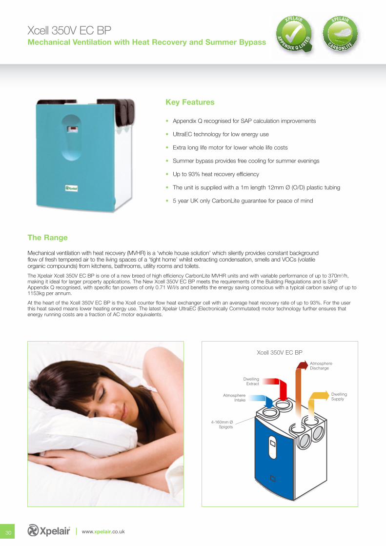
Xcell 350V EC BPMechanical Ventilation with Heat Recovery and Summer Bypass
Mechanical ventilation with heat recovery (MVHR) is a ‘whole house solution’ which silently provides constant backgroundflow of fresh tempered air to the living spaces of a ‘tight home’ whilst extracting condensation, smells and VOCs (volatileorganic compounds) from kitchens, bathrooms, utility rooms and toilets.
The Xpelair Xcell 350V EC BP is one of a new breed of high efficiency CarbonLite MVHR units and with variable performance of up to 370m3/h, making it ideal for larger property applications. The New Xcell 350V EC BP meets the requirements of the Building Regulations and is SAPAppendix Q recognised, with specific fan powers of only 0.71 W/l/s and benefits the energy saving conscious with a typical carbon saving of up to1153kg per annum.
At the heart of the Xcell 350V EC BP is the Xcell counter flow heat exchanger cell with an average heat recovery rate of up to 93%. For the userthis heat saved means lower heating energy use. The latest Xpelair UltraEC (Electronically Commutated) motor technology further ensures thatenergy running costs are a fraction of AC motor equivalents.
Key Features
• Appendix Q recognised for SAP calculation improvements
• UltraEC technology for low energy use
• Extra long life motor for lower whole life costs
• Summer bypass provides free cooling for summer evenings
• Up to 93% heat recovery efficiency
• The unit is supplied with a 1m length 12mm Ø (O/D) plastic tubing
• 5 year UK only CarbonLite guarantee for peace of mind
30 www.xpelair.co.uk
AtmosphereDischarge
DwellingSupply
4-160mm ØSpigots
AtmosphereIntake
DwellingExtract
The Range
Xcell 350V EC BP
Select the right setting for your application
31
Performance
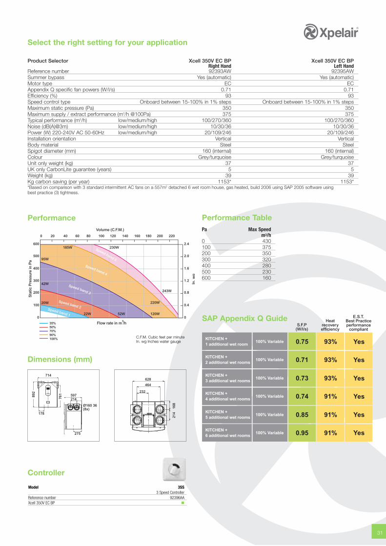
Product Selector Xcell 350V EC BP Xcell 350V EC BPRight Hand Left Hand
Reference number 92393AW 92395AWSummer bypass Yes (automatic) Yes (automatic)Motor type EC ECAppendix Q specific fan powers (W/l/s) 0.71 0.71Efficiency (%) 93 93Speed control type Onboard between 15-100% in 1% steps Onboard between 15-100% in 1% stepsMaximum static pressure (Pa) 350 350Maximum supply / extract performance (m3/h @100Pa) 375 375Typical performance (m3/h) low/medium/high 100/270/360 100/270/360Noise (dB(A)@3m) low/medium/high 10/30/36 10/30/36Power (W) 220-240V AC 50-60Hz low/medium/high 20/109/246 20/109/246Installation orientation Vertical VerticalBody material Steel SteelSpigot diameter (mm) 160 (internal) 160 (internal)Colour Grey/turquoise Grey/turquoiseUnit only weight (kg) 37 37UK only CarbonLite guarantee (years) 5 5 Weight (kg) 39 39Kg carbon saving (per year) 1153* 1153**Based on comparison with 3 standard intermittent AC fans on a 557m2 detached 6 wet room house, gas heated, build 2006 using SAP 2005 software usingbest practice (3) tightness.
Dimensions (mm)
178
714
597214
275
892
761
628
464
232
214
168
Performance TablePa Max Speed
m3/h0 430100 375200 350300 320400 280500 230600 160
Heatrecoveryefficiency
S.F.P(W/l/s)
KITCHEN +1 additional wet room
100% Variable 0.75 93%
KITCHEN +2 additional wet rooms
100% Variable 0.71 93%
KITCHEN +3 additional wet rooms
100% Variable 0.73 93%
KITCHEN +4 additional wet rooms
100% Variable 0.74 91%
KITCHEN +5 additional wet rooms
100% Variable 0.85 91%
KITCHEN +6 additional wet rooms
100% Variable 0.95 91%
E.S.T.Best Practiceperformance
compliant
Yes
Yes
Yes
Yes
Yes
Yes
SAP Appendix Q Guide35%50%70%90%100%
Sta
tic P
ress
ure
in P
a
In. w
g
Volume (C.F.M.)
0 20 40 60 80 100 120 140 160 180 200 220
300
200
100
0
400
500
600
1.2
0.8
0.4
0
1.6
2.0
2.4
Flow rate in m /h3
185W 230W
95W
42W
20W
Speed band 1
Speed band 2
Speed band 3
Speed band 4
Speed band 5
22W 52W 120W
220W
243W
C.F.M. Cubic feet per minuteIn. wg Inches water gauge
Controller
Model 3SS3 Speed Controller
Reference number 92396AAXcell 350V EC BP �
32 www.xpelair.co.uk
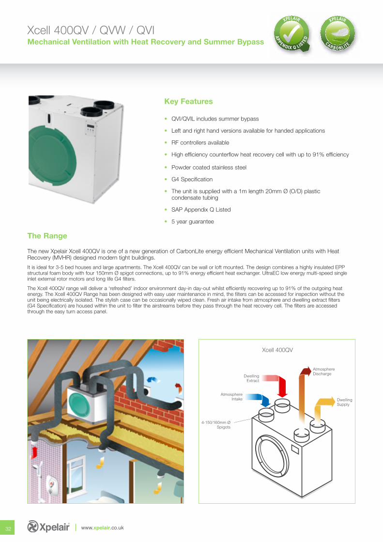
Xcell 400QV / QVW / QVI Mechanical Ventilation with Heat Recovery and Summer Bypass
AtmosphereDischarge
DwellingSupply
DwellingExtract
AtmosphereIntake
4-150/160mm ØSpigots
The new Xpelair Xcell 400QV is one of a new generation of CarbonLite energy efficient Mechanical Ventilation units with HeatRecovery (MVHR) designed modern tight buildings.
It is ideal for 3-5 bed houses and large apartments. The Xcell 400QV can be wall or loft mounted. The design combines a highly insulated EPPstructural foam body with four 150mm Ø spigot connections, up to 91% energy efficient heat exchanger. UltraEC low energy multi-speed singleinlet external rotor motors and long life G4 filters.
The Xcell 400QV range will deliver a ‘refreshed’ indoor environment day-in day-out whilst efficiently recovering up to 91% of the outgoing heat energy. The Xcell 400QV Range has been designed with easy user maintenance in mind, the filters can be accessed for inspection without the unit being electrically isolated. The stylish case can be occasionally wiped clean. Fresh air intake from atmosphere and dwelling extract filters (G4 Specification) are housed within the unit to filter the airstreams before they pass through the heat recovery cell. The filters are accessed through the easy turn access panel.
Key Features
• QVI/QVIL includes summer bypass
• Left and right hand versions available for handed applications
• RF controllers available
• High efficiency counterflow heat recovery cell with up to 91% efficiency
• Powder coated stainless steel
• G4 Specification
• The unit is supplied with a 1m length 20mm Ø (O/D) plastic condensate tubing
• SAP Appendix Q Listed
• 5 year guarantee
The Range
Xcell 400QV
33
Select the right setting for your application
Performance
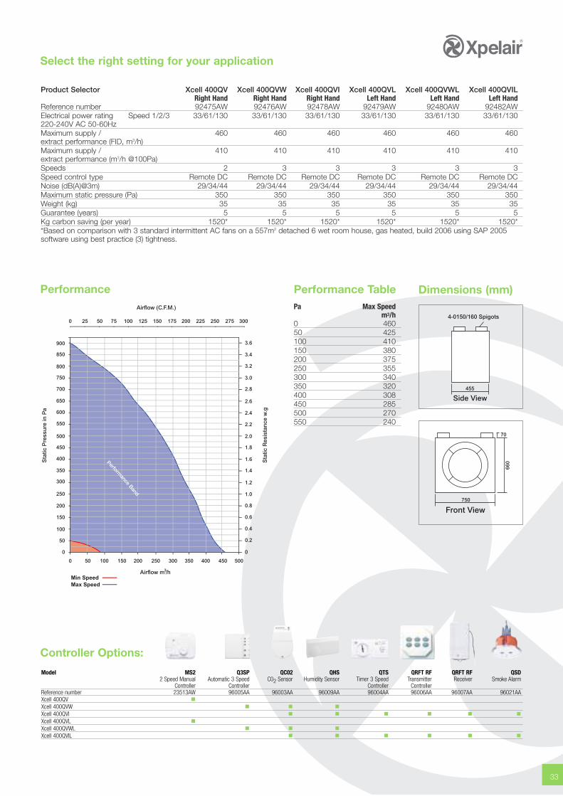
Product Selector Xcell 400QV Xcell 400QVW Xcell 400QVI Xcell 400QVL Xcell 400QVWL Xcell 400QVILRight Hand Right Hand Right Hand Left Hand Left Hand Left Hand
Reference number 92475AW 92476AW 92478AW 92479AW 92480AW 92482AWElectrical power rating Speed 1/2/3 33/61/130 33/61/130 33/61/130 33/61/130 33/61/130 33/61/130220-240V AC 50-60HzMaximum supply / 460 460 460 460 460 460extract performance (FID, m3/h) Maximum supply / 410 410 410 410 410 410extract performance (m3/h @100Pa)Speeds 2 3 3 3 3 3Speed control type Remote DC Remote DC Remote DC Remote DC Remote DC Remote DCNoise (dB(A)@3m) 29/34/44 29/34/44 29/34/44 29/34/44 29/34/44 29/34/44Maximum static pressure (Pa) 350 350 350 350 350 350Weight (kg) 35 35 35 35 35 35 Guarantee (years) 5 5 5 5 5 5Kg carbon saving (per year) 1520* 1520* 1520* 1520* 1520* 1520**Based on comparison with 3 standard intermittent AC fans on a 557m2 detached 6 wet room house, gas heated, build 2006 using SAP 2005software using best practice (3) tightness.
Model MS2 Q3SP QC02 QHS QTS QRFT RF QRFT RF QSD2 Speed Manual Automatic 3 Speed C02 Sensor Humidity Sensor Timer 3 Speed Transmitter Receiver Smoke Alarm
Controller Controller Controller ControllerReference number 23513AW 96005AA 96003AA 96009AA 96004AA 96006AA 96007AA 96021AAXcell 400QV �Xcell 400QVW � � �Xcell 400QVI � � � � � �Xcell 400QVL �Xcell 400QVWL � � �Xcell 400QVIL � � � � � �
455
75066
0
70
Performance TablePa Max Speed
m3/h0 460 50 425 100 410 150 380 200 375 250 355 300 340 350 320 400 308 450 285 500 270 550 240
Dimensions (mm)
Airflow m /h3
Min SpeedMax Speed
Sta
tic P
ress
ure
in P
a
Sta
tic R
esis
tan
ce w
.g
Airflow (C.F.M.)
0 25 50 75 100 125 150 175 200 225 250 275 300
0 50 100 150 200 250 300 350 400 450 500
0
50
100
150
200
250
300
350
400
450
500
550
600
650
700
750
800
850
900
0
0.2
0.4
0.6
0.8
1.0
1.2
1.4
1.6
1.8
2.0
2.2
2.4
2.6
2.8
3.0
3.2
3.4
3.6
Performance Band
Controller Options:
Xcell 150 / 150RHorizontal Hideaway Heat Recovery Unit MVHR
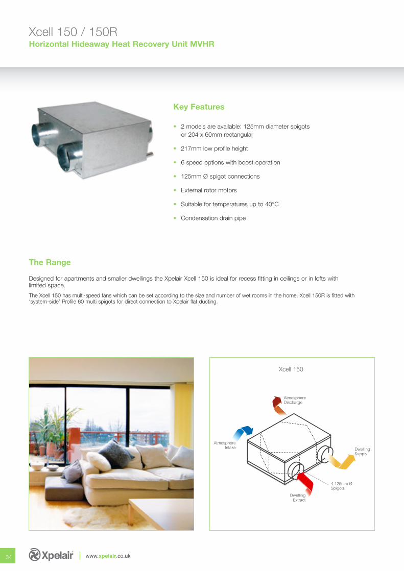
Designed for apartments and smaller dwellings the Xpelair Xcell 150 is ideal for recess fitting in ceilings or in lofts withlimited space.
The Xcell 150 has multi-speed fans which can be set according to the size and number of wet rooms in the home. Xcell 150R is fitted with‘system-side’ Profile 60 multi spigots for direct connection to Xpelair flat ducting.
Key Features
• 2 models are available: 125mm diameter spigotsor 204 x 60mm rectangular
• 217mm low profile height
• 6 speed options with boost operation
• 125mm Ø spigot connections
• External rotor motors
• Suitable for temperatures up to 40°C
• Condensation drain pipe
34
The Range
AtmosphereDischarge
DwellingExtract
DwellingSupply
4-125mm ØSpigots
AtmosphereIntake
www.xpelair.co.uk
Xcell 150
Select the right setting for your application
35
Speed 1Speed 2Speed 3
Speed 4Speed 5Speed 6
Airflow m /h3
0 25 50 75 100 125 150 175 200
Sta
tic P
ress
ure
in P
a
0
25
50
75
100
125
150
175
200
225
250
275
300
Sta
tic R
esis
tan
ce w
.g
0
0.1
0.2
0.3
0.4
0.5
0.6
0.7
0.8
0.9
1.0
1.1
1.2
Airflow (C.F.M.)
0 25 50 75 100 125
Performance Performance Table
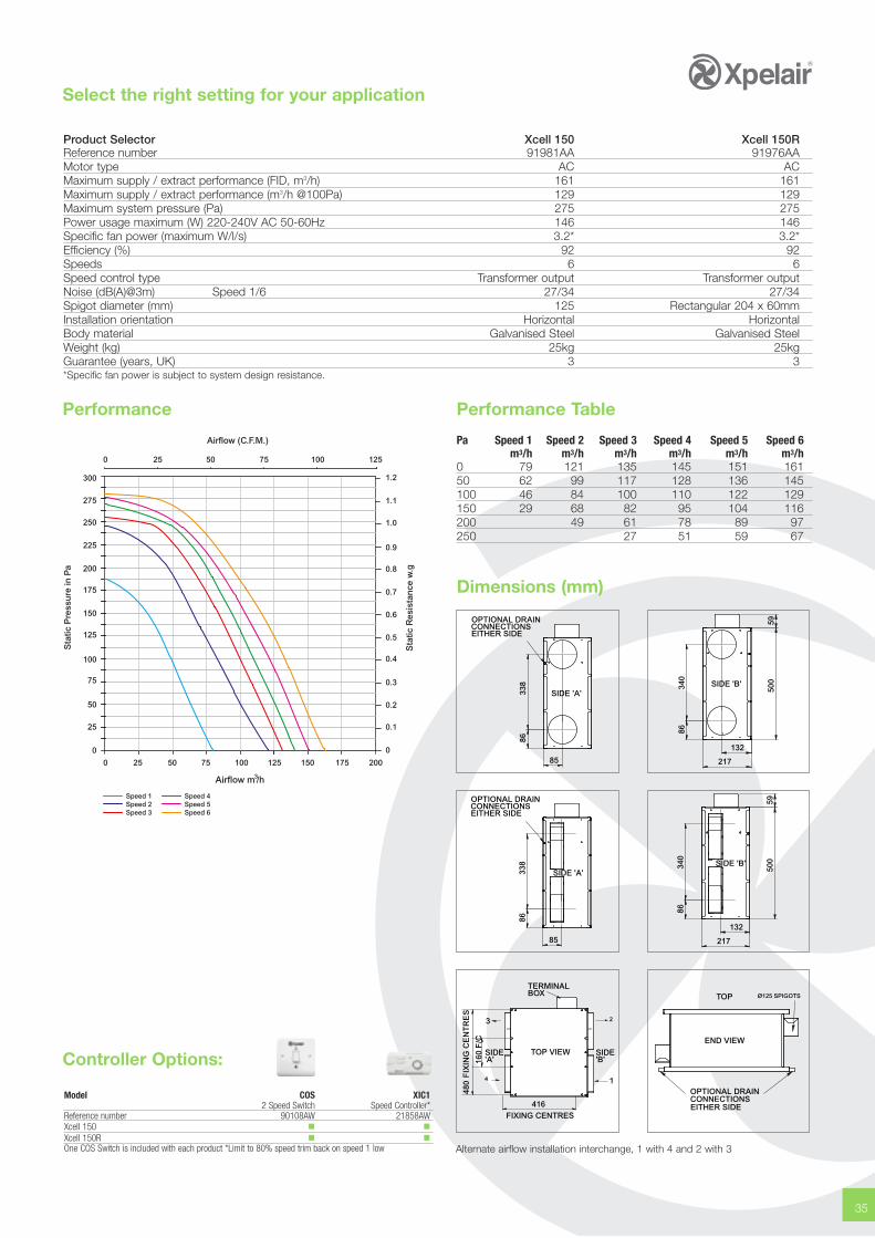
Product Selector Xcell 150 Xcell 150RReference number 91981AA 91976AAMotor type AC ACMaximum supply / extract performance (FID, m3/h) 161 161Maximum supply / extract performance (m3/h @100Pa) 129 129Maximum system pressure (Pa) 275 275Power usage maximum (W) 220-240V AC 50-60Hz 146 146Specific fan power (maximum W/l/s) 3.2* 3.2*Efficiency (%) 92 92Speeds 6 6Speed control type Transformer output Transformer outputNoise (dB(A)@3m) Speed 1/6 27/34 27/34Spigot diameter (mm) 125 Rectangular 204 x 60mmInstallation orientation Horizontal HorizontalBody material Galvanised Steel Galvanised SteelWeight (kg) 25kg 25kgGuarantee (years, UK) 3 3*Specific fan power is subject to system design resistance.
Pa Speed 1 Speed 2 Speed 3 Speed 4 Speed 5 Speed 6m3/h m3/h m3/h m3/h m3/h m3/h
0 79 121 135 145 151 16150 62 99 117 128 136 145100 46 84 100 110 122 129150 29 68 82 95 104 116200 49 61 78 89 97250 27 51 59 67
85
8633
8
SIDE 'A'
OPTIONAL DRAINCONNECTIONSEITHER SIDE
132
217
8634
0
500
59
SIDE 'B'
Dimensions (mm)
85
8633
8
SIDE 'A'
OPTIONAL DRAINCONNECTIONSEITHER SIDE
132
217
8634
0
500
59
SIDE 'B'
23
4
416 FIXING CENTRES
480
FIX
ING
CE
NT
RE
S
160
F/C
SIDE'A'
SIDE'B'
TERMINALBOX
1
TOP VIEW
TOP
END VIEW
Ø125 SPIGOTS
OPTIONAL DRAINCONNECTIONSEITHER SIDE
Controller Options:
Model COS XIC12 Speed Switch Speed Controller*
Reference number 90108AW 21858AWXcell 150 � �Xcell 150R � �One COS Switch is included with each product *Limit to 80% speed trim back on speed 1 low Alternate airflow installation interchange, 1 with 4 and 2 with 3
Xcell 200 / 200R / 200BP / 200RBPHorizontal Hideaway Heat Recovery Unit
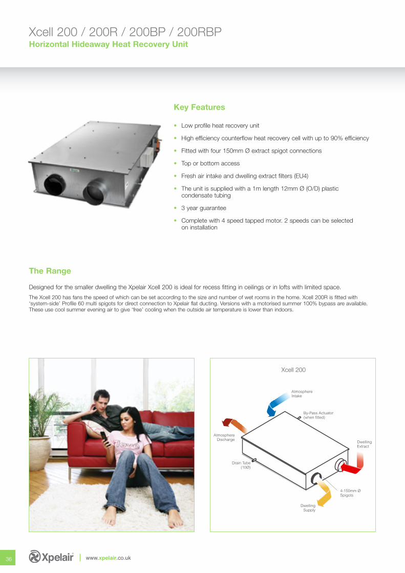
Designed for the smaller dwelling the Xpelair Xcell 200 is ideal for recess fitting in ceilings or in lofts with limited space.
The Xcell 200 has fans the speed of which can be set according to the size and number of wet rooms in the home. Xcell 200R is fitted with‘system-side’ Profile 60 multi spigots for direct connection to Xpelair flat ducting. Versions with a motorised summer 100% bypass are available.These use cool summer evening air to give ‘free’ cooling when the outside air temperature is lower than indoors.
Key Features
• Low profile heat recovery unit
• High efficiency counterflow heat recovery cell with up to 90% efficiency
• Fitted with four 150mm Ø extract spigot connections
• Top or bottom access
• Fresh air intake and dwelling extract filters (EU4)
• The unit is supplied with a 1m length 12mm Ø (O/D) plastic condensate tubing
• 3 year guarantee
• Complete with 4 speed tapped motor. 2 speeds can be selected on installation
36 www.xpelair.co.uk
AtmosphereDischarge
DwellingSupply
AtmosphereIntake
DwellingExtract
4-150mm ØSpigots
Drain Tube(10Ø)
By-Pass Actuator(when fitted)
Xcell 200
The Range
Select the right setting for your application
37
Performance
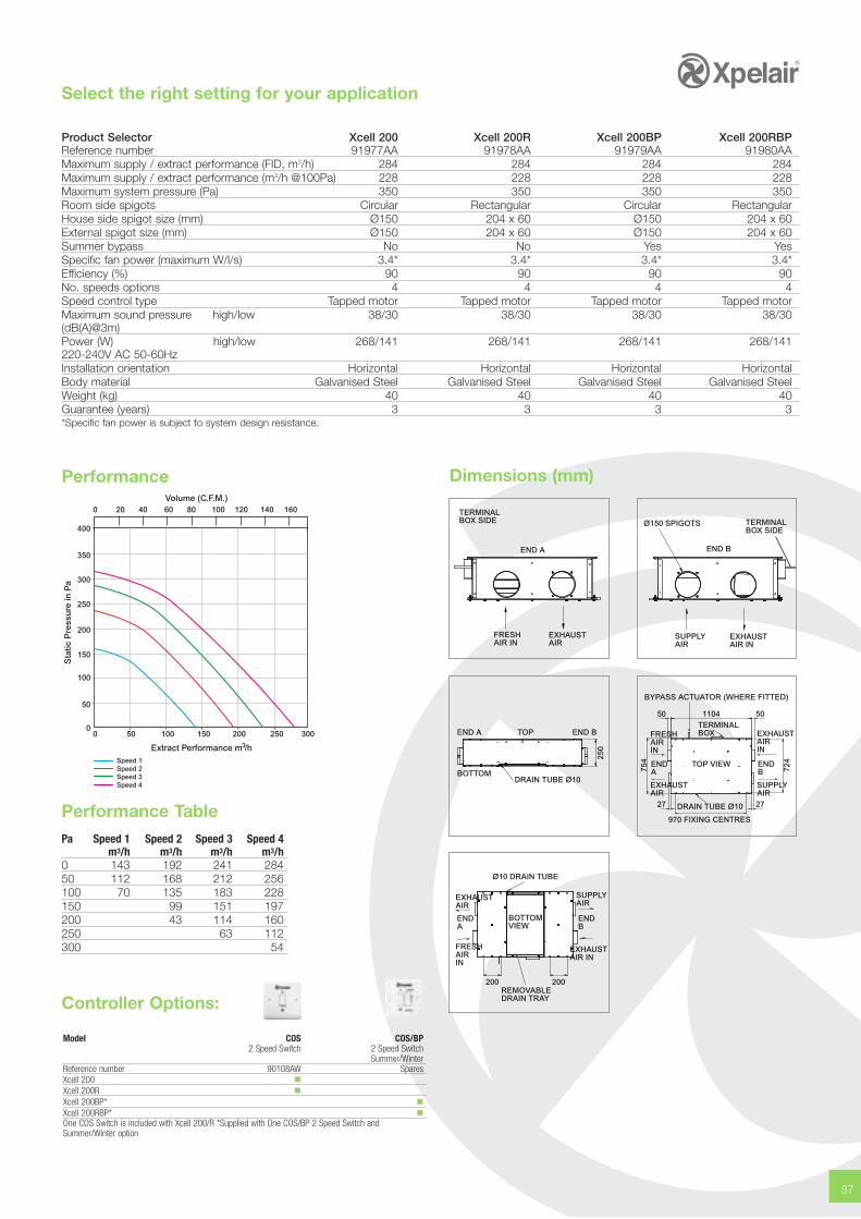
Performance TablePa Speed 1 Speed 2 Speed 3 Speed 4
m3/h m3/h m3/h m3/h0 143 192 241 28450 112 168 212 256100 70 135 183 228150 99 151 197200 43 114 160250 63 112300 54
0 50 100 150 200 250 300
0 20 40 60 80 100 120 140 160
0
50
100
150
200
250
300
350
400
Sta
tic P
ress
ure
in P
a
3Extract Performance m /hSpeed 1Speed 2Speed 3Speed 4
Volume (C.F.M.)
Product Selector Xcell 200 Xcell 200R Xcell 200BP Xcell 200RBPReference number 91977AA 91978AA 91979AA 91980AAMaximum supply / extract performance (FID, m3/h) 284 284 284 284Maximum supply / extract performance (m3/h @100Pa) 228 228 228 228Maximum system pressure (Pa) 350 350 350 350 Room side spigots Circular Rectangular Circular RectangularHouse side spigot size (mm) Ø150 204 x 60 Ø150 204 x 60External spigot size (mm) Ø150 204 x 60 Ø150 204 x 60Summer bypass No No Yes YesSpecific fan power (maximum W/l/s) 3.4* 3.4* 3.4* 3.4*Efficiency (%) 90 90 90 90No. speeds options 4 4 4 4Speed control type Tapped motor Tapped motor Tapped motor Tapped motorMaximum sound pressure high/low 38/30 38/30 38/30 38/30(dB(A)@3m)Power (W) high/low 268/141 268/141 268/141 268/141220-240V AC 50-60HzInstallation orientation Horizontal Horizontal Horizontal HorizontalBody material Galvanised Steel Galvanised Steel Galvanised Steel Galvanised SteelWeight (kg) 40 40 40 40Guarantee (years) 3 3 3 3*Specific fan power is subject to system design resistance.
TERMINALBOX SIDE
END A
FRESHAIR IN
EXHAUSTAIR
SUPPLYAIR
EXHAUSTAIR IN
Ø150 SPIGOTS
END B
TERMINALBOX SIDE
Dimensions (mm)
END A
BOTTOM
END BTOP
250
DRAIN TUBE Ø10
110450 50
27 27
BYPASS ACTUATOR (WHERE FITTED)
TERMINALBOXFRESH
AIRIN
EXHAUSTAIR
SUPPLYAIR
EXHAUSTAIRIN
754
724END
ATOP VIEW
DRAIN TUBE Ø10
970 FIXING CENTRES
ENDB
Ø10 DRAIN TUBE
BOTTOMVIEW
ENDA
EXHAUSTAIR
FRESHAIRIN
SUPPLYAIR
EXHAUSTAIR IN
ENDB
200 200REMOVABLEDRAIN TRAYController Options:
Model COS COS/BP2 Speed Switch 2 Speed Switch
Summer/WinterReference number 90108AW SparesXcell 200 �Xcell 200R �Xcell 200BP* �Xcell 200RBP* �One COS Switch is included with Xcell 200/R *Supplied with One COS/BP 2 Speed Switch andSummer/Winter option
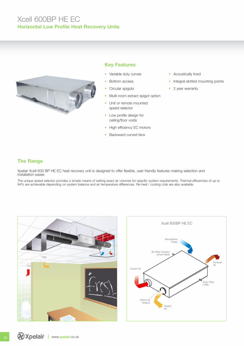
Xcell 600BP HE ECHorizontal Low Profile Heat Recovery Units
38 www.xpelair.co.uk
Key Features
• Variable duty curves
• Bottom access
• Circular spigots
• Multi-room extract spigot option
• Unit or remote mountedspeed selector
• Low profile design forceiling/floor voids
• High efficiency EC motors
• Backward curved fans
• Acoustically lined
• Integral slotted mounting points
• 2 year warranty
Extract Air
SupplyAir
AtmosphereIntake
ExhaustAir
200mm ØSpigots
Drain Tube(10Ø)
By-Pass Actuator(when fitted)
Xpelair Xcell 600 BP HE EC heat recovery unit is designed to offer flexible, user friendly features making selection andinstallation easier.
The unique speed selector provides a simple means of setting exact air volumes for specific system requirements. Thermal efficiencies of up to94% are achievable depending on system balance and air temperature differences. Re-heat / cooling coils are also available.
The Range
Xcell 600BP HE EC
Select the right setting for your application
39
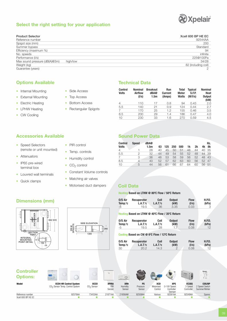
Product Selector Xcell 600 BP HE ECReference number 92544AASpigot size (mm) 200Summer bypass StandardEfficiency (maximum %) 94No. speeds infinitePerformance (l/s) 225@100PaMax sound pressure (dB(A)@3m) high/low 34/28Weight (kg) 82 (including coil)Guarantee (years) 2
Options Available
• Internal Mounting
• External Mounting
• Electric Heating
• LPHW Heating
• CW Cooling
• Side Access
• Top Access
• Bottom Access
• Rectangular Spigots
Sound Power Data
Dimensions (mm)
• Speed Selectors(remote or unit mounted)
• Attenuators
• IP65 pre-wiredterminal box
• Louvred wall terminals
• Quick clamps
• PIR control
• Temp. controls
• Humidity control
• CO2 control
• Constant Volume controls
• Matching air valves
• Motorised duct dampers
Technical DataControl Nominal Breakout Run Total Typical NominalVolts Airflow dBA@ Current Motor S.F.P. Heat
(l/s) 1.5m (Amps) Watts (W/l/s) Output(kW)
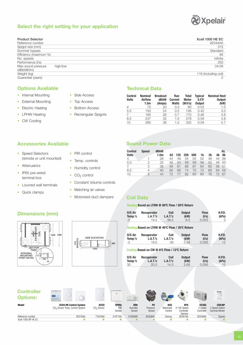
4 110 17 0.8 94 0.43 2.05.5 140 21 0.9 124 0.44 2.77 170 25 1.2 155 0.46 3.58.5 200 29 1.4 186 0.47 4.010 230 33 1.6 270 0.59 4.5
Accessories AvailableControl Speed dBA@ Hz.Volts 1.5m 63 125 250 500 1k 2k 4k 8k4 1 28 40 45 50 51 48 44 40 355.5 2 32 44 49 54 55 52 48 44 397 3 36 48 53 58 59 56 52 48 438.5 4 40 52 57 62 63 60 56 52 4710 5 44 56 61 66 67 64 60 56 51
Coil DataHeating Based on LTHW @ 80OC Flow / 50OC Return
O/S Air Recuperator Coil Output Flow H.P.D.Temp.Oc L.A.T.Oc L.A.T.Oc (kW) (l/s) (kPa)-5 19.5 36 3.35 0.03 3
Heating Based on LTHW @ 40OC Flow / 35OC Return
O/S Air Recuperator Coil Output Flow H.P.D.Temp.Oc L.A.T.Oc L.A.T.Oc (kW) (l/s) (kPa)-5 19.5 28 1.7 0.08 12
Cooling Based on CW @ 6OC Flow / 12OC Return
O/S Air Recuperator Coil Output Flow H.P.D.Temp.Oc L.A.T.Oc L.A.T.Oc (kW) (l/s) (kPa)30 20.2 14.3 2 0.08 12
950 1015
15017.5
INTEGRALMOUNTING
POINT DETAIL
SECTIONTHRO’
CO
IL
HE
AT
EX
CH
AN
GE
R
380
SIDE ELEVATION
200
øS
PIG
OT
S
1300
Model ECO4 HR Control System XCCO XPIRA XRH PS XCD XPS EC3SS COS/BPCO2 Sensor Temp. Control System CO2 Sensor PIR Humidity Pressure Motorised 0-10V Speed 3 Speed 2 Speed Switch
Sensor Sensor Sensor Control Controller Controller Summer/WinterDamper
Reference number 92578AA 73433AA 21871AA 21856AW 92508AA Various 92581AA 92549AA SparesXcell 600 BP HE EC � � � � � � � � �
ControllerOptions:
Xcell 600BP HE ECHorizontal Low Profile Heat Recovery Units
40 www.xpelair.co.uk
450
400
350
300
250
200
150
100
50
0
Pa.
0 50 100 150 200 250
l/s
0 180 300 540 720 900
m3/hr
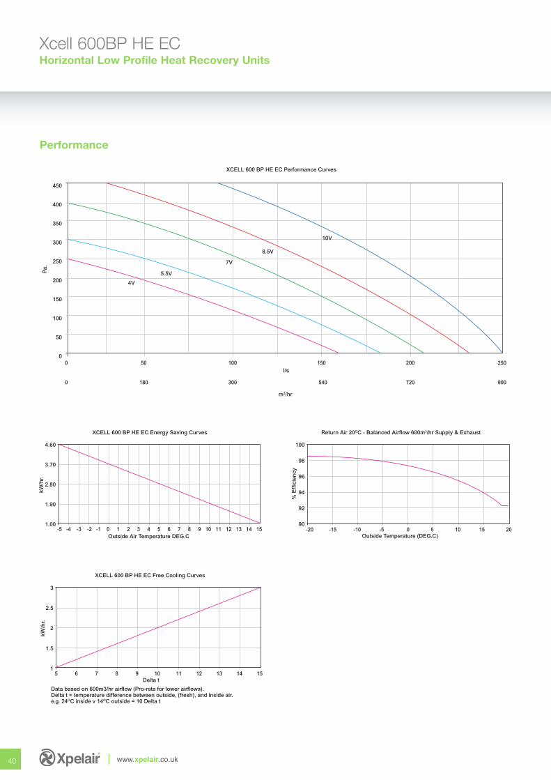
XCELL 600 BP HE EC Performance Curves
4V
5.5V
7V
8.5V
10V
Performance
4.60
3.70
2.80
1.90
1.00
kW/h
r.
-5 -4 -3 -2 -1 0 1 2 3 4 5 6 7 8 9 10 11 12 13 14 15
Outside Air Temperature DEG.C
XCELL 600 BP HE EC Energy Saving Curves
3
2.5
2
1.5
1
kW/h
r.
5 6 7 8 9 10 11 12 13 14 15
Delta t
Data based on 600m3/hr airflow (Pro-rata for lower airflows).Delta t = temperature difference between outside, (fresh), and inside air.e.g. 24OC inside v 14OC outside = 10 Delta t
XCELL 600 BP HE EC Free Cooling Curves
100
98
96
94
92
90
% E
ffici
ency
-20 -15 -10 -5 0 5 10 15 20
Outside Temperature (DEG.C)
Return Air 20OC - Balanced Airflow 600m3/hr Supply & Exhaust
41
Specification
Casings
Unit casings shall be manufactured from best quality galvanisedsheet steel with access from top or bottom. Reinforced slottedsafety fixing points shall be incorporated to facilitate drop-rodsor mounting bolts within overall unit width. All permanent fixingsshall be riveted and all removable items shall be retained viasetscrews and nutserts. Fan mounting plate shall incorporate‘damped panel’ technology and shall be easily removable viaaccess panel.
Insulation
Optional insulation shall be CFC and HFC-free, class ‘O’ opencell expanded foam, for thermal and acoustic purposes, with amaximum thermal conductivity of 0.035 w/m2k, fully incompliance with London Borough and CAA airport authorityflammability and toxicity requirements. Adhesive is a light andageing resistant modified acrylic synthetic resin with hightemperature tolerance.
Fans
Fans shall be single-inlet, single width, direct drive centrifugaltype with high efficiency, low noise, backward-curved impellers.Motor/impeller assemblies shall be statically and dynamicallybalanced, in two planes, in accordance with BS 5265, Part 1,1979 to G2.5. Fans shall be mounted individually onto fandecks to facilitate easy removal.
Motors
Motors shall be totally enclosed, high-efficiency, EC, externalrotor type with power factors of better than 0.9. Max. ambientoperating temp. 50°C. Bearings shall be sealed-for-life,maintenance-free, ball bearing type with a minimum lifeexpectancy of 100,000 hours under design operatingconditions. Insulation shall be to Class ‘B’ with enclosure toIP44. Electrical supply shall be 220/240V 1ph. 50Hz.
Recuperators (heat recovery cell)
Recuperators shall be manufactured from 100% re-cyclableplastic and offer temperature efficiencies up to 94% dependingon thermal / humidity conditions and balanced airflow. Summerbypass facility shall be fitted as standard.
Speed Selectors
Speed control shall by means of 0-10V input giving infinitespeed control allowing accurate adjustment to suitsite conditions.
Optional Terminal Boxes
Electrical connections can be wired via an external terminalbox, with removable cover, in accordance with currentwiring regulations.
Note: Refer to the installation manual for wiring diagrams.
Filters
Filters shall be EU2/3 to Eurovent 4/5. Media shall beextended surface area, continuous filament with F1 fireresistance to DIN 53438, dust holding capacity of 400 g/m2,shall be supported by an integral wire frame and shall havedisposable/washable options. Withdrawal shall be viaremovable bottom access panel.
Heaters & Coils
Electric heaters shall be open coil, low inertia type fitted withauto-resetting thermal overloads for higher efficiency andgreater safety. Outputs from 0.5kW to 6.0kW shall be availableon single phase supply operating from on/off, stepped orthyristor controls. (Full control panels are available for unit orremote mounting to specification). Heating & cooling coils shallbe 10mm dia. copper tube expanded into aluminium fins formaximum heat transfer.
Xcell 600 / 600BPHorizontal Hideaway Heat Recovery Unit
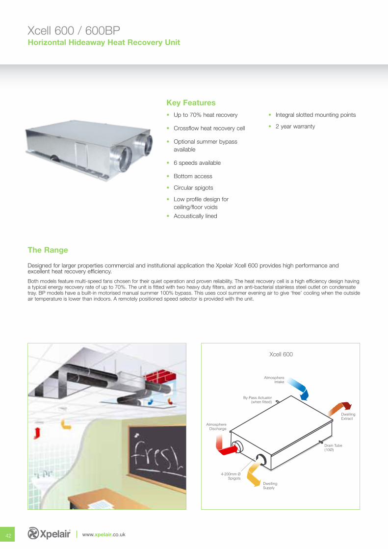
Designed for larger properties commercial and institutional application the Xpelair Xcell 600 provides high performance andexcellent heat recovery efficiency.
Both models feature multi-speed fans chosen for their quiet operation and proven reliability. The heat recovery cell is a high efficiency design havinga typical energy recovery rate of up to 70%. The unit is fitted with two heavy duty filters, and an anti-bacterial stainless steel outlet on condensatetray. BP models have a built-in motorised manual summer 100% bypass. This uses cool summer evening air to give ‘free’ cooling when the outsideair temperature is lower than indoors. A remotely positioned speed selector is provided with the unit.
42 www.xpelair.co.uk
AtmosphereDischarge
DwellingSupply
AtmosphereIntake
DwellingExtract
4-200mm ØSpigots
Drain Tube(10Ø)
By-Pass Actuator(when fitted)
The Range
Key Features• Up to 70% heat recovery
• Crossflow heat recovery cell
• Optional summer bypass available
• 6 speeds available
• Bottom access
• Circular spigots
• Low profile design forceiling/floor voids
• Acoustically lined
• Integral slotted mounting points
• 2 year warranty
Xcell 600
Select the right setting for your application
43
Performance
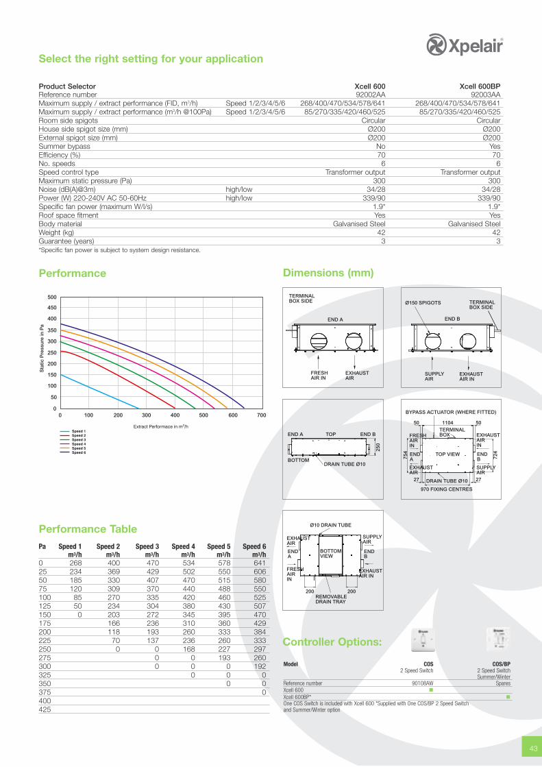
Product Selector Xcell 600 Xcell 600BPReference number 92002AA 92003AAMaximum supply / extract performance (FID, m3/h) Speed 1/2/3/4/5/6 268/400/470/534/578/641 268/400/470/534/578/641Maximum supply / extract performance (m3/h @100Pa) Speed 1/2/3/4/5/6 85/270/335/420/460/525 85/270/335/420/460/525Room side spigots Circular CircularHouse side spigot size (mm) Ø200 Ø200External spigot size (mm) Ø200 Ø200Summer bypass No YesEfficiency (%) 70 70No. speeds 6 6Speed control type Transformer output Transformer outputMaximum static pressure (Pa) 300 300Noise (dB(A)@3m) high/low 34/28 34/28Power (W) 220-240V AC 50-60Hz high/low 339/90 339/90Specific fan power (maximum W/l/s) 1.9* 1.9*Roof space fitment Yes YesBody material Galvanised Steel Galvanised SteelWeight (kg) 42 42Guarantee (years) 3 3*Specific fan power is subject to system design resistance.
Speed 1Speed 2Speed 3Speed 4Speed 5Speed 6
0 100 200 300 400 500 600 7000
50
100
150
200
250
300
350
400
450
500
Sta
tic P
ress
ure
in P
a
TERMINALBOX SIDE
END A
FRESHAIR IN
EXHAUSTAIR
SUPPLYAIR
EXHAUSTAIR IN
Ø150 SPIGOTS
END B
TERMINALBOX SIDE
Dimensions (mm)
END A
BOTTOM
END BTOP
250
DRAIN TUBE Ø10
110450 50
27 27
BYPASS ACTUATOR (WHERE FITTED)
TERMINALBOXFRESH
AIRIN
EXHAUSTAIR
SUPPLYAIR
EXHAUSTAIRIN
754
724END
ATOP VIEW
DRAIN TUBE Ø10
970 FIXING CENTRES
ENDB
Ø10 DRAIN TUBE
BOTTOMVIEW
ENDA
EXHAUSTAIR
FRESHAIRIN
SUPPLYAIR
EXHAUSTAIR IN
ENDB
200 200REMOVABLEDRAIN TRAY
Controller Options:
Model COS COS/BP2 Speed Switch 2 Speed Switch
Summer/WinterReference number 90108AW SparesXcell 600 �Xcell 600BP* �One COS Switch is included with Xcell 600 *Supplied with One COS/BP 2 Speed Switchand Summer/Winter option
Performance TablePa Speed 1 Speed 2 Speed 3 Speed 4 Speed 5 Speed 6
m3/h m3/h m3/h m3/h m3/h m3/h0 268 400 470 534 578 64125 234 369 429 502 550 60650 185 330 407 470 515 58075 120 309 370 440 488 550100 85 270 335 420 460 525125 50 234 304 380 430 507150 0 203 272 345 395 470175 166 236 310 360 429200 118 193 260 333 384225 70 137 236 260 333250 0 0 168 227 297275 0 0 193 260300 0 0 0 192325 0 0 0350 0 0375 0400425
44 www.xpelair.co.uk
Xcell 1000 BP HE ECHorizontal Low Profile Heat Recovery High Efficiency Units
Extract Air
SupplyAir
AtmosphereIntake
ExhaustAir
315mm ØSpigots
Drain Tube(10Ø)
By-Pass Actuator(when fitted)
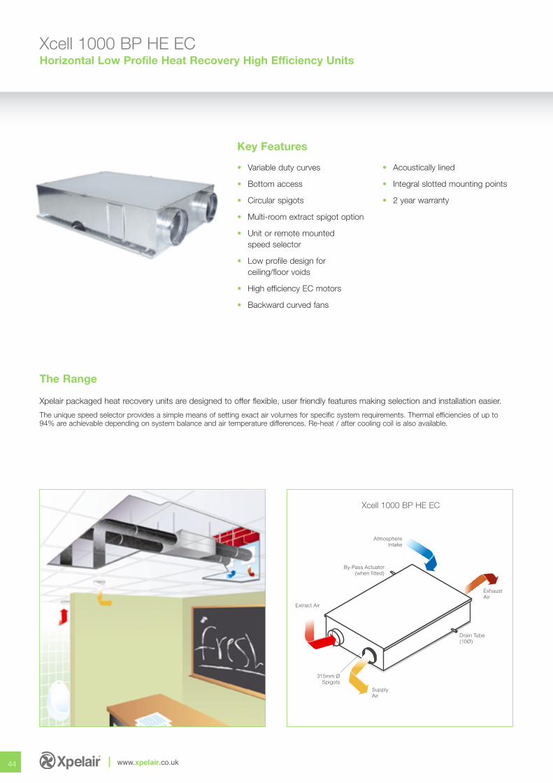
Xpelair packaged heat recovery units are designed to offer flexible, user friendly features making selection and installation easier.
The unique speed selector provides a simple means of setting exact air volumes for specific system requirements. Thermal efficiencies of up to94% are achievable depending on system balance and air temperature differences. Re-heat / after cooling coil is also available.
The Range
Key Features
• Variable duty curves
• Bottom access
• Circular spigots
• Multi-room extract spigot option
• Unit or remote mountedspeed selector
• Low profile design forceiling/floor voids
• High efficiency EC motors
• Backward curved fans
• Acoustically lined
• Integral slotted mounting points
• 2 year warranty
Xcell 1000 BP HE EC
45
Select the right setting for your application
Sound Power Data
Dimensions (mm)
1200 1265
15017.5
INTEGRALMOUNTING
POINT DETAIL
SECTIONTHRO’
CO
IL
HE
AT
EX
CH
AN
GE
R
380
SIDE ELEVATION
315
SP
IGO
TS
1500
Technical DataControl Nominal Breakout Run Total Typical Nominal Heat Volts Airflow dBA@ Current Motor S.F.P. Output
1.5m (Amps) Watts (W/l/s) Output (kW)4 75 20 0.3 80 0.53 1.55.5 150 24 0.5 126 0.42 3.07 185 28 0.7 170 0.46 3.88.5 237 32 1.0 278 0.59 4.810 280 36 1.2 332 0.59 5.7
Control Speed dBA@ Hz.Volts 1.5m 63 125 250 500 1k 2k 4k 8k4 1 28 44 49 54 55 52 48 44 395.5 2 32 48 53 58 59 56 52 48 437 3 36 48 61 66 67 64 60 56 518.5 4 40 56 69 74 75 72 68 64 5910 5 44 72 77 82 83 80 76 72 67
Coil DataHeating Based on LTHW @ 80OC Flow / 50OC Return
O/S Air Recuperator Coil Output Flow H.P.D.Temp.Oc L.A.T.Oc L.A.T.Oc (kW) (l/s) (kPa)-5 19.5 38.5 6.5 0.053 3
Heating Based on LTHW @ 40OC Flow / 35OC Return
O/S Air Recuperator Coil Output Flow H.P.D.Temp.Oc L.A.T.Oc L.A.T.Oc (kW) (l/s) (kPa)-5 19.5 26 2.34 0.056 12
Cooling Based on CW @ 6OC Flow / 12OC Return
O/S Air Recuperator Coil Output Flow H.P.D.Temp.Oc L.A.T.Oc L.A.T.Oc (kW) (l/s) (kPa)30 20.2 14.3 2.65 0.056 12
Product Selector Xcell 1000 HE ECReference number 92544AASpigot size (mm) 315Summer bypass StandardEfficiency (maximum %) 94No. speeds infinitePerformance (l/s) 250Max sound pressure high/low 34/28(dB(A)@3m) Weight (kg) 118 (including coil)Guarantee (years) 2
Options Available• Internal Mounting
• External Mounting
• Electric Heating
• LPHW Heating
• CW Cooling
• Side Access
• Top Access
• Bottom Access
• Rectangular Spigots
• Speed Selectors(remote or unit mounted)
• Attenuators
• IP65 pre-wiredterminal box
• Louvred wall terminals
• Quick clamps
• PIR control
• Temp. controls
• Humidity control
• CO2 control
• Constant Volume controls
• Matching air valves
• Motorised duct dampers
Accessories Available
Model ECO4 HR Control System XCCO XPIRA XRH PS XCD XPS EC3SS COS/BPCO2 Sensor Temp. Control System CO2 Sensor PIR Humidity Pressure Motorised 0-10V Speed 3 Speed 2 Speed Switch
Sensor Sensor Sensor Control Controller Controller Summer/WinterDamper
Reference number 92578AA 73433AA 21871AA 21856AW 92508AA Various 92581AA 92549AA SparesXcell 1000 BP HE EC � � � � � � � � �
ControllerOptions:
46 www.xpelair.co.uk
Xcell 1000 BP HE ECHorizontal Low Profile Heat Recovery High Efficiency Units
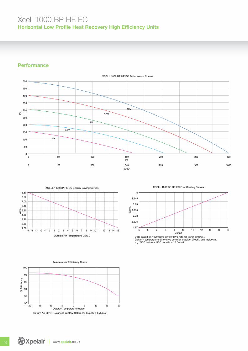
Performance
8.80
7.90
7.00
6.10
5.20
4.30
3.40
2.50
1.60
kW/h
r.
-5 -4 -3 -2 -1 0 1 2 3 4 5 6 7 8 9 10 11 12 13 14 15
Outside Air Temperature DEG.C
XCELL 1000 BP HE EC Energy Saving Curves
5
4.445
3.89
3.335
2.78
2.225
1.67
kW/h
r.
5 6 7 8 9 10 11 12 13 14 15
Delta t
Data based on 1000m3/hr airflow (Pro-rata for lower airflows).Delta t = temperature difference between outside, (fresh), and inside air.e.g. 24OC inside v 14OC outside = 10 Delta t
XCELL 1000 BP HE EC Free Cooling Curves
100
98
96
94
92
90
% E
ffici
ency
-20 -15 -10 -5 0 5 10 15 20
Outside Temperature (deg.c)
Temperature Efficiency Curve
Return Air 20OC - Balanced Airflow 1000m3/hr Supply & Exhaust
500
450
400
350
300
250
200
150
100
50
0
Pa.
0 50 100 150 200 250 300
l/s
0 180 300 540 720 900 1080
m3/hr
XCELL 1000 BP HE EC Performance Curves
4V
5.5V
7V
8.5V
10V
47
Specification
Casings
Unit casings shall be manufactured from best quality galvanisedsheet steel with access from top or bottom. Reinforced slottedsafety fixing points shall be incorporated to facilitate drop-rodsor mounting bolts within overall unit width. All permanent fixingsshall be riveted and all removable items shall be retained viasetscrews and nutserts. Fan mounting plate shall incorporate‘damped panel’ technology and shall be easily removable viaaccess panel.
Insulation
Optional insulation shall be CFC and HFC-free, class ‘O’ opencell expanded foam, for thermal and acoustic purposes, with amaximum thermal conductivity of 0.035 w/m2k, fully incompliance with London Borough and CAA airport authorityflammability and toxicity requirements. Adhesive is a light andageing resistant modified acrylic synthetic resin with hightemperature tolerance.
Fans
Fans shall be single-inlet, single width, direct drive centrifugaltype with high efficiency, low noise, backward-curved impellers.Motor/impeller assemblies shall be statically and dynamicallybalanced, in two planes, in accordance with BS 5265, Part 1,1979 to G2.5. Fans shall be mounted individually onto fandecks to facilitate easy removal.
Motors
Motors shall be totally enclosed, high-efficiency, EC, externalrotor type with power factors of better than 0.9. Max. ambientoperating temp. 50°C. Bearings shall be sealed-for-life,maintenance-free, ball bearing type with a minimum lifeexpectancy of 100,000 hours under design operatingconditions. Insulation shall be to Class ‘B’ with enclosure toIP44. Electrical supply shall be 220/240V 1ph. 50Hz.
Recuperators (heat recovery cell)
Recuperators shall be manufactured from 100% re-cyclableplastic and offer temperature efficiencies up to 94% dependingon thermal / humidity conditions and balanced airflow. Summerbypass facility shall be fitted as standard.
Speed Selectors
Speed control shall by means of 0-10V input giving infinitespeed control allowing accurate adjustment to suitsite conditions.
Optional Terminal Boxes
Electrical connections can be wired via an external terminalbox, with removable cover, in accordance with currentwiring regulations.
Note: Refer to the installation manual for wiring diagrams.
Filters
Filters shall be EU2/3 to Eurovent 4/5. Media shall be extendedsurface area, continuous filament with F1 fire resistance to DIN53438, dust holding capacity of 400 g/m2, shall be supportedby an integral wire frame and shall have disposable/washableoptions. Withdrawal shall be via removable bottomaccess panel.
Heaters & Coils
Electric heaters shall be open coil, low inertia type fitted withauto-resetting thermal overloads for higher efficiency andgreater safety. Outputs from 0.5kW to 6.0kW shall be availableon single phase supply operating from on/off, stepped orthyristor controls. (Full control panels are available for unit orremote mounting to specification). Heating & cooling coils shallbe 10mm dia. copper tube expanded into aluminium fins formaximum heat transfer.
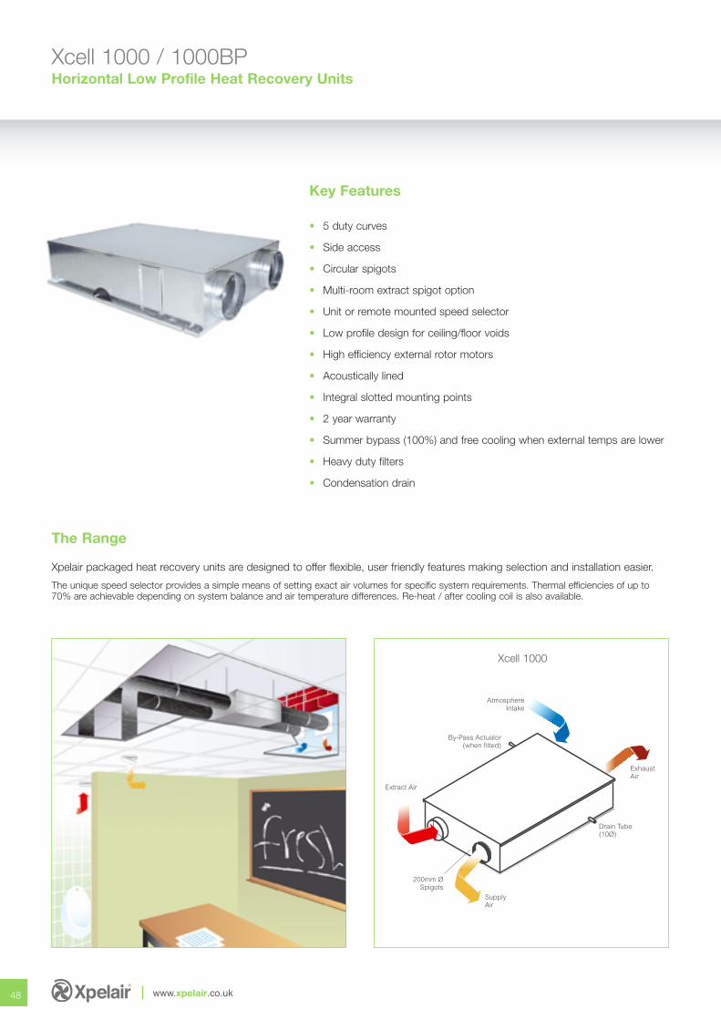
48 www.xpelair.co.uk
Xcell 1000 / 1000BPHorizontal Low Profile Heat Recovery Units
Xpelair packaged heat recovery units are designed to offer flexible, user friendly features making selection and installation easier.
The unique speed selector provides a simple means of setting exact air volumes for specific system requirements. Thermal efficiencies of up to70% are achievable depending on system balance and air temperature differences. Re-heat / after cooling coil is also available.
Key Features
• 5 duty curves
• Side access
• Circular spigots
• Multi-room extract spigot option
• Unit or remote mounted speed selector
• Low profile design for ceiling/floor voids
• High efficiency external rotor motors
• Acoustically lined
• Integral slotted mounting points
• 2 year warranty
• Summer bypass (100%) and free cooling when external temps are lower
• Heavy duty filters
• Condensation drain
The Range
Extract Air
SupplyAir
AtmosphereIntake
ExhaustAir
200mm ØSpigots
Drain Tube(10Ø)
By-Pass Actuator(when fitted)
Xcell 1000
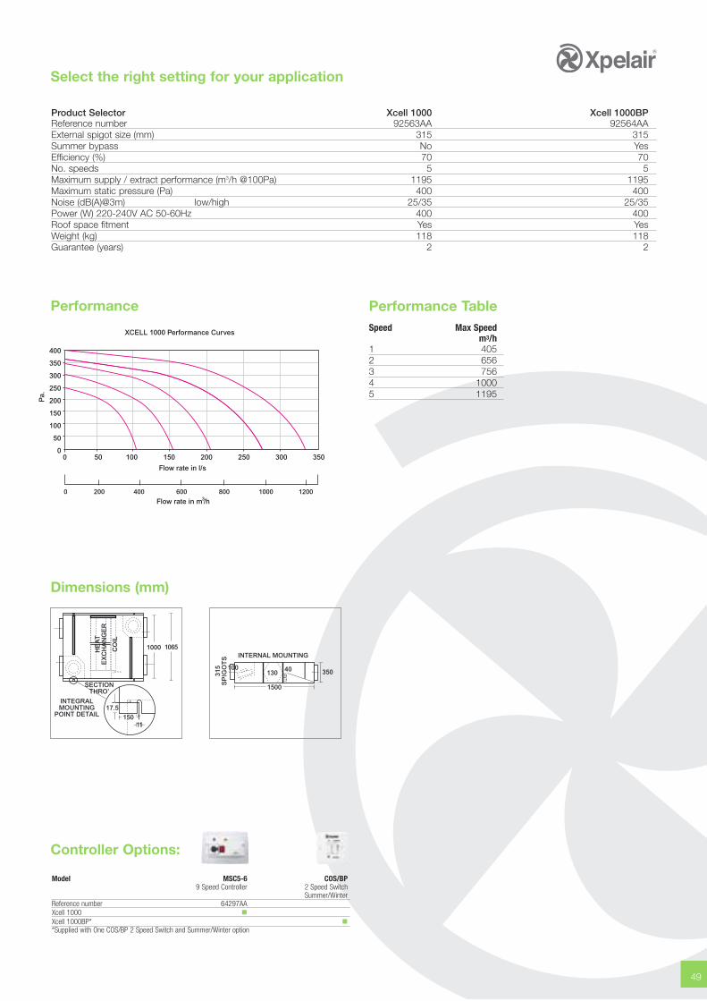
49
Select the right setting for your application
Dimensions (mm)
1000 1065
15017.5
INTEGRALMOUNTING
POINT DETAIL
SECTIONTHRO’
CO
IL
HE
AT
EX
CH
AN
GE
R
350
INTERNAL MOUNTING
315
SP
IGO
TS
1500
100130 40
Product Selector Xcell 1000 Xcell 1000BPReference number 92563AA 92564AAExternal spigot size (mm) 315 315Summer bypass No YesEfficiency (%) 70 70No. speeds 5 5Maximum supply / extract performance (m3/h @100Pa) 1195 1195Maximum static pressure (Pa) 400 400Noise (dB(A)@3m) low/high 25/35 25/35Power (W) 220-240V AC 50-60Hz 400 400Roof space fitment Yes YesWeight (kg) 118 118Guarantee (years) 2 2
400
350
300
250
200
150
100
50
0
Pa.
0 50 100 150 200 250 300 350
XCELL 1000 Performance Curves
0 400200 800 1000 1200600
Flow rate in l/s
Flow rate in m /h3
Performance Performance TableSpeed Max Speed
m3/h1 405 2 656 3 756 4 1000 5 1195
Controller Options:
Model MSC5-6 COS/BP9 Speed Controller 2 Speed Switch
Summer/WinterReference number 64297AAXcell 1000 �Xcell 1000BP* �*Supplied with One COS/BP 2 Speed Switch and Summer/Winter option
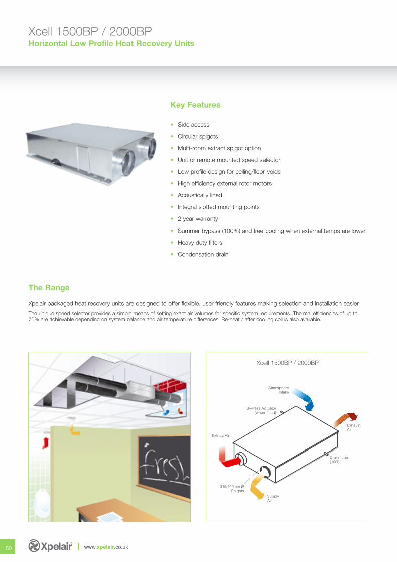
50 www.xpelair.co.uk
Xcell 1500BP / 2000BPHorizontal Low Profile Heat Recovery Units
Xpelair packaged heat recovery units are designed to offer flexible, user friendly features making selection and installation easier.
The unique speed selector provides a simple means of setting exact air volumes for specific system requirements. Thermal efficiencies of up to70% are achievable depending on system balance and air temperature differences. Re-heat / after cooling coil is also available.
Key Features
• Side access
• Circular spigots
• Multi-room extract spigot option
• Unit or remote mounted speed selector
• Low profile design for ceiling/floor voids
• High efficiency external rotor motors
• Acoustically lined
• Integral slotted mounting points
• 2 year warranty
• Summer bypass (100%) and free cooling when external temps are lower
• Heavy duty filters
• Condensation drain
The Range
Extract Air
SupplyAir
AtmosphereIntake
ExhaustAir
315/400mm ØSpigots
Drain Tube(10Ø)
By-Pass Actuator(when fitted)
Xcell 1500BP / 2000BP
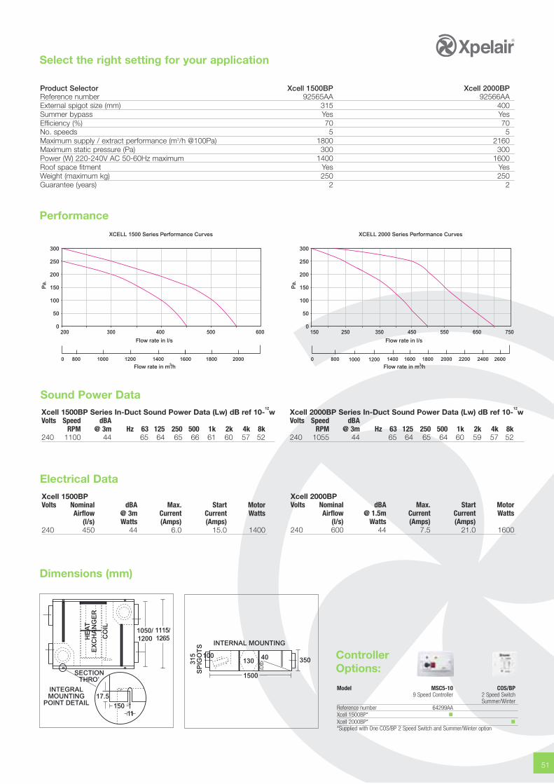
51
Select the right setting for your application
Product Selector Xcell 1500BP Xcell 2000BPReference number 92565AA 92566AAExternal spigot size (mm) 315 400Summer bypass Yes YesEfficiency (%) 70 70No. speeds 5 5Maximum supply / extract performance (m3/h @100Pa) 1800 2160Maximum static pressure (Pa) 300 300Power (W) 220-240V AC 50-60Hz maximum 1400 1600Roof space fitment Yes YesWeight (maximum kg) 250 250Guarantee (years) 2 2
Dimensions (mm)
1050/1200
1115/1265
15017.5
INTEGRALMOUNTING
POINT DETAIL
SECTIONTHRO’
CO
IL
HE
AT
EX
CH
AN
GE
R
350
INTERNAL MOUNTING
315
SP
IGO
TS
1500
100130 40
300
250
200
150
100
50
0
Pa.
200 300 400 500 600
XCELL 1500 Series Performance Curves
0 12001000 1800 20001400800 1600
Flow rate in l/s
Flow rate in m /h3
300
250
200
150
100
50
0
Pa.
150 250 350 450 550 650 750
XCELL 2000 Series Performance Curves
0 1000 1200 1400 1600 1800800 2400 26002000 2200
Flow rate in l/s
Flow rate in m /h3
Sound Power Data
Performance
Xcell 1500BPVolts Nominal dBA Max. Start Motor
Airflow @ 3m Current Current Watts(l/s) Watts (Amps) (Amps)
240 450 44 6.0 15.0 1400
Xcell 1500BP Series In-Duct Sound Power Data (Lw) dB ref 10-12w
Volts Speed dBARPM @ 3m Hz 63 125 250 500 1k 2k 4k 8k
240 1100 44 65 64 65 66 61 60 57 52
Xcell 2000BP Series In-Duct Sound Power Data (Lw) dB ref 10-12w
Volts Speed dBARPM @ 3m Hz 63 125 250 500 1k 2k 4k 8k
240 1055 44 65 64 65 64 60 59 57 52
Electrical DataXcell 2000BPVolts Nominal dBA Max. Start Motor
Airflow @ 1.5m Current Current Watts(l/s) Watts (Amps) (Amps)
240 600 44 7.5 21.0 1600
ControllerOptions:
Model MSC5-10 COS/BP9 Speed Controller 2 Speed Switch
Summer/WinterReference number 64299AAXcell 1500BP* �Xcell 2000BP* �*Supplied with One COS/BP 2 Speed Switch and Summer/Winter option
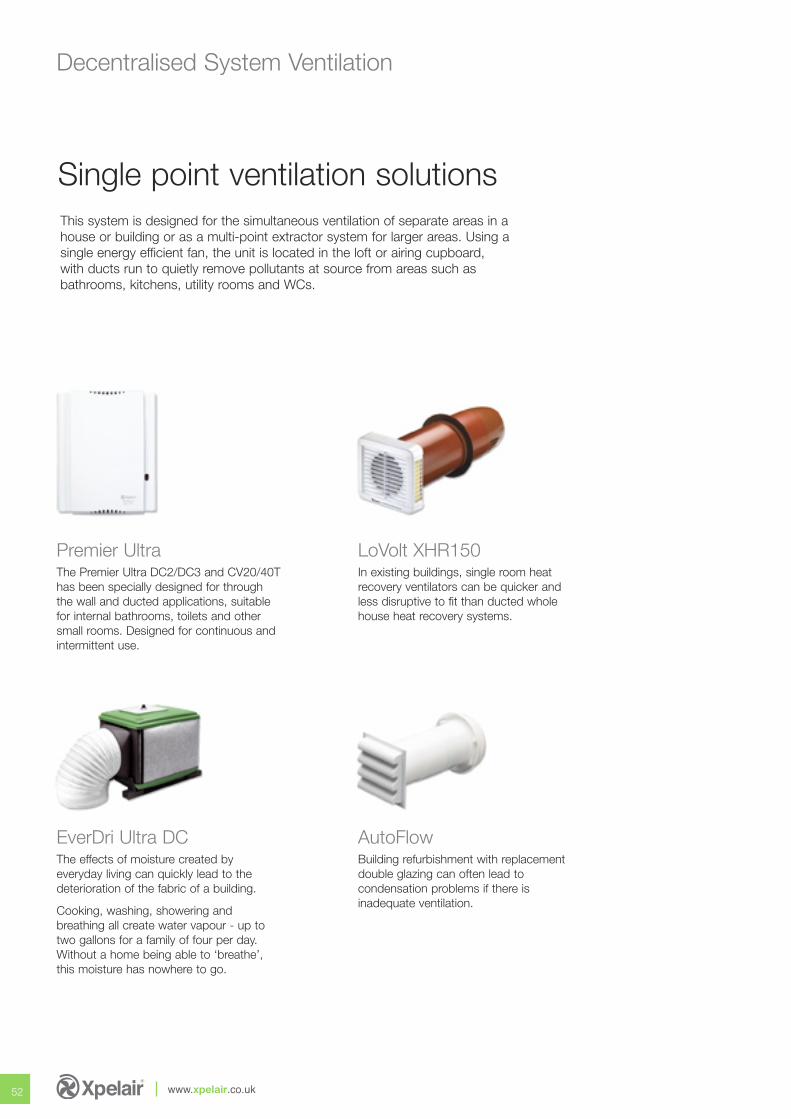
52 www.xpelair.co.uk
Decentralised System Ventilation
This system is designed for the simultaneous ventilation of separate areas in ahouse or building or as a multi-point extractor system for larger areas. Using asingle energy efficient fan, the unit is located in the loft or airing cupboard, with ducts run to quietly remove pollutants at source from areas such asbathrooms, kitchens, utility rooms and WCs.
Single point ventilation solutions
The Premier Ultra DC2/DC3 and CV20/40Thas been specially designed for throughthe wall and ducted applications, suitablefor internal bathrooms, toilets and othersmall rooms. Designed for continuous andintermittent use.
Premier UltraIn existing buildings, single room heatrecovery ventilators can be quicker andless disruptive to fit than ducted wholehouse heat recovery systems.
LoVolt XHR150
The effects of moisture created byeveryday living can quickly lead to thedeterioration of the fabric of a building.
Cooking, washing, showering andbreathing all create water vapour - up totwo gallons for a family of four per day.Without a home being able to ‘breathe’,this moisture has nowhere to go.
EverDri Ultra DCBuilding refurbishment with replacementdouble glazing can often lead tocondensation problems if there isinadequate ventilation.
AutoFlow
fresh airpure and simple
53

The Premier Ultra DC2/3 has been specially designed for through the wall and ducted applications. It is also suitable for internalbathrooms, toilets and other small rooms.
Finished in white, the DC2/3 can be flush or surface mounted, with a 100mm circular spigot for rear entry or via the knock out connection for flatvertical ducting system. A simple to remove front cover, removable impeller and easy fit motor cassette feature simplifies maintenance and assistsin quick and simple installation.
The DC2/3 incorporates a constant trickle feature, which means that when units are installed in every wet area of the property it can be classed asa whole house system, allowing it to comply with current building regulations for either intermittent or continuous extract. The Premier has versatilestandard built-in options, which allows the installer to select a combination of features: humidity control, adjustable overrun timer and ‘Quick Visit’delay start and pullcord boost override.
Key Features
• Intermittent operation selectable
• Extra long life UltraDC motors
• Easy fit motor cassette feature
• Filterless, easy maintenance
• Meets Building Regulations for continuous and intermittent use
• Suitable for wall or ceiling mounting
• Removable impeller for cleaning and ease of maintenance
• Humidity control (CF model)
• 5 year motor guarantee
• SELV and integrated transformer models
• IPX5 suitable for wet zones 1&2
54 www.xpelair.co.uk
Wall mounting
Premier UltraDC2 & DC3 Fan Range Decentralised Extract System
The Range
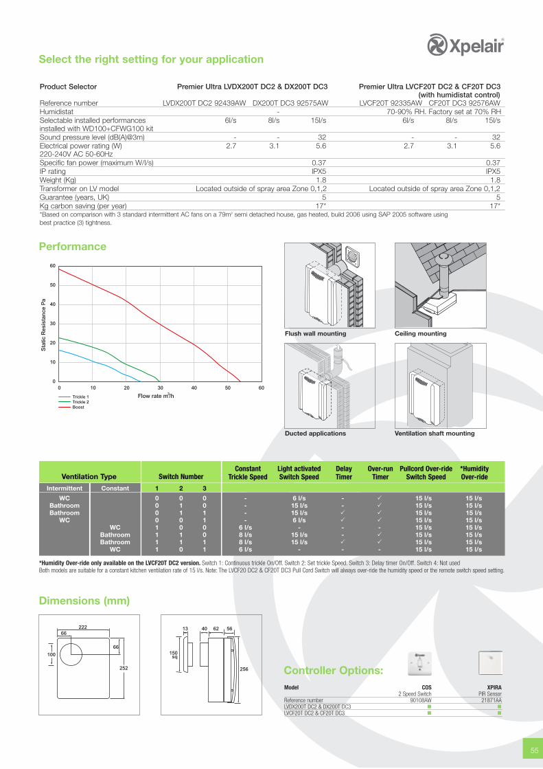
Select the right setting for your application
55
00
10
10
20
20
30
30
40
40
50
50
60
60
Sta
tic R
esis
tan
ce P
a
Flow rate m /h3Trickle 1Trickle 2Boost
Performance
Product Selector Premier Ultra LVDX200T DC2 & DX200T DC3 Premier Ultra LVCF20T DC2 & CF20T DC3(with humidistat control)
Reference number LVDX200T DC2 92439AW DX200T DC3 92575AW LVCF20T 92335AW CF20T DC3 92576AWHumidistat - 70-90% RH. Factory set at 70% RHSelectable installed performances 6l/s 8l/s 15l/s 6l/s 8l/s 15l/sinstalled with WD100+CFWG100 kitSound pressure level (dB(A)@3m) - - 32 - - 32Electrical power rating (W) 2.7 3.1 5.6 2.7 3.1 5.6220-240V AC 50-60HzSpecific fan power (maximum W/l/s) 0.37 0.37IP rating IPX5 IPX5Weight (Kg) 1.8 1.8Transformer on LV model Located outside of spray area Zone 0,1,2 Located outside of spray area Zone 0,1,2Guarantee (years, UK) 5 5Kg carbon saving (per year) 17* 17**Based on comparison with 3 standard intermittent AC fans on a 79m2 semi detached house, gas heated, build 2006 using SAP 2005 software usingbest practice (3) tightness.
Dimensions (mm)
100
66
66
222
252
150sq
13 40 62 56
256
Flush wall mounting Ceiling mounting
Ducted applications Ventilation shaft mounting
Ventilation Type
Intermittent Constant
WCBathroomBathroom
WCWC
BathroomBathroom
WC
Switch Number
1 2 3
0 0 0 - 6 l/s - � 15 l/s 15 l/s0 1 0 - 15 l/s - � 15 l/s 15 l/s0 1 1 - 15 l/s � � 15 l/s 15 l/s0 0 1 - 6 l/s � � 15 l/s 15 l/s1 0 0 6 l/s - - - 15 l/s 15 l/s1 1 0 8 l/s 15 l/s - � 15 l/s 15 l/s1 1 1 8 l/s 15 l/s � � 15 l/s 15 l/s1 0 1 6 l/s - - - 15 l/s 15 l/s
Constant Light activated Delay Over-run Pullcord Over-ride *HumidityTrickle Speed Switch Speed Timer Timer Switch Speed Over-ride
*Humidity Over-ride only available on the LVCF20T DC2 version. Switch 1: Continuous trickle On/Off. Switch 2: Set trickle Speed. Switch 3: Delay timer On/Off. Switch 4: Not usedBoth models are suitable for a constant kitchen ventilation rate of 15 l/s. Note: The LVCF20 DC2 & CF20T DC3 Pull Cord Switch will always over-ride the humidity speed or the remote switch speed setting.
Model COS XPIRA2 Speed Switch PIR Sensor
Reference number 90108AW 21871AALVDX200T DC2 & DX200T DC3 � �LVCF20T DC2 & CF20T DC3 � �
Controller Options:

The Premier CF20/40T CV model features Ultra EC technology offering reduced energy use, a choice of installed performancesand a longer life than a conventional AC motor.
The fan is designed to comply with the requirements of Part F1 to provide Intermittent Ventilation in Kitchens, Utility rooms, Bathrooms and SanitaryRooms, Humidity Controlled intermittent Ventilation + manual over-ride in Kitchens and Bathrooms, Intermittent Ventilation in Internal rooms andDecentralised Continuous Ventilation in Kitchens, Utility Rooms, Bathrooms and Sanitary Rooms.
Performance is set at installation via a series of internal dip switches. The Constant Volume nature of the fan means that performance remainsconstant irrespective of the installed condition up to a system pressure of 100Pa. The fan can be surface or flush mounted in walls and ceilingsusing the universal mounting accessories provided.
The fan is provided with a back draught shutter for intermittent applications. It is not to be fitted for the lower velocity continuous decentralisedapplications. Control options include integral Humidistat, pullcord over-ride, run on timer and 'quick visit' delay start facility. Xpelair offers a 5 yearUK only guarantee.
56 www.xpelair.co.uk
Premier UltraCF20/40T CV Fan Range Decentralised Extract System
The Range
Key Features
• 1 fan for all applications
• Constant volume irrespective of system resistance up to 100Pa
• Extra long life Ultra EC motors
• Filterless, easy maintenance
• Meets Building Regulations for continuous and intermittent use
• Suitable for wall or ceiling mounting
• Humidity control
• 5 year motor guarantee
• IPX5 suitable for wet zones 1&2
Wall mounting
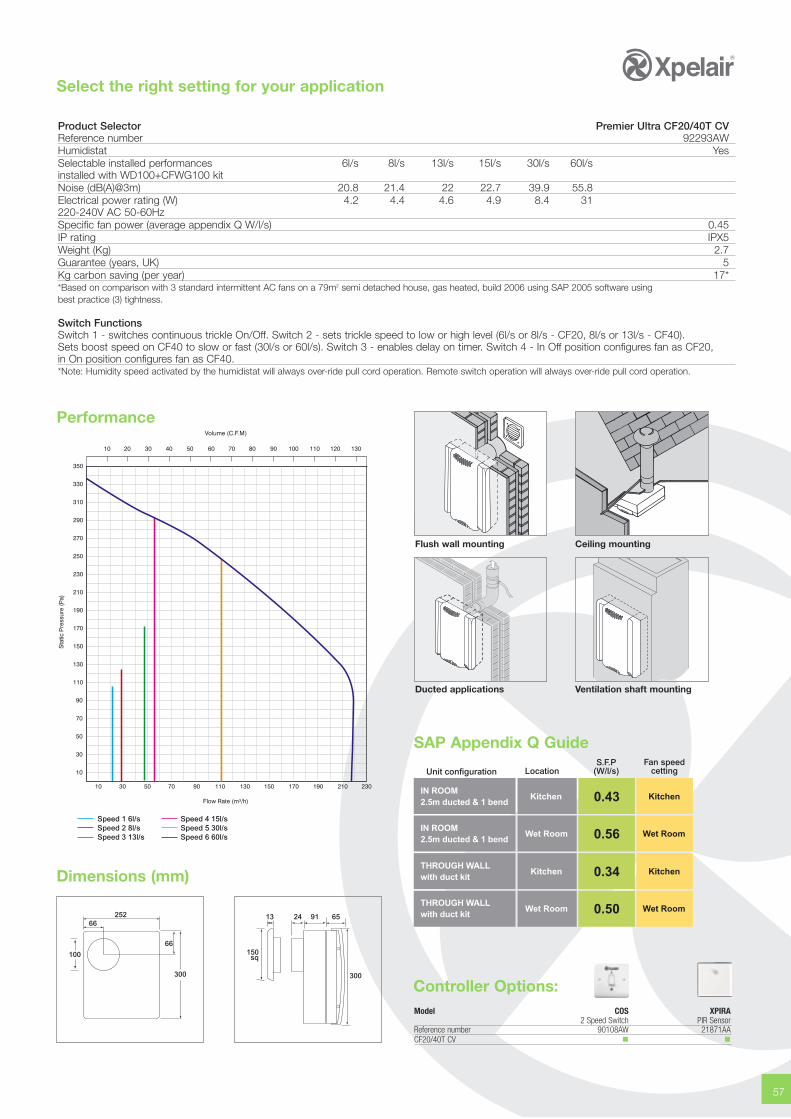
Select the right setting for your application
57
Performance
Product Selector Premier Ultra CF20/40T CVReference number 92293AWHumidistat YesSelectable installed performances 6l/s 8l/s 13l/s 15l/s 30l/s 60l/sinstalled with WD100+CFWG100 kitNoise (dB(A)@3m) 20.8 21.4 22 22.7 39.9 55.8Electrical power rating (W) 4.2 4.4 4.6 4.9 8.4 31220-240V AC 50-60HzSpecific fan power (average appendix Q W/l/s) 0.45IP rating IPX5Weight (Kg) 2.7Guarantee (years, UK) 5Kg carbon saving (per year) 17**Based on comparison with 3 standard intermittent AC fans on a 79m2 semi detached house, gas heated, build 2006 using SAP 2005 software usingbest practice (3) tightness.
Switch FunctionsSwitch 1 - switches continuous trickle On/Off. Switch 2 - sets trickle speed to low or high level (6l/s or 8l/s - CF20, 8l/s or 13l/s - CF40).Sets boost speed on CF40 to slow or fast (30l/s or 60l/s). Switch 3 - enables delay on timer. Switch 4 - In Off position configures fan as CF20,in On position configures fan as CF40.*Note: Humidity speed activated by the humidistat will always over-ride pull cord operation. Remote switch operation will always over-ride pull cord operation.
Dimensions (mm)
100
66
66
252
300
150sq
13 24 91 65
300
Flush wall mounting Ceiling mounting
Ducted applications Ventilation shaft mounting
Speed 1 6l/s Speed 2 8l/sSpeed 3 13l/s
Speed 4 15l/sSpeed 5 30l/sSpeed 6 60l/s
Fan speedcetting
S.F.P(W/l/s)LocationUnit configuration
IN ROOM2.5m ducted & 1 bend
Kitchen 0.43
IN ROOM2.5m ducted & 1 bend
Wet Room 0.56
THROUGH WALLwith duct kit
Kitchen 0.34
THROUGH WALLwith duct kit
Wet Room
Kitchen
Wet Room
Kitchen
Wet Room0.50
SAP Appendix Q Guide
Model COS XPIRA2 Speed Switch PIR Sensor
Reference number 90108AW 21871AACF20/40T CV � �
Controller Options:
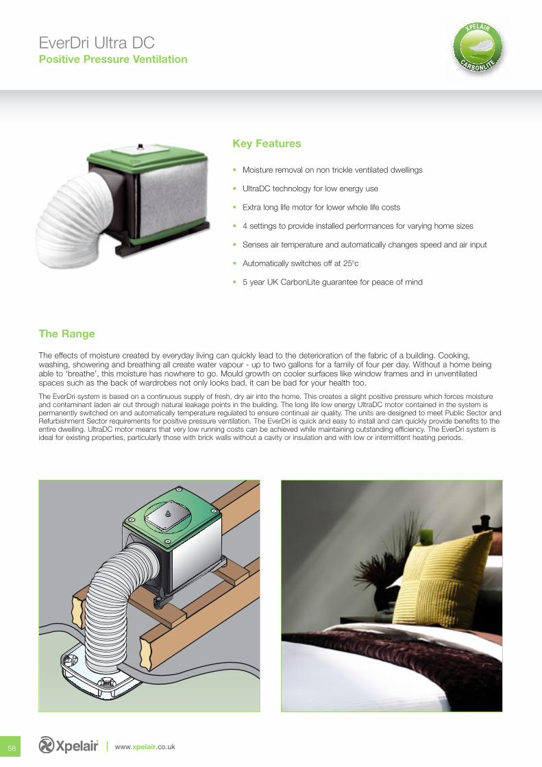
EverDri Ultra DCPositive Pressure Ventilation
Key Features
• Moisture removal on non trickle ventilated dwellings
• UltraDC technology for low energy use
• Extra long life motor for lower whole life costs
• 4 settings to provide installed performances for varying home sizes
• Senses air temperature and automatically changes speed and air input
• Automatically switches off at 250c
• 5 year UK CarbonLite guarantee for peace of mind
58 www.xpelair.co.uk
The effects of moisture created by everyday living can quickly lead to the deterioration of the fabric of a building. Cooking, washing, showering and breathing all create water vapour - up to two gallons for a family of four per day. Without a home beingable to ‘breathe’, this moisture has nowhere to go. Mould growth on cooler surfaces like window frames and in unventilatedspaces such as the back of wardrobes not only looks bad, it can be bad for your health too.
The EverDri system is based on a continuous supply of fresh, dry air into the home. This creates a slight positive pressure which forces moistureand contaminant laden air out through natural leakage points in the building. The long life low energy UltraDC motor contained in the system ispermanently switched on and automatically temperature regulated to ensure continual air quality. The units are designed to meet Public Sector andRefurbishment Sector requirements for positive pressure ventilation. The EverDri is quick and easy to install and can quickly provide benefits to theentire dwelling. UltraDC motor means that very low running costs can be achieved while maintaining outstanding efficiency. The EverDri system isideal for existing properties, particularly those with brick walls without a cavity or insulation and with low or intermittent heating periods.
The Range
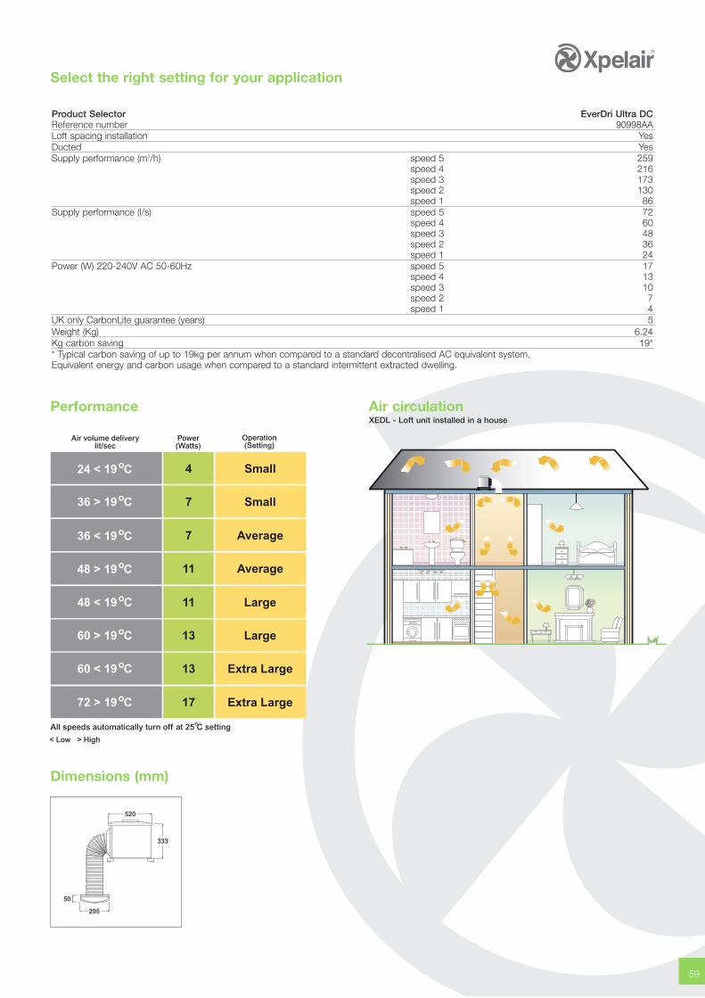
Select the right setting for your application
59
Performance Air circulationXEDL - Loft unit installed in a house
Product Selector EverDri Ultra DCReference number 90998AALoft spacing installation YesDucted YesSupply performance (m3/h) speed 5 259
speed 4 216speed 3 173speed 2 130speed 1 86
Supply performance (l/s) speed 5 72speed 4 60speed 3 48speed 2 36speed 1 24
Power (W) 220-240V AC 50-60Hz speed 5 17speed 4 13speed 3 10speed 2 7speed 1 4
UK only CarbonLite guarantee (years) 5Weight (Kg) 6.24Kg carbon saving 19** Typical carbon saving of up to 19kg per annum when compared to a standard decentralised AC equivalent system.Equivalent energy and carbon usage when compared to a standard intermittent extracted dwelling.
Dimensions (mm)
520
333
50
295
Operation(Setting)
Power(Watts)
Air volume deliverylit/sec
4 Small
7 Small
7 Average
11 Average
11 Large
13 Large
24 < 19 C o
36 > 19 C o
36 < 19 C o
48 > 19 C o
48 < 19 C o
60 > 19 C o
13 Extra Large60 < 19 C o
17 Extra Large72 > 19 C o
< Low > High
All speeds automatically turn off at 25 C settingo
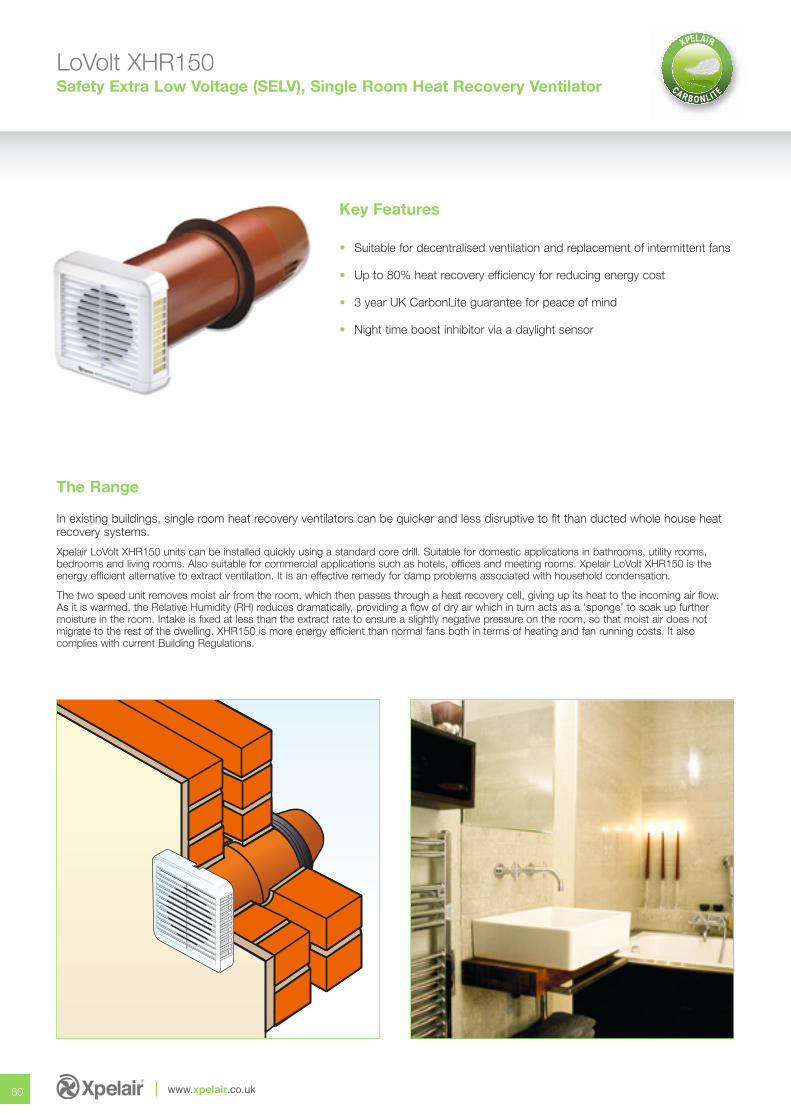
LoVolt XHR150Safety Extra Low Voltage (SELV), Single Room Heat Recovery Ventilator
Key Features
• Suitable for decentralised ventilation and replacement of intermittent fans
• Up to 80% heat recovery efficiency for reducing energy cost
• 3 year UK CarbonLite guarantee for peace of mind
• Night time boost inhibitor via a daylight sensor
60 www.xpelair.co.uk
In existing buildings, single room heat recovery ventilators can be quicker and less disruptive to fit than ducted whole house heatrecovery systems.
Xpelair LoVolt XHR150 units can be installed quickly using a standard core drill. Suitable for domestic applications in bathrooms, utility rooms, bedrooms and living rooms. Also suitable for commercial applications such as hotels, offices and meeting rooms. Xpelair LoVolt XHR150 is theenergy efficient alternative to extract ventilation. It is an effective remedy for damp problems associated with household condensation.
The two speed unit removes moist air from the room, which then passes through a heat recovery cell, giving up its heat to the incoming air flow. As it is warmed, the Relative Humidity (RH) reduces dramatically, providing a flow of dry air which in turn acts as a ‘sponge’ to soak up further moisture in the room. Intake is fixed at less than the extract rate to ensure a slightly negative pressure on the room, so that moist air does notmigrate to the rest of the dwelling. XHR150 is more energy efficient than normal fans both in terms of heating and fan running costs. It also complies with current Building Regulations.
The Range
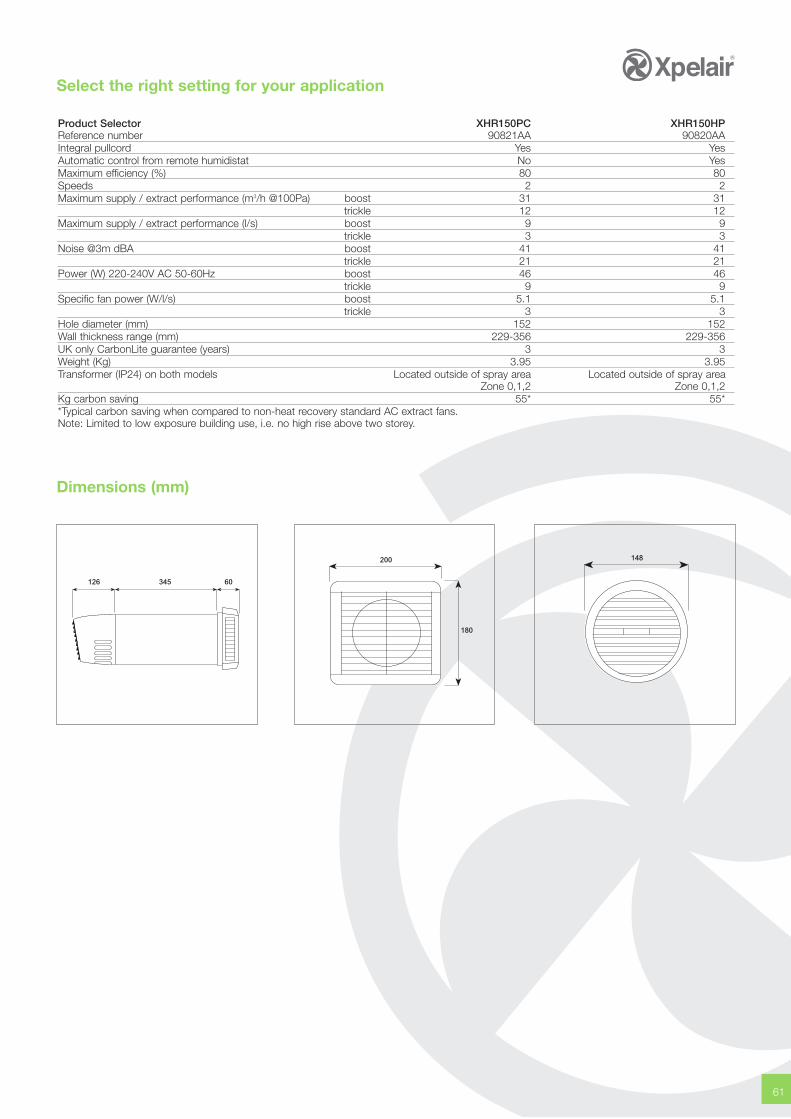
Select the right setting for your application
61
Product Selector XHR150PC XHR150HPReference number 90821AA 90820AAIntegral pullcord Yes YesAutomatic control from remote humidistat No YesMaximum efficiency (%) 80 80Speeds 2 2Maximum supply / extract performance (m3/h @100Pa) boost 31 31
trickle 12 12Maximum supply / extract performance (l/s) boost 9 9
trickle 3 3Noise @3m dBA boost 41 41
trickle 21 21Power (W) 220-240V AC 50-60Hz boost 46 46
trickle 9 9Specific fan power (W/l/s) boost 5.1 5.1
trickle 3 3Hole diameter (mm) 152 152Wall thickness range (mm) 229-356 229-356UK only CarbonLite guarantee (years) 3 3Weight (Kg) 3.95 3.95Transformer (IP24) on both models Located outside of spray area Located outside of spray area
Zone 0,1,2 Zone 0,1,2Kg carbon saving 55* 55**Typical carbon saving when compared to non-heat recovery standard AC extract fans.Note: Limited to low exposure building use, i.e. no high rise above two storey.
Dimensions (mm)
126 345 60
200
180
148
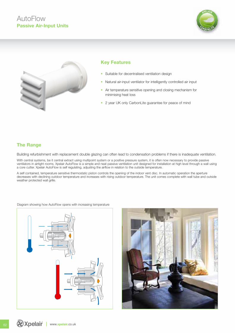
AutoFlowPassive Air-Input Units
Key Features
• Suitable for decentralised ventilation design
• Natural air-input ventilator for intelligently controlled air input
• Air temperature sensitive opening and closing mechanism for minimising heat loss
• 2 year UK only CarbonLite guarantee for peace of mind
62 www.xpelair.co.uk
Diagram showing how AutoFlow opens with increasing temperature
Building refurbishment with replacement double glazing can often lead to condensation problems if there is inadequate ventilation.
With central systems, be it central extract using multipoint system or a positive pressure system, it is often now necessary to provide passive ventilators in airtight rooms. Xpelair AutoFlow is a simple and neat passive ventilation unit designed for installation at high level through a wall usinga core cutter. Xpelair AutoFlow is self regulating, adjusting the airflow in relation to the outside temperature.
A self contained, temperature sensitive thermostatic piston controls the opening of the indoor vent disc. In automatic operation the aperturedecreases with declining outdoor temperature and increases with rising outdoor temperature. The unit comes complete with wall tube and outsideweather protected wall grille.
The Range
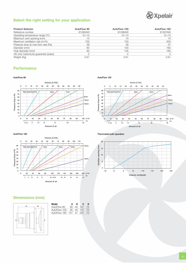
Select the right setting for your application
Dimensions (mm)
63
Performance
Product Selector AutoFlow 80 AutoFlow 100 AutoFlow 160Reference number 91295AW 91296AW 91297AWOperating temperature range (ºC) -5/+10 -5/+10 5/+10Maximum vent opening (mm) 15 15 15Maximum ventilation rate (m3/h) 100 100 200Pressure drop at max flow rate (Pa) 38 36 37Diameter (mm) 80 100 160Hole diameter (mm) 85 105 165UK only CarbonLite guarantee (years) 2 2 2Weight (Kg) 0.61 0.61 0.61
AutoFlow 80
AutoFlow 160
AutoFlow 100
Thermostat bulb operation
0 5 10 15 20 25 30 35 40 45 50 55
Volume (C.F.M.)
Amount of air
Pre
ssu
re d
rop
in P
a
Volume (C.F.M.)
Amount of air
Pre
ssu
re d
rop
in P
a
Ven
tilat
or
op
enin
g (
mm
)
Degrees centigrade
20
15
10
5
0
-10 -5 0 +5 +10 +15 +20 +25
Amount of air
Pre
ssu
re d
rop
in P
a
Model A B C DAutoFlow 80 80 40 147 75AutoFlow 100 95 40 147 75AutoFlow 160 157 47 207 75
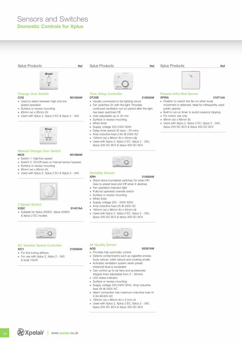
Sensors and SwitchesDomestic Controls for Xplus
64 www.xpelair.co.uk
Xplus Products Ref
Change Over SwitchCOS 90108AW� Used to select between high and low
speed operation� Surface or recess mounting� 85mm (w) x 85mm (h)� Used with Xplus 2, Xplus 2 EC & Xplus 2 - 340
Manual Change Over SwitchMOS 90199AW� Switch 1: high/low speed� Switch 2: On/Off (auto or manual sensor bypass)� Surface or recess mounting� 85mm (w) x 85mm (h)� Used with Xplus 2, Xplus 2 EC & Xplus 2 - 340
3 Speed SwitchX3SC 91457AA� Suitable for Xplus 250DC, Xplus 400DC
& Xplus 2 EC models
AC Variable Speed ControllerXIC1 21858AW � For fine tuning airflows� For use with Xplus 2, Xplus 2 - 340
& Xcell 150/R
Xplus Products Ref
Time Delay Controller DT20B 21850AW � Usually connected to the lighting circuit� Fan switches On with the light. Provides
continued ventilation run-on period after the light has been switched Off
� User adjustable up to 20 min� Surface or recess mounting� White finish� Supply voltage 220-240V 50Hz� Delay timer period 30 secs - 20 mins� Amp inductive load 2.5A @ 240V AC� 100mm (w) x 86mm (h) x 45mm (d))� Used with Xplus 2, Xplus 2 EC, Xplus 2 - 340,
Xplus 250 DC 8CV & Xplus 400 DC 8CV
Humidity SensorXRH 21856AW� Stand alone humidistat switches On when RH
rises to preset level and Off when it declines� Fan operation indicator light� Pullcord operated override switch� Surface or recess mounting� White finish� Supply voltage 220 - 240V 50Hz� Amp inductive load 2A @ 240V AC� 160mm (w) x 86mm (h) x 45mm (d)� Used with Xplus 2, Xplus 2 EC, Xplus 2 - 340,
Xplus 250 DC 8CV & Xplus 400 DC 8CV
Air Quality SensorAQS 92097AW� Provides fully automatic control� Detects contaminants such as cigarette smoke,
body odours, toilet odours and cooking smells� Activates ventilation system when preset
threshold level is exceeded� Can control up to six fans and accessories.
Integral timer adjustable from 3 - 30mins� LED status indicator� Surface or recess mounting� Supply voltage 220-240V 50Hz. Amp inductive
load 3A @ 240V AC� Alarm connection has maximum inductive load of
0.3A @240V AC� 160mm (w) x 86mm (h) x 41mm (d� Used with Xplus 2, Xplus 2 EC, Xplus 2 - 340,
Xplus 250 DC 8CV & Xplus 400 DC 8CV
Xplus Products Ref
Passive Infra Red Sensor XPIRA 21871AA � Position to switch the fan on when body
movement is detected. Ideal for infrequently used public spaces
� Built-in run-on timer to avoid nuisance tripping� For indoor use only� 86mm (w) x 86mm (h)� Used with Xplus 2, Xplus 2 EC, Xplus 2 - 340,
Xplus 250 DC 8CV & Xplus 400 DC 8CV
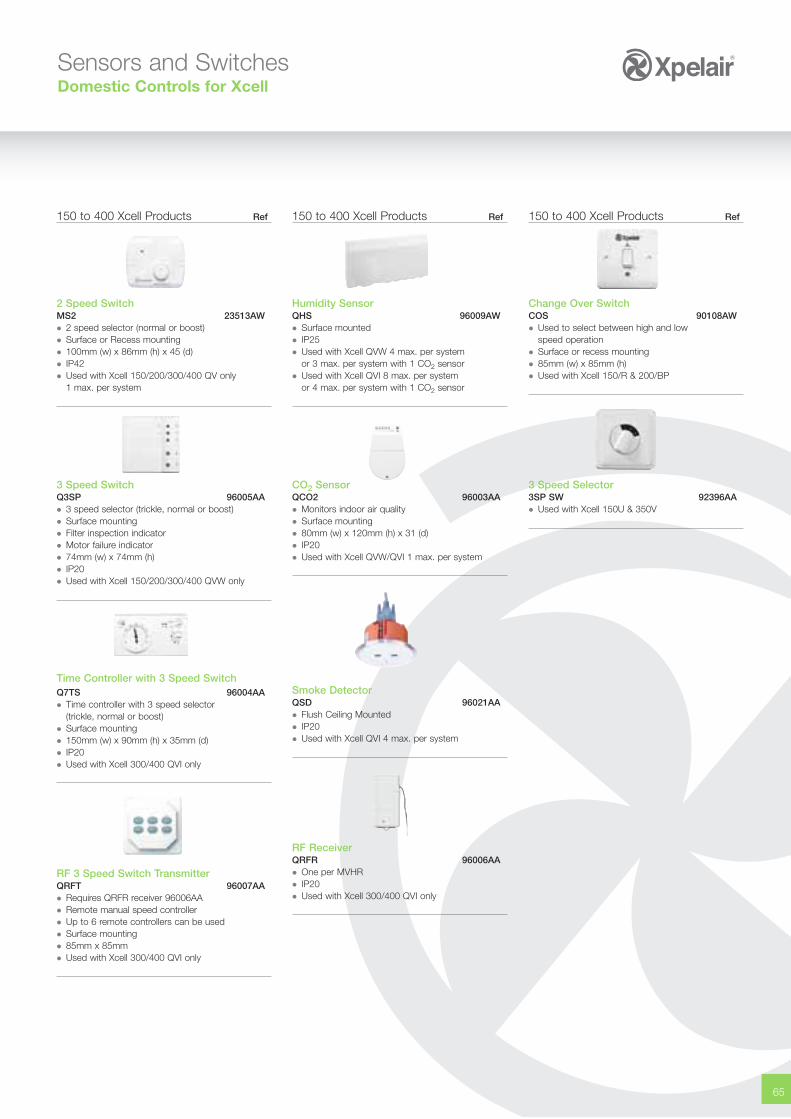
65
150 to 400 Xcell Products Ref
Change Over SwitchCOS 90108AW� Used to select between high and low
speed operation� Surface or recess mounting� 85mm (w) x 85mm (h)� Used with Xcell 150/R & 200/BP
3 Speed Selector3SP SW 92396AA� Used with Xcell 150U & 350V
150 to 400 Xcell Products Ref
2 Speed SwitchMS2 23513AW� 2 speed selector (normal or boost)� Surface or Recess mounting� 100mm (w) x 86mm (h) x 45 (d)� IP42� Used with Xcell 150/200/300/400 QV only
1 max. per system
3 Speed SwitchQ3SP 96005AA� 3 speed selector (trickle, normal or boost)� Surface mounting� Filter inspection indicator� Motor failure indicator� 74mm (w) x 74mm (h)� IP20� Used with Xcell 150/200/300/400 QVW only
Time Controller with 3 Speed SwitchQ7TS 96004AA� Time controller with 3 speed selector
(trickle, normal or boost)� Surface mounting� 150mm (w) x 90mm (h) x 35mm (d)� IP20� Used with Xcell 300/400 QVI only
RF 3 Speed Switch Transmitter QRFT 96007AA� Requires QRFR receiver 96006AA� Remote manual speed controller� Up to 6 remote controllers can be used� Surface mounting� 85mm x 85mm� Used with Xcell 300/400 QVI only
150 to 400 Xcell Products Ref
Humidity SensorQHS 96009AW� Surface mounted� IP25� Used with Xcell QVW 4 max. per system
or 3 max. per system with 1 CO2 sensor� Used with Xcell QVI 8 max. per system
or 4 max. per system with 1 CO2 sensor
CO2 SensorQCO2 96003AA� Monitors indoor air quality� Surface mounting� 80mm (w) x 120mm (h) x 31 (d)� IP20� Used with Xcell QVW/QVI 1 max. per system
Smoke DetectorQSD 96021AA� Flush Ceiling Mounted� IP20� Used with Xcell QVI 4 max. per system
RF Receiver QRFR 96006AA� One per MVHR� IP20� Used with Xcell 300/400 QVI only
Sensors and SwitchesDomestic Controls for Xcell
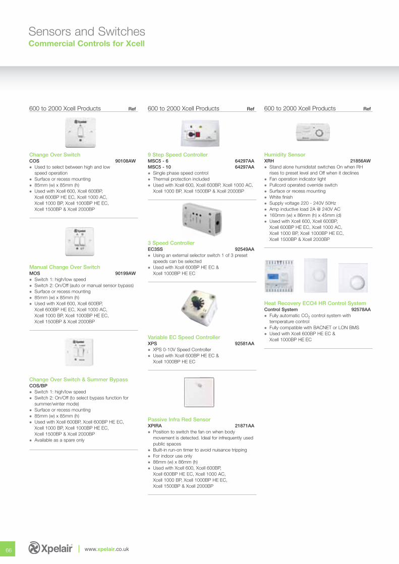
66 www.xpelair.co.uk
600 to 2000 Xcell Products Ref
Change Over SwitchCOS 90108AW� Used to select between high and low
speed operation� Surface or recess mounting� 85mm (w) x 85mm (h)� Used with Xcell 600, Xcell 600BP,
Xcell 600BP HE EC, Xcell 1000 AC, Xcell 1000 BP, Xcell 1000BP HE EC,Xcell 1500BP & Xcell 2000BP
Manual Change Over SwitchMOS 90199AW� Switch 1: high/low speed� Switch 2: On/Off (auto or manual sensor bypass)� Surface or recess mounting� 85mm (w) x 85mm (h)� Used with Xcell 600, Xcell 600BP,
Xcell 600BP HE EC, Xcell 1000 AC, Xcell 1000 BP, Xcell 1000BP HE EC,Xcell 1500BP & Xcell 2000BP
Change Over Switch & Summer BypassCOS/BP� Switch 1: high/low speed� Switch 2: On/Off (to select bypass function for
summer/winter mode)� Surface or recess mounting� 85mm (w) x 85mm (h)� Used with Xcell 600BP, Xcell 600BP HE EC,
Xcell 1000 BP, Xcell 1000BP HE EC,Xcell 1500BP & Xcell 2000BP
� Available as a spare only
600 to 2000 Xcell Products Ref
9 Step Speed Controller MSC5 - 6 64297AAMSC5 - 10 64297AA� Single phase speed control� Thermal protection included� Used with Xcell 600, Xcell 600BP, Xcell 1000 AC,
Xcell 1000 BP, Xcell 1500BP & Xcell 2000BP
3 Speed ControllerEC3SS 92549AA� Using an external selector switch 1 of 3 preset
speeds can be selected� Used with Xcell 600BP HE EC &
Xcell 1000BP HE EC
Variable EC Speed ControllerXPS 92581AA� XPS 0-10V Speed Controller� Used with Xcell 600BP HE EC &
Xcell 1000BP HE EC
Passive Infra Red Sensor XPIRA 21871AA � Position to switch the fan on when body
movement is detected. Ideal for infrequently used public spaces
� Built-in run-on timer to avoid nuisance tripping� For indoor use only� 86mm (w) x 86mm (h)� Used with Xcell 600, Xcell 600BP,
Xcell 600BP HE EC, Xcell 1000 AC, Xcell 1000 BP, Xcell 1000BP HE EC,Xcell 1500BP & Xcell 2000BP
600 to 2000 Xcell Products Ref
Humidity SensorXRH 21856AW� Stand alone humidistat switches On when RH
rises to preset level and Off when it declines� Fan operation indicator light� Pullcord operated override switch� Surface or recess mounting� White finish� Supply voltage 220 - 240V 50Hz� Amp inductive load 2A @ 240V AC� 160mm (w) x 86mm (h) x 45mm (d)� Used with Xcell 600, Xcell 600BP,
Xcell 600BP HE EC, Xcell 1000 AC, Xcell 1000 BP, Xcell 1000BP HE EC,Xcell 1500BP & Xcell 2000BP
Heat Recovery ECO4 HR Control SystemControl System 92578AA� Fully automatic CO2 control system with
temperature control� Fully compatible with BACNET or LON BMS� Used with Xcell 600BP HE EC &
Xcell 1000BP HE EC
Sensors and SwitchesCommercial Controls for Xcell
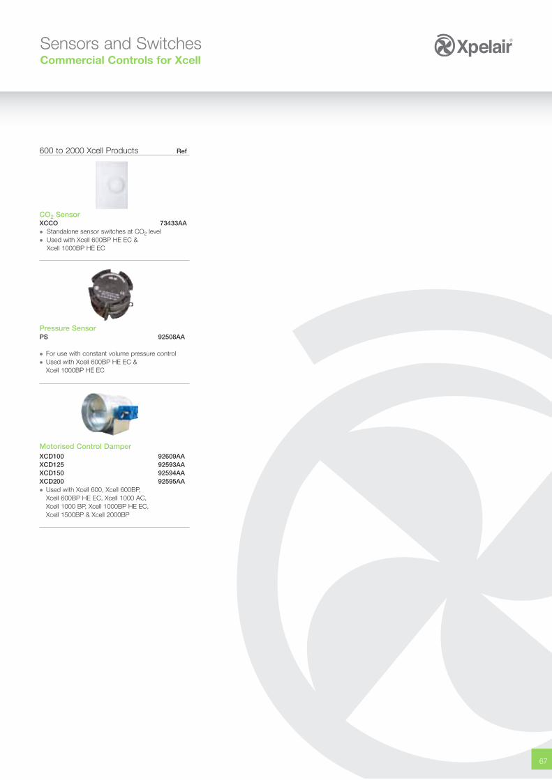
67
600 to 2000 Xcell Products Ref
CO2 SensorXCCO 73433AA� Standalone sensor switches at CO2 level� Used with Xcell 600BP HE EC &
Xcell 1000BP HE EC
Pressure SensorPS 92508AA
� For use with constant volume pressure control� Used with Xcell 600BP HE EC &
Xcell 1000BP HE EC
Motorised Control DamperXCD100 92609AAXCD125 92593AAXCD150 92594AAXCD200 92595AA� Used with Xcell 600, Xcell 600BP,
Xcell 600BP HE EC, Xcell 1000 AC, Xcell 1000 BP, Xcell 1000BP HE EC,Xcell 1500BP & Xcell 2000BP
Sensors and SwitchesCommercial Controls for Xcell
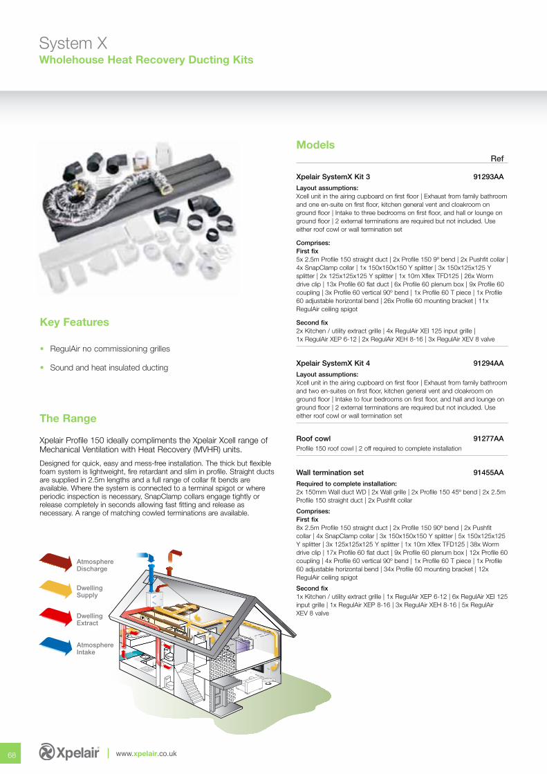
68 www.xpelair.co.uk
System XWholehouse Heat Recovery Ducting Kits
Models
Xpelair Profile 150 ideally compliments the Xpelair Xcell range ofMechanical Ventilation with Heat Recovery (MVHR) units.
Designed for quick, easy and mess-free installation. The thick but flexiblefoam system is lightweight, fire retardant and slim in profile. Straight ductsare supplied in 2.5m lengths and a full range of collar fit bends areavailable. Where the system is connected to a terminal spigot or whereperiodic inspection is necessary, SnapClamp collars engage tightly orrelease completely in seconds allowing fast fitting and release asnecessary. A range of matching cowled terminations are available.
The Range
Ref
Xpelair SystemX Kit 3 91293AA
Layout assumptions: Xcell unit in the airing cupboard on first floor | Exhaust from family bathroomand one en-suite on first floor, kitchen general vent and cloakroom onground floor | Intake to three bedrooms on first floor, and hall or lounge onground floor | 2 external terminations are required but not included. Useeither roof cowl or wall termination set
Comprises:First fix5x 2.5m Profile 150 straight duct | 2x Profile 150 9º bend | 2x Pushfit collar |4x SnapClamp collar | 1x 150x150x150 Y splitter | 3x 150x125x125 Ysplitter | 2x 125x125x125 Y splitter | 1x 10m Xflex TFD125 | 26x Wormdrive clip | 13x Profile 60 flat duct | 6x Profile 60 plenum box | 9x Profile 60coupling | 3x Profile 60 vertical 90º bend | 1x Profile 60 T piece | 1x Profile60 adjustable horizontal bend | 26x Profile 60 mounting bracket | 11xRegulAir ceiling spigot
Second fix2x Kitchen / utility extract grille | 4x RegulAir XEI 125 input grille | 1x RegulAir XEP 6-12 | 2x RegulAir XEH 8-16 | 3x RegulAir XEV 8 valve
Xpelair SystemX Kit 4 91294AA
Layout assumptions: Xcell unit in the airing cupboard on first floor | Exhaust from family bathroomand two en-suites on first floor, kitchen general vent and cloakroom onground floor | Intake to four bedrooms on first floor, and hall and lounge onground floor | 2 external terminations are required but not included. Useeither roof cowl or wall termination set
Roof cowl 91277AAProfile 150 roof cowl | 2 off required to complete installation
Wall termination set 91455AA
Required to complete installation:2x 150mm Wall duct WD | 2x Wall grille | 2x Profile 150 45º bend | 2x 2.5mProfile 150 straight duct | 2x Pushfit collar
Comprises:First fix8x 2.5m Profile 150 straight duct | 2x Profile 150 90º bend | 2x Pushfitcollar | 4x SnapClamp collar | 3x 150x150x150 Y splitter | 5x 150x125x125Y splitter | 3x 125x125x125 Y splitter | 1x 10m Xflex TFD125 | 38x Wormdrive clip | 17x Profile 60 flat duct | 9x Profile 60 plenum box | 12x Profile 60coupling | 4x Profile 60 vertical 90º bend | 1x Profile 60 T piece | 1x Profile60 adjustable horizontal bend | 34x Profile 60 mounting bracket | 12xRegulAir ceiling spigot
Second fix1x Kitchen / utility extract grille | 1x RegulAir XEP 6-12 | 6x RegulAir XEI 125input grille | 1x RegulAir XEP 8-16 | 3x RegulAir XEH 8-16 | 5x RegulAir XEV 8 valve
Key Features
• RegulAir no commissioning grilles
• Sound and heat insulated ducting
AtmosphereDischarge
DwellingSupply
DwellingExtract
AtmosphereIntake
69
fresh airpure and simple
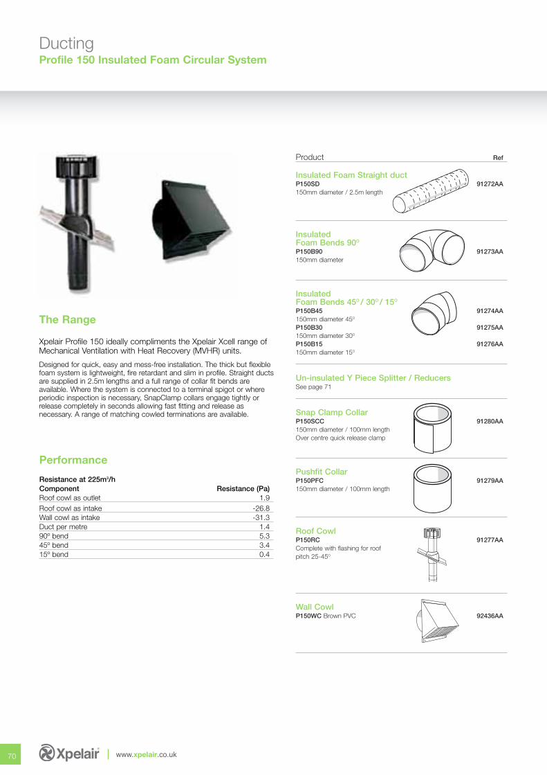
70 www.xpelair.co.uk
DuctingProfile 150 Insulated Foam Circular System
Xpelair Profile 150 ideally compliments the Xpelair Xcell range ofMechanical Ventilation with Heat Recovery (MVHR) units.
Designed for quick, easy and mess-free installation. The thick but flexiblefoam system is lightweight, fire retardant and slim in profile. Straight ductsare supplied in 2.5m lengths and a full range of collar fit bends areavailable. Where the system is connected to a terminal spigot or whereperiodic inspection is necessary, SnapClamp collars engage tightly orrelease completely in seconds allowing fast fitting and release asnecessary. A range of matching cowled terminations are available.
The Range
Performance
Resistance at 225m3/hComponent Resistance (Pa)Roof cowl as outlet 1.9Roof cowl as intake -26.8Wall cowl as intake -31.3Duct per metre 1.490º bend 5.345º bend 3.415º bend 0.4
Product Ref
Insulated Foam Straight ductP150SD 91272AA150mm diameter / 2.5m length
InsulatedFoam Bends 90O
P150B90 91273AA150mm diameter
InsulatedFoam Bends 45O / 30O / 15O
P150B45 91274AA150mm diameter 45O
P150B30 91275AA150mm diameter 30O
P150B15 91276AA150mm diameter 15O
Un-insulated Y Piece Splitter / ReducersSee page 71
Snap Clamp CollarP150SCC 91280AA150mm diameter / 100mm lengthOver centre quick release clamp
Pushfit CollarP150PFC 91279AA150mm diameter / 100mm length
Roof CowlP150RC 91277AAComplete with flashing for roofpitch 25-45O
Wall CowlP150WC Brown PVC 92436AA
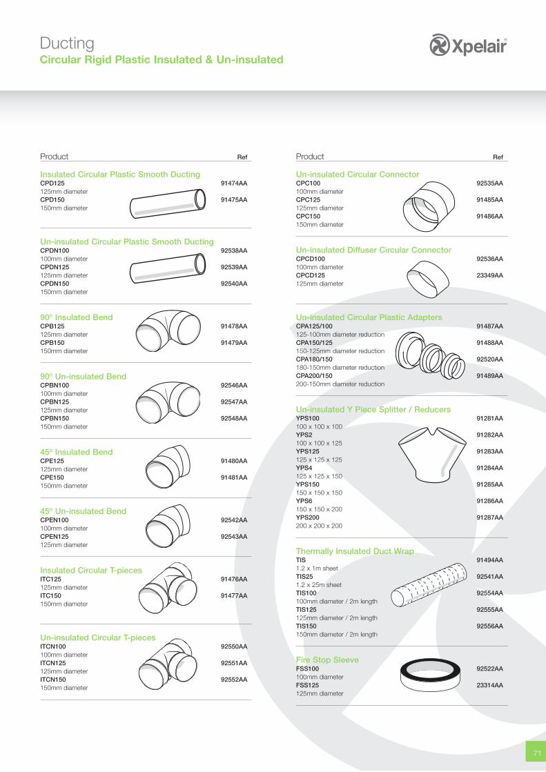
71
DuctingCircular Rigid Plastic Insulated & Un-insulated
Product Ref
Insulated Circular Plastic Smooth DuctingCPD125 91474AA125mm diameterCPD150 91475AA150mm diameter
Un-insulated Circular Plastic Smooth DuctingCPDN100 92538AA100mm diameterCPDN125 92539AA125mm diameterCPDN150 92540AA150mm diameter
90O Insulated BendCPB125 91478AA125mm diameterCPB150 91479AA150mm diameter
90O Un-insulated BendCPBN100 92546AA100mm diameterCPBN125 92547AA125mm diameterCPBN150 92548AA150mm diameter
45O Insulated BendCPE125 91480AA125mm diameterCPE150 91481AA150mm diameter
45O Un-insulated BendCPEN100 92542AA100mm diameterCPEN125 92543AA125mm diameter
Insulated Circular T-piecesITC125 91476AA125mm diameterITC150 91477AA150mm diameter
Un-insulated Circular T-piecesITCN100 92550AA100mm diameterITCN125 92551AA125mm diameterITCN150 92552AA150mm diameter
Product Ref
Un-insulated Circular ConnectorCPC100 92535AA100mm diameterCPC125 91485AA125mm diameterCPC150 91486AA150mm diameter
Un-insulated Diffuser Circular ConnectorCPCD100 92536AA100mm diameterCPCD125 23349AA125mm diameter
Un-insulated Circular Plastic AdaptersCPA125/100 91487AA125-100mm diameter reductionCPA150/125 91488AA150-125mm diameter reductionCPA180/150 92520AA180-150mm diameter reductionCPA200/150 91489AA200-150mm diameter reduction
Un-insulated Y Piece Splitter / ReducersYPS100 91281AA100 x 100 x 100YPS2 91282AA100 x 100 x 125YPS125 91283AA125 x 125 x 125YPS4 91284AA125 x 125 x 150YPS150 91285AA150 x 150 x 150YPS6 91286AA150 x 150 x 200YPS200 91287AA200 x 200 x 200
Thermally Insulated Duct WrapTIS 91494AA1.2 x 1m sheetTIS25 92541AA1.2 x 25m sheetTIS100 92554AA100mm diameter / 2m lengthTIS125 92555AA125mm diameter / 2m lengthTIS150 92556AA150mm diameter / 2m length
Fire Stop SleeveFSS100 92522AA100mm diameterFSS125 23314AA125mm diameter
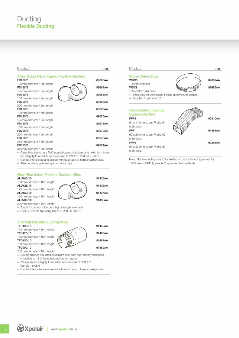
72 www.xpelair.co.uk
DuctingFlexible Ducting
Product Ref
Xflex Glass Fibre Fabric Flexible DuctingFD100/3 89663AA100mm diameter / 3m lengthFD125/3 89664AA125mm diameter / 3m lengthFD150/3 89665AA150mm diameter / 3m lengthFD200/3 89666AA200mm diameter / 3m lengthFD100/6 89669AA100mm diameter / 6m lengthFD125/6 89670AA125mm diameter / 6m lengthFD150/6 89671AA150mm diameter / 6m lengthFD200/6 89672AA200mm diameter / 6m lengthFD250/6 89673AA250mm diameter / 6m lengthFD315/6 89674AA315mm diameter / 6m length� Glass fibre fabric on a PVC coated close pitch steel wire helix. 54 minute
fire integrity from within as measured to BS 476: Part 20 - (1987)� Can be interlocked and sealed with duct tape to form an airtight seal� Attached to spigots using worm drive clips
New Aluminium Flexible Ducting Xflex ALU100/10 91435AA100mm diameter / 10m lengthALU125/10 91436AA125mm diameter / 10m lengthALU150/10 91437AA150mm diameter / 10m lengthALU200/10 91438AA200mm diameter / 10m length� Tough foil construction on a high strength wire helix� Over 40 minute fire rating BS 476: Part 20 (1987)
Thermal Flexible Ducting Xflex TFD100/10 91459AA100mm diameter / 10m lengthTFD125/10 91460AA125mm diameter / 10m lengthTFD150/10 91461AA150mm diameter / 10m lengthTFD200/10 91462AA200mm diameter / 10m length� Double skinned insulated aluminium duct with high density fibreglass
insulation to minimise condensation formulation� 25 minute fire integrity from within as measured to BS 476:
Part 20 - (1987)� Can be interlocked and sealed with duct tape to form an airtight seal
Product Ref
Worm Drive Clips WDC5 89682AA100mm diameterWDC8 89685AA150-200mm diameter� Steel clips for connecting flexible ductwork to spigots� Supplied in packs of 10
Un-insulated FlexibleSquare DuctingFPF5 92510AA54 x 110mm to suit Profile 540.5m longFPF 91484AA60 x 204mm to suit Profile 600.5m longFPF9 92354AA90 x 220mm to suit Profile 900.5m long
Note: Flexible ducting should be limited in use and is not approved for100% use in BRE Appendix Q approved test methods.
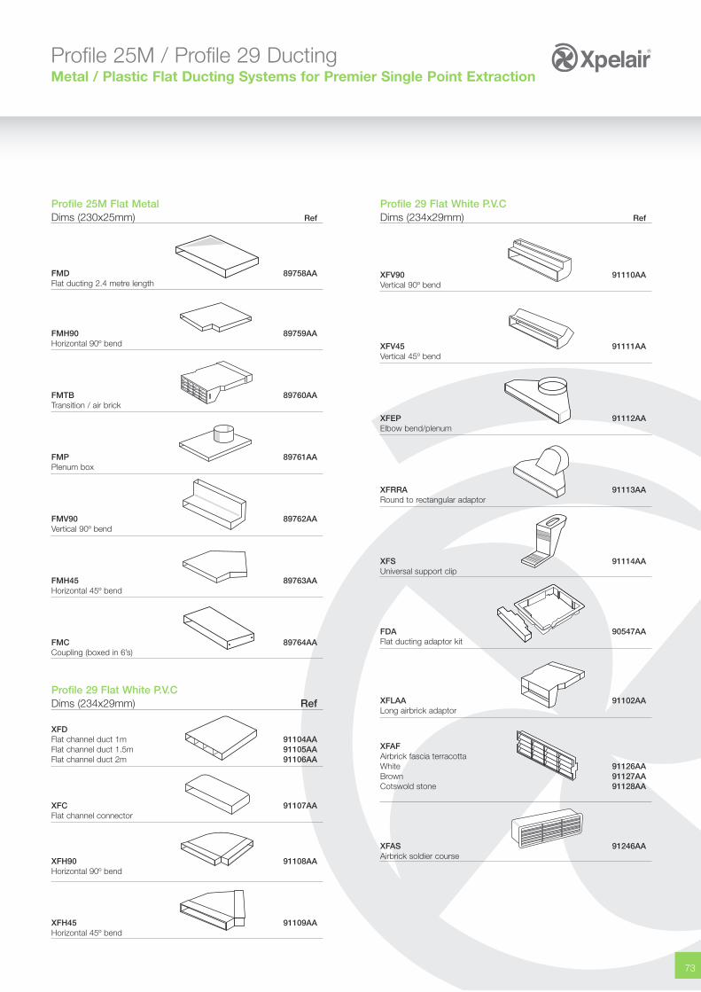
73
Profile 25M / Profile 29 DuctingMetal / Plastic Flat Ducting Systems for Premier Single Point Extraction
Profile 25M Flat MetalDims (230x25mm) Ref
FMD 89758AAFlat ducting 2.4 metre length
FMH90 89759AAHorizontal 90º bend
FMTB 89760AATransition / air brick
FMP 89761AAPlenum box
FMV90 89762AAVertical 90º bend
FMH45 89763AA Horizontal 45º bend
FMC 89764AA Coupling (boxed in 6’s)
Profile 29 Flat White P.V.CDims (234x29mm) Ref
XFDFlat channel duct 1m 91104AAFlat channel duct 1.5m 91105AAFlat channel duct 2m 91106AA
XFC 91107AAFlat channel connector
XFH90 91108AAHorizontal 90º bend
XFH45 91109AAHorizontal 45º bend
Profile 29 Flat White P.V.CDims (234x29mm) Ref
XFV90 91110AAVertical 90º bend
XFV45 91111AAVertical 45º bend
XFEP 91112AAElbow bend/plenum
XFRRA 91113AARound to rectangular adaptor
XFS 91114AAUniversal support clip
FDA 90547AAFlat ducting adaptor kit
XFLAA 91102AALong airbrick adaptor
XFAFAirbrick fascia terracottaWhite 91126AABrown 91127AACotswold stone 91128AA
XFAS 91246AAAirbrick soldier course
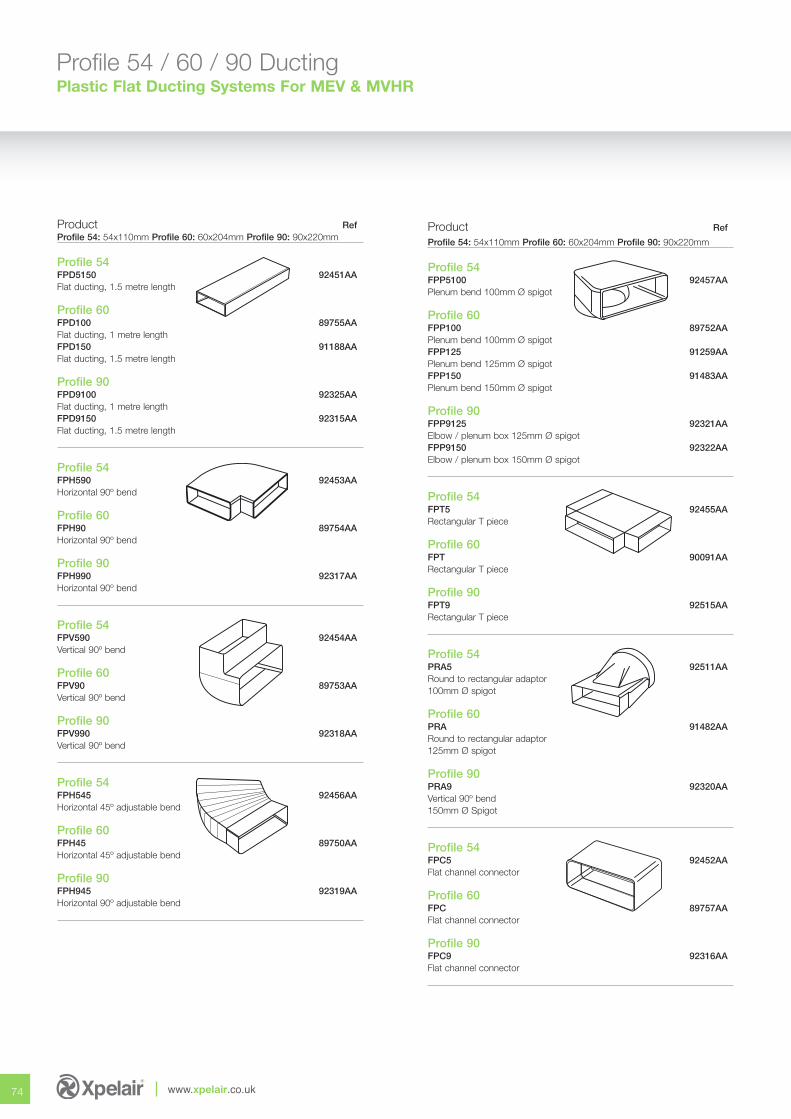
74 www.xpelair.co.uk
Profile 54 / 60 / 90 DuctingPlastic Flat Ducting Systems For MEV & MVHR
Product RefProfile 54: 54x110mm Profile 60: 60x204mm Profile 90: 90x220mm
Profile 54 FPD5150 92451AAFlat ducting, 1.5 metre length
Profile 60FPD100 89755AAFlat ducting, 1 metre lengthFPD150 91188AAFlat ducting, 1.5 metre length
Profile 90FPD9100 92325AAFlat ducting, 1 metre lengthFPD9150 92315AAFlat ducting, 1.5 metre length
Profile 54FPH590 92453AAHorizontal 90º bend
Profile 60FPH90 89754AAHorizontal 90º bend
Profile 90FPH990 92317AAHorizontal 90º bend
Profile 54FPV590 92454AAVertical 90º bend
Profile 60FPV90 89753AAVertical 90º bend
Profile 90FPV990 92318AAVertical 90º bend
Profile 54FPH545 92456AAHorizontal 45º adjustable bend
Profile 60FPH45 89750AAHorizontal 45º adjustable bend
Profile 90FPH945 92319AAHorizontal 90º adjustable bend
Product Ref
Profile 54: 54x110mm Profile 60: 60x204mm Profile 90: 90x220mm
Profile 54FPP5100 92457AAPlenum bend 100mm Ø spigot
Profile 60FPP100 89752AAPlenum bend 100mm Ø spigotFPP125 91259AAPlenum bend 125mm Ø spigotFPP150 91483AAPlenum bend 150mm Ø spigot
Profile 90FPP9125 92321AAElbow / plenum box 125mm Ø spigotFPP9150 92322AAElbow / plenum box 150mm Ø spigot
Profile 54FPT5 92455AARectangular T piece
Profile 60FPT 90091AARectangular T piece
Profile 90FPT9 92515AARectangular T piece
Profile 54PRA5 92511AARound to rectangular adaptor100mm Ø spigot
Profile 60PRA 91482AARound to rectangular adaptor125mm Ø spigot
Profile 90PRA9 92320AAVertical 90º bend150mm Ø Spigot
Profile 54FPC5 92452AAFlat channel connector
Profile 60FPC 89757AAFlat channel connector
Profile 90FPC9 92316AAFlat channel connector
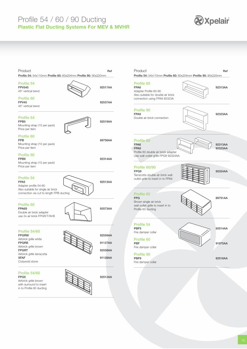
75
Profile 54 / 60 / 90 DuctingPlastic Flat Ducting Systems For MEV & MVHR
Product Ref
Profile 54: 54x110mm Profile 60: 60x204mm Profile 90: 90x220mm
Profile 54FPV545 92517AA45O vertical bend
Profile 60FPV45 92537AA45O vertical bend
Profile 54FPB5 92519AAMounting strap (10 per pack)Price per item
Profile 60FPB 89756AAMounting strap (10 per pack)Price per item
Profile 90FPB9 92314AAMounting strap (10 per pack)Price per item
Profile 54FPA5 92513AAAdapter profile 54-60Also suitable for single air brickconnection via cut to length FPB ducting
Profile 60FPA6S 92573AADouble air brick adapteruse 2x air brick FPGR/T/W/B
Profile 54/60FPGRW 92559AAAirbrick grille whiteFPGRB 91127AAAirbrick grille brownFPGRT 92558AAAirbrick grille terracottaXFAF 91128AACotswold stone
Profile 54/60FPG5 92512AAAirbrick grille brownwith surround to insertin to Profile 60 ducting
Product Ref
Profile 54: 54x110mm Profile 60: 60x204mm Profile 90: 90x220mm
Profile 60FPA6 92313AAAdapter Profile 60-90Also suitable for double air brickconnection using FPA9 92323A
Profile 90FPA9 92323AADouble air brick connection
Profile 60FPA6 92313AAFPA9 92323AAProfile 60 double air brick adapterUse wall outlet grille FPG9 92324AA
Profile 60/90FPG9 92324AATerracotta double air brick walloutlet grille to insert in to FPA9
Profile 60FPG 89751AABrown single air brickwall outlet grille to insert in toProfile 60 ducting
Profile 54PBF5 92514AAFire damper collar
Profile 60PBF 91975AAFire damper collar
Profile 90PBF9 92516AAFire damper collar
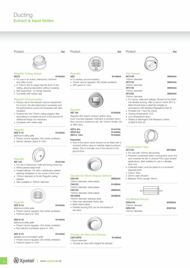
76 www.xpelair.co.uk
DuctingExtract & Input Grilles
Product Ref
RegulAir Ceiling SpigotXECS 91452AA� For use in en-suites, bathrooms, kitchens
and utility rooms� A 125mm first fix spigot that fits flush to the
ceiling, allowing decoration without masking� Self supporting - no fixings required� Complete with rubber seal
RegulAir Exhaust grilles� Factory set to the exhaust volume requirement
for a room. No site balancing is necessary and the performance cannot be tampered with after insulation
� Pushed into the 125mm ceiling adaptor after decorating is complete as part of the second fix. Additional fixings not necessary
� Complete with rubber seal
RegulAir XEE 8-16 91442AABathroom/utility grille� Preset volume regulator. 8l/s trickle ventilation� Electric damper opens to 16l/s
RegulAirXEI 125 91451AA � For use in bedrooms, halls and living rooms etc� White painted steel finish� Hinged diffuser 125 with a distribution pattern
allowing installation in the corner of the room� 125mm diameter to fit into RegulAir ceiling
adaptor� Also available in 100mm diameter
RegulAir XEP 8-16 91444AABathroom/utility grille� Preset volume regulator. 8l/s trickle ventilation� Pullcord opens to 16l/s
XEH 8-16 91445AABathroom/utility grille� Preset volume regulator. 8l/s trickle ventilation� Non-electric humidistat opens to 16l/s
XEP 6-12 91443AASanitary accommodation grille� Preset volume regulator. 6l/s trickle ventilation� Pullcord opens to 12l/s
Product Ref
RegulAirXEV 91446AA 6-12 sanitary accommodation� Preset volume regulator. 6l/s trickle ventilation� PIR opens to 12l/s
RegulAirXEI 100 91450AA
RegulAir XEV induct constant airflow valve.Duct mounted regulator maintains a constant returnflow volume to bedrooms etc. fits 125mm Profile 150or Xflex duct.
XEV4 4l/s 91447AAXEV8 8l/s 91448AAXEV12 12l/s 91449AA
Important� One of the return ducts should not be fitted with a
constant airflow valve to maintain balance extract/intake. This is normally one of the returns to the ground floor.
Circular Air Valves (Supply Extract) CAV100 89682AA100mm diameter white plasticCAV125 91490AA125mm diameter white plasticCAV150 89683AA150mm diameter white plasticVD100SS 92488AA100mm diameter stainless steel� Valve has adjustable centre disc� Multi inlets/outlets� Flexible ducting (FD) can be terminated at
the valve
Circular Air Valve Fire DamperCAV125FD 91495AA125mm diameter� Circular air valve with integral fire damper
Product Ref
Fire Damper XFC100 89843AA 100mm diameterXFC125 89844AA100mm diameterXFC150 89845AA100mm diameterXFC200 89846AA100mm diameter � For ducts, walls and ceilings. Should not be fitted
into flexible ducting. Wall or duct in which XFC is fitted should have a rated fire integrity in accordance with Building Regulations Part B
� Provides full 1 hour fire check� Closing temperature 72OC� Low temperature drop� Tested at Warrington Fire Research Centre
to BS476 Part 20
Condensation TrapXCT100 89749AA� For use with 100mm dia ducting� Prevents condensed water running back down the
duct towards the fan in vertical PVCu pipe ducted applications. (Not suitable for use in a flexible duct run)
� Collected water must be piped to a convenient disposal point
� Colour: Grey� 20mm drain off point� Material: PVCu Length: 85mm
Iris Manual DamperDIRU100 92506AA100mm diameterDIRU125 92507AA125mm diameter
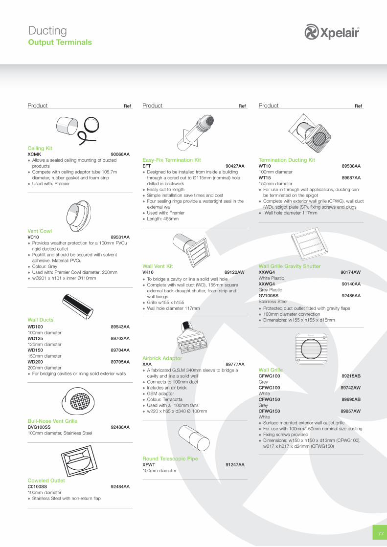
77
Product Ref
Termination Ducting Kit WT10 89538AA 100mm diameter WT15 89687AA150mm diameter � For use in through wall applications, ducting can
be terminated on the spigot� Complete with exterior wall grille (CFWG), wall duct
(WD), spigot plate (SP), fixing screws and plugs� Wall hole diameter 117mm
Wall Grille Gravity Shutter XXWG4 90174AW White PlasticXXWG4 90140AAGrey PlasticGV100SS 92485AA Stainless Steel
� Protected duct outlet fitted with gravity flaps� 100mm diameter connection� Dimensions: w155 x h155 x d15mm
Wall GrilleCFWG100 89215ABGreyCFWG100 89742AWWhiteCFWG150 89690ABGreyCFWG150 89857AWWhite� Surface mounted exterior wall outlet grille� For use with 100mm/150mm nominal size ducting� Fixing screws provided� Dimensions: w150 x h150 x d13mm (CFWG100),
w217 x h217 x d24mm (CFWG150)
Product Ref
Easy-Fix Termination KitEFT 90427AA� Designed to be installed from inside a building
through a cored out to Ø115mm (nominal) hole drilled in brickwork
� Easily cut to length� Simple installation save times and cost� Four sealing rings provide a watertight seal in the
external wall� Used with: Premier� Length: 465mm
Wall Vent KitVK10 89120AW
� To bridge a cavity or line a solid wall hole � Complete with wall duct (WD), 155mm square
external back-draught shutter, foam strip and wall fixings
� Grille w155 x h155� Wall hole diameter 117mm
Airbrick AdaptorXAA 89777AA� A fabricated G.S.M 340mm sleeve to bridge a
cavity and line a solid wall� Connects to 100mm duct� Includes an air brick� GSM adaptor� Colour: Terracotta� Used with all 100mm fans� w220 x h65 x d340 Ø 100mm
Round Telescopic Pipe XFWT 91247AA100mm diameter
Product Ref
Ceiling KitXCMK 90066AA� Allows a sealed ceiling mounting of ducted
products� Compete with ceiling adaptor tube 105.7m
diameter, rubber gasket and foam strip� Used with: Premier
Vent CowlVC10 89531AA� Provides weather protection for a 100mm PVCu
rigid ducted outlet� Pushfit and should be secured with solvent
adhesive. Material: PVCu� Colour: Grey� Used with: Premier Cowl diameter: 200mm� wØ201 x h101 x inner Ø110mm
Wall DuctsWD100 89543AA100mm diameter WD125 89703AA125mm diameterWD150 89704AA150mm diameterWD200 89705AA200mm diameter� For bridging cavities or lining solid exterior walls
Bull-Nose Vent GrilleBVG100SS 92486AA100mm diameter, Stainless Steel
Coweled OutletC0100SS 92484AA100mm diameter� Stainless Steel with non-return flap
DuctingOutput Terminals
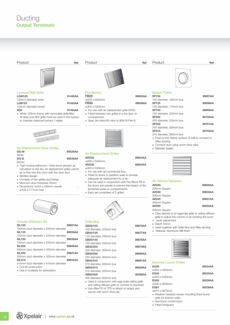
78 www.xpelair.co.uk
DuctingOutput Terminals
Product Ref
Louvred Wall Grille LGW125 91492AA125mm diameter whiteLGB125 91493AA125mm diameter brownXEK 91454AA� White 125mm frame with removable grille/filter.
At least one XEK grille must be used in the systemto maintain balanced extract / intake
Air Replacement Door Grilles DG-W 89529AA WhiteDG-B 89530AABrown� Tight closing bathroom / toilet doors prevent air
circulation to the fan. Air replacement grilles permitair to flow into the room with the door shut
� Slimline design� Consists of two grilles and fixings� Minimum door thickness 35mm� Dimensions: w454 x h90mm overall ,
w435 x h77mm hole
Circular Silencers SILSIL100 89837AA 100mm duct diameter x 200mm diameterSIL125 89838AA 125mm duct diameter x 225mm diameter SIL150 89839AA150mm duct diameter x 250mm diameter SIL200 89840AA200mm duct diameter x 300mm diameter SIL250 89841AA250mm duct diameter x 350mm diameterSIL315 89842AA315mm duct diameter x 415mm diameter � G.S.M construction� Use in multiples for attenuation
Product Ref
Fire Blocks FB20 89835AAw200 x h200mmFB30 89836AAw300 x h300mm� For use with air replacement grille (ARG)� Fitted between two grilles in a fire door or
compartment� Spec fire rated 60 mins to BS478 Part 8
Air-Replacement GrillesARG20 89833AAw200 x h200mmARG30 89834AAw300 x h300mm� For use with all commercial fans� Fitted to doors or partition walls to provide
adequate air replacement for a fan� Can be used in conjunction with Fire Block FB in
fire doors and panels to prevent the breach of fire protected areas or compartments
� Each set comprises of 2 grilles
Grille Box GB20/100 89676AA100 diameter, 200mm boxGB20/125 89677AA125 diameter, 200mm boxGB20/150 89678AA150 diameter, 200mm boxGB30/200 89679AA200 diameter, 300mm boxGB30/250 89680AA250 diameter, 300mm boxGB45/315 89681AA315 diameter, 450mm boxGB50/315 89828AA315 diameter, 500mm boxGB60/400 90296AA400 diameter, 600mm box� Used in conjunction with egg-crate ceiling grille
and ceiling diffuser grille to connect to ductwork � Use Xflex FD or TFD to attach to spigot and
secure with worm drive dip
Product Ref
Spigot PlatesSP100 89697AA100 diameter, 180mm boxSP125 89698AA125 diameter, 175mm boxSP150 89699AA 150 diameter, 200mm boxSP200 89700AA 200 diameter, 250mm boxSP250 89701AA 250 diameter, 300mm boxSP315 89702AA 315 diameter, 365mm box� Fixes to the interior surface of wall to connect to
Xflex ducting� Connect duct using worm drive clips� Material: plastic
Air Volume DampersAVD20 89829AA 200mm Square AVD30 89830AA 300mm Square AVD45 89831AA 450mm SquareAVD50 89832AA
500mm Square � Clips directly to an eggcrate grille or ceiling diffuser
grille to adjust the volume of air entering the room� Lever adjustment� Depth 44mm� Used together with Grille Box and Xflex ducting� Material: Aluminium Mill finish
External Louvre GrillesEG30 89534AA w300 x h300mm EG45 89535AAw450 x h450mm EG50 90538AAw500 x h500mmEG67 90539AA w670 x h670mm� Weather resistant recess mounting fixed louvre
grille for exterior walls� Aluminium construction� Fitted birdguard
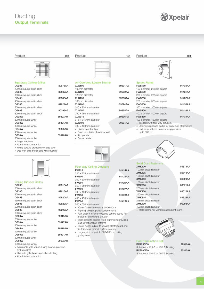
79
DuctingOutput Terminals
Product Ref
Spigot PlatesFWS150 91430AA150 diameter, 225mm squareFWS200 91431AA200 diameter, 225mm squareFWS250 91432AA250 diameter, 300mm squareFWS300 91456AA350 diameter, 300mm squareFWS400 91433AA400 diameter, 400mm squareFWS450 91434AA400 diameter, 450mm square� Interlock with four way diffusers� Sloping spigot and barbs for easy duct attachment� Built-in air volume damper in spigot sizes
up to 300mm
Solid Duct FastenersXMK100 89618AA100mm duct diameterXMK125 89619AA 125mm duct diameter XMK150 89620AA150mm duct diameterXMK200 89621AA200mm duct diameterXMK250 89622AA250mm duct diameterXMK315 89623AA315mm duct diameterXMK400 90293AA400mm duct diameter� Metal clamping, vibration absorbent foam
Roof Termination Set RC125/150 92311AA Suitable for 125 Ø or 150 Ø DuctingRC200/250 92312AASuitable for 200 Ø or 250 Ø Ducting
Product Ref
Air Operated Louvre Shutter XLG100 89691AA100mm diameterXLG120 89692AA120mm diameterXLG150 89693AA160mm diameterXLG200 89694AA200 x 200mm diameterXLG250 89695AA250 x 250mm diameter XLG315 89696AA315 x 315mm diameter XLG400 90294AA400 x 400mm diameter � Plastic construction� Fixed to outside of exterior wall� Air operated� Colour: white
Four Way Ceiling Diffusers FW225 91424AA225 x 225mm diameter FW300 91425AA 300 x 300mm diameter FW350 91426AA 350 x 350mm diameter FW400 91427AA400 x 400mm diameter FW450 91428AA450 x 450mm diameter FW500 91429AA500 x 500mm diameter* � *Outer frame dimensions 600x600mm � Rigid lightweight polypropylene frame� Four drop-in diffuser cassette can be set up for
angled or downward diffusion� Each cassette can be fitted eight ways providing
multi directional air patterns� Secret fixings adjust to varying plasterboard and
tile thickness without surface screws� Largest size drops into 600x600mm ceiling
grid system
Product Ref
Egg-crate Ceiling Grilles CG20S 89675AA 200mm square satin silverCG30S 89532AA300mm square satin silverCG45S 89533AA 450mm square satin silverCG50S 89827AA500mm square satin silverCG60S 90295AA600mm square satin silver CG20W 89823AW200mm square whiteCG30W 89824AW300mm square whiteCG45W 89825AW450mm square whiteCG50W 89826AW500mm square white � Large free area� Aluminium construction� Fixing screws provided (not size 600)� Use with grille boxes and Xflex ducting
Ceiling Diffuser Grilles DG20S 89816AA200mm square satin silverDG30S 89818AA 300mm square satin silverDG45S 89820AA 450mm square satin silverDG50S 89822AA500mm square satin silverDG60S 90292AA600mm square satin silver DG20W 89815AW200mm square whiteDG30W 89817AW300mm square whiteDG45W 89819AW450mm square whiteDG50W 89821AW500mm square whiteDG60W 90603AW600mm square white� Adjustable grille vanes. Fixing screws provided
(not size 600) � Use with grille boxes and Xflex ducting� Aluminium construction
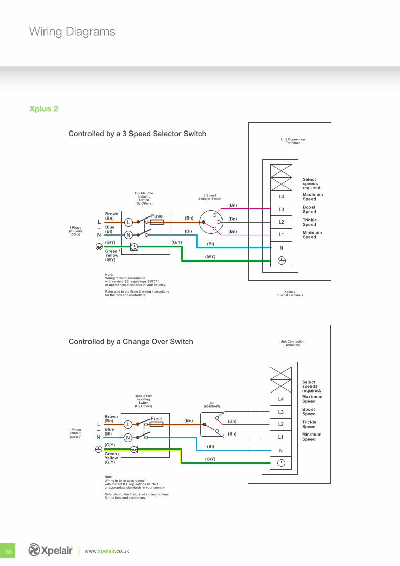
80 www.xpelair.co.uk
Wiring Diagrams
Xplus 2
Double PoleIsolatingSwitch
(By Others)
3 SpeedSelector Switch
1 Phase(230Vac)(50Hz)
FuseBrown(Bn)
Blue(Bl)
N
LL
N~
Green /Yellow(G/Y)
(G/Y)(G/Y)
(Bn)
(BI)
(BI)
Unit ConnectionTerminals
Note:Wiring to be in accordancewith current IEE regulations BS7671or appropriate standards in your country.
Refer also to the fiting & wiring instructionsfor the fans and controllers.
N
L4
L3
L2
L1
MaximumSpeed
Selectspeedsrequired:
BoostSpeed
TrickleSpeed
MinimumSpeed
(G/Y)
Xplus 2Internal Terminals
(Bn)
(Bn)
(Bn)
Controlled by a 3 Speed Selector Switch
Double PoleIsolatingSwitch
(By Others)COS
(90108AW)
1 Phase(230Vac)(50Hz)
FuseBrown(Bn)
Blue(Bl)
N
LL
N~
Green /Yellow(G/Y)
(G/Y)
(Bn)
(BI)
Unit ConnectionTerminals
Note:Wiring to be in accordancewith current IEE regulations BS7671or appropriate standards in your country.
Refer also to the fiting & wiring instructionsfor the fans and controllers.
N
L4
L3
L2
L1
MaximumSpeed
Selectspeedsrequired:
BoostSpeed
TrickleSpeed
MinimumSpeed
(G/Y)
(Bn)
(Bn)
Controlled by a Change Over Switch
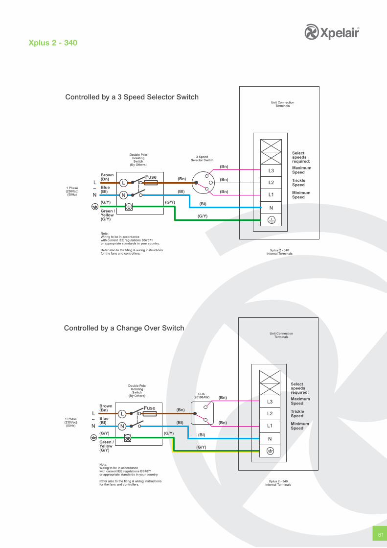
81
Double PoleIsolatingSwitch
(By Others)
3 SpeedSelector Switch
1 Phase(230Vac)(50Hz)
FuseBrown(Bn)
Blue(Bl)
N
LL
N~
Green /Yellow(G/Y)
(G/Y)(G/Y)
(Bn)
(BI)
(BI)
Unit ConnectionTerminals
Note:Wiring to be in accordancewith current IEE regulations BS7671or appropriate standards in your country.
Refer also to the fiting & wiring instructionsfor the fans and controllers.
N
L3
L2
L1
MaximumSpeed
Selectspeedsrequired:
TrickleSpeed
MinimumSpeed
(G/Y)
Xplus 2 - 340Internal Terminals
(Bn)
(Bn)
(Bn)
Controlled by a 3 Speed Selector Switch
Xplus 2 - 340
Double PoleIsolatingSwitch
(By Others)
1 Phase(230Vac)(50Hz)
FuseBrown(Bn)
Blue(Bl)
N
LL
N~
Green /Yellow(G/Y)
(G/Y)(G/Y)
(Bn)
(BI)
(BI)
Unit ConnectionTerminals
Note:Wiring to be in accordancewith current IEE regulations BS7671or appropriate standards in your country.
Refer also to the fiting & wiring instructionsfor the fans and controllers.
MaximumSpeed
Selectspeedsrequired:
TrickleSpeed
MinimumSpeed
(G/Y)
Xplus 2 - 340Internal Terminals
(Bn)
(Bn)
Controlled by a Change Over Switch
COS(90108AW)
N
L3
L2
L1
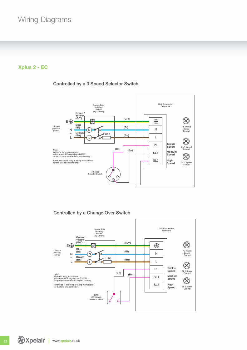
82 www.xpelair.co.uk
Wiring Diagrams
Xplus 2 - EC
Double PoleIsolatingSwitch
(By Others)
1 Phase(240Vac)(50Hz)
Fuse
Blue(Bl)
Brown(Bn)
Green /Yellow(G/Y)
L
N
L
N
COS(90108AW)
Selector Switch
N
L
PL
SL1
SL2
~
E(G/Y)
(BI)
(Bn)
(Bn)(Bn)
TrickleSpeed
MediumSpeed
HighSpeed
Unit ConnectionTerminals
PL TrickleSpeedControl
SL 1 SpeedControl
SL 2 SpeedControl
Note:Wiring to be in accordancewith current IEE regulations BS7671or appropriate standards in your country.
Refer also to the fiting & wiring instructionsfor the fans and controllers.
Controlled by a Change Over Switch
Double PoleIsolatingSwitch
(By Others)
1 Phase(240Vac)(50Hz)
Fuse
Blue(Bl)
Brown(Bn)
Green /Yellow(G/Y)
L
N
L
N
3 SpeedSelector Switch
N
L
PL
SL1
SL2
~
E(G/Y)
(BI)
(Bn)
(Bn)(Bn)
TrickleSpeed
MediumSpeed
HighSpeed
Unit ConnectionTerminals
PL TrickleSpeedControl
SL 1 SpeedControl
SL 2 SpeedControl
Note:Wiring to be in accordancewith current IEE regulations BS7671or appropriate standards in your country.
Refer also to the fiting & wiring instructionsfor the fans and controllers.
Controlled by a 3 Speed Selector Switch
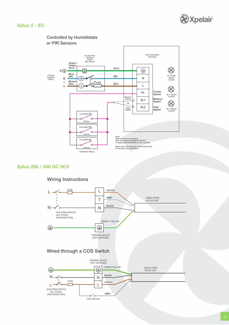
83
Double PoleIsolatingSwitch
(By Others)
1 Phase(240Vac)(50Hz)
Fuse
Blue(Bl)
Brown(Bn)
Green /Yellow(G/Y)
L
N
L
N N
L
PL
SL1
SL2
~
E(G/Y)
(BI)
(Bn)
TrickleSpeed
MediumSpeed
HighSpeed
Unit ConnectionTerminals
PL TrickleSpeedControl
SL 1 SpeedControl
SL 2 SpeedControl
Note:Wiring to be in accordancewith current IEE regulations BS7671or appropriate standards in your country.
Refer also to the fiting & wiring instructionsfor the fans and controllers.
Controlled by Humidistatsor PIR Sensors
Low Speed
Sensor
Low Speed
Sensor
Low Speed
Sensor
Or
MediumSpeed
HighSpeed
Installation Wiring
Xplus 2 - EC
BLACK
GREY
Wiring Instructions
Wired through a COS Switch
GREY
BLACK
Xplus 250 / 400 DC 8CV
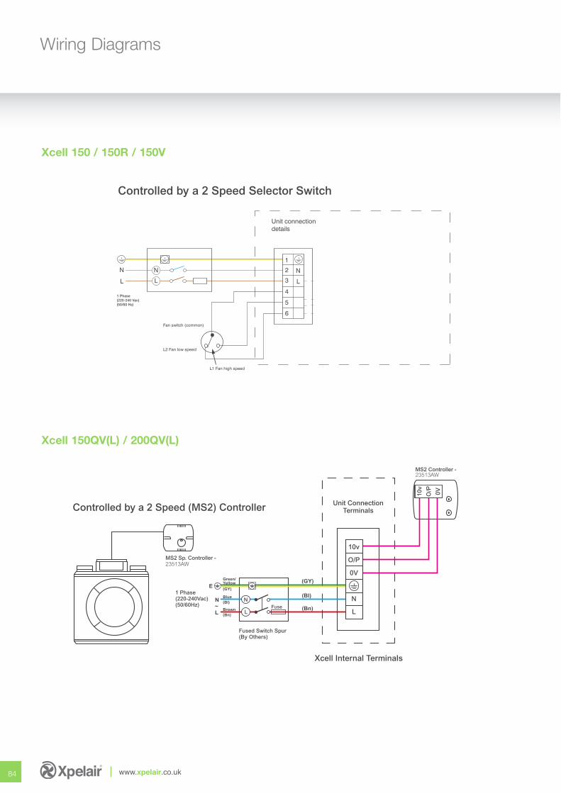
84 www.xpelair.co.uk
Wiring Diagrams
Xcell 150 / 150R / 150V
Controlled by a 2 Speed Selector Switch
MS2 Sp. Controller - 23513AW
Unit ConnectionTerminals
Xcell Internal Terminals
MS2 Controller - 23513AW
Fuse
Fused Switch Spur(By Others)
1 Phase(220-240Vac)(50/60Hz)
10v
O/P 0V
N
L
10v
O/P
0V
N
L
Green/Yellow
(GY)
Blue(Bl)
Brown(Bn)
(GY)
(Bl)
(Bn)
E
N
L~
Controlled by a 2 Speed (MS2) Controller
Xcell 150QV(L) / 200QV(L)
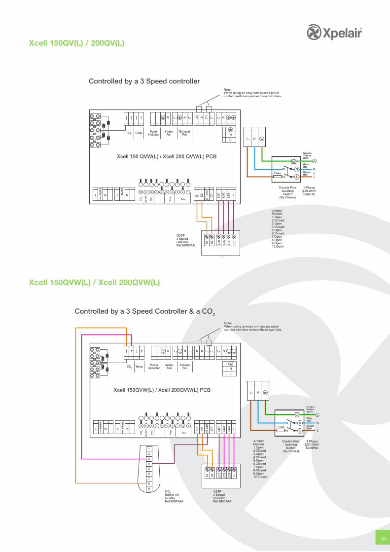
85
Xcell 150QV(L) / 200QV(L)
Xcell 150 QVW(L) / Xcell 200 QVW(L) PCB
Temp PowerIndicator
IntakeFan
ExhaustFan
T T N N N N NL1L1L1L1L1
T TN NPW
M
PW
M
10 9 8 7 6 5 4 3 2 1
CO
2
ON
-OFF
BD
E
Tem
p
Type
CO2
S1
S2
OT
24V
OT
LD1
LD2
LD3 T
Note:When using an easy turn access panelcontact switches remove these two links.
Q3SP3 SpeedSelectorRef.96005AA
Fuse
Blue(Bl)
Brown(Bn)
Green /Yellow(G/Y)
L
N
L
N
Double PoleIsolatingSwitch
(By Others)
1 Phase(220-240V50/60Hz)
JumperPostion1.Open2.Closed3.Open4.Closed5.Open6.Closed7.Open8.Open9.Open10.Open
L1 N
~
N
L1
Controlled by a 3 Speed controller
S1
S2
LD1
LD2
LD3 T
Xcell 150QVW(L) / Xcell 200QVW(L)
Xcell 150QVW(L) / Xcell 200QVW(L) PCB
Temp PowerIndicator
IntakeFan
ExhaustFan
T T N N N N NL1L1L1L1L1
T TN NPW
M
PW
M
10 9 8 7 6 5 4 3 2 1
CO
2
ON
-OFF
BD
E
Tem
p
Type
N
L1
1
2
3
4
5
6
7
8
9
CO2
S1
S2
LD1
LD2
LD3 T
S1
S2
OT
24V
OT
LD1
LD2
LD3 T Fuse
Blue(Bl)
Brown(Bn)
Green /Yellow(G/Y)
L
N
L
N
Double PoleIsolatingSwitch
(By Others)
1 Phase(220-240V50/60Hz)
JumperPostion1.Open2.Closed3.Open4.Closed5.Open6.Closed7.Open8.Closed9.Open10.Closed
L1 N
Note:When using an easy turn access panelcontact switches remove these two links.
Q3SP3 SpeedSelectorRef.96005AA
CO2Indoor AirQualityRef.96003AA
~
Controlled by a 3 Speed Controller & a CO2
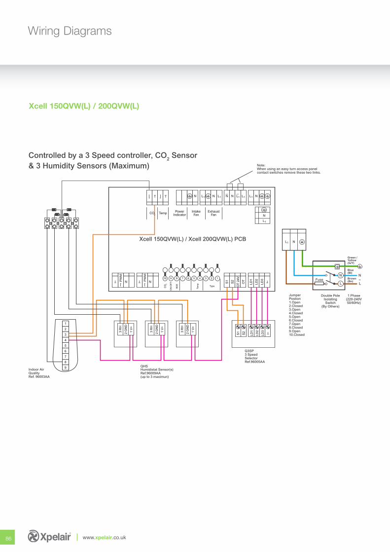
86 www.xpelair.co.uk
Wiring Diagrams
Xcell 150QVW(L) / Xcell 200QVW(L) PCB
Temp PowerIndicator
IntakeFan
ExhaustFan
T T N N N N NL1L1L1L1L1
T TN NPW
M
PW
M
10 9 8 7 6 5 4 3 2 1
CO
2
ON
-OFF
BD
E
Tem
p
Type
N
L1
1
2
3
4
5
6
7
8
9
CO2
3 R
H
2 G
ND
1 V
+
3 R
H
2 G
ND
1 V
+
3 R
H
2 G
ND
1 V
+
S1
S2
LD1
LD2
LD3 T
S1
S2
OT
24V
OT
LD1
LD2
LD3 T Fuse
Blue(Bl)
Brown(Bn)
Green /Yellow(G/Y)
L
N
L
N
Double PoleIsolatingSwitch
(By Others)
1 Phase(220-240V50/60Hz)
JumperPostion1.Open2.Closed3.Open4.Closed5.Open6.Closed7.Open8.Closed9.Open10.Closed
L1 N
Note:When using an easy turn access panelcontact switches remove these two links.
Indoor AirQualityRef. 96003AA
QHSHumidistat Sensor(s)Ref.96009AA(up to 3 maximun)
Q3SP3 SpeedSelectorRef.96005AA
~
Controlled by a 3 Speed controller, CO2 Sensor& 3 Humidity Sensors (Maximum)
Xcell 150QVW(L) / 200QVW(L)
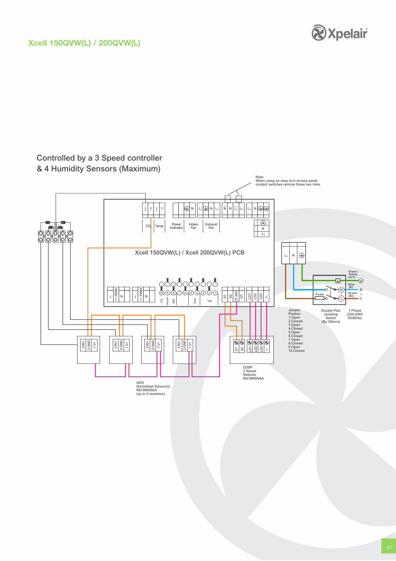
87
Xcell 150QVW(L) / Xcell 200QVW(L) PCB
Temp PowerIndicator
IntakeFan
ExhaustFan
T T N N N N NL1L1L1L1L1
T TN NPW
M
PW
M
10 9 8 7 6 5 4 3 2 1
CO
2
ON
-OFF
BD
E
Tem
p
Type
N
L1
CO2
3 R
H
2 G
ND
1 V
+
3 R
H
2 G
ND
1 V
+
3 R
H
2 G
ND
1 V
+
3 R
H
2 G
ND
1 V
+
S1
S2
LD1
LD2
LD3 T
S1
S2
OT
24V
OT
LD1
LD2
LD3 T Fuse
Blue(Bl)
Brown(Bn)
Green /Yellow(G/Y)
L
N
L
N
Double PoleIsolatingSwitch
(By Others)
1 Phase(220-240V50/60Hz)
JumperPostion1.Open2.Closed3.Open4.Closed5.Open6.Closed7.Open8.Closed9.Open10.Closed
L1 N
Note:When using an easy turn access panelcontact switches remove these two links.
QHSHumidistat Sensor(s)Ref.96009AA(up to 4 maximun)
Q3SP3 SpeedSelectorRef.96005AA
~
Controlled by a 3 Speed controller& 4 Humidity Sensors (Maximum)
Xcell 150QVW(L) / 200QVW(L)
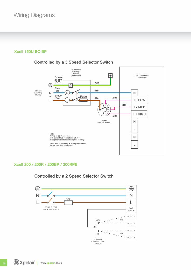
88 www.xpelair.co.uk
Wiring Diagrams
Xcell 200 / 200R / 200BP / 200RPB
Controlled by a 2 Speed Selector Switch
Xcell 150U EC BP
Double PoleIsolatingSwitch
(By Others)
1 Phase(230Vac)(50Hz)
3 SpeedSelector Switch
Fuse
Blue(Bl)
Brown(Bn)
Green /Yellow(G/Y)
L
N
L
N~
(G/Y)
(BI)
(Bn) (Bn)
(Bn)
Unit ConnectionTerminals
Note:Wiring to be in accordancewith current IEE regulations BS7671or appropriate standards in your country.
Refer also to the fiting & wiring instructionsfor the fans and controllers.
N
L3 LOW
L2 MED
L1 HIGH
N
L
N
L
L
H
M
(Bn)
Controlled by a 3 Speed Selector Switch
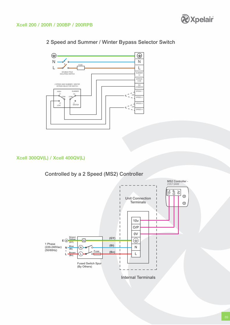
89
Xcell 200 / 200R / 200BP / 200RPB
Unit ConnectionTerminals
Internal Terminals
Controlled by a 2 Speed (MS2) ControllerMS2 Controller - 23513AW
Fuse
Fused Switch Spur(By Others)
1 Phase(220-240Vac)(50/60Hz)
10v
O/P 0V
N
L
10v
O/P
0V
N
L
Green/Yellow
(GY)
Blue(Bl)
Brown(Bn)
(GY)
(Bl)
(Bn)
E
N
L~
2 Speed and Summer / Winter Bypass Selector Switch
Xcell 300QV(L) / Xcell 400QV(L)
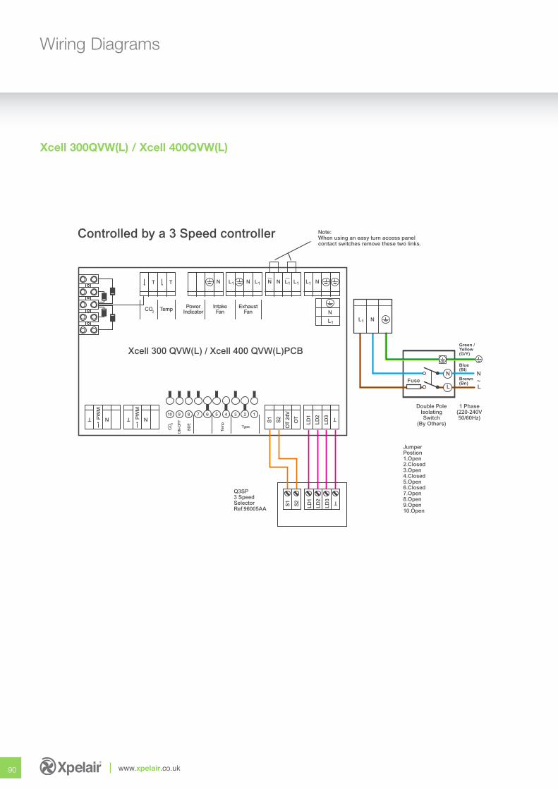
90 www.xpelair.co.uk
Wiring Diagrams
Xcell 300 QVW(L) / Xcell 400 QVW(L)PCB
Temp PowerIndicator
IntakeFan
ExhaustFan
T T N N N N NL1L1L1L1L1
T TN NPW
M
PW
M
10 9 8 7 6 5 4 3 2 1
CO
2
ON
-OFF
BD
E
Tem
p
Type
CO2
S1
S2
OT
24V
OT
LD1
LD2
LD3 T
Note:When using an easy turn access panelcontact switches remove these two links.
Q3SP3 SpeedSelectorRef.96005AA
Fuse
Blue(Bl)
Brown(Bn)
Green /Yellow(G/Y)
L
N
L
N
Double PoleIsolatingSwitch
(By Others)
1 Phase(220-240V50/60Hz)
JumperPostion1.Open2.Closed3.Open4.Closed5.Open6.Closed7.Open8.Open9.Open10.Open
L1 N
~
N
L1
Controlled by a 3 Speed controller
S1
S2
LD1
LD2
LD3 T
Xcell 300QVW(L) / Xcell 400QVW(L)
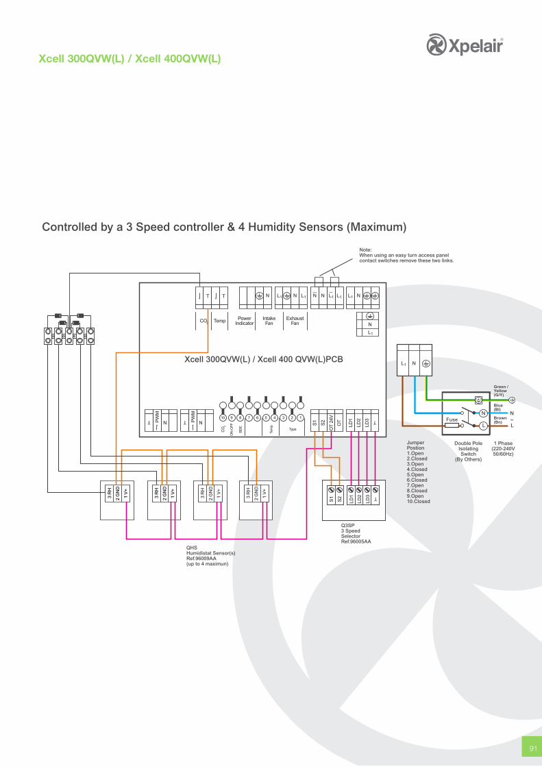
91
3 R
H
2 G
ND
1 V
+
3 R
H
2 G
ND
1 V
+
Xcell 300QVW(L) / Xcell 400 QVW(L)PCB
Temp PowerIndicator
IntakeFan
ExhaustFan
T T N N N N NL1L1L1L1L1
T TN NPW
M
PW
M
10 9 8 7 6 5 4 3 2 1
CO
2
ON
-OFF
BD
E
Tem
p
Type
N
L1
CO2
3 R
H
2 G
ND
1 V
+
3 R
H
2 G
ND
1 V
+
S1
S2
LD1
LD2
LD3 T
S1
S2
OT
24V
OT
LD1
LD2
LD3 T Fuse
Blue(Bl)
Brown(Bn)
Green /Yellow(G/Y)
L
N
L
N
Double PoleIsolatingSwitch
(By Others)
1 Phase(220-240V50/60Hz)
JumperPostion1.Open2.Closed3.Open4.Closed5.Open6.Closed7.Open8.Closed9.Open10.Closed
L1 N
Note:When using an easy turn access panelcontact switches remove these two links.
QHSHumidistat Sensor(s)Ref.96009AA(up to 4 maximun)
Q3SP3 SpeedSelectorRef.96005AA
~
Controlled by a 3 Speed controller & 4 Humidity Sensors (Maximum)
Xcell 300QVW(L) / Xcell 400QVW(L)
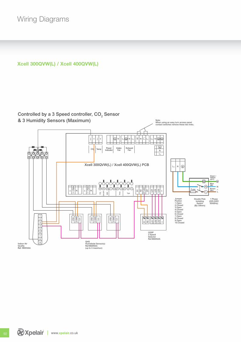
92 www.xpelair.co.uk
Wiring Diagrams
Xcell 300QVW(L) / Xcell 400QVW(L)
Xcell 300QVW(L) / Xcell 400QVW(L) PCB
Temp PowerIndicator
IntakeFan
ExhaustFan
T T N N N N NL1L1L1L1L1
T TN NPW
M
PW
M
10 9 8 7 6 5 4 3 2 1
CO
2
ON
-OFF
BD
E
Tem
p
Type
N
L1
1
2
3
4
5
6
7
8
9
CO2
3 R
H
2 G
ND
1 V
+
3 R
H
2 G
ND
1 V
+
3 R
H
2 G
ND
1 V
+
S1
S2
LD1
LD2
LD3 T
S1
S2
OT
24V
OT
LD1
LD2
LD3 T Fuse
Blue(Bl)
Brown(Bn)
Green /Yellow(G/Y)
L
N
L
N
Double PoleIsolatingSwitch
(By Others)
1 Phase(220-240V50/60Hz)
JumperPostion1.Open2.Closed3.Open4.Closed5.Open6.Closed7.Open8.Closed9.Open10.Closed
L1 N
Note:When using an easy turn access panelcontact switches remove these two links.
Indoor AirQualityRef. 96003AA
QHSHumidistat Sensor(s)Ref.96009AA(up to 3 maximun)
Q3SP3 SpeedSelectorRef.96005AA
~
Controlled by a 3 Speed controller, CO2 Sensor& 3 Humidity Sensors (Maximum)
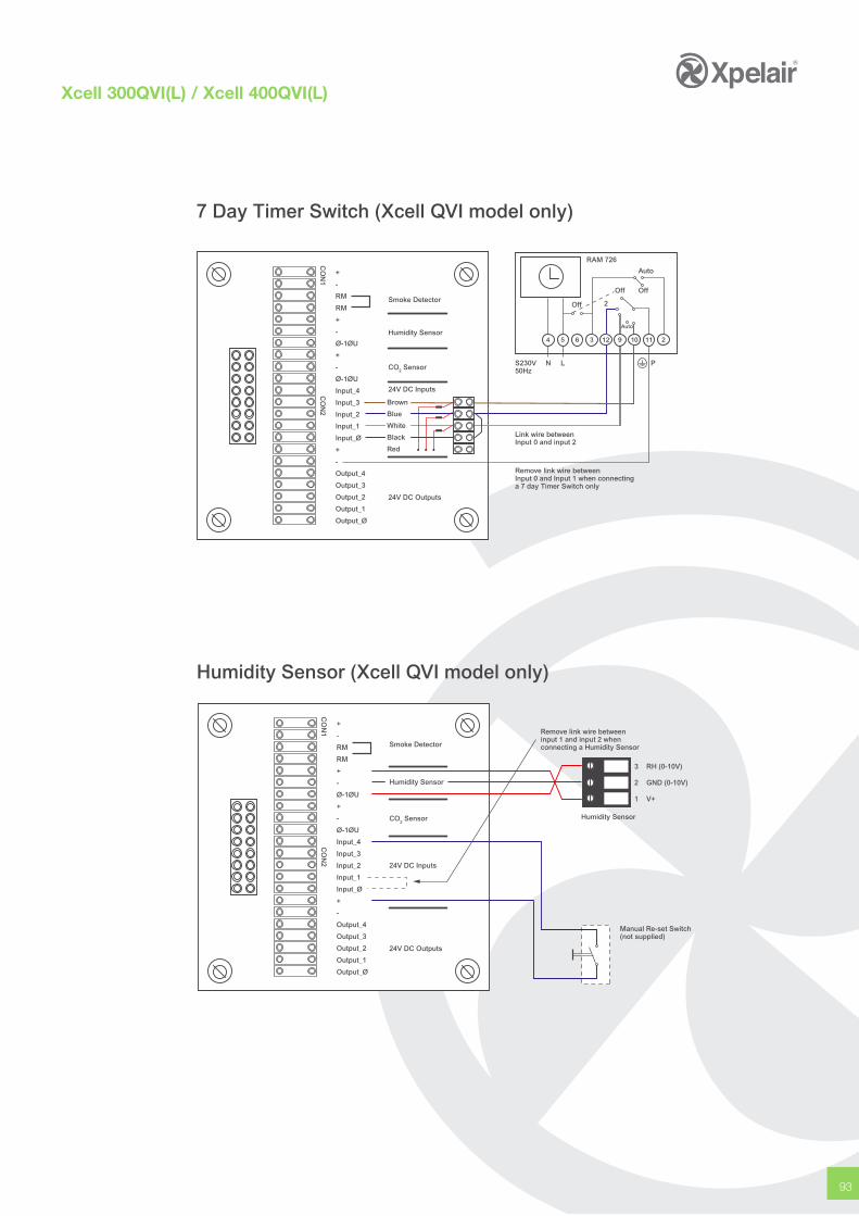
93
Xcell 300QVI(L) / Xcell 400QVI(L)
Smoke Detector
Humidity Sensor
24V DC Inputs
CO2 Sensor
24V DC Outputs
CO
N1
CO
N2
+
-
RM
RM
+
-
Ø-1ØU
+
-
Ø-1ØU
Input_4
Input_3
Input_2
Input_1
Input_Ø
+
-
Output_4
Output_3
Output_2
Output_1
Output_Ø
Link wire betweenInput 0 and input 2
Remove link wire betweenInput 0 and Input 1 when connectinga 7 day Timer Switch only
S230V50Hz
N L P
64 5 3 12 9 210
RAM 726
Auto
OffOff
11
Off 2
Auto
Brown
Blue
White
Black
Red
7 Day Timer Switch (Xcell QVI model only)
Smoke Detector
Humidity Sensor
24V DC Inputs
24V DC Outputs
CO
N1
CO
N2
+
-
RM
RM
+
-
Ø-1ØU
+
-
Ø-1ØU
Input_4
Input_3
Input_2
Input_1
Input_Ø
+
-
Output_4
Output_3
Output_2
Output_1
Output_Ø
Manual Re-set Switch(not supplied)
3
2
1
RH (0-10V)
GND (0-10V)
V+
Humidity SensorCO2 Sensor
Remove link wire betweeninput 1 and input 2 whenconnecting a Humidity Sensor
Humidity Sensor (Xcell QVI model only)
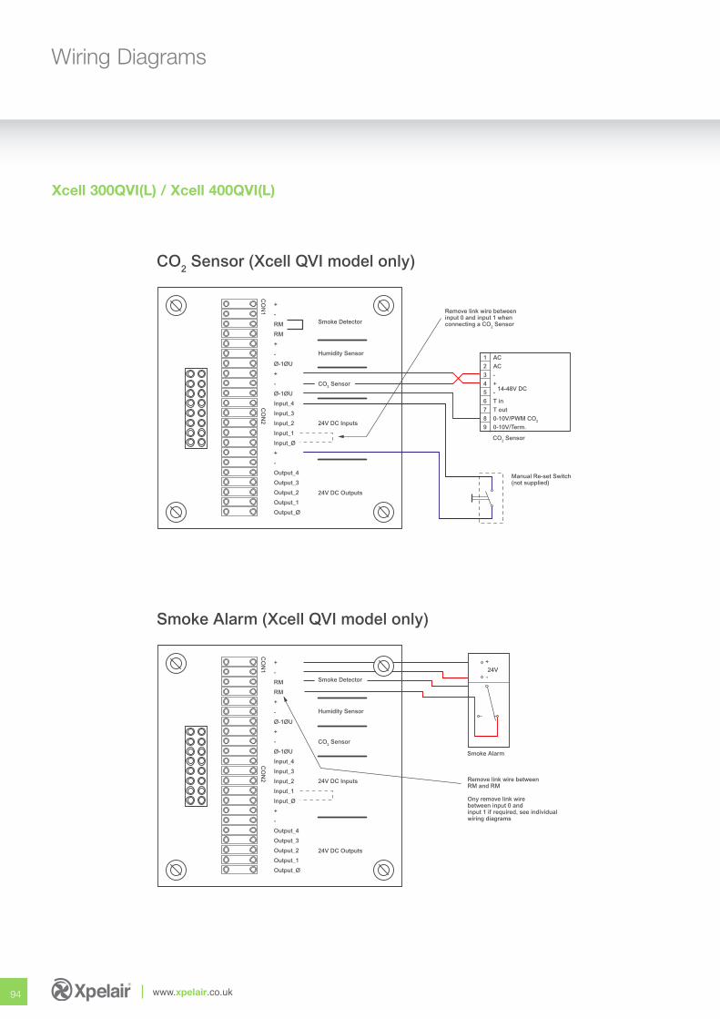
94 www.xpelair.co.uk
Wiring Diagrams
Xcell 300QVI(L) / Xcell 400QVI(L)
Smoke Detector
Humidity Sensor
24V DC Inputs
24V DC Outputs
CO
N1
CO
N2
+
-
RM
RM
+
-
Ø-1ØU
+
-
Ø-1ØU
Input_4
Input_3
Input_2
Input_1
Input_Ø
+
-
Output_4
Output_3
Output_2
Output_1
Output_Ø
Manual Re-set Switch(not supplied)
1
2
3
4
5
6
7
8
9
AC
AC
-
+
-
T in
T out
0-10V/PWM CO2
0-10V/Term.
CO2 Sensor
14-48V DCCO2 Sensor
Remove link wire betweeninput 0 and input 1 whenconnecting a CO2 Sensor
CO2 Sensor (Xcell QVI model only)
Smoke Detector
Humidity Sensor
24V DC Inputs
24V DC Outputs
CO
N1
CO
N2
+
-
RM
RM
+
-
Ø-1ØU
+
-
Ø-1ØU
Input_4
Input_3
Input_2
Input_1
Input_Ø
+
-
Output_4
Output_3
Output_2
Output_1
Output_Ø
Smoke Alarm
CO2 Sensor
Remove link wire betweenRM and RM
Ony remove link wirebetween input 0 andinput 1 if required, see individualwiring diagrams
+
-24V
Smoke Alarm (Xcell QVI model only)
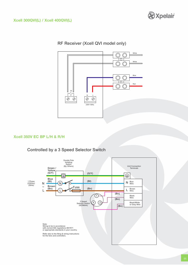
95
Xcell 300QVI(L) / Xcell 400QVI(L)
Xcell 350V EC BP L/H & R/H
Double PoleIsolatingSwitch
(By Others)
1 Phase(230Vac)(50Hz)
3 SpeedSelector Switch
(92396AA)
Fuse
Blue(Bl)
Brown(Bn)
Green /Yellow(G/Y)
L
N
L
N~
(G/Y)
(BI)
(Bn)
(Bn)
Unit ConnectionTerminals
Note:Wiring to be in accordancewith current IEE regulations BS7671or appropriate standards in your country.
Refer also to the fiting & wiring instructionsfor the fans and controllers.
N
L
1
24
(Bn)
(Bn)
Controlled by a 3 Speed Selector Switch
BrownWire
BlackWire
Black/Whiteor Grey Wire
BlueWire
White
White
Blue
Red
3A
N L
230V~50Hz
RF Receiver (Xcell QVI model only)
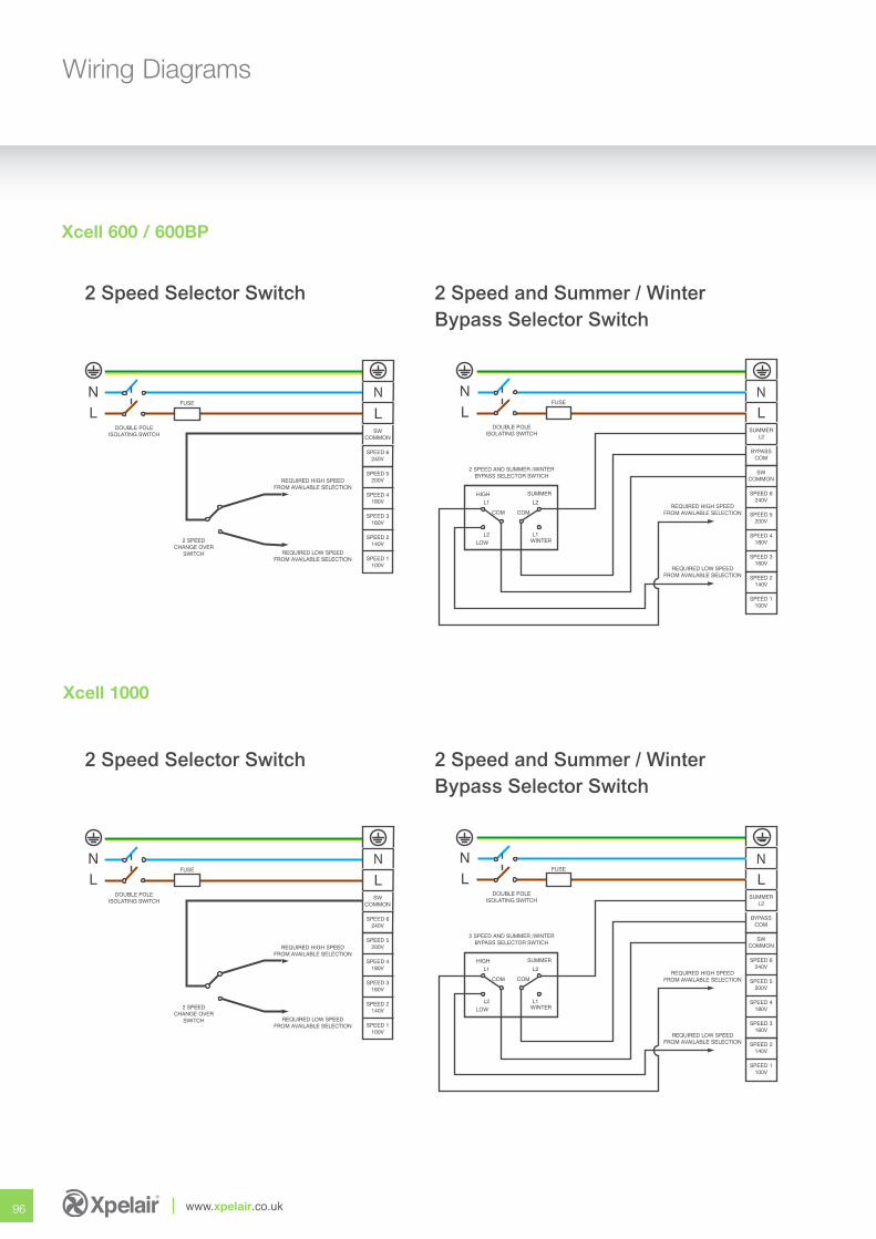
96 www.xpelair.co.uk
Wiring Diagrams
Xcell 1000
2 Speed Selector Switch 2 Speed and Summer / WinterBypass Selector Switch
Xcell 600 / 600BP
2 Speed Selector Switch 2 Speed and Summer / WinterBypass Selector Switch
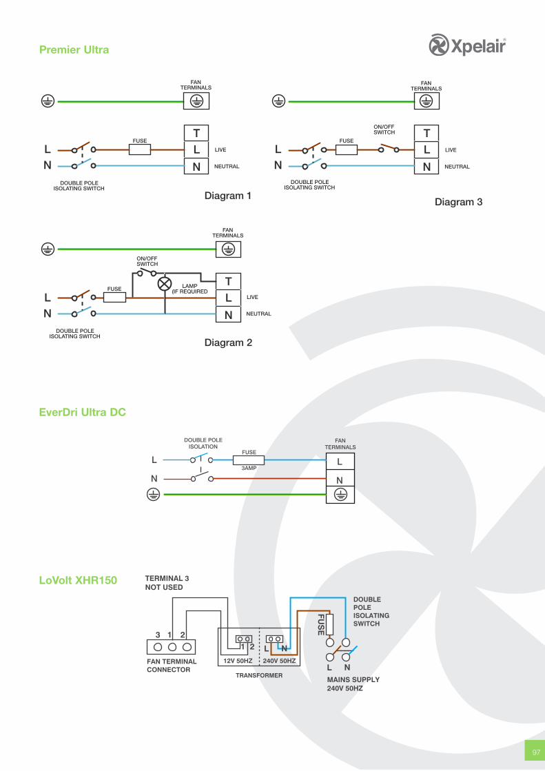
97
DOUBLE POLEISOLATING SWITCH
DOUBLE POLEISOLATING SWITCH
DOUBLE POLEISOLATING SWITCH
LIVE
NEUTRAL
LIVE
NEUTRAL
LIVE
NEUTRAL
Diagram 1
Diagram 2
Diagram 3
FANTERMINALS
FANTERMINALS
FANTERMINALS
FUSE
FUSE
FUSE
ON/OFFSWITCH
ON/OFFSWITCH
LAMP(IF REQUIRED
LN
LN
LN
LT
N
LT
N
LT
N
Premier Ultra
LoVolt XHR150
EverDri Ultra DC
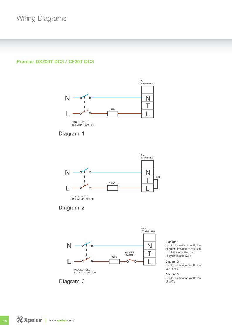
98 www.xpelair.co.uk
Wiring Diagrams
Premier DX200T DC3 / CF20T DC3
Diagram 1
Diagram 2
Diagram 3
NTL
N
L
FANTERMINALS
DOUBLE POLEISOLATING SWITCH
FUSE
ON/OFFSWITCH
LINKNTL
N
L
FANTERMINALS
DOUBLE POLEISOLATING SWITCH
FUSE
NTL
N
L
FANTERMINALS
DOUBLE POLEISOLATING SWITCH
FUSE
Diagram 1Use for intermittent ventilationof bathrooms and continuousventilation of bathrooms,utility room and WC’s
Diagram 2Use for continuous ventilationof kitchens
Diagram 3Use for continuous ventilationof WC’s
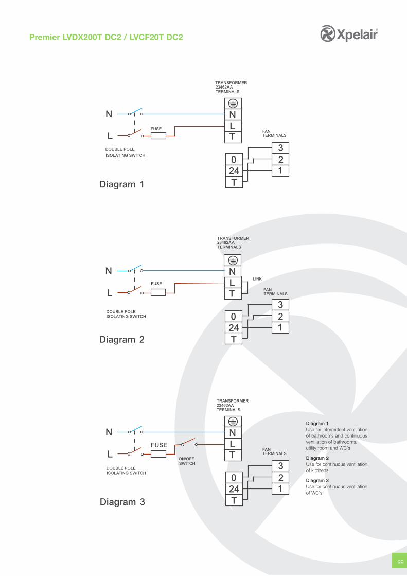
99
Premier LVDX200T DC2 / LVCF20T DC2
Diagram 1Use for intermittent ventilationof bathrooms and continuousventilation of bathrooms,utility room and WC’s
Diagram 2Use for continuous ventilationof kitchens
Diagram 3Use for continuous ventilationof WC’s
TRANSFORMER23462AATERMINALS
N
0
LN
LDOUBLE POLE
ISOLATING SWITCH
FUSE
24T
3T
12
FANTERMINALS
TRANSFORMER23462AATERMINALS
N
0
LN
L
DOUBLE POLEISOLATING SWITCH
FUSE
24T
3T
12
FANTERMINALS
TRANSFORMER23462AATERMINALS
N
0
LN
LDOUBLE POLEISOLATING SWITCH
FUSE
24T
3T
12
FANTERMINALS
Diagram 1
Diagram 2
Diagram 3
LINK
ON/OFFSWITCH

Morley WayPeterborough PE2 9JJUnited Kingdom
Tel: +44 (0)844 372 7761Fax: +44 (0)844 372 7762Web: www.xpelair.co.uk
X081 01/02/2010