Embed Size (px)
Citation preview
T-PAL. Transforaminal PosteriorAtraumatic Lumbar Cage System.
Technique Guide
This publication is not intended fordistribution in the USA.
Instruments and implants approved by the AO Foundation.

Image intensifier control
WarningThis description alone does not provide sufficient background for direct use ofthe instrument set. Instruction by a surgeon experienced in handling theseinstruments is highly recommended.
Reprocessing, Care and Maintenance of Synthes InstrumentsFor general guidelines, function control and dismantling of multi-part instruments,please refer to: www.synthes.com/reprocessing
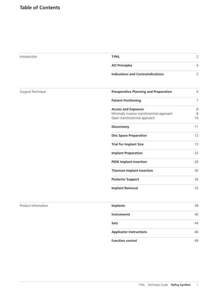
Table of Contents
Introduction
Surgical Technique
Product Information
T-PAL 2
AO Principles 4
Indications and Contraindications 5
Preoperative Planning and Preparation 6
Patient Positioning 7
Access and Exposure 8Minimally invasive transforaminal approach 8Open transforaminal approach 10
Discectomy 11
Disc Space Preparation 12
Trial for Implant Size 13
Implant Preparation 23
PEEK Implant Insertion 26
Titanium Implant Insertion 30
Posterior Support 34
Implant Removal 35
Implants 38
Instruments 40
Sets 44
Applicator Instructions 46
Function control 49
T-PAL Technique Guide DePuy Synthes 1
– Rails on top of the implant, guide and turn the cage between the vertebral bodies into the desired position
– Three x-ray markers help to visualize the implant under radiographic control
T-PAL. Transforaminal PosteriorAtraumatic Lumbar Cage System.
Implant with guiding rails
MaterialAvailable in two materials; PEEK (with Titanium alloy marker pins [TAN]); Titanium alloy (TAN)
Two anterior radiographic marker pinsEnable visualization of the anterior implant positionThe B 1.4 pins are located approximately 2.0 mm from the anterior edge of the implant
One proximal radiographic marker pinEnable visualization of implant tip position whileinsertion
Connection cylinderPermits the pivoting mechanism in combination with the applicator
Axial windowAccommodates autogenous bone graft or bone graft substitute to allow fusion to occur through the cage
Rails on the surfaceGuide and turn the cage into the desired position
Pyramidal teethProvide resistance to implant migration
Self-distracting noseAllows for ease of insertion
Lordotic angle5° to restore the natural spine lordotic curve (except for the 7 mm height)
2 DePuy Synthes T-PAL Technique Guide
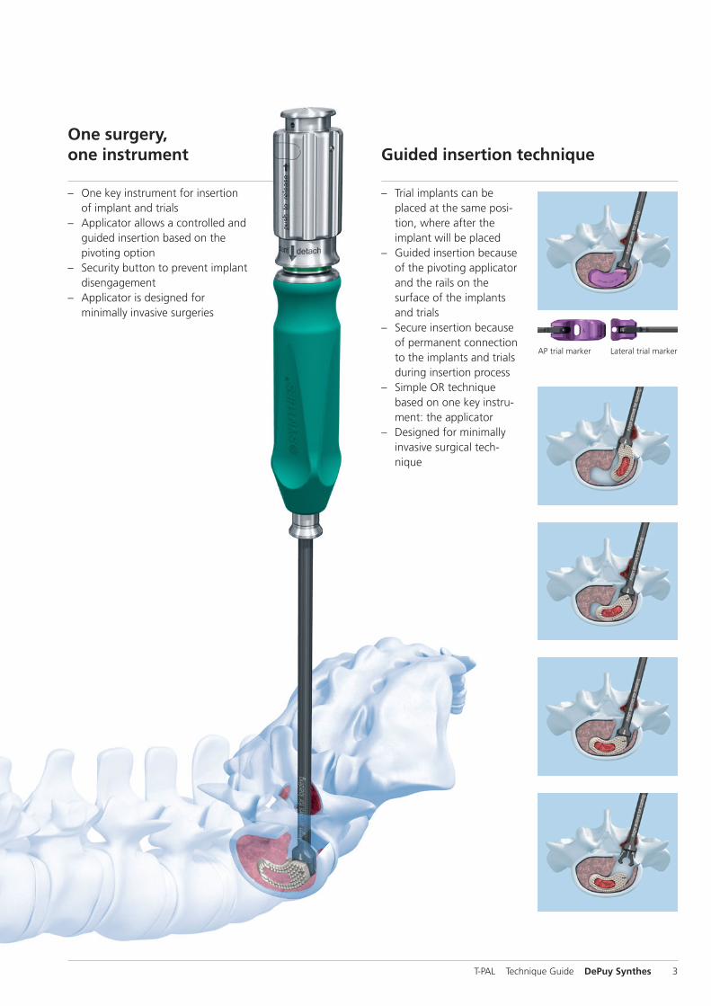
– Trial implants can beplaced at the same posi-tion, where after the implant will be placed
– Guided insertion becauseof the pivoting applicatorand the rails on the surface of the implantsand trials
– Secure insertion becauseof permanent connectionto the implants and trialsduring insertion process
– Simple OR techniquebased on one key instru-ment: the applicator
– Designed for minimallyinvasive surgical tech-nique
Guided insertion technique
– One key instrument for insertionof implant and trials
– Applicator allows a controlled andguided insertion based on the pivoting option
– Security button to prevent implantdisengagement
– Applicator is designed for minimally invasive surgeries
One surgery,one instrument
AP trial marker Lateral trial marker
T-PAL Technique Guide DePuy Synthes 3
AO Principles
1Müller ME, Allgöwer M, Schneider R, Willenegger H (1995) Manual of Internal Fixation. 3rd, expanded and completely revised ed. 1991. Berlin,Heidelberg, New York: Springer
2Aebi M, Arlet V, Webb JK (2007). AOSpine Manual (2 vols), Stuttgart, New York:Thieme
In 1958, the AO formulated four basic principles1, whichhave become the guidelines for internal fixation. They are:– Anatomical reduction– Stable internal fixation– Preservation of blood supply– Early, active pain-free mobilization
The fundamental aims of fracture treatment in the limbsand fusion of the spine are the same. A specific goal in thespine is returning as much function as possible to theinjured neural elements.2
AO Principles as applied to the Spine2
Anatomical reductionRestoration of normal spinal alignment to improve the biomechanics of the spine.
Stable internal fixationStabilization of the spinal segment to promote bony fusion.
Preservation of blood supplyCreation of an optimal environment for fusion.
Early, active pain-free mobilizationMinimization of damage to the spinal vasculature, dura, andneural elements, which may contribute to pain reduction andimproved function for the patient.
4 DePuy Synthes T-PAL Technique Guide
Indications and Contraindications
Intended useThe T-PAL implant is intended to replace lumbar interverte-bral discs and to fuse the adjacent vertebral bodies togetherat vertebral levels L1–S1. The T-PAL implant is designed fora transforaminal approach.
IndicationsIndications are lumbar and lubosacral pathologies in whichsegmental spondylodesis is indicated, for example:– Degenerative disc diseases and spinal instabilities– Revision procedures for post-discectomy syndrome– Pseudarthrosis or failed spondylodesis– Degenerative spondylolisthesis– Isthmic spondylolisthesis
Contraindications– Vertebral body fractures– Spinal tumours– Major spinal instabilities– Primary spinal deformities– Osteoporosis
Important: T-PAL must be applied in combination with posterior fixation.
T-PAL Technique Guide DePuy Synthes 5
Preparation
Set
01.812.001 Set T-PAL
Optional sets
01.809.011 Dilation Instrument Set
01.615.004 Insight Tube Set, Standard Configurationor01.615.002 Insight Retractor Set, Standard Configuration
01.612.100 Set for MIS Support System
01.605.903 Set for Minimally Invasive Posterior Instruments
Have all necessary imaging studies readily available to planimplant placement and visualize individual patient anatomy.
Have all sets readily available prior to surgery.
Preoperative Planning and Preparation
6 DePuy Synthes T-PAL Technique Guide
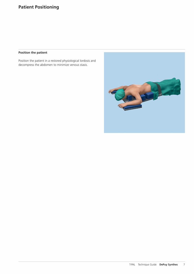
Position the patient
Position the patient in a restored physiological lordosis anddecompress the abdomen to minimize venous stasis.
Patient Positioning
T-PAL Technique Guide DePuy Synthes 7
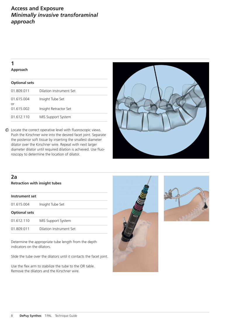
1Approach
Optional sets
01.809.011 Dilation Instrument Set
01.615.004 Insight Tube Setor01.615.002 Insight Retractor Set
01.612.110 MIS Support System
Locate the correct operative level with fluoroscopic views.Push the Kirschner wire into the desired facet joint. Separatethe posterior soft tissue by inserting the smallest diameterdilator over the Kirschner wire. Repeat with next larger diameter dilator until required dilation is achieved. Use fluo-roscopy to determine the location of dilator.
Access and Exposure Minimally invasive transforaminalapproach
2aRetraction with insight tubes
Instrument set
01.615.004 Insight Tube Set
Optional sets
01.612.110 MIS Support System
01.809.011 Dilation Instrument Set
Determine the appropriate tube length from the depth indicators on the dilators.
Slide the tube over the dilators until it contacts the facet joint.
Use the flex arm to stabilize the tube to the OR table. Remove the dilators and the Kirschner wire.
8 DePuy Synthes T-PAL Technique Guide
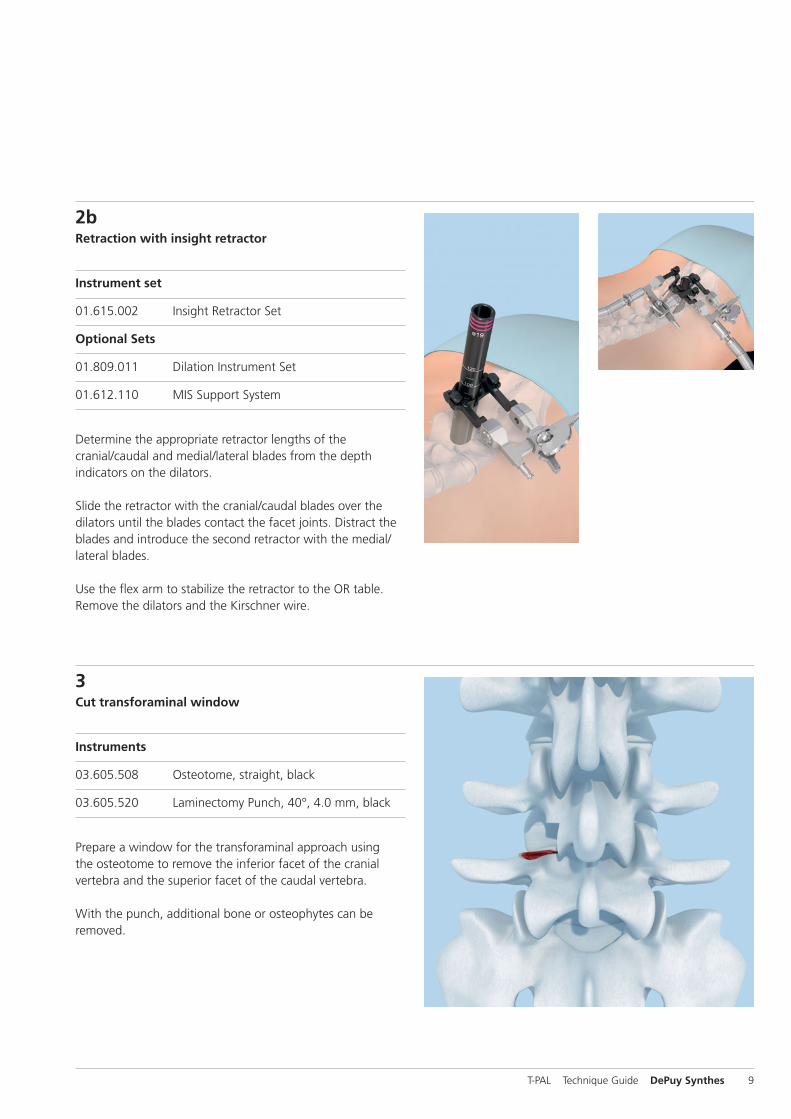
2bRetraction with insight retractor
Instrument set
01.615.002 Insight Retractor Set
Optional Sets
01.809.011 Dilation Instrument Set
01.612.110 MIS Support System
Determine the appropriate retractor lengths of thecranial/caudal and medial/lateral blades from the depth indicators on the dilators.
Slide the retractor with the cranial/caudal blades over thedilators until the blades contact the facet joints. Distract theblades and introduce the second retractor with the medial/lateral blades.
Use the flex arm to stabilize the retractor to the OR table. Remove the dilators and the Kirschner wire.
3Cut transforaminal window
Instruments
03.605.508 Osteotome, straight, black
03.605.520 Laminectomy Punch, 40°, 4.0 mm, black
Prepare a window for the transforaminal approach usingthe osteotome to remove the inferior facet of the cranial vertebra and the superior facet of the caudal vertebra.
With the punch, additional bone or osteophytes can be removed.
T-PAL Technique Guide DePuy Synthes 9

1Retraction with an open transforaminal approach
Instrument
03.812.040 Lamina Spreader for T-PAL
Make a standard open incision, retract the muscle layer toview the desired segment.
Distract the segment if desired. Position the lamina spreaderfor T-PAL at the base of the spinous processes. Distract carefully until required distraction is achieved.
Distraction opens the posterior disc space and promotes exposure both for decompression and delivery of the implant.
2Cut transforaminal window
Instruments
03.605.508 Osteotome, straight, black
03.605.520 Laminectomy Punch, 40°, 4.0 mm, black
Prepare a window for the transforaminal approach usingthe osteotome to remove the inferior facet of the cranial vertebra and the superior facet of the caudal vertebra.
With the laminectomy punch, additional bone or osteophytes can be removed.
Access and Exposure Open transforaminal approach
10 DePuy Synthes T-PAL Technique Guide
Instruments
03.605.507 Rasp, dual-sided, bayoneted, black
03.605.510 Ring Curette, straight, bayoneted, black
03.605.514 Rongeur, curved, 4.0 mm, black
03.605.520 Laminectomy Punch, 40°, 4.0 mm, black
03.605.527 Rongeur, straight, 4.0 mm, black
03.605.529 Curette, rectangular, angled, right, bayoneted, black
03.605.530 Curette, rectangular, angled, left, bayoneted, black
03.803.054 Curette, rectangular, bayoneted, black
389.767 – Shaver for Intervertebral Discs, 389.777 size 7–17 mm
394.951 T-Handle with Quick Coupling
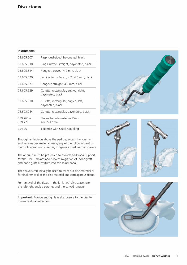
Through an incision above the pedicle, access the foramenand remove disc material, using any of the following instru-ments: box and ring curettes, rongeurs as well as disc shavers.
The annulus must be preserved to provide additional supportfor the T-PAL implant and prevent migration of bone graftand bone graft substitute into the spinal canal.
The shavers can initially be used to ream out disc material orfor final removal of the disc material and cartilaginous tissue.
For removal of the tissue in the far lateral disc space, usethe left/right angled curettes and the curved rongeur.
Important: Provide enough lateral exposure to the disc tominimize dural retraction.
Discectomy
T-PAL Technique Guide DePuy Synthes 11
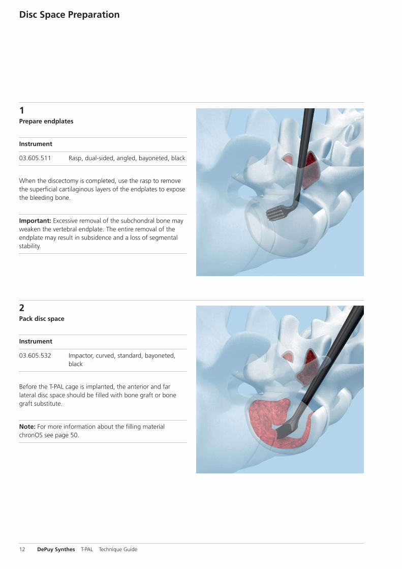
1Prepare endplates
Instrument
03.605.511 Rasp, dual-sided, angled, bayoneted, black
When the discectomy is completed, use the rasp to removethe superficial cartilaginous layers of the endplates to exposethe bleeding bone.
Important: Excessive removal of the subchondral bone mayweaken the vertebral endplate. The entire removal of theendplate may result in subsidence and a loss of segmentalstability.
Disc Space Preparation
2Pack disc space
Instrument
03.605.532 Impactor, curved, standard, bayoneted, black
Before the T-PAL cage is implanted, the anterior and far lateral disc space should be filled with bone graft or bonegraft substitute.
Note: For more information about the filling materialchronOS see page 50.
12 DePuy Synthes T-PAL Technique Guide
1
2
3
Trial for Implant Size
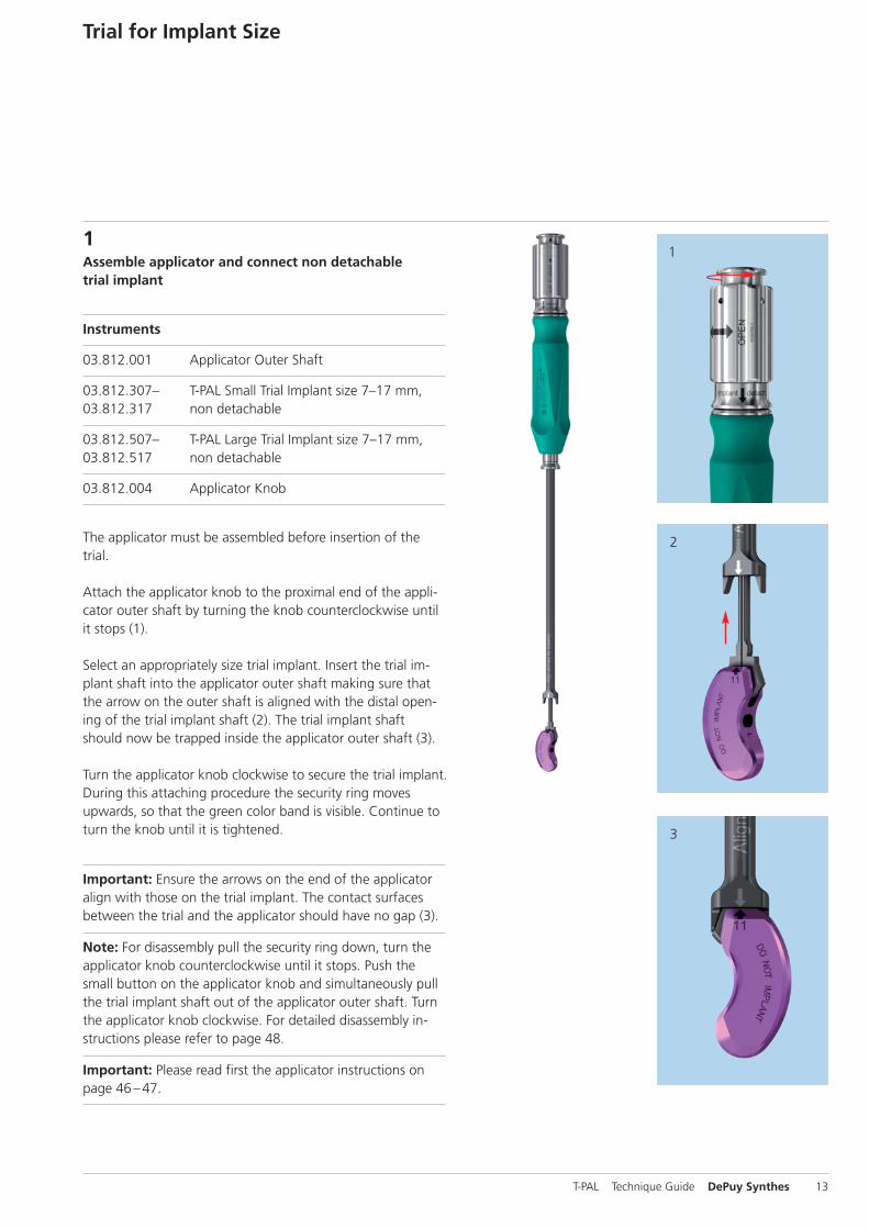
1Assemble applicator and connect non detachable trial implant
Instruments
03.812.001 Applicator Outer Shaft
03.812.307– T-PAL Small Trial Implant size 7–17 mm, 03.812.317 non detachable
03.812.507– T-PAL Large Trial Implant size 7–17 mm, 03.812.517 non detachable
03.812.004 Applicator Knob
The applicator must be assembled before insertion of thetrial.
Attach the applicator knob to the proximal end of the appli-cator outer shaft by turning the knob counterclockwise untilit stops (1).
Select an appropriately size trial implant. Insert the trial im-plant shaft into the applicator outer shaft making sure thatthe arrow on the outer shaft is aligned with the distal open-ing of the trial implant shaft (2). The trial implant shaftshould now be trapped inside the applicator outer shaft (3).
Turn the applicator knob clockwise to secure the trial implant.During this attaching procedure the security ring moves upwards, so that the green color band is visible. Continue toturn the knob until it is tightened.
Important: Ensure the arrows on the end of the applicatoralign with those on the trial implant. The contact surfacesbetween the trial and the applicator should have no gap (3).
Note: For disassembly pull the security ring down, turn theapplicator knob counterclockwise until it stops. Push thesmall button on the applicator knob and simultaneously pullthe trial implant shaft out of the applicator outer shaft. Turnthe applicator knob clockwise. For detailed disassembly in-structions please refer to page 48.
Important: Please read first the applicator instructions onpage 46 –47.
T-PAL Technique Guide DePuy Synthes 13
1
2
3
Trial for Implant Size
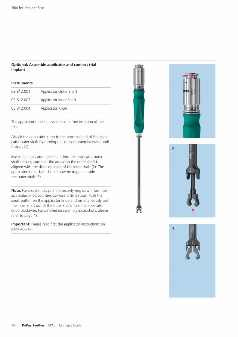
Optional: Assemble applicator and connect trialimplant
Instruments
03.812.001 Applicator Outer Shaft
03.812.003 Applicator Inner Shaft
03.812.004 Applicator Knob
The applicator must be assembled before insertion of thetrial.
Attach the applicator knob to the proximal end of the appli-cator outer shaft by turning the knob counterclockwise untilit stops (1).
Insert the applicator inner shaft into the applicator outershaft making sure that the arrow on the outer shaft isaligned with the distal opening of the inner shaft (2). The applicator inner shaft should now be trapped insidethe outer shaft (3).
Note: For disassembly pull the security ring down, turn theapplicator knob counterclockwise until it stops. Push thesmall button on the applicator knob and simultaneously pullthe inner shaft out of the outer shaft. Turn the applicatorknob clockwise. For detailed disassembly instructions pleaserefer to page 48.
Important: Please read first the applicator instructions onpage 46 –47.
14 DePuy Synthes T-PAL Technique Guide
1 2
3
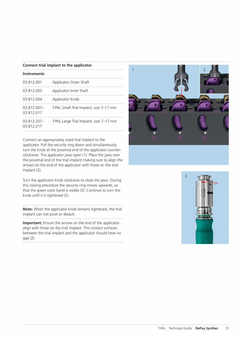
Connect trial implant to the applicator
Instruments
03.812.001 Applicator Outer Shaft
03.812.003 Applicator Inner Shaft
03.812.004 Applicator Knob
03.812.007– T-PAL Small Trial Implant, size 7–17 mm03.812.017
03.812.207– T-PAL Large Trial Implant, size 7–17 mm03.812.217
Connect an appropriately sized trial implant to theapplicator. Pull the security ring down and simultaneouslyturn the knob at the proximal end of the applicator counter-clockwise. The applicator jaws open (1). Place the jaws overthe proximal end of the trial implant making sure to align thearrows on the end of the applicator with those on the trialimplant (2).
Turn the applicator knob clockwise to close the jaws. Duringthis closing procedure the security ring moves upwards, sothat the green color band is visible (3). Continue to turn theknob until it is tightened (2).
Note: When the applicator knob remains tightened, the trialimplant can not pivot or detach.
Important: Ensure the arrows on the end of the applicatoralign with those on the trial implant. The contact surfacesbetween the trial implant and the applicator should have nogap (2).
T-PAL Technique Guide DePuy Synthes 15
10 –15°
1
2
3
Trial for Implant Size
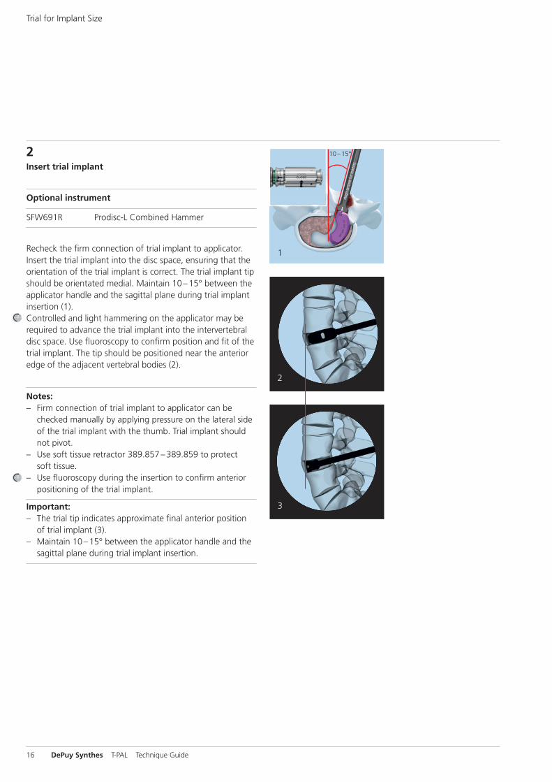
2Insert trial implant
Optional instrument
SFW691R Prodisc-L Combined Hammer
Recheck the firm connection of trial implant to applicator. Insert the trial implant into the disc space, ensuring that theorientation of the trial implant is correct. The trial implant tipshould be orientated medial. Maintain 10 –15° between theapplicator handle and the sagittal plane during trial implantinsertion (1).Controlled and light hammering on the applicator may be required to advance the trial implant into the intervertebraldisc space. Use fluoroscopy to confirm position and fit of thetrial implant. The tip should be positioned near the anterioredge of the adjacent vertebral bodies (2).
Notes:– Firm connection of trial implant to applicator can be
checked manually by applying pressure on the lateral sideof the trial implant with the thumb. Trial implant shouldnot pivot.
– Use soft tissue retractor 389.857 –389.859 to protectsoft tissue.
– Use fluoroscopy during the insertion to confirm anteriorpositioning of the trial implant.
Important:– The trial tip indicates approximate final anterior position
of trial implant (3).– Maintain 10 –15° between the applicator handle and the
sagittal plane during trial implant insertion.
16 DePuy Synthes T-PAL Technique Guide
10 –15°
10 –15°
2
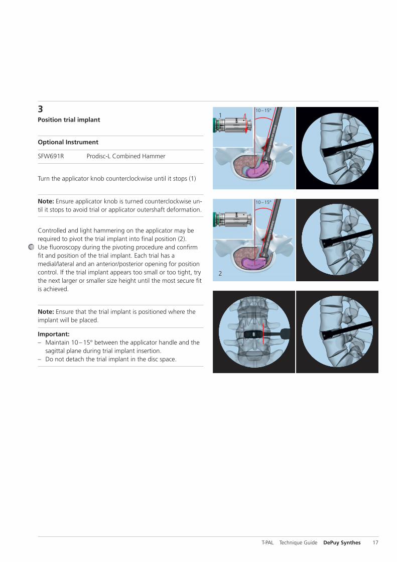
13 Position trial implant
Optional Instrument
SFW691R Prodisc-L Combined Hammer
Turn the applicator knob counterclockwise until it stops (1)
Note: Ensure applicator knob is turned counterclockwise un-til it stops to avoid trial or applicator outershaft deformation.
Controlled and light hammering on the applicator may be required to pivot the trial implant into final position (2).Use fluoroscopy during the pivoting procedure and confirmfit and position of the trial implant. Each trial has amedial/lateral and an anterior/posterior opening for positioncontrol. If the trial implant appears too small or too tight, trythe next larger or smaller size height until the most secure fitis achieved.
Note: Ensure that the trial implant is positioned where theimplant will be placed.
Important:– Maintain 10 –15° between the applicator handle and the
sagittal plane during trial implant insertion.– Do not detach the trial implant in the disc space.
T-PAL Technique Guide DePuy Synthes 17

10 –15°
1 2
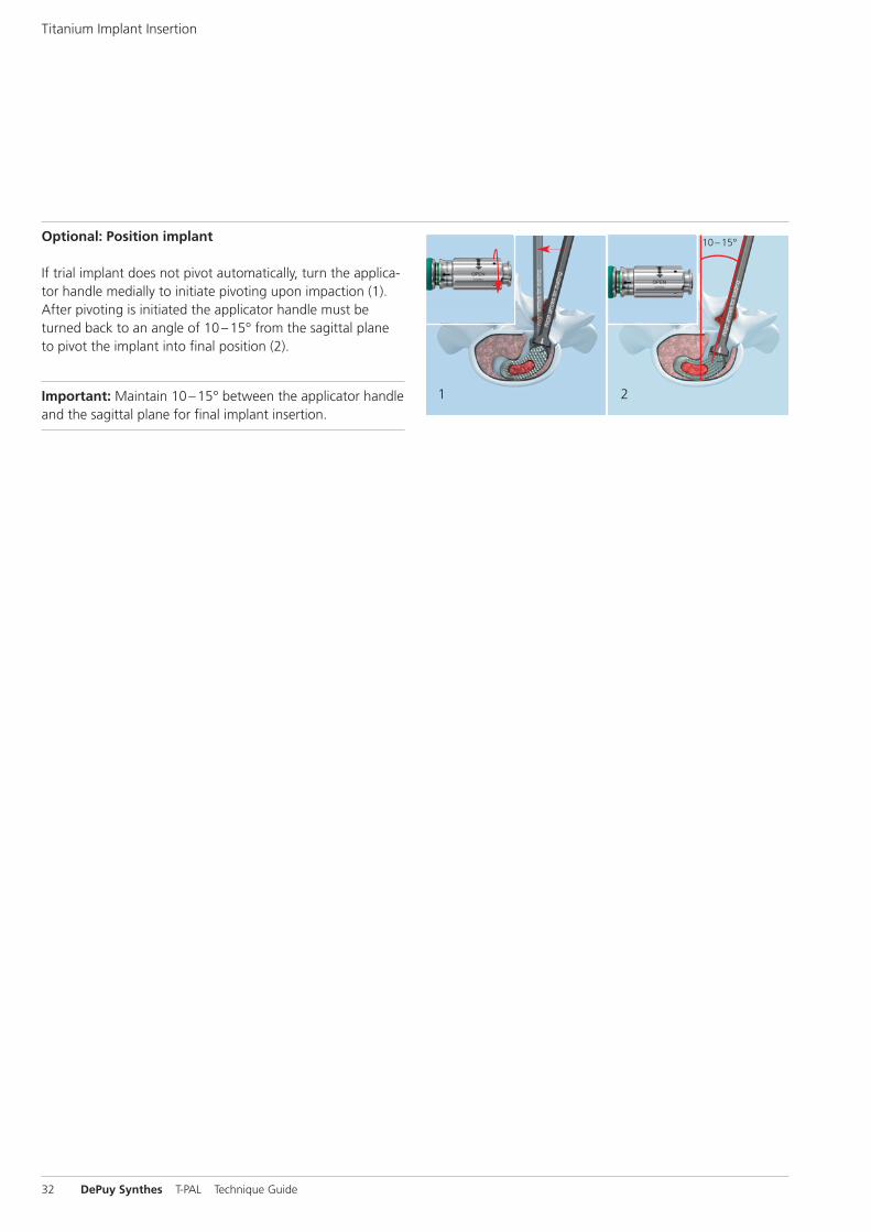
Optional: Position trial implant
If trial implant does not pivot automatically, turn the applica-tor handle medially to initiate pivoting upon impaction (1).After pivoting is initiated the applicator handle must beturned back to an angle of 10 –15° from the sagittal planeto pivot the trial implant into final position (2).
Important: Maintain 10 –15° between the applicator handleand the sagittal plane for final trial implant insertion.
Trial for Implant Size
18 DePuy Synthes T-PAL Technique Guide
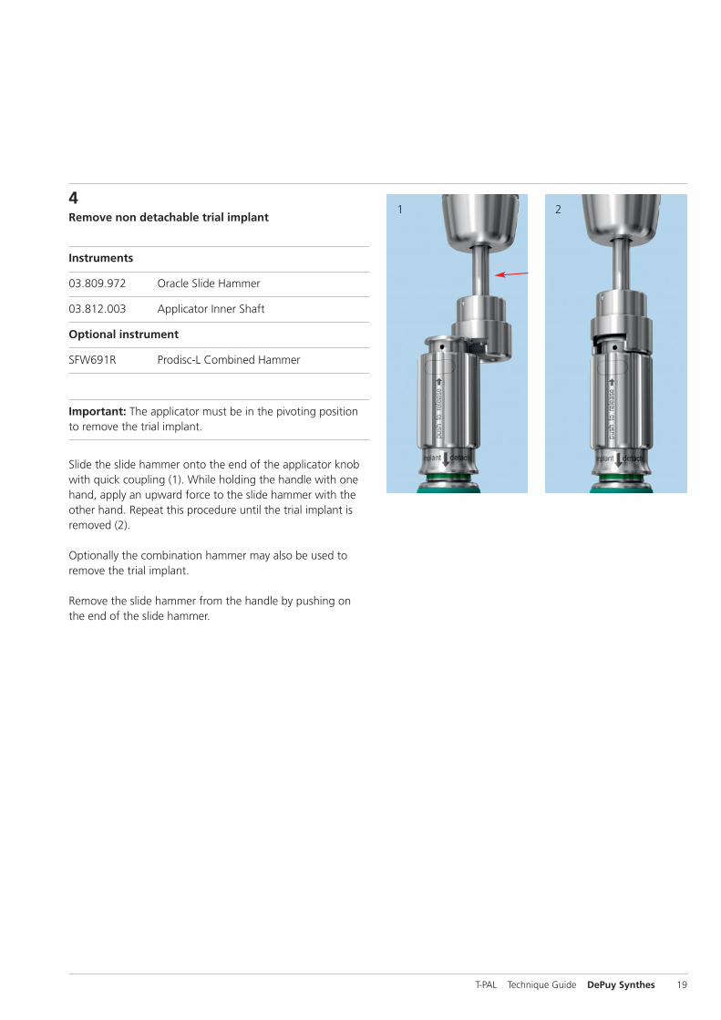
1 24Remove non detachable trial implant
Instruments
03.809.972 Oracle Slide Hammer
03.812.003 Applicator Inner Shaft
Optional instrument
SFW691R Prodisc-L Combined Hammer
Important: The applicator must be in the pivoting positionto remove the trial implant.
Slide the slide hammer onto the end of the applicator knobwith quick coupling (1). While holding the handle with onehand, apply an upward force to the slide hammer with theother hand. Repeat this procedure until the trial implant is removed (2).
Optionally the combination hammer may also be used to remove the trial implant.
Remove the slide hammer from the handle by pushing onthe end of the slide hammer.
T-PAL Technique Guide DePuy Synthes 19
43
5
Trial for Implant Size
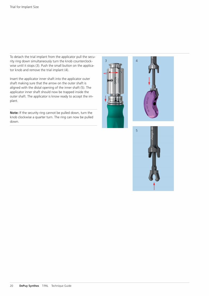
To detach the trial implant from the applicator pull the secu-rity ring down simultaneously turn the knob counterclock-wise until it stops (3). Push the small button on the applica-tor knob and remove the trial implant (4).
Insert the applicator inner shaft into the applicator outershaft making sure that the arrow on the outer shaft isaligned with the distal opening of the inner shaft (5). The applicator inner shaft should now be trapped inside theouter shaft. The applicator is know ready to accept the im-plant.
Note: If the security ring cannot be pulled down, turn theknob clockwise a quarter turn. The ring can now be pulleddown.
20 DePuy Synthes T-PAL Technique Guide
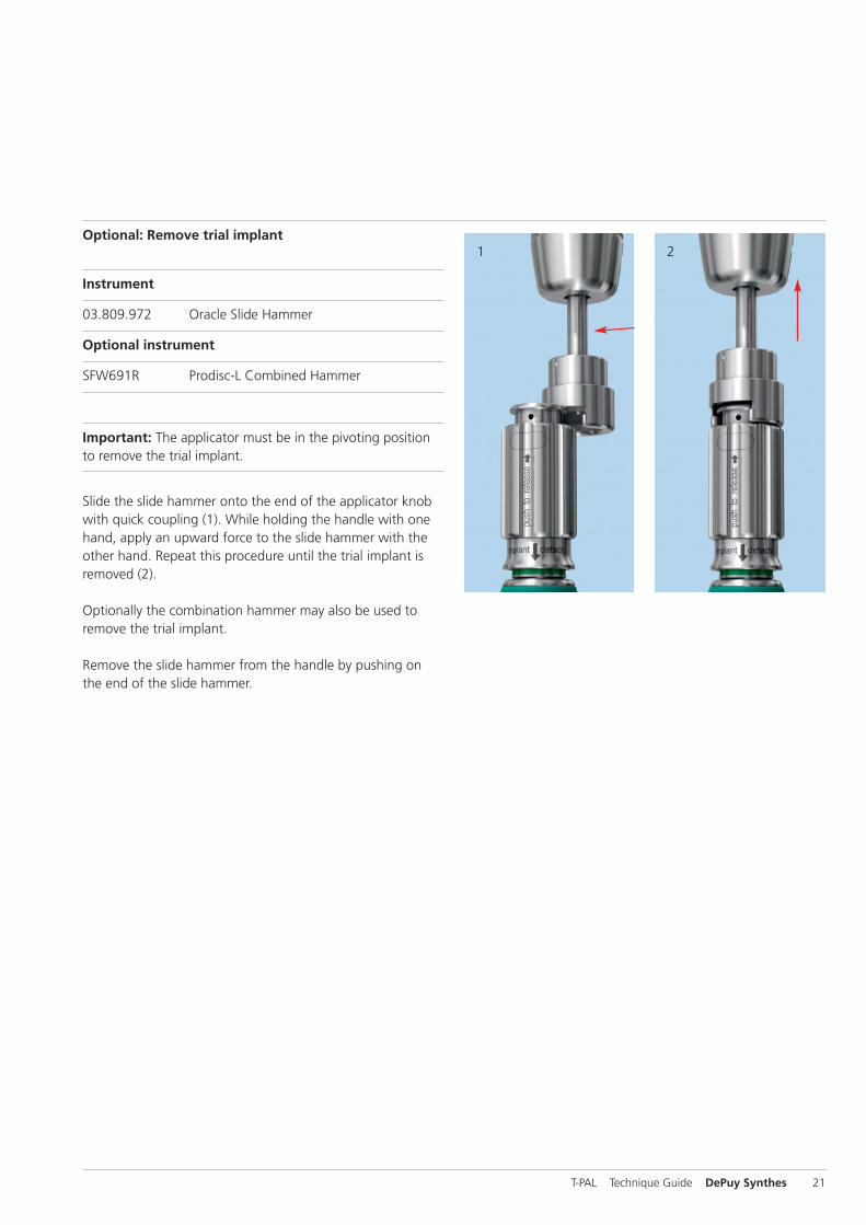
1 2Optional: Remove trial implant
Instrument
03.809.972 Oracle Slide Hammer
Optional instrument
SFW691R Prodisc-L Combined Hammer
Important: The applicator must be in the pivoting positionto remove the trial implant.
Slide the slide hammer onto the end of the applicator knobwith quick coupling (1). While holding the handle with onehand, apply an upward force to the slide hammer with theother hand. Repeat this procedure until the trial implant is removed (2).
Optionally the combination hammer may also be used to remove the trial implant.
Remove the slide hammer from the handle by pushing onthe end of the slide hammer.
T-PAL Technique Guide DePuy Synthes 21
43
Trial for Implant Size
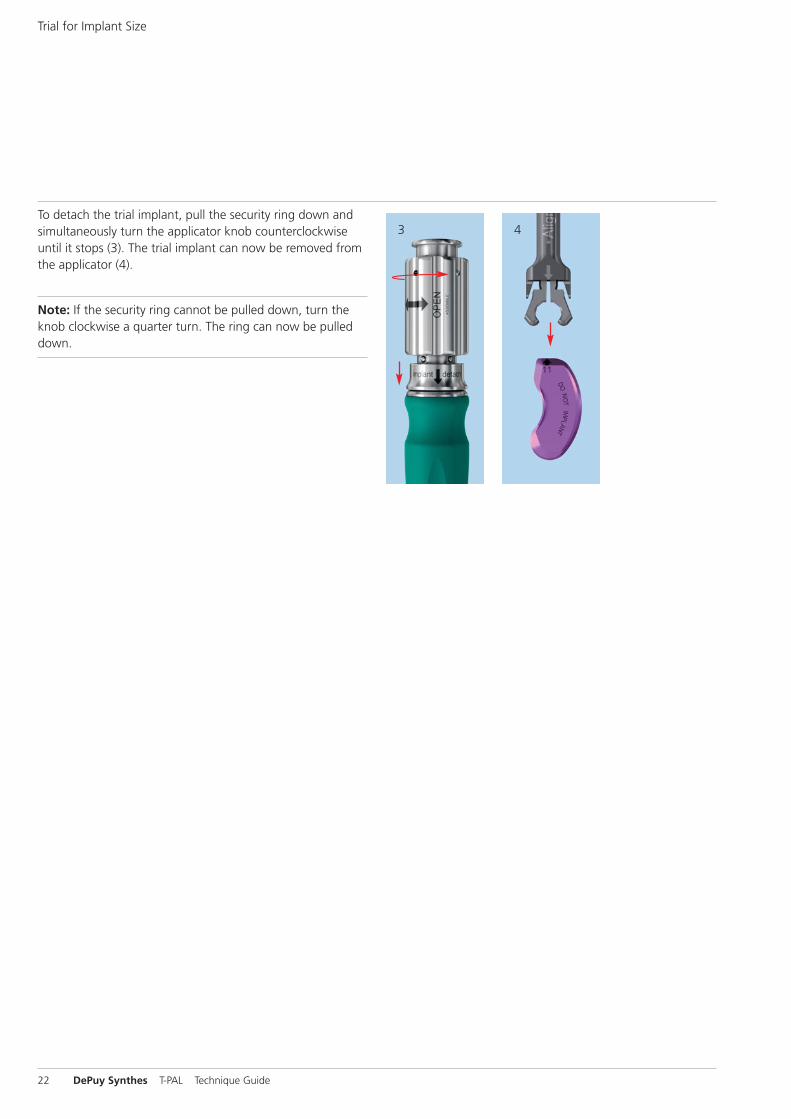
To detach the trial implant, pull the security ring down andsimultaneously turn the applicator knob counterclockwiseuntil it stops (3). The trial implant can now be removed fromthe applicator (4).
Note: If the security ring cannot be pulled down, turn theknob clockwise a quarter turn. The ring can now be pulleddown.
22 DePuy Synthes T-PAL Technique Guide
Implant Preparation
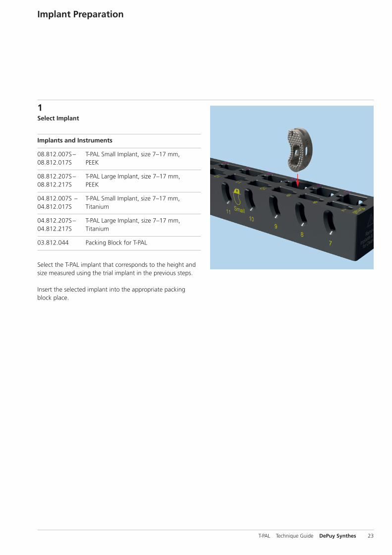
1Select Implant
Implants and Instruments
08.812.007S– T-PAL Small Implant, size 7–17 mm, 08.812.017S PEEK
08.812.207S– T-PAL Large Implant, size 7–17 mm, 08.812.217S PEEK
04.812.007S – T-PAL Small Implant, size 7–17 mm, 04.812.017S Titanium
04.812.207S– T-PAL Large Implant, size 7–17 mm, 04.812.217S Titanium
03.812.044 Packing Block for T-PAL
Select the T-PAL implant that corresponds to the height andsize measured using the trial implant in the previous steps.
Insert the selected implant into the appropriate packingblock place.
T-PAL Technique Guide DePuy Synthes 23

1
2
3
2Pack implant with bone graft
Instrument
03.812.043 Cancellous Bone Impactor for T-PAL
Turn the packing block on its side and use the cancellousbone impactor to firmly pack the filling material into the im-plant cavities (1).
Make sure the implant is well placed in the packing block toavoid implant damage while bone graft filling (2).
It is important to fill the implant until the filling material protrudes from its perforations in order to ensure optimalcontact with the vertebral endplates (3).
For more information about the filling volumes, see page 38in this technique guide.
Note: For more information about the filling materialchronOS see page 50.
Implant Preparation
24 DePuy Synthes T-PAL Technique Guide
1
3
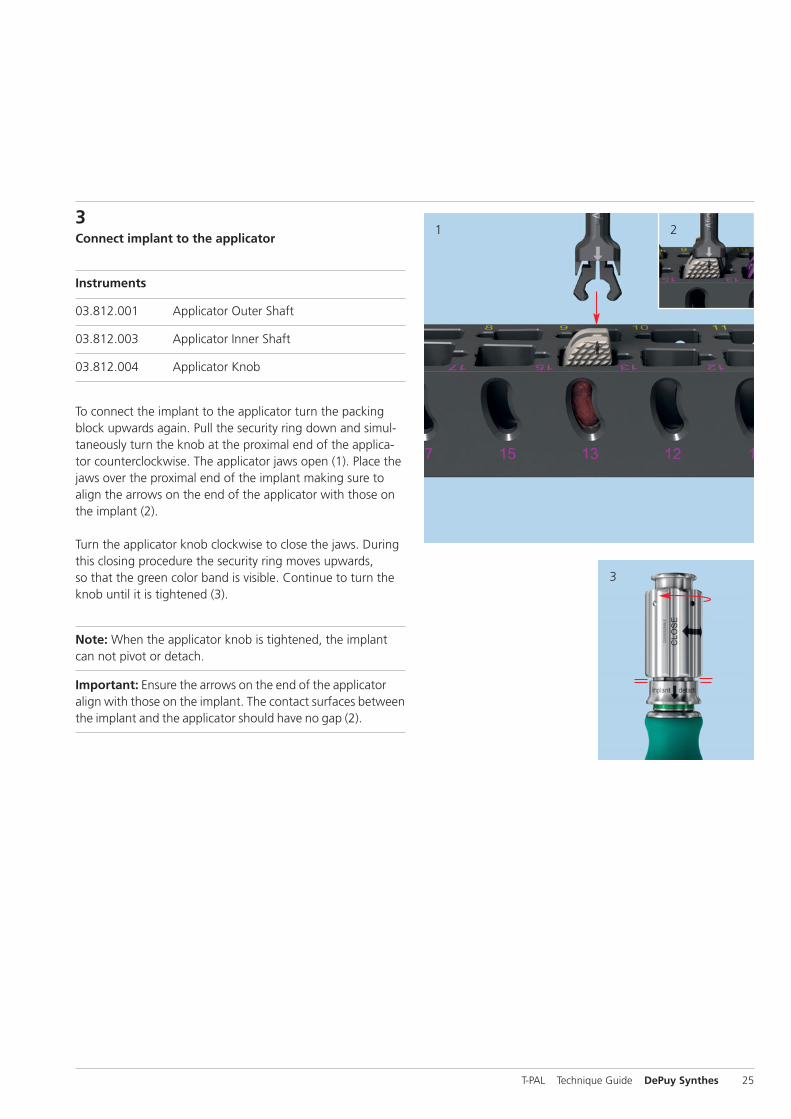
23Connect implant to the applicator
Instruments
03.812.001 Applicator Outer Shaft
03.812.003 Applicator Inner Shaft
03.812.004 Applicator Knob
To connect the implant to the applicator turn the packingblock upwards again. Pull the security ring down and simul-taneously turn the knob at the proximal end of the applica-tor counterclockwise. The applicator jaws open (1). Place thejaws over the proximal end of the implant making sure toalign the arrows on the end of the applicator with those onthe implant (2).
Turn the applicator knob clockwise to close the jaws. Duringthis closing procedure the security ring moves upwards,so that the green color band is visible. Continue to turn theknob until it is tightened (3).
Note: When the applicator knob is tightened, the implantcan not pivot or detach.
Important: Ensure the arrows on the end of the applicatoralign with those on the implant. The contact surfaces betweenthe implant and the applicator should have no gap (2).
T-PAL Technique Guide DePuy Synthes 25
10 –15°
1
2
3
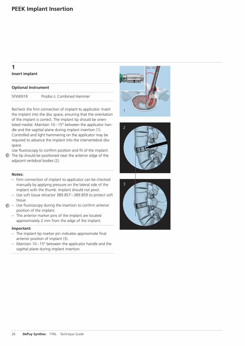
1Insert implant
Optional Instrument
SFW691R Prodisc-L Combined Hammer
Recheck the firm connection of implant to applicator. Insertthe implant into the disc space, ensuring that the orientationof the implant is correct. The implant tip should be orien-tated medial. Maintain 10 –15° between the applicator han-dle and the sagittal plane during implant insertion (1). Controlled and light hammering on the applicator may be required to advance the implant into the intervertebral discspace.Use fluoroscopy to confirm position and fit of the implant.The tip should be positioned near the anterior edge of theadjacent vertebral bodies (2).
Notes:– Firm connection of implant to applicator can be checked
manually by applying pressure on the lateral side of theimplant with the thumb. Implant should not pivot.
– Use soft tissue retractor 389.857 –389.859 to protect softtissue.
– Use fluoroscopy during the insertion to confirm anteriorposition of the implant.
– The anterior marker pins of the implant are located approximately 2 mm from the edge of the implant.
Important: – The implant tip marker pin indicates approximate final
anterior position of implant (3).– Maintain 10 –15° between the applicator handle and the
sagittal plane during implant insertion.
PEEK Implant Insertion
26 DePuy Synthes T-PAL Technique Guide
10 –15°
10 –15°1
2
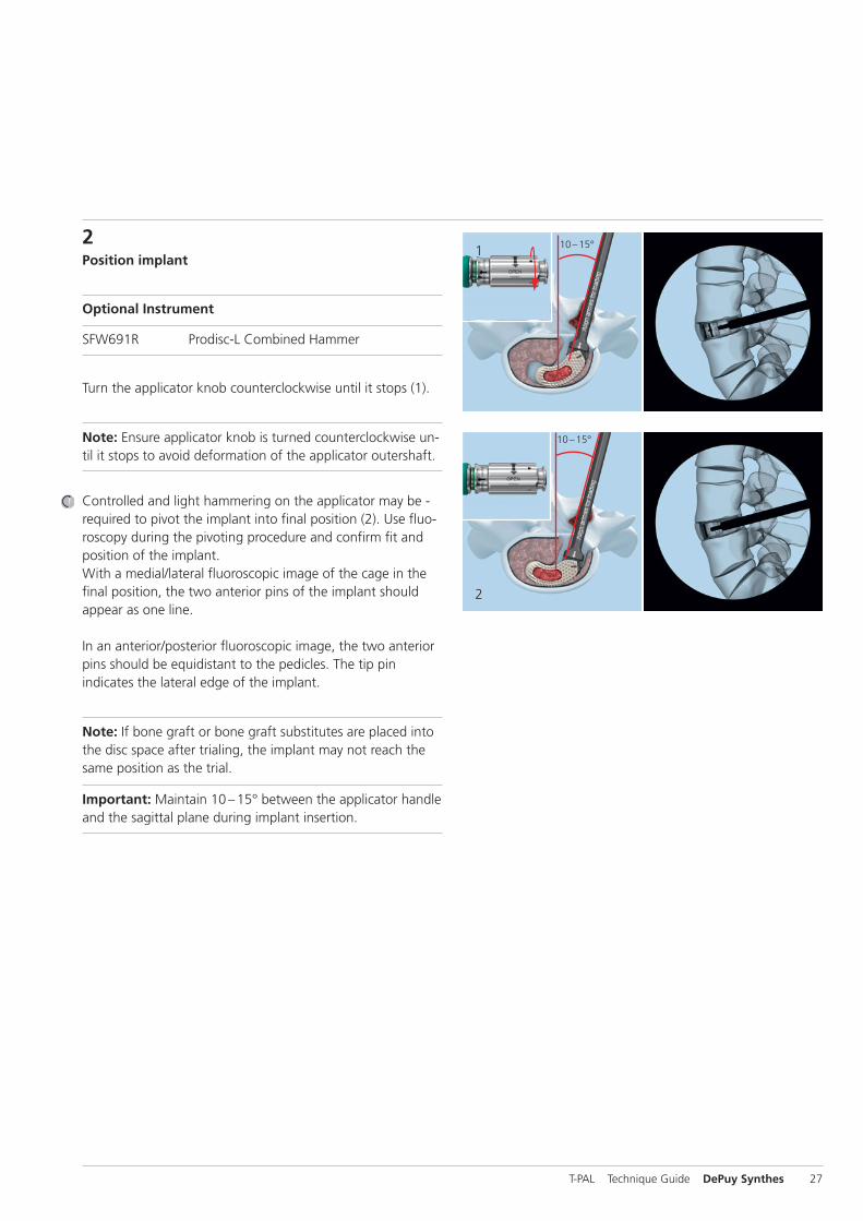
2 Position implant
Optional Instrument
SFW691R Prodisc-L Combined Hammer
Turn the applicator knob counterclockwise until it stops (1).
Note: Ensure applicator knob is turned counterclockwise un-til it stops to avoid deformation of the applicator outershaft.
Controlled and light hammering on the applicator may be -required to pivot the implant into final position (2). Use fluo-roscopy during the pivoting procedure and confirm fit andposition of the implant. With a medial/lateral fluoroscopic image of the cage in thefinal position, the two anterior pins of the implant should appear as one line.
In an anterior/posterior fluoroscopic image, the two anteriorpins should be equidistant to the pedicles. The tip pin indicates the lateral edge of the implant.
Note: If bone graft or bone graft substitutes are placed intothe disc space after trialing, the implant may not reach thesame position as the trial.
Important: Maintain 10 –15° between the applicator handleand the sagittal plane during implant insertion.
T-PAL Technique Guide DePuy Synthes 27
10 –15°
1 2
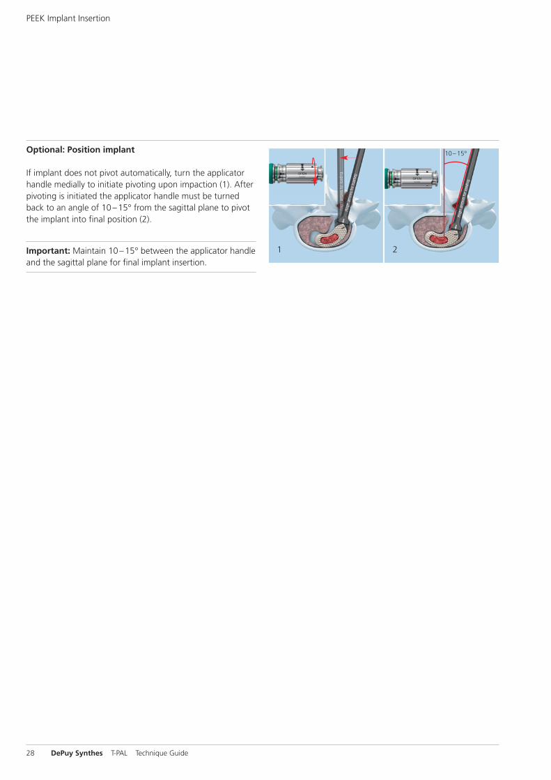
Optional: Position implant
If implant does not pivot automatically, turn the applicatorhandle medially to initiate pivoting upon impaction (1). Afterpivoting is initiated the applicator handle must be turnedback to an angle of 10 –15° from the sagittal plane to pivotthe implant into final position (2).
Important: Maintain 10 –15° between the applicator handleand the sagittal plane for final implant insertion.
PEEK Implant Insertion
28 DePuy Synthes T-PAL Technique Guide

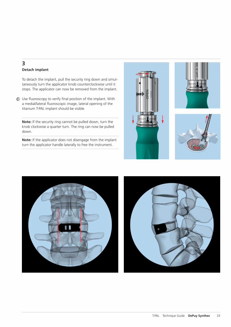
3Detach implant
To detach the implant, pull the security ring down and simul-taneously turn the applicator knob counterclockwise until itstops. The applicator can now be removed from the implant.
Use fluoroscopy to verify final position of the implant. Witha medial/lateral fluoroscopic image, the two anterior pinsof the implant should appear as one line and the tip markeras a dot.
Note: If the security ring cannot be pulled down, turn theknob clockwise a quarter turn. The ring can now be pulleddown.
Note: If the applicator does not disengage from the implantturn the applicator handle laterally to free the instrument.
T-PAL Technique Guide DePuy Synthes 29
10 –15°
2
3
Titanium Implant Insertion
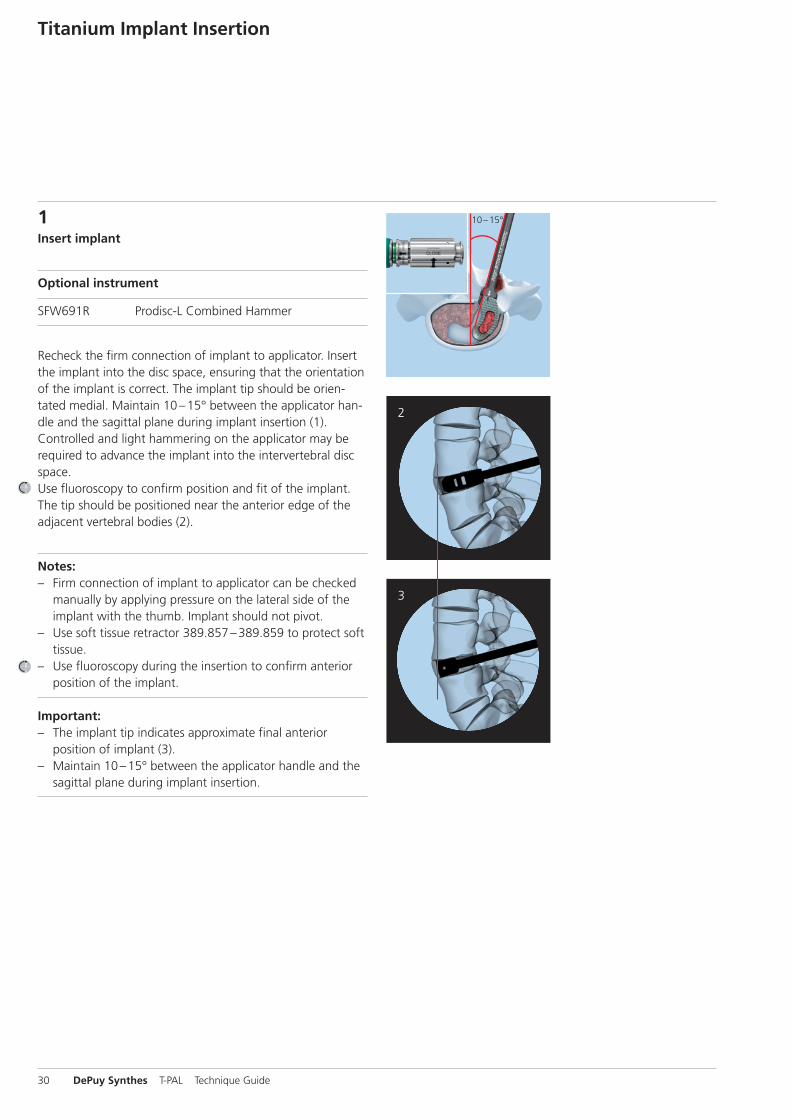
1Insert implant
Optional instrument
SFW691R Prodisc-L Combined Hammer
Recheck the firm connection of implant to applicator. Insertthe implant into the disc space, ensuring that the orientationof the implant is correct. The implant tip should be orien-tated medial. Maintain 10 –15° between the applicator han-dle and the sagittal plane during implant insertion (1). Controlled and light hammering on the applicator may be required to advance the implant into the intervertebral discspace.Use fluoroscopy to confirm position and fit of the implant.The tip should be positioned near the anterior edge of theadjacent vertebral bodies (2).
Notes:– Firm connection of implant to applicator can be checked
manually by applying pressure on the lateral side of theimplant with the thumb. Implant should not pivot.
– Use soft tissue retractor 389.857 –389.859 to protect softtissue.
– Use fluoroscopy during the insertion to confirm anteriorposition of the implant.
Important: – The implant tip indicates approximate final anterior
position of implant (3).– Maintain 10 –15° between the applicator handle and the
sagittal plane during implant insertion.
30 DePuy Synthes T-PAL Technique Guide

10 –15°
10 –15°
1
2
2 Position implant
Optional instrument
SFW691R Prodisc-L Combined Hammer
Turn the applicator knob counterclockwise until it stops (1).
Note: Ensure applicator knob is turned counterclockwise un-til it stops to avoid deformation of the applicator outershaft.
Controlled and light hammering on the applicator may be required to pivot the implant into final position (2). Use fluoroscopy during the pivoting procedure and confirmfit and position of the implant. Each implant has a medial/lat-eral and an anterior/posterior opening for position control.
Note: If bone graft or bone graft substitutes are placed intothe disc space after trialing, the implant may not reach thesame position as the trial.
Important: Maintain 10 –15° between the applicator handleand the sagittal plane during implant insertion.
T-PAL Technique Guide DePuy Synthes 31
10 –15°
1 2
Optional: Position implant
If trial implant does not pivot automatically, turn the applica-tor handle medially to initiate pivoting upon impaction (1).After pivoting is initiated the applicator handle must beturned back to an angle of 10 –15° from the sagittal planeto pivot the implant into final position (2).
Important: Maintain 10 –15° between the applicator handleand the sagittal plane for final implant insertion.
Titanium Implant Insertion
32 DePuy Synthes T-PAL Technique Guide
3Detach implant
To detach the implant, pull the security ring down and simul-taneously turn the applicator knob counterclockwise until itstops. The applicator can now be removed from the implant.
Use fluoroscopy to verify final position of the implant. With a medial/lateral fluoroscopic image, lateral opening of the titanium T-PAL implant should be visible.
Note: If the security ring cannot be pulled down, turn theknob clockwise a quarter turn. The ring can now be pulleddown.
Note: If the applicator does not disengage from the implantturn the applicator handle laterally to free the instrument.
T-PAL Technique Guide DePuy Synthes 33

1Pack disc space
Instrument
03.605.532 Impactor, curved, standard, bayoneted, black
After the T-PAL cage is implanted, fill the posterior discspace and the lateral disc space with bone graft or bonegraft substitute to create optimal conditions for fusion.
Note: For more information about the filling materialchronOS see page 50.
Posterior Support
2Supplemental fixation
Sets (optional)
01.620.015 Pangea Polyaxial Basic Instruments in Vario Case
01.620.018 Pangea Polyaxial Implants in Vario Case
01.631.001 SpiRIT Set in Vario Case
01.631.005 SpiRIT Additional Instruments in Vario Case
01.631.004 MIS-Rods, radius 200 mm, in Vario Case
The T-PAL cage is intended to be used with Synthes supple-mental posterior fixation, e.g. SpiRIT with Pangea or Click’X.
34 DePuy Synthes T-PAL Technique Guide
Implant Removal
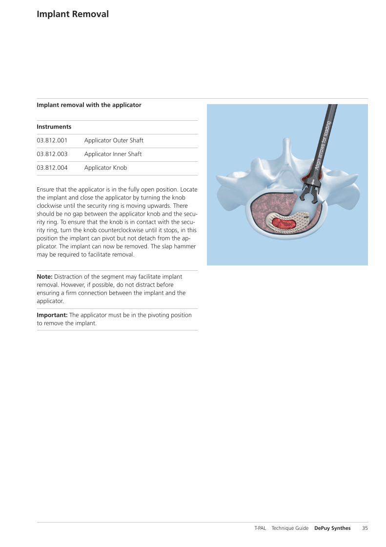
Implant removal with the applicator
Instruments
03.812.001 Applicator Outer Shaft
03.812.003 Applicator Inner Shaft
03.812.004 Applicator Knob
Ensure that the applicator is in the fully open position. Locatethe implant and close the applicator by turning the knobclockwise until the security ring is moving upwards. Thereshould be no gap between the applicator knob and the secu-rity ring. To ensure that the knob is in contact with the secu-rity ring, turn the knob counterclockwise until it stops, in thisposition the implant can pivot but not detach from the ap -plicator. The implant can now be removed. The slap hammermay be required to facilitate removal.
Note: Distraction of the segment may facilitate implant removal. However, if possible, do not distract before ensuring a firm connection between the implant and the applicator.
Important: The applicator must be in the pivoting positionto remove the implant.
T-PAL Technique Guide DePuy Synthes 35

Implant removal with the removal tool
Instrument
03.812.005 Removal Tool for T-PAL
Ensure that the removal tool for T-PAL is in the fully open po-sition. Locate the implant and squeeze the handle firmly. Advance the speed nut to lock the handle. The implant cannow be removed. The slap hammer may be required to facili-tate removal.
Note: When the removal tool handle is squeezed, the implant can pivot but not detach from the removal tool.
Note: Distraction of the segment may facilitate implant removal. However, if possible, do not distract before ensuring a firm connection between the implant and the removal tool.
Implant Removal
36 DePuy Synthes T-PAL Technique Guide

T-PAL Technique Guide DePuy Synthes 37
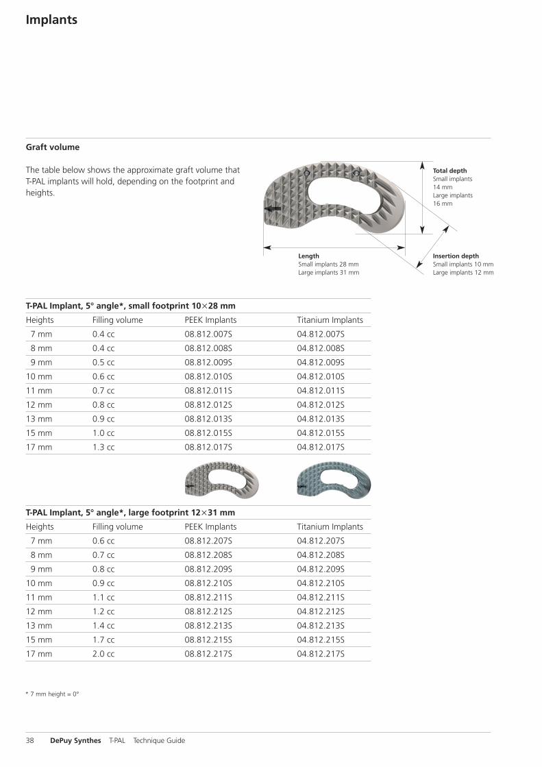
Graft volume
The table below shows the approximate graft volume that T-PAL implants will hold, depending on the footprint andheights.
Implants
Total depthSmall implants14 mmLarge implants16 mm
Insertion depthSmall implants 10 mmLarge implants 12 mm
LengthSmall implants 28 mmLarge implants 31 mm
* 7 mm height = 0°
T-PAL Implant, 5° angle*, small footprint 10u28 mm
Heights Filling volume PEEK Implants Titanium Implants
7 mm 0.4 cc 08.812.007S 04.812.007S
8 mm 0.4 cc 08.812.008S 04.812.008S
9 mm 0.5 cc 08.812.009S 04.812.009S
10 mm 0.6 cc 08.812.010S 04.812.010S
11 mm 0.7 cc 08.812.011S 04.812.011S
12 mm 0.8 cc 08.812.012S 04.812.012S
13 mm 0.9 cc 08.812.013S 04.812.013S
15 mm 1.0 cc 08.812.015S 04.812.015S
17 mm 1.3 cc 08.812.017S 04.812.017S
T-PAL Implant, 5° angle*, large footprint 12u31 mm
Heights Filling volume PEEK Implants Titanium Implants
7 mm 0.6 cc 08.812.207S 04.812.207S
8 mm 0.7 cc 08.812.208S 04.812.208S
9 mm 0.8 cc 08.812.209S 04.812.209S
10 mm 0.9 cc 08.812.210S 04.812.210S
11 mm 1.1 cc 08.812.211S 04.812.211S
12 mm 1.2 cc 08.812.212S 04.812.212S
13 mm 1.4 cc 08.812.213S 04.812.213S
15 mm 1.7 cc 08.812.215S 04.812.215S
17 mm 2.0 cc 08.812.217S 04.812.217S
38 DePuy Synthes T-PAL Technique Guide
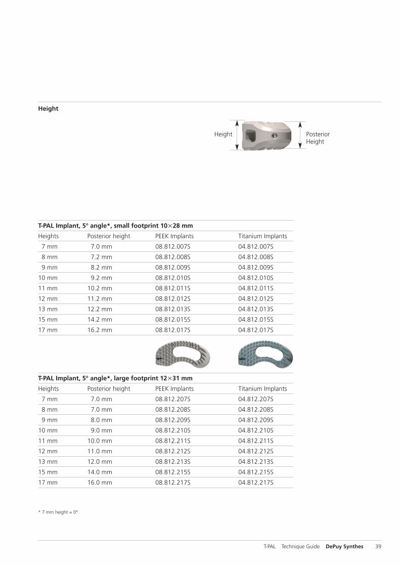
Height
Height Posterior Height
* 7 mm height = 0°
T-PAL Implant, 5° angle*, small footprint 10u28 mm
Heights Posterior height PEEK Implants Titanium Implants
7 mm 7.0 mm 08.812.007S 04.812.007S
8 mm 7.2 mm 08.812.008S 04.812.008S
9 mm 8.2 mm 08.812.009S 04.812.009S
10 mm 9.2 mm 08.812.010S 04.812.010S
11 mm 10.2 mm 08.812.011S 04.812.011S
12 mm 11.2 mm 08.812.012S 04.812.012S
13 mm 12.2 mm 08.812.013S 04.812.013S
15 mm 14.2 mm 08.812.015S 04.812.015S
17 mm 16.2 mm 08.812.017S 04.812.017S
T-PAL Implant, 5° angle*, large footprint 12u31 mm
Heights Posterior height PEEK Implants Titanium Implants
7 mm 7.0 mm 08.812.207S 04.812.207S
8 mm 7.0 mm 08.812.208S 04.812.208S
9 mm 8.0 mm 08.812.209S 04.812.209S
10 mm 9.0 mm 08.812.210S 04.812.210S
11 mm 10.0 mm 08.812.211S 04.812.211S
12 mm 11.0 mm 08.812.212S 04.812.212S
13 mm 12.0 mm 08.812.213S 04.812.213S
15 mm 14.0 mm 08.812.215S 04.812.215S
17 mm 16.0 mm 08.812.217S 04.812.217S
T-PAL Technique Guide DePuy Synthes 39
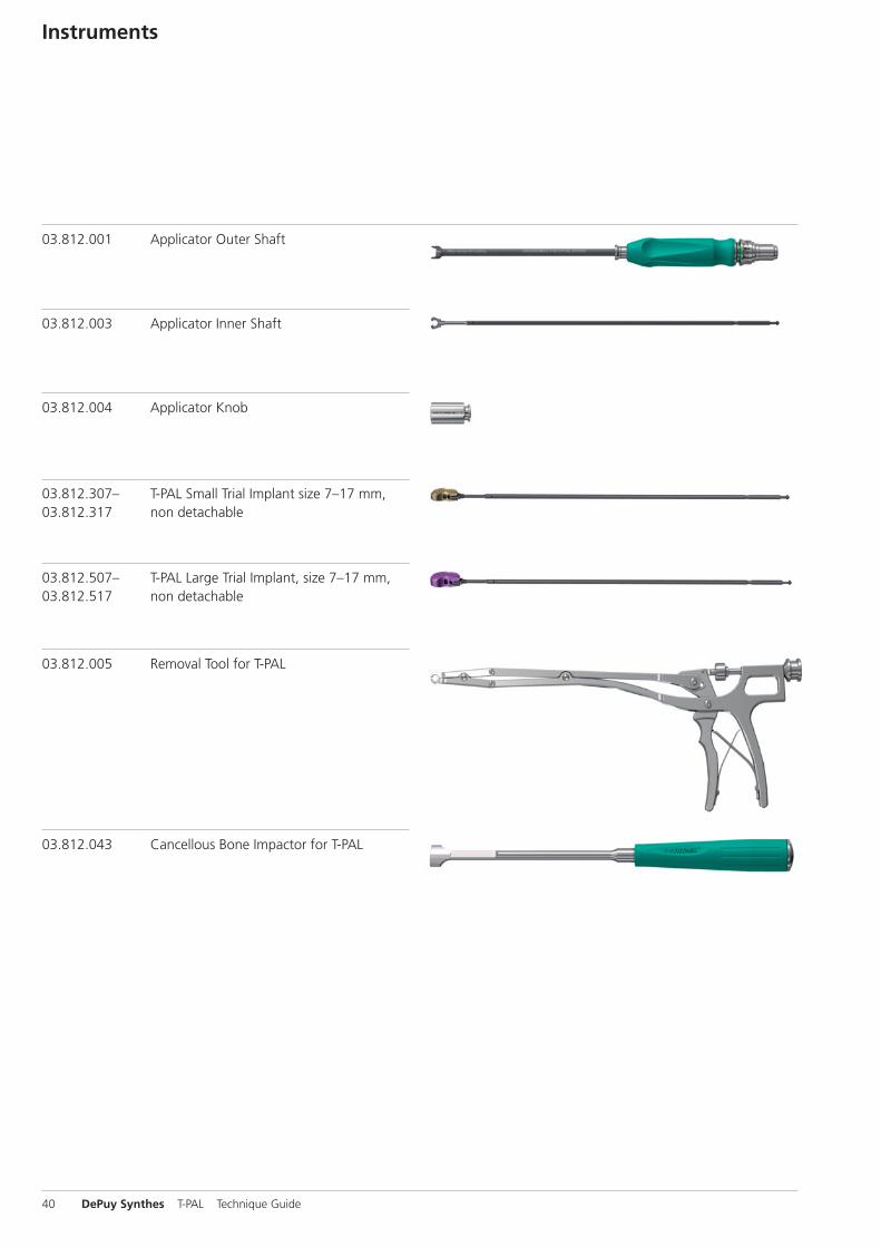
03.812.001 Applicator Outer Shaft
03.812.003 Applicator Inner Shaft
03.812.004 Applicator Knob
03.812.005 Removal Tool for T-PAL
03.812.043 Cancellous Bone Impactor for T-PAL
Instruments
03.812.307– T-PAL Small Trial Implant size 7–17 mm, 03.812.317 non detachable
03.812.507– T-PAL Large Trial Implant, size 7–17 mm, 03.812.517 non detachable
40 DePuy Synthes T-PAL Technique Guide
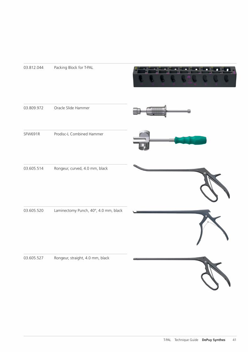
03.809.972 Oracle Slide Hammer
SFW691R Prodisc-L Combined Hammer
03.812.044 Packing Block for T-PAL
03.605.514 Rongeur, curved, 4.0 mm, black
03.605.520 Laminectomy Punch, 40°, 4.0 mm, black
03.605.527 Rongeur, straight, 4.0 mm, black
T-PAL Technique Guide DePuy Synthes 41
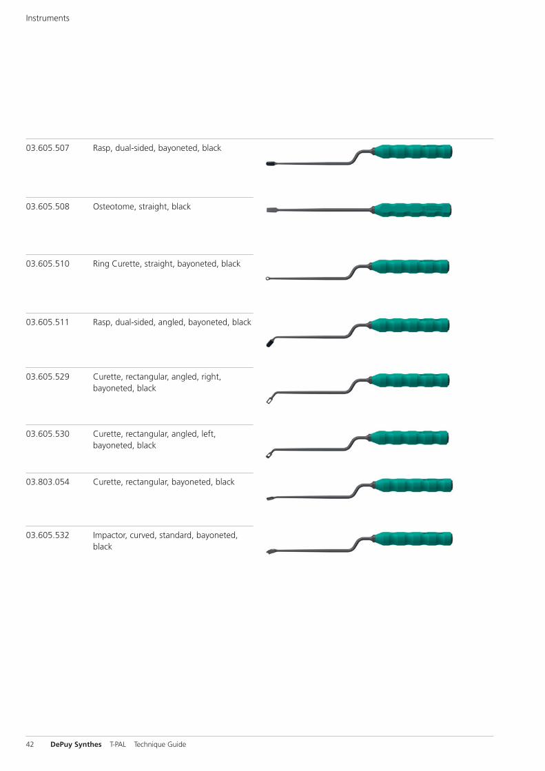
Instruments
03.605.529 Curette, rectangular, angled, right,bayoneted, black
03.605.530 Curette, rectangular, angled, left,bayoneted, black
03.803.054 Curette, rectangular, bayoneted, black
03.605.532 Impactor, curved, standard, bayoneted,black
03.605.508 Osteotome, straight, black
03.605.507 Rasp, dual-sided, bayoneted, black
03.605.510 Ring Curette, straight, bayoneted, black
03.605.511 Rasp, dual-sided, angled, bayoneted, black
42 DePuy Synthes T-PAL Technique Guide
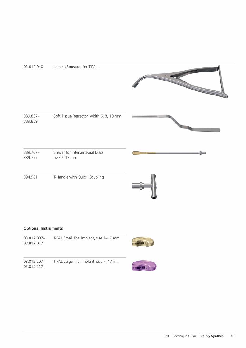
389.857 – Soft Tissue Retractor, width 6, 8, 10 mm389.859
389.767– Shaver for Intervertebral Discs, 389.777 size 7–17 mm
394.951 T-Handle with Quick Coupling
03.812.040 Lamina Spreader for T-PAL
03.812.007– T-PAL Small Trial Implant, size 7–17 mm03.812.017
03.812.207– T-PAL Large Trial Implant, size 7–17 mm03.812.217
Optional Instruments
T-PAL Technique Guide DePuy Synthes 43

Sets
Vario Case
68.812.001 Vario Case for T-PAL
Instruments
03.812.001 Applicator Outer Shaft
03.812.003 Applicator Inner Shaft
03.812.004 Applicator Knob
03.812.005 Removal Tool for T-PAL
03.812.307– T-PAL Small Trial Implant, size 7–17 mm, 03.812.317 non detachable
03.812.507– T-PAL Large Trial Implant, size 7–17 mm, 03.812.517 non detachable
03.812.043 Cancellous Bone Impactor for T-PAL
03.812.044 Packing Block for T-PAL
03.809.972 Oracle Slide Hammer
SFW691R Prodisc-L Combined Hammer
44 DePuy Synthes T-PAL Technique Guide
Vario Case
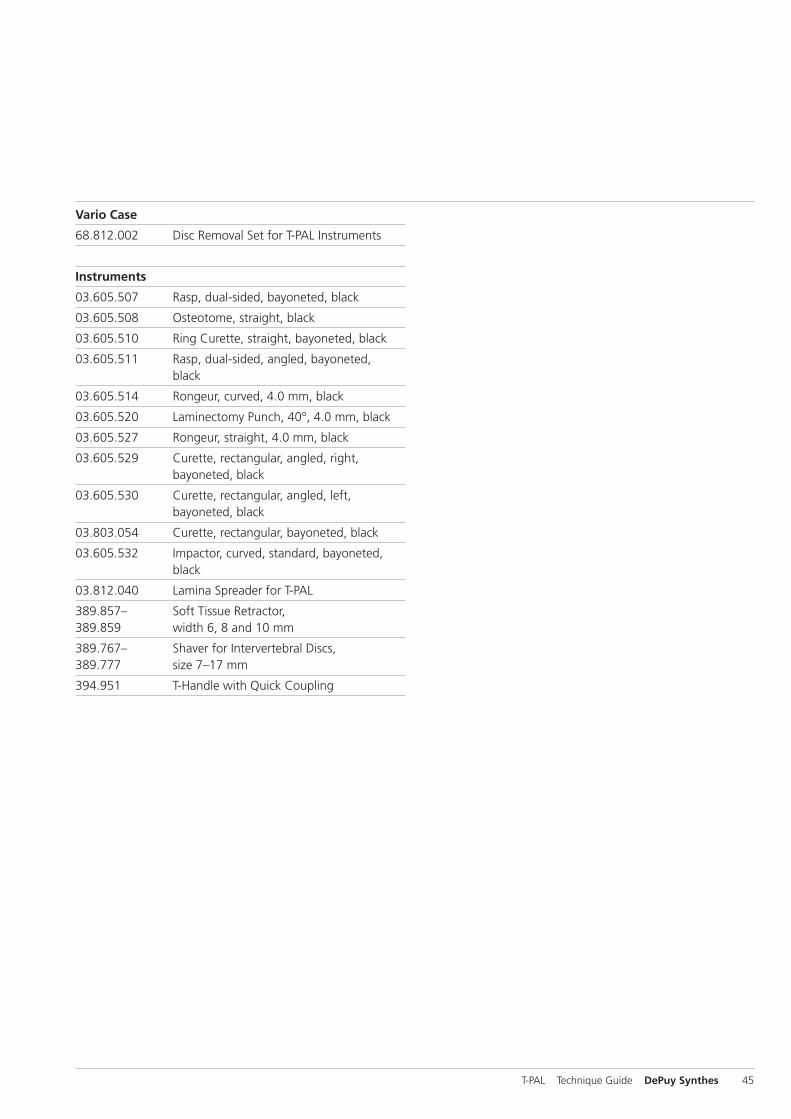
68.812.002 Disc Removal Set for T-PAL Instruments
Instruments
03.605.507 Rasp, dual-sided, bayoneted, black
03.605.508 Osteotome, straight, black
03.605.510 Ring Curette, straight, bayoneted, black
03.605.511 Rasp, dual-sided, angled, bayoneted, black
03.605.514 Rongeur, curved, 4.0 mm, black
03.605.520 Laminectomy Punch, 40°, 4.0 mm, black
03.605.527 Rongeur, straight, 4.0 mm, black
03.605.529 Curette, rectangular, angled, right, bayoneted, black
03.605.530 Curette, rectangular, angled, left, bayoneted, black
03.803.054 Curette, rectangular, bayoneted, black
03.605.532 Impactor, curved, standard, bayoneted, black
03.812.040 Lamina Spreader for T-PAL
389.857– Soft Tissue Retractor,389.859 width 6, 8 and 10 mm
389.767– Shaver for Intervertebral Discs, 389.777 size 7–17 mm
394.951 T-Handle with Quick Coupling
T-PAL Technique Guide DePuy Synthes 45
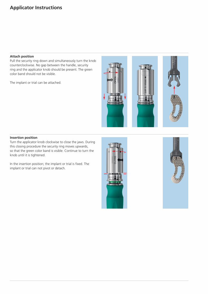
Attach positionPull the security ring down and simultaneously turn the knobcounterclockwise. No gap between the handle, security ring and the applicator knob should be present. The greencolor band should not be visible.
The implant or trial can be attached.
Insertion positionTurn the applicator knob clockwise to close the jaws. Duringthis closing procedure the security ring moves upwards,so that the green color band is visible. Continue to turn theknob until it is tightened.
In the insertion position; the implant or trial is fixed. The implant or trial can not pivot or detach.
Applicator Instructions
˙˙
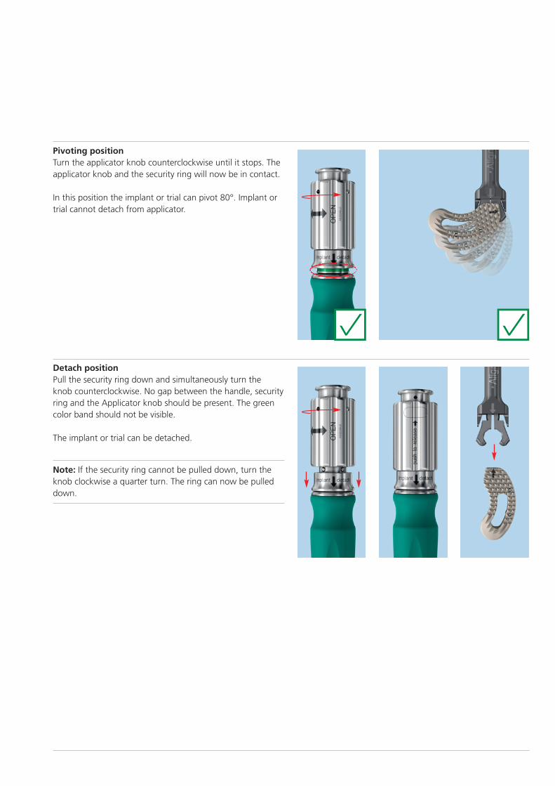
Pivoting positionTurn the applicator knob counterclockwise until it stops. Theapplicator knob and the security ring will now be in contact.
In this position the implant or trial can pivot 80°. Implant ortrial cannot detach from applicator.
Detach positionPull the security ring down and simultaneously turn theknob counterclockwise. No gap between the handle, securityring and the Applicator knob should be present. The greencolor band should not be visible.
The implant or trial can be detached.
Note: If the security ring cannot be pulled down, turn theknob clockwise a quarter turn. The ring can now be pulleddown.
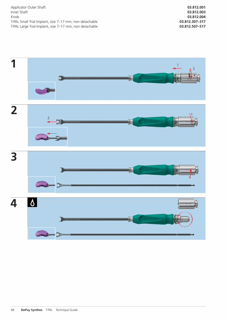
1
2
12
12
1
3
Applicator Outer ShaftInner ShaftKnobT-PAL Small Trial Implant, size 7–17 mm, non detachableT-PAL Large Trial Implant, size 7–17 mm, non detachable
03.812.00103.812.00303.812.004
03.812.307–31703.812.507–517
4
48 DePuy Synthes T-PAL Technique Guide
˙H
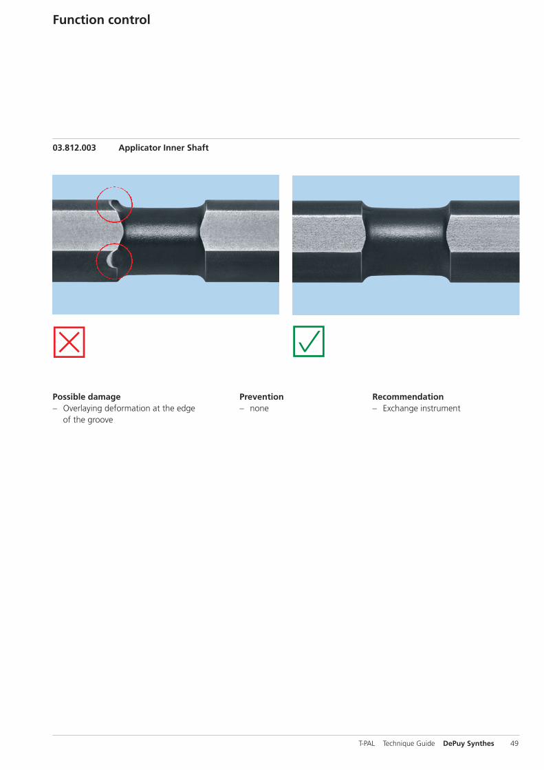
Possible damage– Overlaying deformation at the edge
of the groove
Prevention– none
Recommendation– Exchange instrument
Function control
03.812.003 Applicator Inner Shaft
T-PAL Technique Guide DePuy Synthes 49
Filling Material
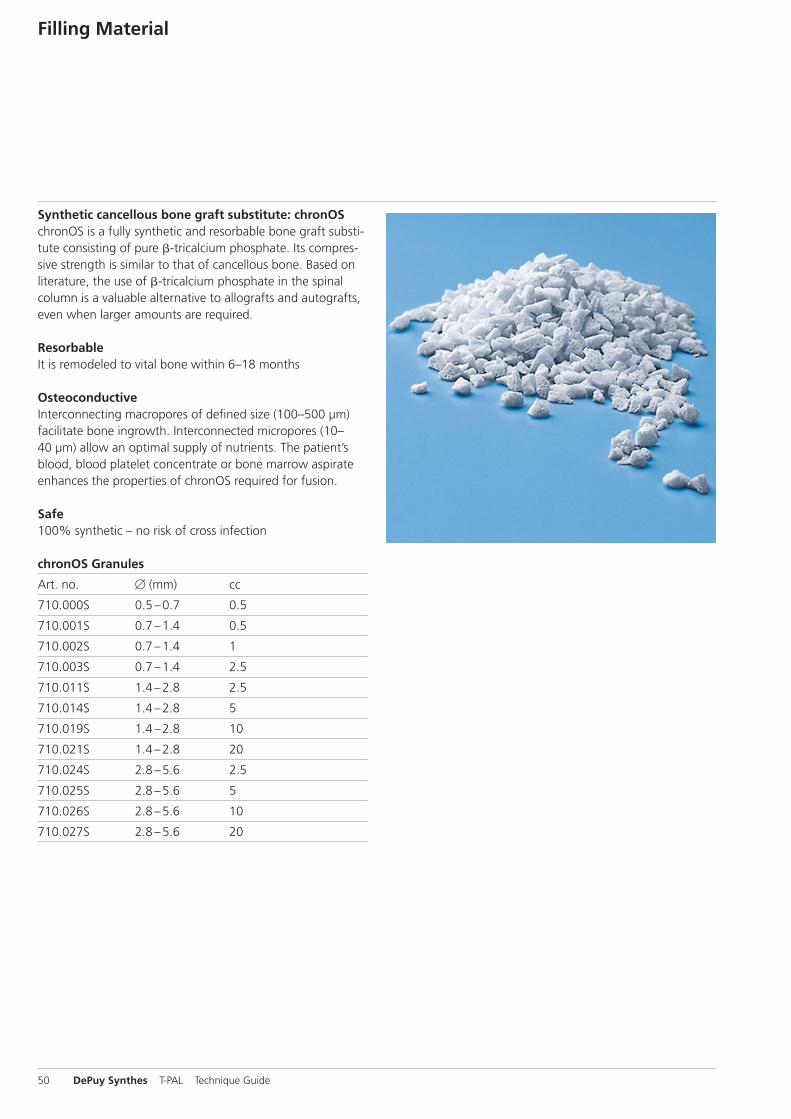
Synthetic cancellous bone graft substitute: chronOSchronOS is a fully synthetic and resorbable bone graft substi-tute consisting of pure �-tricalcium phosphate. Its compres-sive strength is similar to that of cancellous bone. Based onliterature, the use of �-tricalcium phosphate in the spinal column is a valuable alternative to allografts and autografts,even when larger amounts are required.
ResorbableIt is remodeled to vital bone within 6–18 months
OsteoconductiveInterconnecting macropores of defined size (100–500 µm)facilitate bone ingrowth. Interconnected micropores (10–40 µm) allow an optimal supply of nutrients. The patient’sblood, blood platelet concentrate or bone marrow aspirateenhances the properties of chronOS required for fusion.
Safe100% synthetic – no risk of cross infection
chronOS Granules
Art. no. B (mm) cc
710.000S 0.5 –0.7 0.5
710.001S 0.7 –1.4 0.5
710.002S 0.7 –1.4 1
710.003S 0.7 –1.4 2.5
710.011S 1.4 –2.8 2.5
710.014S 1.4 –2.8 5
710.019S 1.4 –2.8 10
710.021S 1.4 –2.8 20
710.024S 2.8 –5.6 2.5
710.025S 2.8 –5.6 5
710.026S 2.8 –5.6 10
710.027S 2.8 –5.6 20
50 DePuy Synthes T-PAL Technique Guide

T-PAL Technique Guide DePuy Synthes 51

52 DePuy Synthes T-PAL Technique Guide


0123
Synthes GmbHEimattstrasse 3CH-4436 Oberdorfwww.depuysynthes.com ©
Syn
thes
Gm
bH 2
014.
All
right
s re
serv
ed.
036.001.088
AD DSEM/SPN
/0714/0145
07/2014
Ö036.001.088öAD"ä
This publication is not intended for distribution in the USA.
All technique guides are available as PDF files at www.synthes.com/lit