Embed Size (px)
DESCRIPTION
for engineering and science
Citation preview

ApplicationMaintenance-friendly control valve for the petrochemical indus-try and process engineeringValve size NPS ½ to 8Pressure rating Class 150 to 900Temperatures –325 to 842 °F (–200 to 450 °C)
Type 3291 Globe Valve with:• Type 3271 Pneumatic Actuator (Type 3291-1 Control Valve)
or• Type 3277 Pneumatic Actuator (Type 3291-7 Control Valve)
for integrated positioner attachment
Valve body made of:• Cast steel• Cast stainless steel• High-temperature cast steel• Cold-resisting cast steel
Low-noise valve plug with:• Metal sealing• Soft sealing• High-performance metal sealing• Balanced for handling large differential pressures
Quick and easy maintenance• Clamped-in seat for quick maintenance
The modular design of the control valves allows them to beequipped with various accessories:Positioners, limit switches, solenoid valves and other accessoriesaccording to IEC 60534-6 and NAMUR recommendation. SeeInformation Sheet T 8350 EN for details.
VersionsStandard version (Fig. 1) · Globe valve for temperatures from15 to 430 °F (–10 to 220 °C) · NPS ½ to 8Type 3291-1 (Fig. 1) · Type 3291 Globe Valve andType 3271 Pneumatic Actuator (refer to T 8310-1/-2 EN)Type 3291-7 · Type 3291 Globe Valve and Type 3277 Pneu-matic Actuator for integral positioner attachment (refer toT 8310-1 EN)
Other versions– Welding ends or welding-neck ends acc. to ANSI B16.25– Flow divider · For noise reduction, see Table 3c– Perforated plug trim · Refer to T 8086 EN– Insulating section or bellows seal · See Technical data– Heating jacket · On request– Additional handwheel · See Data Sheet T 8310-1/-2 EN
– Type 3291-3 Hand-operated Valve · With Type 3273Hand-operated Actuator for valves with max. 30 mm ratedtravel. Refer to T 8312 EN
– Type 3291-2 Electric Control Valve · Details on request– NACE version (sour gas) · On request
Associated Information Sheets T 8000-x ENAssociated Data Sheets forPneumatic Actuators T 8310-1, T 8310-2 EN
Edition November 2012
Data Sheet T 8072-1 EN
Series 290
Pneumatic Control Valves Type 3291-1 and Type 3291-7Globe Valve Type 3291
ANSI version
Fig. 1 � Type 3291-1 Pneumatic Control Valvewith Type 3271 Pneumatic Actuator

Principle of operationThe process medium flows from under the plug (flow to open) inthe direction indicated by the arrow. The position of the valveplug determines the cross-sectional area between the seat andplug.The version with bellows seal (Fig. 4) features a test connectionto allow the stainless steel bellows to be monitored for leakage,e.g. when the valve is used to control explosive or toxic media.A pressure-balanced plug (Fig. 3) can be used when high pres-sures or differential pressures act on the valve plug.The control valve can be fitted with a flow divider (Fig. 4, refer toTable 3c for further details) to reduce noise levels.
Fail-safe positionsDepending on how the compression springs are arranged in theactuator (see Data Sheets T 8310-1 EN and T 8310-2 EN fordetails), the control valve has two different fail-safe positionswhich become effective upon supply air failure:Actuator stem extends (FA)The actuator springs close the valve when the supply air fails.Actuator stem retracts (FE)The actuator springs open the valve when the supply air fails.
Note: Figs. 2 to 4 show configuration examples.
2 T 8072-1 EN
Fig. 4 · Type 3291 Valve with flanges, flow dividerand bellows seal with test connection
Fig. 2 · Type 3291-1 Control Valve with flanges andType 3271 Pneumatic Actuator
Fig. 3 · Type 3291 Valve with welding ends andinsulating section

3 T 8072-1 EN
Table 1 · Technical data for Type 3291
Material Cast steelA 352 LCC
Cast steelA 216 WCC
Cast steelA 217 WC6
Cast stainless steel
A 351 CF3M A 351 CF8M
Valve size NPS ½ to 8
Pressure rating 1) Class 150 to 900
End connections Flanges All ANSI versions
Welding ends According to ANSI B16.25
Seat/plug sealing Metal sealing · Soft sealing · High-performance metal sealing
Characteristic Equal percentage · Linear · Quick opening
Rangeability 50 : 1
Temperature ranges in °F (°C) · Permissible operating pressures acc. to pressure-temperature diagrams (see Information Sheet T 8000-2 EN)
Body without insulating section 14 to 428 °F (–10 to 220 °C) · Up to 660 °F (350 °C)with high-temperature packing depending on material
Body with Insulatingsection
–51 to 649 °F(–46 to 343 °C)
–20 to 800 °F(–29 to 427 °C)
–20 to 842 °F(–29 to 450 °C)
–324 to 842 °F(–198 to 450 °C)
–324 to 842 °F(–198 to 450 °C)
Bellowsseal
–51 to 649 °F(–46 to 343 °C)
–20 to 800 °F(–29 to 427 °C)
–20 to 842 °F(–29 to 450 °C)
–324 to 842 °F(–198 to 450 °C)
–324 to 842 °F(–198 to 450 °C)
Valveplug 2) Standard
Metal sealing –324 to 842 °F (–198 to 450 °C)
Soft sealing –324 to 428 °F (–198 to 220 °C)
BalancedPTFE ring –40 to 428 °F (–40 to 220 °C) · Lower temperatures on request
Graphite ring –40 to 842 °F (–40 to 450 °C)
Leakage class according to ANSI/FCI 70-2-2006
Valveplug Standard
Metal sealing IV · High-performance metal sealing: V
Soft sealing 3) VI
Balanced, metal sealing Standard: IV (with PTFE or graphite ring) · High-performance metal sealing: V (only with PTFE ring)
1) Class 900 for NPS 3 and larger on request2) Only in combination with suitable body material3) On request
Table 2 � Materials (EN material number)
Standard versionBody and flanges 1)
Cast steelA 352 LCC
Cast steelA 216 WCC
Cast steelA 217 WC6
Cast stainless steel
A 351 CF3M A 351 CF8M
Seat and plug 2) Metal sealing 1.4006/1.4404 1.4006/1.4404 1.4006/1.4404 1.4404 1.4404
Seal with Soft sealing PTFE with 15 % glass fiber
Balanced PTFE with carbon � Graphite
Guide bushings 1.4112 1.4112 2.4610 2.4610
Packing V-ring packing PTFE with carbon, spring 1.4310 or high-temperature packing
Body gasket Graphite seal with metal core
Insulating section 3)A352 LCC/A350 LF2
A216 WCC/A182 F12 Cl. 2
A105
A217 WC6/A182 F12 Cl. 2
A351 CF3M/A182 F316L
A351 CF8M/A182 F316
Bellows seal
Intermediate piece 3)A352 LCC/A350 LF2
A216 WCC/A182 F12 Cl. 2/
A105
A217 WC6/A182 F12 Cl. 2
A351 CF3M/A182 F316L
A351 CF8M/A182 F316
Metal bellows 1.4571
Heating jacket 1.4404/A240 316L
1) Refer also to pressure-temperature diagrams (T 8000-2 EN)2) Seat and metal-seated plug also available stellited or plug made of solid Stellite3) Depending on valve bonnet material
4 T 8072-1 EN
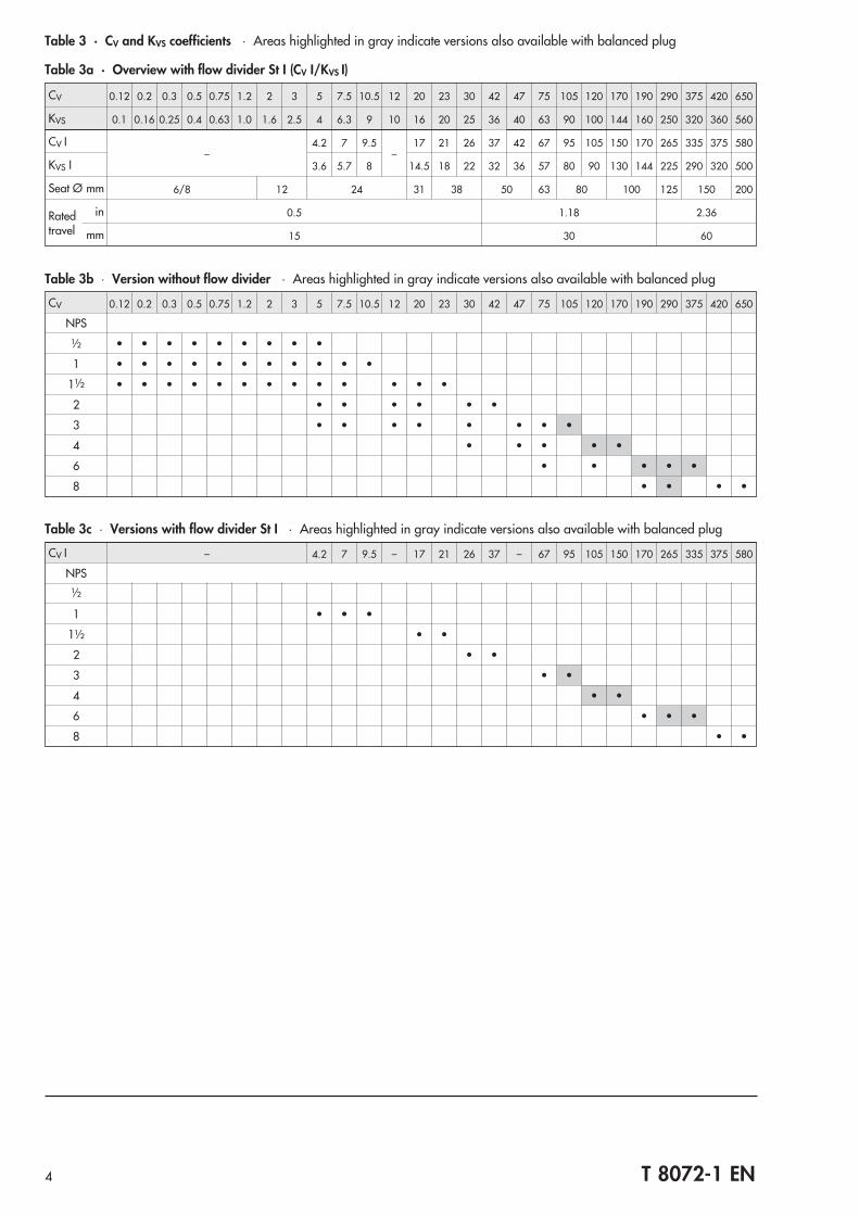
Table 3 · CV and KVS coefficients · Areas highlighted in gray indicate versions also available with balanced plug
Table 3a · Overview with flow divider St I (CV I/KVS I)
CV 0.12 0.2 0.3 0.5 0.75 1.2 2 3 5 7.5 10.5 12 20 23 30 42 47 75 105 120 170 190 290 375 420 650
KVS 0.1 0.16 0.25 0.4 0.63 1.0 1.6 2.5 4 6.3 9 10 16 20 25 36 40 63 90 100 144 160 250 320 360 560
CV I–
4.2 7 9.5–
17 21 26 37 42 67 95 105 150 170 265 335 375 580
KVS I 3.6 5.7 8 14.5 18 22 32 36 57 80 90 130 144 225 290 320 500
Seat Ø mm 6/8 12 24 31 38 50 63 80 100 125 150 200
Ratedtravel
in 0.5 1.18 2.36
mm 15 30 60
Table 3b � Version without flow divider · Areas highlighted in gray indicate versions also available with balanced plug
CV 0.12 0.2 0.3 0.5 0.75 1.2 2 3 5 7.5 10.5 12 20 23 30 42 47 75 105 120 170 190 290 375 420 650
NPS
½ • • • • • • • • •
1 • • • • • • • • • • •
1½ • • • • • • • • • • • • •
2 • • • • • •
3 • • • • • • • •
4 • • • • •
6 • • • • •
8 • • • •
Table 3c � Versions with flow divider St I · Areas highlighted in gray indicate versions also available with balanced plug
CV I – 4.2 7 9.5 – 17 21 26 37 – 67 95 105 150 170 265 335 375 580
NPS
½
1 • • •
1½ • •
2 • •
3 • •
4 • •
6 • • •
8 • •

5 T 8072-1 EN
Table 4 · Dimensions for Type 3291-1 and Type 3291-7 in standard version
Table 4.1 · Dimensions for Type 3291 Valve
Ventil NPS ½ 1 1½ 2 3 4 6 8
Length LClass 150
Flanges RF/welding ends(schedule 80)
in 7.24 7.24 8.74 10.0 11.73 13.86 17.76 21.38
mm 184 184 222 254 298 352 451 543
Flanges RTJin
–7.76 9.25 10.51 12.24 14.37 18.27 21.89
mm 197 235 267 311 365 464 556
Length LClass 300
Flanges RF/welding ends(schedule 80)
in 7.52 7.76 9.25 10.51 12.52 14.49 18.62 22.36
mm 191 197 235 267 318 368 473 568
Flanges RTJin 7.95 8.27 9.76 11.14 13.15 15.12 19.25 22.87
mm 202 210 248 283 334 384 489 581
Length LClass 600
Flanges RF/welding ends(schedule 80)
in 7.99 8.27 9.88 11.26 13.27 15.51 20 23.98
mm 203 210 251 286 337 394 508 609
Flanges RTJin 7.91 8.27 9.88 11.38 13.39 15.63 20.12 24.13
mm 201 210 251 289 340 397 511 613
Length LClass 900
Flanges RF/welding ends(schedule 80)
in 8.5 10 12.01 14.49 15 17.99 23.98 29.02
mm 216 254 305 368 381 457 609 737
Flanges RTJin 8.5 10 12.01 14.61 15.12 18.11 24.09 29.13
mm 216 254 305 371 384 460 612 740
H4
Class 150to 600
in 5.98 5.98 6.46 8.54 8.74 9.53 13.57 16.14
mm 152 152 164 217 222 242 337 410
Class 900in 7.32 7.32 7.68 9.88 8.74 9.53 13.27 16.14
mm 186 186 195 251 222 242 337 410
H8Yoke heightfor actuator
350 cm²in 9.45 9.45 9.45 9.45 9.45 9.45
–mm 240 240 240 240 240 240
355 cm²in 9.45 9.45 9.45 9.45 9.45 9.45 15.55
–mm 240 240 240 240 240 240 395
700 cm²in 9.45 9.45 9.45 9.45 9.45 9.45 15.55 15.55
mm 240 240 240 240 240 240 395 395
1000 cm²in
–11.61 11.61 11.61 15.55 15.55
mm 295 295 295 395 395
1400-60 cm²in
–11.61 11.61 11.61 15.55 15.55
mm 295 295 295 395 395
1400-120 cm²in
–18.90 18.90 18.90
mm 480 480 480
2800 cm²in
–18.90 18.90 18.90
mm 480 480 480
H2NPS 4and largerincludingbase
Class 150in 1.97 2.36 3.15 3.54 3.94 6.30 8.66 9.84
mm 50 60 80 90 100 160 220 250
Class 300to 600
in 2.34 2.76 3.54 3.94 4.72 7.09 9.25 10.63
mm 60 70 90 100 120 180 235 270
Class 900in 2.76 3.15 3.94 4.33 4.72 7.09 9.25 10.63
mm 70 80 100 110 120 180 235 270
6 T 8072-1 EN
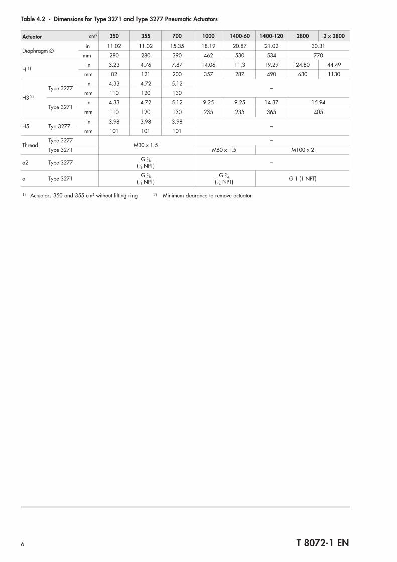
Table 4.2 · Dimensions for Type 3271 and Type 3277 Pneumatic Actuators
Actuator cm² 350 355 700 1000 1400-60 1400-120 2800 2 x 2800
Diaphragm Øin 11.02 11.02 15.35 18.19 20.87 21.02 30.31
mm 280 280 390 462 530 534 770
H 1)in 3.23 4.76 7.87 14.06 11.3 19.29 24.80 44.49
mm 82 121 200 357 287 490 630 1130
H3 2)
Type 3277in 4.33 4.72 5.12
–mm 110 120 130
Type 3271in 4.33 4.72 5.12 9.25 9.25 14.37 15.94
mm 110 120 130 235 235 365 405
H5 Typ 3277in 3.98 3.98 3.98
–mm 101 101 101
ThreadType 3277
M30 x 1.5–
Type 3271 M60 x 1.5 M100 x 2
a2 Type 3277 G 38
(38 NPT) –
a Type 3271 G 38
(38 NPT)
G 34
(34 NPT) G 1 (1 NPT)
1) Actuators 350 and 355 cm² without lifting ring 2) Minimum clearance to remove actuator
7 T 8072-1 EN
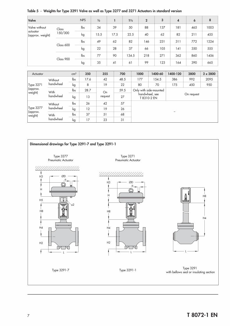
Dimensional drawings for Type 3291-7 and Type 3291-1
H4
H2
H5
H3
H
L
ØDa
a2
H8
Type 3277Pneumatic Actuator
Type 3291-7
ØDa
H
H2
L
H3
H4
H8
Type 3271Pneumatic Actuator
Type 3291-1
H4
H8
L
Type 3291with bellows seal or insulating section
Table 5 · Weights for Type 3291 Valve as well as Type 3277 and 3271 Actuators in standard version
Valve NPS ½ 1 1½ 2 3 4 6 8
Valve withoutactuator(approx. weight)
Class150/300
lbs 34 39 50 88 137 181 465 1003
kg 15.5 17.5 22.5 40 62 82 211 455
Class 600lbs 49 62 82 146 231 311 772 1224
kg 22 28 37 66 105 141 350 555
Class 900lbs 77 90 134.5 218 271 362 860 1456
kg 35 41 61 99 123 164 390 665
Actuator cm² 350 355 700 1000 1400-60 1400-120 2800 2 x 2800
Type 3271(approx.weight)
Withouthandwheel
lbs 17.6 42 48.5 177 154.5 386 992 2095
kg 8 19 22 80 70 175 450 950
Withhandwheel
lbs 28.7 Onrequest
59.5 Only with side-mountedhandwheel, seeT 8310-2 EN
On requestkg 13 27
Type 3277(approx.weight)
Withouthandwheel
lbs 26 42 57
–kg 12 19 26
Withhandwheel
lbs 37 51 68
kg 17 23 31
8 T 8072-1 EN
b
a a
d
a
b
c
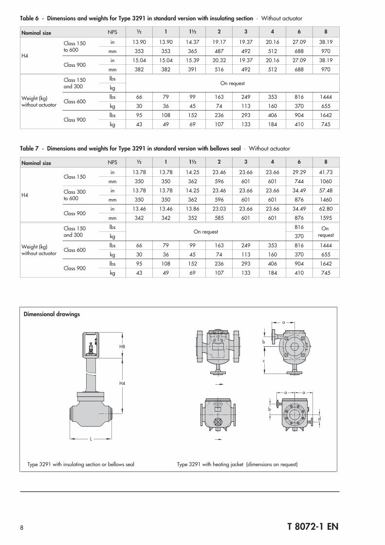
Type 3291 with insulating section or bellows seal Type 3291 with heating jacket (dimensions on request)
H4
H8
L
Dimensional drawings
Table 6 · Dimensions and weights for Type 3291 in standard version with insulating section · Without actuator
Nominal size NPS ½ 1 1½ 2 3 4 6 8
H4
Class 150to 600
in 13.90 13.90 14.37 19.17 19.37 20.16 27.09 38.19
mm 353 353 365 487 492 512 688 970
Class 900in 15.04 15.04 15.39 20.32 19.37 20.16 27.09 38.19
mm 382 382 391 516 492 512 688 970
Weight (kg)without actuator
Class 150and 300
lbsOn request
kg
Class 600lbs 66 79 99 163 249 353 816 1444
kg 30 36 45 74 113 160 370 655
Class 900lbs 95 108 152 236 293 406 904 1642
kg 43 49 69 107 133 184 410 745
Table 7 · Dimensions and weights for Type 3291 in standard version with bellows seal · Without actuator
Nominal size NPS ½ 1 1½ 2 3 4 6 8
H4
Class 150in 13.78 13.78 14.25 23.46 23.66 23.66 29.29 41.73
mm 350 350 362 596 601 601 744 1060
Class 300to 600
in 13.78 13.78 14.25 23.46 23.66 23.66 34.49 57.48
mm 350 350 362 596 601 601 876 1460
Class 900in 13.46 13.46 13.86 23.03 23.66 23.66 34.49 62.80
mm 342 342 352 585 601 601 876 1595
Weight (kg)without actuator
Class 150and 300
lbsOn request
816 Onrequestkg 370
Class 600lbs 66 79 99 163 249 353 816 1444
kg 30 36 45 74 113 160 370 655
Class 900lbs 95 108 152 236 293 406 904 1642
kg 43 49 69 107 133 184 410 745

Selection and sizing of control valves1. Calculate the CV (KV) coefficient according to IEC 60534.2. Select the valve size and CV (KVS) coefficient from Table 3.3. Determine the permissible differential pressure �p from the
Information Sheet T 8000-4 EN.4. Select the valve body material from Tables 1 and 2 as well
as from the pressure-temperature diagrams in theInformation Sheet T 8000-2 EN.
The following details are required on orderingValve size NPS …Pressure rating Class …Body material According to Table 2End connection Flanges/welding endsBonnet version Bonnet, insulating section or
bellows sealPlug Standard/balanced
Seal Soft sealing, metal sealing orhigh-performance metal sealing
Characteristic Equal percentage, linear or quickopening
Actuator Type 3271 or Type 3277(see T 8310-1 EN or T 8310-2 EN)
Fail-safe position Valve CLOSED or valve OPEN
Process medium Density and temperature(other medium data, if necessary)
Flow rate Under normal or operating conditionfor various cases
Pressure Upstream pressure p1 and downstreampressure p2 or differential pressure �pfor various cases
Accessories Positioner, limit switches, solenoid valveor others(refer to Information Sheet T 8350 ENfor details)
This document is exclusively intended to list the technical spec-ifications. The selection and sizing of the valves must beperformed by trained personnel.
Specifications subject to change without notice.
9 T 8072-1 EN

T 8072-1 EN
SAMSON AG · MESS- UND REGELTECHNIKWeismüllerstraße 3 · 60314 Frankfurt am Main · GermanyPhone: +49 69 4009-0 · Fax: +49 69 4009-1507Internet: http://www.samson.de 20
12-1
1


