Embed Size (px)
Citation preview
76 © 2018 Ernst & Sohn Verlag für Architektur und technische Wissenschaften GmbH & Co. KG, Berlin · Geomechanics and Tunnelling 11 (2018), No. 1
Topics
DOI: 10.1002/geot.201700063Dimitrios RizosDerek WilliamsAhmed Fouda
Tarek AminMohamed Abou DshieshAnis Dimitry Nicola
TBM tunnelling under the Suez Canal – Port Said tunnels in challenging ground conditions
The Port Said Tunnels Project consists of twin road tunnels crossing the Suez Canal with a planned capacity of 2,100 mixed vehicles/hour in each direction. The dual carriageway tunnels are an important part of the Suez Canal Region Development Plan, which will connect the Sinai with other Egyptian provinces to provide a gateway for investment opportunities and speed up the development of Sinai province. The project is located 19 km south of Port Said city, near the northern entrance of the Suez Canal. The tunnels are constructed using slurry shield TBMs in difficult ground conditions, including the presence of methane gas. This paper demonstrates the main challenges encountered during tunnelling and the measures taken to mitigate potential risks dur-ing construction and to control long-term differential settlements in the upper, very soft soil. The tunnels are connected by two cross passages which are being constructed using ground freez-ing and conventional tunnelling.
1 General
The Owner, the Engineering Authority of the Egyptian Armed Forces (EAAF), appointed Systra as their Consultant and the EPC Contract is being undertaken as a Joint Venture of two local Contractors, Arab Contractors and Orascom Construction. The project designer is Sener supported by Amberg. Wayss and Freytag were chosen to provide specialist support for the TBM tunnelling operation.
1.1 Project Description
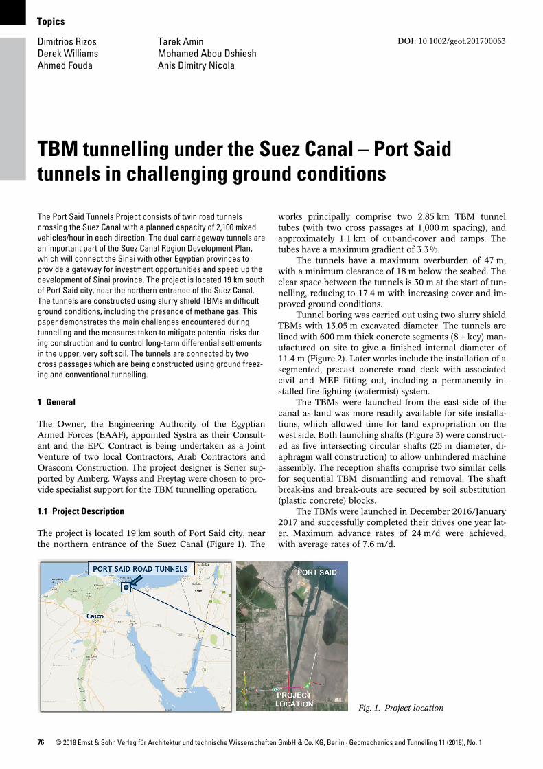
The project is located 19 km south of Port Said city, near the northern entrance of the Suez Canal (Figure 1). The
works principally comprise two 2.85 km TBM tunnel tubes (with two cross passages at 1,000 m spacing), and approximately 1.1 km of cutandcover and ramps. The tubes have a maximum gradient of 3.3 %.
The tunnels have a maximum overburden of 47 m, with a minimum clearance of 18 m below the seabed. The clear space between the tunnels is 30 m at the start of tunnelling, reducing to 17.4 m with increasing cover and improved ground conditions.
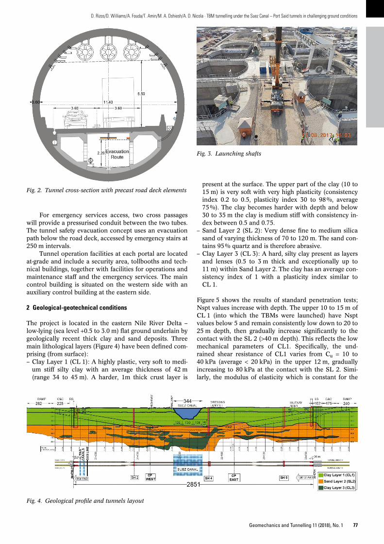
Tunnel boring was carried out using two slurry shield TBMs with 13.05 m excavated diameter. The tunnels are lined with 600 mm thick concrete segments (8 + key) manufactured on site to give a finished internal diameter of 11.4 m (Figure 2). Later works include the installation of a segmented, precast concrete road deck with associated civil and MEP fitting out, including a permanently installed fire fighting (watermist) system.
The TBMs were launched from the east side of the canal as land was more readily available for site installations, which allowed time for land expropriation on the west side. Both launching shafts (Figure 3) were constructed as five intersecting circular shafts (25 m diameter, diaphragm wall construction) to allow unhindered machine assembly. The reception shafts comprise two similar cells for sequential TBM dismantling and removal. The shaft breakins and breakouts are secured by soil substitution (plastic concrete) blocks.
The TBMs were launched in December 2016/January 2017 and successfully completed their drives one year later. Maximum advance rates of 24 m/d were achieved, with average rates of 7.6 m/d.
Fig. 1. Project location
77Geomechanics and Tunnelling 11 (2018), No. 1
D. Rizos/D. Williams/A. Fouda/T. Amin/M. A. Dshiesh/A. D. Nicola · TBM tunnelling under the Suez Canal – Port Said tunnels in challenging ground conditions
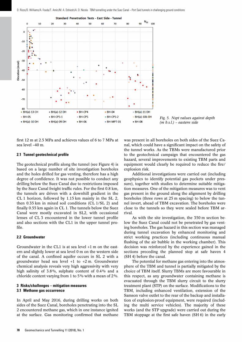
present at the surface. The upper part of the clay (10 to 15 m) is very soft with very high plasticity (consistency index 0.2 to 0.5, plasticity index 30 to 98 %, average 75 %). The clay becomes harder with depth and below 30 to 35 m the clay is medium stiff with consistency index between 0.5 and 0.75.
– Sand Layer 2 (SL 2): Very dense fine to medium silica sand of varying thickness of 70 to 120 m. The sand contains 95 % quartz and is therefore abrasive.
– Clay Layer 3 (CL 3): A hard, silty clay present as layers and lenses (0.5 to 3 m thick and exceptionally up to 11 m) within Sand Layer 2. The clay has an average consistency index of 1 with a plasticity index similar to CL 1.
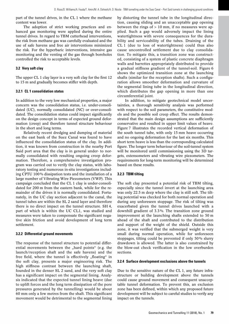
Figure 5 shows the results of standard penetration tests; Nspt values increase with depth. The upper 10 to 15 m of CL 1 (into which the TBMs were launched) have Nspt values below 5 and remain consistently low down to 20 to 25 m depth, then gradually increase significantly to the contact with the SL 2 (>40 m depth). This reflects the low mechanical parameters of CL1. Specifically, the undrained shear resistance of CL1 varies from Cu = 10 to 40 kPa (average < 20 kPa) in the upper 12 m, gradually increasing to 80 kPa at the contact with the SL 2. Similarly, the modulus of elasticity which is constant for the
For emergency services access, two cross passages will provide a pressurised conduit between the two tubes. The tunnel safety evacuation concept uses an evacuation path below the road deck, accessed by emergency stairs at 250 m intervals.
Tunnel operation facilities at each portal are located atgrade and include a security area, tollbooths and technical buildings, together with facilities for operations and maintenance staff and the emergency services. The main control building is situated on the western side with an auxiliary control building at the eastern side.
2 Geological-geotechnical conditions
The project is located in the eastern Nile River Delta – lowlying (sea level +0.5 to 3.0 m) flat ground underlain by geologically recent thick clay and sand deposits. Three main lithological layers (Figure 4) have been defined comprising (from surface):– Clay Layer 1 (CL 1): A highly plastic, very soft to medi
um stiff silty clay with an average thickness of 42 m (range 34 to 45 m). A harder, 1m thick crust layer is
Fig. 2. Tunnel cross-section with precast road deck elements
Fig. 3. Launching shafts
Fig. 4. Geological profile and tunnels layout
78 Geomechanics and Tunnelling 11 (2018), No. 1
D. Rizos/D. Williams/A. Fouda/T. Amin/M. A. Dshiesh/A. D. Nicola · TBM tunnelling under the Suez Canal – Port Said tunnels in challenging ground conditions
was present in all boreholes on both sides of the Suez Canal, which could have a significant impact on the safety of the tunnel works. As the TBMs were manufactured prior to the geotechnical campaign that encountered the gas hazard, several improvements to existing TBM parts and equipment would clearly be required to reduce the fire/explosion risk.
Additional investigations were carried out (including geophysics to identify potential gas pockets under pressure), together with studies to determine suitable mitigation measures. One of the mitigation measures was to vent gas present in the ground along the alignment by drilling boreholes (three rows at 25 m spacing) to below the tunnel invert, ahead of TBM excavation. The boreholes were close to the tunnels so they were sealed before TBM arrival.
As with the site investigation, the 350 m section below the Suez Canal could not be penetrated by gas venting boreholes. The gas hazard in this section was managed during tunnel excavation by enhanced monitoring and strict working practices (including continuous manual flushing of the air bubble in the working chamber). This decision was reinforced by the experience gained in the sections preceding the planned stop at safe haven 4 (SH 4) before the canal.
The potential for methane gas entering into the atmosphere of the TBM and tunnel is partially mitigated by the choice of TBM itself. Slurry TBMs are more favourable in this respect, as any groundwater containing methane is evacuated through the TBM slurry circuit to the slurry treatment plant (STP) on the surface. Modifications to the TBM, including enhanced ventilation, extension of the Samson valve outlet to the rear of the backup and installation of explosionproof equipment, were required (including the multi service vehicles). The majority of these works (and the STP upgrade) were carried out during the TBM stoppage at the first safe haven (SH 6) in the early
first 12 m at 2.5 MPa and achieves values of 6 to 7 MPa at sea level –40 m.
2.1 Tunnel geotechnical profile
The geotechnical profile along the tunnel (see Figure 4) is based on a large number of site investigation boreholes and the holes drilled for gas venting, therefore has a high degree of confidence. It was not possible to conduct any drilling below the Suez Canal due to restrictions imposed by the Suez Canal freight traffic rules. For the first 0.8 km, the tunnels are driven with a downhill gradient in the CL 1 horizon, followed by 1.15 km mainly in the SL 2, then 0.35 km in mixed soil conditions (CL 1/SL 2) and finally 0.55 km again in CL 1. The tunnels below the Suez Canal were mostly excavated in SL2, with occasional lenses of CL 3 encountered in the lower tunnel profile and also sections with the CL1 in the upper tunnel profile.
2.2 Groundwater
Groundwater in the CL1 is at sea level +1 m on the eastern and slightly lower at sea level 0 m on the western side of the canal. A confined aquifer occurs in SL 2 with a groundwater head sea level +1 to +2 m. Groundwater chemical analysis reveals very high aggressivity with very high salinity of 3.8 %, sulphate content of 0.4 % and a chloride content varying from 1 to 5 % with a mean of 2 %.
3 Risks/challenges – mitigation measures3.1 Methane gas occurrence
In April and May 2016, during drilling works on both sides of the Suez Canal, boreholes penetrating into the SL 2 encountered methane gas, which in one instance ignited at the surface. Gas monitoring confirmed that methane
Fig. 5. Nspt values against depth (m b.s.l.) – eastern side
79Geomechanics and Tunnelling 11 (2018), No. 1
D. Rizos/D. Williams/A. Fouda/T. Amin/M. A. Dshiesh/A. D. Nicola · TBM tunnelling under the Suez Canal – Port Said tunnels in challenging ground conditions
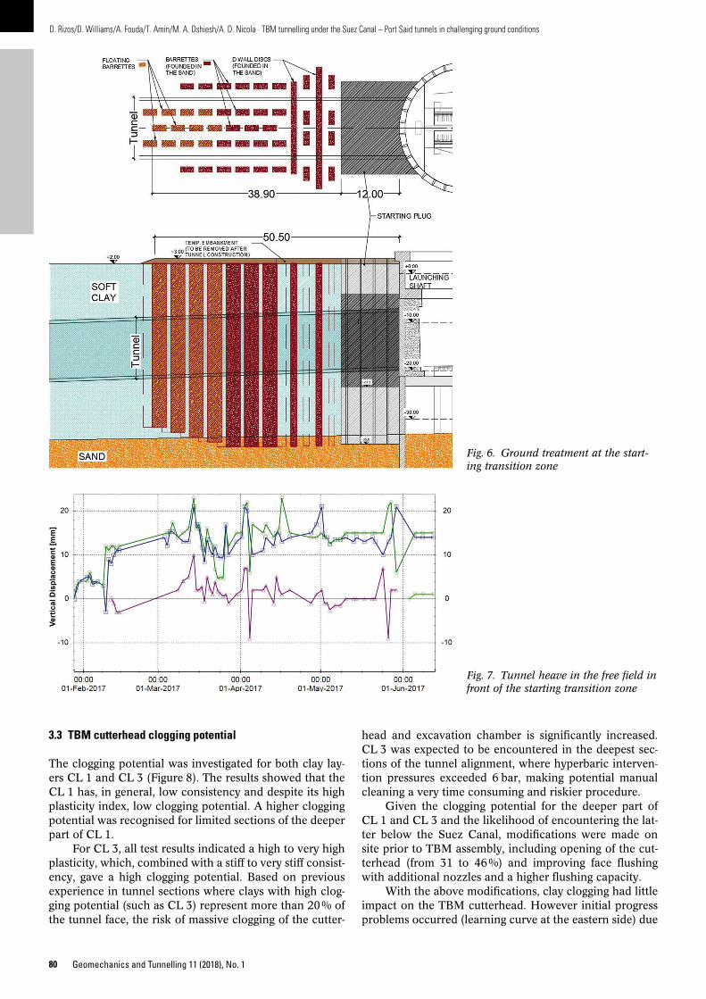
by distorting the tunnel tube in the longitudinal direction, causing sliding and an unacceptable gap opening between the rings of > 10 mm, if no measures were applied. Such a gap would adversely impact the lining watertightness with severe consequences for the durability and serviceability of the tubes. Draining of the CL 1 (due to loss of watertightness) could thus also cause uncontrolled settlement due to clay consolidation. To mitigate this, a transition zone was constructed, consisting of a system of plastic concrete diaphragm walls and barrettes appropriately distributed to provide a gradual stiffness gradient of the tunnelsoil. Figure 6 shows the optimized transition zone at the launching shafts (similar for the reception shafts). Such a configuration allows smoother deformation and curvature of the segmental lining tube in the longitudinal direction, which distributes the gap opening in more than one circumferential joint.
In addition, to mitigate geotechnical model uncertainties, a thorough sensitivity analysis was performed with respect to the soil parameters, the constitutive models and the possible soil creep effect. The results demonstrated that the main design assumptions are sufficiently conservative and resulted in upper limit values of heave. Figure 7 illustrates the recorded vertical deformation of the south tunnel tube, with only 15 mm heave occurring and no ongoing deformation for the last six months. This short term heave is less than the corresponding calculated figure. The longer term behaviour of the soiltunnel system will be monitored until commissioning using the 3D targets, extensometers and vibrating wire piezometers. The requirements for longterm monitoring will be determined based on these results.
3.2.3 TBM tilting
The soft clay presented a potential risk of TBM tilting, especially since the tunnel invert at the launching area was only 22.5 m deep where the clay is still soft. The tilting potential was checked for both normal operation and during any unforeseen stoppage. The risk of tilting was exacerbated given the tunnel drives launched with a downhill gradient of 3.3 %. The transition zone ground improvement at the launching shafts extended to 50 m ahead of the shaft and contributed to the distribution and support of the weight of the shield. Outside this zone, it was verified that the submerged weight is very small during normal operation, while for unforeseen stoppages, tilting could be prevented if only 50 % slurry drawdown is allowed. The latter is also constrained by the blowout check verification in the low overburden sections.
3.2.4 Surface development exclusions above the tunnels
Due to the sensitive nature of the CL 1, any future infrastructure or building development above the tunnels could cause ground movement and consequent unacceptable tunnel deformation. To prevent this, an exclusion zone has been defined, within which any proposed future development will be subject to careful studies to verify any impact on the tunnels.
part of the tunnel drives, in the CL 1 where the methane content was lower.
The adoption of strict working practices and enhanced gas monitoring were applied during the entire tunnel drives. In regard to TBM cutterhead interventions, the risk from methane gas was carefully evaluated and the use of safe havens and free air interventions minimized the risk. For the hyperbaric interventions, intensive gas monitoring and the venting of the gas through boreholes controlled the risk to acceptable levels.
3.2 Very soft clay
The upper CL 1 clay layer is a very soft clay for the first 12 to 15 m and gradually becomes stiffer with depth.
3.2.1 CL 1 consolidation status
In addition to the very low mechanical properties, a major concern was the consolidation status, i.e. underconsolidated (UC), normally consolidated (NC) or overconsolidated. The consolidation status could impact significantly on the design concept in terms of expected ground deformation (creep) and therefore tunnel structure behaviour in the short and long terms.
Relatively recent dredging and dumping of material on the east bank of the Suez Canal was found to have influenced the consolidation status of the clay. In addition, it was known from construction in the nearby Port Said port area that the clay is in general under to normally consolidated with resulting ongoing creep deformation. Therefore, a comprehensive investigation program was carried out to verify the clay status, with laboratory testing and numerous insitu investigations including CPTU 100 % dissipation tests and the installation of a large number of Vibrating Wire Piezometers (VWP). This campaign concluded that the CL 1 clay is underconsolidated for 200 m from the eastern bank, while for the remainder of the drives it is normally consolidated. Fortunately, in the UC clay section adjacent to the canal, the tunnel tubes are within the SL 2 sand layer and therefore there is no direct impact on the tunnel structure. SH 4, part of which is within the UC CL1, was studied and measures were taken to compensate the significant negative skin friction and avoid development of long term settlement.
3.2.2 Differential ground movements
The response of the tunnel structure to potential differential movements between the „hard points“ (e.g. the launch/reception shaft and the safe havens) and the free field, where the tunnel is effectively „floating“ in the soft clay, presents a major engineering risk. The high stiffness contrast between the launching shaft, founded in the denser SL 2 sand, and the very soft clay has a significant impact on the segmental lining. Analysis indicated that the expected tunnel lining heave (due to uplift forces and the long term dissipation of the pore pressures generated by the tunnelling) would be about 60 mm only a few metres from the shaft. This significant movement would be detrimental to the segmental lining
80 Geomechanics and Tunnelling 11 (2018), No. 1
D. Rizos/D. Williams/A. Fouda/T. Amin/M. A. Dshiesh/A. D. Nicola · TBM tunnelling under the Suez Canal – Port Said tunnels in challenging ground conditions
head and excavation chamber is significantly increased. CL 3 was expected to be encountered in the deepest sections of the tunnel alignment, where hyperbaric intervention pressures exceeded 6 bar, making potential manual cleaning a very time consuming and riskier procedure.
Given the clogging potential for the deeper part of CL 1 and CL 3 and the likelihood of encountering the latter below the Suez Canal, modifications were made on site prior to TBM assembly, including opening of the cutterhead (from 31 to 46 %) and improving face flushing with additional nozzles and a higher flushing capacity.
With the above modifications, clay clogging had little impact on the TBM cutterhead. However initial progress problems occurred (learning curve at the eastern side) due
3.3 TBM cutterhead clogging potential
The clogging potential was investigated for both clay layers CL 1 and CL 3 (Figure 8). The results showed that the CL 1 has, in general, low consistency and despite its high plasticity index, low clogging potential. A higher clogging potential was recognised for limited sections of the deeper part of CL 1.
For CL 3, all test results indicated a high to very high plasticity, which, combined with a stiff to very stiff consistency, gave a high clogging potential. Based on previous experience in tunnel sections where clays with high clogging potential (such as CL 3) represent more than 20 % of the tunnel face, the risk of massive clogging of the cutter
Fig. 6. Ground treatment at the start-ing transition zone
Fig. 7. Tunnel heave in the free field in front of the starting transition zone

81Geomechanics and Tunnelling 11 (2018), No. 1
D. Rizos/D. Williams/A. Fouda/T. Amin/M. A. Dshiesh/A. D. Nicola · TBM tunnelling under the Suez Canal – Port Said tunnels in challenging ground conditions
To minimize the possibility of TBM stops under the canal, extensive cutterhead maintenance was carried out at SH 4 (approx. 70 m before the canal) along with all cables being extended in advance to avoid plant stoppages.
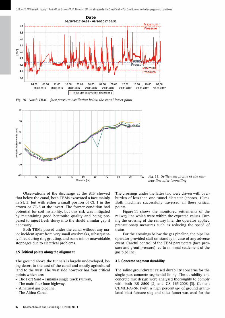
During excavation below the canal, the operation team encountered inevitable excavation chamber pressure peaks during pipe extension. To minimize these peaks, the slurry level was maintained at the manlock access level, while the evacuated slurry was discharged directly to the slurry treatment plant (STP). Figure 10 shows the oscillation of the actual face pressure of the TBM 1 (north) with fluctuation around the target value being occasionally higher than 10 kPa, but in general within the limits. No slurry blowout or face instability was recorded during the passage below the canal.
During the short stoppages for ring building, settlement of sand particles caused a blockage of the opening in the submerged wall, resulting in slight pressure spikes when excavation was resumed since the slurry was supplied to the chamber but the discharge line was temporarily blocked. To prevent this, prior to advancing the TBM, the cutterhead was rotated to mix the settled sand particles and unblock the opening. Other small pressure spikes occurred during TBM standstill due to small leakages from the feed pipe valves.
to the STP blockage of the screens, which were upgraded resulting in improved progress in the clays on the western side.
3.4 Tunnel drive below the Suez Canal
A major concern was the geological uncertainty given the lack of site investigation data below the canal. This, along with the presence of methane gas, the abrasiveness of the SL 2 and implications for tool wear, and the relatively low cover to the canal bed, were all considered carefully in the design and in the TBM operational parameters.
The recent bathymetric survey revealed the canal bed is 2 m deeper than anticipated during the finalization of the tunnel alignment – the cover below the canal being 18 m rather than the assumed 20 m. This resulted in a maximum allowed slurry pressure very close to the minimum required for face stability. Figure 9 shows the very small bandwidth of the design operational parameters with the minimum pressure at the upper pressure cell equal to 472 kPa and the maximum allowed pressure of 502 kPa (540 kPa with a reduced safety factor). Clearly careful control of the face pressure was required and special training sessions held to prepare the TBM operation team.
Fig. 8. Clogging potential of CL 1 and CL 3 (according to [4])
Fig. 9. Face pressure along the tunnel alignment – minimum required; maximum allowed; target value for safe operation
82 Geomechanics and Tunnelling 11 (2018), No. 1
D. Rizos/D. Williams/A. Fouda/T. Amin/M. A. Dshiesh/A. D. Nicola · TBM tunnelling under the Suez Canal – Port Said tunnels in challenging ground conditions
The crossings under the latter two were driven with overburden of less than one tunnel diameter (approx. 10 m). Both machines successfully traversed all these critical points.
Figure 11 shows the monitored settlements of the railway line which were within the expected values. During the crossing of the railway line, the operator applied precautionary measures such as reducing the speed of trains.
For the crossings below the gas pipeline, the pipeline operator provided staff on standby in case of any adverse event. Careful control of the TBM parameters (face pressure and grout pressure) led to minimal settlement of the gas pipeline.
3.6 Concrete segment durability
The saline groundwater raised durability concerns for the singlepass concrete segmental lining. The durability and concrete mix design were analysed thoroughly to comply with both BS 8500 [2] and CS 1632008 [3]. Cement CEMIIIA+SR (with a high percentage of ground granulated blast furnace slag and silica fume) was used for the
Observations of the discharge at the STP showed that below the canal, both TBMs excavated a face mainly in SL 2, but with either a small portion of CL 1 in the crown or CL 3 at the invert. The former condition had potential for soil instability, but this risk was mitigated by maintaining good bentonite quality and being prepared to inject fresh slurry into the shield annular gap if necessary.
Both TBMs passed under the canal without any major incident apart from very small overbreaks, subsequently filled during ring grouting, and some minor unavoidable stoppages due to electrical problems.
3.5 Critical points along the alignment
The ground above the tunnels is largely undeveloped, being desert to the east of the canal and mostly agricultural land to the west. The west side however has four critical points which are:– The Port Said – Ismailia single track railway,– The main fourlane highway,– A natural gas pipeline,– The Altina Canal.
Fig. 10. North TBM – face pressure oscillation below the canal lower point
Fig. 11. Settlement profile of the rail-way line after tunnelling
83Geomechanics and Tunnelling 11 (2018), No. 1
D. Rizos/D. Williams/A. Fouda/T. Amin/M. A. Dshiesh/A. D. Nicola · TBM tunnelling under the Suez Canal – Port Said tunnels in challenging ground conditions
chines (and the STP) at this stop and carried out under atmospheric conditions.
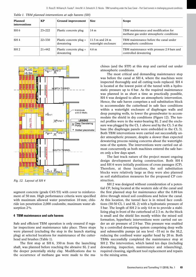
The most critical and demanding maintenance stop was before the canal at SH 4, where the machines were inspected thoroughly and all cutting tools replaced. SH 4 is located at the lowest point of the tunnel with a hydrostatic pressure up to 6 bar. As the required maintenance was planned in as short a time as practically possible, SH 4 was designed to allow an atmospheric intervention. Hence, the safe haven comprises a soil substitution block to accommodate the cutterhead in safe face conditions within a watertight enclosure of diaphragm walls and deep pumping wells, to lower the groundwater to accommodate the shield in dry conditions (Figure 12). The tunnel profiles were in the waterbearing SL 2 and the enclosure was plugged by the CL 1 above and by the CL 3 at the base (the diaphragm panels were embedded in the CL 3). Both TBM interventions were carried out successfully under atmospheric pressure, despite a slower than expected dewatering process raising concerns about the watertightness of the system. The interventions were carried out almost concurrently as both machines entered the safe haven only a few days apart.
The fast track nature of the project meant ongoing design development during construction. Both SH 4 and SH 6 were initially positions of cross passages (CP). Therefore, at these locations, the soil substitution blocks were relatively large as they were also planned as soil stabilization measures for the proposed CP construction.
SH 2 was designed without consideration of a potential CP, being located at the western side of the canal and the first planned stop for maintenance after the 0.89 km drive through mixed soil conditions and below the canal. At this location, the tunnel face is in mixed face conditions (5050 CL 1 and SL 2) with a hydrostatic pressure of 5 bar. The length of SH 2 is only 4.6 m to provide a stabilizing plug in front of the cutterhead of 2.3 m. As the block is small and the shield lies mostly within the mixed soil formation, hyperbaric interventions were carried out under an air pressure of 2.9 bar. This pressure was enabled by a controlled dewatering system comprising deep wells and submersible pumps (at sea level –55 m) in the SL2, reducing the confined water aquifer head by 20 m. Both TBMs successfully completed the maintenance stop at SH 2. The intervention, which lasted ten days (including dewatering, inspection, maintenance and relaunching), required cleaning, significant tool replacement and repairs to the mixing arms.
segment concrete (grade C45/55) with cover to reinforcement of 50 mm. High performance criteria were specified with maximum allowed water penetration 10 mm; chloride ion penetration 2,000 coulombs; maximum water absorption 2 %.
4 TBM maintenance and safe havens
Safe and efficient TBM operation is only ensured if regular inspections and maintenance take place. Three stops were planned (excluding the stop in the launch starting plug) at selected locations for maintenance of the cutterhead and brushes (Table 1).
The first stop at SH 6, 350 m from the launching shaft, was planned before reaching the abrasive SL 2 and the deeper potentially sticky clay. Modifications due to the occurrence of methane gas were made to the ma
Table 1. TBM planned interventions at safe havens (SH)
Planned interventions
KP Ground improvement Size Scope
SH 6 23+222 Plastic concrete plug 14 m TBM maintenance and modification for methane gas under atmospheric conditions
SH 4 22+330 Plastic concrete plug + dewatering
11.5 m and 24 m watertight enclosure
TBM maintenance before the canal under atmospheric conditions
SH 2 21+442 Plastic concrete plug + dewatering
4.6 m TBM maintenance with pressure 2.9 bars and controlled dewatering
Fig. 12. Layout of SH 4
84 Geomechanics and Tunnelling 11 (2018), No. 1
D. Rizos/D. Williams/A. Fouda/T. Amin/M. A. Dshiesh/A. D. Nicola · TBM tunnelling under the Suez Canal – Port Said tunnels in challenging ground conditions
control deformation of the frozen ring. The most critical area is adjacent to the tunnel tube, where deformation must be limited to avoid damage to the freezing pipes. The face will also be frozen to enhance stability and to reduce face core extrusion. Halfmoon steel frames will be installed to support the tunnel segments and allow free traffic movement in the tunnel during cross passage construction. The permanent lining will be installed before the freezing is turned off.
6 Conclusion
The tunnels, at 13.05 m diameter, are among the largest diameter tunnels undertaken in the Middle East/North Africa region. The successful conclusion of both tunnel drives, carried out under difficult conditions and in under 30 months from preliminary design, is a testament to the robust approach taken to both the design and construction processes (Figure 14). The variety of tunnelling challenges encountered required a flexible and dynamic approach from all parties involved. This is evidenced by the various design and construction risk mitigation measures (including those for methane gas, very soft clay, clogging of the cutterhead and hyperbaric interventions) evaluated and successfully implemented.
References
[1] PST: Internal Design Documents. SenerAmberg and Subcontractors.
[2] BS 85001: Concrete – Complementary British Standard to BS EN 2061: Method of specifying and guidance for the specifier. British Standards Institution, London, 2006.
[3] CS 163: Guide to the design of concrete structures in the Arabian Peninsula. National Building Specification, 2008.
[4] Hollmann, F., Thewes, M.: Assessment method for clay clogging and disintegration of fines in mechanised tunnelling. TUST 37 (2013), pp. 96–106.
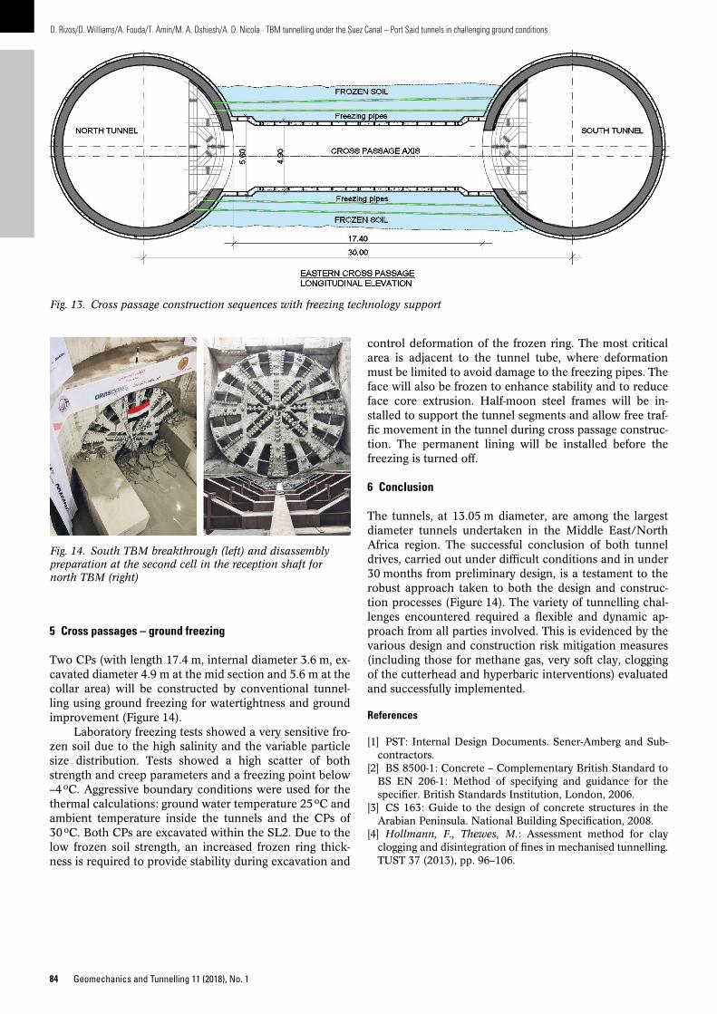
5 Cross passages – ground freezing
Two CPs (with length 17.4 m, internal diameter 3.6 m, excavated diameter 4.9 m at the mid section and 5.6 m at the collar area) will be constructed by conventional tunnelling using ground freezing for watertightness and ground improvement (Figure 14).
Laboratory freezing tests showed a very sensitive frozen soil due to the high salinity and the variable particle size distribution. Tests showed a high scatter of both strength and creep parameters and a freezing point below –4 oC. Aggressive boundary conditions were used for the thermal calculations: ground water temperature 25 oC and ambient temperature inside the tunnels and the CPs of 30 oC. Both CPs are excavated within the SL2. Due to the low frozen soil strength, an increased frozen ring thickness is required to provide stability during excavation and
Fig. 13. Cross passage construction sequences with freezing technology support
Fig. 14. South TBM breakthrough (left) and disassembly preparation at the second cell in the reception shaft for north TBM (right)
85Geomechanics and Tunnelling 11 (2018), No. 1
D. Rizos/D. Williams/A. Fouda/T. Amin/M. A. Dshiesh/A. D. Nicola · TBM tunnelling under the Suez Canal – Port Said tunnels in challenging ground conditions
Dr. Tarek AminNile City South Tower,2005 A Conriche El Nil,Cairo – Egypt [email protected]
Mohamed AboudshieshArab Contractors34 Adly Steet, Cairo, [email protected]
Anis Dimitry NicolaNile City South Tower,2005 A Conriche El Nil,Cairo, Egypt [email protected]
Dimitrios Rizos MScOrascom ConstructionNile City South Tower,2005 A Conriche El Nil,Cairo, Egypt [email protected]
Derek WilliamsSystra Egypt BranchWorld Trade Center Complex Buildings1191 Corniche El NileCairo, Egypt [email protected]
Dr. Ahmed FoudaEngineering Authority Armed Forces,8 Ehsan Abd Elkodous, Heliopolis,Cairo, [email protected]
![Author(s): Fouda, IM (Fouda, I. M.)[ 1] ; Oraby, AH (Oraby ...scimfac.mans.edu.eg/arabic/authorguide/Physicsdepartment/AHMED… · Author(s): Fouda, IM; Shabana, HM Source: JOURNAL](https://img.pdfslide.net/doc/110x75/5f04f2d57e708231d410818d/authors-fouda-im-fouda-i-m-1-oraby-ah-oraby-authors-fouda.jpg)