Embed Size (px)
Citation preview
TB-IM Rev. 09/15 (BK-TB INSTALL)
T E C H N I - B E A M D I V I N G B O A R DT E C H N I - S P R I N G S T E E L O R
F I B E R G L A S S S T A N DAssembly & Installation Instructions
3 0 5 0 S . A L V E R N O N W A Y • T U C S O N , A Z 8 5 7 1 35 2 0 . 7 9 0 . 7 0 4 0 • 8 0 0 . 7 3 7 . 5 3 8 6 • F A X 5 2 0 . 7 9 0 . 7 1 2 7
i n t e r - f a b . c o m
ATTENTION
INSTALLERS:
Please deliver and
review this manual with
HOMEOWNER.
Visit inter-fab.com to view our installation help video. (Video does NOT replace installation instructions.)
WARNING: IMPORTANT INSTALLATION INFORMATIONThe installation of this product should be done only by a licensedand professional installer. Installation should be done strictlyin conformance with all local building codes, electrical codesand other building and safety laws and regulations. Amongother things, that your installer should carefully analyze theneed to bond the product to prevent an electrical hazard.Failure to properly install this product could result in a dangerouscondition, including but not limited to electrical and or structuralhazards. Inter-fab, Inc. disclaims all liability arising from theinstallation and the user assumes all risk associated with theinstallation.
For Technical Support or Assistance, Contact Customer Service at:
INTER-FAB, INC.3050 S. ALVERNON WAY
TUCSON, AZ 85713(800) 737-5386
or visit: www.inter-fab.com
To obtain complete copies of the ANSI/APSP/ICC-5 2011Standard for Residential Inground Pools or to obtain copies ofthe “Plan Your Dive, Steer Up” or “The Sensible Way to EnjoyYour Inground Swimming Pool” contact:
The Association of Pool & Spa Professionals (APSP)2111 Eisenhower Ave.Alexandria, VA 22314
(703) 838-0083
or visit: www.theapsp.org
TB-IM Rev. 09/15 (BK-TB INSTALL)
I N S T A L L A T I O N M A N U A L T E C H N I - S P R I N G ™
1TB-IM Rev. 09/15 (BK-TB INSTALL)
TABLE OF CONTENTS:
Safety First ............................................................................2
Intended Use Instructions ........................................................3
Important Notices to the Installer..............................................4
Minimum Diving Water Envelope Information...............................5
Techni-Spring (Steel Base) Placement ........................................6
Techni-Spring (Fiberglass Base) Placement .................................7
Techni-Beam Board Dimensions & Fulcrum Settings ....................8
Techni-Spring Jig Information ....................................................8
Installation Instructions ............................................................9
Techni-Spring (Steel Base) Exploded View & Parts List................10
Techni-Spring (Fiberglass Base) Exploded View & Parts List.........11
Paver Kit Information.............................................................12
Article 5 Extracted from ANSI/APSP/ICC-5 2011 ...............13-16
Pages for Notes ...................................................................17
Inter-Fab Limited Warranty.....................................................18
I N S T A L L A T I O N M A N U A L T E C H N I - S P R I N G ™
2TB-IM Rev. 09/15 (BK-TB INSTALL)
This Inter-Fab diving board and stand shall be installed only by a professional swimming pool contractoror with the direct supervision of a licensed professional, engineer or architect. Diving boards maybe installed only on residential inground swimming pools properly designed for their use.
Diving boards that are improperly installed can be very dangerous to the user resulting in possibleserious head and/or spinal column injury, including the paralysis or death of the user.
It is very important that this diving board and/or stand be installed only on a pool that is built instrict accordance with the American National Standard for Residential Inground Swimming Pools(ANSI/APSP/ICC-5 2011) and in strict accordance with the included INTER-FAB RESIDENTIALPOOL SPECIFICATIONS TABLE 2. Under no circumstances can this diving board and/or stand beinstalled on any above ground or on-ground swimming pool.
In addition to the above standard and referenced table, these installation instructions provided byInter-Fab, Inc. must be diligently followed.
It is also important that any and all warnings provided with the diving board be strictly adhered toand posted in a conspicuous location. If not provided or they are misplaced, please purchasewarning signs from your pool contractor or professional pool supply store and post them in a locationthat the users of the diving board can clearly see.
SAFETY FIRST!
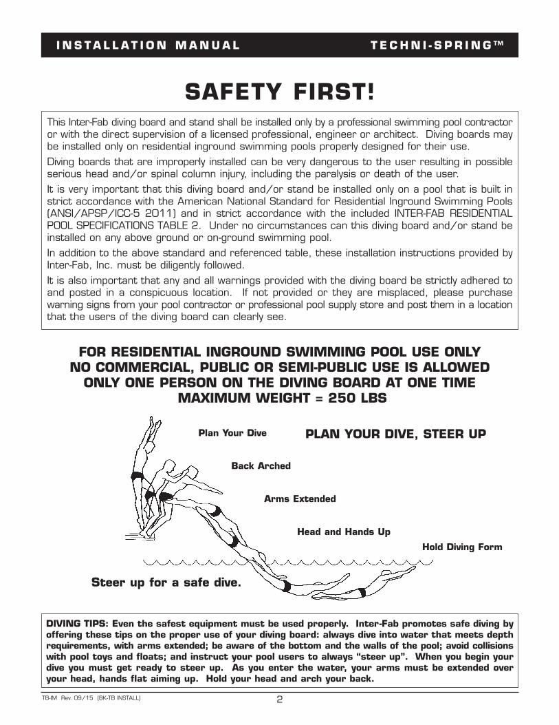
DIVING TIPS: Even the safest equipment must be used properly. Inter-Fab promotes safe diving byoffering these tips on the proper use of your diving board: always dive into water that meets depthrequirements, with arms extended; be aware of the bottom and the walls of the pool; avoid collisionswith pool toys and floats; and instruct your pool users to always “steer up”. When you begin yourdive you must get ready to steer up. As you enter the water, your arms must be extended overyour head, hands flat aiming up. Hold your head and arch your back.
FOR RESIDENTIAL INGROUND SWIMMING POOL USE ONLYNO COMMERCIAL, PUBLIC OR SEMI-PUBLIC USE IS ALLOWED
ONLY ONE PERSON ON THE DIVING BOARD AT ONE TIMEMAXIMUM WEIGHT = 250 LBS
Plan Your Dive
Back Arched
Arms Extended
Head and Hands Up
Hold Diving Form
Steer up for a safe dive.
PLAN YOUR DIVE, STEER UP
I N S T A L L A T I O N M A N U A L T E C H N I - S P R I N G ™
3TB-IM Rev. 09/15 (BK-TB INSTALL)
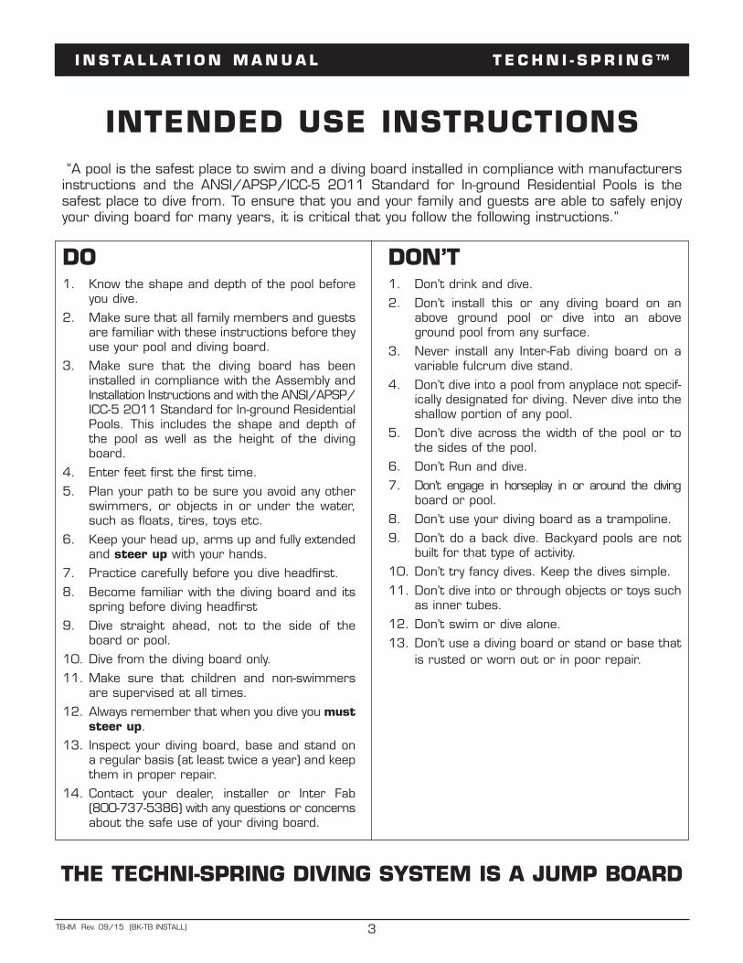
“A pool is the safest place to swim and a diving board installed in compliance with manufacturersinstructions and the ANSI/APSP/ICC-5 2011 Standard for In-ground Residential Pools is thesafest place to dive from. To ensure that you and your family and guests are able to safely enjoyyour diving board for many years, it is critical that you follow the following instructions.”
INTENDED USE INSTRUCTIONS
DO1. Know the shape and depth of the pool before
you dive.
2. Make sure that all family members and guestsare familiar with these instructions before theyuse your pool and diving board.
3. Make sure that the diving board has beeninstalled in compliance with the Assembly andInstallation Instructions and with the ANSI/APSP/ICC-5 2011 Standard for In-ground ResidentialPools. This includes the shape and depth ofthe pool as well as the height of the divingboard.
4. Enter feet first the first time.
5. Plan your path to be sure you avoid any otherswimmers, or objects in or under the water,such as floats, tires, toys etc.
6. Keep your head up, arms up and fully extendedand steer up with your hands.
7. Practice carefully before you dive headfirst.
8. Become familiar with the diving board and itsspring before diving headfirst
9. Dive straight ahead, not to the side of theboard or pool.
10. Dive from the diving board only.
11. Make sure that children and non-swimmersare supervised at all times.
12. Always remember that when you dive you muststeer up.
13. Inspect your diving board, base and stand ona regular basis (at least twice a year) and keepthem in proper repair.
14. Contact your dealer, installer or Inter Fab(800-737-5386) with any questions or concernsabout the safe use of your diving board.
DON’T1. Don’t drink and dive.
2. Don’t install this or any diving board on anabove ground pool or dive into an aboveground pool from any surface.
3. Never install any Inter-Fab diving board on avariable fulcrum dive stand.
4. Don’t dive into a pool from anyplace not specif-ically designated for diving. Never dive into theshallow portion of any pool.
5. Don’t dive across the width of the pool or tothe sides of the pool.
6. Don’t Run and dive.
7. Don’t engage in horseplay in or around the divingboard or pool.
8. Don’t use your diving board as a trampoline.
9. Don’t do a back dive. Backyard pools are notbuilt for that type of activity.
10. Don’t try fancy dives. Keep the dives simple.
11. Don’t dive into or through objects or toys suchas inner tubes.
12. Don’t swim or dive alone.
13. Don’t use a diving board or stand or base thatis rusted or worn out or in poor repair.
THE TECHNI-SPRING DIVING SYSTEM IS A JUMP BOARD
I N S T A L L A T I O N M A N U A L T E C H N I - S P R I N G ™
4TB-IM Rev. 09/15 (BK-TB INSTALL)
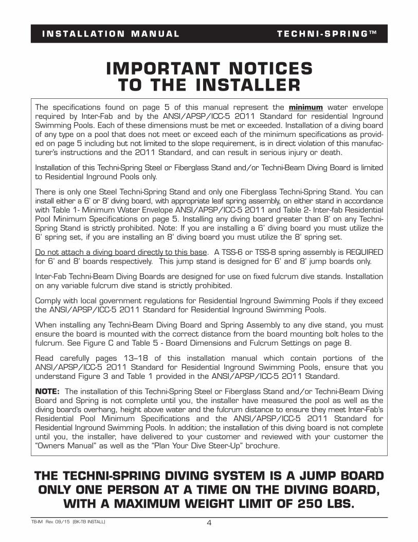
The specifications found on page 5 of this manual represent the minimum water enveloperequired by Inter-Fab and by the ANSI/APSP/ICC-5 2011 Standard for residential IngroundSwimming Pools. Each of these dimensions must be met or exceeded. Installation of a diving boardof any type on a pool that does not meet or exceed each of the minimum specifications as provid-ed on page 5 including but not limited to the slope requirement, is in direct violation of this manufac-turer’s instructions and the 2011 Standard, and can result in serious injury or death.
Installation of this Techni-Spring Steel or Fiberglass Stand and/or Techni-Beam Diving Board is limitedto Residential Inground Pools only.
There is only one Steel Techni-Spring Stand and only one Fiberglass Techni-Spring Stand. You caninstall either a 6’ or 8’ diving board, with appropriate leaf spring assembly, on either stand in accordancewith Table 1- Minimum Water Envelope ANSI/APSP/ICC-5 2011 and Table 2- Inter-fab ResidentialPool Minimum Specifications on page 5. Installing any diving board greater than 8’ on any Techni-Spring Stand is strictly prohibited. Note: If you are installing a 6’ diving board you must utilize the6’ spring set, if you are installing an 8’ diving board you must utilize the 8’ spring set.
Do not attach a diving board directly to this base. A TSS-6 or TSS-8 spring assembly is REQUIREDfor 6’ and 8’ boards respectively. This jump stand is designed for 6’ and 8’ jump boards only.
Inter-Fab Techni-Beam Diving Boards are designed for use on fixed fulcrum dive stands. Installationon any variable fulcrum dive stand is strictly prohibited.
Comply with local government regulations for Residential Inground Swimming Pools if they exceedthe ANSI/APSP/ICC-5 2011 Standard for Residential Inground Swimming Pools.
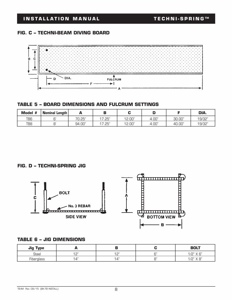
When installing any Techni-Beam Diving Board and Spring Assembly to any dive stand, you mustensure the board is mounted with the correct distance from the board mounting bolt holes to thefulcrum. See Figure C and Table 5 - Board Dimensions and Fulcrum Settings on page 8.
Read carefully pages 13–18 of this installation manual which contain portions of theANSI/APSP/ICC-5 2011 Standard for Residential Inground Swimming Pools, ensure that youunderstand Figure 3 and Table 1 provided in the ANSI/APSP/ICC-5 2011 Standard.
NOTE: The installation of this Techni-Spring Steel or Fiberglass Stand and/or Techni-Beam DivingBoard and Spring is not complete until you, the installer have measured the pool as well as thediving board’s overhang, height above water and the fulcrum distance to ensure they meet Inter-Fab’sResidential Pool Minimum Specifications and the ANSI/APSP/ICC-5 2011 Standard forResidential Inground Swimming Pools. In addition; the installation of this diving board is not completeuntil you, the installer, have delivered to your customer and reviewed with your customer the“Owners Manual” as well as the “Plan Your Dive Steer-Up” brochure.
IMPORTANT NOTICES TO THE INSTALLER
THE TECHNI-SPRING DIVING SYSTEM IS A JUMP BOARDONLY ONE PERSON AT A TIME ON THE DIVING BOARD,
WITH A MAXIMUM WEIGHT LIMIT OF 250 LBS.
I N S T A L L A T I O N M A N U A L T E C H N I - S P R I N G ™
5TB-IM Rev. 09/15 (BK-TB INSTALL)
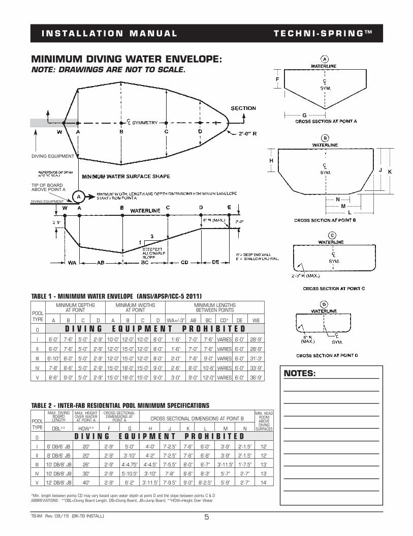
MINIMUM DIVING WATER ENVELOPE:NOTE: DRAWINGS ARE NOT TO SCALE.
NOTES:
DIVING EQUIPMENT
TIP OF BOARDABOVE POINT A
D I V I N G E Q U I P M E N T P R O H I B I T E D
D I V I N G E Q U I P M E N T P R O H I B I T E DA B C D A B C D WA+/-3” AB BC CD* DE WE
0
I 6’-0” 7’-6” 5’-0” 2’-9” 10’-0” 12’-0” 10’-0” 8’-0” 1’-6” 7’-0” 7’-6” VARIES 6’-0” 28’-9”
II 6’-0” 7’-6” 5’-0” 2’-9” 12’-0” 15’-0” 12’-0” 8’-0” 1’-6” 7’-0” 7’-6” VARIES 6’-0” 28’-9”
III 6’-10” 8’-0” 5’-0” 2’-9” 12’-0” 15’-0” 12’-0” 8’-0” 2’-0” 7’-6” 9’-0” VARIES 6’-0” 31’-3”
IV 7’-8” 8’-6” 5’-0” 2’-9” 15’-0” 18’-0” 15’-0” 9’-0” 2’-6” 8’-0” 10’-6” VARIES 6’-0” 33’-9”
V 8’-6” 9’-0” 5’-0” 2’-9” 15’-0” 18’-0” 15’-0” 9’-0” 3’-0” 9’-0” 12’-0” VARIES 6’-0” 36’-9”
POOLTYPE
MINIMUM DEPTHS AT POINT
MINIMUM WIDTHS AT POINT
MINIMUM LENGTHS BETWEEN POINTS
TABLE 1 - MINIMUM WATER ENVELOPE (ANSI/APSP/ICC-5 2011)
DBL** HOW** F G H J K L M N
0
I 6’ DB/6’ JB 20” 2’-9” 5’-0” 4’-0” 7’-2.5” 7’-6” 6’-0” 3’-9” 2’-1.5” 12’
II 8’ DB/6’ JB 20” 2’-9” 3’-10” 4’-2” 7’-2.5” 7’-6” 6’-8” 3’-9” 2’-1.5” 12’
III 10’ DB/8’ JB 26” 2’-9” 4’-4.75” 4’-4.5” 7’-5.5” 8’-0” 6’-7” 3’-11.5” 1’-7.5” 13’
IV 10’ DB/8’ JB 30” 2’-9” 5’-10.5” 3’-10” 7’-8” 8’-6” 8’-3” 5’-7” 2’-7” 13’
V 12’ DB/8’ JB 40” 2’-9” 6’-2” 3’-11.5” 7’-9.5” 9’-0” 8’-2.5” 5’-9” 2’-7” 14’
POOLTYPE
MAX. DIVINGBOARDLENGTH
MAX. HEIGHTOVER WATERAT POINT A
CROSS SECTIONALDIMENSIONS AT
POINT A CROSS SECTIONAL DIMENSIONS AT POINT B
TABLE 2 - INTER-FAB RESIDENTIAL POOL MINIMUM SPECIFICATIONSMIN. HEADROOMABOVE DIVING
SURFACES
*Min. length between points CD may vary based upon water depth at point D and the slope between points C & DABBREVIATIONS: **DBL=Diving Board Length; DB=Diving Board; JB=Jump Board; **HOW=Height Over Water
F
G
HJ K
NML
DIVING EQUIPMENT
I N S T A L L A T I O N M A N U A L T E C H N I - S P R I N G ™
6TB-IM Rev. 09/15 (BK-TB INSTALL)
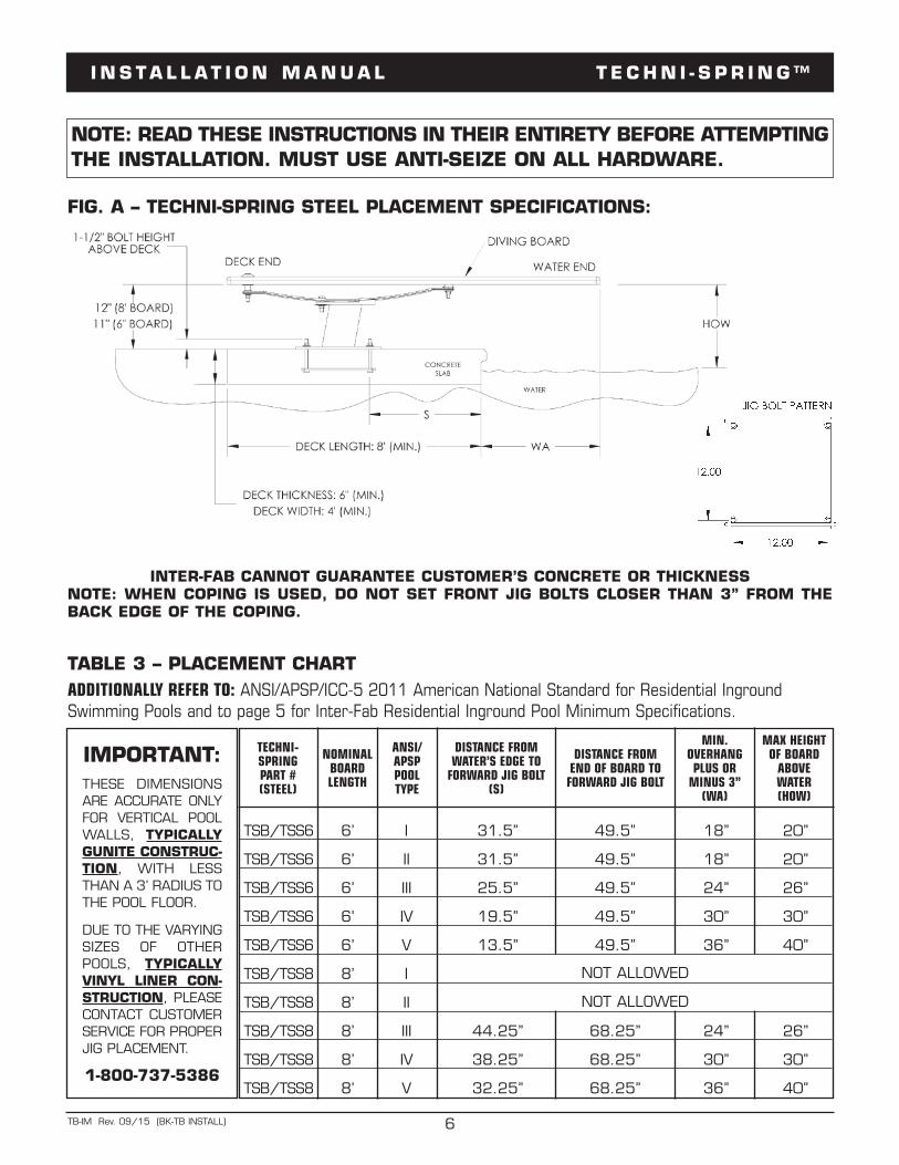
FIG. A – TECHNI-SPRING STEEL PLACEMENT SPECIFICATIONS:
TABLE 3 – PLACEMENT CHARTADDITIONALLY REFER TO: ANSI/APSP/ICC-5 2011 American National Standard for Residential IngroundSwimming Pools and to page 5 for Inter-Fab Residential Inground Pool Minimum Specifications.
INTER-FAB CANNOT GUARANTEE CUSTOMER’S CONCRETE OR THICKNESSNOTE: WHEN COPING IS USED, DO NOT SET FRONT JIG BOLTS CLOSER THAN 3” FROM THEBACK EDGE OF THE COPING.
NOTE: READ THESE INSTRUCTIONS IN THEIR ENTIRETY BEFORE ATTEMPTINGTHE INSTALLATION. MUST USE ANTI-SEIZE ON ALL HARDWARE.
IMPORTANT:THESE DIMENSIONSARE ACCURATE ONLYFOR VERTICAL POOLWALLS, TYPICALLYGUNITE CONSTRUC-TION, WITH LESSTHAN A 3’ RADIUS TOTHE POOL FLOOR.
DUE TO THE VARYINGSIZES OF OTHERPOOLS, TYPICALLYVINYL LINER CON-STRUCTION, PLEASECONTACT CUSTOMERSERVICE FOR PROPERJIG PLACEMENT.
1-800-737-5386
TECHNI-SPRINGPART #(STEEL)
NOMINALBOARDLENGTH
ANSI/APSPPOOL TYPE
DISTANCE FROM WATER’S EDGE TO FORWARD JIG BOLT
(S)
DISTANCE FROM END OF BOARD TOFORWARD JIG BOLT
MAX HEIGHTOF BOARDABOVE WATER(HOW)
TSB/TSS6 6’ I 31.5” 49.5” 18” 20”
TSB/TSS6 6’ II 31.5” 49.5” 18” 20”
TSB/TSS6 6’ III 25.5” 49.5” 24” 26”
TSB/TSS6 6’ IV 19.5” 49.5” 30” 30”
TSB/TSS6 6’ V 13.5” 49.5” 36” 40”
TSB/TSS8 8’ I
TSB/TSS8 8’ II
TSB/TSS8 8’ III 44.25” 68.25” 24” 26”
TSB/TSS8 8’ IV 38.25” 68.25” 30” 30”
TSB/TSS8 8’ V 32.25” 68.25” 36” 40”
MIN.OVERHANGPLUS ORMINUS 3”
(WA)
NOT ALLOWED
NOT ALLOWED
I N S T A L L A T I O N M A N U A L T E C H N I - S P R I N G ™
7TB-IM Rev. 09/15 (BK-TB INSTALL)
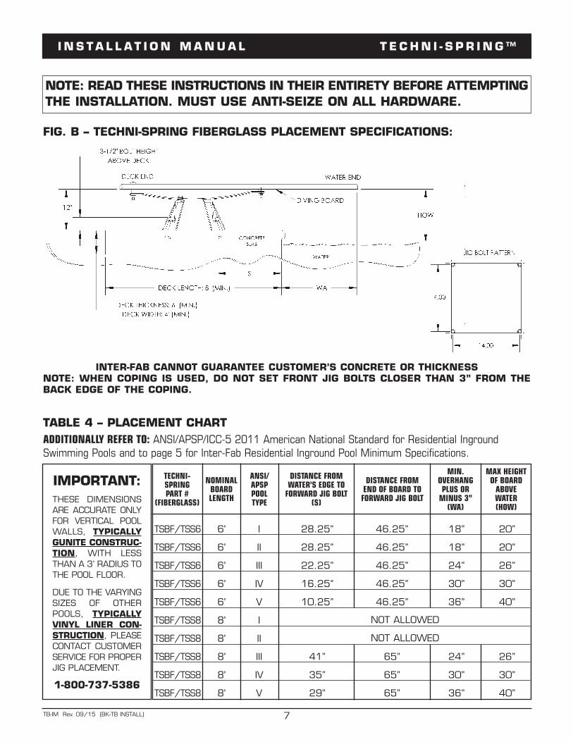
FIG. B – TECHNI-SPRING FIBERGLASS PLACEMENT SPECIFICATIONS:
TABLE 4 – PLACEMENT CHARTADDITIONALLY REFER TO: ANSI/APSP/ICC-5 2011 American National Standard for Residential IngroundSwimming Pools and to page 5 for Inter-Fab Residential Inground Pool Minimum Specifications.
INTER-FAB CANNOT GUARANTEE CUSTOMER’S CONCRETE OR THICKNESSNOTE: WHEN COPING IS USED, DO NOT SET FRONT JIG BOLTS CLOSER THAN 3” FROM THEBACK EDGE OF THE COPING.
NOTE: READ THESE INSTRUCTIONS IN THEIR ENTIRETY BEFORE ATTEMPTINGTHE INSTALLATION. MUST USE ANTI-SEIZE ON ALL HARDWARE.
IMPORTANT:THESE DIMENSIONSARE ACCURATE ONLYFOR VERTICAL POOLWALLS, TYPICALLYGUNITE CONSTRUC-TION, WITH LESSTHAN A 3’ RADIUS TOTHE POOL FLOOR.
DUE TO THE VARYINGSIZES OF OTHERPOOLS, TYPICALLYVINYL LINER CON-STRUCTION, PLEASECONTACT CUSTOMERSERVICE FOR PROPERJIG PLACEMENT.
1-800-737-5386
TECHNI-SPRINGPART #
(FIBERGLASS)
NOMINALBOARDLENGTH
ANSI/APSPPOOL TYPE
DISTANCE FROM WATER’S EDGE TO FORWARD JIG BOLT
(S)
DISTANCE FROM END OF BOARD TOFORWARD JIG BOLT
MAX HEIGHTOF BOARDABOVE WATER(HOW)
TSBF/TSS6 6' I 28.25” 46.25” 18” 20”
TSBF/TSS6 6' II 28.25” 46.25” 18” 20”
TSBF/TSS6 6' III 22.25” 46.25” 24” 26”
TSBF/TSS6 6' IV 16.25” 46.25” 30” 30”
TSBF/TSS6 6' V 10.25” 46.25” 36” 40”
TSBF/TSS8 8' I
TSBF/TSS8 8' II
TSBF/TSS8 8' III 41” 65” 24” 26”
TSBF/TSS8 8' IV 35” 65” 30” 30”
TSBF/TSS8 8' V 29” 65” 36” 40”
MIN.OVERHANGPLUS ORMINUS 3”
(WA)
NOT ALLOWED
NOT ALLOWED
I N S T A L L A T I O N M A N U A L T E C H N I - S P R I N G ™
8TB-IM Rev. 09/15 (BK-TB INSTALL)
FIG. C – TECHNI-BEAM DIVING BOARD
TABLE 5 – BOARD DIMENSIONS AND FULCRUM SETTINGS
Model # Nominal Length A B C D F DIA.
TB6 6’ 70.25” 17.25” 12.00” 4.00” 30.00” 19/32”TB8 8’ 94.00” 17.25” 12.00” 4.00” 40.00” 19/32”
TABLE 6 – JIG DIMENSIONS
Jig Type A B C BOLT
Steel 12” 12” 6” 1/2” X 6”Fiberglass 14” 14” 8” 1/2” X 8”
FIG. D – TECHNI-SPRING JIG
C
I N S T A L L A T I O N M A N U A L T E C H N I - S P R I N G ™
9TB-IM Rev. 09/15 (BK-TB INSTALL)
Techni-Spring Steel or Fiberglass Stand and/or Techni-Beam Diving BoardINSTALLATION INSTRUCTIONS
Be sure the concrete deck surrounding the anchor jig complies with the minimum dimensions asshown in Figures A & B on pages 6 & 7.
Read and understand the ANSI/APSP/ICC-5 2011 American National Standard for ResidentialInground swimming Pools and Table 1 and Table 2 on page 5 before you install Techni-spring Steelor Fiberglass Stand and/or Techni-Beam Diving Board and Spring.
The Techni-Spring four-bolt jig should be set in accordance with Table 3 on page 6 or Table 4 onpage 7. The diving board must be placed on the deep end of the pool on centerline.
The tip of the diving board must be positioned directly over Pt. A as shown on the Figures 3 on page5 and according to the ANSI/APSP/ICC-5 2011 Standard and Inter-Fab’s Residential Pool MinimumSpecifications.
Make sure the jig anchor bolts project out of the concrete deck 1-1/2” for the Steel Stand and 3-1/2”for the Fiberglass Stand with ample concrete depth below the jig in accordance with Figure A onpage 6 or Figure B on page 7. Do not install the Techni-Spring Dive system if the deck does not meetthe minimum requirements.
CHECK YOUR LOCAL ELECTRICAL CODE FOR BONDING REQUIREMENTS.
When finishing the deck surface, maintain a level deck where the jig bolts project out so the divestand makes uniform contact with the deck surface. Allow the cement to fully cure before boltingthe dive stand to the jig bolts.
Before bolting the dive stand to the jig bolts, chisel away any excess concrete that may have builtup around the jig bolts then remove the protective red and yellow rubber bolt caps.
USE ANTI-SEIZE ON ALL HARDWARE.
NOTE: When installing the Techni-Spring Fiberglass Stand, you must first attach the springs to thebase and fully tighten the nuts before placing the stand over the jig bolts, or you cannot tighten them.
Place the stand over the four jig bolts and secure according to the Hardware Instructions on pages10-11. Tighten the Stand Anchor Hex Nuts to 40-45 FT- LBS. Do not over tighten.
Once the Techni-Spring Stand is properly secured to the four jig bolts, then place the springs overthe stand and secure according to the Hardware Instructions on pages 10-11. Tighten the SpringMounting Hex Nuts to 40-45 FT- LBS. Do not over tighten.
Once the Techni-Spring Springs are properly secured to the stand then secure diving board accordingto the Hardware Instructions on pages 10-11. Tighten the Board Mounting Hex Nuts to 20-25 FT- LBS.Do not over tighten.
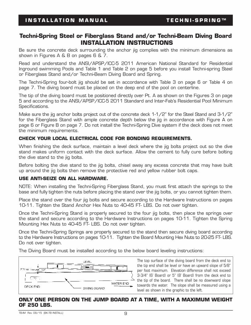
The Diving Board must be installed according to the below board leveling instructions:
The top surface of the diving board from the deck end tothe tip end shall be level or have an upward slope of 5/8"per foot maximum. Elevation difference shall not exceed3-3/4" (6’ Board) or 5” (8’ Board) from the deck end tothe tip of the board. There shall be no downward slopetowards the water. The slope shall be measured using alevel as shown in the graphic to the left.
ONLY ONE PERSON ON THE JUMP BOARD AT A TIME, WITH A MAXIMUM WEIGHTOF 250 LBS.
I N S T A L L A T I O N M A N U A L T E C H N I - S P R I N G ™
10TB-IM Rev. 09/15 (BK-TB INSTALL)
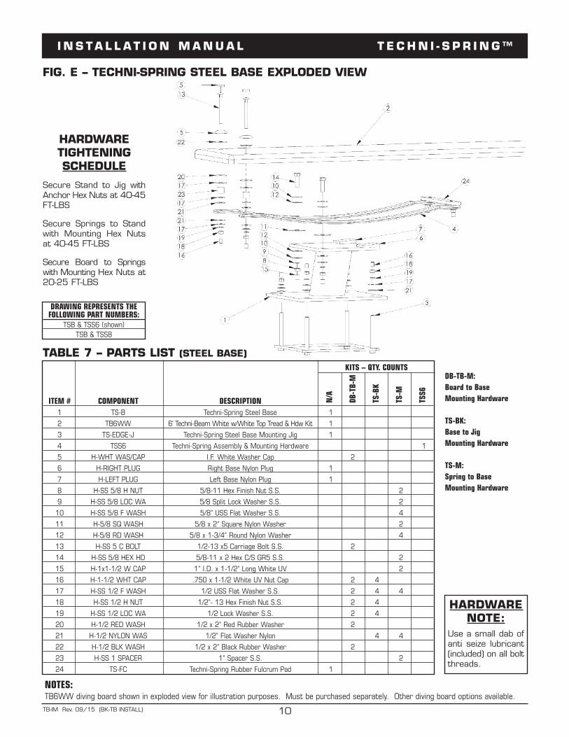
TABLE 7 – PARTS LIST (STEEL BASE)
FIG. E – TECHNI-SPRING STEEL BASE EXPLODED VIEW
DRAWING REPRESENTS THEFOLLOWING PART NUMBERS:
TSB & TSS6 (shown)TSB & TSS8
ITEM # COMPONENT DESCRIPTION N/A
DB-TB-
M
TS-B
K
TS-M
TSS6
KITS – QTY. COUNTS
1 TS-B Techni-Spring Steel Base 1
2 TB6WW 6' Techni-Beam White w/White Top Tread & Hdw Kit 1
3 TS-EDGE-J Techni-Spring Steel Base Mounting Jig 1
4 TSS6 Techni-Spring Assembly & Mounting Hardware 1
5 H-WHT WAS/CAP I.F. White Washer Cap 2
6 H-RIGHT PLUG Right Base Nylon Plug 1
7 H-LEFT PLUG Left Base Nylon Plug 1
8 H-SS 5/8 H NUT 5/8-11 Hex Finish Nut S.S. 2
9 H-SS 5/8 LOC WA 5/8 Split Lock Washer S.S. 2
10 H-SS 5/8 F WASH 5/8" USS Flat Washer S.S. 4
11 H-5/8 SQ WASH 5/8 x 2" Square Nylon Washer 2
12 H-5/8 RD WASH 5/8 x 1-3/4" Round Nylon Washer 4
13 H-SS 5 C BOLT 1/2-13 x5 Carriage Bolt S.S. 2
14 H-SS 5/8 HEX HD 5/8-11 x 2 Hex C/S GR5 S.S. 2
15 H-1x1-1/2 W CAP 1" I.D. x 1-1/2" Long White UV 2
16 H-1-1/2 WHT CAP .750 x 1-1/2 White UV Nut Cap 2 4
17 H-SS 1/2 F WASH 1/2 USS Flat Washer S.S. 2 4 4
18 H-SS 1/2 H NUT 1/2"- 13 Hex Finish Nut S.S. 2 4
19 H-SS 1/2 LOC WA 1/2 Lock Washer S.S. 2 4
20 H-1/2 RED WASH 1/2 x 2" Red Rubber Washer 2
21 H-1/2 NYLON WAS 1/2" Flat Washer Nylon 4 4
22 H-1/2 BLK WASH 1/2 x 2" Black Rubber Washer 2
23 H-SS 1 SPACER 1" Spacer S.S. 2
24 TS-FC Techni-Spring Rubber Fulcrum Pad 1
NOTES:TB6WW diving board shown in exploded view for illustration purposes. Must be purchased separately. Other diving board options available.
HARDWARENOTE:
Use a small dab ofanti seize lubricant(included) on all boltthreads.
HARDWARETIGHTENINGSCHEDULE
Secure Stand to Jig withAnchor Hex Nuts at 40-45FT-LBS
Secure Springs to Standwith Mounting Hex Nutsat 40-45 FT-LBS
Secure Board to Springswith Mounting Hex Nuts at20-25 FT-LBS
DB-TB-M: Board to BaseMounting Hardware
TS-BK: Base to JigMounting Hardware
TS-M: Spring to BaseMounting Hardware
I N S T A L L A T I O N M A N U A L T E C H N I - S P R I N G ™
11TB-IM Rev. 09/15 (BK-TB INSTALL)
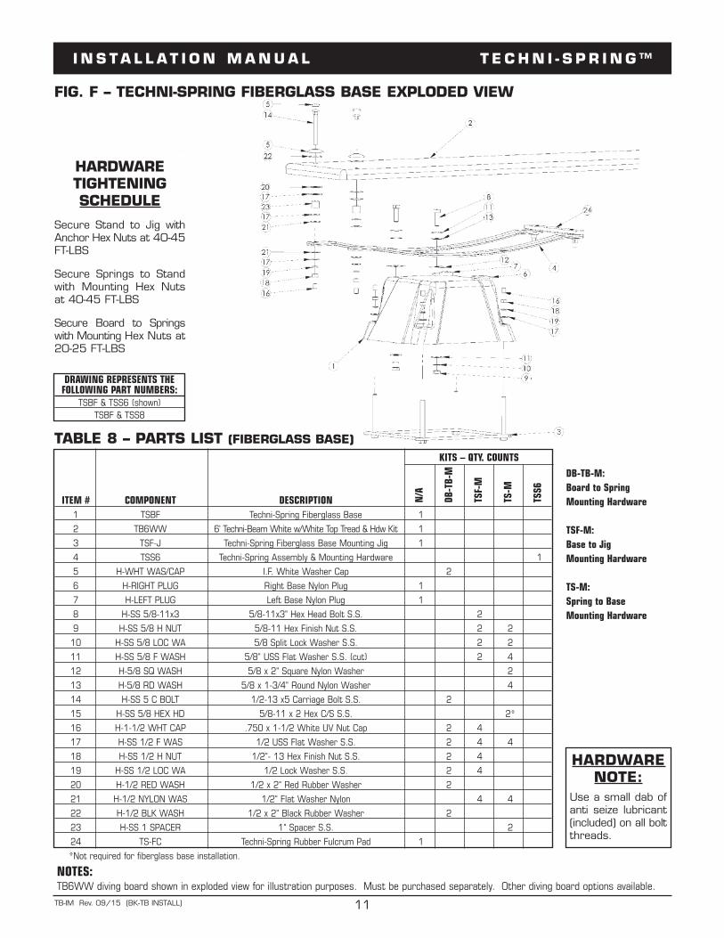
TABLE 8 – PARTS LIST (FIBERGLASS BASE)
FIG. F – TECHNI-SPRING FIBERGLASS BASE EXPLODED VIEW
DRAWING REPRESENTS THEFOLLOWING PART NUMBERS:
TSBF & TSS6 (shown)TSBF & TSS8
ITEM # COMPONENT DESCRIPTION N/A
DB-TB-
M
TSF-M
TS-M
TSS6
KITS – QTY. COUNTS
1 TSBF Techni-Spring Fiberglass Base 1
2 TB6WW 6' Techni-Beam White w/White Top Tread & Hdw Kit 1
3 TSF-J Techni-Spring Fiberglass Base Mounting Jig 1
4 TSS6 Techni-Spring Assembly & Mounting Hardware 1
5 H-WHT WAS/CAP I.F. White Washer Cap 2
6 H-RIGHT PLUG Right Base Nylon Plug 1
7 H-LEFT PLUG Left Base Nylon Plug 1
8 H-SS 5/8-11x3 5/8-11x3" Hex Head Bolt S.S. 2
9 H-SS 5/8 H NUT 5/8-11 Hex Finish Nut S.S. 2 2
10 H-SS 5/8 LOC WA 5/8 Split Lock Washer S.S. 2 2
11 H-SS 5/8 F WASH 5/8" USS Flat Washer S.S. (cut) 2 4
12 H-5/8 SQ WASH 5/8 x 2" Square Nylon Washer 2
13 H-5/8 RD WASH 5/8 x 1-3/4" Round Nylon Washer 4
14 H-SS 5 C BOLT 1/2-13 x5 Carriage Bolt S.S. 2
15 H-SS 5/8 HEX HD 5/8-11 x 2 Hex C/S S.S. 2*
16 H-1-1/2 WHT CAP .750 x 1-1/2 White UV Nut Cap 2 4
17 H-SS 1/2 F WAS 1/2 USS Flat Washer S.S. 2 4 4
18 H-SS 1/2 H NUT 1/2"- 13 Hex Finish Nut S.S. 2 4
19 H-SS 1/2 LOC WA 1/2 Lock Washer S.S. 2 4
20 H-1/2 RED WASH 1/2 x 2" Red Rubber Washer 2
21 H-1/2 NYLON WAS 1/2" Flat Washer Nylon 4 4
22 H-1/2 BLK WASH 1/2 x 2" Black Rubber Washer 2
23 H-SS 1 SPACER 1" Spacer S.S. 2
24 TS-FC Techni-Spring Rubber Fulcrum Pad 1
*Not required for fiberglass base installation.
NOTES:TB6WW diving board shown in exploded view for illustration purposes. Must be purchased separately. Other diving board options available.
HARDWARENOTE:
Use a small dab ofanti seize lubricant(included) on all boltthreads.
HARDWARETIGHTENINGSCHEDULE
Secure Stand to Jig withAnchor Hex Nuts at 40-45FT-LBS
Secure Springs to Standwith Mounting Hex Nutsat 40-45 FT-LBS
Secure Board to Springswith Mounting Hex Nuts at20-25 FT-LBS
DB-TB-M: Board to SpringMounting Hardware
TSF-M: Base to JigMounting Hardware
TS-M: Spring to BaseMounting Hardware
I N S T A L L A T I O N M A N U A L T E C H N I - S P R I N G ™
12TB-IM Rev. 09/15 (BK-TB INSTALL)
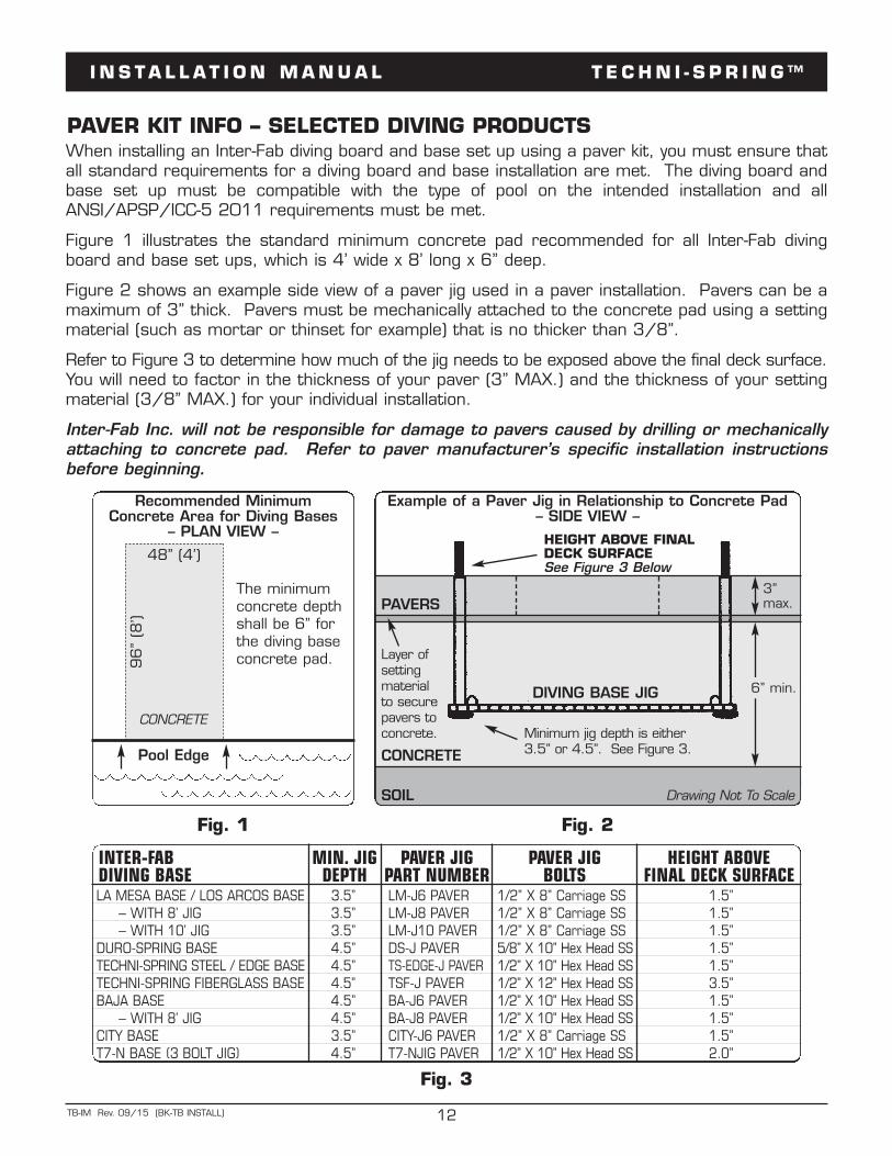
PAVER KIT INFO – SELECTED DIVING PRODUCTS
Fig. 1 Fig. 2
Pool Edge
Recommended Minimum Concrete Area for Diving Bases
– PLAN VIEW –
48” (4’)
96”
(8’)
The minimumconcrete depthshall be 6” forthe diving baseconcrete pad.
Example of a Paver Jig in Relationship to Concrete Pad – SIDE VIEW –
SOIL
CONCRETE
6” min.
Layer of setting material to securepavers toconcrete.
PAVERS3” max.
Drawing Not To Scale
HEIGHT ABOVE FINALDECK SURFACE See Figure 3 Below
CONCRETE
DIVING BASE JIG
Minimum jig depth is either3.5” or 4.5”. See Figure 3.
Fig. 3
INTER-FAB MIN. JIG PAVER JIG PAVER JIG HEIGHT ABOVE DIVING BASE DEPTH PART NUMBER BOLTS FINAL DECK SURFACELA MESA BASE / LOS ARCOS BASE 3.5” LM-J6 PAVER 1/2” X 8” Carriage SS 1.5”
– WITH 8’ JIG 3.5” LM-J8 PAVER 1/2” X 8” Carriage SS 1.5”– WITH 10’ JIG 3.5” LM-J10 PAVER 1/2” X 8” Carriage SS 1.5”
DURO-SPRING BASE 4.5” DS-J PAVER 5/8” X 10” Hex Head SS 1.5”TECHNI-SPRING STEEL / EDGE BASE 4.5” TS-EDGE-J PAVER 1/2” X 10” Hex Head SS 1.5”TECHNI-SPRING FIBERGLASS BASE 4.5” TSF-J PAVER 1/2” X 12” Hex Head SS 3.5”BAJA BASE 4.5” BA-J6 PAVER 1/2” X 10” Hex Head SS 1.5”
– WITH 8’ JIG 4.5” BA-J8 PAVER 1/2” X 10” Hex Head SS 1.5”CITY BASE 3.5” CITY-J6 PAVER 1/2” X 8” Carriage SS 1.5”T7-N BASE (3 BOLT JIG) 4.5” T7-NJIG PAVER 1/2” X 10” Hex Head SS 2.0”
When installing an Inter-Fab diving board and base set up using a paver kit, you must ensure thatall standard requirements for a diving board and base installation are met. The diving board andbase set up must be compatible with the type of pool on the intended installation and allANSI/APSP/ICC-5 2011 requirements must be met.
Figure 1 illustrates the standard minimum concrete pad recommended for all Inter-Fab divingboard and base set ups, which is 4’ wide x 8’ long x 6” deep.
Figure 2 shows an example side view of a paver jig used in a paver installation. Pavers can be amaximum of 3” thick. Pavers must be mechanically attached to the concrete pad using a settingmaterial (such as mortar or thinset for example) that is no thicker than 3/8”.
Refer to Figure 3 to determine how much of the jig needs to be exposed above the final deck surface.You will need to factor in the thickness of your paver (3” MAX.) and the thickness of your settingmaterial (3/8” MAX.) for your individual installation.
Inter-Fab Inc. will not be responsible for damage to pavers caused by drilling or mechanicallyattaching to concrete pad. Refer to paver manufacturer’s specific installation instructionsbefore beginning.
I N S T A L L A T I O N M A N U A L T E C H N I - S P R I N G ™
13TB-IM Rev. 09/15 (BK-TB INSTALL)
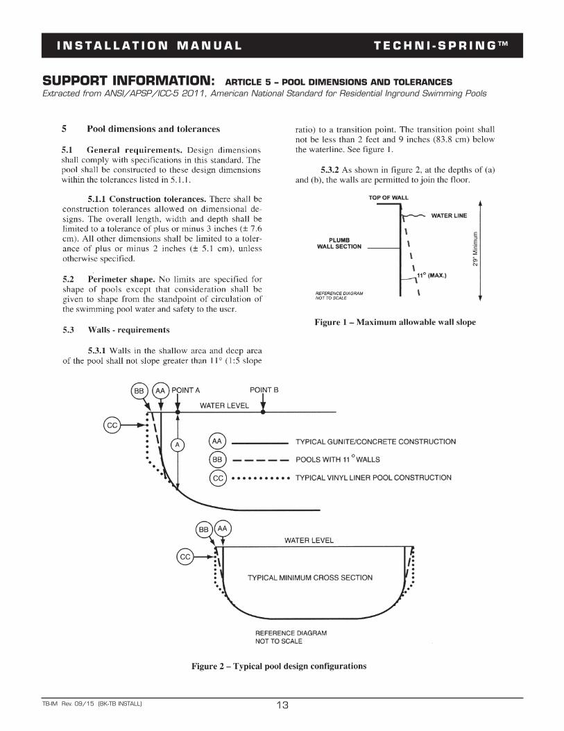
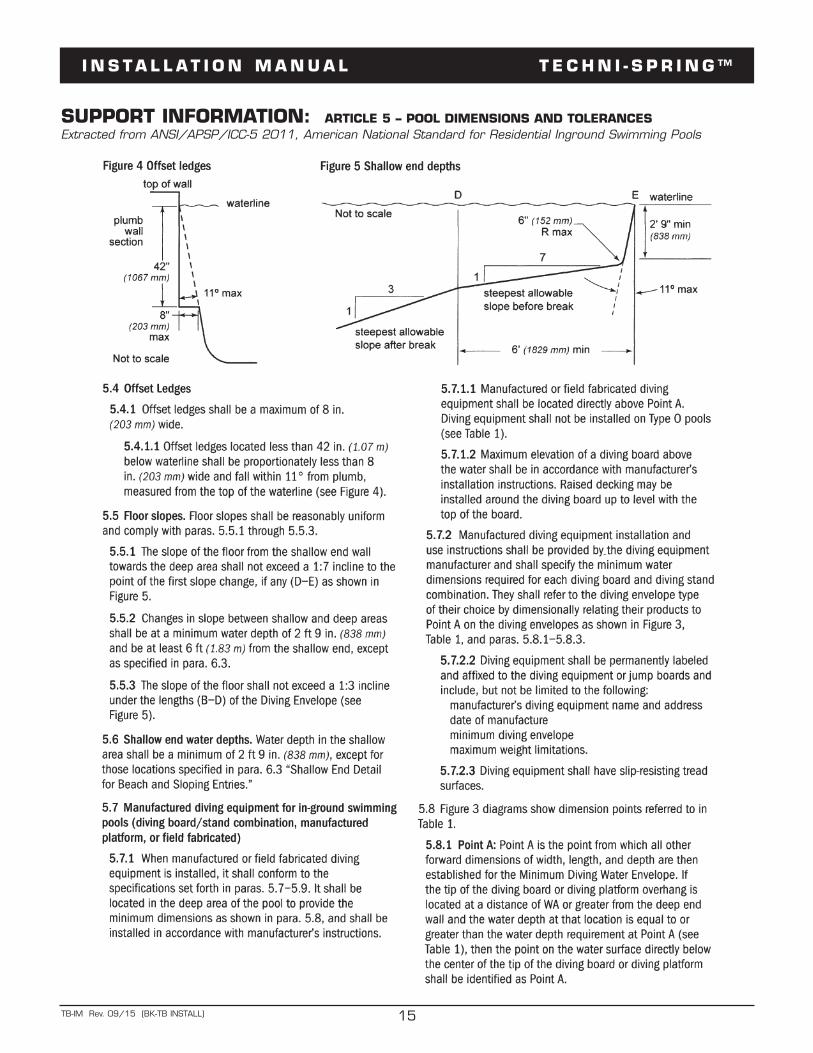
SUPPORT INFORMATION: ARTICLE 5 – POOL DIMENSIONS AND TOLERANCES Extracted from ANSI/APSP/ICC-5 2011, American National Standard for Residential Inground Swimming Pools
I N S T A L L A T I O N M A N U A L T E C H N I - S P R I N G ™
14TB-IM Rev. 09/15 (BK-TB INSTALL)
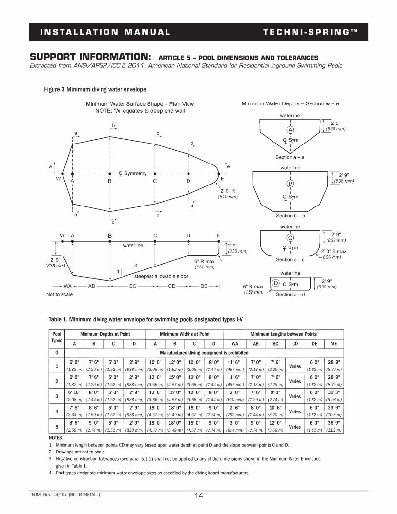
SUPPORT INFORMATION: ARTICLE 5 – POOL DIMENSIONS AND TOLERANCES Extracted from ANSI/APSP/ICC-5 2011, American National Standard for Residential Inground Swimming Pools
I N S T A L L A T I O N M A N U A L T E C H N I - S P R I N G ™
15TB-IM Rev. 09/15 (BK-TB INSTALL)
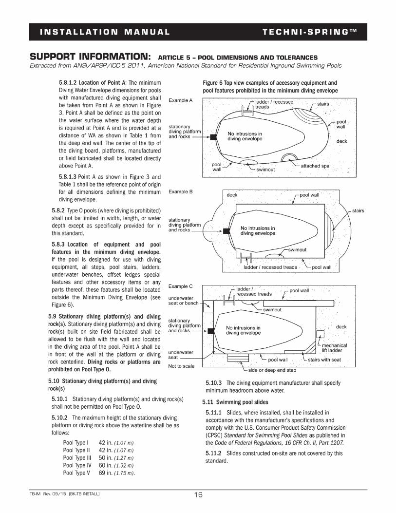
SUPPORT INFORMATION: ARTICLE 5 – POOL DIMENSIONS AND TOLERANCES Extracted from ANSI/APSP/ICC-5 2011, American National Standard for Residential Inground Swimming Pools
I N S T A L L A T I O N M A N U A L T E C H N I - S P R I N G ™
16TB-IM Rev. 09/15 (BK-TB INSTALL)
SUPPORT INFORMATION: ARTICLE 5 – POOL DIMENSIONS AND TOLERANCES Extracted from ANSI/APSP/ICC-5 2011, American National Standard for Residential Inground Swimming Pools
I N S T A L L A T I O N M A N U A L T E C H N I - S P R I N G ™
17TB-IM Rev. 09/15 (BK-TB INSTALL)
NOTES:
I N S T A L L A T I O N M A N U A L T E C H N I - S P R I N G ™
18TB-IM Rev. 09/15 (BK-TB INSTALL)
3050 S. Alvernon Way • Tucson, AZ 85713520.790.7040 • 800.737.5386 • Fax 520.790.7127 • inter-fab.com
LIMITED WARRANTYInter-Fab, Inc. will repair or replace, at its option, any product manufactured by Inter-Fab, Inc. that fails duringthe applicable warranty period because of a manufacturing or material defect; provided that the defect is notthe result of improper installation, improper use or care, negligence, alterations or modifications to the product,or natural accidents (acts of God). The applicable warranty period for products manufactured by Inter-Fab,Inc. is three (3) years from the date of retail purchase, except as specified below:Echoes of Nature™ products are individually handcrafted and painted by skilled artisans and as a result,dimensional differences and color variations are normal and are not a basis for warranty coverage. The warrantyperiod for pumps sold with the Echoes of Nature™ products is three (3) years from the date of retail purchase.Water Sports™ sports equipment warranty periods are as follows: Volleyball Poles, Basketball Poles,Basketball Rim, and Basketball Backboard are one (1) year from date of retail purchase. Volleyball, VolleyballNet, Basketball, Basketball Net, and pumps are warranted for ninety (90) days from date of retail purchase.The Board Fall, Board Fall-L (LED), and Board Fall-F (fiber optic) water features, used for the Jump & Splash™,T7™ and aquaBoard™ products, have a warranty period of one (1) year from the date of retail purchase.Zoomerang™ slide products warranty period is one (1) year from the date of retail purchase.Build Your Own Slide™ (BYOS™), Build Your Own Slide 2™ (BYOS 2™), Garden Ride Series™, Pool/Spa Table™,Pool/Spa Seat™, and Pool Lifestyle™ products warranty periods are one (1) year from the date of retail purchase.City 2™ Slide and City Base™ products warranty period are one (1) year from the date of retail purchase.i-Lift™ products warranty period are two (2) years from the date of original shipment. The battery, charger,receiver (control box on i-Lift), transmitter (remote), and actuator have a warranty period of one (1) yearfrom the date of original shipment.Unless expressly stated otherwise all products manufactured by Inter-Fab are for residential installation (singlefamily residence) inground pool use only. Inter-Fab, Inc. expressly disclaims any and all warranties and liabilityarising from the installation or use of its residential products for any non-residential use such as semi-public,public, or commercial applications. Products expressly manufactured for commercial installation and use will besubject to this limited warranty.This limited warranty is in lieu of all other warranties, whether express or implied. Inter-Fab, Inc. disclaimsany warranty of merchantability or fitness for a particular use, and noninfringement in relation to any of its productsand Inter-Fab, Inc. is not liable for consequential, incidental or specific damages. This warranty is limited tothe repair or replacement of the manufacturing or material defect, or refund of the original purchase price,whichever is less, at the sole option of Inter-Fab, Inc., and expressly does not cover any labor or reinstallationexpenses related to the replacement of any and all Inter-Fab products. This limited warranty shall be the soleand exclusive remedy of irrespective of whether the claims are made in contract, tort, warranty, law, equityor by statue.This warranty is to the original purchaser of the product only. Inter-Fab’s limited warranty is neither transferablenor portable from consumer to consumer. The effective coverage date begins at the date of retail purchase.Product owner or representative must notify Inter-Fab, Inc. (or its wholesale agent) in writing, giving a fulldescription of the nature of the product defect or failure along with proof of purchase, serial number(s) of theproduct and photos within thirty (30) days of the expiration of the applicable warranty period. Inter-Fab, Inc.reserves the right to physically inspect damaged or defective products or components to determine the causeof the damage or defect, prior to authorizing repair or replacement of its products.