Embed Size (px)
Citation preview
FILE COpy NO.I-W CA
TECHNI CAL !LEIWRANDUMS
F .IL£ Y
RATIOlTAL ADVISORY CmQ.:ITTEE FOR AERo:r~AUTICS
No. 531
'.IIlELDING RUSTPROOF STEELS
By W. Hoffmann
From Autogene Meta11bearbeitung December 15, 1927 (Vol. 20)
Washington September, 1929
, '
----------~----------~------~--~--------~------------------~--- -
NATIONAL ADVI SORY C0r.1:HTTE!C FOR AERONAUTI CS .
TECENI CAL lilE110RANDUH TO . 531 .
1iJE LDING RUSTPROOF STEELS . *
By W. Hoffmann .
Since the dis covery of r ustproof staels and the l~ecogni tion
of their advantag~) their f ield of application has steadily in-
cr eased , especially where undesired chemical attacks on metals
and metal alloys take place . Their use is increasing with the
improvements in the process of welding them .
The most used rustproof steels are high-percentage chrome
and chrome-nickel steels . A special advantage of chrome steel ,
aside from its resistivity to corrosion., is its sui tabi1i ty fo r
structural purposes , because of its superior Taechanical proper-
ties fu~d its strength even at high temperatures .
The following experimental results will perhaps increase
the knowledge of the process of welding rustproof steels . The
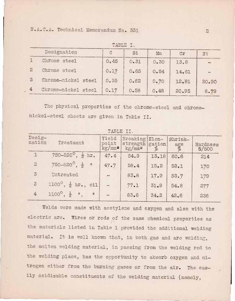
experiments were made with two chrome-steel sheets and with two
chrome- steel- nickel sheets having the composition shown i n
Table 1.
'" I1 Ueber das Schwe issen von rosts i cheren St~hlen , II a paper r ead September 4 , 1927 R at the annual meet ing of the German Acetylene Society in Dus seldorf . Fr om Autogene Metallbearbeitung, De c ember 15 , 1927 (Vol. 20), pp . 337- 343 .
\
N. A. C. A. Teclmi cal Memorandum No . 531
TABLE I.
Designati on I 0 L.Si 1 Chr ome steel 0045 I 0 . 31
2 Chrome steel 0 . 17 0 . 65
3 Chrome-n i ckel steel 0. 35 I
0 . 62
4 Chrome- n i ckel steel I 0 . 17 I 0 . 58
Mn
0 . 30
0 . 54
O. ?O
I i 0 . 48
Or
13!8
14. 61
l2~8l
20 . 95
2
Ni
20 . 90
6 .79
The physical proper ties of the chrome- steel and chr ome-
ni ckel - steel shee ts ar e given in Table II .
------Des i gnation
1
3
Treatment
.750- 820° , t hr .
.7 50-820° , i II
Untreat ed 3
3
4
1100° , t hr . , oil
II If
----
TABLE II.
Yi eld poi nt kg/mm til
47 . 4
47 . 7
Breaki ng strength
kg/ mm 2
58 .4
83 . 8
77.1
83 . 6
Elongat ion
fa ·
I 13.18
I 15 . 2
17 . 9
31 . 9
34. 2
Shrink-a~e
60 .6
52 .1
53.7
54. 8
42 . 6
Ha:rdne ss 5/500
214
170
179
277
238
Welds vre r'e made with acetyl ene and oxygen and also with the
electr i c a r c . Wires or rods of the same chemical propertie s a s
the materials listed i n Table 1 provided the addit ional welding
mQterial. It is wel l known that , in both gas and arc weldi~b'
the molten wel d i ng materi al, in passi ng f r om the welding rod to
the welding pl ace , has the opportuni ty to absor b oxygen and ni-
trogen either f r om the burni ng gases or f rom the air . The eas-
ily oxidizable const ituents of the welding mater i al (namely,
N. A. O. A. Technic al Memo r andlX11 No . 531 3
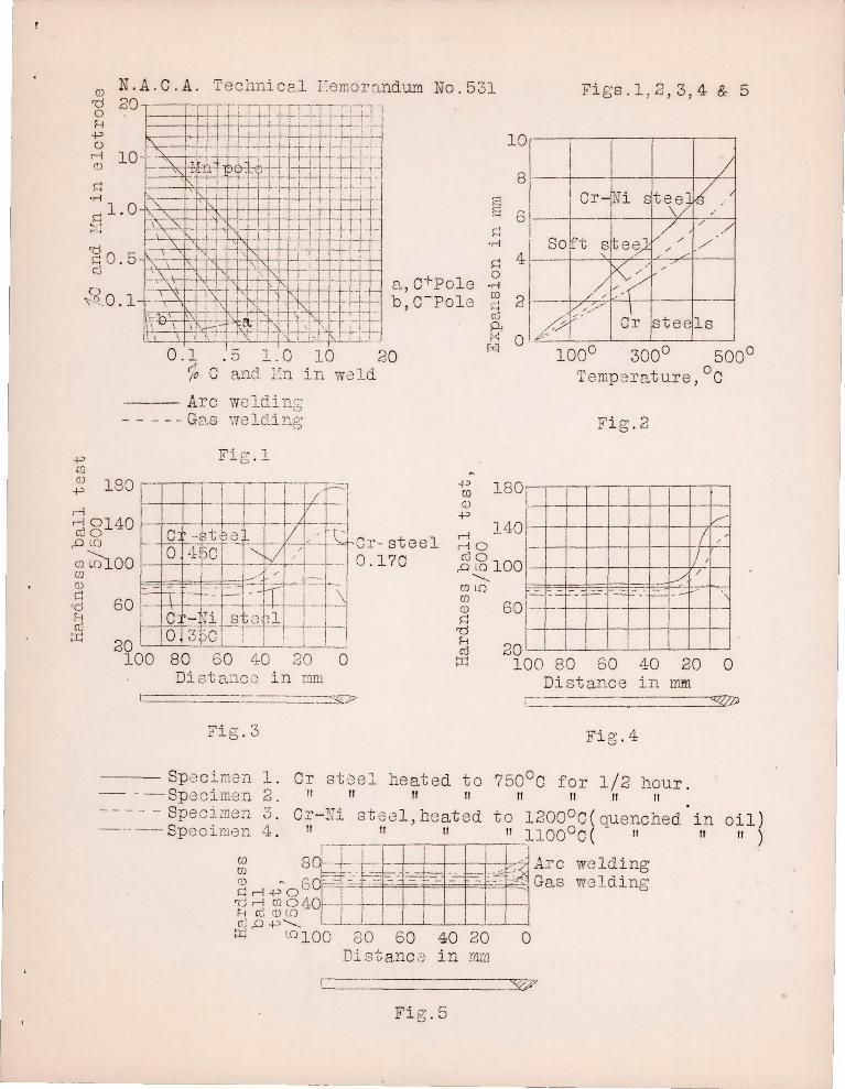
carbon, silicon, and manganese ) are thus r educed, as shown in
Figur e 1. The great loss of t hese element s i n gas welding l es-
sens the st r ength of the materi al. I n the arc process the ab-
sorpti o~ of oxygen and nitrogen is small , while the s tr ength
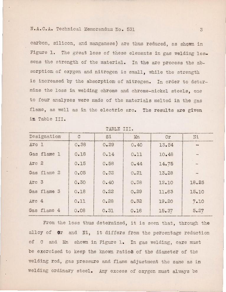
i s inc r eased by the absorptiom of nitrogen. In or der to deter-
mine the loss i n welding chrome and chrome - nickel steels , one
t ,o four analyse s were made of the mat er i al s melt ed in the gas
f l ame , as wel l as in the electric a..r c . The results are given
in Table III.
TABLE III.
DesignatioIT' 0 Si Mn Or Ui
Arc 1 0 . 38 0 . 29 0 . 40 13 . 54 -Gas flame 1 0 . 18 0 . 14 0 . 11 10 . 48 -
Arc 2 0 . 15 0 . 58 I 0 . 44 14. 75 -
Ga s fl ame 2 0 . 05 I 0 . 32 0 . 21 13 . 28 -
Arc 3 I 0 . 30 I 0 . 40 0 . 38 1 2 . 10 18.25 I
Gas flame 3 I
0 .18 0 . 22 0 . 29 11.63 15.10
Arc 4 0 . 11
I 0 . 28 0 . 32 19 . 20 7.10
Gas fl ame 4 i
0 . 08 0 . 31 0 . 16 15.37 5.27 I !
From the loss thus dete r mined , it is s een that , through the
al loy of ,r and Ni , it differs from the per centage r eduction
of 0 and Mn shown in Figure 1 . I n gas wel ding, car e must
be exercised to keep the known ratio~ of the diameter of the
welding rod, gas pressure and flan18 adjustment the same as in
weldi ng ordinary steel . Any excess of oxygen must al".vay s be
N. A . 8 . A. Technici1l Memorandum 10 . 531 4
avoided , since otherwise there WOl.11d be too great a lo ss of Ni
and especially of Or. Any excess of acetylene must be avoided,
s ince this would result in a har mful absorptiorr of carboll by the
met ale I n the gas-wel ding . exper iEJ.ent s , it was found that . the
weld I,Tas not so deep as wi th ordinary s te el, so that even thin
shee ts had to be we l ded on both sides .
Attempts to weld the chrome and chr ome- nickel rods by the
el e ct ric arc shovl8d a great los s in the added component s , especi
ally in chromi wa . Aft er the chr ome ~!d chr ome- ni ckel rods were
provided with a protecting covering during the welding in the
electr i c arc , this loss was reduced. By adding the reduced con
stituents i n the fo rm of powder to the prot ect ing material, the
ori g inal excellence was approximat ely attained. A better way to
avoid the r educt ion is to add corre spondingly larger propor tions
of the alloys to the welding r ods .
I n welding clean chrome and chr ome- ni ckel rods in the arc ,
the melt ing took pl ace very qui ckly, even with a weak welding
cur r ent, so that the depth of the weld was very small with the
use of e i ther the positive or negat ive pole. This too-rapid
melting can be avoided by the covering . The protecting substance
mus t melt eas ily and spr ead quickly over the surf ace , since the
hardening occur s quickly. ThUS, inclusions of the protecting
material ar e avoi ded . Such inclusions must be avo ided, because
they woul d unfavorably affect the phys i oal properties and the
resistivity to corrosion.
N. A.C . A. Technic al Memor andum No . 531 5
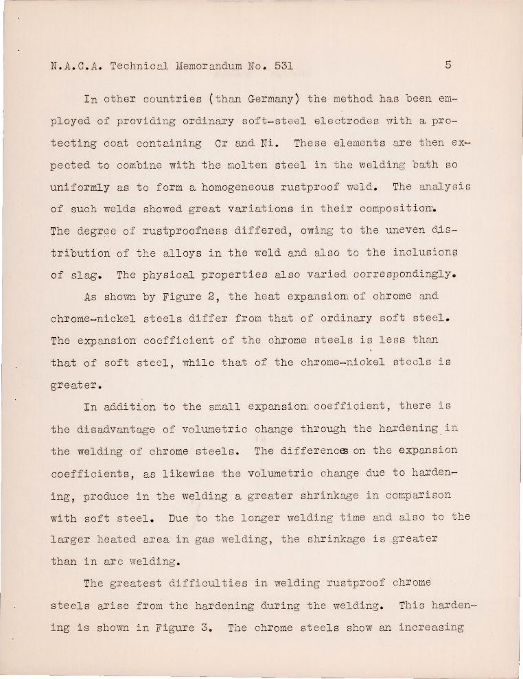
I n other count ries ( than Germany) the method has been em
ployed of provi di ng ordi nary soft-st eel el ect r odes with a pr o
tecting coat containing Cr and Ni. These el ement s ar e then ex
pected to combine with t he molt en st ee l i n the wel d i ng bath so
uniformly as to fo rm a homogeneous rustpr oof weld. The analysis
of suc h welds showed gre at vari ations in their compo s itioIT~
The degr \3e of rustpr oofne ss differed, owing to the uneven d.is
tribution of the all oys in the v-Jeld and also to the i nc l usion!?
of slag. The physi cal proper t ies also varied cOl'respondi ngly.
As shovffi by Figul'e 2, the heat expansi om of chr ome and
chrome- nickel steel s di ffe r from that of or di nary soft steel.
The expansi on coefficient of the chrome steel s i s l ess than
that of soft steel, whi l e that of the chrome- nickel stcel s is
great er .
I n additi on to the small expansion. coeffici ent, there is
the disadvantage of volumetri c change through the hardeni ng . i n
the welding of chrome steels. The differencffi on t he expansion
coefficients, as likewise the volumetric ch~~ge due to harden
ing , produce in the welding a greater shrinkage i n comparison
with soft steel . Due to the longer welding time ~ld also to the
larger heated a.rea i n gas welding, the shr inkage is greater
than in ar c vve l di ng .
The greatest difficult i es i n we l ding rustproof chrome
steels arise from the har dening during the weldi ng . This harden
ing is shown in Figur e 3 . The chrome steels show an i ncreas i ng
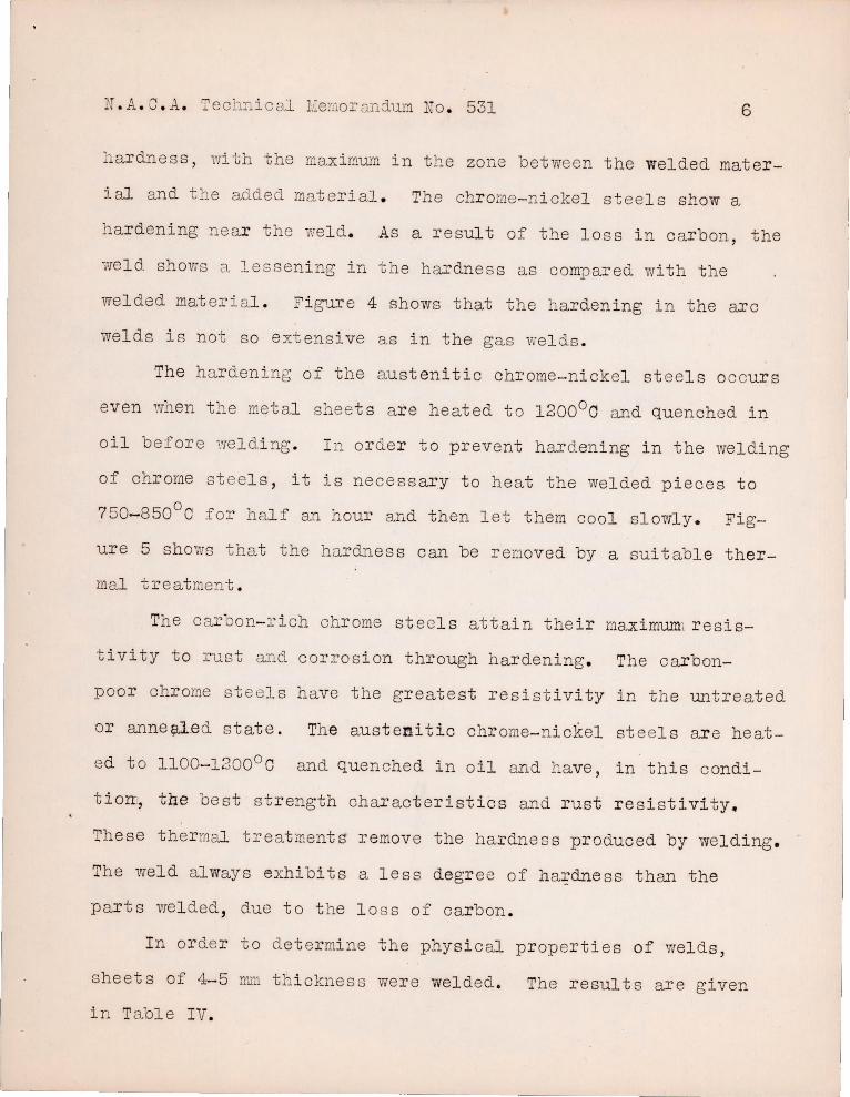
N . A. C . A. Technical l!=emoI'Cw dum No . 531 6
hardness , rvi th the n:aximum in t lo.e zone be t ween the welded mater
ial and the added material . The chrome- n ickel steels show a
hardening ne ar t he wel d . As a r esult of t he lo s s in c arbon, the
';;:reld shows C\, lessening in the hardne ss as compared with the
welded mat erial . Figure 4 shows that the hardening in the arc
welds is not so extensive a s in the gas wel ds .
The hardening of the austenitic ohI'ome-nickel st eels occurs
even 1.vhen t he metal sheets are heated t o 1200°0 and quenched in
oil before 1.'reldi ng . I L or der to prevent hardening in the weldi ng
of chrome steel s , it is necessary to h eat the welded pieces to
7 50-8500 0 for half an hour and then l et them cool slowly. Fig
ure 5 shows that the hardnes s can be renoved by a suitable ther
mal treatment .
The car on- r i ch chrome steels attain the ir maximum, r esis
t ivity to rust and corrosion through hardening . The carbon-
poor chr ome steels have the greatest resis t ivity in t h e untreated
or anne ~ed state . The austenitic chr ome- nickel st eels are heat
ed to 1100-1200 0 0 and quen ched i n oil and have, in this condi
t iom, t4e bes t st r ength charact eristics and rust resi st ivity.
These thermal treatments remove the hardne s s produced by welding .
The weld always exhibits a less degre e of h ardness than the
parts wel ded , due to t he lo s s of car bon .
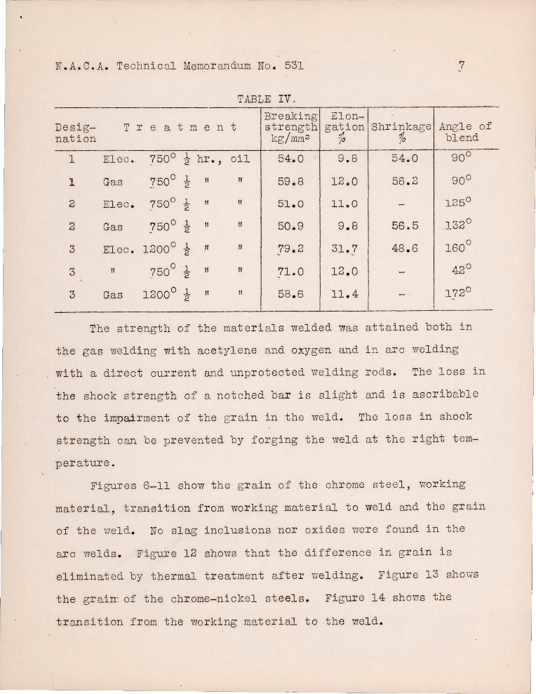
In orde r to det er mine the physical p r operties of wel ds ,
sheet s of 4-5 nun t h i ckness we r e welded . The results are g iven
i n Table IV.
N. A. C. A. Technical Memorandum No. 531 7
TABLE IV. Breaking Elon- -
Desig- T r e a t m e n t strength gat ion Shrinkage Angle of nation kg/ mm 2 ..1 .% blend -io
I
1 Elec. 7500 .1. hr., oil 54.0 9 . 8 54 . 0 90 0 - 2
1 Gas 750 0 1 " " 59.8 12.0 56.2 900 '2
2 Elec . 7500 t " " 51 . 0 11.0 - 1250
2 Gas 750 0 1 II If 50. 9 9 . 8 56.5 .1320 - '2
3 El ec . 12000 1 " " 79.2 31.7 48 . 6 1600
'2 -3 If 750
0 1 If 11 71.0 12 . 0 42 0 '2 -.
3 Gas 12000 1 " " 58 . 6 11 . 4 I 1720
'2 - . -
The strength of the materi als welded was attained both in
the gas welding with acetyl ene and oxygen and i n arc welding
with a direct ourrent and unprotected welding ro ds. The loss i n
the shock st rength of a notched bar is slight and is ascribable
to the impairment of the gr a in in t he weld. The loss in shock
strength can be prevented by forging the weld at tho right tem-
per ature.
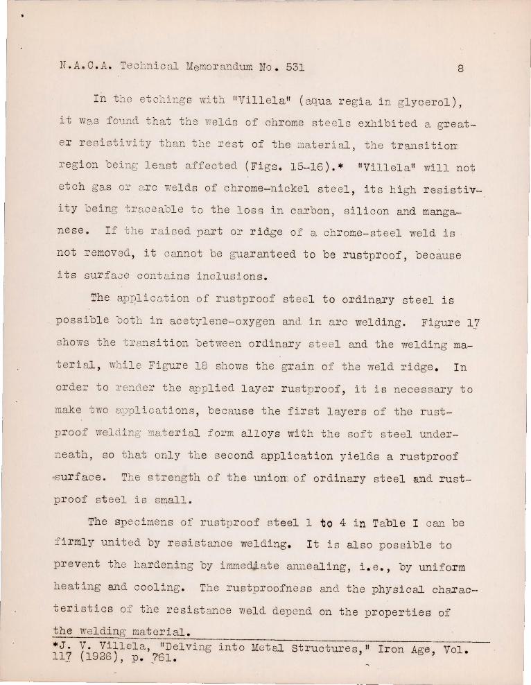
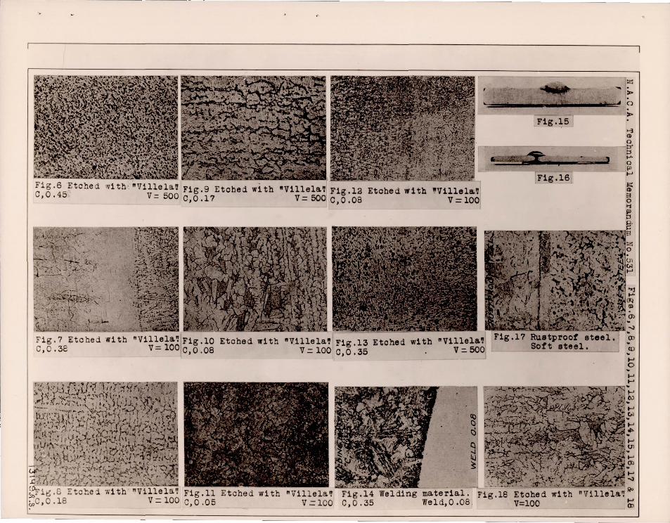
Figures 6- 11 show t he gr a in of t ho chrome steel, wo rking
material, t ranBition f r om working materi al to weld and the grain
of the wel d . No slag inclusions nor oxides wer e found in the
arc welds. Figure 12 shows that the difference in gr ain i s
eliminat ed by thermal treatment after v/elding. Figure 13 shOl-m
the gr a irr of the chrome- nickel steels. Figure 14 shows the
t r ansi tion from the wo rking material to the weld .
N. A.C . A. T l~chn i c3.1 Memo r andl.lm No . 531 8
I n t~c etc:1ings with "Vill ela" ( aqua r egi a i n glycerol ) ,
it Wa,s f ound that the wel ds of chrome ste el s exh i bi ted a gre a t -
e r r es i stivity than t~1e rest of the ;'i1aterial , the transi tion-
region be i n§.: le ast affected (Figs . 15-16) . " "Vill el a " will not
et ch gas o~ a rc welds of chrome- n i ckel steel , it s h i gh re s istiv-
i ty oe ing tI'C"l.C8aole to the l oss in carbon, sili con and manga-
nese . I f the r a i sed part or ridg e of a ch:rome-steel weld is
not removed , it cannot be guaranteed to be r u stp roof, because
its surface contains inclusions .
The applica tion of rustproof st e el t o or din ary steel is
possible ooth in acetylene-oxygen and in a r c welding . Figure 17
shows the t 1' 8..:.'1 s i tion between ordinary st ee l and t h e welding ma-
teri al , whi l e Figure 18 shows t he gr a in of the wel d ridge . In
order to rende r the appli ed l ayer rus t p ro of , it is nece ssary to
make two c:~)'plic ations , because the first l ayers of the r ust -
p r oof weld i n,; ~at er i oJ. fo :cm alloys with the soft steel under-
neath, s o that only the s e c ond applic at ion yields a rustproof
su rfac e. The st rength of the unioIT of ordinary steel and rust-
p roof s t eel is small.
The spe c i mers of rustp r oof s t eel 1 to 4 in Table I can be
f irml y united by r es ist ance welding . I t is also possible to
p revent the har deEing by irnme diate anneal ing, i . e . , by unifor m
heating ~~d c ooling . The rustproofness and t he physical charac
teristics of the resist a...YJ.ce weld depend on the propert i es of
the welding mat er ial . --------------------------------------------------------*J . V. Villel a , "Delving int 0 Met al s t ructure s , " I r on Age , Vol . 117 (1926 ), p . 761 .
N.A.C . A. Technic al Memor andum Nt;:l. 531 9
S umma r y
1. Rus tproof s t eel s can be easily wel ded by the acetyl ene-
oxygen process .
2. The welding r ods must be protected i n ar c welding .
3 . The har dness resulting from tbe weldi ng process must be
removed by the r mal t r eatment.
4 . The physical char acteri s tics of rus tproof-steel welds
are better than those of soft-st eel welds .
5. Owing to it s lo ss in carbon, sili con ru1d mangane s e, the
steel mel ted in the gas fl rune or electric arc i s more rus tpI'oof
after than befor e welding .
Bib 1 i 0 g ra p h y
Daeves,
St rauss ar..d Maur~r,
Rappatz,
Ait chi son, Leslie
Hof fmann ,
Stahl und Ei s en , 1924, No . 24.
Kr uppsche s I~onat sheft, Aug ., 1920 .
"Die Edelst~l e, " 1925, published by Jul ius Springer .
"Rustproof Ste el ," Ir on Oool Tr. Rev., Oct . 28 , 1921.
"Chrome Ir ons and Ohrome St e els,1I Eng i neeri ng , Dec . 2 , 1921 , p . 7.?1.
Diskus s ionsbericht No . 12 der Techn . Hoch schule, Zuri ch , June , 1926 .
Tr ansl at ion by Dwi ght U. Miner, Nationa.l Advisory Cornmi tt ee f or Ae ronautics .
-P m Q) .p
Q)
'd o H
-P o rl
'--- Arc woldi.l1[; - - - - _. G2.S welding
Fi g .l
60 40 20 0 Di s ta.:1c 0 in mm
Fig.3
NO.531
lO'-~I-'---'---'-----'
8--·~1 ---+---+---+-r-
.~ 6 I~~:r_:--l--__ I---¥---+-;~-t ~ 4 ~-f---->.;i--r'-+"-;,..,,-----1 o
/ 8. ,O+Polo '''; W b , O-Po l e ,-' @ Pi ~~
j ~-"';/ 2 r--·-~h-; -' o "'{~/7f . .... Or s t ee l s
r-if
~ 180 G.)
-P
r-l 140 r-l0
E~ lOO ............
WID
g-; 60 ~ 'd H (lj 20
! I ,. ,._.
~-
I-[
1 00° 300 ° 500°
I I
i-- .
.-I-
I
° Temp~rature ) 0
Fi g . 2
V-
If ~-1--: /
-~ - r-' -:: - -I--- --
i !
~ 1 00 80 60 40 20 o Di stan.ce in mm
; _____ . ____ '<0:/.2..;:"
Fi g . 4
----- Specimen 1 . Or steel heated to 7500 0 for 1/2 hour. - - -Specimen 2. II" " " " " " II
- - - - - Spec j.men 3. Or- ::Ji stee l , heated to 1200°0 ( quenched - ---- Specimen 4 . II II II If 110000 ( If
1"--;--- ! ! ' !
W 8a- + t--. L , .~';.( Arc weld i ng ;g ~ '-:' 0Bof::.et·~~ C-F. ',"~ Gas welding ~ r-I-P 01.- -r-- - I '"d rl CJJ 0 40 .--+. -+-+-/+--+--+--+--~~ cC Q) LO i I cr; ,D +"............ ._._._..i----l_'-_-'--.!.-. .!.-. ..1...--'
::rl LO 100 80 60 40 20 0 Di 87; a.no,'; i n Yfllll
r----' 3:527"
Fi g . 5
i n oil) II II)
r -
Fig. S Etche d w1th . "Villela~ Fig.9 Etohed .ith ·Villela' Flg.12 Etohed with .Villel&' C,0. 45 V= 500 e,0.17 V= SOO C,O.OB V=100
"Villela' Flg.13 Etohed with V = 100 C, 0 . 35 .
z ... .
Fig.15
-F1g.16
F1g.1? Rustproof ateel. Soft steel.
> ()
>
~ <II 0 ~ ::1 ..... 0 III ~
15:: CD 3 0 '1
~
CD
..... o
Etche d wi th "Villela'! Fig .14 V = 100 C, 0 .35
material. Fig.18 Etohed with "Villel&~~ Weld,O.OB . V=lOO ~