Embed Size (px)
Citation preview
1
IS250 IS250C
REPLACEMENT OF FUEL PRESSURE SENSOR GASKET
1. OPERATION FLOW CHART --------------------------------- 3 2. IDENTIFICATION OF AFFECTED VEHICLES ---------- 4 3. PREPARATION -------------------------------------------------- 5 4. WORK PROCEDURE ------------------------------------------- 7
TECHNICAL INSTRUCTIONS
2
Safety Precautions
Be sure to observe the following precautions to prevent accidents and injuries.
- Park the vehicle and chock the wheels.
- If it is necessary to start the engine, perform the operation in a well ventilated area.
- Before removing and reinstalling heavy parts such as the engine, transmission and differential using specified tools, check that there are no problems with the tools.
- When working in a group of 2 or more, each person must work to ensure the safety of all team
members.
- To prevent burns and other injuries, use extra caution when handling parts that are subject to high temperatures, as well as rotating, sliding, or vibrating parts.
- When lifting the vehicle using a jack, support it in the specified location using a safety stand.
- When lifting the vehicle using a lift, lock the lift for safety.
Also perform the following operation with care.
Use of auto lift - Make absolutely certain that there are no other workers and no tools, parts, or other objects
within the movable range of the lift. Also, be sure to announce all lift operations out loud (such as “Raising the lift!” and “Lowering the lift!”) to alert other workers.
- When raising or lowering the lift, pay attention to the positions of your arms, legs, and other
body parts, and be extremely careful to prevent them from being caught in the lift.
Use of brake cleaner - Use brake cleaner for appropriate purposes in accordance with instructions in the manual.
- Do not use brake cleaner to remove dirt or stains from the engineer clothes and so forth, as it
can catch on fire and cause serious burns. < Precautions >
- Do not use brake cleaner near flames or fire.
- Do not use large amounts of brake cleaner in a room where a fire is burning.
- Do not keep brake cleaner in a place subject to high temperatures exceeding 40°C, such as a place subject to direct sunlight or near fire.
- Do not put brake cleaner in fire.
Edges - When handling the edges of parts and panels, wear protective gloves or apply protective tape to
the edges to prevent injuries to your hands and fingers.

3
1. OPERATION FLOW CHART
No
Yes
Check whether or not the vehicle has an affected VIN.
No further action is required.
Return the vehicle to its original state and finish the work.
Remove the vehicle components. Proceed to section E on page 19.
Remove the fuel pressure sensor. Proceed to step 17 on page 30.
Reinstall the fuel pressure sensor and the vehicle components. Proceed to section F on page 35.
4
2. IDENTIFICATION OF AFFECTED VEHICLES
2.1. COVERED VIN RANGE
Model Name VIN Range
WMI VDS VIS
IS250
JTH BF5C2* *2094264~*2100116
JTH BF5C2* *5107249~*5128000
JTH BK262* *2000015~*2100283
JTH BK262* *5000033~*5127450
JTH CF5C2* *2032533~*2034458
JTH CF5C2* *5036007~*5044084
JTH CK262* *2000002~*2032532
JTH CK262* *5000017~*5036006
IS250C JTH FF2C2* *2500062~*2513985
JTH FK252* *2500065~*2513982
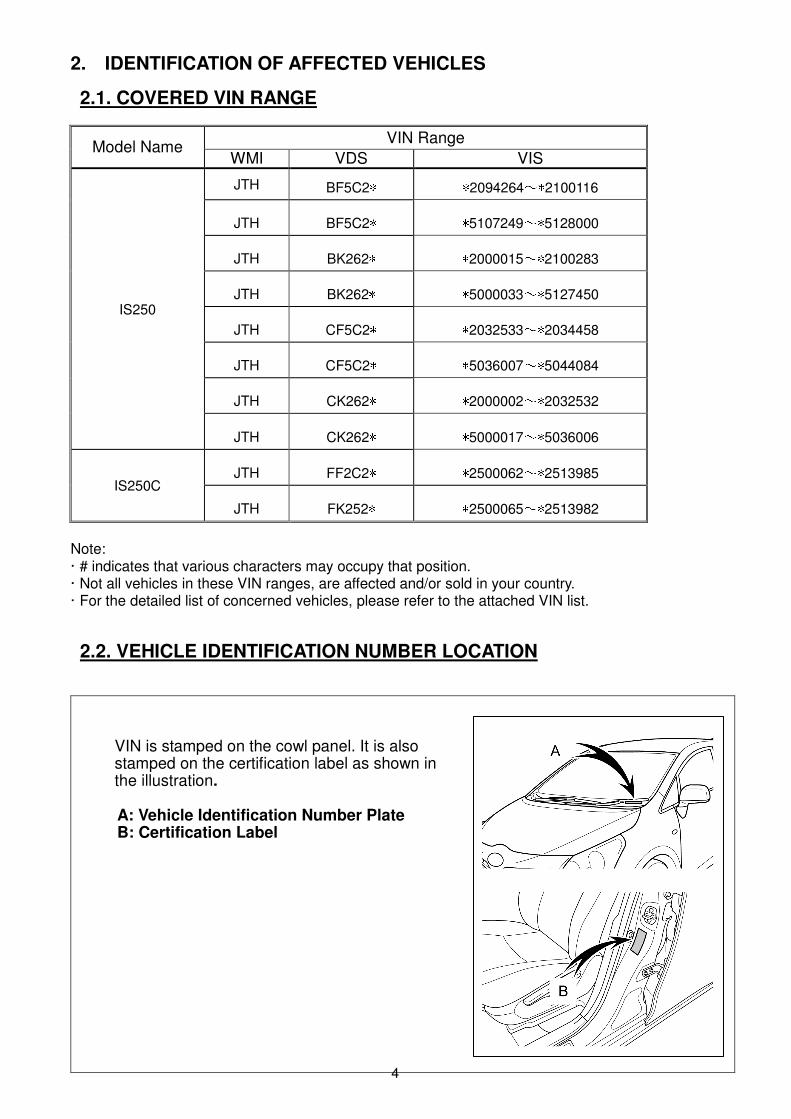
Note: · # indicates that various characters may occupy that position. · Not all vehicles in these VIN ranges, are affected and/or sold in your country. · For the detailed list of concerned vehicles, please refer to the attached VIN list. 2.2. VEHICLE IDENTIFICATION NUMBER LOCATION
VIN is stamped on the cowl panel. It is also stamped on the certification label as shown in the illustration.
A: Vehicle Identification Number Plate B: Certification Label
5
3. PREPARATION
3.1. Replacement components
Parts: <<<<CHINA、、、、KOREA、、、、DOMINICA>>>>
Part Name Part No. Qty Remarks
REPLACEMENT KIT, FUEL PRSSURE SENSOR 04004-35831 1
GASKET FOR FUEL FILTER 90430-12026 1
GASKET, AIR SURGE TANK TO INTAKE MANIFOLD 17176-31170※ 3
GASKET, INTAKE MANIFOLD TO HEAD 17177-31021 2
COLD START INJECTOR GASKET 23293-31010 1
POLISHING BRUSH PAD 09264-99020 1
<<<<EXCEPT CHINA、、、、KOREA、、、、DOMINICA>>>> Part Name Part No. Qty Remarks
REPLACEMENT KIT, FUEL PRSSURE SENSOR 04004-35731 1
GASKET FOR FUEL FILTER 90430-12026 1
GASKET, AIR SURGE TANK TO INTAKE MANIFOLD 17176-31170※ 3
GASKET, INTAKE MANIFOLD TO HEAD 17177-31021 2
POLISHING BRUSH PAD 09264-99020 1
※Color is different as original. The capability is an equal for this vehicle.
3.2. Replacement of Fuel Pressure Sensor Gasket
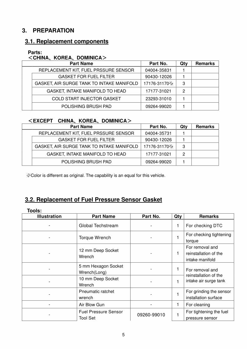
Tools: Illustration Part Name Part No. Qty Remarks
- Global Techstream - 1 For checking DTC
- Torque Wrench - 1 For checking tightening
torque
- 12 mm Deep Socket
Wrench - 1
For removal and
reinstallation of the
intake manifold -
5 mm Hexagon Socket
Wrench(Long) - 1 For removal and
reinstallation of the
intake air surge tank - 10 mm Deep Socket
Wrench - 1
- Pneumatic ratchet
wrench - 1
For grinding the sensor
installation surface
- Air Blow Gun - 1 For cleaning
- Fuel Pressure Sensor
Tool Set 09260-99010 1
For tightening the fuel
pressure sensor
6
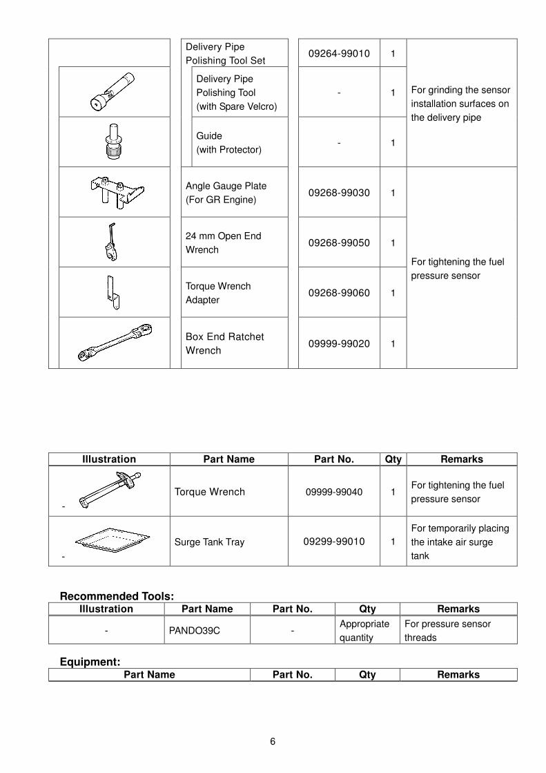
Delivery Pipe
Polishing Tool Set
09264-99010 1
For grinding the sensor
installation surfaces on
the delivery pipe
Delivery Pipe
Polishing Tool
(with Spare Velcro)
- 1
Guide
(with Protector) - 1
Angle Gauge Plate
(For GR Engine) 09268-99030 1
For tightening the fuel
pressure sensor
24 mm Open End
Wrench 09268-99050 1
Torque Wrench
Adapter 09268-99060 1
Box End Ratchet
Wrench 09999-99020 1
Illustration Part Name Part No. Qty Remarks
-
Torque Wrench 09999-99040 1 For tightening the fuel
pressure sensor
-
Surge Tank Tray 09299-99010 1
For temporarily placing
the intake air surge
tank
Recommended Tools:
Illustration Part Name Part No. Qty Remarks
- PANDO39C - Appropriate
quantity
For pressure sensor
threads
Equipment:
Part Name Part No. Qty Remarks
7
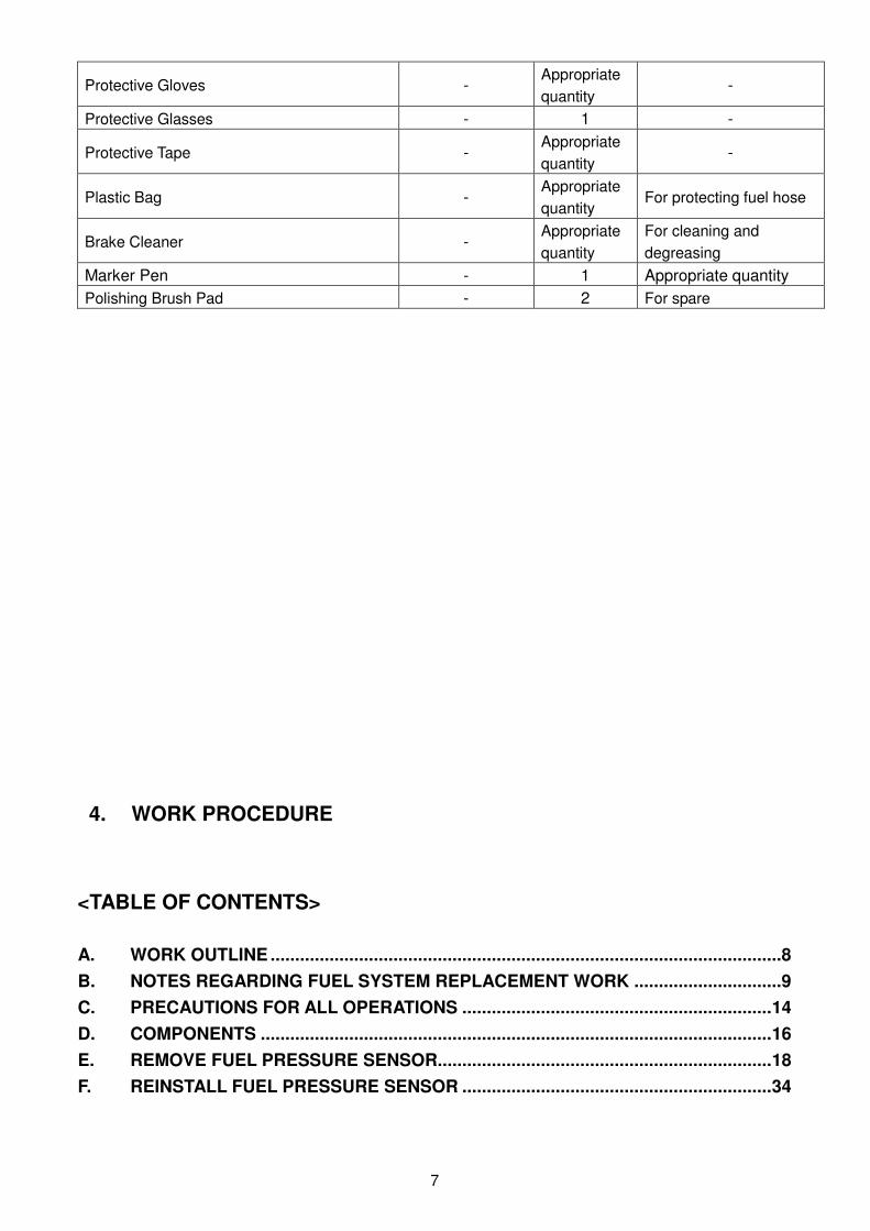
Protective Gloves - Appropriate
quantity -
Protective Glasses - 1 -
Protective Tape - Appropriate
quantity -
Plastic Bag - Appropriate
quantity For protecting fuel hose
Brake Cleaner - Appropriate
quantity
For cleaning and
degreasing
Marker Pen - 1 Appropriate quantity
Polishing Brush Pad - 2 For spare
4. WORK PROCEDURE
<TABLE OF CONTENTS>
A. WORK OUTLINE ........................................................................................................8
B. NOTES REGARDING FUEL SYSTEM REPLACEMENT WORK ..............................9
C. PRECAUTIONS FOR ALL OPERATIONS ............................................................... 14
D. COMPONENTS ........................................................................................................ 16
E. REMOVE FUEL PRESSURE SENSOR .................................................................... 18
F. REINSTALL FUEL PRESSURE SENSOR ............................................................... 34
8
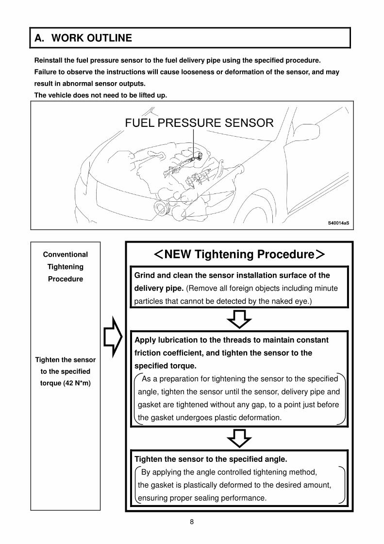
A. WORK OUTLINE
Reinstall the fuel pressure sensor to the fuel delivery pipe using the specified procedure.
Failure to observe the instructions will cause looseness or deformation of the sensor, and may
result in abnormal sensor outputs.
The vehicle does not need to be lifted up.
Conventional
Tightening
Procedure Tighten the sensor
to the specified
torque (42 N*m)
<<<<NEW Tightening Procedure>>>>
Grind and clean the sensor installation surface of the
delivery pipe. (Remove all foreign objects including minute
particles that cannot be detected by the naked eye.)
Apply lubrication to the threads to maintain constant
friction coefficient, and tighten the sensor to the
specified torque.
As a preparation for tightening the sensor to the specified
angle, tighten the sensor until the sensor, delivery pipe and
gasket are tightened without any gap, to a point just before
the gasket undergoes plastic deformation.
Tighten the sensor to the specified angle.
By applying the angle controlled tightening method,
the gasket is plastically deformed to the desired amount,
ensuring proper sealing performance.
9
B. NOTES REGARDING FUEL SYSTEM REPLACEMENT WORK
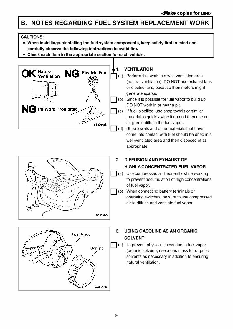
CAUTIONS:
•••• When installing/uninstalling the fuel system components, keep safety first in mind and
carefully observe the following instructions to avoid fire.
•••• Check each item in the appropriate section for each vehicle.
1. VENTILATION
(a) Perform this work in a well-ventilated area
(natural ventilation). DO NOT use exhaust fans
or electric fans, because their motors might
generate sparks.
(b) Since it is possible for fuel vapor to build up,
DO NOT work in or near a pit.
(c) If fuel is spilled, use shop towels or similar
material to quickly wipe it up and then use an
air gun to diffuse the fuel vapor.
(d) Shop towels and other materials that have
come into contact with fuel should be dried in a
well-ventilated area and then disposed of as
appropriate.
2. DIFFUSION AND EXHAUST OF
HIGHLY-CONCENTRATED FUEL VAPOR
(a) Use compressed air frequently while working
to prevent accumulation of high concentrations
of fuel vapor.
(b) When connecting battery terminals or
operating switches, be sure to use compressed
air to diffuse and ventilate fuel vapor.
3. USING GASOLINE AS AN ORGANIC
SOLVENT
(a) To prevent physical illness due to fuel vapor
(organic solvent), use a gas mask for organic
solvents as necessary in addition to ensuring
natural ventilation.
<Make copies for use> <Make copies for use>
10
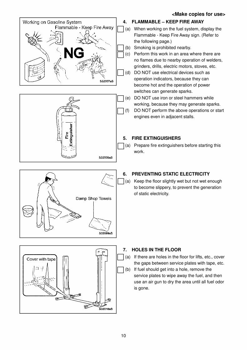
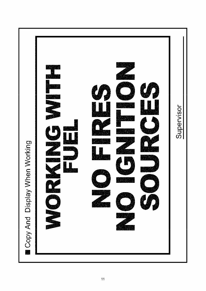
4. FLAMMABLE –––– KEEP FIRE AWAY
(a) When working on the fuel system, display the
Flammable - Keep Fire Away sign. (Refer to
the following page.)
(b) Smoking is prohibited nearby.
(c) Perform this work in an area where there are
no flames due to nearby operation of welders,
grinders, drills, electric motors, stoves, etc.
(d) DO NOT use electrical devices such as
operation indicators, because they can
become hot and the operation of power
switches can generate sparks.
(e) DO NOT use iron or steel hammers while
working, because they may generate sparks.
(f) DO NOT perform the above operations or start
engines even in adjacent stalls.
5. FIRE EXTINGUISHERS
(a) Prepare fire extinguishers before starting this
work.
6. PREVENTING STATIC ELECTRICITY
(a) Keep the floor slightly wet but not wet enough
to become slippery, to prevent the generation
of static electricity.
7. HOLES IN THE FLOOR
(a) If there are holes in the floor for lifts, etc., cover
the gaps between service plates with tape, etc.
(b) If fuel should get into a hole, remove the
service plates to wipe away the fuel, and then
use an air gun to dry the area until all fuel odor
is gone.
<Make copies for use>
11
12
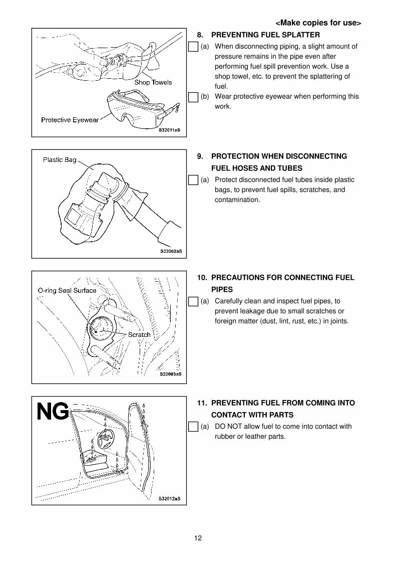
8. PREVENTING FUEL SPLATTER
(a) When disconnecting piping, a slight amount of
pressure remains in the pipe even after
performing fuel spill prevention work. Use a
shop towel, etc. to prevent the splattering of
fuel.
(b) Wear protective eyewear when performing this
work.
9. PROTECTION WHEN DISCONNECTING
FUEL HOSES AND TUBES
(a) Protect disconnected fuel tubes inside plastic
bags, to prevent fuel spills, scratches, and
contamination.
10. PRECAUTIONS FOR CONNECTING FUEL
PIPES
(a) Carefully clean and inspect fuel pipes, to
prevent leakage due to small scratches or
foreign matter (dust, lint, rust, etc.) in joints.
11. PREVENTING FUEL FROM COMING INTO
CONTACT WITH PARTS
(a) DO NOT allow fuel to come into contact with
rubber or leather parts.
<Make copies for use>
13
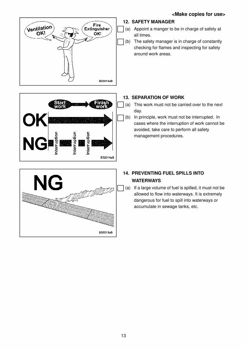
12. SAFETY MANAGER
(a) Appoint a manger to be in charge of safety at
all times.
(b) The safety manager is in charge of constantly
checking for flames and inspecting for safety
around work areas.
13. SEPARATION OF WORK
(a) This work must not be carried over to the next
day.
(b) In principle, work must not be interrupted. In
cases where the interruption of work cannot be
avoided, take care to perform all safety
management procedures.
14. PREVENTING FUEL SPILLS INTO
WATERWAYS
(a) If a large volume of fuel is spilled, it must not be
allowed to flow into waterways. It is extremely
dangerous for fuel to spill into waterways or
accumulate in sewage tanks, etc.
<Make copies for use>
14
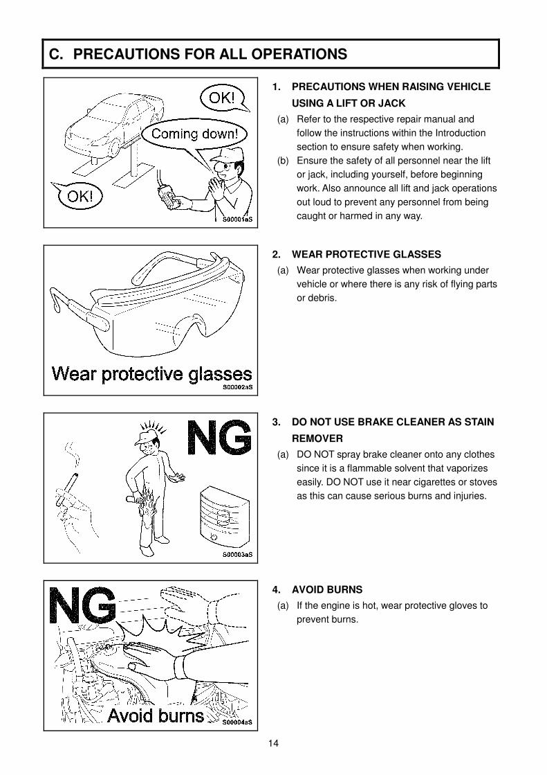
C. PRECAUTIONS FOR ALL OPERATIONS
1. PRECAUTIONS WHEN RAISING VEHICLE
USING A LIFT OR JACK
(a) Refer to the respective repair manual and
follow the instructions within the Introduction
section to ensure safety when working.
(b) Ensure the safety of all personnel near the lift
or jack, including yourself, before beginning
work. Also announce all lift and jack operations
out loud to prevent any personnel from being
caught or harmed in any way.
2. WEAR PROTECTIVE GLASSES
(a) Wear protective glasses when working under
vehicle or where there is any risk of flying parts
or debris.
3. DO NOT USE BRAKE CLEANER AS STAIN
REMOVER
(a) DO NOT spray brake cleaner onto any clothes
since it is a flammable solvent that vaporizes
easily. DO NOT use it near cigarettes or stoves
as this can cause serious burns and injuries.
4. AVOID BURNS
(a) If the engine is hot, wear protective gloves to
prevent burns.
15
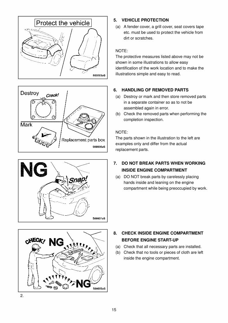
5. VEHICLE PROTECTION
(a) A fender cover, a grill cover, seat covers tape
etc. must be used to protect the vehicle from
dirt or scratches.
NOTE:
The protective measures listed above may not be
shown in some illustrations to allow easy
identification of the work location and to make the
illustrations simple and easy to read.
6. HANDLING OF REMOVED PARTS
(a) Destroy or mark and then store removed parts
in a separate container so as to not be
assembled again in error.
(b) Check the removed parts when performing the
completion inspection.
NOTE:
The parts shown in the illustration to the left are
examples only and differ from the actual
replacement parts.
7. DO NOT BREAK PARTS WHEN WORKING
INSIDE ENGINE COMPARTMENT
(a) DO NOT break parts by carelessly placing
hands inside and leaning on the engine
compartment while being preoccupied by work.
8. CHECK INSIDE ENGINE COMPARTMENT
BEFORE ENGINE START-UP
(a) Check that all necessary parts are installed.
(b) Check that no tools or pieces of cloth are left
inside the engine compartment.
2.
16
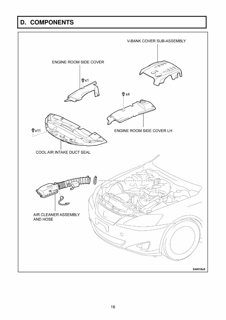
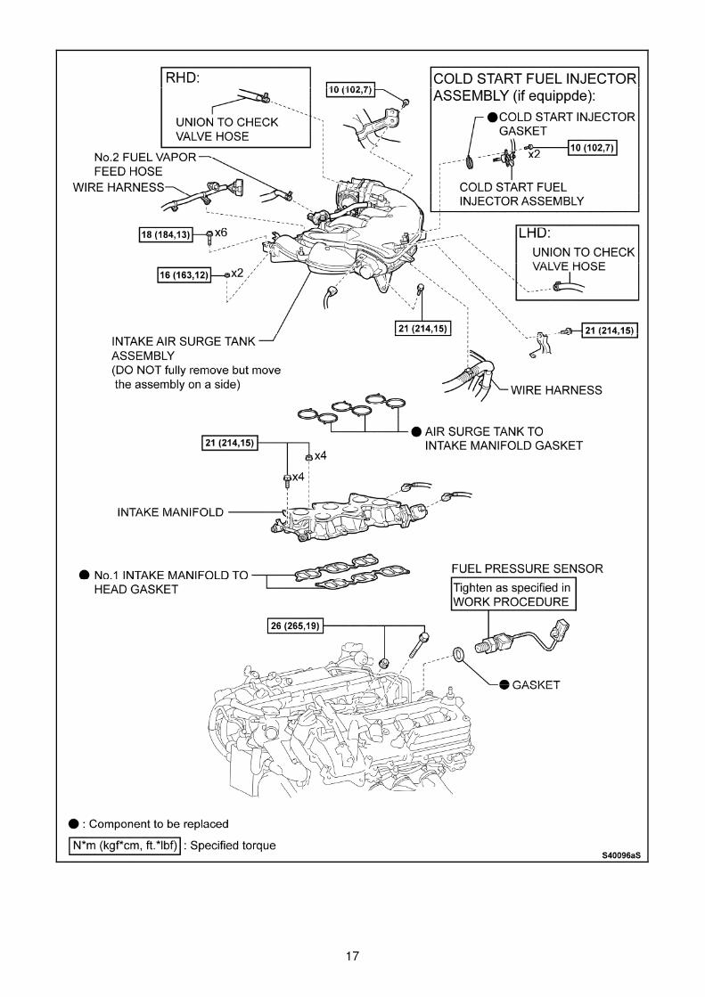
D. COMPONENTS
17
18
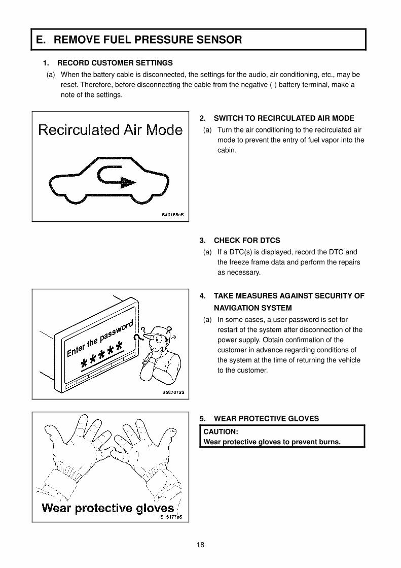
E. REMOVE FUEL PRESSURE SENSOR
1. RECORD CUSTOMER SETTINGS
(a) When the battery cable is disconnected, the settings for the audio, air conditioning, etc., may be
reset. Therefore, before disconnecting the cable from the negative (-) battery terminal, make a
note of the settings.
2. SWITCH TO RECIRCULATED AIR MODE (a) Turn the air conditioning to the recirculated air
mode to prevent the entry of fuel vapor into the
cabin.
3. CHECK FOR DTCS (a) If a DTC(s) is displayed, record the DTC and
the freeze frame data and perform the repairs
as necessary.
4. TAKE MEASURES AGAINST SECURITY OF
NAVIGATION SYSTEM (a) In some cases, a user password is set for
restart of the system after disconnection of the
power supply. Obtain confirmation of the
customer in advance regarding conditions of
the system at the time of returning the vehicle
to the customer.
5. WEAR PROTECTIVE GLOVES
CAUTION:
Wear protective gloves to prevent burns.
19
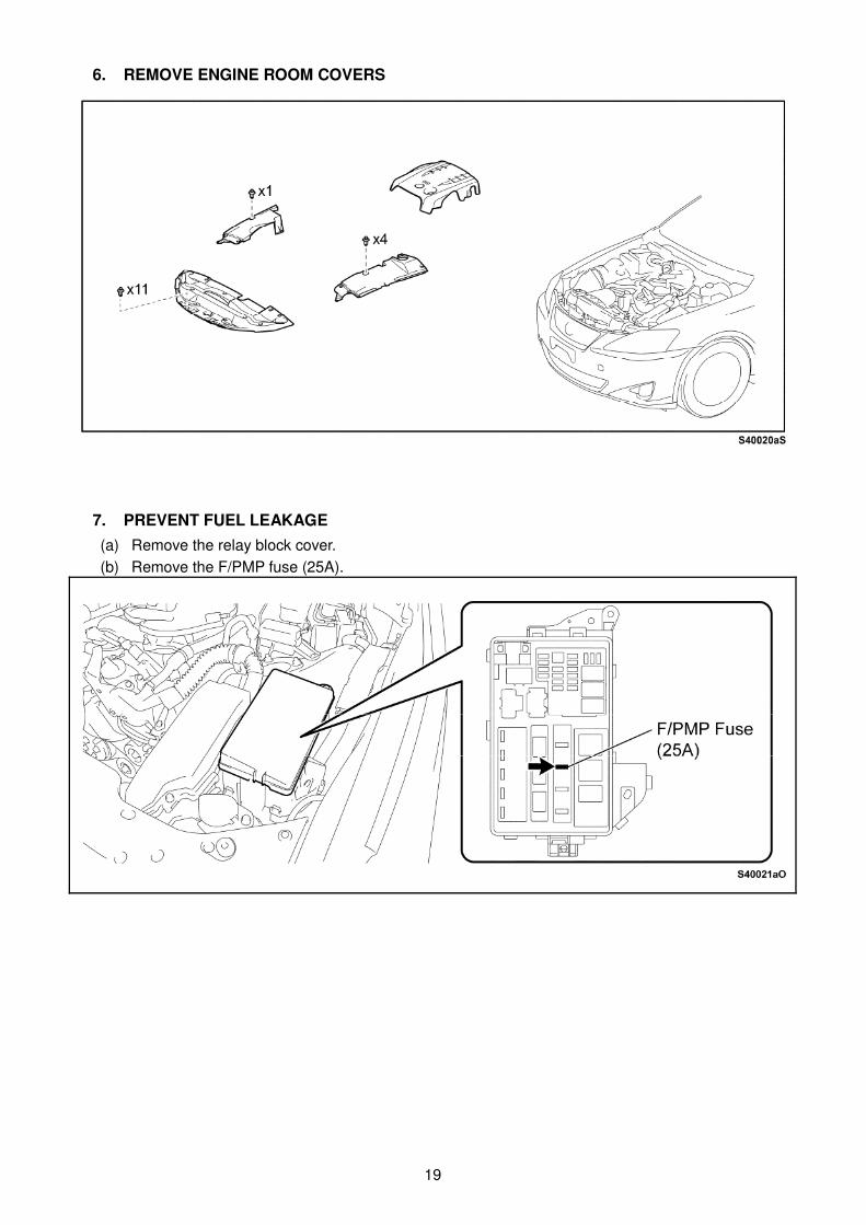
6. REMOVE ENGINE ROOM COVERS
7. PREVENT FUEL LEAKAGE
(a) Remove the relay block cover.
(b) Remove the F/PMP fuse (25A).

20
(c) Turn the engine switch on to start the engine.
(d) Confirm that the engine stops automatically
and then turn the engine switch off. NOTE: ・・・・ On some vehicles, it may take several minutes
for the engine to stop. ・・・・ DTCs may be output.
P0087: Fuel Rail / System Pressure – Too Low
P1603: Engine Stall History
P1604: Startability Malfunction
P1605: Rough Idling
P0171: System Too Lean (Bank 1)
P0174: System Too Lean (Bank 2)
P0191: Fuel Pressure Sensor Signal Error
P0230: Fuel Pump Primary Circuit
(e) Crank the engine again and make sure that the
engine does not start.
8. REMOVE FUEL TANK CAP ASSEMBLY
CAUTION:
DO NOT reinstall the cap until instructed, to
prevent fuel leakage caused by a pressure rise
inside the fuel tank.
9. DISCONNECT CABLE FROM NEGATIVE
BATTERY TERMINAL (a) Disconnect the cable from the negative (-)
battery terminal to prevent sparks.
CAUTION:
For models with a HDD navigation system, wait
at least 6 minutes before disconnecting the
battery. It takes approximately 6 minutes for
the system to save information and settings
after the engine switch is turned off.
21
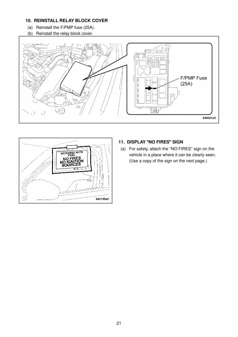
10. REINSTALL RELAY BLOCK COVER
(a) Reinstall the F/PMP fuse (25A).
(b) Reinstall the relay block cover.
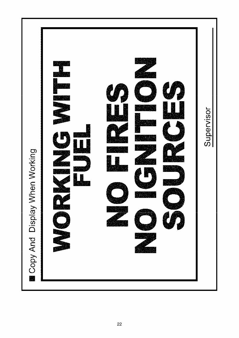
11. DISPLAY ““““NO FIRES”””” SIGN
(a) For safety, attach the “NO FIRES” sign on the
vehicle in a place where it can be clearly seen.
(Use a copy of the sign on the next page.)
22
23
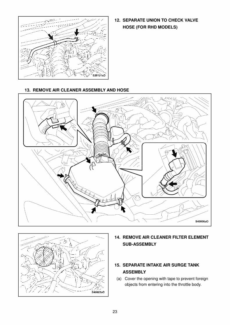
12. SEPARATE UNION TO CHECK VALVE
HOSE (FOR RHD MODELS)
13. REMOVE AIR CLEANER ASSEMBLY AND HOSE
14. REMOVE AIR CLEANER FILTER ELEMENT
SUB-ASSEMBLY
15. SEPARATE INTAKE AIR SURGE TANK
ASSEMBLY (a) Cover the opening with tape to prevent foreign
objects from entering into the throttle body.

24
(b) Disconnect the throttle body connector.
(c) Disconnect the No.2 fuel vapor feed hose.
(d) Disconnect the vacuum switching valve
connector.
(e) Disengage the 2 wire harness clamps and
disconnect the No.2 water by-pass hose from
the intake air surge tank.
(f) Using the supplied box end ratchet wrench,
remove the bolt from the water pipe stay.
25
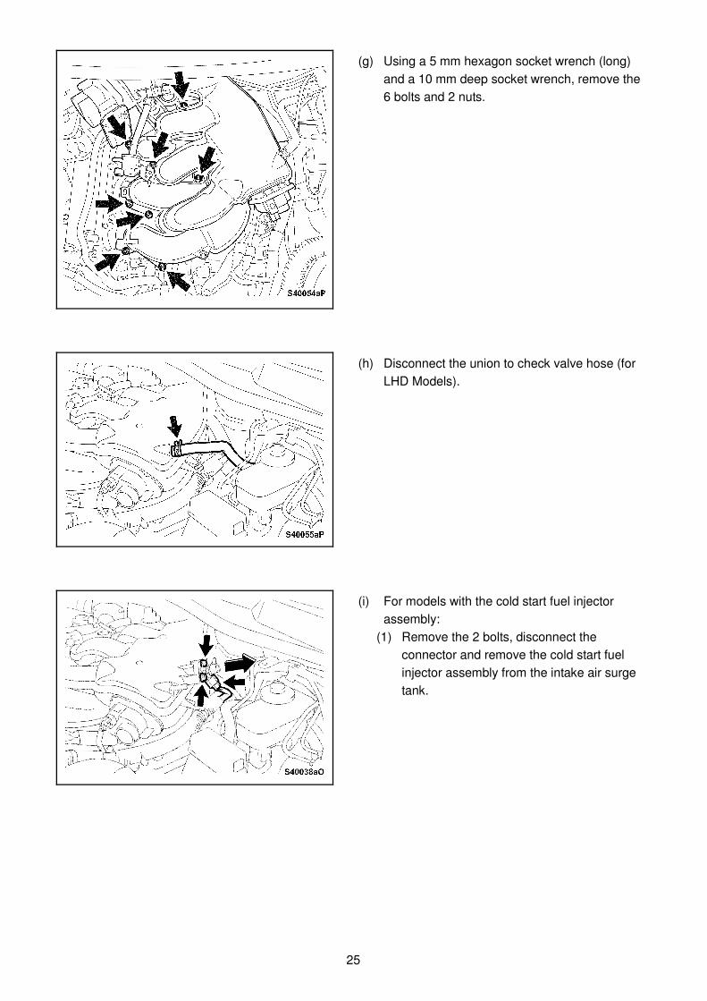
(g) Using a 5 mm hexagon socket wrench (long)
and a 10 mm deep socket wrench, remove the
6 bolts and 2 nuts.
(h) Disconnect the union to check valve hose (for
LHD Models).
(i) For models with the cold start fuel injector
assembly:
(1) Remove the 2 bolts, disconnect the
connector and remove the cold start fuel
injector assembly from the intake air surge
tank.
26
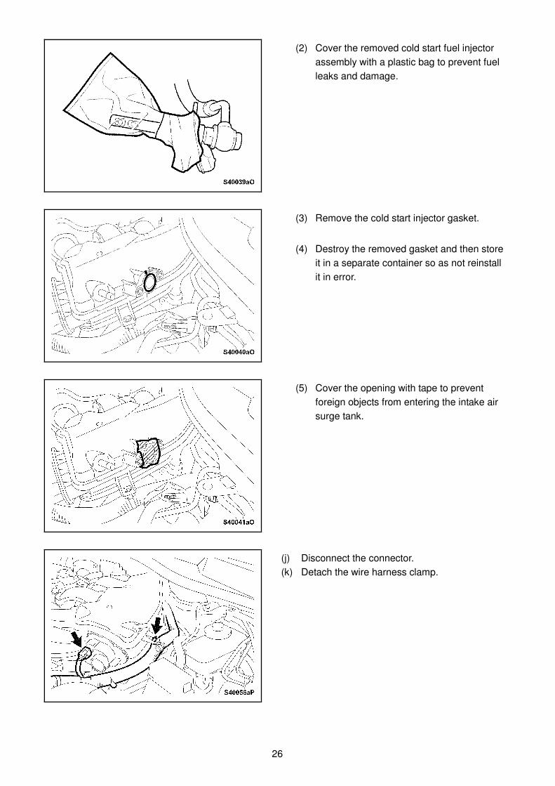
(2) Cover the removed cold start fuel injector
assembly with a plastic bag to prevent fuel
leaks and damage.
(3) Remove the cold start injector gasket.
(4) Destroy the removed gasket and then store
it in a separate container so as not reinstall
it in error.
(5) Cover the opening with tape to prevent
foreign objects from entering the intake air
surge tank.
(j) Disconnect the connector.
(k) Detach the wire harness clamp.
27
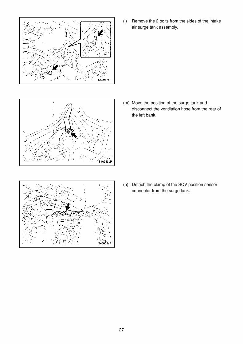
(l) Remove the 2 bolts from the sides of the intake
air surge tank assembly.
(m) Move the position of the surge tank and
disconnect the ventilation hose from the rear of
the left bank.
(n) Detach the clamp of the SCV position sensor
connector from the surge tank.
28
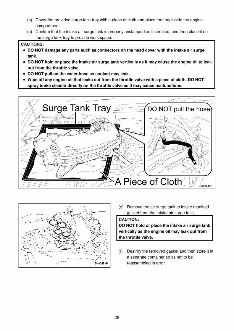
(o) Cover the provided surge tank tray with a piece of cloth and place the tray inside the engine
compartment.
(p) Confirm that the intake air surge tank is properly unclamped as instructed, and then place it on
the surge tank tray to provide work space.
CAUTIONS:
•••• DO NOT damage any parts such as connectors on the head cover with the intake air surge
tank. •••• DO NOT hold or place the intake air surge tank vertically as it may cause the engine oil to leak
out from the throttle valve.
•••• DO NOT pull on the water hose as coolant may leak. •••• Wipe off any engine oil that leaks out from the throttle valve with a piece of cloth. DO NOT
spray brake cleaner directly on the throttle valve as it may cause malfunctions.
(q) Remove the air surge tank to intake manifold
gasket from the intake air surge tank.
CAUTION: DO NOT hold or place the intake air surge tank
vertically as the engine oil may leak out from
the throttle valve.
(r) Destroy the removed gasket and then store it in
a separate container so as not to be
reassembled in error.
29
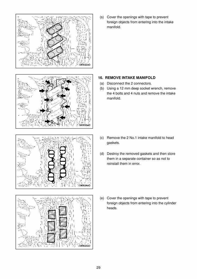
(s) Cover the openings with tape to prevent
foreign objects from entering into the intake
manifold.
16. REMOVE INTAKE MANIFOLD
(a) Disconnect the 2 connectors.
(b) Using a 12 mm deep socket wrench, remove
the 4 bolts and 4 nuts and remove the intake
manifold.
(c) Remove the 2 No.1 intake manifold to head
gaskets.
(d) Destroy the removed gaskets and then store
them in a separate container so as not to
reinstall them in error.
(e) Cover the openings with tape to prevent
foreign objects from entering into the cylinder
heads.
30
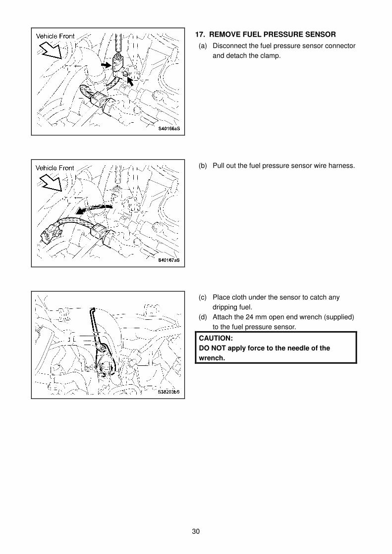
17. REMOVE FUEL PRESSURE SENSOR
(a) Disconnect the fuel pressure sensor connector
and detach the clamp.
(b) Pull out the fuel pressure sensor wire harness.
(c) Place cloth under the sensor to catch any
dripping fuel.
(d) Attach the 24 mm open end wrench (supplied)
to the fuel pressure sensor.
CAUTION:
DO NOT apply force to the needle of the
wrench.
31
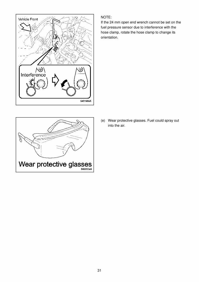
NOTE:
If the 24 mm open end wrench cannot be set on the
fuel pressure sensor due to interference with the
hose clamp, rotate the hose clamp to change its
orientation.
(e) Wear protective glasses. Fuel could spray out
into the air.
32
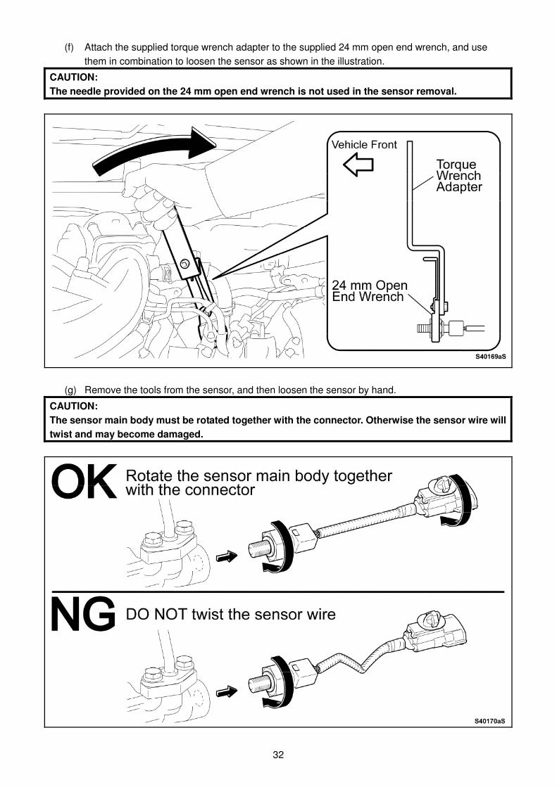
(f) Attach the supplied torque wrench adapter to the supplied 24 mm open end wrench, and use
them in combination to loosen the sensor as shown in the illustration.
CAUTION:
The needle provided on the 24 mm open end wrench is not used in the sensor removal.
(g) Remove the tools from the sensor, and then loosen the sensor by hand.
CAUTION:
The sensor main body must be rotated together with the connector. Otherwise the sensor wire will
twist and may become damaged.
33
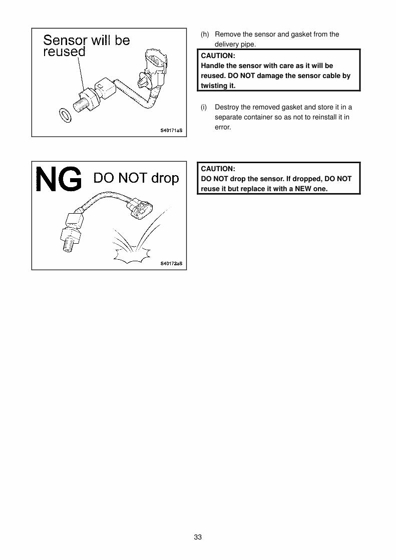
(h) Remove the sensor and gasket from the
delivery pipe.
CAUTION:
Handle the sensor with care as it will be
reused. DO NOT damage the sensor cable by
twisting it.
(i) Destroy the removed gasket and store it in a
separate container so as not to reinstall it in
error.
CAUTION:
DO NOT drop the sensor. If dropped, DO NOT
reuse it but replace it with a NEW one.
34
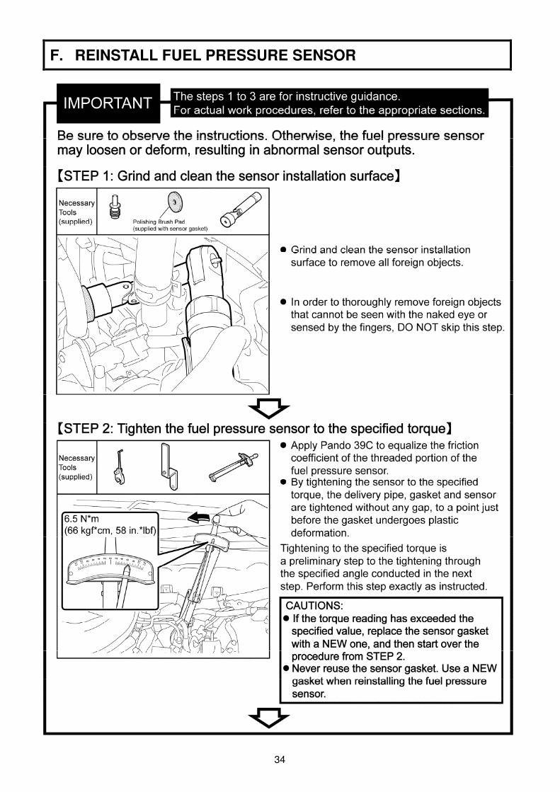
F. REINSTALL FUEL PRESSURE SENSOR
35
36
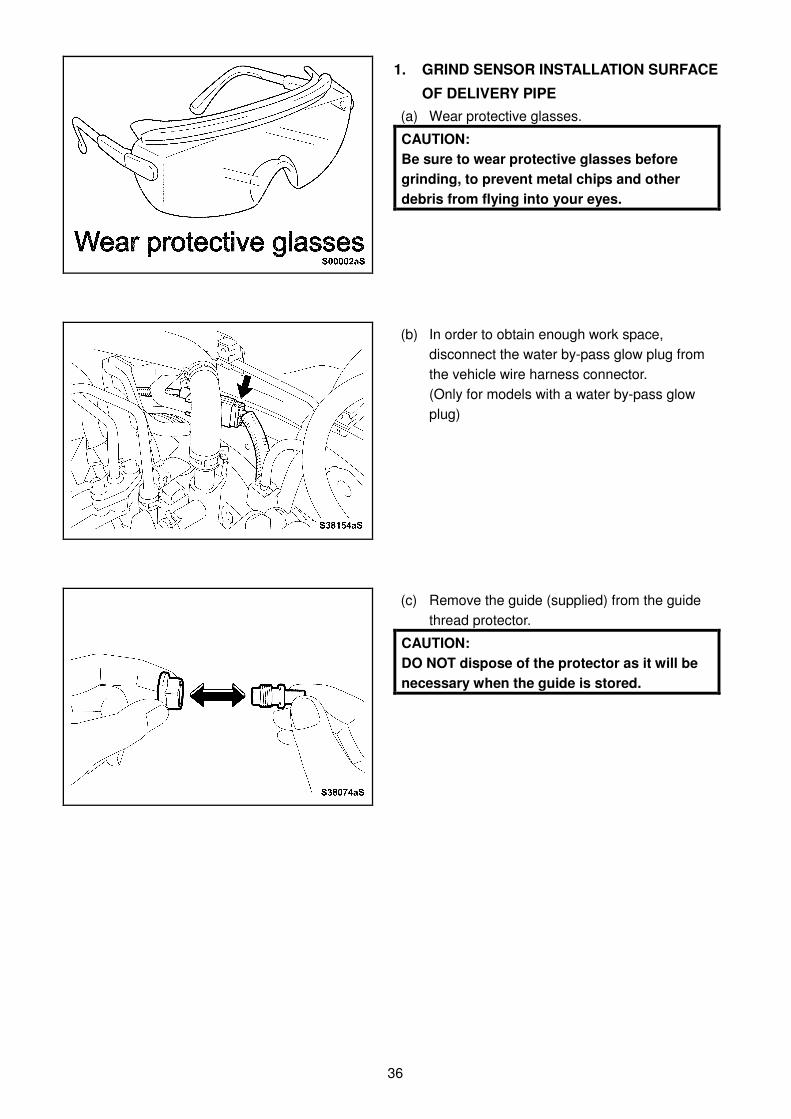
1. GRIND SENSOR INSTALLATION SURFACE
OF DELIVERY PIPE
(a) Wear protective glasses.
CAUTION:
Be sure to wear protective glasses before
grinding, to prevent metal chips and other
debris from flying into your eyes.
(b) In order to obtain enough work space,
disconnect the water by-pass glow plug from
the vehicle wire harness connector.
(Only for models with a water by-pass glow
plug)
(c) Remove the guide (supplied) from the guide
thread protector.
CAUTION:
DO NOT dispose of the protector as it will be
necessary when the guide is stored.
37
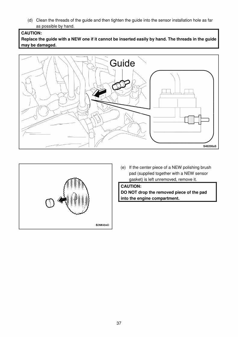
(d) Clean the threads of the guide and then tighten the guide into the sensor installation hole as far
as possible by hand.
CAUTION:
Replace the guide with a NEW one if it cannot be inserted easily by hand. The threads in the guide
may be damaged.
(e) If the center piece of a NEW polishing brush
pad (supplied together with a NEW sensor
gasket) is left unremoved, remove it.
CAUTION:
DO NOT drop the removed piece of the pad
into the engine compartment.
38
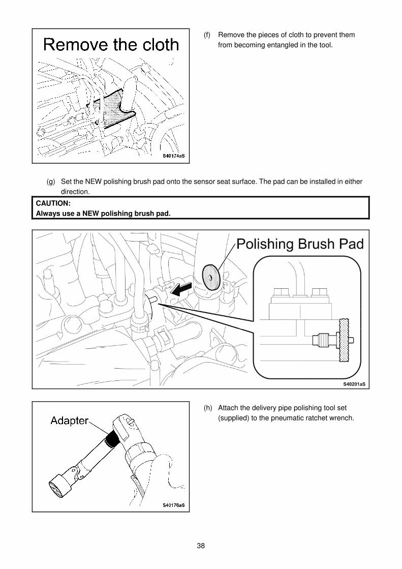
(f) Remove the pieces of cloth to prevent them
from becoming entangled in the tool.
(g) Set the NEW polishing brush pad onto the sensor seat surface. The pad can be installed in either
direction.
CAUTION:
Always use a NEW polishing brush pad.
(h) Attach the delivery pipe polishing tool set
(supplied) to the pneumatic ratchet wrench.
39
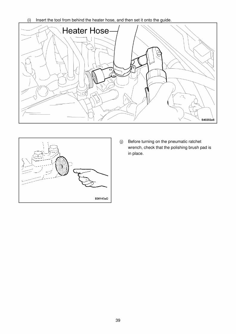
(i) Insert the tool from behind the heater hose, and then set it onto the guide.
(j) Before turning on the pneumatic ratchet
wrench, check that the polishing brush pad is
in place.
40
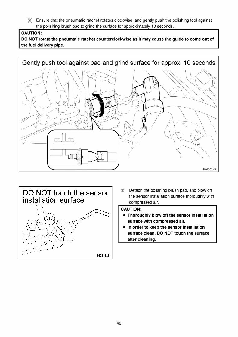
(k) Ensure that the pneumatic ratchet rotates clockwise, and gently push the polishing tool against
the polishing brush pad to grind the surface for approximately 10 seconds. CAUTION:
DO NOT rotate the pneumatic ratchet counterclockwise as it may cause the guide to come out of
the fuel delivery pipe.
(l) Detach the polishing brush pad, and blow off
the sensor installation surface thoroughly with
compressed air.
CAUTION:
•••• Thoroughly blow off the sensor installation
surface with compressed air.
•••• In order to keep the sensor installation
surface clean, DO NOT touch the surface
after cleaning.
41
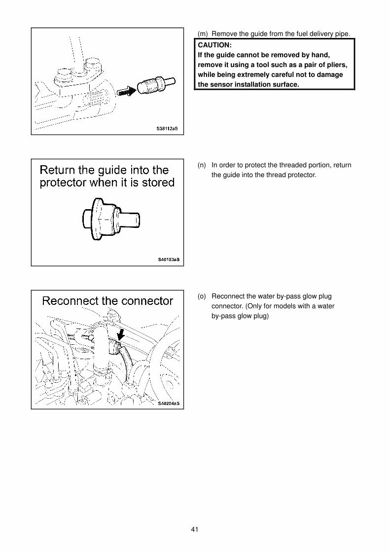
(m) Remove the guide from the fuel delivery pipe.
CAUTION:
If the guide cannot be removed by hand,
remove it using a tool such as a pair of pliers,
while being extremely careful not to damage
the sensor installation surface.
(n) In order to protect the threaded portion, return
the guide into the thread protector.
(o) Reconnect the water by-pass glow plug
connector. (Only for models with a water
by-pass glow plug)

42
2. TIGHTEN FUEL PRESSURE SENSOR TO
SPECIFIED TORQUE
(a) Check a NEW gasket and the sensor for any
damage or adhesion of foreign objects. (b) Install the NEW gasket to the fuel pressure
sensor.
(c) Spray Pando 39C (supplied) all over the
threaded portion of the sensor.
CAUTION:
DO NOT spray Pando 39C onto the connector.
(d) Tighten the sensor onto the fuel delivery pipe by hand. CAUTION:
The sensor main body must be rotated together with the connector. Otherwise the sensor wire will
twist and may become damaged.
43
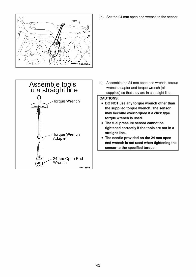
(e) Set the 24 mm open end wrench to the sensor.
(f) Assemble the 24 mm open end wrench, torque
wrench adapter and torque wrench (all
supplied) so that they are in a straight line.
CAUTIONS:
•••• DO NOT use any torque wrench other than
the supplied torque wrench. The sensor
may become overtorqued if a click type
torque wrench is used.
•••• The fuel pressure sensor cannot be
tightened correctly if the tools are not in a
straight line.
•••• The needle provided on the 24 mm open
end wrench is not used when tightening the
sensor to the specified torque.
44
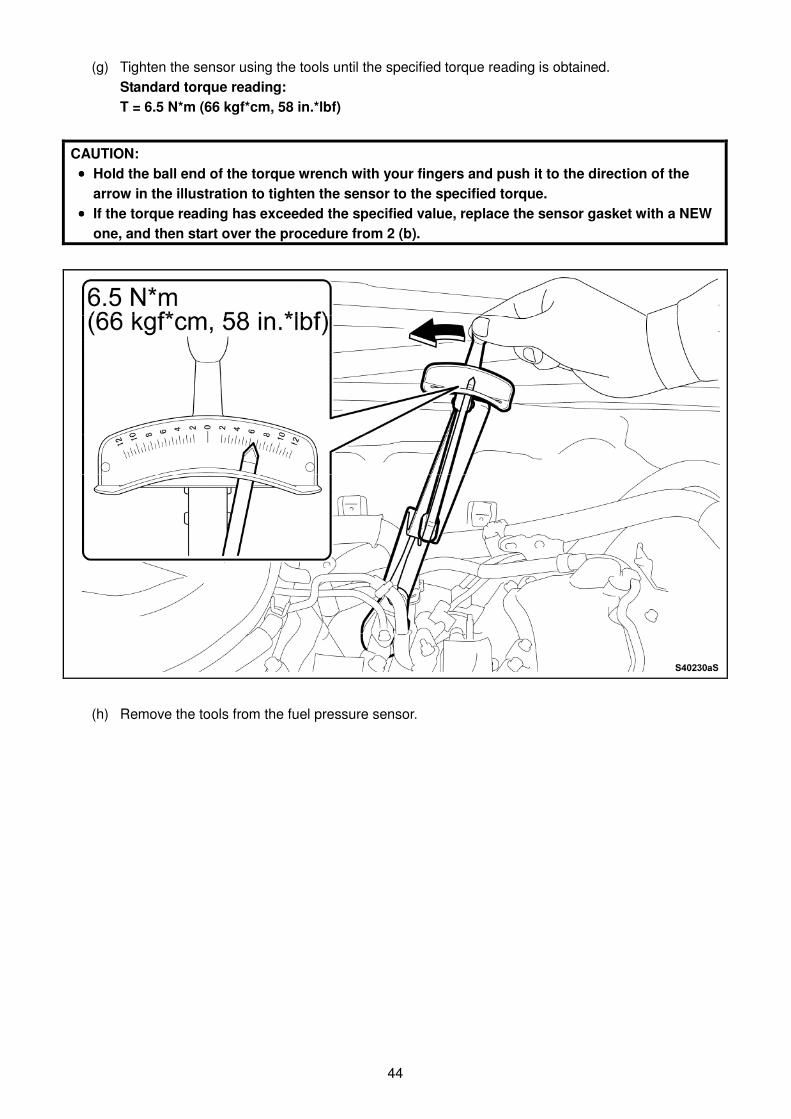
(g) Tighten the sensor using the tools until the specified torque reading is obtained.
Standard torque reading:
T = 6.5 N*m (66 kgf*cm, 58 in.*lbf)
CAUTION:
•••• Hold the ball end of the torque wrench with your fingers and push it to the direction of the
arrow in the illustration to tighten the sensor to the specified torque.
•••• If the torque reading has exceeded the specified value, replace the sensor gasket with a NEW
one, and then start over the procedure from 2 (b).
(h) Remove the tools from the fuel pressure sensor.
45
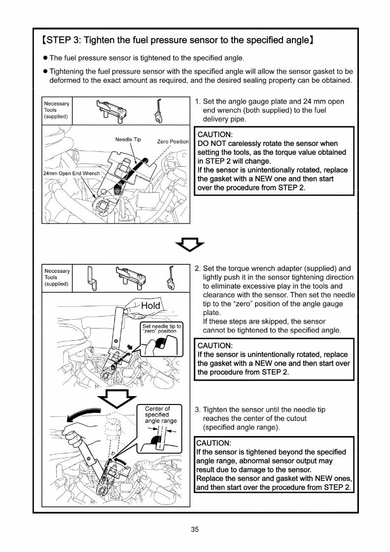
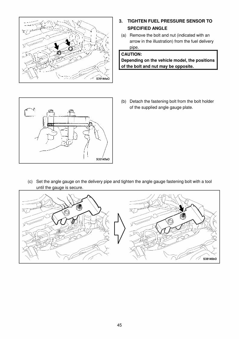
3. TIGHTEN FUEL PRESSURE SENSOR TO
SPECIFIED ANGLE
(a) Remove the bolt and nut (indicated with an
arrow in the illustration) from the fuel delivery
pipe.
CAUTION:
Depending on the vehicle model, the positions
of the bolt and nut may be opposite.
(b) Detach the fastening bolt from the bolt holder
of the supplied angle gauge plate.
(c) Set the angle gauge on the delivery pipe and tighten the angle gauge fastening bolt with a tool
until the gauge is secure.
46
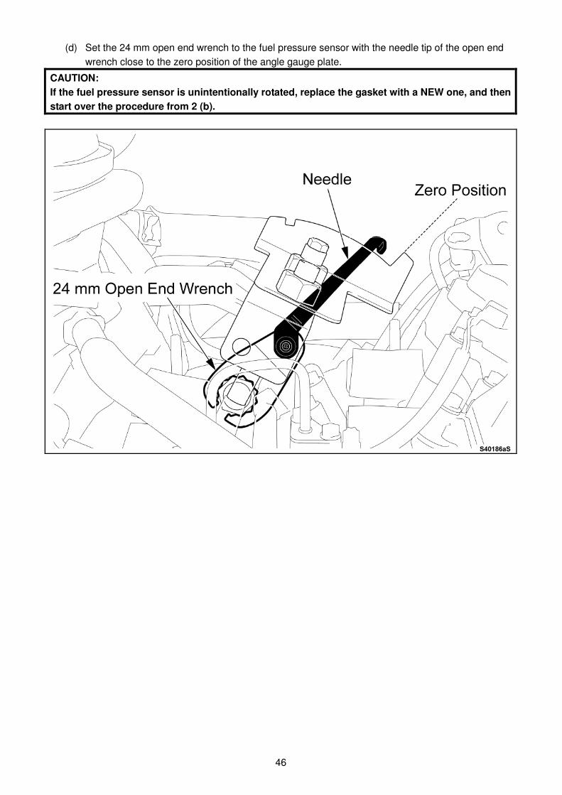
(d) Set the 24 mm open end wrench to the fuel pressure sensor with the needle tip of the open end
wrench close to the zero position of the angle gauge plate.
CAUTION:
If the fuel pressure sensor is unintentionally rotated, replace the gasket with a NEW one, and then
start over the procedure from 2 (b).
47
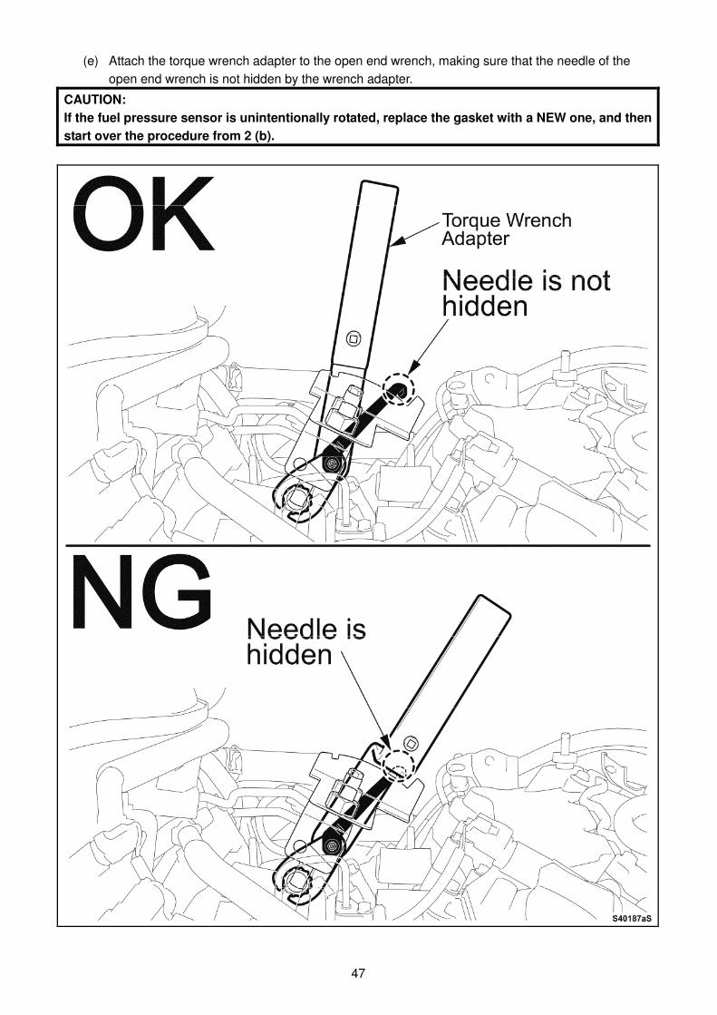
(e) Attach the torque wrench adapter to the open end wrench, making sure that the needle of the
open end wrench is not hidden by the wrench adapter.
CAUTION:
If the fuel pressure sensor is unintentionally rotated, replace the gasket with a NEW one, and then
start over the procedure from 2 (b).
48
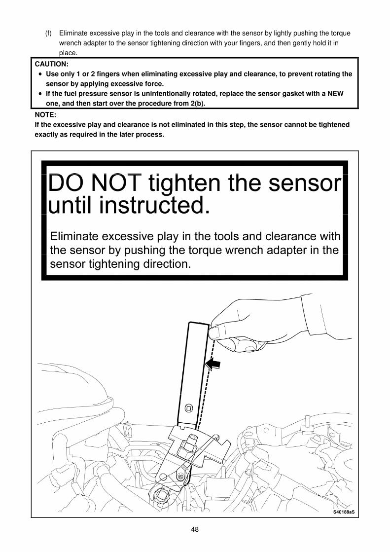
(f) Eliminate excessive play in the tools and clearance with the sensor by lightly pushing the torque
wrench adapter to the sensor tightening direction with your fingers, and then gently hold it in
place.
CAUTION:
•••• Use only 1 or 2 fingers when eliminating excessive play and clearance, to prevent rotating the
sensor by applying excessive force.
•••• If the fuel pressure sensor is unintentionally rotated, replace the sensor gasket with a NEW
one, and then start over the procedure from 2(b).
NOTE:
If the excessive play and clearance is not eliminated in this step, the sensor cannot be tightened
exactly as required in the later process.
49
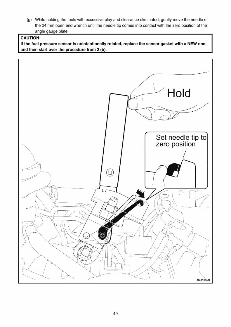
(g) While holding the tools with excessive play and clearance eliminated, gently move the needle of
the 24 mm open end wrench until the needle tip comes into contact with the zero position of the
angle gauge plate.
CAUTION:
If the fuel pressure sensor is unintentionally rotated, replace the sensor gasket with a NEW one,
and then start over the procedure from 2 (b).
50
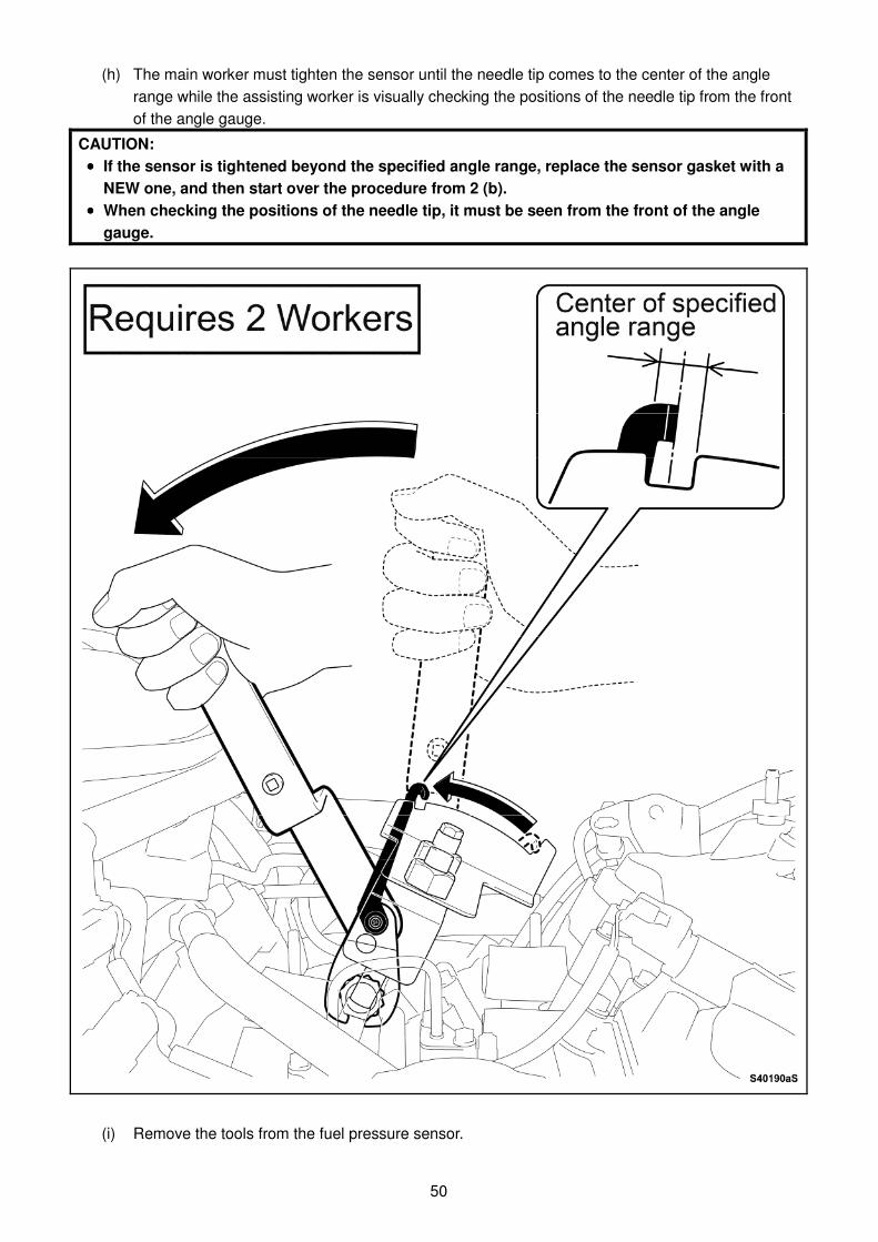
(h) The main worker must tighten the sensor until the needle tip comes to the center of the angle
range while the assisting worker is visually checking the positions of the needle tip from the front
of the angle gauge.
CAUTION:
•••• If the sensor is tightened beyond the specified angle range, replace the sensor gasket with a
NEW one, and then start over the procedure from 2 (b).
•••• When checking the positions of the needle tip, it must be seen from the front of the angle
gauge.
(i) Remove the tools from the fuel pressure sensor.
51
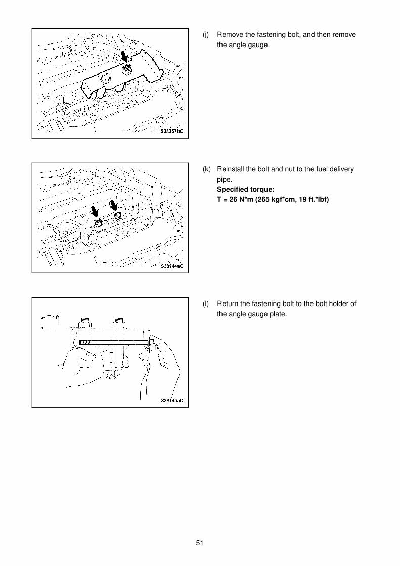
(j) Remove the fastening bolt, and then remove
the angle gauge.
(k) Reinstall the bolt and nut to the fuel delivery
pipe.
Specified torque:
T = 26 N*m (265 kgf*cm, 19 ft.*lbf)
(l) Return the fastening bolt to the bolt holder of
the angle gauge plate.
52
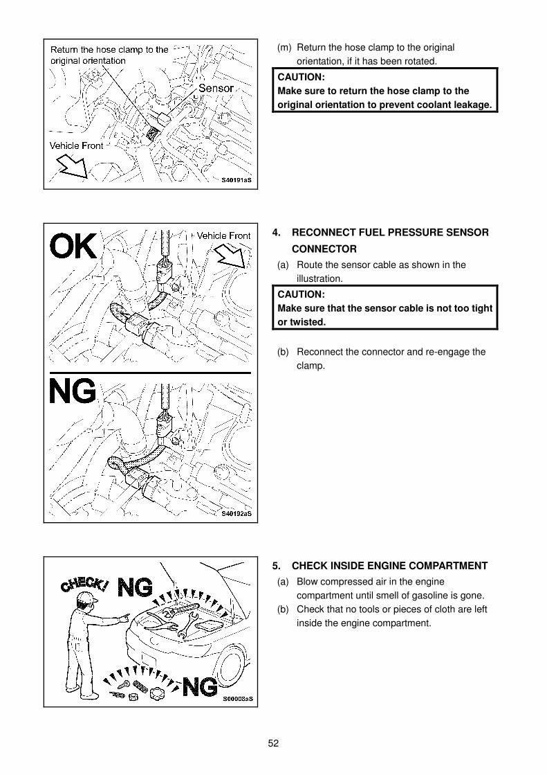
(m) Return the hose clamp to the original
orientation, if it has been rotated.
CAUTION:
Make sure to return the hose clamp to the
original orientation to prevent coolant leakage.
4. RECONNECT FUEL PRESSURE SENSOR
CONNECTOR
(a) Route the sensor cable as shown in the
illustration.
CAUTION:
Make sure that the sensor cable is not too tight
or twisted.
(b) Reconnect the connector and re-engage the
clamp.
5. CHECK INSIDE ENGINE COMPARTMENT
(a) Blow compressed air in the engine
compartment until smell of gasoline is gone. (b) Check that no tools or pieces of cloth are left
inside the engine compartment.
53
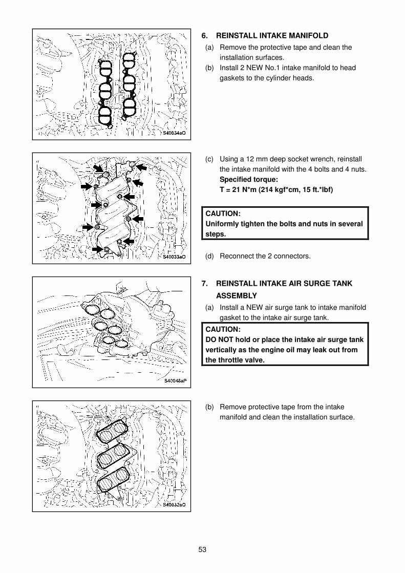
6. REINSTALL INTAKE MANIFOLD
(a) Remove the protective tape and clean the
installation surfaces. (b) Install 2 NEW No.1 intake manifold to head
gaskets to the cylinder heads.
(c) Using a 12 mm deep socket wrench, reinstall
the intake manifold with the 4 bolts and 4 nuts.
Specified torque:
T = 21 N*m (214 kgf*cm, 15 ft.*lbf)
CAUTION:
Uniformly tighten the bolts and nuts in several
steps.
(d) Reconnect the 2 connectors.
7. REINSTALL INTAKE AIR SURGE TANK ASSEMBLY
(a) Install a NEW air surge tank to intake manifold
gasket to the intake air surge tank.
CAUTION:
DO NOT hold or place the intake air surge tank
vertically as the engine oil may leak out from
the throttle valve.
(b) Remove protective tape from the intake
manifold and clean the installation surface.

54
(c) Re-attach the SCV position sensor connector
clamp to the surge tank.
(d) Temporarily install the intake air surge tank while being careful not to damage the gasket by the
stud bolts.
(e) Check the throttle body for disconnection of the water hose.

55
(f) Reconnect the ventilation hose.
(g) Temporarily reinstall the 2 bolts to the sides of
the intake air surge tank.
(h) Using the supplied box end ratchet wrench,
temporarily tighten the bolt onto the water pipe
stay.
CAUTION:
The stay must be temporarily reinstalled with
the 3 bolts. Otherwise, the bolts and the bolt
holes will become misaligned.
(i) Using a 5 mm hexagon socket wrench (long)
and a 10 mm deep socket wrench, uniformly
tighten the 6 bolts and 2 nuts to the specified
torques.
Specified torque:
T = 18 N*m (184 kgf*cm, 13 ft.*lbf) (Bolt)
T = 16 N*m (163 kgf*cm, 12 ft.*lbf) (Nut)
56
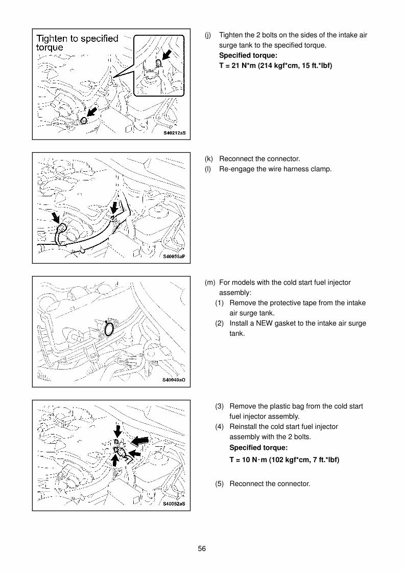
(j) Tighten the 2 bolts on the sides of the intake air
surge tank to the specified torque.
Specified torque:
T = 21 N*m (214 kgf*cm, 15 ft.*lbf)
(k) Reconnect the connector.
(l) Re-engage the wire harness clamp.
(m) For models with the cold start fuel injector
assembly:
(1) Remove the protective tape from the intake
air surge tank.
(2) Install a NEW gasket to the intake air surge
tank.
(3) Remove the plastic bag from the cold start
fuel injector assembly.
(4) Reinstall the cold start fuel injector
assembly with the 2 bolts.
Specified torque:
T = 10 N・・・・m (102 kgf*cm, 7 ft.*lbf)
(5) Reconnect the connector.
57
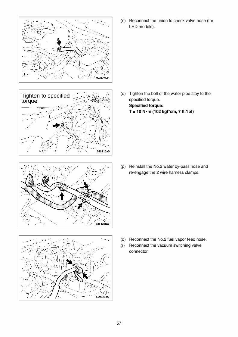
(n) Reconnect the union to check valve hose (for
LHD models).
(o) Tighten the bolt of the water pipe stay to the
specified torque.
Specified torque:
T = 10 N・・・・m (102 kgf*cm, 7 ft.*lbf)
(p) Reinstall the No.2 water by-pass hose and
re-engage the 2 wire harness clamps.
(q) Reconnect the No.2 fuel vapor feed hose.
(r) Reconnect the vacuum switching valve
connector.

58
(s) Reconnect the connector to the throttle body.
(t) Remove the protective tape.
(u) Clean the throttle body.
8. REINSTALL AIR FILTER ELEMENT
SUB-ASSEMBLY
9. REINSTALL AIR CLEANER ASSEMBLY AND HOSE
59
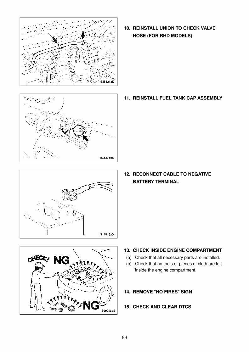
10. REINSTALL UNION TO CHECK VALVE
HOSE (FOR RHD MODELS)
11. REINSTALL FUEL TANK CAP ASSEMBLY
12. RECONNECT CABLE TO NEGATIVE
BATTERY TERMINAL
13. CHECK INSIDE ENGINE COMPARTMENT (a) Check that all necessary parts are installed.
(b) Check that no tools or pieces of cloth are left
inside the engine compartment.
14. REMOVE ““““NO FIRES”””” SIGN
15. CHECK AND CLEAR DTCS
60
16. INSPECT THROTTLE BODY ASSEMBLY OPERATION (a) Start the engine and check that the Check Engine Warning Light is off.
(b) Wait until the engine warms up, then turn the air conditioning off and check that the engine idling
speed is within the standard range.
Standard:
650 to 750 rpm
CAUTION:
Power to all accessories, air conditioning and electric fans must be turned off, and the shift lever
must be in the N or P position during the operational inspections.
(c) Quickly depress the accelerator pedal to its full travel and confirm that the [Powertrain / Engine /
Data List / All Data / Throttle Sensor Position] displayed on the Techstream is not lower than
60%.
17. PERFORM DRIVING TEST
18. RESTORE SETTINGS AFTER RECONNECTING CABLE TO NEGATIVE BATTERY
TERMINAL ・・・・ Restore the data which was recorded before the battery terminal cable was disconnected. ・・・・ Parking assist monitor system (Only for IS250, produced from August 2005) ・・・・ Power window control system (Only for IS250, production period: August 2005 through July 2008) ・・・・ Correction on the steering angle neutral point
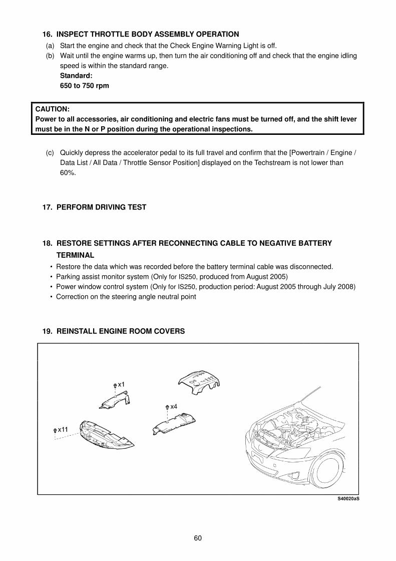
19. REINSTALL ENGINE ROOM COVERS