Embed Size (px)
Citation preview
BAO\060540004 (TMEVAL_PGE7_PGE_2-23-06.DOC) 1
T E C H N I C A L M E M O R A N D U M
Well Disposition Evaluation for Inactive Supply Well PGE-7PG&E Topock Compressor Station
DATE: February 23, 2006
IntroductionThis technical memorandum presents an evaluation of inactive water supply well PGE-07, as requested in the Department of Toxic Substances Control (DTSC) January 6, 2006 letter, Conditional Approval of the Draft Well Installation Work Plan for Interim Measures Performance Monitoring Program, dated November 30, 2005. In the January 6, 2006 letter, DTSC requests: (1) an evaluation of the potential vertical migration pathway from the Alluvial Aquifer to bedrock units enabled by the design of well PGE-07, and (2) a recommendation for reconstruction or decommissioning of the well. The letter also requests that a work plan be provided for either the reconstruction or decommissioning of PGE-07 (hereafter referred to as PGE-7).
Furthermore, the DTSC has verbally requested that an evaluation of the ambient groundwater velocity be performed in the PGE-7 borehole. This evaluation will take place prior to reconstruction, because the results may alter the final design of the preferred reconstruction method.
This memorandum reviews the well conditions and groundwater monitoring and hydraulic data for PGE-7 and nearby wells, describes a proposed measure for sealing the PGE-7 well/borehole, reviews methods for evaluating borehole velocity and well reconstruction, and provides recommendations.
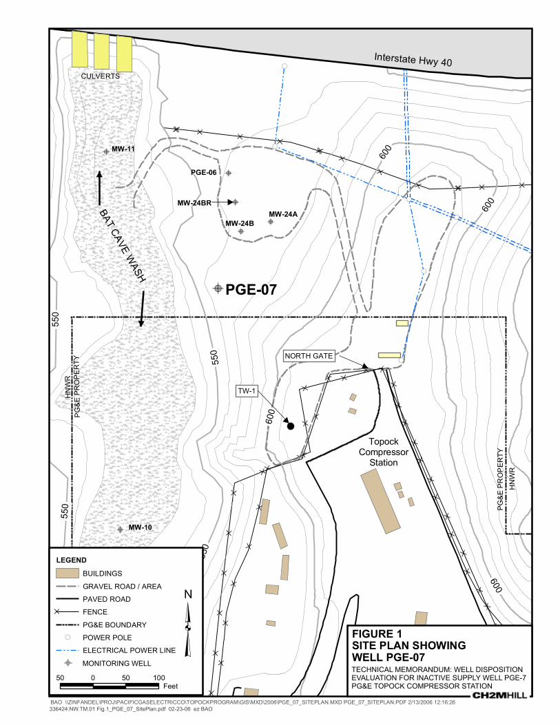
PGE-7 Well Construction Details Well PGE-7 is located approximately 250 feet northwest of the north gate to the Topock Compressor Station in an area known as the MW-24 bench (Figure 1). PGE-7 was originally installed in 1964, to a depth of 182 feet below ground surface (bgs), as a replacement water supply well for the Topock Compressor Station. The original well was constructed with 14-inch steel casing, with perforations from 110 feet to 180 feet bgs. In 1969, the well was deepened to 330 feet bgs, with a 7-inch-diameter blank steel liner installed to 195 feet bgs, and the remainder of the hole uncased to 330 feet bgs. Figure 2 is a schematic well completion diagram that summarizes the original well construction details and observations from a video log recorded by PG&E’s contractor in 1998. Table 1 summarizes well construction information for PGE-7 and other nearby wells PGE-6, MW-24A, MW-24B, and MW-24BR.
WELL PGE-7 RECONSTRUCTION/DECOMMISSIONING EVALUATION PG&E TOPOCK COMPRESSOR STATION
BAO\060540004 (TMEVAL_PGE7_PGE_2-23-06.DOC) 2
The depth of the contact of the Alluvial Aquifer with the Miocene conglomerate (bedrock) at the PGE-7 location is estimated at 220 feet bgs. Therefore, approximately 25 feet of the open-hole portion of PGE-7 is exposed to the base of the Alluvial Aquifer (Figure 2).
A geologic log for the drilling and deepening of PGE-7 is not available in PG&E’s records to provide lithologic description of the bedrock formation in this well. However, the 1998 video log indicates that angular rock with possible fractures is visible in the open borehole from 234 feet bgs to the top of the slough presently encountered in the well at 303 feet bgs. Based on logs from nearby borings (MW-24BR and TW-1), the bedrock formation present in PGE-7 is believed to be consolidated/cemented Miocene conglomerate. The lower portion of the deepened PGE-7 borehole may have also encountered the pre-Tertiary metadiorite bedrock that was logged in the former injection well PGE-8 (located approximately 750 feet south of PGE-7).
Groundwater Monitoring Results A review of hexavalent chromium (Cr[VI]) data from PGE-7 and the nearby MW-24 well cluster (Table 2) indicates that Cr(VI) concentrations in groundwater samples collected from Alluvial Aquifer monitoring wells MW-24A and MW-24B (averaging approximately 3,000 and 5,000 micrograms per liter [ g/L], respectively in 2001-2005 sampling) are similar to concentrations observed in the PGE-7 water samples (averaging approximately 4,900 g/Lin 2000-2003 sampling). Groundwater samples collected from monitoring well MW-24BR, screened within the bedrock formations, have been non-detect for Cr(VI) for six years of monitoring (except for one event immediately following well installation, which was probably an artifact of the drilling process). The similarity in groundwater sample results between PGE-7 and MW-24B, and the absence of Cr(VI) in MW-24BR, indicate that the Cr(VI) detected in PGE-7 samples is likely from that portion of the well that is completed across the base of the Alluvial Aquifer—and not from the bedrock units.
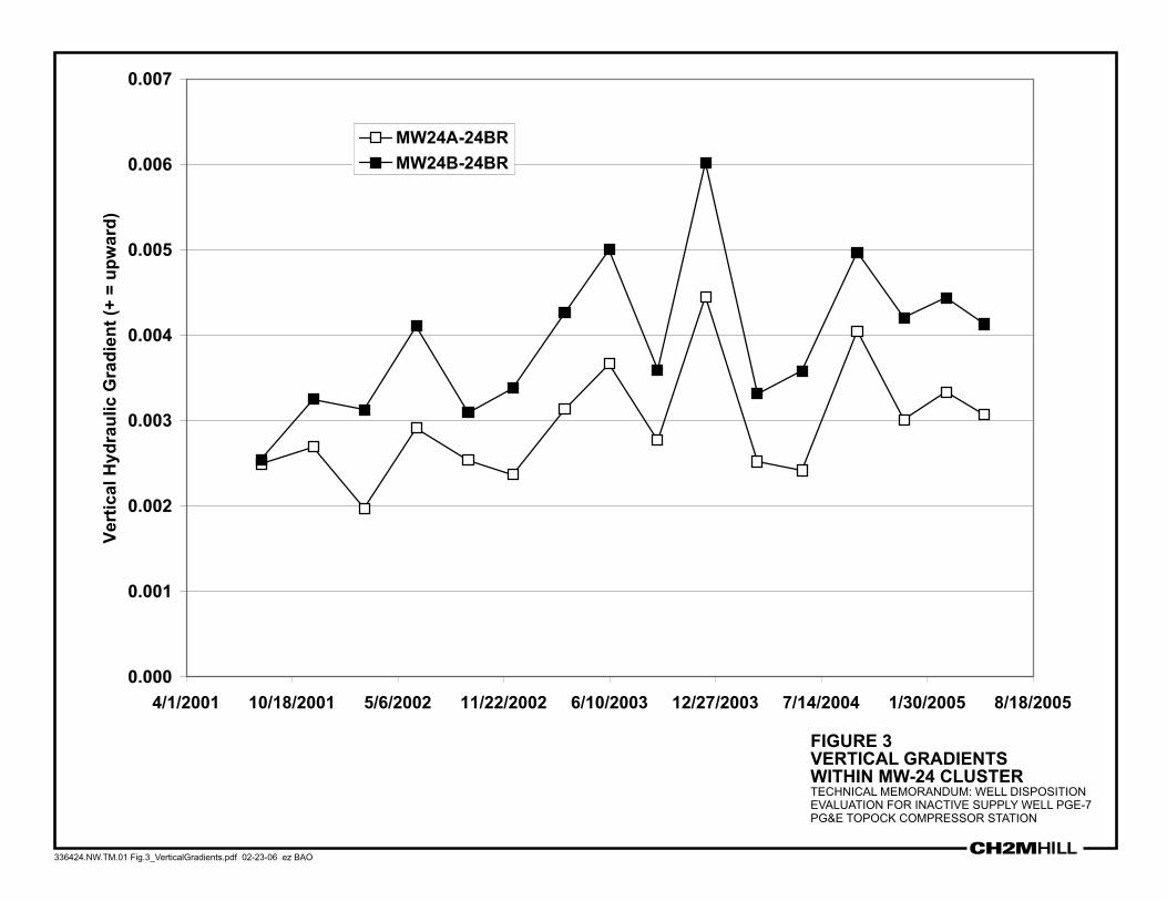
Summary of Vertical Gradients Water level data from monitoring wells in the PGE-7 area indicate that a persistent upward hydraulic gradient exists between the saturated zone in the bedrock and the Alluvial Aquifer. As summarized in Table 3, the bedrock monitoring well MW-24BR consistently records a higher ground water level (corrected for salinity and temperature) than MW-24A and MW-24B. The measured upward hydraulic gradients between MW-24BR and MW-24A & B range from 0.002 to 0.006 feet per foot (Table 3). The observed vertical gradients at the MW-24 cluster are fairly consistent in magnitude over four years of monitoring, and are always upward (Figure 3). This hydraulic condition reduces the potential for downward migration of groundwater from the Alluvial Aquifer to the bedrock formations.
Water levels in other well clusters located across the site at MW-20, MW-32, MW-33, and MW-34 typically display upward hydraulic gradients up to an order of magnitude greater than the horizontal gradients, although none of these other well clusters include wells completed in bedrock (CH2M HILL 2005).
WELL PGE-7 RECONSTRUCTION/DECOMMISSIONING EVALUATION PG&E TOPOCK COMPRESSOR STATION
BAO\060540004 (TMEVAL_PGE7_PGE_2-23-06.DOC) 3
Potential for Vertical Migration Despite the consistent upward hydraulic gradients, the influx of groundwater from bedrock to alluvium is not expected to be large because of the lower permeability of the bedrock with respect to the alluvium (e.g., well MW-24BR typically purges dry at one casing volume). As noted above, Cr(VI) concentrations have been very similar (range: 4,300 to 5,600
g/L) in the lower alluvial well MW-24B and in PGE-7, and non-detect in bedrock well MW-24BR (in all samples collected since 1998). While hydraulic gradients are upward from the bedrock to the alluvium at PGE-7, the Cr(VI) concentrations in groundwater samples collected from the present PGE-7 well completion are likely dominated by the contribution from the basal Alluvial Aquifer, and minimally affected by bedrock water quality because of permeability differences.
The potential for downward vertical migration at well PGE-7 is very low. With upward hydraulic gradients, Cr(VI) is not able to move downward into the bedrock. In addition, the apparent low permeability of the bedrock formation would not allow Cr(VI) present within the open borehole to move a significant distance away from the well.
However, the use of PGE-7 in its present condition for groundwater level or groundwater quality monitoring is problematic. As the well is completed as an open hole across the basal Alluvial Aquifer and the bedrock, the static water level is influenced by both zones. As previously mentioned, the water quality in the well is likely dominated by the more permeable Alluvial Aquifer. Although the vertical hydraulic gradients suggest that migration between the alluvium and the bedrock is unlikely to occur, it would be desirable to eliminate any potential for this in the unlikely event that the direction of vertical flow changes in the future.
Considerations for Temporary Sealing of PGE-7PGE-7 is one of only four wells that are screened in the bedrock unit at the Topock site (along with MW-24BR, MW-23, and PGE-8). An evaluation of published literature regarding the potential existence of pathways for chromium transport through bedrock is currently underway. The results of this evaluation will be used to determine the need for any future bedrock investigations at the Topock site. If further bedrock investigation is needed, well PGE-7 would be a viable candidate for reconstruction as a bedrock monitoring well. Until the need for and objectives of a bedrock investigation are more clearly identified, it is not obvious how this well should be reconstructed. Three different reconstruction options have been identified, each with advantages and disadvantages. The decision on whether PGE-7 would be used primarily for monitoring water levels or for monitoring water quality will influence the choice of reconstruction methods.
In the interim, a method by which PGE-7 could be temporarily sealed has been identified, which would eliminate any concern about the potential for cross-connection between alluvium and bedrock at this well. This method involves the installation of a flexible membrane liner manufactured by Flexible Liner Underground Technologies, LLC (FLUTe). The description and schematic of the FLUTe™ system presented below are from the company’s web site (http://flut.com/meth_1.htm).
WELL PGE-7 RECONSTRUCTION/DECOMMISSIONING EVALUATION PG&E TOPOCK COMPRESSOR STATION
BAO\060540004 (TMEVAL_PGE7_PGE_2-23-06.DOC) 4
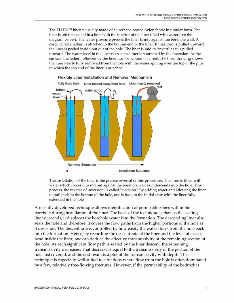
The FLUTe™ liner is usually made of a urethane coated nylon fabric in tubular form. The liner is often installed in a hole with the interior of the liner filled with water (see the diagram below). The water pressure presses the liner firmly against the borehole wall. A cord, called a tether, is attached to the bottom end of the liner. If that cord is pulled upward, the liner is peeled inside-out out of the hole. The liner is said to "invert" as it is pulled upward. The water level in the liner rises as the liner is shortened by the inversion. At the surface, the tether, followed by the liner, can be wound on a reel. The third drawing shows the liner nearly fully removed from the hole with the water spilling over the top of the pipe to which the top end of the liner is attached.
The installation of the liner is the precise reversal of this procedure. The liner is filled with water which forces it to roll out against the borehole wall as it descends into the hole. This process, the reverse of inversion, is called "eversion." By adding water and allowing the liner to pull itself to the bottom of the hole, one is back to the initial state with the liner fully extended in the hole.
A recently developed technique allows identification of permeable zones within the borehole during installation of the liner. The basis of the technique is that, as the sealing liner descends, it displaces the borehole water into the formation. The descending liner also seals the hole and therefore, it covers the flow paths from the higher portions of the hole as it descends. The descent rate is controlled by how easily the water flows from the hole back into the formation. Hence, by recording the descent rate of the liner and the level of excess head inside the liner, one can deduce the effective transmissivity of the remaining section of the hole. As each significant flow path is sealed by the liner descent, the remaining transmissivity decreases. That decrease is equal to the transmissivity of the portion of the hole just covered, and the end result is a plot of the transmissivity with depth. This technique is especially well suited to situations where flow from the hole is often dominated by a few, relatively free-flowing fractures. However, if the permeability of the bedrock is
WELL PGE-7 RECONSTRUCTION/DECOMMISSIONING EVALUATION PG&E TOPOCK COMPRESSOR STATION
BAO\060540004 (TMEVAL_PGE7_PGE_2-23-06.DOC) 5
uniformly low, the everting liner technique may not be sensitive enough to identify very small changes in flow at each small fracture zone.
While the FLUTeTM system discussed here is designed to profile the hydraulic conductivity of the borehole and to provide a seal against vertical flow, the FLUTeTM system can be modified at some future date to allow for the collection of water quality samples from multiple depths in the borehole. If it is determined that PGE-7 is no longer needed, the FLUTeTM liner could be removed and the borehole permanently abandoned using conventional well abandonment techniques, such as pressure grouting. Although leakage of the liner has not been a problem for FLUTe™ users (up to ten years use in wells with no leakage), monitoring of water levels inside the liner provides a simple way to monitor liner integrity.
Reconstruction Options Once the need for and objectives of a bedrock investigation have been identified, there are several methods that could be used to reconstruct PGE-7 to provide for monitoring of groundwater levels and quality. With proper reconstruction, PGE-7 will provide a valuable bedrock monitoring point while being protective of bedrock water quality. Three methods of reconstruction are discussed below, along with the advantages and disadvantages of each. Since there are distinct differences between the methods, PG&E recommends that the additional data that will be provided by the borehole flow logging (described below) and the FLUTeTM hydraulic conductivity profiling (described above) be reviewed before any decision is made on the best method for reconstruction of the well.
Three options for reconstructing PGE-7 as a bedrock monitoring well were evaluated:
1. Installation of a standard 2-inch diameter PVC monitoring well within the existing open borehole
2. Installation of Barcad samplers or nested 1-inch diameter mini-wells to provide multi-level sampling ports within the existing open borehole
3. Installation of the Water FLUTe™ liner equipped with multilevel sampling ports
Installing a 2-inch PVC monitoring well inside the existing borehole would use conventional techniques of filter pack and grout emplacement, via tremmie pipe. The well would be screened completely within the bedrock interval, potentially with a 60-foot screened interval (similar to bedrock well MW-24BR) from 240 to 300 feet bgs, or a longer well screen. A cement-bentonite grout seal would be placed above the filter pack, across the exposed bedrock/alluvium contact and up to the surface. This method would be performed using standard operating procedures, all of which have a proven track record.
Installation of nested wells within the existing casing and borehole would be similar in technique to the installation of a single 2-inch well, except the well casings would be of smaller diameter. Centralizers would be used to maintain the necessary open space between pipe and casing/borehole for grout emplacement. Besst Inc. manufactures a line of equipment known as Barcad samplers that can be installed in existing wells (http://www.besstinc.com/barcad_pumps.html). They have also recently developed a line of 1-inch diameter mini-wells, several of which could be installed inside the open borehole
WELL PGE-7 RECONSTRUCTION/DECOMMISSIONING EVALUATION PG&E TOPOCK COMPRESSOR STATION
BAO\060540004 (TMEVAL_PGE7_PGE_2-23-06.DOC) 6
of PGE-7 to provide multilevel monitoring. Mini-wells can be used to obtain water level and quality information.
As with the FLUTe™ liner described above, the Water FLUTe™ system allows for the sealing of a borehole, but includes tubes and ports for water quality sampling and hydraulic head measurements. The tubes and ports are added to the liner at the factory at the desired depths, and spacers can be installed around the ports to increase the area of sample collection if needed. Pressure transducers can be installed in-line with the sample tubes, and slender electronic water level meters can measure hydraulic heads of up to 150 ft in the 0.5-inch tubes. Each sample tube runs from the port to a central U-shaped tube and then to the surface. A check valve ensures that water can only flow from the sample tube to the U-tube. Samples are taken by applying pressurized gas to one side of the U-tube, forcing the water up and out the other side. When the pressure is reduced, the U-tube is refilled with water from the port. Each port has a dedicated sample tube and U-tube, so no water is shared between sampling depths. Since the opening of the sample tube is in direct contact with the geologic formation, only the sample tube needs to be purged, and purge volumes are dramatically reduced (i.e., 200 feet of 0.5-inch tubing = 2 gallon volume). More information is available at http://www.flut.com/meth_2.htm.
Table 4 provides a summary of advantages and disadvantages to these well reconstruction techniques. The ultimate choice for reconstruction will depend on the results of the vertical groundwater velocity evaluation (described below) and the vertical hydraulic conductivity profiling via the FLUTe™ system.
Evaluation of Vertical Groundwater Velocity in the Borehole Prior to installation of a temporary liner in PGE-7 as an interim sealing measure, an evaluation of natural flow within the borehole should be performed. We propose to measure flow at the uppermost section of the bedrock. This will provide an indication of the natural hydraulic gradients in the well, and the relative contributions of flow from bedrock and alluvial sections of the borehole when pumping.
Several flow metering methods were considered, including electromagnetic (EM), FloVision™, heat pulse, and impeller or spinner logging. A summary of this evaluation is presented below.
Electromagnetic flow monitoring relies on the principle that water flowing through a magnetic field will induce an electric current (Young et al. 1998). The current is measured, and is proportional to the strength of the magnetic field (a constant) and the velocity of the moving water. The technique is steady state, can measure very low (0.1 ft/min) and very high velocities, and works comparatively better than other techniques with high salinity waters, such as those found at PGE-7.
FloVision™ monitoring is a visual technique that relies on a down-hole video camera and analysis of particles moving past the camera lens. By having a visual log of the down-hole environment, questions regarding uncertainties such as seal integrity, interference from debris, and casing or borehole wall condition can be immediately answered. While the technique is reportedly able to quantify flows as low as 0.2 ft/min, it does not work well to measure high velocities.
WELL PGE-7 RECONSTRUCTION/DECOMMISSIONING EVALUATION PG&E TOPOCK COMPRESSOR STATION
BAO\060540004 (TMEVAL_PGE7_PGE_2-23-06.DOC) 7
Heat pulse probes use heat as a tracer; a heat source heats a small volume of water, and heat-sensors above and below record the movement of the heated water. The technique is capable of quantifying very low velocities (to 0.2 ft/min), but the thermal regime of the heated water is subject to disturbance from falling debris and subtle equipment movements, which can result in erratic results. Measurement of high flows is problematic.
The impeller technique relies on water movement to rotate an impeller. Despite construction with precision, low-friction bearings, a minimum flow of 3-4 ft/min is needed to generate impeller movement. This technique does work well with higher velocities generated during pumping. However, if very little water is coming from bedrock, it might not be sensitive enough to quantify this flow even under pumping conditions.
Table 5 provides a summary of the advantages and disadvantages of these techniques. Each technique would require the removal of the existing pump and hardware in the PGE-7 well. All methods require a flange or packer to seal the borehole around the instrument during velocity evaluation. Examination of the borehole video log suggests an irregularly shaped borehole (due to degradation of the borehole wall and accretion within the steel casing), and thus evaluation of borehole diameter with a precision caliper is recommended prior to the velocity evaluation, regardless of preferred technique. It is also possible that the well casing will need to be cleaned to accommodate the flange sizes for sealing of the open hole.
RecommendationsPrior to any work on PGE-7, the 1998 video log should be further reviewed by the team selected to perform the work. A caliper log is recommended in order to determine, as precisely as possible, the diameter of both the encrusted casing and the open borehole.
An evaluation of borehole velocity under both static and pumping conditions is recommended using the EM flow meter technique. This technique has been proven to be robust, and has the advantage of being able to measure very low flow as well as higher flow that might be generated under extraction conditions. The video log should be reviewed by the technical team to determine whether encrustations in the well casing will impede the descent of the proper flange for open borehole sealing during velocity measurements, and must be removed.
A FLUTeTM liner is recommended to be installed to eliminate any possibility of cross-connection between the alluvium and bedrock formations. Attempts will be made during the installation of the FLUTeTM liner to measure the transmissivity of the bedrock. The installed product will seal the casing in the interim, and can be modified as described above to provide depth-discrete groundwater sampling from the bedrock saturated zone.
With proper reconstruction, PGE-7 could provide a valuable bedrock groundwater monitoring well while eliminating the potential for cross-connection between the Alluvial Aquifer and bedrock.

BAO\060540004 (TMEVAL_PGE7_PGE_2-23-06.DOC)
Tables
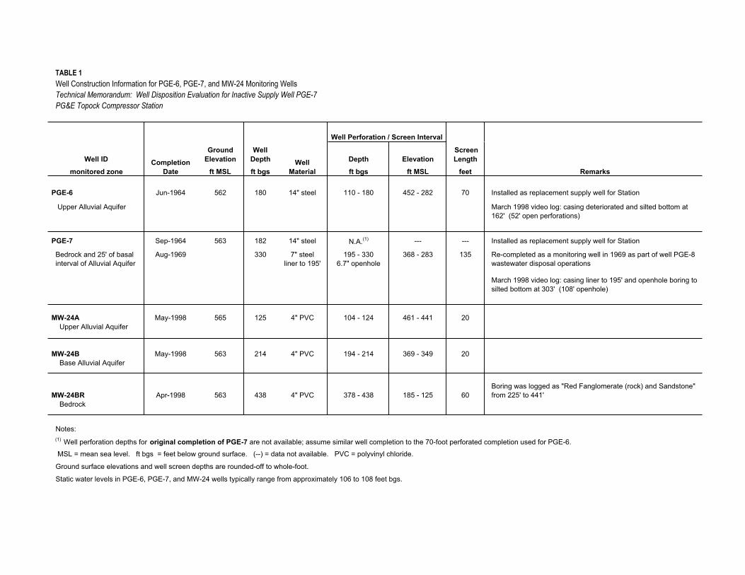
TABLE 1Well Construction Information for PGE-6, PGE-7, and MW-24 Monitoring WellsTechnical Memorandum: Well Disposition Evaluation for Inactive Supply Well PGE-7PG&E Topock Compressor Station
Well IDGround
ElevationWell
Depth Depth Elevation Screen Length
monitored zone ft MSL ft bgs ft bgs ft MSL feet
PGE-6 Jun-1964 562 180 14" steel 110 - 180 452 - 282 70 Installed as replacement supply well for Station
Upper Alluvial Aquifer March 1998 video log: casing deteriorated and silted bottom at 162' (52' open perforations)
PGE-7 Sep-1964 563 182 14" steel N.A.(1) --- --- Installed as replacement supply well for Station
Bedrock and 25' of basal interval of Alluvial Aquifer
Aug-1969 330 7" steel liner to 195'
195 - 3306.7" openhole
368 - 283 135 Re-completed as a monitoring well in 1969 as part of well PGE-8 wastewater disposal operations
March 1998 video log: casing liner to 195' and openhole boring to silted bottom at 303' (108' openhole)
MW-24A May-1998 565 125 4" PVC 104 - 124 461 - 441 20 Upper Alluvial Aquifer
MW-24B May-1998 563 214 4" PVC 194 - 214 369 - 349 20 Base Alluvial Aquifer
MW-24BR Apr-1998 563 438 4" PVC 378 - 438 185 - 125 60Boring was logged as "Red Fanglomerate (rock) and Sandstone" from 225' to 441'
Bedrock
Notes:(1) Well perforation depths for original completion of PGE-7 are not available; assume similar well completion to the 70-foot perforated completion used for PGE-6.
MSL = mean sea level. ft bgs = feet below ground surface. (--) = data not available. PVC = polyvinyl chloride.
Ground surface elevations and well screen depths are rounded-off to whole-foot.
Static water levels in PGE-6, PGE-7, and MW-24 wells typically range from approximately 106 to 108 feet bgs.
Well Perforation / Screen Interval
CompletionDate
WellMaterial Remarks
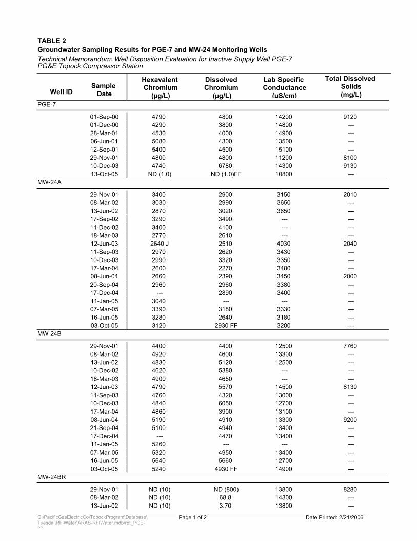
TABLE 2
PG&E Topock Compressor Station
Groundwater Sampling Results for PGE-7 and MW-24 Monitoring WellsTechnical Memorandum: Well Disposition Evaluation for Inactive Supply Well PGE-7
Well IDSample
Date
Hexavalent Chromium
(µg/L)
Dissolved Chromium
(µg/L)
Lab Specific Conductance
(µS/cm)
Total Dissolved Solids(mg/L)
PGE-7
01-Sep-00 4790 14200 9120 4800 01-Dec-00 4290 14800 ---3800 28-Mar-01 4530 14900 ---4000 06-Jun-01 5080 13500 ---4300 12-Sep-01 5400 15100 ---4500 29-Nov-01 4800 11200 8100 4800 10-Dec-03 4740 14300 9130 6780 13-Oct-05 ND (1.0) 10800 ---ND (1.0)FF
MW-24A
29-Nov-01 3400 3150 2010 2900 08-Mar-02 3030 3650 ---2990 13-Jun-02 2870 3650 ---3020 17-Sep-02 3290 --- ---3490 11-Dec-02 3400 --- ---4100 18-Mar-03 2770 --- ---2610 12-Jun-03 2640 J 4030 2040 2510 11-Sep-03 2970 3430 ---2620 10-Dec-03 2990 3350 ---3320 17-Mar-04 2600 3480 ---2270 08-Jun-04 2660 3450 2000 2390 20-Sep-04 2960 3380 ---2960 17-Dec-04 --- 3400 ---2890 11-Jan-05 3040 --- ------07-Mar-05 3390 3330 ---3180 16-Jun-05 3280 3180 ---2640 03-Oct-05 3120 3200 ---2930 FF
MW-24B
29-Nov-01 4400 12500 7760 4400 08-Mar-02 4920 13300 ---4600 13-Jun-02 4830 12500 ---5120 10-Dec-02 4620 --- ---5380 18-Mar-03 4900 --- ---4650 12-Jun-03 4790 14500 8130 5570 11-Sep-03 4760 13000 ---4320 10-Dec-03 4840 12700 ---6050 17-Mar-04 4860 13100 ---3900 08-Jun-04 5190 13300 9200 4910 21-Sep-04 5100 13400 ---4940 17-Dec-04 --- 13400 ---4470 11-Jan-05 5260 --- ------07-Mar-05 5320 13400 ---4950 16-Jun-05 5640 12700 ---5660 03-Oct-05 5240 14900 ---4930 FF
MW-24BR
29-Nov-01 ND (10) 13800 8280 ND (800)08-Mar-02 ND (10) 14300 ---68.8 13-Jun-02 ND (10) 13800 ---3.70
Page 1 of 2 Date Printed: 2/21/2006G:\PacificGasElectricCo\TopockProgram\Database\Tuesdai\RFIWater\ARAS-RFIWater.mdb\rpt_PGE-07
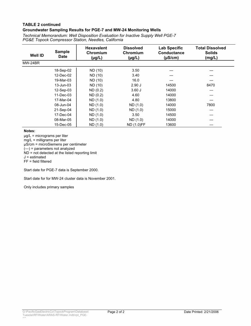
TABLE 2 continued
PG&E Topock Compressor Station, Needles, California
Groundwater Sampling Results for PGE-7 and MW-24 Monitoring WellsTechnical Memorandum: Well Disposition Evaluation for Inactive Supply Well PGE-7
Well IDSample
Date
Hexavalent Chromium
(µg/L)
Dissolved Chromium
(µg/L)
Lab Specific Conductance
(µS/cm)
Total Dissolved Solids(mg/L)
MW-24BR
18-Sep-02 ND (10) --- ---3.50 12-Dec-02 ND (10) --- ---3.40 19-Mar-03 ND (10) --- ---16.0 13-Jun-03 ND (10) 14500 8470 2.90 J12-Sep-03 ND (0.2) 14000 ---3.60 J11-Dec-03 ND (0.2) 14000 ---4.60 17-Mar-04 ND (1.0) 13800 ---4.80 08-Jun-04 ND (1.0) 14000 7800 ND (1.0)21-Sep-04 ND (1.0) 15000 ---ND (1.0)17-Dec-04 ND (1.0) 14500 ---3.50 08-Mar-05 ND (1.0) 14000 ---ND (1.0)15-Dec-05 ND (1.0) 13600 ---ND (1.0)FF
Notes:µg/L = micrograms per litermg/L = milligrams per literµS/cm = microSiemens per centimeter(---) = parameters not analyzedND = not detected at the listed reporting limitJ = estimatedFF = field filtered
Start date for PGE-7 data is September 2000.
Start date for for MW-24 cluster data is November 2001.
Only includes primary samples
Page 2 of 2 Date Printed: 2/21/2006G:\PacificGasElectricCo\TopockProgram\Database\Tuesdai\RFIWater\ARAS-RFIWater.mdb\rpt_PGE-07
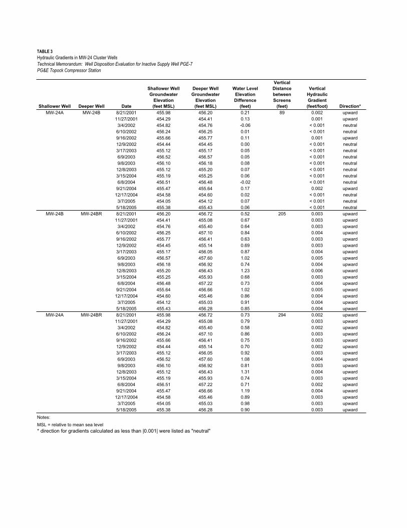
TABLE 3Hydraulic Gradients in MW-24 Cluster WellsTechnical Memorandum: Well Disposition Evaluation for Inactive Supply Well PGE-7PG&E Topock Compressor Station
Shallower Well Deeper Well Date
Shallower Well Groundwater
Elevation(feet MSL)
Deeper Well Groundwater
Elevation(feet MSL)
Water LevelElevationDifference
(feet)
VerticalDistancebetweenScreens
(feet)
VerticalHydraulicGradient(feet/foot) Direction*
MW-24A MW-24B 8/21/2001 455.98 456.20 0.21 89 0.002 upward11/27/2001 454.29 454.41 0.13 0.001 upward
3/4/2002 454.82 454.76 -0.06 < 0.001 neutral6/10/2002 456.24 456.25 0.01 < 0.001 neutral9/16/2002 455.66 455.77 0.11 0.001 upward12/9/2002 454.44 454.45 0.00 < 0.001 neutral3/17/2003 455.12 455.17 0.05 < 0.001 neutral6/9/2003 456.52 456.57 0.05 < 0.001 neutral9/8/2003 456.10 456.18 0.08 < 0.001 neutral
12/8/2003 455.12 455.20 0.07 < 0.001 neutral3/15/2004 455.19 455.25 0.06 < 0.001 neutral6/8/2004 456.51 456.48 -0.02 < 0.001 neutral
9/21/2004 455.47 455.64 0.17 0.002 upward12/17/2004 454.58 454.60 0.02 < 0.001 neutral
3/7/2005 454.05 454.12 0.07 < 0.001 neutral5/18/2005 455.38 455.43 0.06 < 0.001 neutral
MW-24B MW-24BR 8/21/2001 456.20 456.72 0.52 205 0.003 upward11/27/2001 454.41 455.08 0.67 0.003 upward
3/4/2002 454.76 455.40 0.64 0.003 upward6/10/2002 456.25 457.10 0.84 0.004 upward9/16/2002 455.77 456.41 0.63 0.003 upward12/9/2002 454.45 455.14 0.69 0.003 upward3/17/2003 455.17 456.05 0.87 0.004 upward6/9/2003 456.57 457.60 1.02 0.005 upward9/8/2003 456.18 456.92 0.74 0.004 upward
12/8/2003 455.20 456.43 1.23 0.006 upward3/15/2004 455.25 455.93 0.68 0.003 upward6/8/2004 456.48 457.22 0.73 0.004 upward
9/21/2004 455.64 456.66 1.02 0.005 upward12/17/2004 454.60 455.46 0.86 0.004 upward
3/7/2005 454.12 455.03 0.91 0.004 upward5/18/2005 455.43 456.28 0.85 0.004 upward
MW-24A MW-24BR 8/21/2001 455.98 456.72 0.73 294 0.002 upward11/27/2001 454.29 455.08 0.79 0.003 upward
3/4/2002 454.82 455.40 0.58 0.002 upward6/10/2002 456.24 457.10 0.86 0.003 upward9/16/2002 455.66 456.41 0.75 0.003 upward12/9/2002 454.44 455.14 0.70 0.002 upward3/17/2003 455.12 456.05 0.92 0.003 upward6/9/2003 456.52 457.60 1.08 0.004 upward9/8/2003 456.10 456.92 0.81 0.003 upward
12/8/2003 455.12 456.43 1.31 0.004 upward3/15/2004 455.19 455.93 0.74 0.003 upward6/8/2004 456.51 457.22 0.71 0.002 upward
9/21/2004 455.47 456.66 1.19 0.004 upward12/17/2004 454.58 455.46 0.89 0.003 upward
3/7/2005 454.05 455.03 0.98 0.003 upward5/18/2005 455.38 456.28 0.90 0.003 upward
Notes:MSL = relative to mean sea level* direction for gradients calculated as less than |0.001| were listed as "neutral"
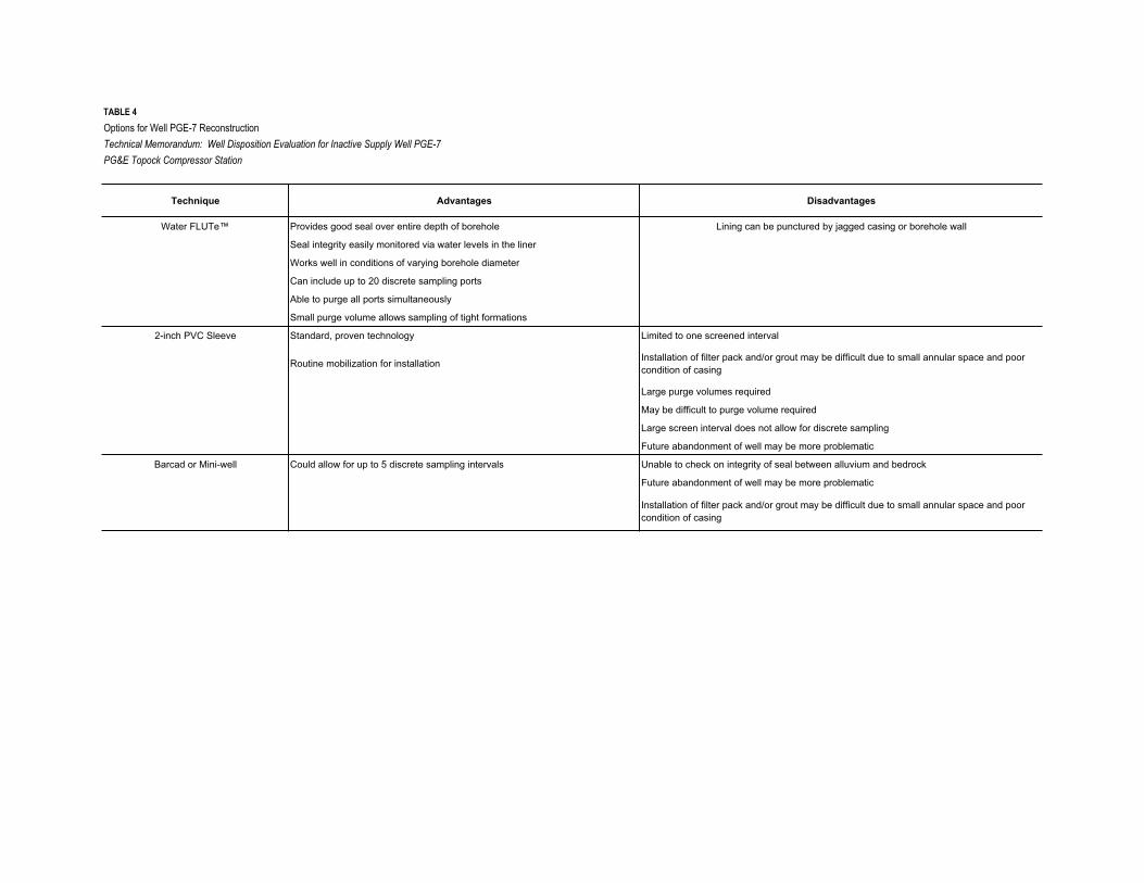
TABLE 4Options for Well PGE-7 Reconstruction
Technical Memorandum: Well Disposition Evaluation for Inactive Supply Well PGE-7
PG&E Topock Compressor Station
Technique Advantages Disadvantages
Water FLUTe™ Provides good seal over entire depth of borehole Lining can be punctured by jagged casing or borehole wall
Seal integrity easily monitored via water levels in the liner
Works well in conditions of varying borehole diameter
Can include up to 20 discrete sampling ports
Able to purge all ports simultaneously
Small purge volume allows sampling of tight formations
2-inch PVC Sleeve Standard, proven technology Limited to one screened interval
Routine mobilization for installation Installation of filter pack and/or grout may be difficult due to small annular space and poor condition of casing
Large purge volumes required
May be difficult to purge volume required
Large screen interval does not allow for discrete sampling
Future abandonment of well may be more problematic
Barcad or Mini-well Could allow for up to 5 discrete sampling intervals Unable to check on integrity of seal between alluvium and bedrock
Future abandonment of well may be more problematic
Installation of filter pack and/or grout may be difficult due to small annular space and poor condition of casing
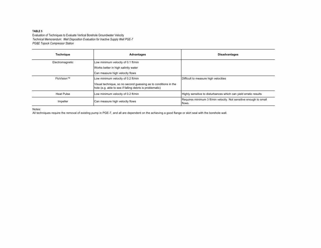
TABLE 5Evaluation of Techniques to Evaluate Vertical Borehole Groundwater VelocityTechnical Memorandum: Well Disposition Evaluation for Inactive Supply Well PGE-7PG&E Topock Compressor Station
Technique Advantages Disadvantages
Electromagnetic Low minimum velocity of 0.1 ft/min
Works better in high salinity water
Can measure high velocity flows
FloVision™ Low minimum velocity of 0.2 ft/min Difficult to measure high velocities
Visual technique, so no second guessing as to conditions in the hole (e.g. able to see if falling debris is problematic)
Heat Pulse Low minimum velocity of 0.2 ft/min Highly sensitive to disturbances which can yield erratic results
Impeller Can measure high velocity flows Requires minimum 3 ft/min velocity. Not sensitive enough to small flows.
Notes:All techniques require the removal of existing pump in PGE-7, and all are dependent on the achieving a good flange or skirt seal with the borehole wall.

BAO\060540004 (TMEVAL_PGE7_PGE_2-23-06.DOC)
Figures
55
5
55
5
5
5
5
5
55
5
5
5
5
5
5
55
5
5
55
55
5555
5
5
5
5
5
5
5
5
5
5
555
5
5
5
55
55
55
!A
!A
!A!A
!A
!A
!A!A
!(
!(
!(
!(
!(
!(
Interstate Hwy 40
MW-10
MW-24B
PGE-07
MW-24AMW-24BR
PGE-06
MW-11
600
600
600
550
600
550
550
550
BATCAVE
WASH
TopockCompressor
Station
HN
WR
PG
&E
PR
OP
ER
TY
HN
WR
PG
&E
PR
OP
ER
TY
NORTH GATE
CULVERTS
TW-1
50 0 50 100Feet
³ FIGURE 1SITE PLAN SHOWINGWELL PGE-07
LEGEND
BUILDINGS
GRAVEL ROAD / AREA
PAVED ROAD
5 FENCE
PG&E BOUNDARY
!( POWER POLE
ELECTRICAL POWER LINE
BAO \\ZINFANDEL\PROJ\PACIFICGASELECTRICCO\TOPOCKPROGRAM\GIS\MXD\2006\PGE_07_SITEPLAN.MXD PGE_07_SITEPLAN.PDF 2/13/2006 12:16:26
MONITORING WELLTECHNICAL MEMORANDUM: WELL DISPOSITION EVALUATION FOR INACTIVE SUPPLY WELL PGE-7PG&E TOPOCK COMPRESSOR STATION
336424.NW.TM.01 Fig.1_PGE_07_SitePlan.pdf 02-23-06 ez BAO
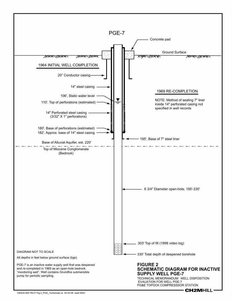
FIGURE 2SCHEMATIC DIAGRAM FOR INACTIVE SUPPLY WELL PGE-7TECHNICAL MEMORANDUM: WELL DISPOSITIONEVAUATION FOR WELL PGE-7PG&E TOPOCK COMPRESSSOR STATION
336424.NW.TM.01 Fig.2_PGE_7schematic.ai 02-20-06 dash BAO
Ground Surface
6 3/4" Diameter open-hole, 195'-330'
Base of Alluvial Aquifer, est. 220'
Concrete pad
1969 RE-COMPLETION
PGE-7
303' Top of fill (1998 video log)
All depths in feet below ground surface (bgs)
PGE-7 is an inactive water supply well that was deepenedand re-completed in 1969 as an open-hole bedrock“monitoring well”. Well contains Grundfos submersible pump for periodic sampling.
NOTE: Method of sealing 7" liner inside 14" perforated casing not specified in well records
DIAGRAM NOT TO SCALE
14" Perforated steel casing(3/32" X 1" perforations)
106', Static water level
14" steel casing
195', Base of 7" steel liner
182', Approx. base of 14" steel casing180', Base of perforations (estimated)
110', Top of perforations (estimated)
330' Total depth of deepened borehole
20” Conductor casing
Top of Miocene Conglomerate(Bedrock)
1964 INITIAL WELL COMPLETION
0.000
0.001
0.002
0.003
0.004
0.005
0.006
0.007
4/1/2001 10/18/2001 5/6/2002 11/22/2002 6/10/2003 12/27/2003 7/14/2004 1/30/2005 8/18/2005
Vert
ical
Hyd
raul
ic G
radi
ent (
+ =
upw
ard)
MW24A-24BRMW24B-24BR
FIGURE 3VERTICAL GRADIENTS WITHIN MW-24 CLUSTERTECHNICAL MEMORANDUM: WELL DISPOSITION EVALUATION FOR INACTIVE SUPPLY WELL PGE-7PG&E TOPOCK COMPRESSOR STATION
336424.NW.TM.01 Fig.3_VerticalGradients.pdf 02-23-06 ez BAO


![[DTSC] Alternatives Analysis Symposium II …dtsc.ca.gov/PollutionPrevention/.../Thompson_AAII-Presentation.pdf[DTSC] Alternatives Analysis Symposium II Chemical Compliance Systems,](https://img.pdfslide.net/doc/110x75/5ae656d97f8b9a08778cee1a/dtsc-alternatives-analysis-symposium-ii-dtsccagovpollutionpreventionthompsonaaii-.jpg)