Embed Size (px)
Citation preview
TECHNICAL STANDARD L2.
MEASURING AIR PERMEABILITY OF BUILDING ENVELOPES
(Non-Dwellings)
October 2010 Issue The Air Tightness Testing & Measurement Association c/o the British Institute of Non-Destructive Testing 1 Spencer Parade Northampton NN1 5AA Tel: +44 (0)1604 630124 Fax: +44 (0)1604 231489 web: www.attma.org www.bindt.org
Technical Standard L2 Issue 1 Page 2 of 32 30/09/10 www.attma.org
Content Page
Section 1- Introduction 3 1.1 Basis for measurement 3 1.2 Background 3 1.2.1 What is air leakage? 3 1.2.2 What is the impact of air leakage? 3 1.2.3 Why should we test? 4 1.3 Measuring Air Leakage 4 1.4 Fan Pressurisation Systems 5
Section 2 - Air Leakage Standards 6 2.1 Good and Best Practice Standards 6 2.2 Building Regulation Requirements Part L (England and Wales), Part F2 (Northern Ireland) or Section 6 of the Non-domestic Handbook (Scotland). 6
Section 3 - Specific Test and Building Preparation Procedure 8 3.1 Pre Test Requirements 8 3.2 Building Envelope Calculations 8 3.2.1 Air Permeability Area (m2) 9 3.2.2 Air Change Rate Volume (m3) 9 3.2.3 Envelope Area Calculation Example: Cold Roof Construction 10 3.2.4 Warm Roof Construction Example 11 3.3 Fan System Selection 11 3.4 Building Preparation 12 3.5 Further Test Equipment 13 3.6 Site Test Procedure 14 3.7 Test Results 16
Section 4 - Test Report 17
Section 5 - Large and Complex Non-Domestic Buildings 18 5.1 Permanently Compartmentalised Buildings 18 5.2 High Rise & Multi Storey Buildings 19 5.3 Large and Complex Buildings 20 5.3.1 Zone/Sample Testing 21 5.3.2 Building Extension Testing 21
Appendix A - Equations and Corrections 24 A.1.0 Equations 24 A.2.0 Essential parameters (r2 and n) 28 A.3.0 Limiting factors 29
Appendix B - Test Equipment Requirements 30 B.1.0 Introduction 30 B.2.0 Accuracy 30 B.3.0 Calibration 30
Appendix C - Equivalent Leakage Area (ELA) 32
Technical Standard L2 Issue 1 Page 3 of 32 30/09/10 www.attma.org
Section 1- Introduction
1.1 Basis for measurement
The requirements of ATTMA for the measurement of the air permeability of buildings are generally based on BS EN 13829:2001 - ‘Thermal Performance of Buildings - Determination of air permeability of buildings - Fan pressurisation method’ with enhancements recommended by ATTMA. This document provides the technical standard to be followed for the testing of Non-Dwellings as set out in Regulation 20B and Approved Document L2A 2010 of the Building Regulations for England and Wales, and Technical Booklet Part F2 in Northern Ireland, and Section 6 of the Non-Domestic Handbook in Scotland. For a testing organisation to show full compliance with this standard, they should have suitable third party monitoring systems in place. This is demonstrated by holding UKAS accreditation for building air leakage testing in line with ISO 17025:2005 and being registered with the BINDT in respect of air tightness testing. For guidance for test procedures for the testing of dwellings refer to ATTMA TSL1 available from www.attma.org.
1.2 Background
1.2.1 What is air leakage?
Air leakage is the uncontrolled flow of air through gaps and cracks in the fabric of a building (sometimes referred to as infiltration or draughts). This is not to be confused with ventilation, which is the controlled flow of air into and out of the building through purpose built ventilators that is required for the comfort and safety of the occupants. Too much air leakage leads to unnecessary heat loss and discomfort to the occupants from cold draughts. The increasing need for higher energy efficiency in buildings and the need in future to demonstrate compliance with more stringent Building Regulations targets means that airtightness has become a major performance issue. The aim should be to ‘Build tight – ventilate right’. Taking this approach means that buildings cannot be too airtight, however it is essential to ensure appropriate ventilation rates are achieved through purpose built ventilation openings.
1.2.2 What is the impact of air leakage?
Fabric heat losses have been driven down over many years by the various versions of the Building Regulations and there is limited return in reducing them down significantly further. The improvements made in the thermal performance of building materials have raised the importance of designing and constructing less leaky building envelopes. Airtightness of buildings was addressed for the first time in the 2002 edition of Part L of the Building Regulations (England and Wales). Although air pressure testing was only advised for non-domestic buildings greater then 1,000m². The 2006 revision of
Technical Standard L2 Issue 1 Page 4 of 32 30/09/10 www.attma.org
the Part L Regulations (England and Wales) or Part F (Northern Ireland) now sets a requirement to pressure test most non-domestic buildings and a sample of domestic properties. The airtightness of the UK building stock has traditionally been proven to be poor, which leads not only to unnecessary ventilation heat loss but also to widespread occupant dissatisfaction.
1.2.3 Why should we test?
Gaps and cracks in the building fabric are often difficult to detect simply by visual inspection. Air leakage paths through the building fabric can be tortuous; gaps are often obscured by internal building finishes or external cladding. The only satisfactory way to show that the building fabric is reasonably airtight is to measure the leakiness of the building fabric as a whole. Air leakage is quantified as Air Permeability. This is the leakage of air (m3.h-1) in or out of the building, per square metre of building envelope at a reference pressure difference of 50 Pa (m3.h-1.m-2 @ 50 Pa) between the inside and outside of the building.
1.3 Measuring Air Leakage
Assessment of building envelope air leakage involves establishing a pressure differential across the envelope and measuring the air flow required to achieve that differential. This is normally achieved by utilising variable flow portable fans which are temporarily installed in a doorway, or other suitable external opening. HVAC plant is switched off and temporarily sealed prior to the test. Passive ventilation should also be temporarily sealed. All doors and windows on the exterior of the air test envelope are closed. The test fans are switched on and the flow through them increased until a building pressure of 50 – 100 Pa is achieved. The total air flow through the fan and the building pressure differential created between the inside and outside is recorded. The fan speed is then slowly adjusted to produce sequential steps of not more than 10 Pa building pressure differential, with the fan flow and pressure differential data recorded at each step. The recorded fan flow (Q) and building pressure differential (p) data allow a relationship to be established. This can be defined in terms of the power law equation:
Q =C (p) n 1
Where C and n are constants that relate to the specific building under test. The total air flow required to achieve the reference pressure differential of 50 Pa can then be calculated from the equation (see Appendix A). This airflow is then divided by the total building envelope area (AE) to provide the Air Permeability result in m3.h-1.m-2 @ 50Pa.
Technical Standard L2 Issue 1 Page 5 of 32 30/09/10 www.attma.org
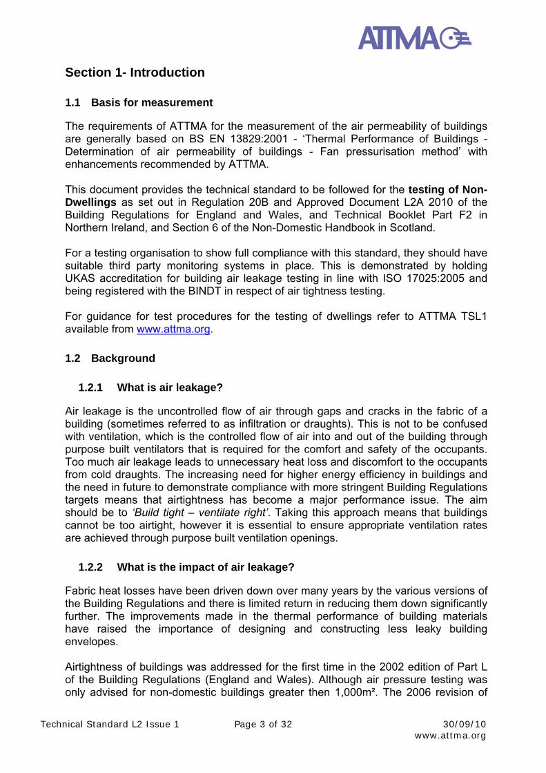
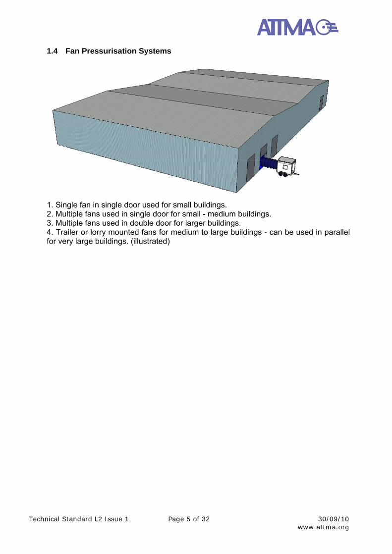
1.4 Fan Pressurisation Systems
1. Single fan in single door used for small buildings. 2. Multiple fans used in single door for small - medium buildings. 3. Multiple fans used in double door for larger buildings. 4. Trailer or lorry mounted fans for medium to large buildings - can be used in parallel for very large buildings. (illustrated)
Technical Standard L2 Issue 1 Page 6 of 32 30/09/10 www.attma.org
Section 2 - Air Leakage Standards
2.1 Good and Best Practice Standards
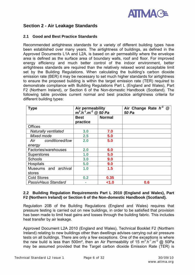
Recommended airtightness standards for a variety of different building types have been established over many years. The airtightness of buildings, as defined in the Approved Documents L1A and L2A, is based on air permeability where the envelope area is defined as the surface area of boundary walls, roof and floor. For improved energy efficiency and much better control of the indoor environment, better airtightness standards are required than the relatively relaxed worst acceptable limit set by the Building Regulations. When calculating the building’s carbon dioxide emission rate (BER) it may be necessary to set much higher standards for airtightness to ensure the proposed building is within the target emission rate (TER) required to demonstrate compliance with Building Regulations Part L (England and Wales), Part F2 (Northern Ireland), or Section 6 of the Non-domestic Handbook (Scotland). The following table provides current normal and best practice airtightness criteria for different building types:
Type Air permeability m3.h-1.m-2 @ 50 Pa
Air Change Rate h-1 @ 50 Pa
Best practice
Normal
Offices Naturally ventilated 3.0 7.0 Mixed mode 2.5 5.0 Air conditioned/low energy
2.0 5.0
Factories/warehouses 2.0 6.0 Superstores 1.0 5.0 Schools 3.0 9.0 Hospitals 5.0 9.0 Museums and archival stores
1.0 1.5
Cold Stores 0.2 0.35 PassivHaus Standard - <1.0 0.6
2.2 Building Regulation Requirements Part L 2010 (England and Wales), Part F2 (Northern Ireland) or Section 6 of the Non-domestic Handbook (Scotland).
Regulation 20B of the Building Regulations (England and Wales) requires that pressure testing is carried out on new buildings, in order to be satisfied that provision has been made to limit heat gains and losses through the building fabric. This includes heat transfer by air leakage. Approved Document L2A 2010 (England and Wales), Technical Booklet F2 (Northern Ireland) relating to new buildings other than dwellings advises carrying out air pressure tests on all buildings. There are only a few exceptions. One of the exceptions is where the new build is less than 500m², then an Air Permeability of 15 m3.h-1.m-2 @ 50Pa may be assumed provided that the Target carbon dioxide Emission Rate (TER) is
Technical Standard L2 Issue 1 Page 7 of 32 30/09/10 www.attma.org
achieved using the National Calculation Methodology. However, it may be desirable to pressure test since the actual (lower) air permeability can then be used to calculate the Building CO2 Emission Rate (BER). The other exception is where the building is extremely large or complex and this aspect is dealt with separately in Section 5 of this document. The general requirement for domestic and non-domestic buildings is for the building to be tested to comply with a maximum air permeability of 10 m3.h-1.m-2 at a test pressure differential of 50 Pa. However, in order to comply with the carbon emission target, a lower air permeability may be required by the Building Regulations and tested accordingly. The value for air permeability actually achieved will be used in the National Calculation Methodology (NCM) to assess the asset rating of the building as actually built. If the building fails to meet the carbon emission target, reducing and re-measuring the air permeability may be one of the few improvement factors practicable.
Technical Standard L2 Issue 1 Page 8 of 32 30/09/10 www.attma.org
Section 3 - Specific Test and Building Preparation Procedure
3.1 Pre Test Requirements
Liaison should be made with the client over the date and time of the test procedure. The client should be made fully aware of the nature of the test and the degree of disruption that it may cause to construction works and/or operation of the building. The test procedure can be significantly affected by extremes of weather (wind speed, internal/external temperatures). Weather forecasts should be checked prior to the proposed test date and if inclement weather is predicted, re-scheduling may be necessary. There may be occasions when the building needs to be tested in conditions that are less than ideal and under these circumstances this should be clearly identified in the test report. However, if tests need to be carried out during periods of ‘fresh’ (≥6 m/s) wind speeds, the zero flow pressures are likely to exceed ±5 Pa and thus result in an invalid test.
3.2 Building Envelope Calculations
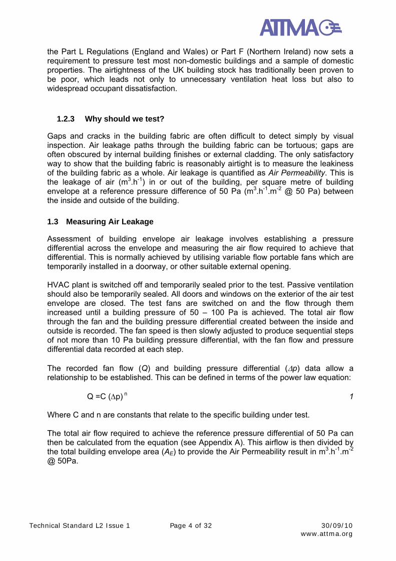
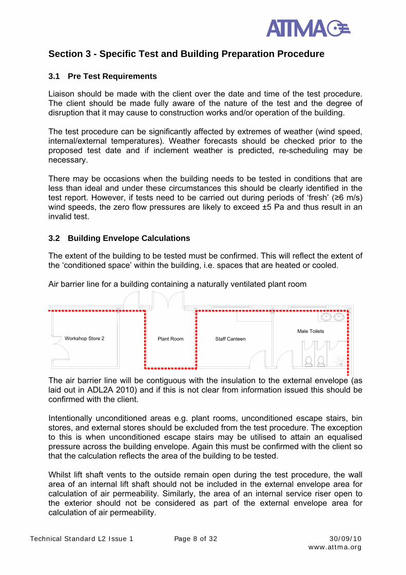
The extent of the building to be tested must be confirmed. This will reflect the extent of the ‘conditioned space’ within the building, i.e. spaces that are heated or cooled. Air barrier line for a building containing a naturally ventilated plant room
Workshop Store 2 Plant Room Staff Canteen
Male Toilets
The air barrier line will be contiguous with the insulation to the external envelope (as laid out in ADL2A 2010) and if this is not clear from information issued this should be confirmed with the client. Intentionally unconditioned areas e.g. plant rooms, unconditioned escape stairs, bin stores, and external stores should be excluded from the test procedure. The exception to this is when unconditioned escape stairs may be utilised to attain an equalised pressure across the building envelope. Again this must be confirmed with the client so that the calculation reflects the area of the building to be tested. Whilst lift shaft vents to the outside remain open during the test procedure, the wall area of an internal lift shaft should not be included in the external envelope area for calculation of air permeability. Similarly, the area of an internal service riser open to the exterior should not be considered as part of the external envelope area for calculation of air permeability.
Technical Standard L2 Issue 1 Page 9 of 32 30/09/10 www.attma.org
The area of the building envelope should be measured along the line of the component to be relied upon for air sealing. This will generally be the inner surface of the wall or roof assembly. Areas are measured as flat, i.e. no allowance is made for undulating profiles such as profiled cladding or textures to wall components. Similarly the surfaces within window and external door reveals are excluded. The calculated envelope area will be referred to in subsequent data analysis and test reports. This calculation should normally be undertaken by the testing organisation. The output from the calculation should be recorded and retained by the testing organisation, along with relevant drawings for future reference. An accurate evaluation of the building or test area envelope (AE) must be made prior to the test being undertaken. The necessary fan flow required to undertake a valid test should be calculated from this figure.
3.2.1 Air Permeability Area (m2)
For an Air Permeability envelope area (AE), all walls (including basement walls, if the basement is subject to test), roof and the floor are considered as part of the building envelope. For zone or sample testing the envelope area to be used to calculate the result should be that portion of the entire building envelope subject to the test, ie any internal to internal walls/ floors/ ceilings are not included. See section 5.3 for further guidance on multiple units within an overall building etc. This is the method of envelope measurement referred to in the Building Regulations Part L2A 2010 (England and Wales), Part F2 (Northern Ireland), and Section 6 of the Non-domestic Handbook (Scotland). Examples of envelope areas of a building are provided within Sections 3.2.3 and 3.2.4.
3.2.2 Air Change Rate Volume (m3)
The Air Change Rate volume (V) is the volume of air inside the building under test, for all the zones incorporated within the test zone, with no deductions for furniture. This is not required as standard, unless the specification requires an air change rate to be calculated (eg in the case of very airtight rooms within a building).
Technical Standard L2 Issue 1 Page 10 of 32 30/09/10 www.attma.org
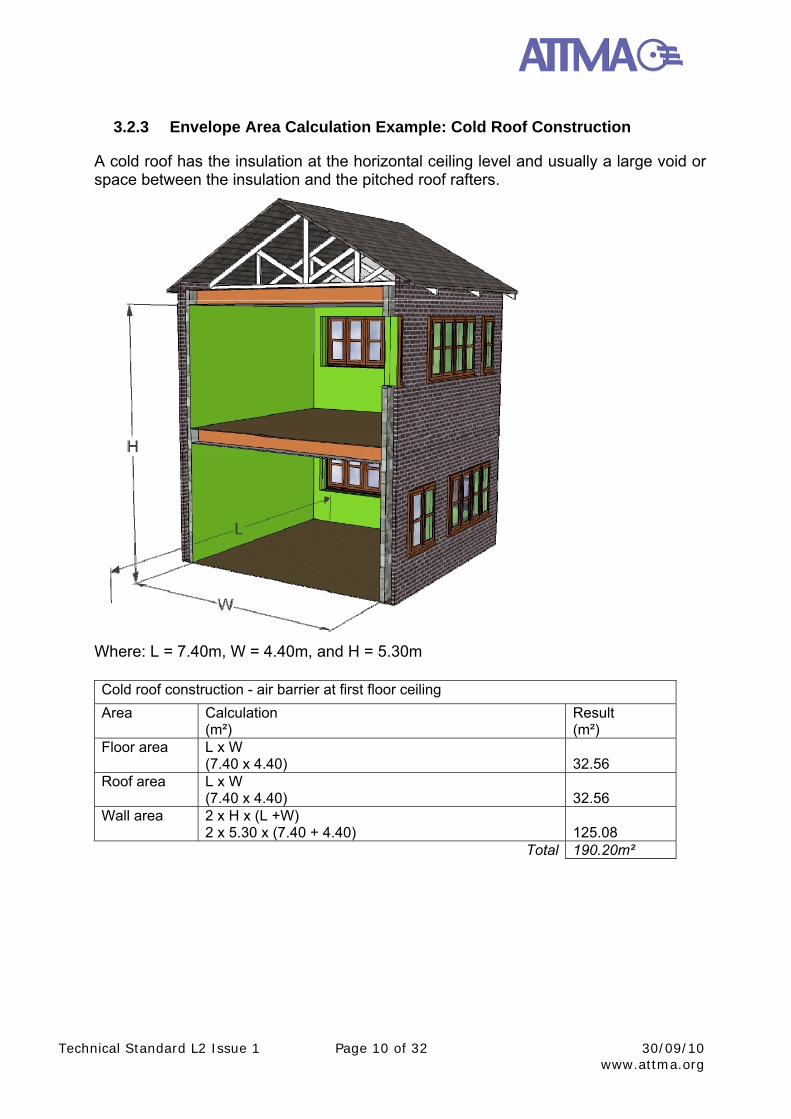
3.2.3 Envelope Area Calculation Example: Cold Roof Construction
A cold roof has the insulation at the horizontal ceiling level and usually a large void or space between the insulation and the pitched roof rafters.
Where: L = 7.40m, W = 4.40m, and H = 5.30m
Cold roof construction - air barrier at first floor ceiling
Area Calculation (m²)
Result (m²)
Floor area L x W (7.40 x 4.40)
32.56
Roof area L x W (7.40 x 4.40)
32.56
Wall area 2 x H x (L +W) 2 x 5.30 x (7.40 + 4.40)
125.08
Total 190.20m²
Technical Standard L2 Issue 1 Page 11 of 32 30/09/10 www.attma.org
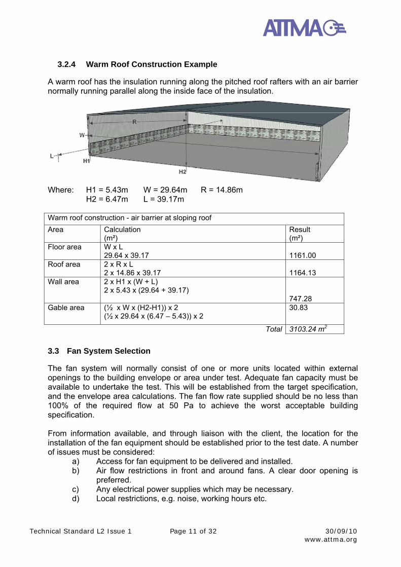
3.2.4 Warm Roof Construction Example
A warm roof has the insulation running along the pitched roof rafters with an air barrier normally running parallel along the inside face of the insulation.
Where: H1 = 5.43m W = 29.64m R = 14.86m H2 = 6.47m L = 39.17m Warm roof construction - air barrier at sloping roof
Area Calculation (m²)
Result (m²)
Floor area W x L 29.64 x 39.17
1161.00
Roof area 2 x R x L 2 x 14.86 x 39.17
1164.13
Wall area 2 x H1 x (W + L) 2 x 5.43 x (29.64 + 39.17)
747.28
Gable area (½ x W x (H2-H1)) x 2 (½ x 29.64 x (6.47 – 5.43)) x 2
30.83
Total 3103.24 m2
3.3 Fan System Selection
The fan system will normally consist of one or more units located within external openings to the building envelope or area under test. Adequate fan capacity must be available to undertake the test. This will be established from the target specification, and the envelope area calculations. The fan flow rate supplied should be no less than 100% of the required flow at 50 Pa to achieve the worst acceptable building specification. From information available, and through liaison with the client, the location for the installation of the fan equipment should be established prior to the test date. A number of issues must be considered:
a) Access for fan equipment to be delivered and installed. b) Air flow restrictions in front and around fans. A clear door opening is
preferred. c) Any electrical power supplies which may be necessary. d) Local restrictions, e.g. noise, working hours etc.
Technical Standard L2 Issue 1 Page 12 of 32 30/09/10 www.attma.org
e) Acceptable route for the air to flow from the fans and pressure to equalise throughout the test enclosure.
The last issue is important in certain larger structures where sizeable volumes of air will be pushed into the building during the test. Ideally air should enter the building along routes without restrictions or sharp turns. Air forced through narrow corridors or stairwells should be avoided if at all possible. If multiple fan systems are to be utilised, these should be located evenly around the building envelope whenever possible. This will allow a more even distribution of air around the test enclosure. The test can be undertaken either through pressurisation or depressurisation of the building envelope. This may be dictated by the specification, proposed test equipment, or by the practicalities of site conditions. Whichever method(s) are necessary, the nature of the test pressurisation should be confirmed prior to the test date. This may affect temporary sealing methods and locations. The fan system and associated equipment utilised must be calibrated in accordance with traceable standards, and must be within accepted calibration periods (see Appendix B).
3.4 Building Preparation
Prior to the test being undertaken, the building must be prepared to allow effective pressurisation, and representative results to be obtained. The method of preparation referred to in this document is generally compliant with BS EN 13829:2001 Method B – Test of the Building Envelope. To allow pressure to equalise fully around the test enclosure, all internal doors should be fully opened and restrained. All areas of the building to be tested should be connected by openings no smaller than a single leaf doorway (say 800mm x 2000mm); in many instances greater opening will be required to achieve uniform pressure. Any areas of the building where this is not achievable must be recorded and noted within the test report and may result in the test being invalid. Further guidelines for preparation include:
o Internal doors to riser cupboards may be closed but should not be artificially sealed.
o Lift doors should be closed (but not artificially sealed). Any external lift shaft vents should remain open.
o All drainage traps should be filled with water. o All incoming service penetrations (e.g. power, telecoms) should be
permanently sealed. o All external doors and windows should be closed (but not artificially
sealed). This includes door thresholds. The exception to this will be apertures to which test equipment is connected.
o Smoke vents should be closed but not artificially sealed. o Background trickle ventilators, passive ventilation systems and
permanently open uncontrolled natural ventilation openings should be temporarily sealed.
Technical Standard L2 Issue 1 Page 13 of 32 30/09/10 www.attma.org
o Mechanical ventilation and air conditioning systems should be turned off. These systems should be temporarily sealed to prevent air leakage through the systems during the test.
Should only part of a building be subjected to the test, then doors bounding the test enclosure which will ultimately not fall on the external envelope, may be temporarily sealed. For the result of the test to be representative, the external envelope should be in its final completed state. However it may be necessary to erect some temporary seals/screens to allow the test to be undertaken, (for example if a door or window has been broken, or is missing). Any such temporary seals must be robust enough to withstand the test pressure. Temporary seals employed during the test (including the method of closure of mechanical ventilation systems) must be spot checked and recorded for inclusion in the test report by the tester. It will normally be the responsibility of the client/main contractor to prepare the building prior to the test. It should be noted that temporary sealing to large and complex systems should not be under-estimated. Careful co-ordination and planning will be required to ensure all systems are adequately sealed. The testing organisation should undertake a reasonable assessment of the building envelope, both prior to and after the test being undertaken. Any elements at variance with these guide notes should be highlighted within the final report such that the client/building inspector may assess whether the result obtained is adequately representative of how the building would perform in its final completed condition. As temporary seals to unfinished works may, in practice, be more airtight than the envelope element that they replace, results obtained with such temporary seals should be qualified accordingly by the testing organisation.
3.5 Further Test Equipment
In addition to the fan pressurisation system, other pieces of equipment must be utilised during the test. The indoor/outdoor pressure difference is normally measured at the approximate geometric centre of the building or enclosure being tested. Measurements are normally obtained through small bore tubing (no greater than 6mm diameter). The internal reference tube will usually terminate near the geometric centre of the building. This must be located away from corridors or doorways where air movement (dynamic pressure) is likely to affect the readings obtained. Where the height of the building is less than 20 m the pressure differential tubing should be located near the geometric centre of the building. Where the height of the building is greater than 20 m the variation in building pressure differential should be checked to ensure this variation is less than +/- 10 %. Pressure differential tubing should be installed on the ground, top floor and geometric centre of the building. The pressure fans should be operated to provide approximately 50 Pa building pressure differential, but no lower than 45 Pa (higher pressures are acceptable). The building pressure differential at each location should be checked at each location. Providing the ground floor and top floor pressure measurements are within 10 % of the mid point location the test can proceed using the
Technical Standard L2 Issue 1 Page 14 of 32 30/09/10 www.attma.org
pressure measurement tube located on the mid floor. Where this value exceeds 10% measures should be taken to increase the open area between floors, and the building variation re-checked to ensure this variation is within 10%. Alternatively the test could proceed using the pressure measurement tube located furthest distance from the pressurisation fans, which will ensure the air leakage measured is a maximum. Pressure tubes should be kept away from locations where they may be trapped, or may become heated or cooled excessively. The external reference tube should be located away from the building envelope. This must terminate out of the air flows induced by the fan pressurisation system, and sheltered from any wind. Suitably calibrated pressure measuring devices shall be employed to measure the indoor/outdoor pressure difference. Suitably calibrated thermometers must be used inside and outside the building, to allow temperatures to be recorded before and after the test procedure. Where a variation in the internal or external air temperature is recorded during the test, an average shall be calculated. The location of all measurement devices/terminations must be recorded on site test data sheets. Measurement of barometric pressure is also necessary before and after the test.
3.6 Site Test Procedure
When the building has been suitably prepared, the test can commence. The client should be advised and asked to ensure that all external doors and windows remain closed for the duration. Whilst it is safe for the test to be undertaken with people remaining inside the building, it is often easier for the site operatives/staff to evacuate the building for the period of the test. It is prudent for the client to position a number of people around the building to ensure that doors and windows remain shut, and that any temporary seals employed remain intact for the duration of the test. Before the test commences, internal and external temperatures shall be recorded (Te1, Ti1). If the difference between these readings ΔT1, multiplied by the height of the tested building in metres is in excess of 250 m.C there is a significant risk that the zero flow pressure difference is likely to be excessive. All pressure measuring and flow measurement devices should be zeroed as necessary at this stage. With the opening(s) of the air moving equipment temporarily covered, the pressure measuring devices should be connected to the internal/external reference pressure tubes. The following zero flow pressure readings shall be recorded:
ΔP0,1+ The average of positive values recorded over a minimum of 30 seconds
Technical Standard L2 Issue 1 Page 15 of 32 30/09/10 www.attma.org
ΔP0,1- The average of negative values recorded over a minimum of 30 seconds
ΔP0,1 The average of all values recorded over a minimum of 30 seconds
If any of ΔP0,1+, ΔP0,1-, ΔP0,1 are is found to be in excess of ±5 Pa, conditions are not suitable to undertake a valid test, and the client should be advised. Wind speed and temperature may be the cause of excessive zero flow pressure differences, and waiting until the environmental conditions change may reduce the figure to an acceptable level. It should also be confirmed that mechanical ventilation systems are suitably isolated so as not to cause this effect. Once acceptable zero flow pressure difference readings have been taken, covers from the air moving equipment should be removed. Air pressurisation equipment can then be turned on to pressurise or depressurise the building/enclosure. The test is carried out by taking a series of measurements of air flow rates and corresponding indoor/outdoor pressure difference over a range of fan flows. Due to the instability of induced pressures at lower levels, the minimum pressure difference must be the greater of 10 Pa, or five times the zero flow pressure measured prior to the test (the greater of ΔP0,1+, ΔP0,1-). The highest pressure difference (corrected) must be greater than 50 Pa. If less than 50 Pa is achieved, the test is not valid and this must be recorded within the final test report along with the reason why. Readings taken at low pressures will be more adversely affected by environmental conditions and any conclusions drawn from such a report should be treated with caution. The test can be undertaken with the building envelope either positively or negatively pressurised, and results obtained in either situation are valid. Alternatively both positive and negative tests may be carried out, and an average of the results calculated. It is recommended that pressurisation systems are switched on in a controlled manner. Great care must be taken to ensure that the building does not become over pressurised (>100 Pa) as this may present a risk to internal finishes and the fabric of the building. Measurements must be taken at a minimum of 5 pressures between the maximum and minimum induced pressures, i.e. a minimum of 7 points, with intervals between pressures being no greater than 10 Pa. It is recommended that wherever possible 8 to 10 pressure differences are recorded. It is normally beneficial to take readings over a broad range of building pressures. (minimum of 25 Pa) Adequate time must be allowed for induced pressures to stabilise throughout the building envelope. This is particularly significant in larger high rise buildings, and where many internal walls/corridors subdivide the internal space.
Technical Standard L2 Issue 1 Page 16 of 32 30/09/10 www.attma.org
Once steady pressure (Δp) and flow (Q) readings are obtained, these shall be recorded. Where multiple fans are utilised, it must be ensured that flow measurement readings are taken for each fan. When a full set of data has been recorded, the pressurisation system should be switched off and the fan opening re-covered. The following should then be recorded:
ΔP0,2+ The average of positive values recorded over a minimum of 30 seconds
ΔP0,2- The average of negative values recorded over a minimum of 30 seconds
ΔP0,2 The average of all values recorded over a minimum of 30 seconds
If any of ΔP0,2+, ΔP0,2-, ΔP0,2 is found to be in excess of ± 5 Pa, the conditions have not been suitable to undertake a valid test, and the client should be advised. Should any test have been undertaken with zero flow pressure differences (either before or after the test) in excess of ± 5 Pa, then any result obtained must be qualified accordingly. Whilst the test undertaken may provide an approximate result, this should not be used to prove compliance with any specification. External and internal temperatures should be recorded (Te2, Ti2). Where necessary an average reading may be taken e.g. in high rise buildings. Following the test it should be confirmed that the building conditions have remained stable during the test, and that temporary seals and external doors have remained closed.
3.7 Test Results
The recorded test data must be analysed and corrected in accordance with the standard equations contained within Appendix A. The final test result is expressed as a rate of leakage per hour per square metre of building envelope at a reference pressure differential of 50 Pa (m3.h-1.m-2 @ 50 Pa). This is calculated by dividing the total calculated leakage flow rate Q50 by the envelope area AE.
Technical Standard L2 Issue 1 Page 17 of 32 30/09/10 www.attma.org
Section 4 - Test Report
The report shall contain at least the following information:
a) All details necessary to identify the building/envelope tested; purpose of test (method A or B) as per BS EN 13829:2001; post address and estimated date of construction of the building.
b) A reference to this standard and any deviation from it.
c) Test object: - description of which parts of the building were subject to the test; - envelope area; - documentation of test calculations so that the stated results can be
verified; - the general status of openings on the building envelope, latched, sealed,
open, etc.; - detailed description of temporarily sealed openings, if any; - the type of heating, ventilating and air conditioning system.
d) Apparatus and procedure: - equipment and technique employed.
e) Test data: - zero-flow pressure differences ∆P0,1+ , ∆P0,1- , ∆P0,2+ , ∆P0,2- , ∆P0,1 and
∆P0,2 for pressurization and depressurization test; - External and internal temperatures before and after the test; - barometric pressure before and after the test; - differential pressure on lowest and highest floor at highest flow rate
achieved if required; - table of induced pressure differences and corresponding air flow rates; - air leakage graph, with value of correlation coefficient r²; - the air flow coefficient Cenv , the air flow exponent, n, and the air leakage
coefficient CL, for both pressurization and depressurization tests determined by the method indicated;
- Air permeability result and test target
f) Date of test.
g) Name and address of organisation/individual carrying out the test and details of the credentials permitting them to do so (UKAS Accreditation number).
Technical Standard L2 Issue 1 Page 18 of 32 30/09/10 www.attma.org
Section 5 - Large and Complex Non-Domestic Buildings
There will be instances where it is not feasible or practicable to carry out an airtightness test on an entire building or complex. The following sections detail various approaches to overcome these difficulties.
5.1 Permanently Compartmentalised Buildings
It may be impractical to carry out whole building pressurisation tests on compartmentalised buildings which are divided into separate units having no internal openings to link them. In this case separate pressurisation tests should be carried out on each self contained compartment. Multiple Occupancy Buildings – Residential In some instances it may not be readily apparent how the building should be tested. The method of test should ultimately be confirmed with the BCB, however, it might also be dictated by the requirements of the SBEM and SAP calculations. The following provides a guide as to how such buildings might be considered. Student Halls – Halls of residence fall within the scope of ADL2A and might therefore be covered by the SBEM calculation. This calculation will specify the target air permeability specification and that the halls should be tested as a whole block (unless the building is deemed to fall within the criteria for Multi-storey or Large and Complex Buildings – refer to sections 5.2 and 5.3 below). In such circumstances this building will be treated as any other building tested for ADL2A purposes. Sheltered Housing – Some residential buildings such as sheltered housing provide independent living accommodation together with associated facilities such as communal areas and offices. There is usually no clear distinction between the areas with common rooms interspersed between the residential units. It is therefore difficult to ascertain exactly how these buildings should be tested since it is possible that the whole building could be subject to an SBEM calculation and each of the residential units (for sale or rent) a SAP calculation. The carbon emission calculations undertaken and therefore the testing regime required will need to be determined at the commencement of the project with the BCB. Where an SBEM calculation covers the whole building, then the air permeability test must be undertaken to test the whole of the building envelope. This will include testing into each of the residential units by opening the apartment doors. The results of such a test will be used to show compliance with the requirements of ADL2A. Where there is a further requirement for the residential units to comply with specific SAP calculations, then a representative sample of those also must be tested in accordance with the requirements of the Building Regulation Requirements Part L 2010 (England and Wales), Part F1 (Northern Ireland) or Section 6 of the domestic Handbook (Scotland). Apartments over Retail – Many buildings are now constructed with residential accommodation above ground floor retail units. In such instances there is typically a clearly defined boundary between the different types of use. The different types of use will usually be separated by a solid floor slab and be served by independent
Technical Standard L2 Issue 1 Page 19 of 32 30/09/10 www.attma.org
entrances. The retail units should be tested generally in accordance with this Technical Standard and the requirements ADL2A. Furthermore, a representative sample of the residential accommodation should be tested in accordance with the requirements of the Building Regulation Requirements Part L 2010 (England and Wales), Part F1 (Northern Ireland) or Section 6 of the domestic Handbook (Scotland).
5.2 High Rise & Multi Storey Buildings
It can be difficult to achieve equal pressure across a high rise building and so it may be necessary to employ multiple fans at different points within the building. Above fifteen storeys, the pressure loss up through the stairwells may become significant with respect to the requirement for all internal pressures to be within 10%, unless there are light wells and/or Atria - factors which would alleviate the testing situation. For buildings well above fifteen storeys, the lift shafts could be deployed by opening doors at various levels - provided suitable safety precautions are deployed. This normally provides sufficient open area up through the building for the building to be pressurised as a complete unit. If lift shafts cannot be deployed, due to safety or practical reasons, it may be possible to utilise riser shafts, if they have been horizontally airsealed at ground floor slab and top floor roof levels. For buildings above fifteen storeys it may be appropriate, under some circumstances, to test the building by floor level. A potential testing scenario is as follows:
Test the ground floor and pressurise the first floor simultaneously to produce the same test pressures on both of those floors. The flow rates to the ground floor should be recorded and analysed in the usual way but taking the envelope area as that of the ground floor slab and external wall area of the ground floor only. If the first floor plan area is less than the ground floor, then any ground floor roof areas may be included in to the envelope area.
Test a selected intermediate floor at the same time as pressuring the floors
above and below the test floor at the same test pressures. The data should be analysed in the usual way but the envelope area will be the area of the external walls of the test floor only.
Test the top floor and pressurise the floor below it and take the envelope area
as that of the external walls of the top floor and the roof area. Sufficient open area between the test floor and adjacent floors should be provided along with a route to feed the outside differential pressure tube. This aspect applies to all tests.
The number of intermediate floors tested should be taken as 10%, unless there
are substantially different methods of construction between floor levels.
If all of the above measured air leakage rates are less than the required specification then the building would have passed the air permeability criteria.
Technical Standard L2 Issue 1 Page 20 of 32 30/09/10 www.attma.org
If any of the building elements fail the required criteria then the Q50 for the ground floor plus the Q50 for the top floor should be summed with the highest Q50 for an intermediate floor multiplied by the number of the intermediate floors. This total air flow rate should then be divided by the envelope area of the building to produce a final value.
Most triple fan blower door systems will deliver a total of >6m³/s. An intermediate floor area of 4,000m² and a height between floors of 4 metres would require a flow rate of around 2.8m³/s per floor at an air permeability of 10m³/(h.m²). The top floor would potentially require two triple fan blower doors with one double fan blower door on the floor below. Ground floors very often have a footprint greater than the main high rise portion of the building, but then normal large portable fans can be used at this level. Most high-rise buildings could therefore be tested with this methodology, assuming that an adequate airseal is provided by riser shafts within the test zone. If the cross-sectional area changes dramatically after second floor level and above, extreme care and diligence should be applied to the testing methodology and air flow testing requirements. More floor levels may need to be tested under these circumstances.
5.3 Large and Complex Buildings
Large, in the context of this document, means buildings with an envelope area in excess of 80,000 m2 with a target air permeability of 10 m3.h-1.m-2 @ 50Pa or 160,000 m2 with a target air permeability of 5 m3.h-1.m-2 @50Pa. Complex and large buildings could encompass new District General Hospitals, Airport Terminals, Large City Shopping Centres and large developments where there is a phased hand-over spread over a significant time period. It is expected that many of these building types can be broken down by Department or groups of Retail Outlets, for instance, which could facilitate part pressure testing. Were separate retail units or commercial units within an overall building are to be tested the envelope will include all the boundary surfaces, ie the unit will be treated as an entirely independent entity for the purpose of the air test. (This would also apply to clean rooms, isolation rooms etc) There will no doubt be some, albeit few, buildings where none of the above approaches would be practicable and in such instances the following approach is recommended:
The Building Control Body should confirm that none of the above is practicable and that this is therefore to be treated as a ‘Special Case’.
The Building Control Body should approve the approach to ensure that the development will be constructed to the required airtightness standard (no less than 5 m3.h-1.m-2 @50Pa), taking due cognisance of air sealing details and component testing where necessary.
A thorough quality management procedure is required. An ATTMA member should oversee the project with regard to airtightness issues, inspect detailed air sealing drawings, inspect the building at intervals during construction, require robust QA site auditing procedures from main and package contractors, recommend full-scale mock-ups of sections of the building be tested and/or recommend air tightness testing of components.
Technical Standard L2 Issue 1 Page 21 of 32 30/09/10 www.attma.org
For the purpose of certification, inspections must be carried out at least monthly during formation of the building envelope, and for more complex buildings this must increase appropriately.
Detailed specifications and drawings with regard to air sealing must be collated and reviewed, particularly where different trade contractor ‘packages’ need to be air sealed to each other. Where there is likelihood that these sealing details can not be inspected progressively before such details become concealed, a system, such as photographic records, should be put in place so that there is comprehensive assurance that the building is built to the design criteria.
Contractor’s tradesmen should be given demonstrations of what the goals are and what to watch out for in their work to avoid defects.
Contractors may be required to remove items which conceal air sealing details for inspection.
Feedback from the results of mock-up or component testing should be implemented in the general design.
An audit trail should be kept and, at handover, be handed to the client for archiving. Where practically feasible sample areas should be tested in accordance with the requirements for phased handover.
5.3.1 Zone/Sample Testing
Phased handover or occupancy of a building may preclude the testing of a whole building in practical terms. If such situations exist, a test to a representative sample may be deemed reasonable. This should represent at least 20% of the building envelope area and the areas tested must be representative of the external envelope construction for the building as a whole. Where samples are used to prove compliance of larger areas of the building, it is necessary to achieve a test result 10% below the target specification, thereby giving some comfort that workmanship and detail issues elsewhere may not compromise the envelope air leakage performance when considered for the whole. When testing of sample areas is to be carried out it is important to consider internal walls or temporary screens isolating test zones that will also be tested. Leakage through these elements will impact upon the result for the sample in question, although ultimately they may not form part of the building envelope.
5.3.2 Building Extension Testing
Where the extension can be tested as a separate entity from the existing building, this will be relatively straightforward. However, in some cases it will not be practicable to test the extension separately, for example an extension to the sales floor of a large retail outlet. Under these circumstances one approach would be for the existing building, or part thereof, to be airtightness tested before extension works commence in order to characterise the performance of the existing building. On completion of the extension, the building or section of the building will require to be airtightness tested again. The air quantity required to pressurise the existing part of the building including the new extension minus the air quantity required to pressurise the existing part of the building, divided by the envelope area of the extension will provide the air permeability of the extension. An airtightness test on the original building should be carried out
Technical Standard L2 Issue 1 Page 22 of 32 30/09/10 www.attma.org
before planning approval is granted for the extension. An alternative approach would be to follow the procedures for a large complex building as described in Section 5 of this document.

Technical Standard L2 Issue 1 Page 23 of 32 30/09/10 www.attma.org
Appendices
Technical Standard L2 Issue 1 Page 24 of 32 30/09/10 www.attma.org
Appendix A - Equations and Corrections
A.1.0 Equations
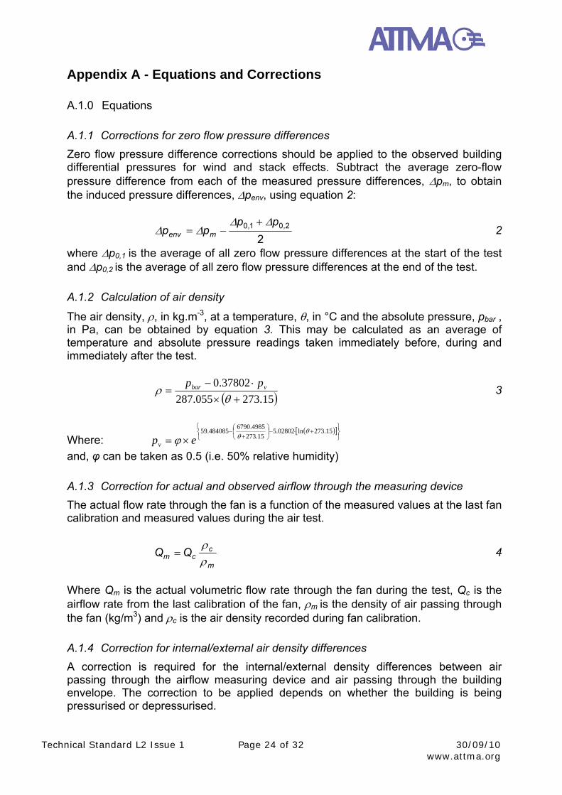
A.1.1 Corrections for zero flow pressure differences
Zero flow pressure difference corrections should be applied to the observed building differential pressures for wind and stack effects. Subtract the average zero-flow pressure difference from each of the measured pressure differences, pm, to obtain the induced pressure differences, penv, using equation 2:
22010 ,,
menv
pppp
2
where p0,1 is the average of all zero flow pressure differences at the start of the test and p0,2 is the average of all zero flow pressure differences at the end of the test.
A.1.2 Calculation of air density
The air density, , in kg.m-3, at a temperature, , in °C and the absolute pressure, pbar , in Pa, can be obtained by equation 3. This may be calculated as an average of temperature and absolute pressure readings taken immediately before, during and immediately after the test.
15.273055.287
37802.0
vbar pp 3
Where:
15.273ln02802.5
15.273
4985.6790484085.59
epv
and, φ can be taken as 0.5 (i.e. 50% relative humidity)
A.1.3 Correction for actual and observed airflow through the measuring device
The actual flow rate through the fan is a function of the measured values at the last fan calibration and measured values during the air test.
m
ccm QQ
4
Where Qm is the actual volumetric flow rate through the fan during the test, Qc is the airflow rate from the last calibration of the fan, m is the density of air passing through the fan (kg/m3) and c is the air density recorded during fan calibration.
A.1.4 Correction for internal/external air density differences
A correction is required for the internal/external density differences between air passing through the airflow measuring device and air passing through the building envelope. The correction to be applied depends on whether the building is being pressurised or depressurised.
Technical Standard L2 Issue 1 Page 25 of 32 30/09/10 www.attma.org
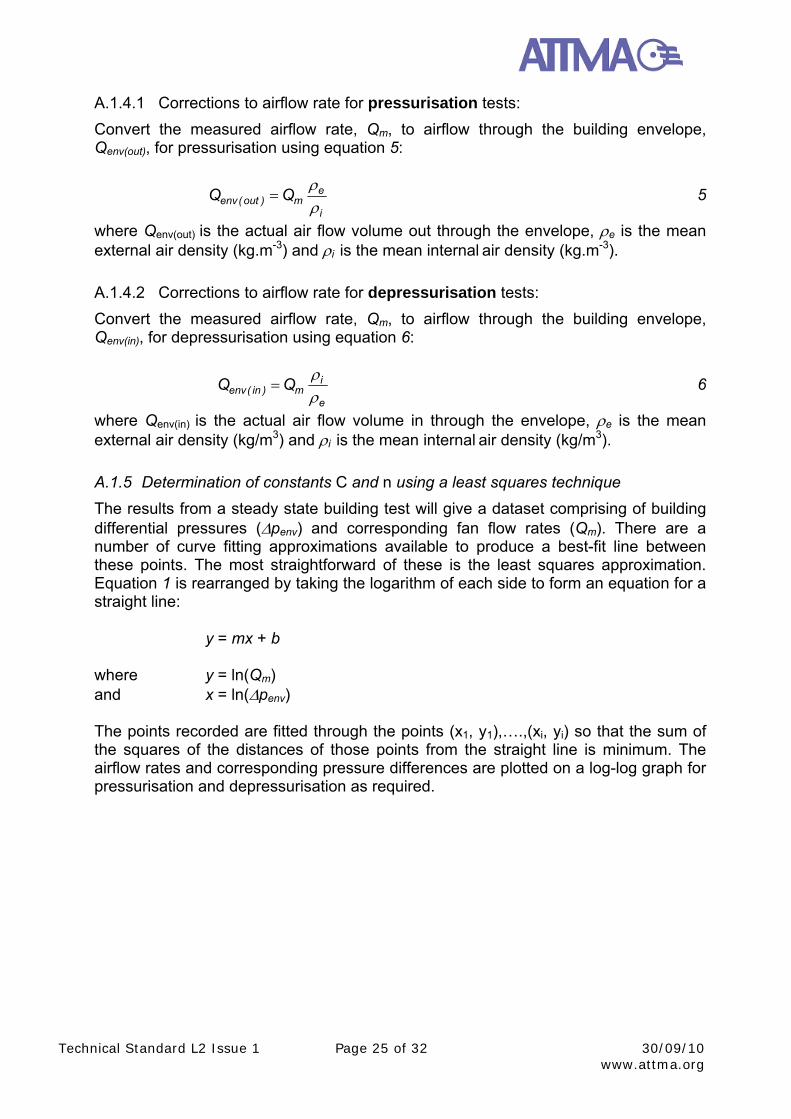
A.1.4.1 Corrections to airflow rate for pressurisation tests:
Convert the measured airflow rate, Qm, to airflow through the building envelope, Qenv(out), for pressurisation using equation 5:
i
em)out(env QQ
5
where Qenv(out) is the actual air flow volume out through the envelope, e is the mean external air density (kg.m-3) and i is the mean internal air density (kg.m-3).
A.1.4.2 Corrections to airflow rate for depressurisation tests:
Convert the measured airflow rate, Qm, to airflow through the building envelope, Qenv(in), for depressurisation using equation 6:
e
im)in(env QQ
6
where Qenv(in) is the actual air flow volume in through the envelope, e is the mean external air density (kg/m3) and i is the mean internal air density (kg/m3).
A.1.5 Determination of constants C and n using a least squares technique
The results from a steady state building test will give a dataset comprising of building differential pressures (penv) and corresponding fan flow rates (Qm). There are a number of curve fitting approximations available to produce a best-fit line between these points. The most straightforward of these is the least squares approximation. Equation 1 is rearranged by taking the logarithm of each side to form an equation for a straight line:
y = mx + b
where y = ln(Qm) and x = ln(penv) The points recorded are fitted through the points (x1, y1),….,(xi, yi) so that the sum of the squares of the distances of those points from the straight line is minimum. The airflow rates and corresponding pressure differences are plotted on a log-log graph for pressurisation and depressurisation as required.
Technical Standard L2 Issue 1 Page 26 of 32 30/09/10 www.attma.org
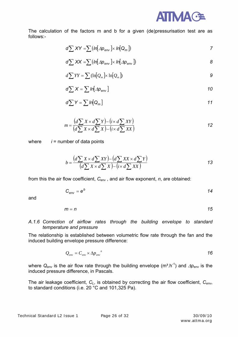
The calculation of the factors m and b for a given (de)pressurisation test are as follows:-
menv QlnplnXYd 7
envenv plnplnXXd 8
)ln(ln mm QQYYd 9
envplnXd 10
mQlnYd 11
XXdiXdXd
XYdiYdXdm 12
where i = number of data points
XXdiXdXd
YdXXdXYdXdb 13
from this the air flow coefficient, Cenv , and air flow exponent, n, are obtained:
b
env eC 14
and
nm 15
A.1.6 Correction of airflow rates through the building envelope to standard temperature and pressure
The relationship is established between volumetric flow rate through the fan and the induced building envelope pressure difference:
n
envenvenv pCQ 16
where Qenv is the air flow rate through the building envelope (m³.h-1) and penv is the induced pressure difference, in Pascals. The air leakage coefficient, CL, is obtained by correcting the air flow coefficient, Cenv, to standard conditions (i.e. 20 °C and 101,325 Pa).
Technical Standard L2 Issue 1 Page 27 of 32 30/09/10 www.attma.org
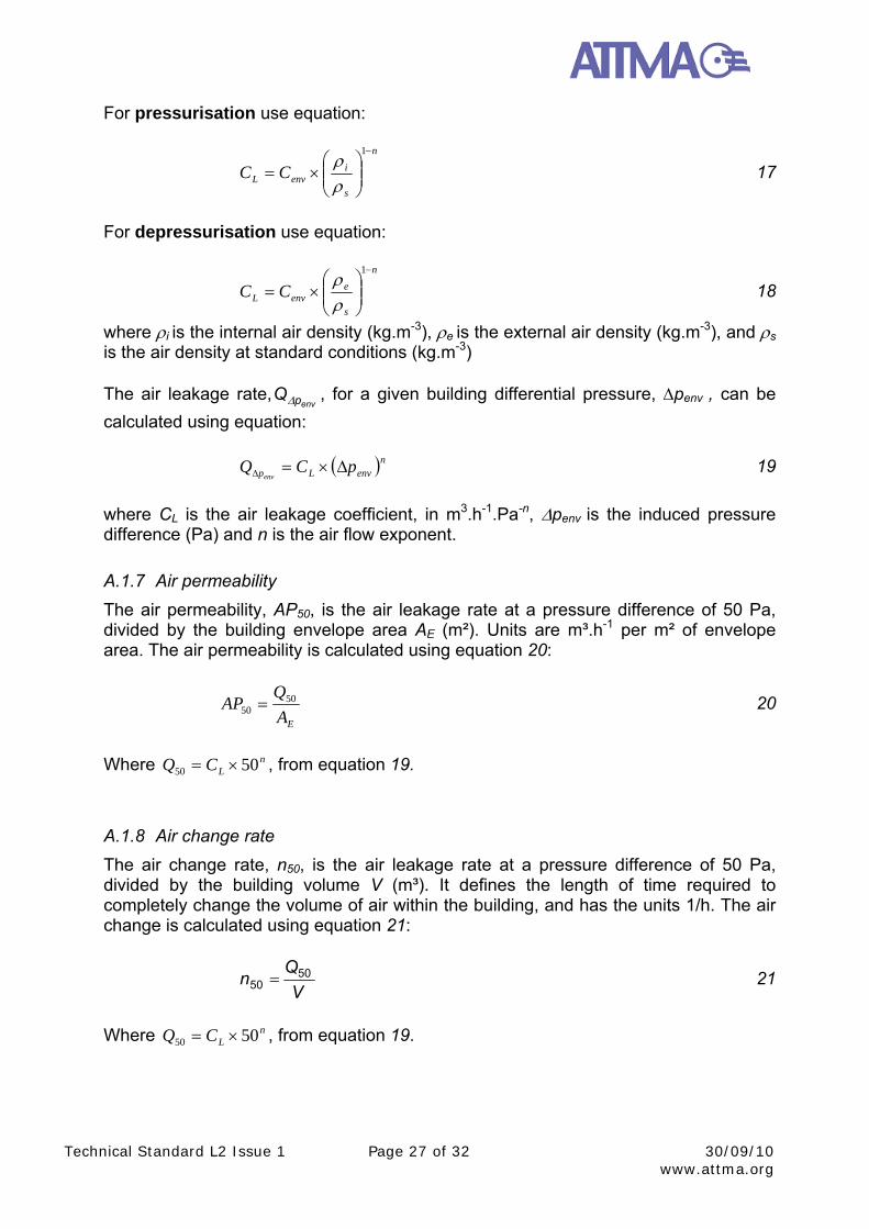
For pressurisation use equation:
n
s
ienvL CC
1
17
For depressurisation use equation:
n
s
eenvL CC
1
18
where i is the internal air density (kg.m-3), e is the external air density (kg.m-3), and s
is the air density at standard conditions (kg.m-3) The air leakage rate,
envpQ , for a given building differential pressure, penv , can be
calculated using equation:
nenvLp pCQenv
19
where CL is the air leakage coefficient, in m3.h-1.Pa-n, penv is the induced pressure difference (Pa) and n is the air flow exponent.
A.1.7 Air permeability
The air permeability, AP50, is the air leakage rate at a pressure difference of 50 Pa, divided by the building envelope area AE (m²). Units are m³.h-1 per m² of envelope area. The air permeability is calculated using equation 20:
EA
QAP 50
50 20
Where n
LCQ 5050 , from equation 19.
A.1.8 Air change rate
The air change rate, n50, is the air leakage rate at a pressure difference of 50 Pa, divided by the building volume V (m³). It defines the length of time required to completely change the volume of air within the building, and has the units 1/h. The air change is calculated using equation 21:
V
Qn 50
50 21
Where n
LCQ 5050 , from equation 19.
Technical Standard L2 Issue 1 Page 28 of 32 30/09/10 www.attma.org
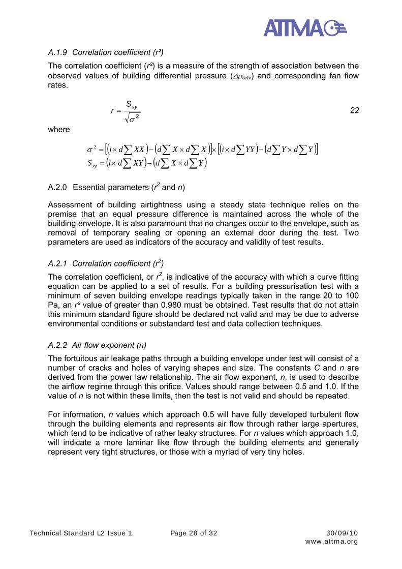
A.1.9 Correlation coefficient (r²)
The correlation coefficient (r²) is a measure of the strength of association between the observed values of building differential pressure (env) and corresponding fan flow rates.
2
xySr 22
where
YdYdYYdiXdXdXXdi2
YdXdXYdiSxy
A.2.0 Essential parameters (r2 and n)
Assessment of building airtightness using a steady state technique relies on the premise that an equal pressure difference is maintained across the whole of the building envelope. It is also paramount that no changes occur to the envelope, such as removal of temporary sealing or opening an external door during the test. Two parameters are used as indicators of the accuracy and validity of test results.
A.2.1 Correlation coefficient (r2)
The correlation coefficient, or r2, is indicative of the accuracy with which a curve fitting equation can be applied to a set of results. For a building pressurisation test with a minimum of seven building envelope readings typically taken in the range 20 to 100 Pa, an r² value of greater than 0.980 must be obtained. Test results that do not attain this minimum standard figure should be declared not valid and may be due to adverse environmental conditions or substandard test and data collection techniques.
A.2.2 Air flow exponent (n)
The fortuitous air leakage paths through a building envelope under test will consist of a number of cracks and holes of varying shapes and size. The constants C and n are derived from the power law relationship. The air flow exponent, n, is used to describe the airflow regime through this orifice. Values should range between 0.5 and 1.0. If the value of n is not within these limits, then the test is not valid and should be repeated. For information, n values which approach 0.5 will have fully developed turbulent flow through the building elements and represents air flow through rather large apertures, which tend to be indicative of rather leaky structures. For n values which approach 1.0, will indicate a more laminar like flow through the building elements and generally represent very tight structures, or those with a myriad of very tiny holes.
Technical Standard L2 Issue 1 Page 29 of 32 30/09/10 www.attma.org
A.3.0 Limiting factors
A.3.1 Static pressures within tall buildings
Buildings with large internal/external temperature differences are subject to stack pressures. These may be more pronounced in tall buildings. If the product of the temperature differential across the building envelope (ΔT), multiplied by the building height (m) is greater than 250 mC, it is likely that the stack pressure is too great to maintain an equal pressure difference across the whole of the building envelope.
A.3.2 Uniform pressures across the building envelope
In multi cellular buildings all internal doors should be opened, so that a uniform pressure is maintained across the whole of the building envelope. This may entail using a number of fans strategically located in various doorways or other openings around the envelope. Readings should be taken as outlined in section 3.5
A.3.3 Zero-flow pressure differences
Temporarily sealing is applied to the fan(s) at the start and end of the test. Readings for building differential pressures are recorded at zero airflow rate through the fan(s). If the average of the zero-flow pressure differences at the start or end of the test exceeds ±5 Pa the influence of wind and/or stack pressures are too great for a valid set of readings to be obtained.
A.3.4 Minimum acceptable building differential pressures
The building differential pressures induced during an air test should be greater than those occurring naturally to minimise the influence of wind and stack effects. A maximum pressure of at least 50 Pa must be established across the envelope, with readings typically taken up to between 60 and 100 Pascals. Higher building pressures may result in more accurate data in some instances. However, differential pressures above 100 Pa may result in the deformation of envelope components and must therefore be avoided. No readings should be recorded below 10 Pa, or five times the zero flow pressure difference, whichever is greater. In exceptional circumstances, e.g. when a building is unexpectedly leaky, it may not be possible to achieve a pressure difference of 50 Pa. In these cases, the failure to attain 50 Pa must be stated in the report, with an account of the reasons why. Readings taken at low pressures will be more adversely affected by environmental conditions and any conclusions drawn from such a report should be treated with caution.
Technical Standard L2 Issue 1 Page 30 of 32 30/09/10 www.attma.org
Appendix B - Test Equipment Requirements
B.1.0 Introduction
The requirements of ATTMA for the accuracy of measurements are based primarily around the BS EN Standard 13829:2001 - ‘Thermal Performance of Buildings - Determination of air permeability of buildings - Fan pressurisation method’ with enhancements recommended by ATTMA. All instrumentation, whatever the required tolerance, needs to satisfy the annual calibration requirements of UKAS. UKAS Certification is a mandatory requirement for all ATTMA members.
B.2.0 Accuracy
The following is a list of the required measurements and tolerances:
B.2.1 Pressure Differential Measurement (micromanometer)
An instrument capable of measuring pressure differentials with an accuracy of ±2 Pascals in the range of 0 to 100 Pascals.
B.2.2 Air Flow Rate Measurement
The device must have a UKAS accredited calibration and measure the air flow rate to within ±7% of the reading. The reading of the air flow rate shall be corrected according to air density. Care should be taken when choosing a measurement system that the system is relatively unaffected by irregular air entry conditions (wind velocities and local obstructions) and that there is stability in the measurement system. Where multiple fans and measurement systems are to be used in unison then the calibration of all individual units need to be verified and UKAS accredited.
B.2.3 Temperature Measurement devices
The accuracy of temperature measurement must have an accuracy of ±1C within the range of -20 C to + 40 C .
B.2.4 Barometric Pressure
A barometer should have an accuracy of ± 5 mbar in the range 950 - 1050 mbar. The barometer is used for correcting air flow rates and has a small effect on the measurement accuracy.
B.3.0 Calibration
Care will need to be taken in the choice of an air flow measurement system to avoid inaccuracies induced by wind effects on the flow measurement device. The proximity of local obstructions can cause inaccuracies but more particularly the proximity of two flow measurement devices, as can be found with two or more blower door type fans.
Technical Standard L2 Issue 1 Page 31 of 32 30/09/10 www.attma.org
The flow measurement device will require to be calibrated against a recognised test procedure. Such test procedures will have to satisfy UKAS requirements and two standards are worthy of reference. The first is BS ISO 3966:2008 ‘Measurement of fluid flow in closed conduits. Velocity area method using Pitot static tubes’ and the second is BS 848-1:2007 (BS EN ISO 5801:2008) ‘Industrial fans. Performance testing using standardized airways’. It will also be a UKAS requirement and by extension an ATTMA requirement to calculate estimates of uncertainties for not only the individual parameters but also a final uncertainty budget from the square root of the sum of the squares of the standard deviation of each source of uncertainty.
Technical Standard L2 Issue 1 Page 32 of 32 30/09/10 www.attma.org
Appendix C - Equivalent Leakage Area (ELA)
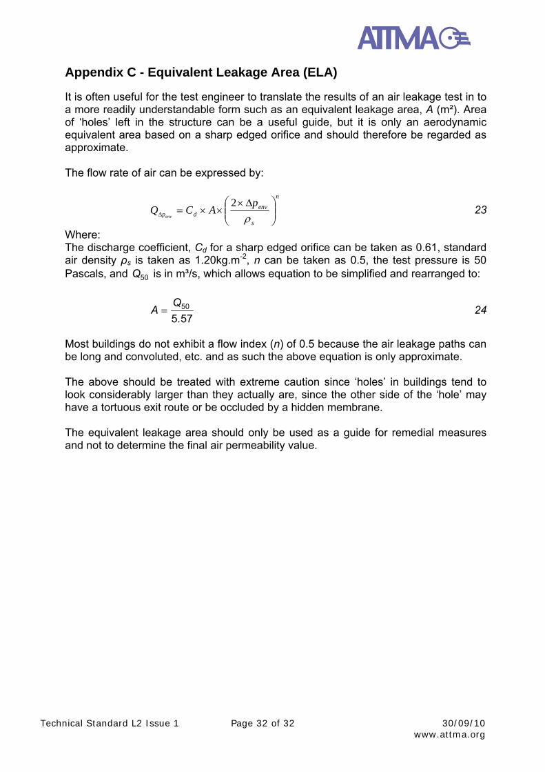
It is often useful for the test engineer to translate the results of an air leakage test in to a more readily understandable form such as an equivalent leakage area, A (m²). Area of ‘holes’ left in the structure can be a useful guide, but it is only an aerodynamic equivalent area based on a sharp edged orifice and should therefore be regarded as approximate. The flow rate of air can be expressed by:
n
s
envdp
pACQ
env
2 23
Where: The discharge coefficient, Cd for a sharp edged orifice can be taken as 0.61, standard air density ρs is taken as 1.20kg.m-2, n can be taken as 0.5, the test pressure is 50 Pascals, and 50Q is in m³/s, which allows equation to be simplified and rearranged to:
57550
.
QA 24
Most buildings do not exhibit a flow index (n) of 0.5 because the air leakage paths can be long and convoluted, etc. and as such the above equation is only approximate. The above should be treated with extreme caution since ‘holes’ in buildings tend to look considerably larger than they actually are, since the other side of the ‘hole’ may have a tortuous exit route or be occluded by a hidden membrane. The equivalent leakage area should only be used as a guide for remedial measures and not to determine the final air permeability value.