Embed Size (px)
Citation preview
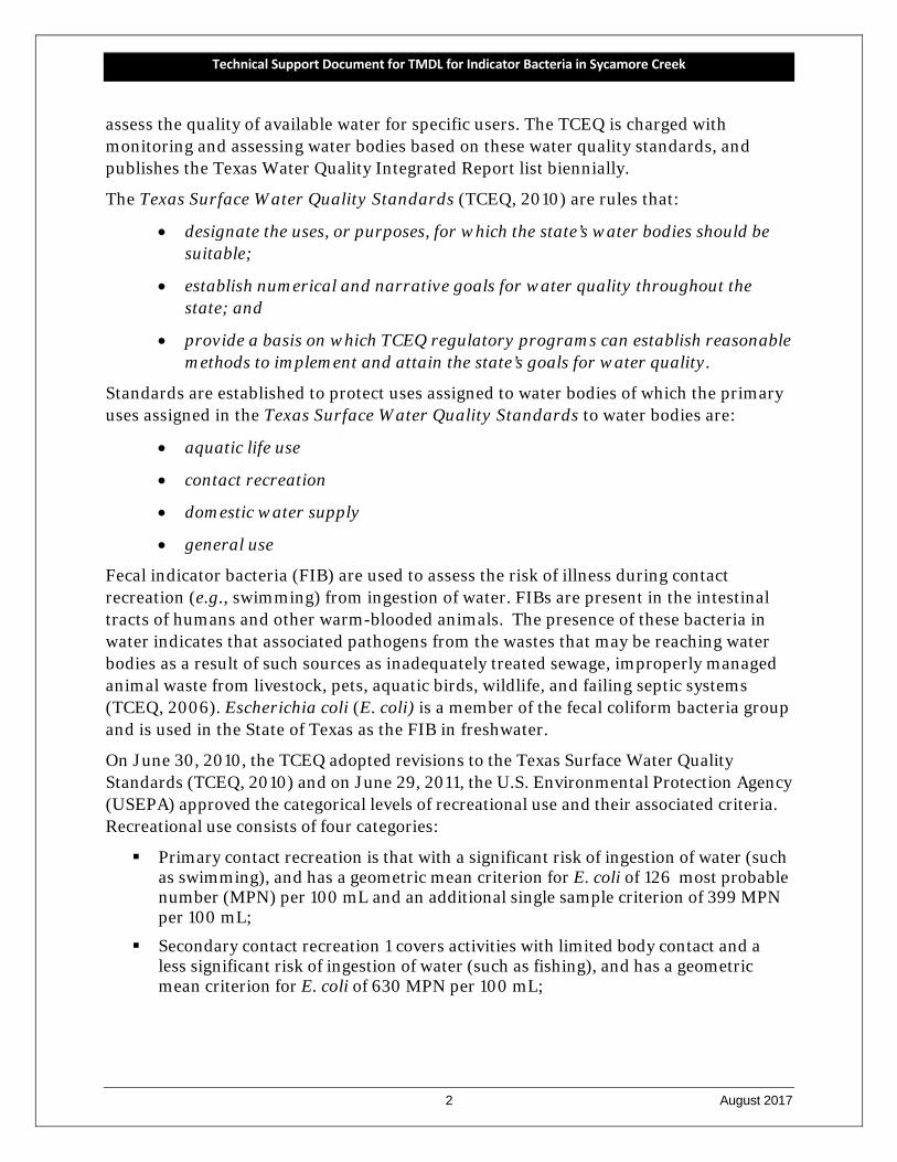
Technical Support Document for Total Maximum Daily Load for Indicator Bacteria for Sycamore Creek
Segment: 0806E Assessment Units: 0806E_01
View of Sycamore Cree (0806E), upstream of IH-20
Glen Garden Dr.
Cobb Park @
Hwy 287
Berry Rd.
Technical Support Document for Total Maximum Daily Load
for Indicator Bacteria for Sycamore Creek
Segment: 0806E
Assessment Unit: 0806E_01
Prepared for Total Maximum Daily Load Program
Texas Commission on Environmental Quality MC-203
P.O. Box 13087 Austin, Texas 78711-3087
Prepared by Jimmy Millican
Larry Hauck Texas Institute for Applied Environmental Research
Tarleton State University Stephenville, Texas
PR1704
August 2017
Technical Support Document for TMDL for Indicator Bacteria in Sycamore Creek
ii August 2017
Acknowledgements Financial support for this study was provided by the U.S. Environmental Protection Agency and the Texas Commission on Environmental Quality (TCEQ). The lead agency for this study was the Texas Commission on Environmental Quality. The administrative oversight, technical input, and review of this document by the TCEQ Project Manager, Ms. Dania Grundmann, were important to the completion of this project and the development of this document.
Technical Support Document for TMDL for Indicator Bacteria in Sycamore Creek
iii August 2017
Table of Contents ACKNOWLEDGEMENTS .................................................................................................................................................. II
TABLE OF CONTENTS .................................................................................................................................................... III
LIST OF FIGURES ............................................................................................................................................................ V
LIST OF TABLES .............................................................................................................................................................. V
ABBREVIATIONS ......................................................................................................................................................... VII
SECTION 1 ...................................................................................................................................................................... 1
INTRODUCTION ............................................................................................................................................................. 1
1.1 BACKGROUND ................................................................................................................................................................. 1 1.2 WATER QUALITY STANDARDS ............................................................................................................................................ 1 1.3 REPORT PURPOSE AND ORGANIZATION ............................................................................................................................... 3
SECTION 2 ...................................................................................................................................................................... 4
HISTORICAL DATA REVIEW AND WATERSHED PROPERTIES .......................................................................................... 4
2.1 DESCRIPTION OF STUDY AREA ............................................................................................................................................ 4 2.2 WATERSHED CLIMATE AND HYDROLOGY ............................................................................................................................. 4 2.3 WATERSHED POPULATION AND POPULATION PROJECTIONS .................................................................................................... 6 2.4 REVIEW OF ROUTINE MONITORING DATA ............................................................................................................................ 7
2.4.1 Data Acquisition ................................................................................................................... 7 2.4.2 Analysis of Bacteria Data ..................................................................................................... 7
2.5 LAND USE ...................................................................................................................................................................... 9 2.6 SOILS ........................................................................................................................................................................... 11 2.7 POTENTIAL SOURCES OF FECAL INDICATOR BACTERIA .......................................................................................................... 12
2.7.1 Permitted Sources ............................................................................................................. 13 2.7.1.1 Domestic Wastewater Treatment Facility Discharges ................................... 13 2.7.1.2 Sanitary Sewer Overflows................................................................................ 13 2.7.1.3 TPDES-Regulated Stormwater ....................................................................... 16 2.7.1.4 Dry Weather Discharges/Illicit Discharges .................................................... 17 2.7.1.5 TPDES General Wastewater Permits .............................................................. 19
2.7.2 Unregulated Sources ......................................................................................................... 19 2.7.2.1 Wildlife and Unmanaged Animal and Human Contributions ...................... 19 2.7.2.2 On-Site Sewage Facilities ............................................................................... 20 2.7.2.3 Non-Permitted Agricultural Activities and Domesticated Animals ............ 20 2.7.2.4 Bacteria Survival and Die-off ......................................................................... 22
SECTION 3 .................................................................................................................................................................... 23
BACTERIA TOOL DEVELOPMENT .................................................................................................................................. 23
3.1 TOOL SELECTION ........................................................................................................................................................... 23 3.2 SYCAMORE CREEK DATA RESOURCES ................................................................................................................................ 23 3.3 METHODOLOGY FOR FLOW DURATION & LOAD DURATION CURVE DEVELOPMENT .................................................................. 25
Technical Support Document for TMDL for Indicator Bacteria in Sycamore Creek
iv August 2017
3.3.1 Step 1: Determine Hydrologic Period ............................................................... 25 3.3.2 Step 2: Determine Desired Stream Locations ................................................. 26 3.3.3 Step 3: Develop Daily Streamflow Records ..................................................... 26 3.3.4 Steps 4-6: Flow Duration Curve and Load Duration Curve Method .............. 27
3.4: FLOW DURATION CURVE FOR SAMPLING STATION 17369 .................................................................................................. 28 3.5: LOAD DURATION CURVE FOR THE SAMPLING STATION WITHIN THE SYCAMORE CREEK WATERSHED ........................................... 29
SECTION 4 .................................................................................................................................................................... 32
TMDL ALLOCATION ANALYSIS ..................................................................................................................................... 32
4.1 ENDPOINT IDENTIFICATION .............................................................................................................................................. 32 4.2 SEASONALITY ................................................................................................................................................................ 33 4.3 LINKAGE ANALYSIS ......................................................................................................................................................... 33 4.4 LOAD DURATION CURVE ANALYSIS ................................................................................................................................... 34 4.5 MARGIN OF SAFETY ....................................................................................................................................................... 35 4.6 LOAD REDUCTION ANALYSIS ............................................................................................................................................ 35 4.7. POLLUTANT LOAD ALLOCATION ....................................................................................................................................... 36
4.7.1 Definition of TMDL Components ..................................................................... 36 4.7.2 AU-Level TMDL Calculations ........................................................................... 38
4.8 SUMMARY OF TMDL CALCULATIONS ................................................................................................................................ 41
SECTION 5 .................................................................................................................................................................... 43
REFERENCES ................................................................................................................................................................. 43
APPENDIX A ................................................................................................................................................................. 46
EQUATIONS FOR CALCULATING TMDL ALLOCATIONS FOR CHANGED CONTACT RECREATION STANDARD ............... 46
Technical Support Document for TMDL for Indicator Bacteria in Sycamore Creek
v August 2017
List of Figures Figure 1. Overview map showing the total contributing drainage area for the Sycamore Creek
watershed. ......................................................................................................................... 5 Figure 2. Average minimum and maximum air temperature and total precipitation by month
from Jan 2001 –Dec 2016 for Fort Worth Meacham Field Airport. ................................ 6 Figure 3. Sycamore Creek watershed showing TCEQ surface water quality monitoring station
used to assess primary contact recreation. ..................................................................... 8 Figure 4. 2010 land use/land cover within the Sycamore Creek watershed. .............................. 10 Figure 5. Hydrologic soil groups within the Sycamore Creek watershed. .................................... 12 Figure 6. Service area of the Fort Worth Village Creek WWTF within the Sycamore Creek
watershed. ....................................................................................................................... 14 Figure 7. Sanitary Sewer Overflows that occurred from January 2007 – December 2011 within
the Sycamore Creek watershed. ..................................................................................... 15 Figure 8. Regulated stormwater area based on Phase I and Phase II MS4s permits within the
Sycamore Creek watershed. ........................................................................................... 18 Figure 9. OSSFs located within the Sycamore Creek watershed. ................................................. 21 Figure 10. Sycamore Creek watershed and USGS Stations 08048970 and 08047050. .................. 24 Figure 11. Flow duration curve for Sycamore Creek (Station 17369). ........................................... 29 Figure 12. Load duration curve for Sycamore Creek (Station 17369) ............................................ 31
List of Tables Table 1. 2010 Population and 2040 Population Projections for the Sycamore Creek
watershed. ......................................................................................................................... 7 Table 2. 2014 Integrated Report Summary for the Sycamore Creek watershed. ........................ 9 Table 3. Land Use/Land Cover within the Sycamore Creek watershed. ..................................... 11 Table 4. Summary of SSO incidences reported in the Sycamore Creek watershed from Jan.
2009 – Dec. 2016. ............................................................................................................ 16 Table 5. TPDES and NPDES MS4 permits associated with the Sycamore Creek watershed. ..... 17 Table 6. Estimated distribution of dog and cat populations within the Sycamore Creek
watershed. ....................................................................................................................... 22 Table 7. Basic information on Village Creek and Mary Creek USGS streamflow gauges ........... 25 Table 8. DARs for the Sycamore Creek watershed based on the drainage area of the Village
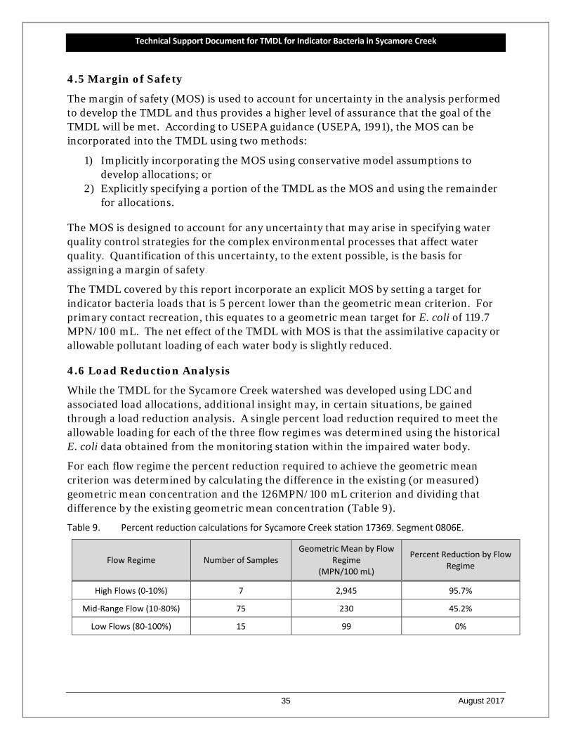
Creek and Marys Creek USGS gauges. ............................................................................ 27 Table 9. Percent reduction calculations for Sycamore Creek station 17369. ............................. 35 Table 10. Summary of allowable loading calculations for Sycamore Creek (Segment 0806E). ... 38 Table 11. MOS calculations for the Sycamore Creek Sycamore Creek watershed. ...................... 39
Technical Support Document for TMDL for Indicator Bacteria in Sycamore Creek
vi August 2017
Table 12. Basis of unregulated stormwater area and computation of FDASWP. ........................... 39 Table 13. Regulated stormwater calculations for the Sycamore Creek watershed. .................... 40 Table 14. Waste load allocation calculations for the Sycamore Creek watershed. ...................... 40 Table 15. Unregulated stormwater calculations for the Sycamore Creek watershed. ................ 40 Table 16. TMDL allocation summary for the Sycamore Creek watershed. ................................... 41 Table 17. Final TMDL allocations for the Sycamore Creek watershed. ......................................... 41
Technical Support Document for TMDL for Indicator Bacteria in Sycamore Creek
vii August 2017
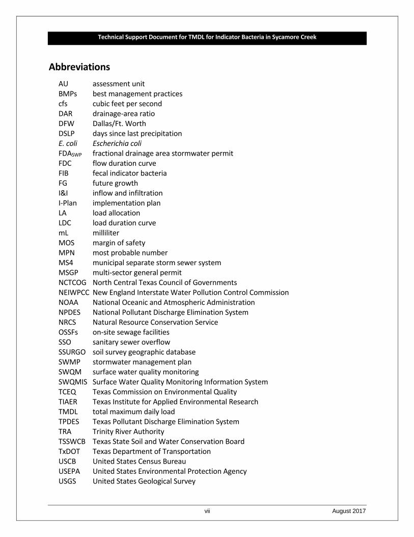
Abbreviations AU assessment unit BMPs best management practices cfs cubic feet per second DAR drainage-area ratio DFW Dallas/Ft. Worth DSLP days since last precipitation E. coli Escherichia coli FDASWP fractional drainage area stormwater permit FDC flow duration curve FIB fecal indicator bacteria FG future growth I&I inflow and infiltration I-Plan implementation plan LA load allocation LDC load duration curve mL milliliter MOS margin of safety MPN most probable number MS4 municipal separate storm sewer system MSGP multi-sector general permit NCTCOG North Central Texas Council of Governments NEIWPCC New England Interstate Water Pollution Control Commission NOAA National Oceanic and Atmospheric Administration NPDES National Pollutant Discharge Elimination System NRCS Natural Resource Conservation Service OSSFs on-site sewage facilities SSO sanitary sewer overflow SSURGO soil survey geographic database SWMP stormwater management plan SWQM surface water quality monitoring SWQMIS Surface Water Quality Monitoring Information System TCEQ Texas Commission on Environmental Quality TIAER Texas Institute for Applied Environmental Research TMDL total maximum daily load TPDES Texas Pollutant Discharge Elimination System TRA Trinity River Authority TSSWCB Texas State Soil and Water Conservation Board TxDOT Texas Department of Transportation USCB United States Census Bureau USEPA United States Environmental Protection Agency USGS United States Geological Survey
Technical Support Document for TMDL for Indicator Bacteria in Sycamore Creek
viii August 2017
WLA waste load allocation WLASW waste load allocation stormwater WLAWWTF waste load allocation wastewater treatment facilities WWTF wastewater treatment facility
Technical Support Document for TMDL for Indicator Bacteria in Sycamore Creek
1 August 2017
SECTION 1 INTRODUCTION
1.1 Background
Section 303(d) of the federal Clean Water Act requires all states to identify waters that do not meet, or are not expected to meet, applicable water quality standards. States must develop a Total Maximum Daily Load (TMDL) for each pollutant that contributes to the impairment of a listed water body. The Texas Commission on Environmental Quality (TCEQ) is responsible for ensuring that TMDLs are developed for impaired surface waters in Texas.
A TMDL is like a budget—it determines the amount of a particular pollutant that a water body can receive and still meet its applicable water quality standards. TMDLs are the best possible estimates of the assimilative capacity of the water body for a pollutant under consideration. A TMDL is commonly expressed as a load with units of mass per period of time, but may be expressed in other ways. In addition to the TMDL an implementation plan (I-Plan) is developed, which is a description of the regulatory and voluntary management measures necessary to improve water quality and restore full use of the water body.
The TCEQ’s TMDL Program is a major component of Texas’ overall process for managing the quality of its surface waters. The program addresses impaired or threatened streams, reservoirs, lakes, bays, and estuaries (water bodies) in, or bordering on, the state of Texas. The primary objective of the TMDL Program is to restore and maintain the beneficial uses—such as drinking water supply, recreation, support of aquatic life, or fishing—of impaired or threatened water bodies.
The TCEQ first identified the bacteria impairments within Sycamore Creek in 2006, and then in each subsequent edition of the Texas Water Quality Integrated Report of Surface Waters for Clean Water Act Sections 305(b) and 303 (d) (formerly called the Texas Water Quality Inventory and 303(d) List) through the 2014.
This document will consider bacteria impairments in the lone assessment unit (AU) within the segment: 0806E_01. Because the impaired segment is composed of only one AU that encompasses the entire segment, the AU descriptor (_01) is often unnecessarily cumbersome. From this point forward, AU and segment may be used interchangeably. For example, Sycamore Creek may be referred to as AU 0806E_01 or simply Segment 0806E.
1.2 Water Quality Standards
To protect public health, aquatic life, and development of industries and economies throughout Texas, water quality standards were established by the TCEQ. The water quality standards describe the limits for indicators which are monitored in an effort to
Technical Support Document for TMDL for Indicator Bacteria in Sycamore Creek
2 August 2017
assess the quality of available water for specific users. The TCEQ is charged with monitoring and assessing water bodies based on these water quality standards, and publishes the Texas Water Quality Integrated Report list biennially.
The Texas Surface Water Quality Standards (TCEQ, 2010) are rules that:
• designate the uses, or purposes, for which the state’s water bodies should be suitable;
• establish numerical and narrative goals for water quality throughout the state; and
• provide a basis on which TCEQ regulatory programs can establish reasonable methods to implement and attain the state’s goals for water quality.
Standards are established to protect uses assigned to water bodies of which the primary uses assigned in the Texas Surface Water Quality Standards to water bodies are:
• aquatic life use
• contact recreation
• domestic water supply
• general use
Fecal indicator bacteria (FIB) are used to assess the risk of illness during contact recreation (e.g., swimming) from ingestion of water. FIBs are present in the intestinal tracts of humans and other warm-blooded animals. The presence of these bacteria in water indicates that associated pathogens from the wastes that may be reaching water bodies as a result of such sources as inadequately treated sewage, improperly managed animal waste from livestock, pets, aquatic birds, wildlife, and failing septic systems (TCEQ, 2006). Escherichia coli (E. coli) is a member of the fecal coliform bacteria group and is used in the State of Texas as the FIB in freshwater.
On June 30, 2010, the TCEQ adopted revisions to the Texas Surface Water Quality Standards (TCEQ, 2010) and on June 29, 2011, the U.S. Environmental Protection Agency (USEPA) approved the categorical levels of recreational use and their associated criteria. Recreational use consists of four categories:
Primary contact recreation is that with a significant risk of ingestion of water (such as swimming), and has a geometric mean criterion for E. coli of 126 most probable number (MPN) per 100 mL and an additional single sample criterion of 399 MPN per 100 mL;
Secondary contact recreation 1 covers activities with limited body contact and a less significant risk of ingestion of water (such as fishing), and has a geometric mean criterion for E. coli of 630 MPN per 100 mL;

Technical Support Document for TMDL for Indicator Bacteria in Sycamore Creek
3 August 2017
Secondary contact recreation 2 is similar to secondary contact 1, but activities occur less frequently. It has a geometric mean criterion for E. coli of 1,030 MPN per 100 mL; and
Noncontact recreation is that with no significant risk of ingestion of water, where contact recreation should not occur due to unsafe conditions. It has a geometric mean criterion for E. coli of 2,060 MPN per 100 mL (TCEQ, 2010).
Sycamore Creek is presumed for primary contact recreation and has the associated E. coli geometric mean criterion of a 126 MPN per 100 mL and single sample criterion of 399 MPN per 100 mL.
1.3 Report Purpose and Organization
The Sycamore Creek TMDL project was initiated through a contract between the TCEQ and Texas Institute for Applied Environmental Research (TIAER). The tasks of this project were to (1) develop, have approved, and adhere to a quality assurance project plan; (2) develop a technical support document for the impaired watershed; and (3) assist the TCEQ with public participation. The purpose of this report is to provide technical documentation and supporting information for developing the bacteria TMDLs for the impaired watershed of Sycamore Creek. This report contains:
information on historical data,
watershed properties and characteristics,
summary of historical bacteria data that confirm the State of Texas 303(d) listings of impairment due to presence of indicator bacteria (E. coli),
development of load duration curves, and
application of the load duration curve approach for the pollutant load allocation process.
Technical Support Document for TMDL for Indicator Bacteria in Sycamore Creek
4 August 2017
SECTION 2 HISTORICAL DATA REVIEW AND WATERSHED PROPERTIES
2.1 Description of Study Area
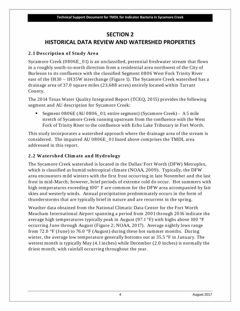
Sycamore Creek (0806E_01) is an unclassified, perennial freshwater stream that flows in a roughly south-to-north direction from a residential area northwest of the City of Burleson to its confluence with the classified Segment 0806 West Fork Trinity River east of the IH30 – IH35W interchange (Figure 1). The Sycamore Creek watershed has a drainage area of 37.0 square miles (23,688 acres) entirely located within Tarrant County.
The 2014 Texas Water Quality Integrated Report (TCEQ, 2015) provides the following segment and AU description for Sycamore Creek:
Segment 0806E (AU 0806_01; entire segment) (Sycamore Creek) - A 5 mile stretch of Sycamore Creek running upstream from the confluence with the West Fork of Trinity River to the confluence with Echo Lake Tributary in Fort Worth.
This study incorporates a watershed approach where the drainage area of the stream is considered. The impaired AU 0806E_01 listed above comprises the TMDL area addressed in this report.
2.2 Watershed Climate and Hydrology
The Sycamore Creek watershed is located in the Dallas/Fort Worth (DFW) Metroplex, which is classified as humid subtropical climate (NOAA, 2009). Typically, the DFW area encounters mild winters with the first frost occurring in late November and the last frost in mid-March; however, brief periods of extreme cold do occur. Hot summers with high temperatures exceeding 100º F are common for the DFW area accompanied by fair skies and westerly winds. Annual precipitation predominately occurs in the form of thunderstorms that are typically brief in nature and are recurrent in the spring.
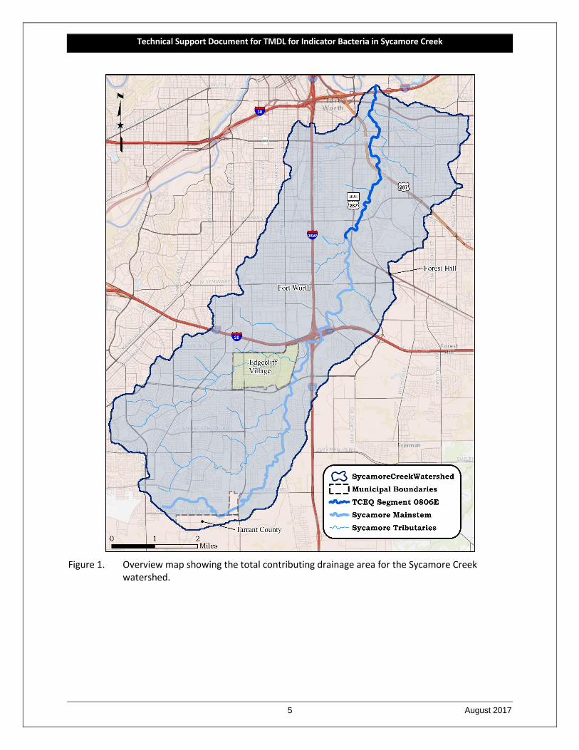
Weather data obtained from the National Climatic Data Center for the Fort Worth Meacham International Airport spanning a period from 2001 through 2016 indicate the average high temperatures typically peak in August (97.1 °F) with highs above 100 °F occurring June through August (Figure 2; NOAA, 2017). Average nightly lows range from 72.0 °F (June) to 76.0 °F (August) during these hot summer months. During winter, the average low temperature generally bottoms out at 35.5 °F in January. The wettest month is typically May (4.1 inches) while December (2.0 inches) is normally the driest month, with rainfall occurring throughout the year.
Technical Support Document for TMDL for Indicator Bacteria in Sycamore Creek
5 August 2017
Figure 1. Overview map showing the total contributing drainage area for the Sycamore Creek
watershed.
Technical Support Document for TMDL for Indicator Bacteria in Sycamore Creek
6 August 2017
Figure 2. Average minimum and maximum air temperature and total precipitation by month from
Jan 2001 –Dec 2016 for Fort Worth Meacham International Airport.
Source: NOAA (2017)
2.3 Watershed Population and Population Projections
As depicted in Figure 1, the Sycamore Creek watershed is geographically located entirely within Tarrant County, with 98.9 percent of the watershed covered by municipal boundaries (Fort Worth, Edgecliff Village, and Forest Hill) and 1.10 percent designated as “Other County” areas. It should be noted that the City of Forest Hill covers only 1.38 acres or 0.006 percent of the Sycamore Creek watershed. According to the 2010 Census data (USCB, 2017), population data indicate the Sycamore Creek watershed has an estimated population of 151,826 people. Approximately 97.7 percent of the population estimate (148,335 people) is located within the Fort Worth city limits followed by 1.8 percent Edgecliff Village with 2,782 people, indicating a largely urban watershed population.
Population projections from 2010 – 2040 were developed by utilizing data from the 2010 U.S. Census and 2040 traffic survey zone population projections developed by the North Central Texas Council of Governments (NCTCOG, 2015). Population projection

Technical Support Document for TMDL for Indicator Bacteria in Sycamore Creek
7 August 2017
increases range from 42.9 percent to 246.4 percent. Table 1 provides a summary of the 2010 – 2040 population projections.
Table 1. 2010 Population and 2040 Population Projections for the Sycamore Creek watershed.
Source: USCB (2017) and NCTCOG (2015)
Location a 2010 U. S. Census
2040 Population Projection
Projected Population
Increase (2010-2040)
Percent Change
Fort Worth 148,335 212,004 63,669 42.9%
Edgecliff Village 2,782 5,114 2,332 83.8%
Tarrant County 709 2,454 1,745 246.1%
Watershed Total 151,826 219,572 67,746 44.6%
a The City of Forest Hill with only 1.38 acres in the Sycamore Creek watershed, which is only 0.006% of the watershed area, was not considered in the watershed population information in this table.
2.4 Review of Routine Monitoring Data
2.4.1 Data Acquisition
Ambient E. coli data were obtained from the TCEQ Surface Water Quality Monitoring Information System (SWQMIS) on December 7, 2016. The data represent all the historical routine ambient E. coli and other water quality data collected in the Sycamore Creek watershed, and include E. coli data collected from January 2001 through April 2016. General assessment criteria methodologies established by TCEQ were used in data evaluations.
2.4.2 Analysis of Bacteria Data
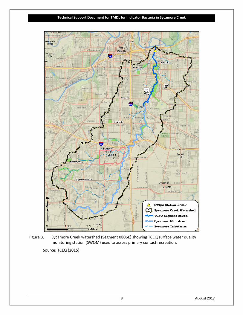
Recent environmental monitoring within the Sycamore Creek watershed has occurred at TCEQ monitoring station 17369 (Figure 4). E. coli data collected at these stations over the seven-year period of 1 December 2005 through 30 November 2012 were used in assessing attainment of the primary contact recreation use as reported in the 2014 Texas Integrated Report (TCEQ, 2015) and are summarized in Table 2. The 2014 assessment data indicate non-support of the primary contact recreation use because geometric mean concentrations exceed the E. coli geometric mean criterion of 126 MPN/100 mL for the Sycamore Creek watershed.
Technical Support Document for TMDL for Indicator Bacteria in Sycamore Creek
8 August 2017
Figure 3. Sycamore Creek watershed (Segment 0806E) showing TCEQ surface water quality
monitoring station (SWQM) used to assess primary contact recreation.
Source: TCEQ (2015)
Technical Support Document for TMDL for Indicator Bacteria in Sycamore Creek
9 August 2017
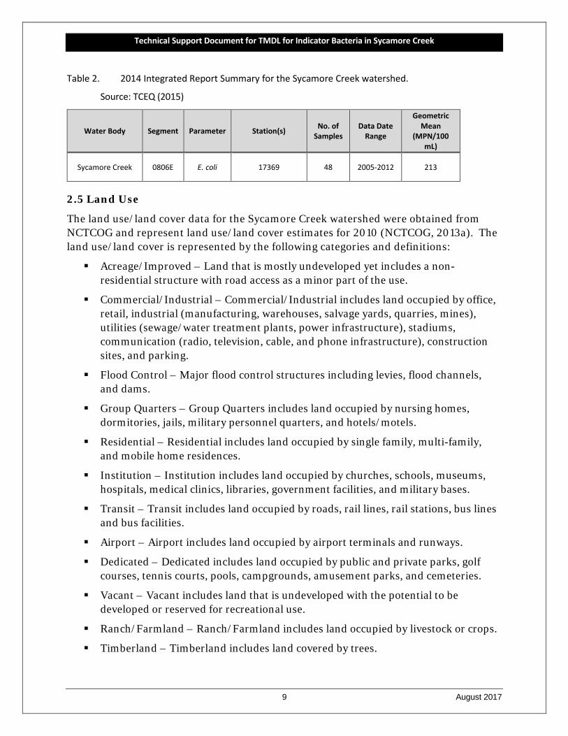
Table 2. 2014 Integrated Report Summary for the Sycamore Creek watershed.
Source: TCEQ (2015)
Water Body Segment Parameter Station(s) No. of Samples
Data Date Range
Geometric Mean
(MPN/100 mL)
Sycamore Creek 0806E E. coli 17369 48 2005-2012 213
2.5 Land Use
The land use/land cover data for the Sycamore Creek watershed were obtained from NCTCOG and represent land use/land cover estimates for 2010 (NCTCOG, 2013a). The land use/land cover is represented by the following categories and definitions:
Acreage/Improved – Land that is mostly undeveloped yet includes a non-residential structure with road access as a minor part of the use.
Commercial/Industrial – Commercial/Industrial includes land occupied by office, retail, industrial (manufacturing, warehouses, salvage yards, quarries, mines), utilities (sewage/water treatment plants, power infrastructure), stadiums, communication (radio, television, cable, and phone infrastructure), construction sites, and parking.
Flood Control – Major flood control structures including levies, flood channels, and dams.
Group Quarters – Group Quarters includes land occupied by nursing homes, dormitories, jails, military personnel quarters, and hotels/motels.
Residential – Residential includes land occupied by single family, multi-family, and mobile home residences.
Institution – Institution includes land occupied by churches, schools, museums, hospitals, medical clinics, libraries, government facilities, and military bases.
Transit – Transit includes land occupied by roads, rail lines, rail stations, bus lines and bus facilities.
Airport – Airport includes land occupied by airport terminals and runways.
Dedicated – Dedicated includes land occupied by public and private parks, golf courses, tennis courts, pools, campgrounds, amusement parks, and cemeteries.
Vacant – Vacant includes land that is undeveloped with the potential to be developed or reserved for recreational use.
Ranch/Farmland – Ranch/Farmland includes land occupied by livestock or crops.
Timberland – Timberland includes land covered by trees.
Technical Support Document for TMDL for Indicator Bacteria in Sycamore Creek
10 August 2017
Water – Water includes land covered by lakes, rivers, and ponds.
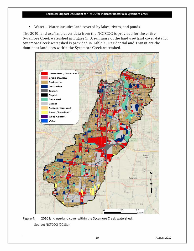
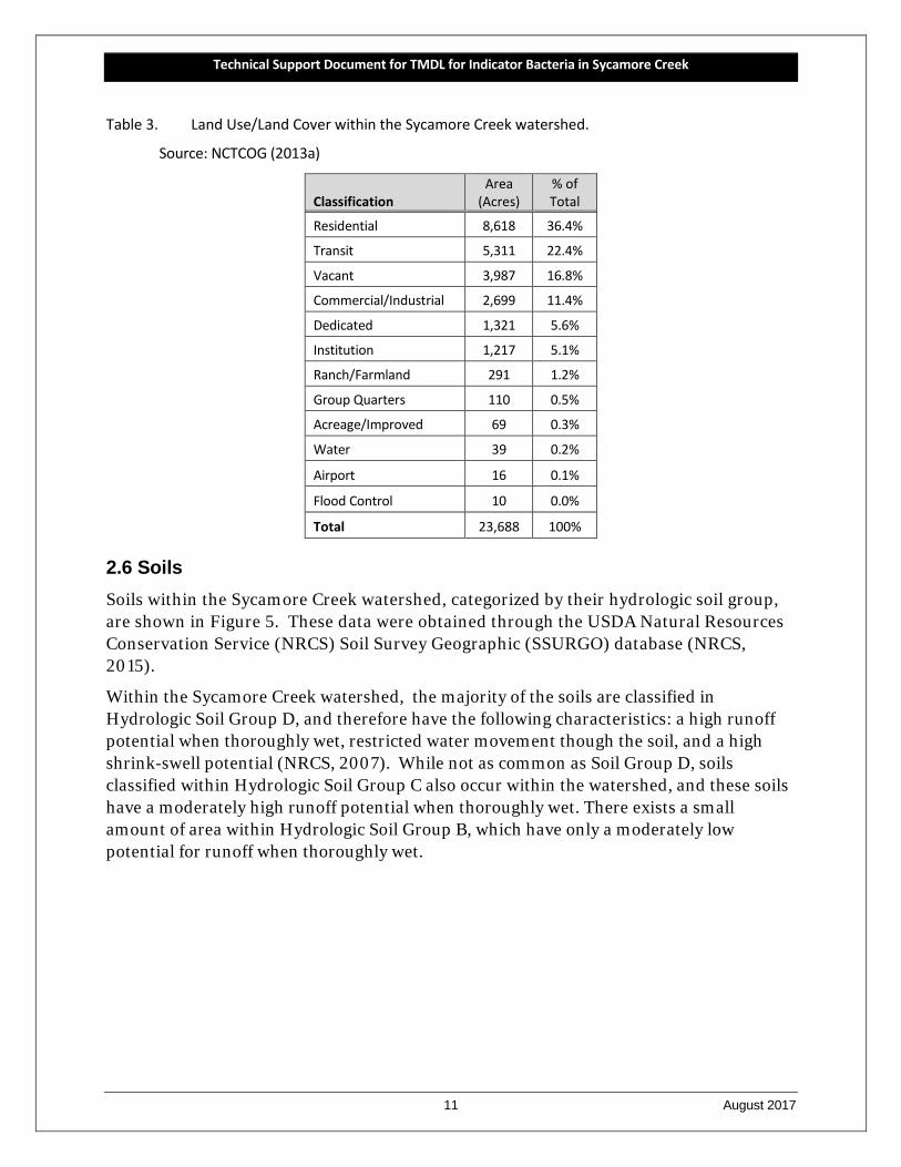
The 2010 land use/land cover data from the NCTCOG is provided for the entire Sycamore Creek watershed in Figure 5. A summary of the land use/land cover data for Sycamore Creek watershed is provided in Table 3. Residential and Transit are the dominant land uses within the Sycamore Creek watershed.
Figure 4. 2010 land use/land cover within the Sycamore Creek watershed.
Source: NCTCOG (2013a)
Technical Support Document for TMDL for Indicator Bacteria in Sycamore Creek
11 August 2017
Table 3. Land Use/Land Cover within the Sycamore Creek watershed.
Source: NCTCOG (2013a)
Classification Area
(Acres) % of Total
Residential 8,618 36.4%
Transit 5,311 22.4%
Vacant 3,987 16.8%
Commercial/Industrial 2,699 11.4%
Dedicated 1,321 5.6%
Institution 1,217 5.1%
Ranch/Farmland 291 1.2%
Group Quarters 110 0.5%
Acreage/Improved 69 0.3%
Water 39 0.2%
Airport 16 0.1%
Flood Control 10 0.0%
Total 23,688 100%
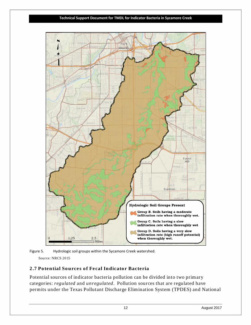
2.6 Soils Soils within the Sycamore Creek watershed, categorized by their hydrologic soil group, are shown in Figure 5. These data were obtained through the USDA Natural Resources Conservation Service (NRCS) Soil Survey Geographic (SSURGO) database (NRCS, 2015).
Within the Sycamore Creek watershed, the majority of the soils are classified in Hydrologic Soil Group D, and therefore have the following characteristics: a high runoff potential when thoroughly wet, restricted water movement though the soil, and a high shrink-swell potential (NRCS, 2007). While not as common as Soil Group D, soils classified within Hydrologic Soil Group C also occur within the watershed, and these soils have a moderately high runoff potential when thoroughly wet. There exists a small amount of area within Hydrologic Soil Group B, which have only a moderately low potential for runoff when thoroughly wet.
Technical Support Document for TMDL for Indicator Bacteria in Sycamore Creek
12 August 2017
Figure 5. Hydrologic soil groups within the Sycamore Creek watershed.
Source: NRCS 2015
2.7 Potential Sources of Fecal Indicator Bacteria
Potential sources of indicator bacteria pollution can be divided into two primary categories: regulated and unregulated. Pollution sources that are regulated have permits under the Texas Pollutant Discharge Elimination System (TPDES) and National
Technical Support Document for TMDL for Indicator Bacteria in Sycamore Creek
13 August 2017
Pollutant Discharge Elimination System (NPDES) programs. Examples of regulated sources are wastewater treatment facility (WWTF) discharges and stormwater discharges from industries, construction, and municipal separate storm sewer systems (MS4) of cities.
Unregulated sources are typically nonpoint source in nature, meaning the pollution originates from multiple locations and is usually carried to surface waters by rainfall runoff. Nonpoint sources are not regulated by permit.
With the exception of WWTFs, which receive individual waste load allocations or WLAs (see report Section 4.7.3, Waste Load Allocation), the regulated and unregulated sources in this section are presented to give a general account of the potential sources of bacteria in the watershed.
2.7.1 Permitted Sources
Permitted sources are regulated by permit under the TPDES and the NPDES programs. WWTF outfalls and stormwater discharges from industries, construction, and MS4s represent the potential permitted sources in the Sycamore Creek watershed.
2.7.1.1 Domestic Wastewater Treatment Facility Discharges
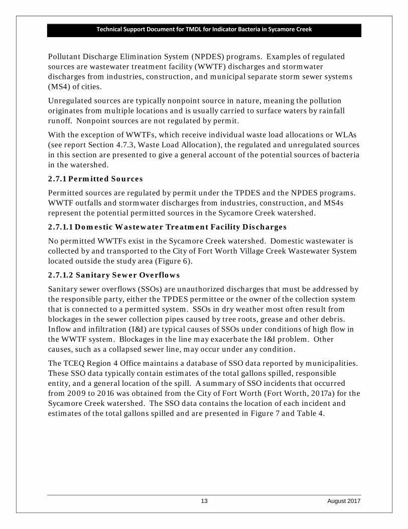
No permitted WWTFs exist in the Sycamore Creek watershed. Domestic wastewater is collected by and transported to the City of Fort Worth Village Creek Wastewater System located outside the study area (Figure 6).
2.7.1.2 Sanitary Sewer Overflows
Sanitary sewer overflows (SSOs) are unauthorized discharges that must be addressed by the responsible party, either the TPDES permittee or the owner of the collection system that is connected to a permitted system. SSOs in dry weather most often result from blockages in the sewer collection pipes caused by tree roots, grease and other debris. Inflow and infiltration (I&I) are typical causes of SSOs under conditions of high flow in the WWTF system. Blockages in the line may exacerbate the I&I problem. Other causes, such as a collapsed sewer line, may occur under any condition.
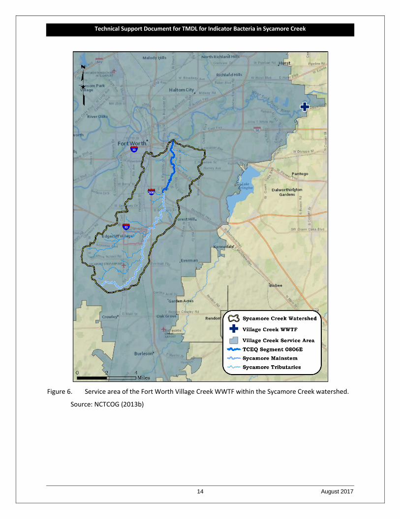
The TCEQ Region 4 Office maintains a database of SSO data reported by municipalities. These SSO data typically contain estimates of the total gallons spilled, responsible entity, and a general location of the spill. A summary of SSO incidents that occurred from 2009 to 2016 was obtained from the City of Fort Worth (Fort Worth, 2017a) for the Sycamore Creek watershed. The SSO data contains the location of each incident and estimates of the total gallons spilled and are presented in Figure 7 and Table 4.
Technical Support Document for TMDL for Indicator Bacteria in Sycamore Creek
14 August 2017
Figure 6. Service area of the Fort Worth Village Creek WWTF within the Sycamore Creek watershed.
Source: NCTCOG (2013b)
Technical Support Document for TMDL for Indicator Bacteria in Sycamore Creek
15 August 2017
Figure 7. Sanitary Sewer Overflows that occurred from January 2009 – December 2016 within the
Sycamore Creek watershed.
Source: City of Fort Worth (2017a)
Technical Support Document for TMDL for Indicator Bacteria in Sycamore Creek
16 August 2017
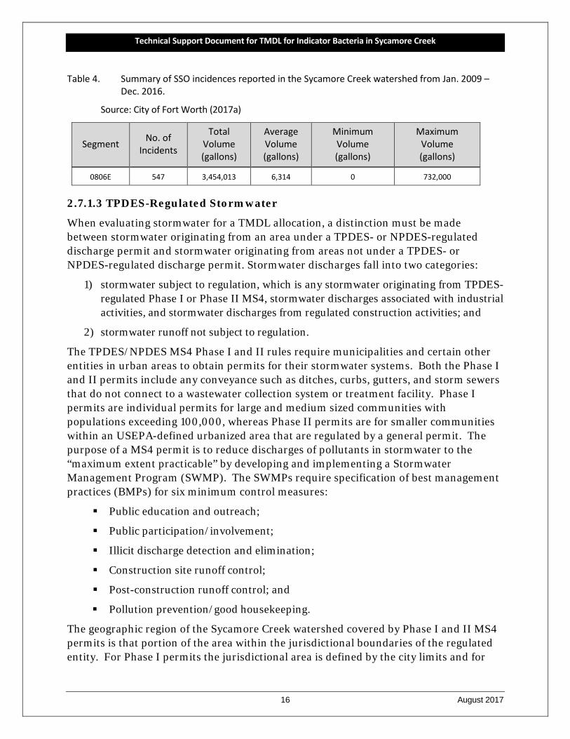
Table 4. Summary of SSO incidences reported in the Sycamore Creek watershed from Jan. 2009 – Dec. 2016.
Source: City of Fort Worth (2017a)
Segment No. of Incidents
Total Volume (gallons)
Average Volume (gallons)
Minimum Volume (gallons)
Maximum Volume (gallons)
0806E 547 3,454,013 6,314 0 732,000
2.7.1.3 TPDES-Regulated Stormwater
When evaluating stormwater for a TMDL allocation, a distinction must be made between stormwater originating from an area under a TPDES- or NPDES-regulated discharge permit and stormwater originating from areas not under a TPDES- or NPDES-regulated discharge permit. Stormwater discharges fall into two categories:
1) stormwater subject to regulation, which is any stormwater originating from TPDES-regulated Phase I or Phase II MS4, stormwater discharges associated with industrial activities, and stormwater discharges from regulated construction activities; and
2) stormwater runoff not subject to regulation.
The TPDES/NPDES MS4 Phase I and II rules require municipalities and certain other entities in urban areas to obtain permits for their stormwater systems. Both the Phase I and II permits include any conveyance such as ditches, curbs, gutters, and storm sewers that do not connect to a wastewater collection system or treatment facility. Phase I permits are individual permits for large and medium sized communities with populations exceeding 100,000, whereas Phase II permits are for smaller communities within an USEPA-defined urbanized area that are regulated by a general permit. The purpose of a MS4 permit is to reduce discharges of pollutants in stormwater to the “maximum extent practicable” by developing and implementing a Stormwater Management Program (SWMP). The SWMPs require specification of best management practices (BMPs) for six minimum control measures:
Public education and outreach;
Public participation/involvement;
Illicit discharge detection and elimination;
Construction site runoff control;
Post-construction runoff control; and
Pollution prevention/good housekeeping.
The geographic region of the Sycamore Creek watershed covered by Phase I and II MS4 permits is that portion of the area within the jurisdictional boundaries of the regulated entity. For Phase I permits the jurisdictional area is defined by the city limits and for
Technical Support Document for TMDL for Indicator Bacteria in Sycamore Creek
17 August 2017
Phase II permits the jurisdictional area is defined as the intersection or overlapping areas of the city limits and the 2000 or 2010 Census Urbanized Area.
For the Sycamore Creek watershed containing entities with Phase II general permits and Phase I individual permits, the areas included under these MS4 permits were used to estimate the regulated stormwater areas for construction, industrial and MS4 permits (Figure 8). The regulated area for the Phase II permits was based on the 2010 Urbanized Area from the U.S. Bureau of Census.
A review of active stormwater general permits coverage and a review of the central registry for Phase I MS4 permit coverage (TCEQ, 2017) in the Sycamore Creek watershed revealed that one Phase I and two Phase II permits (Table 5) exist providing 100 percent MS4 coverage for the Sycamore Creek watershed (Figure 8).
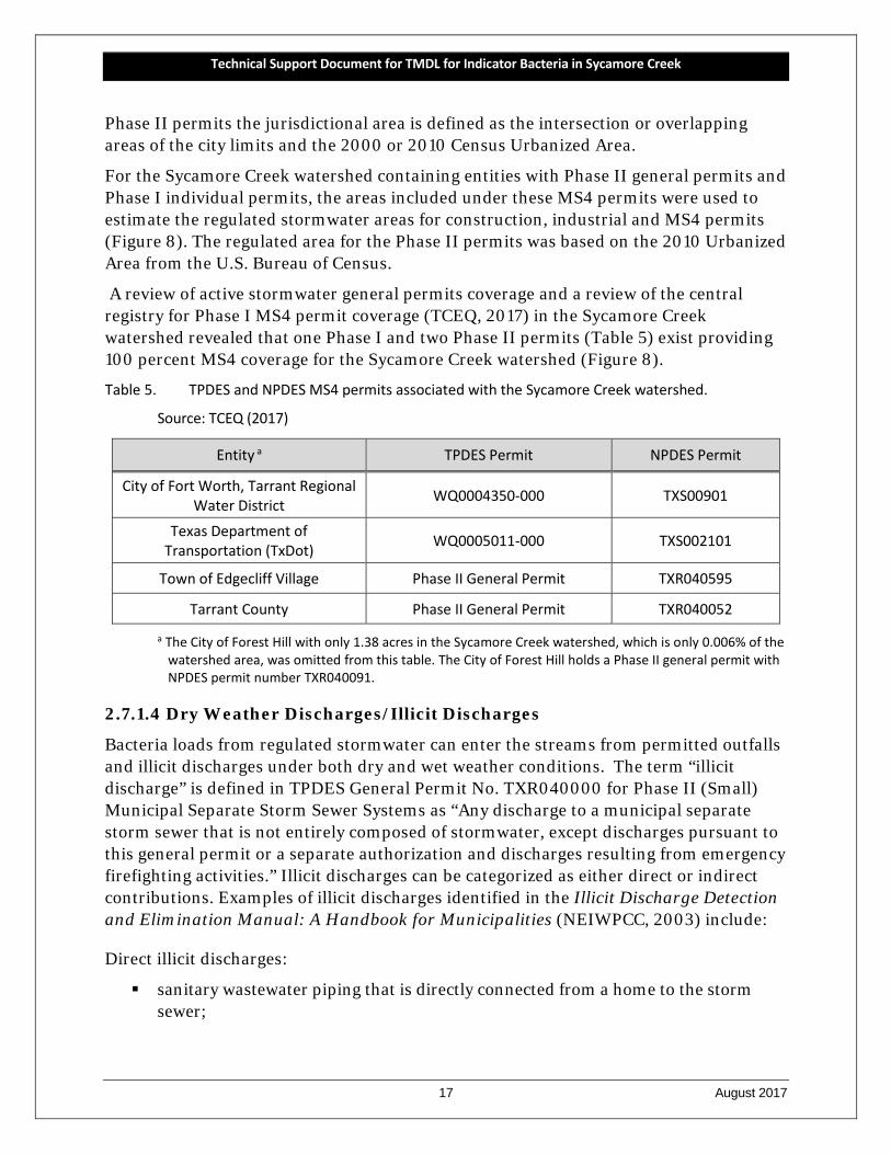
Table 5. TPDES and NPDES MS4 permits associated with the Sycamore Creek watershed.
Source: TCEQ (2017)
Entity a TPDES Permit NPDES Permit
City of Fort Worth, Tarrant Regional Water District WQ0004350-000 TXS00901
Texas Department of Transportation (TxDot) WQ0005011-000 TXS002101
Town of Edgecliff Village Phase II General Permit TXR040595
Tarrant County Phase II General Permit TXR040052
a The City of Forest Hill with only 1.38 acres in the Sycamore Creek watershed, which is only 0.006% of the watershed area, was omitted from this table. The City of Forest Hill holds a Phase II general permit with NPDES permit number TXR040091.
2.7.1.4 Dry Weather Discharges/Illicit Discharges
Bacteria loads from regulated stormwater can enter the streams from permitted outfalls and illicit discharges under both dry and wet weather conditions. The term “illicit discharge” is defined in TPDES General Permit No. TXR040000 for Phase II (Small) Municipal Separate Storm Sewer Systems as “Any discharge to a municipal separate storm sewer that is not entirely composed of stormwater, except discharges pursuant to this general permit or a separate authorization and discharges resulting from emergency firefighting activities.” Illicit discharges can be categorized as either direct or indirect contributions. Examples of illicit discharges identified in the Illicit Discharge Detection and Elimination Manual: A Handbook for Municipalities (NEIWPCC, 2003) include:
Direct illicit discharges:
sanitary wastewater piping that is directly connected from a home to the storm sewer;
Technical Support Document for TMDL for Indicator Bacteria in Sycamore Creek
18 August 2017
materials (e.g., used motor oil) that have been dumped illegally into a storm drain catch basin;
a shop floor drain that is connected to the storm sewer; and a cross-connection between the municipal sewer and storm sewer systems.
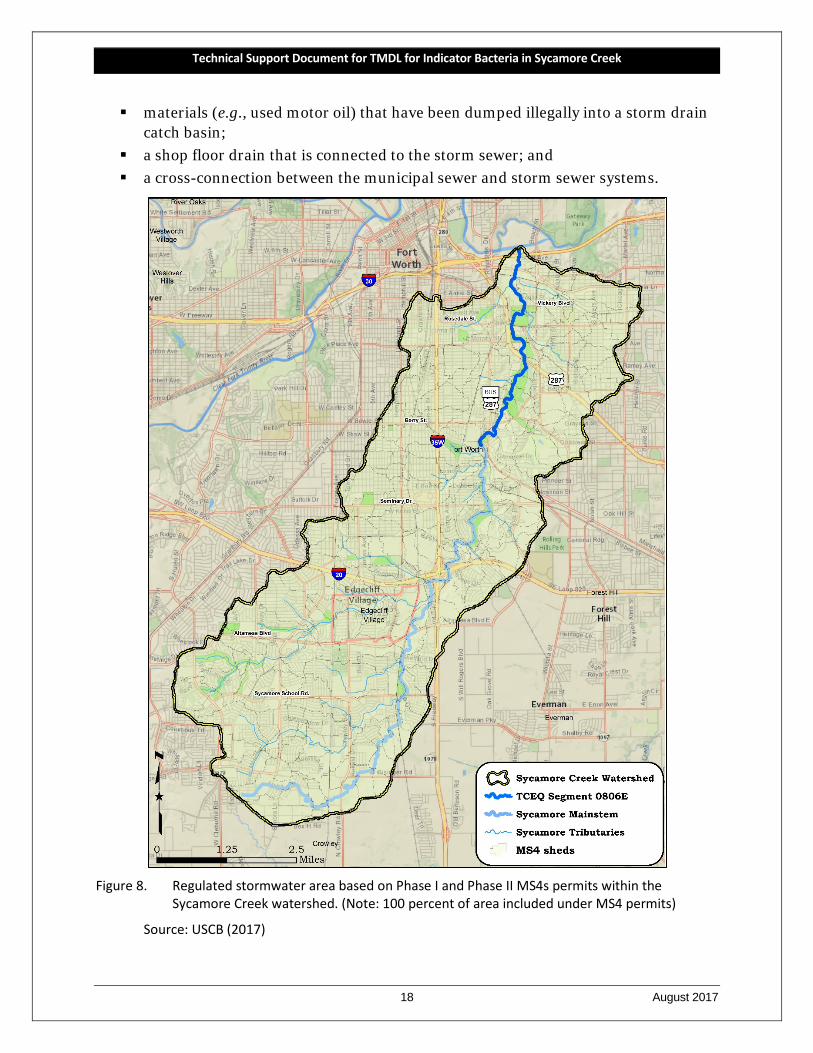
Figure 8. Regulated stormwater area based on Phase I and Phase II MS4s permits within the
Sycamore Creek watershed. (Note: 100 percent of area included under MS4 permits)
Source: USCB (2017)
Technical Support Document for TMDL for Indicator Bacteria in Sycamore Creek
19 August 2017
Indirect illicit discharges:
an old and damaged sanitary sewer line that is leaking fluids into a cracked storm sewer line; and
a failing septic system that is leaking into a cracked storm sewer line or causing surface discharge into the storm sewer.
2.7.1.5 TPDES General Wastewater Permits
Discharges of processed wastewater from certain types of facilities are required to be covered by one of several TPDES general permits:
TXG110000 – concrete production facilities TXG130000 – aquaculture production facilities TXG340000 – petroleum bulk stations and terminals TXG500000 – quarries in John Graves Scenic Riverway TXG670000 – hydrostatic test water TXG830000 – petroleum fuel or petroleum substances TXG870000 – pesticides TXG920000 – concentrated animal feeding operations TXG100000 – wastewater evaporation WQG20000 – livestock manure compost operations (irrigation only)
A review of active general permit coverage (TCEQ, 2017) in the Sycamore Creek watershed as of August 2017 found five concrete production facilities covered by general permit. The concrete production facilities do not have bacteria reporting requirements or limits in their permits. The facilities are assumed to contain inconsequential amounts of indicator bacteria in their effluent; therefore, it was unnecessary to allocate bacteria loads to these concrete production facilities. No other active general wastewater permit facilities or operations were found in the Sycamore Creek watershed.
2.7.2 Unregulated Sources
Unregulated sources of indicator bacteria are generally nonpoint and can emanate from wildlife, feral hogs, various agricultural activities, agricultural animals, land application fields, urban runoff not covered by a permit, failing onsite sewage facilities (OSSFs), and domestic pets.
2.7.2.1 Wildlife and Unmanaged Animal and Human Contributions
E. coli bacteria are common inhabitants of the intestines of all warm-blooded animals, including feral hogs and wildlife such as mammals and birds. In developing bacteria TMDLs, it is important to identify by watershed the potential for bacteria contributions from wildlife and feral hogs. Wildlife and feral hogs are naturally attracted to riparian corridors of streams and rivers. With direct access to the stream channel, the direct
Technical Support Document for TMDL for Indicator Bacteria in Sycamore Creek
20 August 2017
deposition of wildlife and feral hog waste can be a concentrated source of bacteria loading to a water body. Fecal bacteria from wildlife and feral hogs are also deposited onto land surfaces, where it may be washed into nearby streams by rainfall runoff. The E.coli contribution from feral hogs and wildlife in the Sycamore Creek cannot be determined based on existing information.
Adding to the wildlife and feral hog bacteria contributions are contributions from humans. A homeless population of variable size resides at least seasonally in the northern portion of the Sycamore Creek watershed. It is not uncommon for encampments of the homeless to be encountered by field sampling personnel of the City of Fort Worth. As with other unmanaged sources, the E. coli contribution from the homeless population cannot be estimated based on existing information.
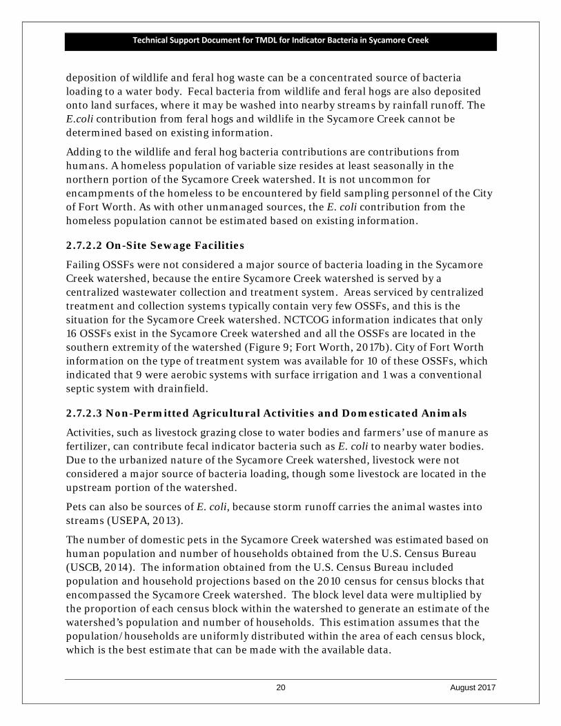
2.7.2.2 On-Site Sewage Facilities
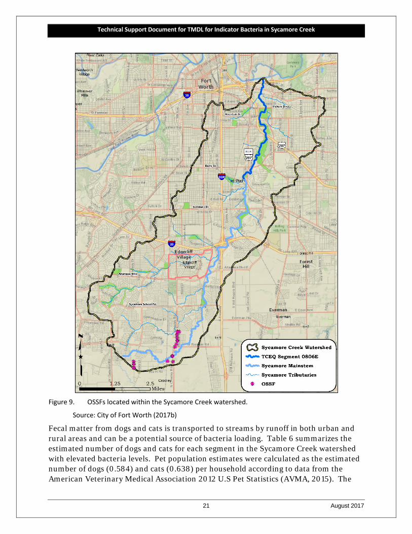
Failing OSSFs were not considered a major source of bacteria loading in the Sycamore Creek watershed, because the entire Sycamore Creek watershed is served by a centralized wastewater collection and treatment system. Areas serviced by centralized treatment and collection systems typically contain very few OSSFs, and this is the situation for the Sycamore Creek watershed. NCTCOG information indicates that only 16 OSSFs exist in the Sycamore Creek watershed and all the OSSFs are located in the southern extremity of the watershed (Figure 9; Fort Worth, 2017b). City of Fort Worth information on the type of treatment system was available for 10 of these OSSFs, which indicated that 9 were aerobic systems with surface irrigation and 1 was a conventional septic system with drainfield.
2.7.2.3 Non-Permitted Agricultural Activities and Domesticated Animals
Activities, such as livestock grazing close to water bodies and farmers’ use of manure as fertilizer, can contribute fecal indicator bacteria such as E. coli to nearby water bodies. Due to the urbanized nature of the Sycamore Creek watershed, livestock were not considered a major source of bacteria loading, though some livestock are located in the upstream portion of the watershed.
Pets can also be sources of E. coli, because storm runoff carries the animal wastes into streams (USEPA, 2013).
The number of domestic pets in the Sycamore Creek watershed was estimated based on human population and number of households obtained from the U.S. Census Bureau (USCB, 2014). The information obtained from the U.S. Census Bureau included population and household projections based on the 2010 census for census blocks that encompassed the Sycamore Creek watershed. The block level data were multiplied by the proportion of each census block within the watershed to generate an estimate of the watershed’s population and number of households. This estimation assumes that the population/households are uniformly distributed within the area of each census block, which is the best estimate that can be made with the available data.
Technical Support Document for TMDL for Indicator Bacteria in Sycamore Creek
21 August 2017
Figure 9. OSSFs located within the Sycamore Creek watershed.
Source: City of Fort Worth (2017b)
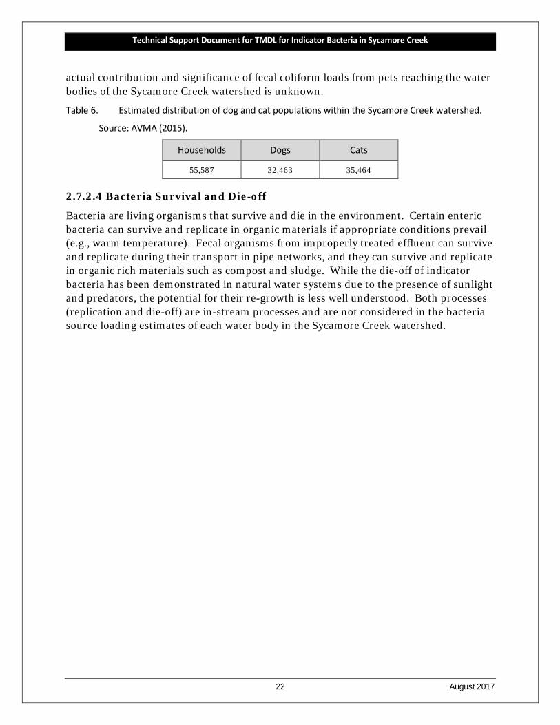
Fecal matter from dogs and cats is transported to streams by runoff in both urban and rural areas and can be a potential source of bacteria loading. Table 6 summarizes the estimated number of dogs and cats for each segment in the Sycamore Creek watershed with elevated bacteria levels. Pet population estimates were calculated as the estimated number of dogs (0.584) and cats (0.638) per household according to data from the American Veterinary Medical Association 2012 U.S Pet Statistics (AVMA, 2015). The
Technical Support Document for TMDL for Indicator Bacteria in Sycamore Creek
22 August 2017
actual contribution and significance of fecal coliform loads from pets reaching the water bodies of the Sycamore Creek watershed is unknown.
Table 6. Estimated distribution of dog and cat populations within the Sycamore Creek watershed.
Source: AVMA (2015).
Households Dogs Cats
55,587 32,463 35,464
2.7.2.4 Bacteria Survival and Die-off
Bacteria are living organisms that survive and die in the environment. Certain enteric bacteria can survive and replicate in organic materials if appropriate conditions prevail (e.g., warm temperature). Fecal organisms from improperly treated effluent can survive and replicate during their transport in pipe networks, and they can survive and replicate in organic rich materials such as compost and sludge. While the die-off of indicator bacteria has been demonstrated in natural water systems due to the presence of sunlight and predators, the potential for their re-growth is less well understood. Both processes (replication and die-off) are in-stream processes and are not considered in the bacteria source loading estimates of each water body in the Sycamore Creek watershed.
Technical Support Document for TMDL for Indicator Bacteria in Sycamore Creek
23 August 2017
SECTION 3 BACTERIA TOOL DEVELOPMENT
This section describes the rationale of the bacteria tool selection for TMDL development and details the procedures and results of load duration curve (LDC) development.
3.1 Tool Selection
For consistency between this TMDL and the previously completed TMDLs in the DFW area, the pollutant load allocation activities for the Sycamore Creek used the LDC method. The LDC method has been previously used on TCEQ adopted and USEPA approved TMDLs for the Upper Trinity River (TCEQ, 2011a), Cottonwood Branch and Grapevine Creek (TCEQ, 2011a), Lower West Fork Trinity River and tributaries (TCEQ, 2013), and Mountain Creek Lake Upstream watersheds (TCEQ, 2016). Development activities of LDCs under the present project were covered under a TCEQ-approved QAPP (TIAER, 2016).
The LDC method allows for estimation of existing and allowable loads by utilizing the cumulative frequency distribution of streamflow and measured pollutant concentration data (Cleland, 2003). In addition to estimating stream loads, the LDC method allows for the determination of the hydrologic conditions under which impairments are typically occurring. This information can be used to identify broad categories of sources (point and nonpoint) that may be contributing to the impairment. The LDC method has found relatively broad acceptance among the regulatory community, primarily due to the simplicity of the approach and ease of application. The regulatory community recognizes the frequent information limitations, often associated with bacteria TMDLs that constrain the use of more powerful mechanistic models. Further, the bacteria task force appointed by the TCEQ and the Texas State Soil and Water Conservation Board (TSSWCB) supports application of the LDC method within their three-tiered approach to TMDL development (Jones et al., 2009). The LDC method provides a means to estimate the difference in bacteria loads and relevant criterion, and can give indications of broad sources of the bacteria, i.e., point source and nonpoint source.
3.2 Sycamore Creek Data Resources
Successful application of the LDC method requires two basic types of data: continuous daily streamflow data and historical bacteria data for the relevant indicator bacteria, which in this case is E. coli.
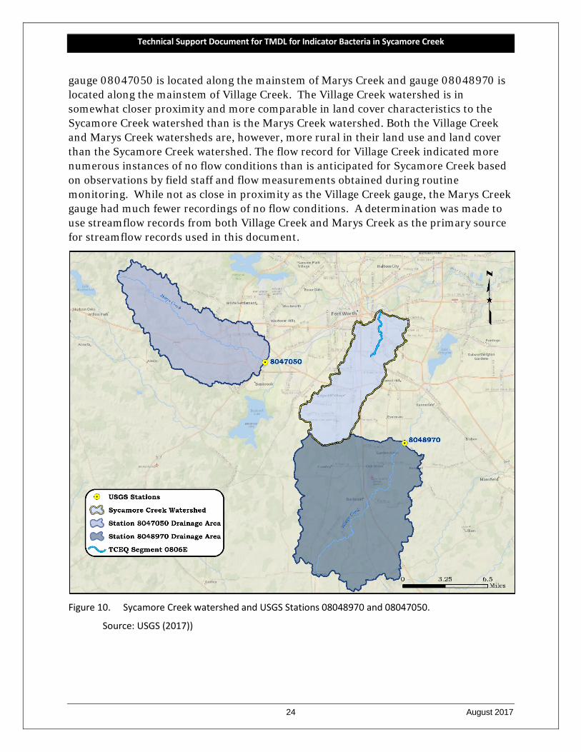
Hydrologic data in the form of daily streamflow records were unavailable for the Sycamore Creek watershed; however, streamflow records were available for the Marys Creek and Village Creek watersheds. Streamflow records for Marys Creek and Village Creek are collected and made readily available by the U.S. Geological Survey (USGS, 2017), which operates both streamflow gauges (Table 7, Figure 10). USGS streamflow
Technical Support Document for TMDL for Indicator Bacteria in Sycamore Creek
24 August 2017
gauge 08047050 is located along the mainstem of Marys Creek and gauge 08048970 is located along the mainstem of Village Creek. The Village Creek watershed is in somewhat closer proximity and more comparable in land cover characteristics to the Sycamore Creek watershed than is the Marys Creek watershed. Both the Village Creek and Marys Creek watersheds are, however, more rural in their land use and land cover than the Sycamore Creek watershed. The flow record for Village Creek indicated more numerous instances of no flow conditions than is anticipated for Sycamore Creek based on observations by field staff and flow measurements obtained during routine monitoring. While not as close in proximity as the Village Creek gauge, the Marys Creek gauge had much fewer recordings of no flow conditions. A determination was made to use streamflow records from both Village Creek and Marys Creek as the primary source for streamflow records used in this document.
Figure 10. Sycamore Creek watershed and USGS Stations 08048970 and 08047050.
Source: USGS (2017))
Technical Support Document for TMDL for Indicator Bacteria in Sycamore Creek
25 August 2017
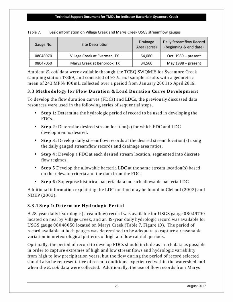
Table 7. Basic information on Village Creek and Marys Creek USGS streamflow gauges
Gauge No. Site Description Drainage Area (acres)
Daily Streamflow Record (beginning & end date)
08048970 Village Creek at Everman, TX. 54,080 Oct. 1989 – present
08047050 Marys Creek at Benbrook, TX 34,560 May 1998 – present
Ambient E. coli data were available through the TCEQ SWQMIS for Sycamore Creek sampling station 17369, and consisted of 97 E. coli sample results with a geometric mean of 243 MPN/100mL collected over a period from January 2001 to April 2016.
3.3 Methodology for Flow Duration & Load Duration Curve Development
To develop the flow duration curves (FDCs) and LDCs, the previously discussed data resources were used in the following series of sequential steps.
Step 1: Determine the hydrologic period of record to be used in developing the FDCs.
Step 2: Determine desired stream location(s) for which FDC and LDC development is desired.
Step 3: Develop daily streamflow records at the desired stream location(s) using the daily gauged streamflow records and drainage area ratios.
Step 4: Develop a FDC at each desired stream location, segmented into discrete flow regimes.
Step 5 Develop the allowable bacteria LDC at the same stream location(s) based on the relevant criteria and the data from the FDC.
Step 6: Superpose historical bacteria data on each allowable bacteria LDC.
Additional information explaining the LDC method may be found in Cleland (2003) and NDEP (2003).
3.3.1 Step 1: Determine Hydrologic Period
A 28-year daily hydrologic (streamflow) record was available for USGS gauge 08049700 located on nearby Village Creek, and an 19-year daily hydrologic record was available for USGS gauge 08048050 located on Marys Creek (Table 7, Figure 10). The period of record available at both gauges was determined to be adequate to capture a reasonable variation in meteorological patterns of high and low rainfall periods.
Optimally, the period of record to develop FDCs should include as much data as possible in order to capture extremes of high and low streamflows and hydrologic variability from high to low precipitation years, but the flow during the period of record selected should also be representative of recent conditions experienced within the watershed and when the E. coli data were collected. Additionally, the use of flow records from Marys
Technical Support Document for TMDL for Indicator Bacteria in Sycamore Creek
26 August 2017
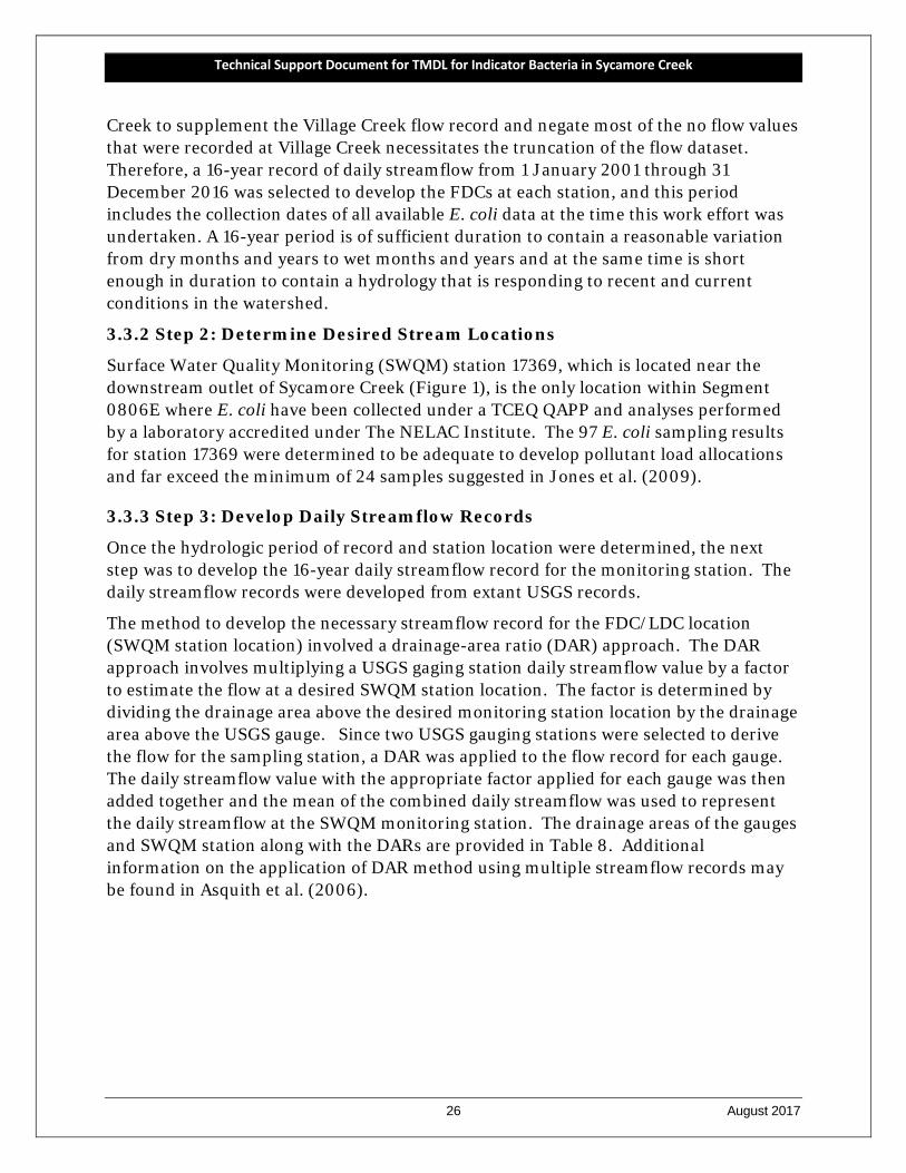
Creek to supplement the Village Creek flow record and negate most of the no flow values that were recorded at Village Creek necessitates the truncation of the flow dataset. Therefore, a 16-year record of daily streamflow from 1 January 2001 through 31 December 2016 was selected to develop the FDCs at each station, and this period includes the collection dates of all available E. coli data at the time this work effort was undertaken. A 16-year period is of sufficient duration to contain a reasonable variation from dry months and years to wet months and years and at the same time is short enough in duration to contain a hydrology that is responding to recent and current conditions in the watershed.
3.3.2 Step 2: Determine Desired Stream Locations
Surface Water Quality Monitoring (SWQM) station 17369, which is located near the downstream outlet of Sycamore Creek (Figure 1), is the only location within Segment 0806E where E. coli have been collected under a TCEQ QAPP and analyses performed by a laboratory accredited under The NELAC Institute. The 97 E. coli sampling results for station 17369 were determined to be adequate to develop pollutant load allocations and far exceed the minimum of 24 samples suggested in Jones et al. (2009).
3.3.3 Step 3: Develop Daily Streamflow Records
Once the hydrologic period of record and station location were determined, the next step was to develop the 16-year daily streamflow record for the monitoring station. The daily streamflow records were developed from extant USGS records.
The method to develop the necessary streamflow record for the FDC/LDC location (SWQM station location) involved a drainage-area ratio (DAR) approach. The DAR approach involves multiplying a USGS gaging station daily streamflow value by a factor to estimate the flow at a desired SWQM station location. The factor is determined by dividing the drainage area above the desired monitoring station location by the drainage area above the USGS gauge. Since two USGS gauging stations were selected to derive the flow for the sampling station, a DAR was applied to the flow record for each gauge. The daily streamflow value with the appropriate factor applied for each gauge was then added together and the mean of the combined daily streamflow was used to represent the daily streamflow at the SWQM monitoring station. The drainage areas of the gauges and SWQM station along with the DARs are provided in Table 8. Additional information on the application of DAR method using multiple streamflow records may be found in Asquith et al. (2006).
Technical Support Document for TMDL for Indicator Bacteria in Sycamore Creek
27 August 2017
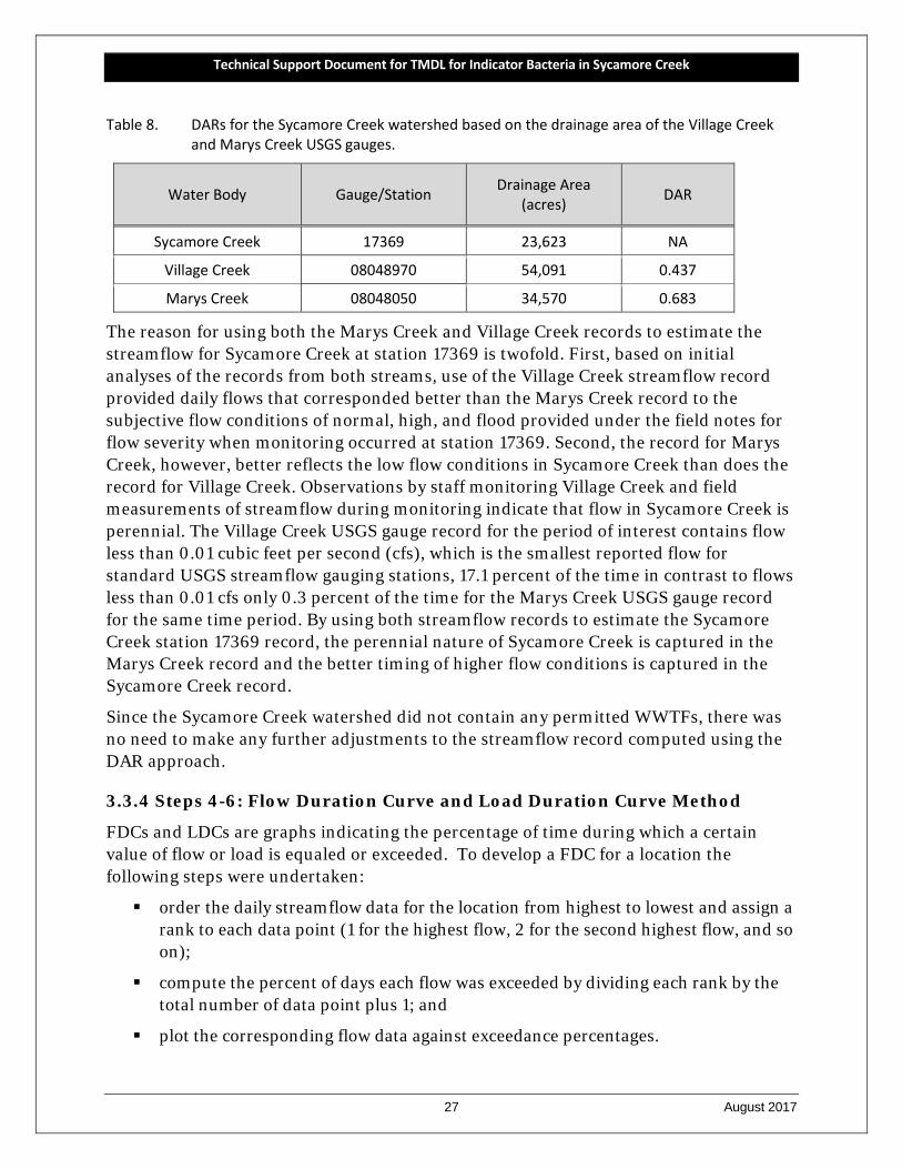
Table 8. DARs for the Sycamore Creek watershed based on the drainage area of the Village Creek and Marys Creek USGS gauges.
Water Body Gauge/Station Drainage Area (acres) DAR
Sycamore Creek 17369 23,623 NA
Village Creek 08048970 54,091 0.437
Marys Creek 08048050 34,570 0.683
The reason for using both the Marys Creek and Village Creek records to estimate the streamflow for Sycamore Creek at station 17369 is twofold. First, based on initial analyses of the records from both streams, use of the Village Creek streamflow record provided daily flows that corresponded better than the Marys Creek record to the subjective flow conditions of normal, high, and flood provided under the field notes for flow severity when monitoring occurred at station 17369. Second, the record for Marys Creek, however, better reflects the low flow conditions in Sycamore Creek than does the record for Village Creek. Observations by staff monitoring Village Creek and field measurements of streamflow during monitoring indicate that flow in Sycamore Creek is perennial. The Village Creek USGS gauge record for the period of interest contains flow less than 0.01 cubic feet per second (cfs), which is the smallest reported flow for standard USGS streamflow gauging stations, 17.1 percent of the time in contrast to flows less than 0.01 cfs only 0.3 percent of the time for the Marys Creek USGS gauge record for the same time period. By using both streamflow records to estimate the Sycamore Creek station 17369 record, the perennial nature of Sycamore Creek is captured in the Marys Creek record and the better timing of higher flow conditions is captured in the Sycamore Creek record.
Since the Sycamore Creek watershed did not contain any permitted WWTFs, there was no need to make any further adjustments to the streamflow record computed using the DAR approach.
3.3.4 Steps 4-6: Flow Duration Curve and Load Duration Curve Method
FDCs and LDCs are graphs indicating the percentage of time during which a certain value of flow or load is equaled or exceeded. To develop a FDC for a location the following steps were undertaken:
order the daily streamflow data for the location from highest to lowest and assign a rank to each data point (1 for the highest flow, 2 for the second highest flow, and so on);
compute the percent of days each flow was exceeded by dividing each rank by the total number of data point plus 1; and
plot the corresponding flow data against exceedance percentages.
Technical Support Document for TMDL for Indicator Bacteria in Sycamore Creek
28 August 2017
Further, when developing a LDC:
multiply the streamflow in cubic feet per second (cfs) by the appropriate water quality criterion for E. coli (geometric mean of 126 MPN/100 mL) and by a conversion factor (2.44658x10⁷), which gives a loading in units of MPN/day; and
plot the exceedance percentages, which are identical to the value for the streamflow data points, against geometric mean criterion of E. coli.
The resulting curve represents the maximum allowable daily loadings for the geometric mean criterion. The next step was to plot the sampled E. coli data, when such data existed at the LDC locations, on the developed LDC using the following two steps:
using the unique data for the monitoring station, compute the daily loads for each sample by multiplying the measured E. coli concentrations on a particular day by the corresponding streamflow on that day and the conversion factor (2.44658x10⁷); and
plot on the LDC the load for each measurement at the exceedance percentage for its corresponding streamflow.
The plots of the LDC with the measured loads (E. coli concentration multiplied by the daily streamflow) display the frequency and magnitude that measured loads exceed the maximum allowable loadings for the geometric mean criterion. Measured loads that are above a maximum allowable loading curve indicate an exceedance of the water quality criterion, while those below a curve show compliance.
3.4: Flow Duration Curve for Sampling Station 17369
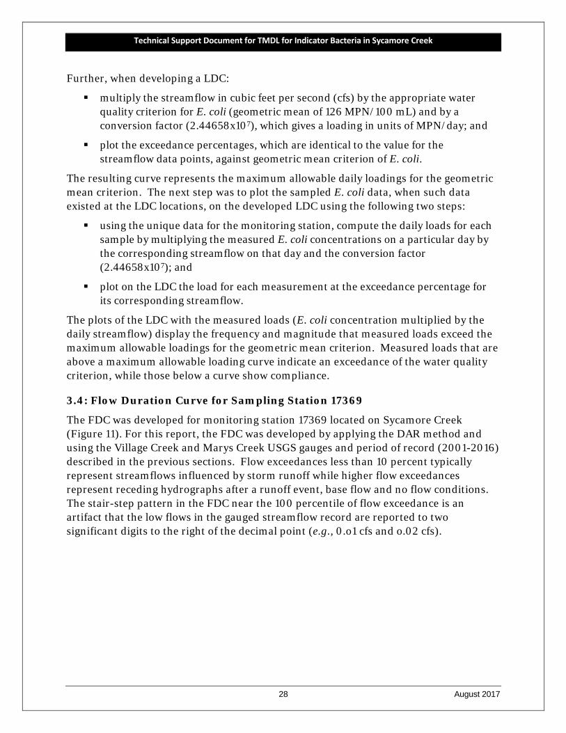
The FDC was developed for monitoring station 17369 located on Sycamore Creek (Figure 11). For this report, the FDC was developed by applying the DAR method and using the Village Creek and Marys Creek USGS gauges and period of record (2001-2016) described in the previous sections. Flow exceedances less than 10 percent typically represent streamflows influenced by storm runoff while higher flow exceedances represent receding hydrographs after a runoff event, base flow and no flow conditions. The stair-step pattern in the FDC near the 100 percentile of flow exceedance is an artifact that the low flows in the gauged streamflow record are reported to two significant digits to the right of the decimal point (e.g., 0.o1 cfs and o.02 cfs).
Technical Support Document for TMDL for Indicator Bacteria in Sycamore Creek
29 August 2017
Figure 11. Flow duration curve for Sycamore Creek (station 17369).
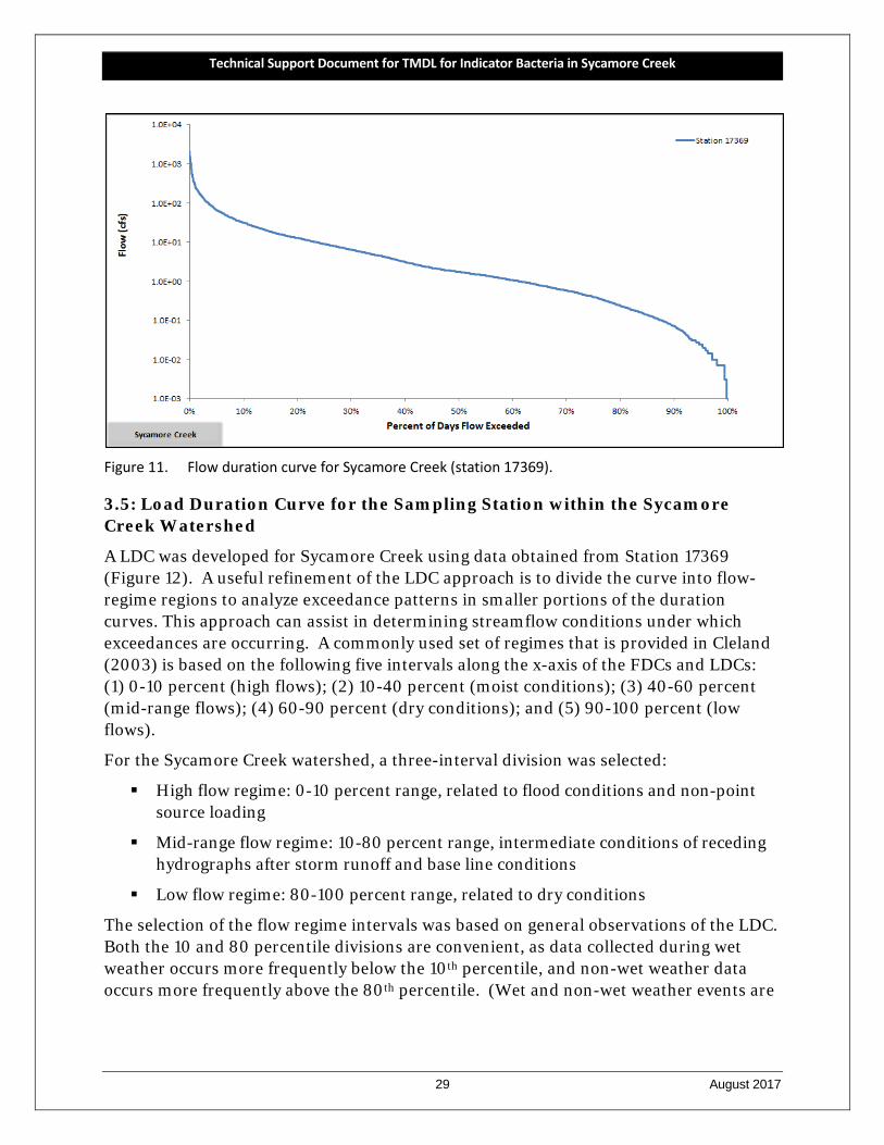
3.5: Load Duration Curve for the Sampling Station within the Sycamore Creek Watershed
A LDC was developed for Sycamore Creek using data obtained from Station 17369 (Figure 12). A useful refinement of the LDC approach is to divide the curve into flow-regime regions to analyze exceedance patterns in smaller portions of the duration curves. This approach can assist in determining streamflow conditions under which exceedances are occurring. A commonly used set of regimes that is provided in Cleland (2003) is based on the following five intervals along the x-axis of the FDCs and LDCs: (1) 0-10 percent (high flows); (2) 10-40 percent (moist conditions); (3) 40-60 percent (mid-range flows); (4) 60-90 percent (dry conditions); and (5) 90-100 percent (low flows).
For the Sycamore Creek watershed, a three-interval division was selected:
High flow regime: 0-10 percent range, related to flood conditions and non-point source loading
Mid-range flow regime: 10-80 percent range, intermediate conditions of receding hydrographs after storm runoff and base line conditions
Low flow regime: 80-100 percent range, related to dry conditions
The selection of the flow regime intervals was based on general observations of the LDC. Both the 10 and 80 percentile divisions are convenient, as data collected during wet weather occurs more frequently below the 10th percentile, and non-wet weather data occurs more frequently above the 80th percentile. (Wet and non-wet weather events are
Technical Support Document for TMDL for Indicator Bacteria in Sycamore Creek
30 August 2017
defined in the next section.) Additionally, for the high flow regime, the 0-10 percent range generally represents the steepest portion of the LDC.
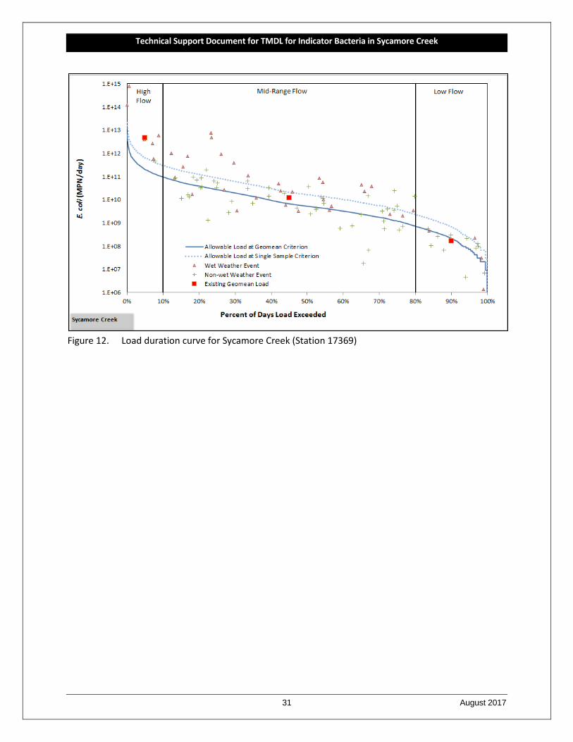
The LDC with these three flow regimes for station 17369 is provided in Figure 12, and was constructed for developing the TMDL allocation for the Sycamore Creek watershed. Geometric mean loadings for the data points within each flow regime have also been distinguished on each figure to aid interpretation. The LDC for water quality monitoring station 17369 provides a means of identifying the streamflow conditions under which exceedances in E. coli concentrations have occurred. The LDC depicts the allowable loadings at the station under the geometric mean criterion (126 MPN/100 mL) and show that existing loadings often exceed the criterion. In addition, the LDC also presents the allowable loading at the station under the single sample criterion (399 MPN/100 mL).
On the graph the measured E. coli data are presented as associated with a “wet weather event” or a “non-wet weather event.” A sample was determined to be influenced by a wet weather event based on the reported “days since last precipitation” (DSLP) as noted on field data sheets associated with each sampling event. DSLP (TCEQ water quality parameter code 72053) is a field parameter that may be noted during a sampling event to inform of the general climatic and hydrologic conditions. For station 17369 a DSLP ≤ 2 days was defined as a wet weather event. Note that a wet weather event can be indicated even under low flow conditions as a result of only a small runoff event during a period of very low base flow in the stream.
The E. coli event data plotted on the LDC for station 17369 in Figure 12 show a pattern indicative of a stream where nonpoint source loadings are important. The wet-weather event data are generally in greater exceedance of the geometric mean criterion allowable loading curve than are non-wet weather event data. Correspondingly, there is an increasing tendency for the E. coli event data to plot below the geometric mean criterion allowable loading curve as flows decrease, which is indicated in a left to right direction along the graph. This pattern of decreasing occurrence of exceedances in the event data are summarized by the geometric means of the existing data plotted for each of the three flow regimes as compared to the allowable load line for the geometric mean criterion. The geometric mean of high-flow regime event data is well above the allowable load line, the geometric mean of mid-range flow event data is just above the allowable load line, and the geometric mean of the low-flow event data is just below the allowable load line.
Technical Support Document for TMDL for Indicator Bacteria in Sycamore Creek
31 August 2017
Figure 12. Load duration curve for Sycamore Creek (Station 17369)
Technical Support Document for TMDL for Indicator Bacteria in Sycamore Creek
32 August 2017
SECTION 4 TMDL ALLOCATION ANALYSIS
Presented in this report section is the development of the bacteria TMDL allocation for the Sycamore Creek watershed. The tool used for developing TMDL allocations was the LDC method previously described in Section 3― Bacteria Tool Development. Endpoint identification, margin of safety, load reduction analysis, TMDL allocations, and other TMDL components are described herein.
The LDC method provided a flow-based approach to determine necessary reductions in bacteria loadings and allowable loadings within the Sycamore Creek watershed. As developed previously in this report, the LDC method uses frequency distributions to assess a bacteria criterion over the historical range of flows, providing a means to determine maximum allowable loadings and the load reduction necessary to achieve support of the primary contact recreation use.
For the purposes of this TMDL study, the Sycamore Creek watershed is considered to be the entire Sycamore Creek watershed (Segment 0806E) as shown in the overview map (Figure 1). Data from only one SWQM station (17369) is available for the Sycamore Creek watershed, therefore TMDL calculations are based on the location of SWQM station 17369.
Additionally, a drainage area ratio approach using historical streamflow gauges in the Village Creek and Marys Creek watersheds for the reference flow record was employed to estimate the daily flow for the SWQM station within the Sycamore Creek watershed.
4.1 Endpoint Identification
All TMDLs must identify a quantifiable water quality target that indicates the desired water quality condition and provides a measurable goal for the TMDL. The TMDL endpoint also serves to focus the technical work to be accomplished and as a criterion against which to evaluate future conditions. The Sycamore Creek watershed has a use of primary contact recreation, which is measured against a numeric criterion for the indicator bacteria E. coli. Indicator bacteria are not generally pathogenic and are indicative of potential viral, bacterial, and protozoan contamination originating from the feces of warm-blooded animals. The E. coli criterion to protect contact recreation in freshwater streams consists of a geometric mean concentration not to exceed 126 MPN/100 mL (TCEQ, 2010).
The endpoint for this TMDL is to maintain concentrations of E. coli below the geometric mean criterion of 126 MPN/100 mL. This endpoint is identical to the geometric mean criterion in the 2010 Surface Water Quality Standard (TCEQ, 2010).
Technical Support Document for TMDL for Indicator Bacteria in Sycamore Creek
33 August 2017
4.2 Seasonality
Seasonal variations or seasonality occur(s) when there is a cyclic pattern in streamflow and, more importantly, in water quality constituents. Federal regulations (40 CFR §130.7(c)(1)) require that TMDLs account for seasonal variation in watershed conditions and pollutant loading. Analysis of the seasonal differences in indicator bacteria concentrations were assessed by comparing E. coli concentrations obtained from 16 years (2001 – 2016) of routine monitoring collected in the warmer months (April - September) against those collected during the cooler months (October – March). Differences in E. coli concentrations obtained in warmer versus cooler months were then evaluated by performing a t-test on the natural log transformed dataset. This analysis of E.coli data indicated that there was a significant difference (α=0.05) in indicator bacteria between cool and warm weather seasons for Sycamore Creek (α=0.0391) with the warm season having the higher concentrations.
4.3 Linkage Analysis
Establishing the relationship between instream water quality and the source of loadings is an important component in developing a TMDL. It allows for the evaluation of management options that will achieve the desired endpoint. The relationship may be established through a variety of techniques.
Generally, if high bacteria concentrations are measured in a water body at low to median flow in the absence of runoff events, the main contributing sources are likely to be point sources and direct fecal material deposition into the water body. During ambient flows, these inputs to the system will increase pollutant concentrations depending on the magnitude and concentration of the sources. As flows increase in magnitude, the impact of point sources and direct deposition is typically diluted, and would therefore be a smaller part of the overall concentrations.
Bacteria load contributions from regulated and unregulated stormwater sources are greatest during runoff events. Rainfall runoff, depending upon the severity of the storm, has the capacity to carry indicator bacteria from the land surface into the receiving stream. Generally, this loading follows a pattern of lower concentrations in the water body just before the rain event, followed by a rapid increase in bacteria concentrations in the water body as the first flush of storm runoff enters the receiving stream. Over time, the concentrations decline because the sources of indicator bacteria are attenuated as runoff washes them from the land surface and the volume of runoff decrease following the rain event.
Load duration curves were used to examine the relationship between instream water quality and the source of indicator bacteria loads. Inherent to the use of LDCs as the mechanism of linkage analysis is the assumption of a one-to-one relationship between instream loadings and loadings originating from point sources and the landscape as regulated and non-regulated sources. Further this one-to-one relationship was also
Technical Support Document for TMDL for Indicator Bacteria in Sycamore Creek
34 August 2017
inherently assumed when using LDCs to define the TMDL pollutant load allocation (Section 4.7).
4.4 Load Duration Curve Analysis
A LDC method was used to examine the relationship between instream water quality, the broad sources of indicator bacteria loads, and are the basis of the TMDL allocations. The strength of this TMDL is the use of the LDC method to determine the TMDL allocations. LDCs are a simple statistical method that provides a basic description of the water quality problem. This tool is easily developed and explained to stakeholders, and uses available water quality and flow data. The LDC method does not require any assumptions regarding loading rates, stream hydrology, land use conditions, and other conditions in the watershed. The USEPA supports the use of the basic LDC approach to characterize pollutant sources. In addition, many other states are using this basic method to develop TMDLs. As discussed in more detail in Section 4.7 (Pollutant Load Allocation), the TMDL loads were based on the median flow within the high flow regime (or 5 percent flow), where exceedances of the primary contact recreation criteria are most pronounced.
The LDC method allows for estimation of existing and TMDL loads by utilizing the cumulative frequency distribution of streamflow and measured pollutant concentration data (Cleland, 2003). In addition to estimating stream loads, this method allows for the determination of the hydrologic conditions under which impairments are typically occurring, can give indications of the broad origins of the bacteria (i.e., point source and stormwater) and provides a means to allocate allowable loadings.
Based on the LDCs to be used in the pollutant load allocation process with historical E. coli data added to the graphs (Figures 12) and Section 2.7 (Potential Sources of Fecal Indicator Bacteria), the following broad linkage statements can be made. For the Sycamore Creek watershed, the historical E. coli data indicate that elevated bacteria loadings occur especially under the highest flow and mid-range flow regimes. There is generally some moderation of the elevated loadings under the lowest flow regime. Regulated stormwater comprises a majority portion of the Sycamore Creek watershed and must be considered a major contributor. Most likely unregulated stormwater comprises the minority of high flow related loadings. In some situations, elevated E. coli loadings under the lower flow conditions can be attributed to point sources such as WWTFs; however, this rational is nullified due to the absence of permitted dischargers within the Sycamore Creek watershed. Therefore, other sources of bacteria loadings under lower flows and in the absence of permitted discharger contributions (i.e., without WWTF contribution) are occurring though the sources cannot be determined through this analysis.
Technical Support Document for TMDL for Indicator Bacteria in Sycamore Creek
35 August 2017
4.5 Margin of Safety
The margin of safety (MOS) is used to account for uncertainty in the analysis performed to develop the TMDL and thus provides a higher level of assurance that the goal of the TMDL will be met. According to USEPA guidance (USEPA, 1991), the MOS can be incorporated into the TMDL using two methods:
1) Implicitly incorporating the MOS using conservative model assumptions to develop allocations; or
2) Explicitly specifying a portion of the TMDL as the MOS and using the remainder for allocations.
The MOS is designed to account for any uncertainty that may arise in specifying water quality control strategies for the complex environmental processes that affect water quality. Quantification of this uncertainty, to the extent possible, is the basis for assigning a margin of safety.
The TMDL covered by this report incorporate an explicit MOS by setting a target for indicator bacteria loads that is 5 percent lower than the geometric mean criterion. For primary contact recreation, this equates to a geometric mean target for E. coli of 119.7 MPN/100 mL. The net effect of the TMDL with MOS is that the assimilative capacity or allowable pollutant loading of each water body is slightly reduced.
4.6 Load Reduction Analysis
While the TMDL for the Sycamore Creek watershed was developed using LDC and associated load allocations, additional insight may, in certain situations, be gained through a load reduction analysis. A single percent load reduction required to meet the allowable loading for each of the three flow regimes was determined using the historical E. coli data obtained from the monitoring station within the impaired water body.
For each flow regime the percent reduction required to achieve the geometric mean criterion was determined by calculating the difference in the existing (or measured) geometric mean concentration and the 126MPN/100 mL criterion and dividing that difference by the existing geometric mean concentration (Table 9).
Table 9. Percent reduction calculations for Sycamore Creek station 17369. Segment 0806E.
Flow Regime Number of Samples Geometric Mean by Flow
Regime (MPN/100 mL)
Percent Reduction by Flow Regime
High Flows (0-10%) 7 2,945 95.7%
Mid-Range Flow (10-80%) 75 230 45.2%
Low Flows (80-100%) 15 99 0%
Technical Support Document for TMDL for Indicator Bacteria in Sycamore Creek
36 August 2017
4.7. Pollutant Load Allocation
The bacteria TMDL for Sycamore Creek (Segment 0806E) was developed as a pollutant load allocation based on information from the LDC for Sycamore Creek monitoring station 17369 (Figure 12). As discussed in more detail in Section 3, the bacteria LDC was developed by multiplying each flow value along the flow duration curve by the E. coli criterion (126 MPN/100 mL) and by the conversion factor used to represent maximum loading in MPN/day. Effectively, the “Allowable Load” displayed in the LDC at 5 percent exceedance (the median value of the high-flow regime) is the TMDL:
TMDL (MPN/day) = Criterion * Flow (cfs) * Conversion Factor (Eq. 1) Where:
Criterion = 126 MPN/100 mL (E. coli) Conversion Factor (to MPN/day) = 283.1685 100 mL/ft3 * 86,400 sec/day
4.7.1 Definition of TMDL Components
A TMDL represents the maximum amount of a pollutant that the water body can receive in a single day without exceeding water quality standards. The pollutant load allocations for the selected scenarios were calculated using the following basic equation:
TMDL = WLA + LA + FG + MOS (Eq. 2)
Where:
TMDL = total maximum daily load
WLA = waste load allocation, the amount of pollutant allowed by existing regulated or permitted dischargers
LA = load allocation, the amount of pollutant allowed by unregulated or non-permitted sources
FG = loadings associated with future growth from potential permitted facilities
MOS = margin of safety
As stated in 40 CFR, §130.2(1), TMDLs can be expressed in terms of mass per time, toxicity, or other appropriate measures. For E. coli, TMDLs are expressed as MPN/day, and represent the maximum one-day load the stream can assimilate while still attaining the standards for surface water quality.
The TMDL components for the Sycamore Creek watershed covered in this report are derived using the median flow within the high flow regime (or 5 percent flow) of the LDC developed for SWQM station 17369.
The margin of safety is only applied to the allowable loading for a watershed. Therefore the margin of safety is expressed mathematically as the following:
MOS = 0.05 * TMDL (Eq. 3)
Technical Support Document for TMDL for Indicator Bacteria in Sycamore Creek
37 August 2017
Where:
MOS = margin of safety load
TMDL = total maximum allowable load
The Waste Load Allocation (WLA) consists of two parts – the waste load that is allocated to TPDES-regulated wastewater treatment facilities (WLAWWTF) and the waste load that is allocated to regulated stormwater dischargers (WLASW).
WLA = WLAWWTF + WLASW (Eq. 4)
TPDES-permitted wastewater treatment facilities are allocated a daily waste load (WLAWWTF) calculated as their full permitted discharge flow rate multiplied by one half the instream geometric criterion. One-half of the water quality criterion (63 MPN/100mL) is used as the WWTF target to provide instream and downstream load capacity. Thus WLAWWTF is expressed in the following equation:
WLAWWTF = Target * Flow * Conversion Factor (Eq. 5) Where:
Target= 63 MPN/100 mL Flow = full permitted flow (MGD) Conversion Factor (to MPN/day) = 1.54723 cfs/MGD *283.1685 100 mL/ft3 *
86,400 s/d
Due to the absence of any permitted dischargers in the Sycamore Creek watershed, the WLAWWTF component is zero.
Stormwater discharges from MS4, industrial, and construction areas are also considered permitted or regulated point sources. Therefore, the WLA calculations must also include an allocation for permitted stormwater discharges (WLASW). A simplified approach for estimating the WLA for these areas was used in the development of these TMDLs due to the limited amount of data available, the complexities associated with simulating rainfall runoff, and the variability of stormwater loading. The percentage of the land area included in the Sycamore Creek watershed that is under the jurisdiction of stormwater permits is used to estimate the amount of the overall runoff load that should be allocated as the permitted stormwater contribution in the WLASW component of the TMDL.
WLASW is the sum of loads from regulated stormwater sources and is calculated as follows:
WLASW = (TMDL – WLAWWTF – FG – MOS) * FDASWP (Eq. 6)
Where: WLASW = sum of all regulated stormwater loads
TMDL = total maximum daily load
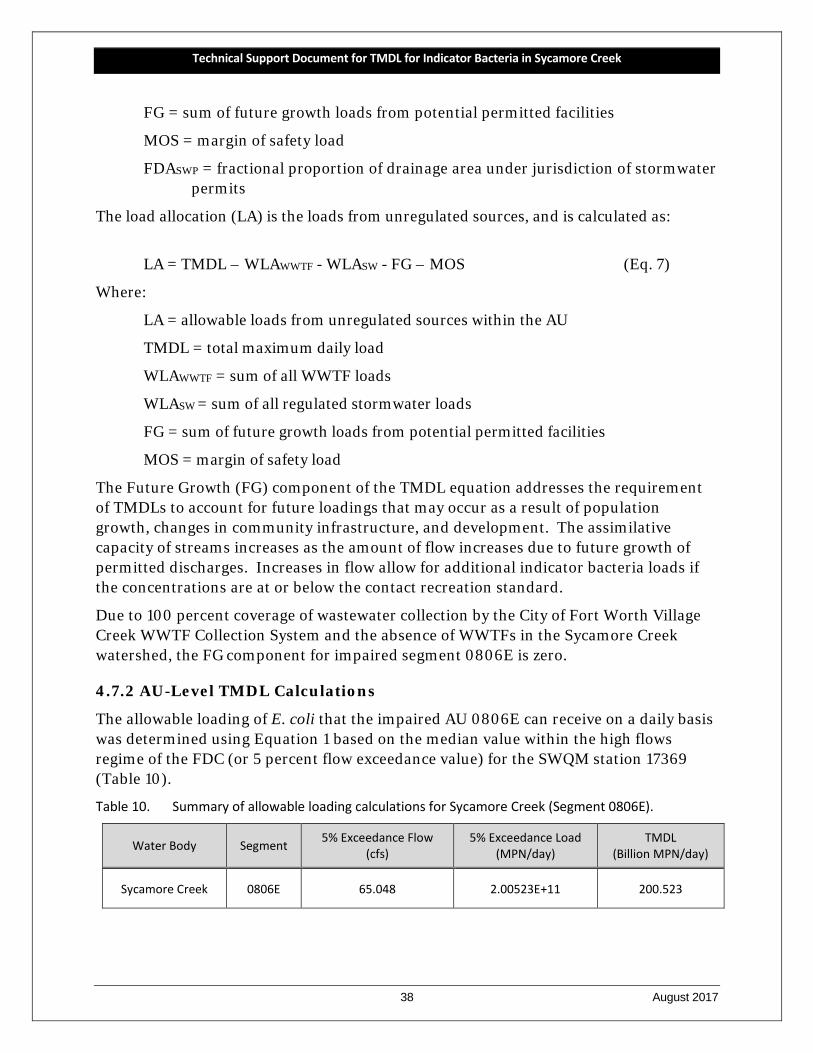
Technical Support Document for TMDL for Indicator Bacteria in Sycamore Creek
38 August 2017
FG = sum of future growth loads from potential permitted facilities
MOS = margin of safety load
FDASWP = fractional proportion of drainage area under jurisdiction of stormwater permits
The load allocation (LA) is the loads from unregulated sources, and is calculated as:
LA = TMDL – WLAWWTF - WLASW - FG – MOS (Eq. 7)
Where:
LA = allowable loads from unregulated sources within the AU
TMDL = total maximum daily load
WLAWWTF = sum of all WWTF loads
WLASW = sum of all regulated stormwater loads
FG = sum of future growth loads from potential permitted facilities
MOS = margin of safety load
The Future Growth (FG) component of the TMDL equation addresses the requirement of TMDLs to account for future loadings that may occur as a result of population growth, changes in community infrastructure, and development. The assimilative capacity of streams increases as the amount of flow increases due to future growth of permitted discharges. Increases in flow allow for additional indicator bacteria loads if the concentrations are at or below the contact recreation standard.
Due to 100 percent coverage of wastewater collection by the City of Fort Worth Village Creek WWTF Collection System and the absence of WWTFs in the Sycamore Creek watershed, the FG component for impaired segment 0806E is zero.
4.7.2 AU-Level TMDL Calculations
The allowable loading of E. coli that the impaired AU 0806E can receive on a daily basis was determined using Equation 1 based on the median value within the high flows regime of the FDC (or 5 percent flow exceedance value) for the SWQM station 17369 (Table 10).
Table 10. Summary of allowable loading calculations for Sycamore Creek (Segment 0806E).
Water Body Segment 5% Exceedance Flow (cfs)
5% Exceedance Load (MPN/day)
TMDL (Billion MPN/day)
Sycamore Creek 0806E 65.048 2.00523E+11 200.523
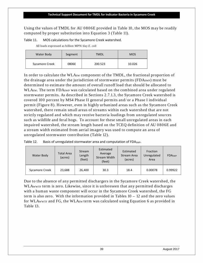
Technical Support Document for TMDL for Indicator Bacteria in Sycamore Creek
39 August 2017
Using the values of TMDL for AU 0806E provided in Table 10, the MOS may be readily computed by proper substitution into Equation 3 (Table 11).
Table 11. MOS calculations for the Sycamore Creek watershed. All loads expressed as billion MPN/day E. coli
Water Body Segment TMDL MOS
Sycamore Creek 0806E 200.523 10.026
In order to calculate the WLASW component of the TMDL, the fractional proportion of the drainage area under the jurisdiction of stormwater permits (FDASWP) must be determined to estimate the amount of overall runoff load that should be allocated to WLASW. The term FDASWP was calculated based on the combined area under regulated stormwater permits. As described in Sections 2.7.1.3, the Sycamore Creek watershed is covered 100 percent by MS4 Phase II general permits and/or a Phase I individual permit (Figure 8). However, even in highly urbanized areas such as the Sycamore Creek watershed, there remain small areas of streams within each watershed that are not strictly regulated and which may receive bacteria loadings from unregulated sources such as wildlife and feral hogs. To account for these small unregulated areas in each impaired watershed, the stream length based on the TCEQ definition of AU 0806E and a stream width estimated from aerial imagery was used to compute an area of unregulated stormwater contribution (Table 12).
Table 12. Basis of unregulated stormwater area and computation of FDASWP.
Water Body Total Area (acres)
Stream Length (feet)
Estimated Average
Stream Width (feet)
Estimated Stream Area
(acres)
Fraction Unregulated
Area FDASWP
Sycamore Creek 23,688 26,400 30.3 18.4 0.00078 0.99922
Due to the absence of any permitted dischargers in the Sycamore Creek watershed, the WLAWWTF term is zero. Likewise, since it is unforeseen that any permitted discharges with a human waste component will occur in the Sycamore Creek watershed, the FG term is also zero. With the information provided in Tables 10 – 12 and the zero values for WLAWWTF and FG, the WLASW term was calculated using Equation 6 as provided in Table 13.
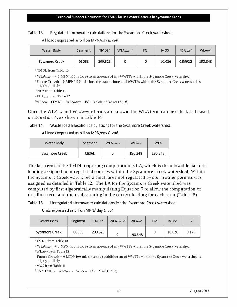
Technical Support Document for TMDL for Indicator Bacteria in Sycamore Creek
40 August 2017
Table 13. Regulated stormwater calculations for the Sycamore Creek watershed.
All loads expressed as billion MPN/day E. coli
Water Body Segment TMDLa WLAWWTFb FGc MOSd FDASWPe WLASWf
Sycamore Creek 0806E 200.523 0 0 10.026 0.99922 190.348
a. TMDL from Table 10 b WLAWWTF = 0 MPN/100 mL due to an absence of any WWTFs within the Sycamore Creek watershed c Future Growth = 0 MPN/100 mL since the establishment of WWTFs within the Sycamore Creek watershed is
highly unlikely d.MOS from Table 11 e FDASWP from Table 12 f WLASW = (TMDL – WLAWWTF – FG – MOS) * FDASWP (Eq. 6)
Once the WLASW and WLAWWTF terms are known, the WLA term can be calculated based on Equation 4, as shown in Table 14
Table 14. Waste load allocation calculations for the Sycamore Creek watershed.
All loads expressed as billion MPN/day E. coli
Water Body Segment WLAWWTF WLASW WLA
Sycamore Creek 0806E 0 190.348 190.348
The last term in the TMDL requiring computation is LA, which is the allowable bacteria loading assigned to unregulated sources within the Sycamore Creek watershed. Within the Sycamore Creek watershed a small area not regulated by stormwater permits was assigned as detailed in Table 12. The LA for the Sycamore Creek watershed was computed by first algebraically manipulating Equation 7 to allow the computation of this final term and then substituting in the correct loading for each term (Table 15).
Table 15. Unregulated stormwater calculations for the Sycamore Creek watershed.
Units expressed as billion MPN/ day E. coli
Water Body Segment TMDLa WLAWWTFb WLASWc FGd MOSe LAf
Sycamore Creek 0806E 200.523 0 190.348
0 10.026 0.149
a TMDL from Table 10 b WLAWWTF = 0 MPN/100 mL due to an absence of any WWTFs within the Sycamore Creek watershed c.WLASW from Table 13 d Future Growth = 0 MPN/100 mL since the establishment of WWTFs within the Sycamore Creek watershed is
highly unlikely e.MOS from Table 11 f LA = TMDL – WLAWWTF - WLASW - FG – MOS (Eq. 7)
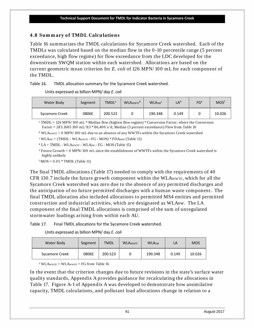
Technical Support Document for TMDL for Indicator Bacteria in Sycamore Creek
41 August 2017
4.8 Summary of TMDL Calculations
Table 16 summarizes the TMDL calculations for Sycamore Creek watershed. Each of the TMDLs was calculated based on the median flow in the 0-10 percentile range (5 percent exceedance, high flow regime) for flow exceedance from the LDC developed for the downstream SWQM station within each watershed. Allocations are based on the current geometric mean criterion for E. coli of 126 MPN/100 mL for each component of the TMDL.
Table 16. TMDL allocation summary for the Sycamore Creek watershed.
Units expressed as billion MPN/ day E. coli
Water Body Segment TMDLa WLAWWTFb WLASWc LAd FGe MOSf
Sycamore Creek 0806E 200.523 0 190.348 0.149 0 10.026
a TMDL = 126 MPN/100 mL * Median flow (highest flow regime) * Conversion Factor; where the Conversion Factor = 283.1685 100 mL/ft3 * 86,400 s/d; Median (5 percent exceedance) Flow from Table 10
b WLAWWTF = 0 MPN/100 mL due to an absence of any WWTFs within the Sycamore Creek watershed c WLASW = (TMDL - WLAWWTF - FG - MOS) * FDASWP (Table 13) d LA = TMDL - WLAWWTF - WLASW - FG - MOS (Table 15) e Future Growth = 0 MPN/100 mL since the establishment of WWTFs within the Sycamore Creek watershed is
highly unlikely f MOS = 0.05 * TMDL (Table 11)
The final TMDL allocations (Table 17) needed to comply with the requirements of 40 CFR 130.7 include the future growth component within the WLAWWTF, which for all the Sycamore Creek watershed was zero due to the absence of any permitted discharges and the anticipation of no future permitted discharges with a human waste component. The final TMDL allocation also included allocations to permitted MS4 entities and permitted construction and industrial activities, which are designated as WLAsw. The LA component of the final TMDL allocations is comprised of the sum of unregulated stormwater loadings arising from within each AU.
Table 17. Final TMDL allocations for the Sycamore Creek watershed.
Units expressed as billion MPN/ day E. coli
Water Body Segment TMDL WLAWWTF WLASW LA MOS
Sycamore Creek 0806E 200.523 0 190.348 0.149 10.026
a WLAWWTF = WLAWWTF + FG from Table 16
In the event that the criterion changes due to future revisions in the state’s surface water quality standards, Appendix A provides guidance for recalculating the allocations in Table 17. Figure A-1 of Appendix A was developed to demonstrate how assimilative capacity, TMDL calculations, and pollutant load allocations change in relation to a

Technical Support Document for TMDL for Indicator Bacteria in Sycamore Creek
42 August 2017
number of proposed water quality criteria for E. coli. The equations provided, along with Figure A-1 allow calculation of new TMDLs and pollutant load allocations based on any potential new water quality criterion for E. coli.
Technical Support Document for TMDL for Indicator Bacteria in Sycamore Creek
43 August 2017
Section 5
REFERENCES
AMVA (American Veterinary Medical Association) 2015, 2012 U.S. Pet Ownership Statistics, retrieved Jul 14, 2017 from website: <www.avma.org/KB/Resources/Statistics/Pages/Market-research-statistics-US-pet-ownership.aspx>
Asquith, W.H., Roussel, M.C., Vrabel, J. 2006. Statewide analysis of the drainage area ratio method for 34 streamflow percentile ranges in Texas. US Geological Survey Scientific Investigative Report 2006-5286
Cleland, B. 2003. TMDL Development From the “Bottom Up” - Part III: Duration Curves and Wet-Weather Assessments. Retrieved July 27, 2017, from <engineering.purdue.edu/mapserve/ldc/pldc/help/TMDL_Development_from_the_Bottom_UP_PartIV.pdf >
Fort Worth 2017a. Sanitary Sewer Overflows shapefile for incidences that occurred from Jan. 2009 through December 2016. Received by email on February 2, 2017.
Fort Worth 2017b. Onsite Sewage Facility data for Tarrant County from 2000 to 2017. Received by email on June 26, 2017.
Jones, C. A., Wagner, K., Di Giovanni, G., Hauck, L., Mott, J., Rifai, H., Srinivasan, R., Ward, G., Wythe, K. 2009. Bacteria Total Maximum Daily Load Task Force Final Report (No. TR-341). TWRI. Retrieved July 29, 2017, from <twri.tamu.edu/reports/2009/tr341.pdf>
NEIWPCC (New England Interstate Water Pollution Control Commission). 2003. Illicit Discharge Detection and Elimination Manual.
NCTCOG (North Central Texas Council of Governments). 2013a. 2010 Land Use. Retrieved Dec 2014, from Regional Data Center: <rdc.nctcog.org/Members/ServiceGroup.aspx?id=9>
NCTCOG (North Central Texas Council of Governments). 2013b. WWTF shapefile. Retrieved Feb 3, 2015, from NCTCOG ftp link : < https://filehouse.nctcog.org/index.php?action=Authenticate.login&cookies_enabled=1&login=1&js_enabled=yes&username=jRVOC74b_aukNb7T9BJk4A>
NCTCOG (North Central Texas Council of Governments). 2015. Traffic Survey Zones. Retrieved Jul 19, 2017, from Regional Data Center: <rdc.nctcog.org/Members/ServiceGroup.aspx?id=5&prodid=241>
NDEP (Nevada Division of Environmental Protection). 2003. Load Duration Curve Methodology for Assessment and TMDL Development. Retrieved May 23, 2013, from <ndep.nv.gov/uploads/water-tmdl-docs/LOADCURV.PDF >
NOAA (National Oceanic and Atmospheric Administration). 2009. Dallas/Fort Worth Climate Narrative. Retrieved Jul, 2017, from National Weather Service Forecast Office: <www.srh.noaa.gov/fwd/?n=dnarrative>
NOAA (National Oceanic and Atmospheric Administration). 2017. Station USW00013961,Fort Worth Meacham Field, TX, US Retrieved Jul, 2017, from National Climatic Data Center: <www.ncdc.noaa.gov/cdo-web/search>
Technical Support Document for TMDL for Indicator Bacteria in Sycamore Creek
44 August 2017
NRCS (Natural Resources Conservation Service). 2007. Part 630 Hydrology Chapter 7 Hydrologic Soil Groups. Retrieved August 3, 2017, from <directives.sc.egov.usda.gov/OpenNonWebContent.aspx?content=17757.wba>
NRCS (Natural Resources Conservation Service). 2015. Soil Survey Geographic Database (SSURGO) for Tarrant County. Retrieved Jul 17, 2017 from <gdg.sc.egov.usda.gov/>
TCEQ. (Texas Commission on Environmental Quality). 2010. 2010 Texas Surface Water Quality Standards. Final 2010 Chapter 307 Rule Amendment. Retrieved, July 29, 2017. <www.tceq.texas.gov/waterquality/standards/2010standards.html>
TCEQ (Texas Commission on Environmental Quality). 2011a. Two Total Maximum Daily Loads for Indicator Bacteria in Cottonwood Branch and Grapevine Creek. Retrieved July 29, 2017 from <www.tceq.texas.gov/assets/public/waterquality/tmdl/66trinitybact/66a-CottonGrapeAdoptedSept2011.pdf>
TCEQ (Texas Commission on Environmental Quality). 2011b. Two Total Maximum Daily Loads for Indicator Bacteria in the Upper Trinity River, Dallas, Texas. Retrieved July 29, 2017 from <www.tceq.texas.gov/assets/public/waterquality/tmdl/66trinitybact/66-trinitybacteria-adopted.pdf>
TCEQ (Texas Commission on Environmental Quality). 2013. Thirteen Total Maximum Daily Loads for Indicator Bacteria in the Lower West Fork Trinity River Watershed. Retrieved July 29, 2017 from <www.tceq.texas.gov/assets/public/waterquality/tmdl/66trinitybact/66d-adopted-LowerWestForkTrinityBacteria.pdf>
TCEQ. (Texas Commission on Environmental Quality) 2015. 2014 Texas Integrated Report of Surface Water Quality for the Clean Water Act Sections 305(b) and 303(d). Retrieved July 25, 2016. <www.tceq.texas.gov/waterquality/assessment/14twqi/14txir>
TCEQ (Texas Commission on Environmental Quality). 2016. Four Total Maximum Daily Loads for Indicator Bacteria in the Cottonwood Creek, Fish Creek, Kirby Creek, and Crockett Branch Upstream of Mountain Lake Creek. Retrieved July 29, 2017 from <www.tceq.texas.gov/assets/public/waterquality/tmdl/66trinitybact/66F-MtCreekLakeTMDL-Adopted.pdf>
TCEQ (Texas Commission on Environmental Quality). 2017. Central Registry Query. Retrieved Aug. 2017, from < www15.tceq.texas.gov/crpub/index.cfm?fuseaction=home.welcome >
TIAER (Texas Institute for Applied Environmental Research). 2016. Support for Total Maximum Daily Load (TMDL) for Indicator Bacteria for Sycamore Creek: Quality Assurance Project Plan for Existing Data Revision #0 and Subsequent Revision and Amendments. Initially approved by TCEQ November 29, 2016.
USCB (United States Census Bureau). 2014. 2010 Census Block Shapefiles for Dallas and Tarrant County. Retrieved Oct 17, 2014 : www.census.gov/cgi-bin/geo/shapefiles2010/main >; Tabular data from: 2010 Census Block Households and Families. Retrieved Feb 5, 2015, from American FactFinder: < factfinder.census.gov/faces/nav/jsf/pages/index.xhtml >
USCB (United States Census Bureau). 2017. 2010 Urban Areas Shapefile. Retrieved April 23, 2017 : www.census.gov/geo/maps-data/data/cbf/cbf_ua.html >
USEPA (United States Environmental Protection Agency). 1991. Guidance for Water Quality-Based Decisions: The TMDL Process. Retrieved July 27, 2017, from Office of Water:
Technical Support Document for TMDL for Indicator Bacteria in Sycamore Creek
45 August 2017
Total Maximum Daily Loads (303d): <water.epa.gov/lawsregs/lawsguidance/cwa/tmdl/decisions_index.cfm>
USEPA (United States Environmental Protection Agency). 2013. Basic Information about Pathogens and Indicators in Drinking Water. Retrieved Aug 4, 2015, from Water: Basic Information about Regulated Drinking Water Contaminants: <water.epa.gov/drink/contaminants/basicinformation/pathogens.cfm>
USGS (United States Geological Survey). 2017. USGS Streamflow Data for Station 08048900, Village Creek at Everman, TX and Station 08047050, Marys Creek at Benbrook, TX. Retrieved March 9, 2017, from .0waterdata.usgs.gov/tx/nwis/rt >
Technical Support Document for TMDL for Indicator Bacteria in Sycamore Creek
46 August 2017
APPENDIX A
EQUATIONS FOR CALCULATING TMDL ALLOCATIONS FOR CHANGED CONTACT RECREATION STANDARD
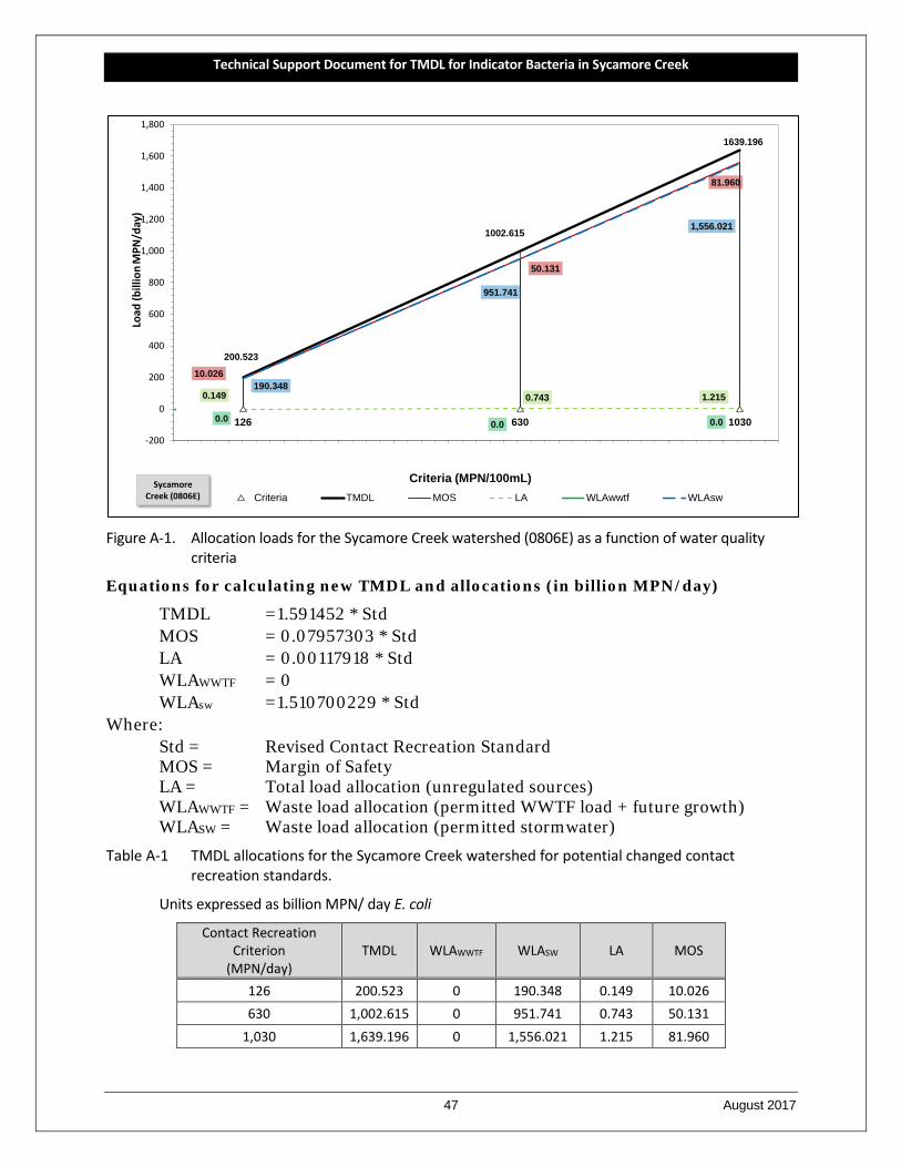
Technical Support Document for TMDL for Indicator Bacteria in Sycamore Creek
47 August 2017
Figure A-1. Allocation loads for the Sycamore Creek watershed (0806E) as a function of water quality
criteria
Equations for calculating new TMDL and allocations (in billion MPN/day)
TMDL =1.591452 * Std MOS = 0.07957303 * Std LA = 0.00117918 * Std WLAWWTF = 0 WLAsw =1.510700229 * Std Where:
Std = Revised Contact Recreation Standard MOS = Margin of Safety LA = Total load allocation (unregulated sources) WLAWWTF = Waste load allocation (permitted WWTF load + future growth)
WLASW = Waste load allocation (permitted stormwater)
Table A-1 TMDL allocations for the Sycamore Creek watershed for potential changed contact recreation standards.
Units expressed as billion MPN/ day E. coli
Contact Recreation Criterion
(MPN/day) TMDL WLAWWTF WLASW LA MOS
126 200.523 0 190.348 0.149 10.026 630 1,002.615 0 951.741 0.743 50.131
1,030 1,639.196 0 1,556.021 1.215 81.960
126 630 1030
200.523
1002.615
1639.196
10.026
50.131
81.960
0.149 0.743 1.215
0.00.0 0.0
190.348
951.741
1,556.021
-200
0
200
400
600
800
1,000
1,200
1,400
1,600
1,800Lo
ad (b
illio
nM
PN/d
ay)
Criteria (MPN/100mL)Criteria TMDL MOS LA WLAwwtf WLAsw
Sycamore Creek (0806E)