Embed Size (px)
Citation preview
-1-
Before you begin, read these instructions twice and check to be sure all parts and tools are accounted for. Please retain these installation instructions for future reference and parts ordering information.
P/N 2879833550 INDY ELECTRIC START KIT
Application All 550 INDY
Kit Contents: Qty Part Description Part Number 1 Asm-Stud Plate 1017181 1 Weld-Battery Box 1017182 1 Asm-Stud Plate 60.96 mm 1017255 1 Asm-Bracket, Battery Box Front 1018527 1 Asm-Ring Gear/Sheave, CVT 2205423 1 Harness-ES DC-SDI 2411513 1 Breaker-Circuit 12 Amp 2411592 1 Asm-Starter 2412235 1 Asm-Cable, Battery/Switch Magnetic 2412523 1 Jumper-Stubber, E/R W/ E. S. 2461060 1 Cable -Blk (Battery/Engine) 4011546 1 Switch-Magnetic 4012358 1 Cable 1045 mm 6 GA Red 4013289 2 Hook- “D” 5224468 1 Shield-Heat Battery 5253414 1 Bracket-Starter, Rear, Plated 5257395 1 Bracket-Starter, Front, Plated 5257396 1 Strap-Rubber 5410608 5 Panduit Strap (Tie Strap) 7080138 1 Clip-Routing 7081496 2 Screw-3/8-16x1-HX HD CP-GR5-Y 7512492 2 Screw-M8x1.25x20-HX/SOC/SEMS-Y 7516730 2 Screw-M6x1.0x15 HX/CP/SEMS-Y 7516815 2 Screw-HXFL-M6x1.0x16 8.8 ZY3 7518548 1 Screw-M8X1.25X30 8.8 TR/TX ZOD 7518953 1 Screw-HXFL-M8x1.25x25 8.8 ZODP 30 7519243 1 Nut-1/4-20 Hex-Y 7542105 4 Nut-1/4-20 Nyloc Flanged-Y 7542153 1 Nut-M8X1.25, Flg, Nyloc-Olive D 7547332 4 Nut-M6x1.0, Flg, Nyloc-Olive D 7547339 2 Washer-3/8 Spring-Lock-MED-Y 7552603 1 Washer-1/4 Spring Lock-Y 7552801 1 Instructions 9925037
-2-
Parts and Tools Required: Battery (PN 4013045) Spring Puller Drive Clutch Puller, PB50, (PN PS-51183) Flat Screwdriver Drive Clutch holding Tool, PB50, (PN PS-51184) #40 Torx Socket Standard Socket Set Metric Socket Set Standard Wrench Set Metric Wrench Set Torque Wrench (0-75 ft. lbs.) Side Cutter Large Phillips Screwdriver Masking Tape or Duct Tape 6 mm Allen Wrench 6 mm Ball End Allen Socket, 3” Long 8 mm Allen Socket 1 7/16 Socket 22 mm or 7/8 Socket Master Repair Manual (MRM)
IMPORTANT: For your safety, and to ensure a satisfactory installation, perform all installation steps correctly in the sequence as shown on the attached instructions.
WARNING: Battery electrolyte contains sulfuric acid and is poisonous! Serious burns can result from contact with the skin, eyes, or clothing. Avoid contact with electrolyte.
IMPORTANT: Perform all items correctly and completely.
INSTALLATION INSTRUCTIONS:
1. Charge the battery per instructions included with the battery.
2. Verify the unit is not in reverse. NOTE: Driven will not open and belt removal is not possible if stopped in reverse mode.
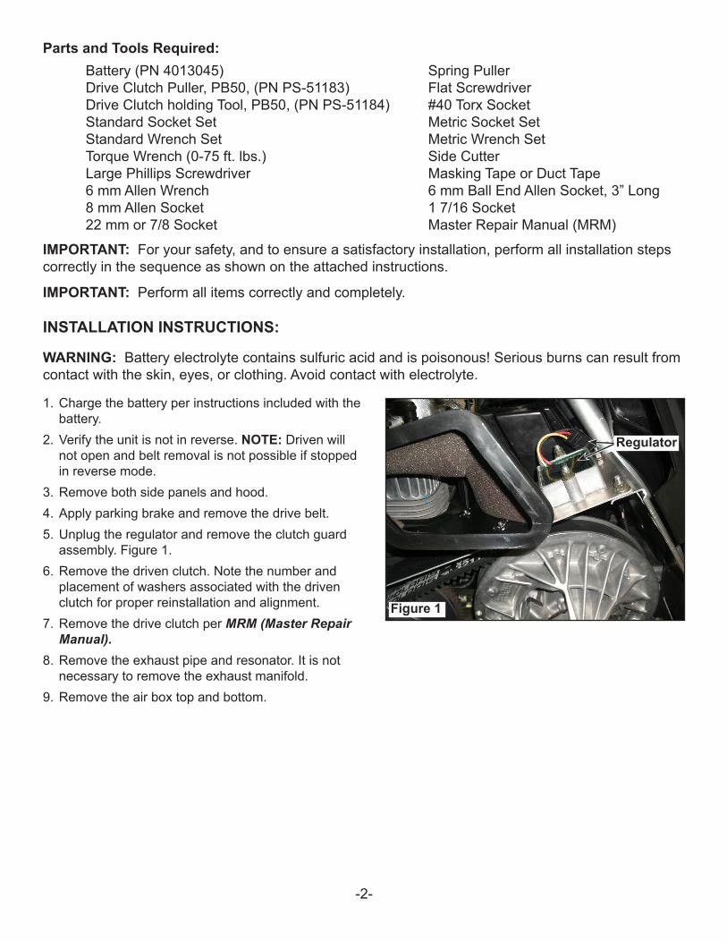
3. Remove both side panels and hood.4. Apply parking brake and remove the drive belt.5. Unplug the regulator and remove the clutch guard
assembly. Figure 1.6. Remove the driven clutch. Note the number and
placement of washers associated with the driven clutch for proper reinstallation and alignment.
7. Remove the drive clutch per MRM (Master Repair Manual).
8. Remove the exhaust pipe and resonator. It is not necessary to remove the exhaust manifold.
9. Remove the air box top and bottom.
Figure 1
Regulator
-3-
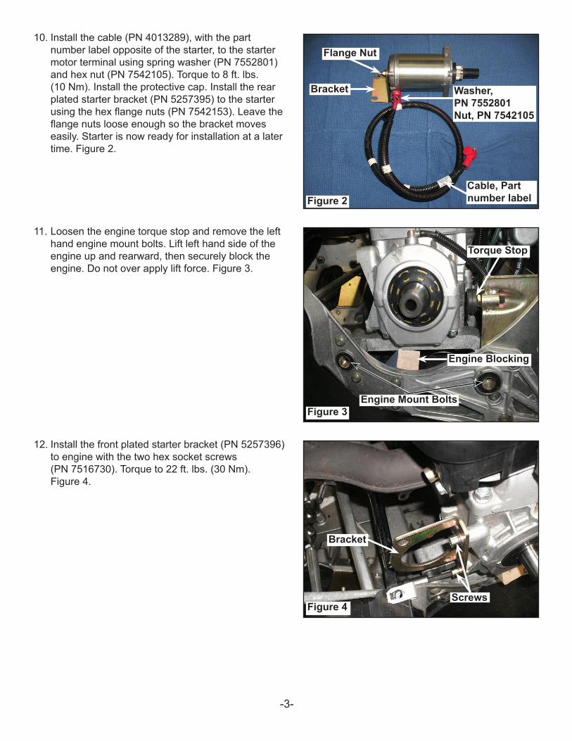
10. Install the cable (PN 4013289), with the part number label opposite of the starter, to the starter motor terminal using spring washer (PN 7552801) and hex nut (PN 7542105). Torque to 8 ft. lbs. (10 Nm). Install the protective cap. Install the rear plated starter bracket (PN 5257395) to the starter using the hex flange nuts (PN 7542153). Leave the flange nuts loose enough so the bracket moves easily. Starter is now ready for installation at a later time. Figure 2.
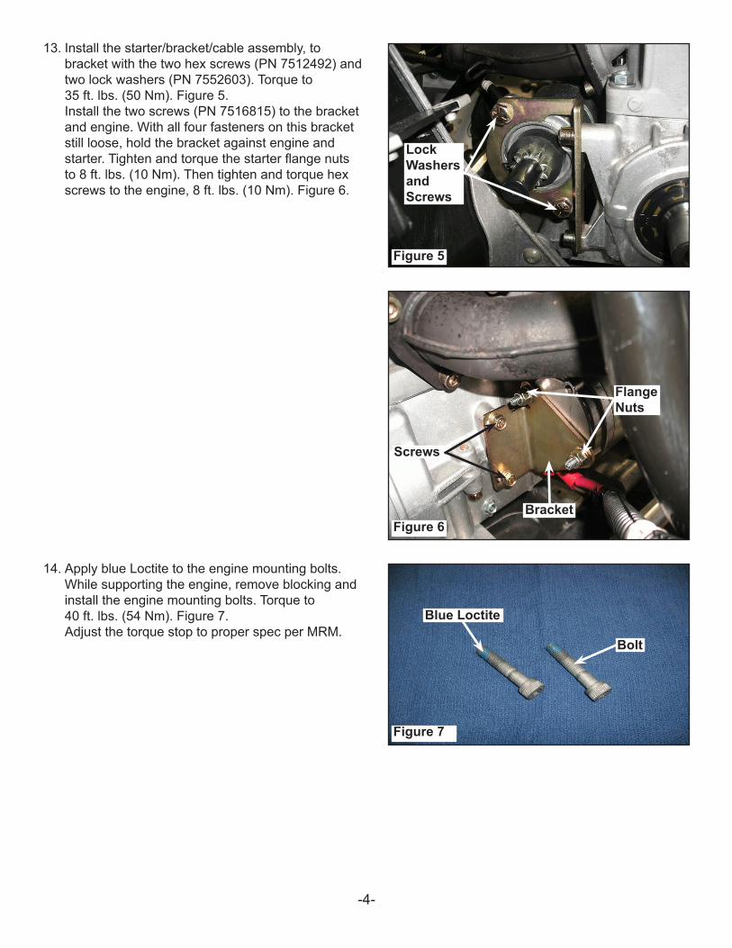
11. Loosen the engine torque stop and remove the left hand engine mount bolts. Lift left hand side of the engine up and rearward, then securely block the engine. Do not over apply lift force. Figure 3.
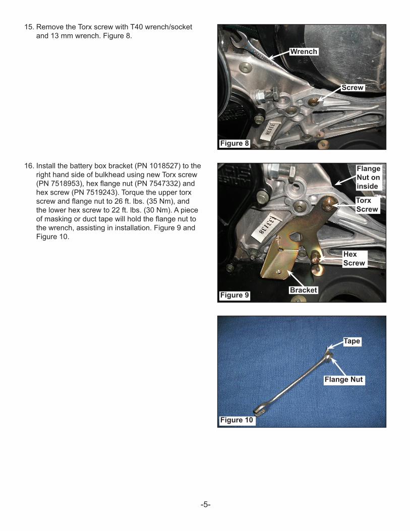
12. Install the front plated starter bracket (PN 5257396) to engine with the two hex socket screws (PN 7516730). Torque to 22 ft. lbs. (30 Nm). Figure 4.
Figure 2
Figure 3
Figure 4
Flange Nut
Bracket Washer, PN 7552801 Nut, PN 7542105
Bracket
Cable, Part number label
Screws
Engine Blocking
Torque Stop
Engine Mount Bolts
-4-
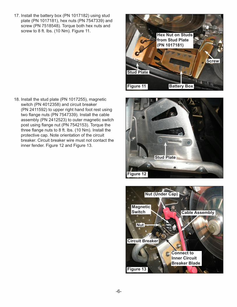
13. Install the starter/bracket/cable assembly, to bracket with the two hex screws (PN 7512492) and two lock washers (PN 7552603). Torque to 35 ft. lbs. (50 Nm). Figure 5. Install the two screws (PN 7516815) to the bracket and engine. With all four fasteners on this bracket still loose, hold the bracket against engine and starter. Tighten and torque the starter flange nuts to 8 ft. lbs. (10 Nm). Then tighten and torque hex screws to the engine, 8 ft. lbs. (10 Nm). Figure 6.
14. Apply blue Loctite to the engine mounting bolts. While supporting the engine, remove blocking and install the engine mounting bolts. Torque to 40 ft. lbs. (54 Nm). Figure 7. Adjust the torque stop to proper spec per MRM.
Figure 5
Figure 6
Figure 7
Lock Washers and Screws
Screws
Bracket
Bolt
Flange Nuts
Blue Loctite
-5-
BracketFlange Nuts
Flange Nut
Flange Nut
15. Remove the Torx screw with T40 wrench/socket and 13 mm wrench. Figure 8.
16. Install the battery box bracket (PN 1018527) to the right hand side of bulkhead using new Torx screw (PN 7518953), hex flange nut (PN 7547332) and hex screw (PN 7519243). Torque the upper torx screw and flange nut to 26 ft. lbs. (35 Nm), and the lower hex screw to 22 ft. lbs. (30 Nm). A piece of masking or duct tape will hold the flange nut to the wrench, assisting in installation. Figure 9 and Figure 10.
Figure 8
Figure 9
Figure 10
Tape
Screw
Torx Screw
Flange Nut on inside
Bracket
Wrench
Hex Screw
Flange Nut
-6-
17. Install the battery box (PN 1017182) using stud plate (PN 1017181), hex nuts (PN 7547339) and screw (PN 7518548). Torque both hex nuts and screw to 8 ft. lbs. (10 Nm). Figure 11.
18. Install the stud plate (PN 1017255), magnetic switch (PN 4012358) and circuit breaker (PN 2411592) to upper right hand foot rest using two flange nuts (PN 7547339). Install the cable assembly (PN 2412523) to outer magnetic switch post using flange nut (PN 7542153). Torque the three flange nuts to 8 ft. lbs. (10 Nm). Install the protective cap. Note orientation of the circuit breaker. Circuit breaker wire must not contact the inner fender. Figure 12 and Figure 13.
Battery Box
Stud Plate
Hex Nut on Studs from Stud Plate (PN 1017181)
Screw
Circuit Breaker
Cable AssemblyMagnetic Switch
Nut (Under Cap)
Nut
Figure 11
Figure 12
Figure 13
Stud Plate
Connect to Inner Circuit Breaker Blade
-7-
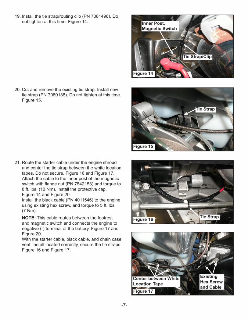
19. Install the tie strap/routing clip (PN 7081496). Do not tighten at this time. Figure 14.
20. Cut and remove the existing tie strap. Install new tie strap (PN 7080138). Do not tighten at this time. Figure 15.
21. Route the starter cable under the engine shroud and center the tie strap between the white location tapes. Do not secure. Figure 16 and Figure 17. Attach the cable to the inner post of the magnetic switch with flange nut (PN 7542153) and torque to 8 ft. lbs. (10 Nm). Install the protective cap. Figure 14 and Figure 20. Install the black cable (PN 4011546) to the engine using existing hex screw, and torque to 5 ft. lbs. (7 Nm).NOTE: This cable routes between the footrest and magnetic switch and connects the engine to negative (-) terminal of the battery. Figure 17 and Figure 20. With the starter cable, black cable, and chain case vent line all located correctly, secure the tie straps. Figure 16 and Figure 17.
Tie Strap/Clip
Inner Post, Magnetic Switch
Tie Strap
Tie Strap
Existing Hex Screw and Cable
Center between White Location TapeFigure 17
Figure 16
Figure 15
Figure 14
-8-
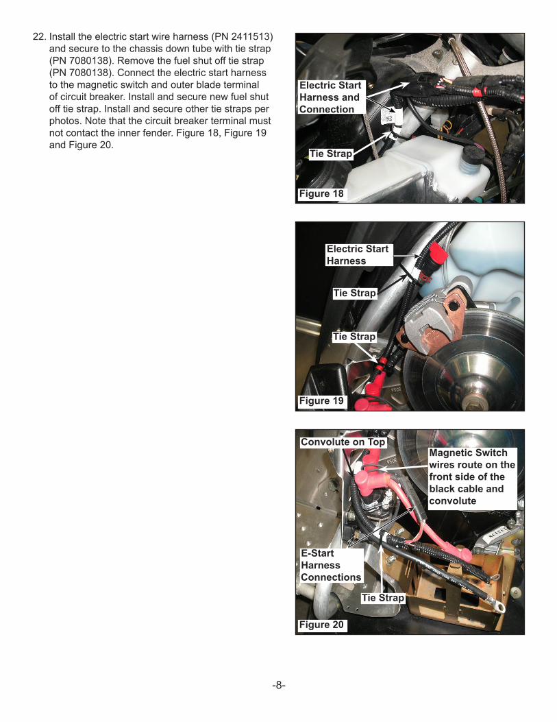
22. Install the electric start wire harness (PN 2411513) and secure to the chassis down tube with tie strap (PN 7080138). Remove the fuel shut off tie strap (PN 7080138). Connect the electric start harness to the magnetic switch and outer blade terminal of circuit breaker. Install and secure new fuel shut off tie strap. Install and secure other tie straps per photos. Note that the circuit breaker terminal must not contact the inner fender. Figure 18, Figure 19 and Figure 20.
Tie Strap
Tie Strap
Tie Strap
Tie Strap
Electric Start Harness and Connection
Electric Start Harness
E-Start Harness Connections
Convolute on Top
Figure 18
Figure 19
Figure 20
Magnetic Switch wires route on the front side of the black cable and convolute
-9-
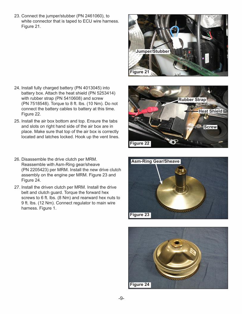
23. Connect the jumper/stubber (PN 2461060), to white connector that is taped to ECU wire harness. Figure 21.
24. Install fully charged battery (PN 4013045) into battery box. Attach the heat shield (PN 5253414) with rubber strap (PN 5410608) and screw (PN 7518548). Torque to 8 ft. lbs. (10 Nm). Do not connect the battery cables to battery at this time. Figure 22.
25. Install the air box bottom and top. Ensure the tabs and slots on right hand side of the air box are in place. Make sure that top of the air box is correctly located and latches locked. Hook up the vent lines.
26. Disassemble the drive clutch per MRM. Reassemble with Asm-Ring gear/sheave (PN 2205423) per MRM. Install the new drive clutch assembly on the engine per MRM. Figure 23 and Figure 24.
27. Install the driven clutch per MRM. Install the drive belt and clutch guard. Torque the forward hex screws to 6 ft. lbs. (8 Nm) and rearward hex nuts to 9 ft. lbs. (12 Nm). Connect regulator to main wire harness. Figure 1.
Jumper/Stubber
Rubber Strap
Heat Shield
Screw
Asm-Ring Gear/Sheave
Figure 21
Figure 22
Figure 23
Figure 24
-10-P/N 9925037 Rev 01 10/13
28. Confirm correct location of all cables and wiring. Install exhaust system and torque the exhaust resonator nut/bolt to 10 ft. lbs. (14 Nm). Install the hood and torque the screws to 7 ft. lbs. (10 Nm). Connect the hood and chassis harness.
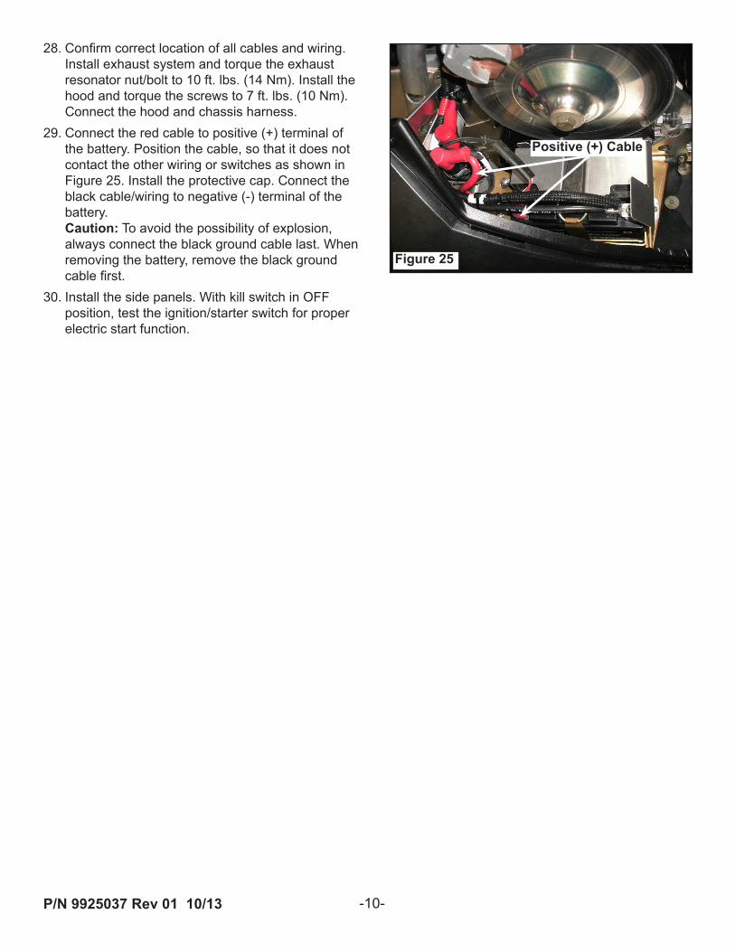
29. Connect the red cable to positive (+) terminal of the battery. Position the cable, so that it does not contact the other wiring or switches as shown in Figure 25. Install the protective cap. Connect the black cable/wiring to negative (-) terminal of the battery. Caution: To avoid the possibility of explosion, always connect the black ground cable last. When removing the battery, remove the black ground cable first.
30. Install the side panels. With kill switch in OFF position, test the ignition/starter switch for proper electric start function.
Positive (+) Cable
Figure 25