Embed Size (px)
Citation preview
1
Project: PAthways for Carbon Transitions
Project acronym: PACT
Project Number: 225503
Deliverable Dl3 Technology offer for production of goods and services
Qualitative description of the links between social services and technologies in a post-carbon society
and data for energy and CO2 intensity of materials
Final report 29 June, 2011
Authors: J.-P. Birat1 – M.Chiappini1 – C. Ryman2 – J. Riesbeck2
1ArcelorMittal Global R&D, Maizières, France 2MEFOS-SWEREA, Luleå, Sweden
Dissemination level: CO
2 29 June 2011
EXECUTIVE SUMMARY
PACT Deliverable Dl3 6 Technology offer for production of goods and services - Qualitative description of the
links between social services and technologies in a post-carbon society and data for en-ergy and CO2 intensity of materials
Authors: J.-P. Birat1 – M.Chiappini1 – C. Ryman2 – J. Riesbeck2 1ArcelorMittal Global R&D, Maizières, France
2MEFOS-SWEREA, Luleå, Sweden
This deliverable addresses the issue of structural materials (steel, aluminum, cement, plastics, wood and glass, in this study), which have several important properties with regards to the purposes of the PACT project:
• they are bulk materials,
• they are used and therefore produced en masse,
• they account for a large part of the energy and CO2 footprint of the industrial sector, which it-self is a significant part of all anthropogenic activities.
• structural materials are ubiquous, as they are used today either in almost every artifact or in the machines and industrial complexes that are used to make them.
The deliverable examines each material from the triple standpoint of:
• production volume,
• specific energy consumption
• and CO2 emissions.
A state-of-art for today (2010) is given and projections for 2050, based on scenarios available in the literature, are analyzed. Needless to say, the foresight information is not fully coherent, even taking on board the various scenarios examined by authors. This is the downside of many future studies.
One strong conclusion of this deliverable is that the bulk materials of 2010 will continue to be the ma-jor bulk materials in 2050. They will remain the same but will change and evolve, in their properties and behaviors. This will move in the direction of higher levels of properties. However, the core na-ture of these materials will remain the same.
This is actually a historical trend, as these same materials have been playing that role for historic peri-ods of time: steel, cement, non-ferrous metals like copper and zinc, wood, have been used for thou-sands of years; aluminum was invented at the same time as electricity came to be used in a modern way, more than a century ago, and plastics are of the same generation as organic chemistry based on the large scale use of oil, also roughly one century old.
Completely new materials will be invented in the next 40 years, but they are not likely to displace structural materials in significant volumes. This would not necessarily be true of functional materials, which are in some respects the contrary of structural materials.
The other conclusion of this work is that the new artefacts that will be developed for the post-carbon society will mostly use these same structural materials. New artefacts do not go with new materials, for many reasons, one being that innovations that succeed cannot pile up too many different levels of innovation in their design.
The volume of these bulk materials will increase dramatically by 2050, a two-fold increase on the av-erage. It will be driven by population growth and by the economic growth which will bring higher standards of living to more people in the world - as is happening today outside of Europe.

3 29 June 2011
This is due to the fact that they will continue to be central to all artefacts as they are already today.
These projections take on board a certain level of dematerialization, i.e. a leaner way of using materi-als and resources, based on eco-design, reuse and recycling, but the overall trend is in favor of more production, worldwide.
All structural materials have broad leeway for reducing energy consumption and GHG emissions, a kind of theoretical potential that will only be collected if political, economic and business issues are sorted out to make it happen.
Energy savings are possible, but most of the gains will come from more recycled content. Some mate-rials are already performing at high level today, with therefore only a limited potential for improve-ment, but many others can improve their performance.
Reduced GHG emissions are also possible, virtually to the level that will be needed for mitigating Climate Change, if the political and economic conditions for making the switch possible are created. This by itself is a formidable task, but one that is not the focus of PACT.
4 29 June 2011
Contents
1 Introduction ........................................................................................................................ 8 1 Introduction ........................................................................................................................ 8 2 Prolegomena..................................................................................................................... 10
2.1 Materials .................................................................................................................... 10 2.2 Historical trends and foresight projections................................................................ 11 2.3 Materials adaptation to Climate Change ................................................................... 19 2.4 Trends on structural materials for the PACT horizon ...............................................20
3 Qualitative description of materials use in society........................................................... 22 3.1 Images of the post-carbon society and key drivers.................................................... 22
3.1.1 Economic and social stability............................................................................. 22 3.1.2 Population and cities in 2050 ............................................................................. 23 3.1.3 Materials in 2050................................................................................................ 23 3.1.4 An economy putting a strong emphasis on recycling in 2050 ........................... 24 3.1.5 Energy in 2050 ................................................................................................... 24 3.1.6 Information technologies.................................................................................... 25
3.2 Mobility ..................................................................................................................... 25 3.2.1 Description and influencing drivers ................................................................... 26 3.2.2 Technologies ...................................................................................................... 26 3.2.3 Infrastructures for mobility ................................................................................ 27 3.2.4 Materials and technologies................................................................................. 27
3.3 Buildings and shelter ................................................................................................. 28 3.3.1 Description and influencing drivers ................................................................... 28 3.3.2 Means and technologies ..................................................................................... 29 3.3.3 Materials and technologies................................................................................. 30
3.4 Conclusions on solutions, technologies and materials ..............................................30 4 Data for energy and CO2 intensity of materials ............................................................... 31
4.1 Steel ........................................................................................................................... 32 4.1.1 Energy consumption - Steel ............................................................................... 32 4.1.2 CO2 consumption - Steel .................................................................................... 32 4.1.3 Foresight projections .......................................................................................... 38
4.2 Aluminum.................................................................................................................. 39 4.2.1 Introduction ........................................................................................................ 39 4.2.2 Techniques to produce Aluminum ..................................................................... 39 4.2.3 Energy demand 2010.......................................................................................... 40 4.2.4 Contributions to greenhouse gas emissions 2010 .............................................. 41 4.2.5 Scope I................................................................................................................ 41 4.2.6 Scope II .............................................................................................................. 41 4.2.7 Future scenarios.................................................................................................. 42 4.2.8 Energy demand 2050.......................................................................................... 42 4.2.9 GHG emissions 2050 ......................................................................................... 43 4.2.10 Scope I ............................................................................................................ 43 4.2.11 Scope II........................................................................................................... 44 4.2.12 Conclusions .................................................................................................... 44
4.3 Cement....................................................................................................................... 45 4.3.1 Energy consumption........................................................................................... 45 4.3.2 CO2 emissions - cement ..................................................................................... 45
5 29 June 2011
4.4 Wood ......................................................................................................................... 47 4.4.1 Wood has a complex carbon impact .................................................................. 47 4.4.2 Energy requirements and CO2 emissions for structural wood ........................... 48 4.4.3 Displacement factors of wood product substitution........................................... 49
4.5 Glass .......................................................................................................................... 50 4.5.1 Introduction ........................................................................................................ 50 4.5.2 GLASS production............................................................................................. 51 4.5.3 Energy demand and CO2 emissions in glass production.................................... 52 4.5.4 Energy requirement and CO2 emission .............................................................. 54 4.5.5 Production foresight ........................................................................................... 55
4.6 Plastics ....................................................................................................................... 56 4.7 Summary on the carbon and energy footprints of structural materials...................... 58
5 Methodological caveats - Life Cycle Thinking (LCT) & Social Value of Materials and of other commodities and services (SOVAMAT) ........................................................................ 63 6 Appendices regarding CO2 and energy intensity of structural materials ......................... 66
6.1 Steel ........................................................................................................................... 67 6.2 Cement....................................................................................................................... 68 6.3 Plastics ....................................................................................................................... 68
6.3.1 Definition ........................................................................................................... 68 6.3.2 Brief history of plastics ...................................................................................... 69 6.3.3 Importance of plastics ........................................................................................ 69 6.3.4 Overview of the plastic industry ........................................................................ 69 6.3.5 Energy demand for plastics production.............................................................. 72
7 References ........................................................................................................................ 77
6 29 June 2011
List of figures
Figure 1. final energy consumption per sector (EDF, 2009).................................................................................. 8 Figure 2 . evolution of the annual production of some structural material plus plastics over 100 years [] ......... 10 Figure 3 . evolution of steel production until 2050............................................................................................... 11 Figure 4 . evolution of cement production until 2050 (reference BAU and 450 scenarios). Production in kt/y.. 12 Figure 5 . World crude steel production projections (source: RITE)................................................................... 12 Figure 6 . CO2 generation by the world steel industry in 2050 (source: RITE)...................................................12 Figure 7. Forecast of steel demand by 2050: (left) by region; (right) by end use (source: University of Tokyo). 13 Figure 8. evolution of glass production until 2050 (reference BAU and 450 scenarios). Production in kt/y....... 13 Figure 9. evolution of aluminum production until 2050 (reference BAU and 450 scenarios). ........................... 14 Figure 10. Production of steel and cement 2006 and 2050 according to IEA projections................................... 14 Figure 11. Production of aluminum, glass and plastics 2050 according to IEA predictions................................ 14 Figure 12. CO2 generation by the world steel industry until 2050 (source: LEPII)............................................ 16 Figure 13 . reduction of CO2 generation by the world steel industry until 2050 (source: RITE)......................... 16 Figure 14 . world global CO2 generation until 2050 (source: LEPII)................................................................. 17 Figure 15 . Direct reduction by technology options as reported by the IEA (low and high blue scenarios) ........ 18 Figure 16 . simplified projections of CO2 emission sin the Steel sector............................................................... 18 Figure 17 . Three different viewpoints to compare materials in the construction sector...................................... 19 Figure 18 . Spatial organization of cities (city pattern)........................................................................................ 23 Figure 19. Trans-European transport Network (TEN.T) — Priority axes and projects by 2020.......................... 26 Figure 20 . Concepts of small vehicles and of renewable energy supply in a parking ramp................................ 27 Figure 21 .Footbridge in Paris (credit CSTB) and bus stop with interactive service (MIT project).................... 27 Figure 22 . Trend of energy consumption in kWh/m2 in housing in France from 1984 to 2006........................... 28 Figure 23 . A view of the BedZED eco-area......................................................................................................... 29 Figure 24 .Some principles of an eco-house......................................................................................................... 29 Figure 25 . energy data (today)............................................................................................................................ 32 Figure 26 . definition of the boundaries of the systems defined around a plant by theGHG Protocol................ 34 Figure 27. LCI of an integrated steel mill, without any "allocation".................................................................... 36 Figure 28. LCI of the same integrated steel mill, with "allocations".................................................................... 36 Figure 29 . amounts of allocations taken on board in the LCI for various co/by.products.................................. 36 Figure 30 . schematics of the plants included in the model steel mill (oxygen, nitrogen and argon plant, lime kiln, power plant to combust process gases, coke ovens and sinter plant)................................................................... 37 Figure 31. Aluminum industry production flow (IAI 2010)................................................................................... 39 Figure 32 . scheme of cement production and pie chart of CO2 emissions categories......................................... 46 Figure 33: Elements of the forest products industry related to its greenhouse gas profile (1)............................. 48 Figure 34. Glass production by subsector in the EU25, 2007 (Schmitz et al, Energy Policy, 2011).................... 50 Figure 35 . energy consumption for producing one ton of structural materials in 2010 and projected in 2050.. 61 Figure 36. specific CO2 (equivalent) emissions related to structural materials for producing and disposing (end of life) of them. Energy.related emissions (scope II) are also included............................................................... 61 Figure 37 . comparison between specific energy consumption in 2010 and 2050 of major structural materials. 62 Figure 38. comparison between specific energy consumption in 2010 and 2050 of major structural materials.. 62 Figure 39. Example of monomers used for polymer production (resp. polyethylene and polypropylene)............ 68 Figure 40. The Ethylene chain (source IEA)......................................................................................................... 69 Figure 41. World production 1950-2009.............................................................................................................. 70 Figure 42. Geographical share............................................................................................................................. 70 Figure 43. Estimated plastics flows to final products in the global economy,...................................................... 70 Figure 44. Visualisation of the weighting of polymers by main end.use sectors, Europe 2009............................ 71 Figure 45. European plastics demand grouped by resin types, 2009 situation..................................................... 71
7 29 June 2011
List of tables
Table 1 . comparison between the various projections for steel production in 2050............................................ 15 Table 2. technologies and associated materials for mobility services.................................................................. 28 Table 3. technologies and associated materials for housing services................................................................... 30 Table 4 . CO2 emissions by plant in a steel mill................................................................................................... 33 Table 5 . examples of specific CO2 emissions (emission factors) for steel production......................................... 34 Table 6 . estimation of the uncertainty on scope I + II emissions due to the dispersion of level of CO2 efficiency across the world.................................................................................................................................................... 37 Table 7. Energy consumption 2010 in primary and secondary Aluminum production......................................... 40 Table 8. Aluminum production 2010 in primary and secondary Aluminum......................................................... 40 Table 9. Scope I emissions 2010 in primary and secondary Aluminum production............................................. 41 Table 10. Scope II emissions 2010 in primary aluminum production................................................................... 42 Table 11. Energy consumption 2050 in production of primary and secondary Aluminum................................... 43 Table 12. Aluminum production 2050 in primary and secondary aluminum with different recycling rate scenarios............................................................................................................................................................... 43 Table 13. Scope I emissions 2050 in primary and secondary Aluminum production........................................... 44 Table 14. Scope II emissions 2050 in primary and secondary Aluminum production.......................................... 44 Table 15. Typical energy intensities for the production of wood products, and predictions for 2050.................. 48 Table 16. Typical CO2 intensities for the production of wood products, and predictions for 2050..................... 49 Table 17. Theoretical energy requirements to melt different glass types (IPPC 2010)........................................ 52 Table 18. Examples of reported specific energy consumption per process in the glass sector............................. 53 Table 19. Estimated specific energy consumption of glass melting furnace in the U.S........................................ 53 Table 20. Energy intensities for the production of glass today, and predictions for 2050.................................... 55 Table 21. Estimated CO2 emission intensities of Soda.Lime glass today, and predictions for 2050.................... 55 Table 22. Estimated CO2 emission intensities of Boro.Silicate glass today, and predictions for 2050................ 55 Table 23. Plastics data on energy needs and CO2 emissions............................................................................... 56 Table 24. Scope I and scope II CO2 emissions..................................................................................................... 56 Table 25. energy consumption of important material sectors (GJ/t)..................................................................... 58 Table 26. CO2 emissions of important material sectors (Al: aluminum).............................................................. 59 Table 27. End.sectors share for plastics demand in Europe, 2009....................................................................... 71 Table 28. Energy consumption and GWP broken down per process activities, per cradle to gate view, and per feedstock content................................................................................................................................................... 73 Table 29. Energy demand and emissions per ton of plastic mix........................................................................... 74 Table 30. Compared end of life for plastics, Europe and World situations.......................................................... 74 Table 31. Data on best, average, and worst technologies (IPPC, IEA)................................................................ 75 Table 32. Improvement potentials of energy demand mitigation .......................................................................... 76 Table 33. Improvement potentials of CO2 mitigation for some European countries........................................... 76 Table 34. Best performing indicators for energy demand and GWP per ton of plastic mix................................. 76 Table 35 . Energy demand per scope.................................................................................................................... 76
8 29 June 2011
1 Introduction This work package is here to provide a vision of structural materials both longitudinally, along the stream of time from today until the second half of this century (diachronic description) and, transver-sally, across the economy and the supply chain of goods and services where they play a key role (syn-chronic description).
By structural materials, we mean the materials that constitute the structure of artefacts used to make things (industrial production), of final consumer goods and of means and tools used to provide ser-vices, including the enclosures, packaging and housing of these objects: the core of machines, the structure of automobiles or trains, the infrastructure of housing, buildings and also of civil engineering equipment, from roads to rail tracks and from dams to airports. More specifically we include cement, steel, non-ferrous metals, wood and paper/cardboard, glass and plastics.
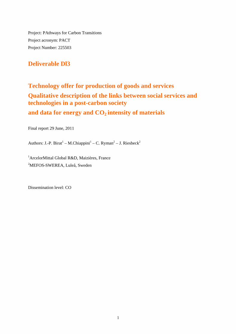
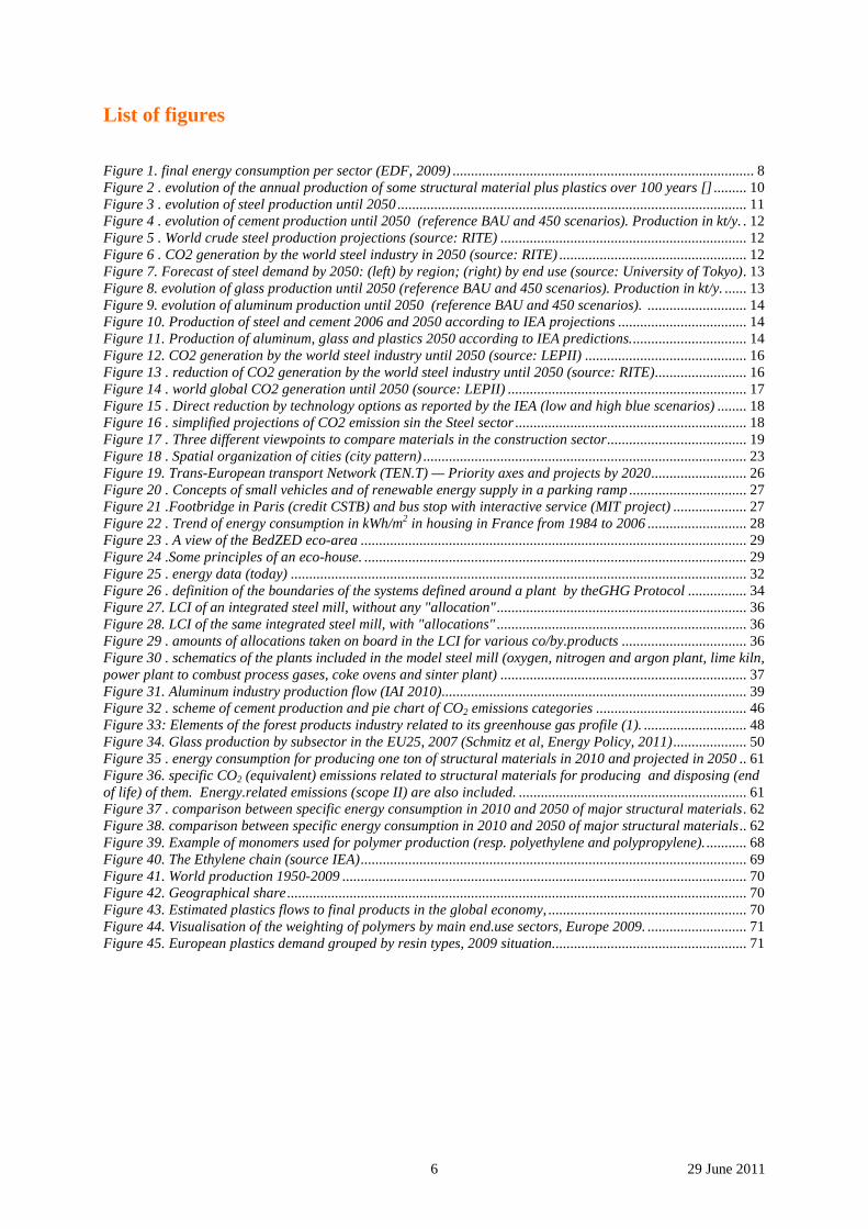
These materials account for most of the materials produced and used in the world in terms of volume, energy needs and environmental footprint, including GHG emissions. Sector turnover and amount of direct and indirect jobs are also very large1. As an example, the sectoral final energy consumption for 5 major EU countries is given in Figure 1 and shows the importance of some of the key materials that we have been mentioning as structural materials.
Figure 1- final energy consumption per sector (EDF, 2009)
Note that these structural materials have been robust across historical time, meaning by this that they have been used for at least a century for the youngest and for many centuries, even millennia, for the oldest ones. This is due to the fact that they are actually cumulative materials2. These materials have evolved by continuous progress for very times, which have been cumulated over the same historical periods of time. They have thus become lean in terms of energy and raw materials used to produce
1 In Europe (EU) the Steel sector alone accounts for 422,000 direct jobs, 23 million jobs in the steel value (sup-ply) chain and 190 million jobs in the local communities (teachers, bankers, doctors, etc.). In terms of GDP, again in the EU and Europe, 187 G€ total turnover of the steel sector (1.5 % of 12,260 G€ PPP, regional GNP), while 8,440 G€ of the EU GDP is related to steel. 2 Cumulative here refers to cumulative technologies, which are the result of cumulative innovation, i.e. a con-tinuous effort to develop the technology by a series of step-by-step or breakthrough developments all addressing the same object. The EU Commission liked this concept a few years back, to emphasize the important of eco-nomic activities which are robust and durable.
9 29 June 2011
them and they are delivering high-level usage properties and hence a high property/price ratio [1]. They also are at the heart of the technological episteme of today, which is also quite robust over time. Moreover, the amount of capital frozen in industrial equipment related to these materials is huge, which is another reason for their robustness, for the longevity of their sector and for the viscosity of moving to alternative solutions.
Structural materials bear other names, some of which are negatively connoted, like bulk, conven-tional or traditional materials. The implicit connotation is that they are "old fashioned". We resist using these expressions, because they are simply not true. Love or life are not particularly old-fashioned, they are just enduring and transcending time, historical time. The same is true of steel, or wood or of any of the structural materials.
The deliverable is organized in four sections:
• the first one is devoted to a presentation of structural materials in terms of volume, energy and GHG emissions from today until 2050;
• the second section deals with the use of materials in society to meet economic and social de-mand;
• the third section gives more focused information on materials energy and CO2 footprints,
• while the fifth section gives an overview, material by materials of its main relevant features useful to flesh out the PACT analysis.
One difficulty has been encountered all through this chapter relative to the meaning of the 2050 time horizon. If it means 2050 as opposed to 2040 and 2060, then the chapters' authors do not really be-lieve that it is a proper time stamp for the post-carbon society: most of the changes that are intuitively related to such a post-carbon society will not have taken place yet by then; but if it is only a symbolic date for referring to this post-carbon society, then of course it is all right. Some of the quantitative in-formation given in this chapter is rather precisely related to 2050, while the qualitative story telling is more fuzzily timed.
10 29 June 2011
2 Prolegomena
2.1 Materials
The essential role that materials play in society has been recognized by a broad array of disciplines: soft and hard sciences interface on the issue [2], from anthropology, history or economics to materials science, complemented by application technologies such as political science, Life Cycle Analysis (LCA) or Material Flow Analysis (MFA). The core of the analysis is that, from the emergence of mankind as a society in the Lower Paleolithic to the timeline of human History, materials have been associated with this millennia-long evolution: civilization has been the appropriation of the world by man both at a physical and a symbolic level and materials have been fundamentally instrumental in making this possible.
Paradoxically though, there are very few studies, which project this understanding into the future, in a long-term vision supported by full-fledged prospective or future studies [3,4]. This may be due to the fact that materials, at a symbolic level, are the vehicles of the dreams of mankind for a continuous progress that would lead to a better life. Thus, studies on new materials abound, which promise ex-traordinary new properties, but they come in waves3, the new wave chasing the former one, or putting it back into a more confined perspective. However a comprehensive vision of what may be to come is lacking, probably because future studies are not conducted as part of a comprehensive agenda to map possible futures but as an answer to questions that are raised at a particular time. There are more popular issues than that of materials and therefore they do not get in the headlines often enough to warrant his kind of attention.
Materials are viewed in very different ways by the disciplines that talk about them [5].
The distinction between structural and functional materials [6] is common among material scientists and economists to separate bulk materials from materials exhibiting very specific functions. The for-mer constitute the structural core of most human artefacts - from infrastructure, investments goods and consumer goods, while the latter provide very focused and sophisticated properties to goods and prod-ucts: for example, carbon steel is a structural material while electrical steel (Silicon steels) is a func-tional one.
In a language favored by economists, the former are also called intermediary goods or commodities, while the latter are specialties.
000
500
1 000
1 500
2 000
2 500
3 000
1 900 1 920 1 940 1 960 1 980 2 000
Wor
ld Pro
duc
tion
(million
ton
s/year) Cement Steel Wood Plastics
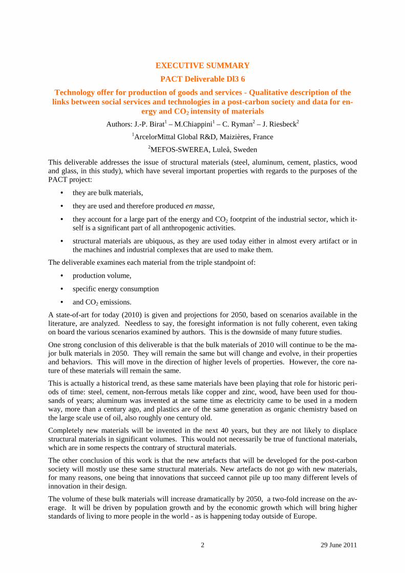
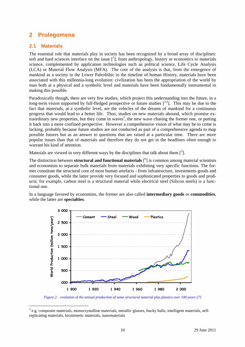
Figure 2 – evolution of the annual production of some structural material plus plastics over 100 years [7]
3 e.g. composite materials, monocrystalline materials, metallic glasses, bucky balls, intelligent materials, self-replicating materials, biomimetic materials, nanomaterials
11 29 June 2011
A lot of attention is continuously given to functional materials, as their diversity is literally limitless: many new materials are continuously being invented and they thus make good “material” for "break-ing news". On the other hand, functional materials only get in the news when some iconic object is erected, like the Millau bridge [8] or the Burj Khalifa highrise [9] in Dubai, but the materials them-selves stay in the background of the story, metaphorically and physically under the surface of things.
The work carried out in PACT is focused on structural materials, based on the rationale that they are produced in much higher volumes than functional ones, therefore requiring high absolute amounts of energy for their production and, in parallel, generating large quantities of greenhouse gases. Steel, for example, accounts for 5 to 6 % of anthropogenic CO2 emissions [10].
2.2 Historical trends and foresight projections
Information is available from the literature regarding demand and production of structural materials.
The past level of production of some important materials like steel, cement and wood, is shown in Figure 2 [7]. It also shows plastics or polymers.
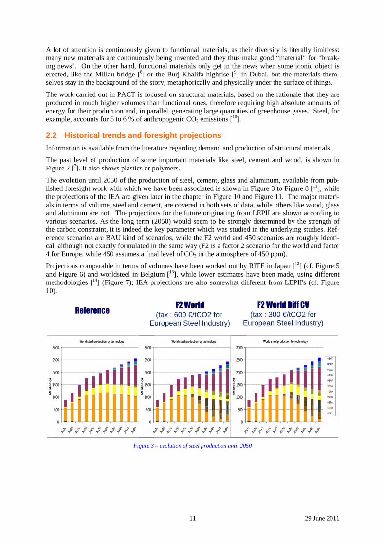
The evolution until 2050 of the production of steel, cement, glass and aluminum, available from pub-lished foresight work with which we have been associated is shown in Figure 3 to Figure 8 [11], while the projections of the IEA are given later in the chapter in Figure 10 and Figure 11. The major materi-als in terms of volume, steel and cement, are covered in both sets of data, while others like wood, glass and aluminum are not. The projections for the future originating from LEPII are shown according to various scenarios. As the long term (2050) would seem to be strongly determined by the strength of the carbon constraint, it is indeed the key parameter which was studied in the underlying studies. Ref-erence scenarios are BAU kind of scenarios, while the F2 world and 450 scenarios are roughly identi-cal, although not exactly formulated in the same way (F2 is a factor 2 scenario for the world and factor 4 for Europe, while 450 assumes a final level of CO2 in the atmosphere of 450 ppm).
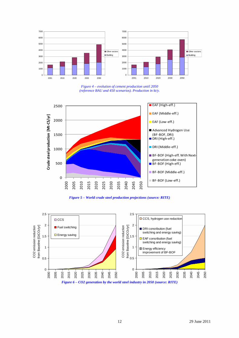
Projections comparable in terms of volumes have been worked out by RITE in Japan [12] (cf. Figure 5 and Figure 6) and worldsteel in Belgium [13], while lower estimates have been made, using different methodologies [14] (Figure 7); IEA projections are also somewhat different from LEPII's (cf. Figure 10).
ReferenceF2 World
(tax : 600 €/tCO2 for European Steel Industry)
F2 World Diff CV
(tax : 300 €/tCO2 for European Steel Industry)
0
500
1000
1500
2000
2500
3000
Mt s
tee
l/yr
World steel production by technology
EHT
SRP
ELA
ELB
EAF
DRA
DRP
BFB
BFA
BFR
OPH
0
500
1000
1500
2000
2500
3000
Mt s
tee
l/yr
World steel production by technology
EHT
SRP
ELA
ELB
EAF
DRA
DRP
BFB
BFA
BFR
OPH
0
500
1000
1500
2000
2500
3000
Mt s
tee
l/yr
World steel production by technology
EHT
SRP
ELA
ELB
EAF
DRA
DRP
BFB
BFA
BFR
OPH
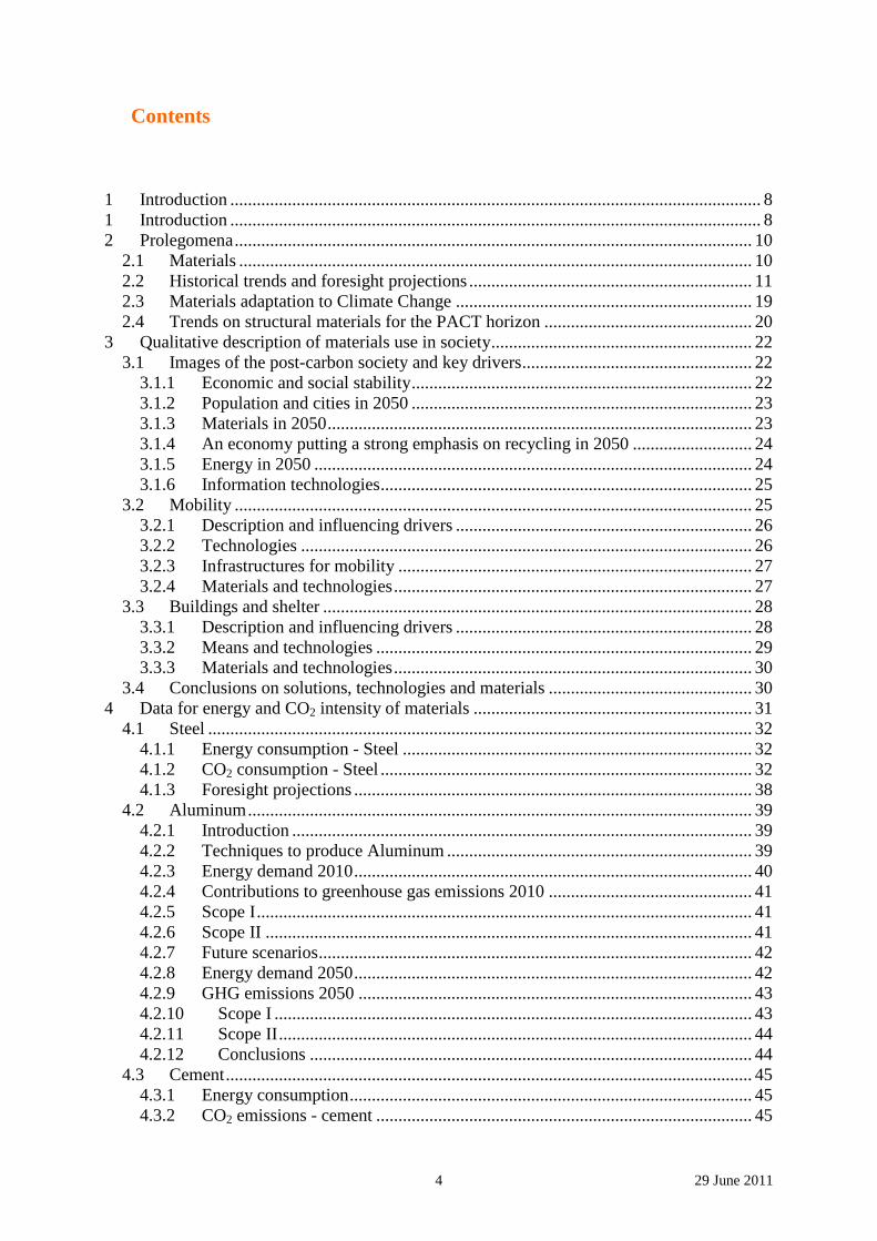
Figure 3 – evolution of steel production until 2050
12 29 June 2011
0
1000
2000
3000
4000
5000
6000
7000
2001 2010 2020 2030 2050
Other sectors
Building
0
1000
2000
3000
4000
5000
6000
7000
2001 2010 2020 2030 2050
Other sectors
Building
Figure 4 – evolution of cement production until 2050
(reference BAU and 450 scenarios). Production in kt/y.
Figure 5 – World crude steel production projections (source: RITE)
Figure 6 – CO2 generation by the world steel industry in 2050 (source: RITE)
0
0.5
1
1.5
2
2.5
2000
2005
2010
2015
2020
2025
2030
2035
2040
2045
2050
CO
2 em
issi
on r
educ
tion
from
Bas
elin
e [G
tCO
2/y
r]
CCS, hydrogen use reduction
DRI consribution (fuelswitching and energy saving)
EAF consribution (fuelswitching and energy saving)
Energy efficiencyimprovement of BF-BOF
0
0.5
1
1.5
2
2.5
2000
2005
2010
2015
2020
2025
2030
2035
2040
2045
2050
CO
2 em
issi
on r
educ
tion
from
Bas
elin
e [G
tCO
2/y
r]
CCS
Fuel switching
Energy saving
0
500
1000
1500
2000
2500
20
00
20
05
20
10
20
15
20
20
20
25
20
30
20
35
20
40
20
45
20
50
Cru
de
ste
el p
rod
uct
ion
[M
t-C
S/yr
]
EAF (High-eff.)
EAF (Middle-eff.)
EAF (Low-eff.)
Advanced Hydrogen Use
(BF-BOF, DRI)DRI (High-eff.)
DRI (Middle-eff.)
BF-BOF (High-eff. With Next-
generation coke oven)BF-BOF (High-eff.)
BF-BOF (Middle-eff.)
BF-BOF (Low-eff.)
13 29 June 2011
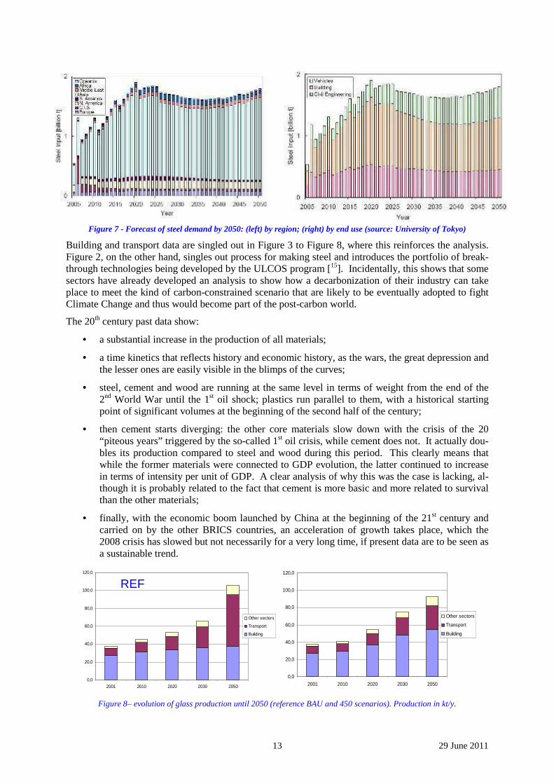
Figure 7 - Forecast of steel demand by 2050: (left) by region; (right) by end use (source: University of Tokyo)
Building and transport data are singled out in Figure 3 to Figure 8, where this reinforces the analysis. Figure 2, on the other hand, singles out process for making steel and introduces the portfolio of break-through technologies being developed by the ULCOS program [15]. Incidentally, this shows that some sectors have already developed an analysis to show how a decarbonization of their industry can take place to meet the kind of carbon-constrained scenario that are likely to be eventually adopted to fight Climate Change and thus would become part of the post-carbon world.
The 20th century past data show:
• a substantial increase in the production of all materials;
• a time kinetics that reflects history and economic history, as the wars, the great depression and the lesser ones are easily visible in the blimps of the curves;
• steel, cement and wood are running at the same level in terms of weight from the end of the 2nd World War until the 1st oil shock; plastics run parallel to them, with a historical starting point of significant volumes at the beginning of the second half of the century;
• then cement starts diverging: the other core materials slow down with the crisis of the 20 “piteous years” triggered by the so-called 1st oil crisis, while cement does not. It actually dou-bles its production compared to steel and wood during this period. This clearly means that while the former materials were connected to GDP evolution, the latter continued to increase in terms of intensity per unit of GDP. A clear analysis of why this was the case is lacking, al-though it is probably related to the fact that cement is more basic and more related to survival than the other materials;
• finally, with the economic boom launched by China at the beginning of the 21st century and carried on by the other BRICS countries, an acceleration of growth takes place, which the 2008 crisis has slowed but not necessarily for a very long time, if present data are to be seen as a sustainable trend.
0,0
20,0
40,0
60,0
80,0
100,0
120,0
2001 2010 2020 2030 2050
Other sectors
Transport
Building
REF
0,0
20,0
40,0
60,0
80,0
100,0
120,0
2001 2010 2020 2030 2050
Other sectors
Transport
Building
Figure 8– evolution of glass production until 2050 (reference BAU and 450 scenarios). Production in kt/y.
14 29 June 2011
0,0
20,0
40,0
60,0
80,0
100,0
120,0
140,0
2001 2010 2020 2030 2050
Other sectors
Electricity transformation
Transport
Building
0,0
20,0
40,0
60,0
80,0
100,0
120,0
140,0
2001 2010 2020 2030 2050
Other sectors
Electricity transformation
Transport
Building
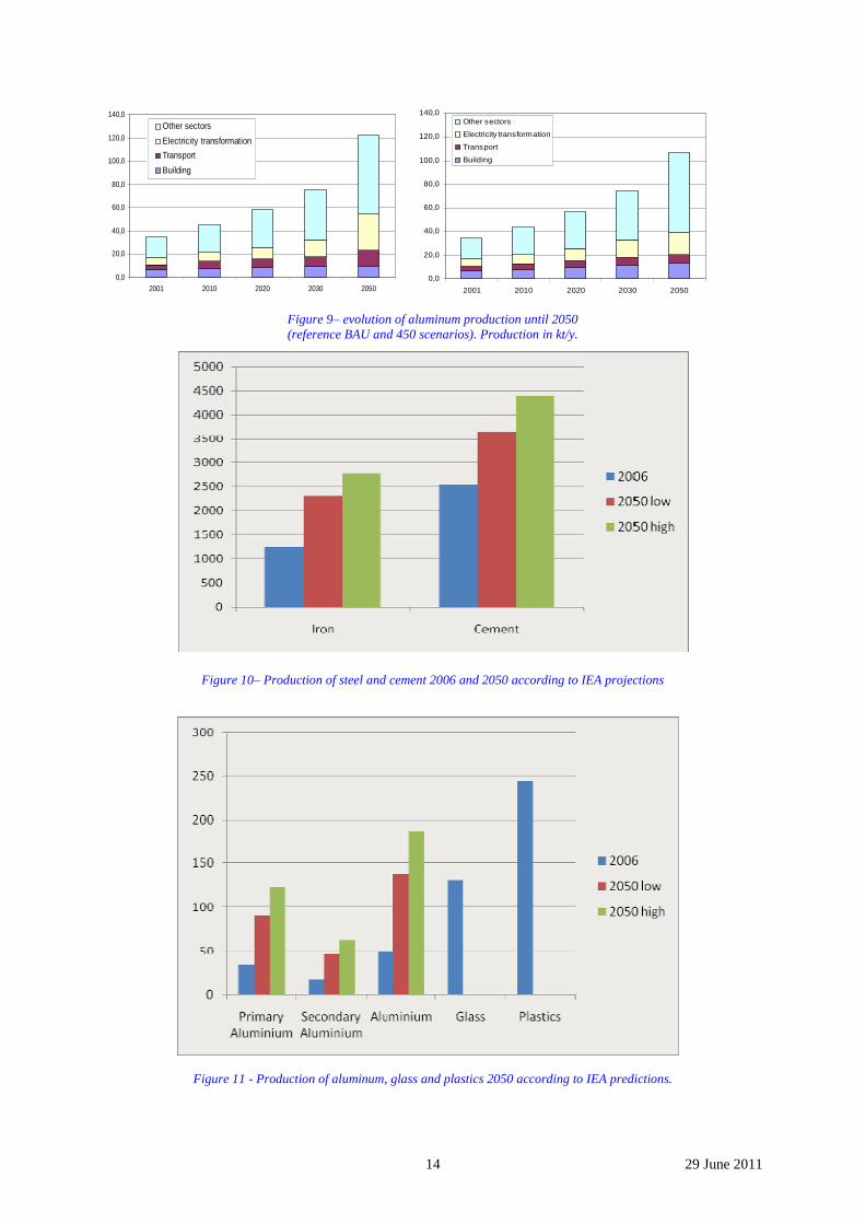
Figure 9– evolution of aluminum production until 2050 (reference BAU and 450 scenarios). Production in kt/y.
Figure 10– Production of steel and cement 2006 and 2050 according to IEA projections
Figure 11 - Production of aluminum, glass and plastics 2050 according to IEA predictions.
15 29 June 2011
The foresight data also exhibit some interesting features:
• the 2050 production of all materials shows a significant increase with respect to 2000, roughly a tripling in volumes (a 2.2% average growth rate along the period); this projects a strong in-crease in material intensity per capita, as the world population is to increase by roughly 30% “only” during the period. The intensity per unit of GDP exhibits an elasticity of roughly one with the increase in GDP.
• production level forecasts for 2050 are rather insensitive to the carbon constraint, like in the case of steel where slightly lower and slightly higher values are projected by 2 widely differ-ing variants of 2050 scenarios: aluminum and glass projections are slightly lower (signifi-cantly?) and cement is slightly higher. Nothing like the uncoupling of cement from the other materials, shown in the historical data record, is exhibited here, which probably goes to say that the underlying behavior of the markets has not been modeled into the studies as the effect had probably not been identified by the researchers and is certainly not well understood.
Is it possible to go beyond these general and careful statements, for example by saying that the produc-tion of steel will double in 2050 compared to its present level of production? The various projections are compared in Table 1: they differ by almost 1 billion tons of steel and this figure is less than what would show if unpublished data had been taken on board. Clearly, foresight studies are not predic-tions and it is difficult and hazardous to take them out of the context for which they have been pro-duced - what we have been doing to a limited extent here, though.
All these projections are based on rather different models originating from different schools of thought. POLES and Markal models, for example, are based on fairly different views of the way the economy works: refer to the original documents for an in-depth discussion of this point. One can't simply say that one is more or less true than the other, although one's school of thought would favor one over the other, POLES over Markal models for example in the case of the preferences of one of this report's author. What is interesting is that in spite of their diversity they do project trends, which are coherent, if they are taken as trends, not as exact quantitative projections.
Table 1 – comparison between the various projections for steel production in 2050
Source of estimates Annual production (Mt/yr) comments
ULCOS-LEPII 2,450 / 2,550 POLES estimates
RITE 2200 Markal model
Tokyo University 1800 MFA model
IEA Blue Maps (low/high) 2350 / 2700
Thus a statement like: "in 2050, assuming that the economy continues on its present tack without a major paradigm shift such as negative growth, steel production will increase to a large extend com-pared to today, more or less doubling from the present level" can be made, with all the fuzziness of the words that have been carefully selected. That similar statement can be made for cement or aluminum or glass reinforces the statement for steel and puts it in the family of positive visions of the future.
How do these projections of production translate in terms of GHG projections?
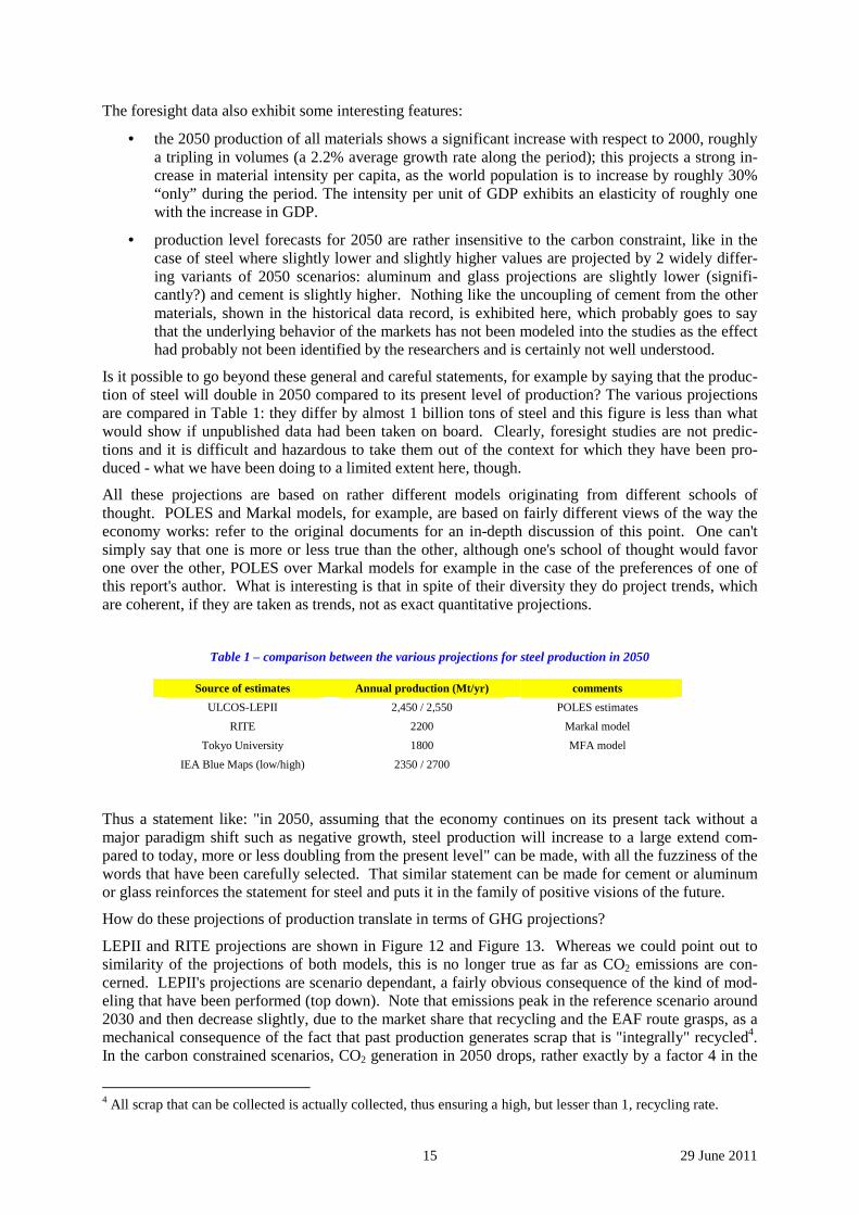
LEPII and RITE projections are shown in Figure 12 and Figure 13. Whereas we could point out to similarity of the projections of both models, this is no longer true as far as CO2 emissions are con-cerned. LEPII's projections are scenario dependant, a fairly obvious consequence of the kind of mod-eling that have been performed (top down). Note that emissions peak in the reference scenario around 2030 and then decrease slightly, due to the market share that recycling and the EAF route grasps, as a mechanical consequence of the fact that past production generates scrap that is "integrally" recycled4. In the carbon constrained scenarios, CO2 generation in 2050 drops, rather exactly by a factor 4 in the
4 All scrap that can be collected is actually collected, thus ensuring a high, but lesser than 1, recycling rate.
16 29 June 2011
"F2 world" and by a factor 3 in the "F2 differentiated carbon value world". The differences may or may not be significant: the very least that can be concluded is that the Differentiated Carbon Value (DCV) concept achieves a similar level of cuts as the usual uniform Carbon Value scheme. The re-sults are due to the behavior of the overall economy, not just of the Steel sector, as shown in Figure 14: the two models at this global scale are also close in their prediction, but they also do not achieve exactly the same level of cuts, because the set of values selected for the DCV model have not been fine tuned in order to show this exact balanced outcome.
Reference F2 World F2 World Diff CV
0
200
400
600
800
1000
1200
1400
1600
1800
2000
MtC
O2
/yr
World Steel CO2 emissions
Other zones
India
China
CIS
North America
Western Europe
0
200
400
600
800
1000
1200
1400
1600
1800
2000M
tCO
2/y
r
World Steel CO2 emissions
Other zones
India
China
CIS
North America
Western Europe
0
200
400
600
800
1000
1200
1400
1600
1800
2000
MtC
O2
/yr
World Steel CO2 emissions
Other zones
India
China
CIS
North America
Western Europe
Figure 12 - CO2 generation by the world steel industry until 2050 (source: LEPII)
Figure 13 – reduction of CO2 generation by the world steel industry until 2050 (source: RITE)
RITE projections only show a carbon constrained world. The reduction posted are then of a similar or-der of magnitude as those of LEPII. The way the cuts are achieved, however, is not explained in detail in the publications and the author of the present section is puzzled by the fact that energy savings would bring a larger proportion of the reduction, followed by fuel switching and CCS, which is differ-ent form his own understanding of the sector.
These results show what a top down modeling can produce: the level of cuts achieved is at the level of the pressure that is applied on the economy. In other words, since the value of carbon, in the POLES model for example, is calculated to produce a F2 world, this is indeed what happens: the model shows that it is possible, that there is a solution in the economic space, by implementing the kind of break-through technologies that the models posit in their technology database.
Whether this can be done in a practical and realistic way is an altogether different matter…!
0
0.5
1
1.5
2
2.5
2000
2005
2010
2015
2020
2025
2030
2035
2040
2045
2050
CO
2 em
issi
on r
educ
tion
from
Bas
elin
e [G
tCO
2/y
r]
CCS, hydrogen use reduction
DRI consribution (fuelswitching and energy saving)
EAF consribution (fuelswitching and energy saving)
Energy efficiencyimprovement of BF-BOF
0
0.5
1
1.5
2
2.5
2000
2005
2010
2015
2020
2025
2030
2035
2040
2045
2050
CO
2 em
issi
on r
educ
tion
from
Bas
elin
e [G
tCO
2/y
r]
CCS
Fuel switching
Energy saving
17 29 June 2011
Reference F2 World F2 World Diff CV
0
5
10
15
20
25
30
35
40
45
50
55
GtC
O2
/yr
World Total CO2 emissions
Electric sector
Transport
Residential & Service
Industry
0
5
10
15
20
25
30
35
40
45
50
55
GtC
O2
/yr
World Total CO2 emissions
Electric sector
Transport
Residential & Service
Industry
0
5
10
15
20
25
30
35
40
45
50
55
GtC
O2
/yr
World Total CO2 emissions
Electric sector
Transport
Residential & Service
Industry
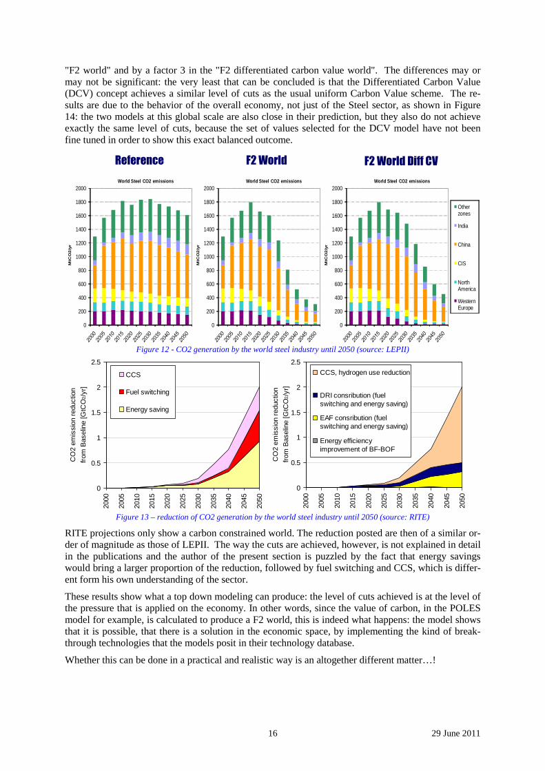
Figure 14 – world global CO2 generation until 2050 (source: LEPII)
There are similar projections for the other materials, but it is irrelevant to this review to present them. The discussion indeed becomes technology focused and thus clearly out of scope.
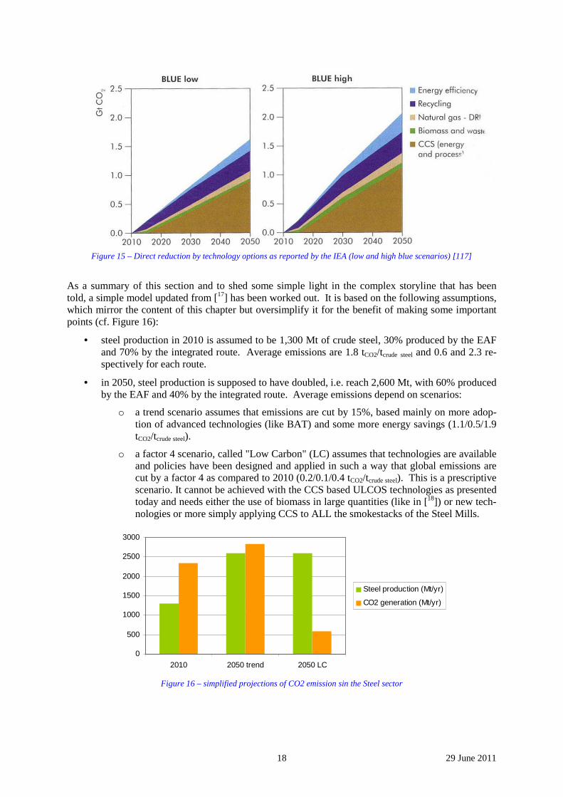
IEA projections are shown in Figure 15. The wedge diagram that is shown can be compared directly to RITE's. Again, the overall level of cuts is roughly similar, but the levers for achieving the reduction are different: CCS, biomass use, switch to natural gas (DRI), recycling and energy efficiency, listing them in a decreasing order of influence. This is more or less the reverse order of RITE's. Moreover, if one goes deeper into the analysis that is carried out by the IEA, one sees that both the use of natural gas and of scrap is allowed to increase fairly arbitrarily without the kind of restraints that are embed-ded in the economy: the amount of recycling is completely bound by past production and the amount of natural gas that can be used for producing steel is bound by costs and thus gas prices; these short-comings are acknowledged in the IEA report.
Note that these constraints have been built into the POLES model, because the model has the kind of high level description of the economy that makes it possible to take on board this level of complexity and because it has been developed by collaboration between economists and steel experts. This kind of "detail" is not completely explicit in the publications and there is a danger of accepting them all at the same level, even though they deal with similar problems with quite different tools. This flattening of scientific results is akin to philosophical relativism and is due to the fact that very many stake-holders express opinions and make decisions based on a shallow reading of existing results.
The technology options quoted in [16] by IEA meet the expectations of this author, but this is due to the fact that the data come from worldsteel and thus from ULCOS and other advanced CO2 mitigation steel technology programs. This however is rather unrelated with IEA's modeling: it is presented as "options" that the user can shop from. It is also meant, explicitly or not, to show that there are many solutions around and that technology will always have the last word in solving this kind of problems. Again, this is a technology-optimistic view, which is probably true at a vague and global scale, but does not necessarily apply to a narrow and focused problem.
Note also that in previous editions of the IEA report [16], the options were quite different and rather ill informed: in addition to the statements on using more scrap and more direct reduction, which we have already criticized, they singled out technologies which have not been particularly successful in terms of industrial implementation – probably based on available information, published by technology pro-viders with marketing and lobbying targets in mind. The conclusions at the time were the same, though, which is technology optimism again! This is a bit worrying concerning the robustness of the policy proposals that are put forward!
18 29 June 2011
Figure 15 – Direct reduction by technology options as reported by the IEA (low and high blue scenarios) [117]
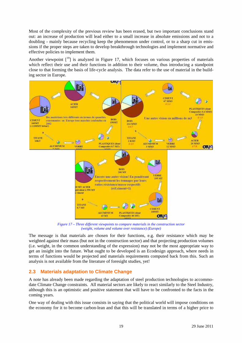
As a summary of this section and to shed some simple light in the complex storyline that has been told, a simple model updated from [17] has been worked out. It is based on the following assumptions, which mirror the content of this chapter but oversimplify it for the benefit of making some important points (cf. Figure 16):
• steel production in 2010 is assumed to be 1,300 Mt of crude steel, 30% produced by the EAF and 70% by the integrated route. Average emissions are 1.8 tCO2/tcrude steel and 0.6 and 2.3 re-spectively for each route.
• in 2050, steel production is supposed to have doubled, i.e. reach 2,600 Mt, with 60% produced by the EAF and 40% by the integrated route. Average emissions depend on scenarios:
o a trend scenario assumes that emissions are cut by 15%, based mainly on more adop-tion of advanced technologies (like BAT) and some more energy savings (1.1/0.5/1.9 tCO2/tcrude steel).
o a factor 4 scenario, called "Low Carbon" (LC) assumes that technologies are available and policies have been designed and applied in such a way that global emissions are cut by a factor 4 as compared to 2010 (0.2/0.1/0.4 tCO2/tcrude steel). This is a prescriptive scenario. It cannot be achieved with the CCS based ULCOS technologies as presented today and needs either the use of biomass in large quantities (like in [18]) or new tech-nologies or more simply applying CCS to ALL the smokestacks of the Steel Mills.
0
500
1000
1500
2000
2500
3000
2010 2050 trend 2050 LC
Steel production (Mt/yr)
CO2 generation (Mt/yr)
Figure 16 – simplified projections of CO2 emission sin the Steel sector
19 29 June 2011
Most of the complexity of the previous review has been erased, but two important conclusions stand out: an increase of production will lead either to a small increase in absolute emissions and not to a doubling - mainly because recycling keep the phenomenon under control, or to a sharp cut in emis-sions if the proper steps are taken to develop breakthrough technologies and implement normative and effective policies to implement them.
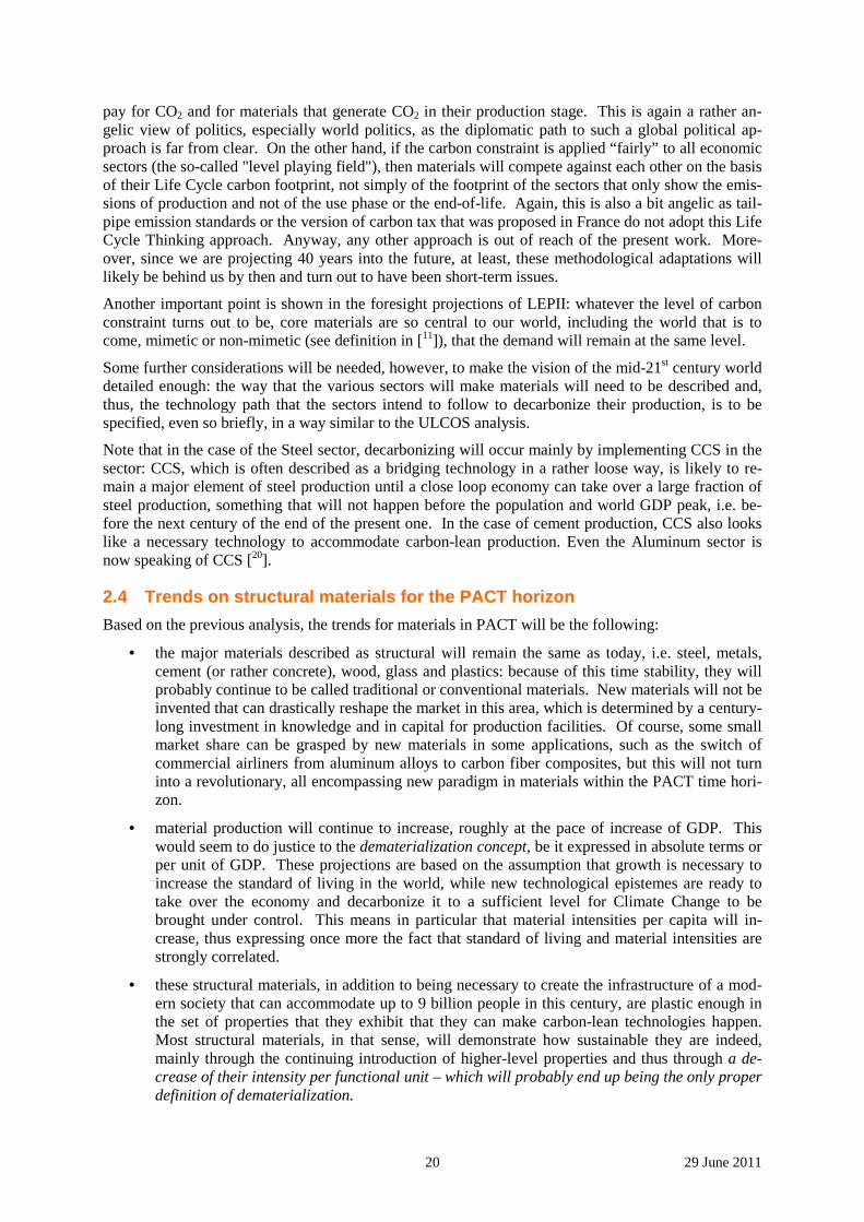
Another viewpoint [19] is analyzed in Figure 17, which focuses on various properties of materials which reflect their use and their functions in addition to their volume, thus introducing a standpoint close to that forming the basis of life-cycle analysis. The data refer to the use of material in the build-ing sector in Europe.
Figure 17 – Three different viewpoints to compare materials in the construction sector
(weight, volume and volume over resistance) (Europe)
The message is that materials are chosen for their functions, e.g. their resistance which may be weighted against their mass (but not in the construction sector) and that projecting production volumes (i.e. weight, in the common understanding of the expression) may not be the most appropriate way to get an insight into the future. What ought to be developed is an Ecodesign approach, where needs in terms of functions would be projected and materials requirements computed back from this. Such an analysis is not available from the literature of foresight studies, yet!
2.3 Materials adaptation to Climate Change
A note has already been made regarding the adaptation of steel production technologies to accommo-date Climate Change constraints. All material sectors are likely to react similarly to the Steel Industry, although this is an optimistic and positive statement that will have to be confronted to the facts in the coming years.
One way of dealing with this issue consists in saying that the political world will impose conditions on the economy for it to become carbon-lean and that this will be translated in terms of a higher price to
20 29 June 2011
pay for CO2 and for materials that generate CO2 in their production stage. This is again a rather an-gelic view of politics, especially world politics, as the diplomatic path to such a global political ap-proach is far from clear. On the other hand, if the carbon constraint is applied “fairly” to all economic sectors (the so-called "level playing field"), then materials will compete against each other on the basis of their Life Cycle carbon footprint, not simply of the footprint of the sectors that only show the emis-sions of production and not of the use phase or the end-of-life. Again, this is also a bit angelic as tail-pipe emission standards or the version of carbon tax that was proposed in France do not adopt this Life Cycle Thinking approach. Anyway, any other approach is out of reach of the present work. More-over, since we are projecting 40 years into the future, at least, these methodological adaptations will likely be behind us by then and turn out to have been short-term issues.
Another important point is shown in the foresight projections of LEPII: whatever the level of carbon constraint turns out to be, core materials are so central to our world, including the world that is to come, mimetic or non-mimetic (see definition in [11]), that the demand will remain at the same level.
Some further considerations will be needed, however, to make the vision of the mid-21st century world detailed enough: the way that the various sectors will make materials will need to be described and, thus, the technology path that the sectors intend to follow to decarbonize their production, is to be specified, even so briefly, in a way similar to the ULCOS analysis.
Note that in the case of the Steel sector, decarbonizing will occur mainly by implementing CCS in the sector: CCS, which is often described as a bridging technology in a rather loose way, is likely to re-main a major element of steel production until a close loop economy can take over a large fraction of steel production, something that will not happen before the population and world GDP peak, i.e. be-fore the next century of the end of the present one. In the case of cement production, CCS also looks like a necessary technology to accommodate carbon-lean production. Even the Aluminum sector is now speaking of CCS [20].
2.4 Trends on structural materials for the PACT horizon
Based on the previous analysis, the trends for materials in PACT will be the following:
• the major materials described as structural will remain the same as today, i.e. steel, metals, cement (or rather concrete), wood, glass and plastics: because of this time stability, they will probably continue to be called traditional or conventional materials. New materials will not be invented that can drastically reshape the market in this area, which is determined by a century-long investment in knowledge and in capital for production facilities. Of course, some small market share can be grasped by new materials in some applications, such as the switch of commercial airliners from aluminum alloys to carbon fiber composites, but this will not turn into a revolutionary, all encompassing new paradigm in materials within the PACT time hori-zon.
• material production will continue to increase, roughly at the pace of increase of GDP. This would seem to do justice to the dematerialization concept, be it expressed in absolute terms or per unit of GDP. These projections are based on the assumption that growth is necessary to increase the standard of living in the world, while new technological epistemes are ready to take over the economy and decarbonize it to a sufficient level for Climate Change to be brought under control. This means in particular that material intensities per capita will in-crease, thus expressing once more the fact that standard of living and material intensities are strongly correlated.
• these structural materials, in addition to being necessary to create the infrastructure of a mod-ern society that can accommodate up to 9 billion people in this century, are plastic enough in the set of properties that they exhibit that they can make carbon-lean technologies happen. Most structural materials, in that sense, will demonstrate how sustainable they are indeed, mainly through the continuing introduction of higher-level properties and thus through a de-crease of their intensity per functional unit – which will probably end up being the only proper definition of dematerialization.

21 29 June 2011
This vision may be different from that projected in other circles, where new materials are seen as the new frontier separating the present from some Eldorado future, as the revolution to come or already in the making, as the new direction in which society will move, including in the field of structural mate-rials. The promise of these new materials, apart from having been restated regularly over the last fifty years on the basis of new classes of materials, is often described as a renewal of the material offer and as the waning of conventional materials: the buzz words today are nanomaterials, nanostructures, nanodevices and nanosystems [21]. When this is transposed to structural materials, it is mainly hype, sometimes even science fiction [22, 23] 5. Governments have pushed very strongly to promote nano-technology, led by the Clinton administration in the US and then followed by Asia and Europe. The storyline today, however, focuses more on new design principles and on new ways of teaching the sci-ence of matter in universities than on the prediction of a radical shift in structural material paradigms.
5 The storyline of how a material with the maximum theoretical strength can be actually made has been cleverly used by Arthur C. Clarke to explain how a space elevator would actually be built!
22 29 June 2011
3 Qualitative description of materials use in society This section explores the connection between a post-carbon society and the artefacts that are used to fulfill its social services in terms of materials needs.
It may be covering grounds that other work packages also tackle, hopefully without contradicting them.
The approach is necessarily qualitative, as the scenario construction which will be one of the key parts of PACT has not been carried out yet. The post-carbon society is seen in a loose way as a desirable transformation of our present world, a kind of intellectual thought experiment.
What is said here is tentative and intuitive. It will need to be further reviewed when the full PACT approach is fleshed out.
We have tried to project a post-carbon scenario, which is radically unrelated to the present situation and not simply a business as usual (BAU) projection. Assumptions have been stated below in order to provide food for thought. Of course, this intuitive projection shortcuts a lot of complex debates based on the intrinsic uncertainty of future studies and a plain lack of vision in many areas, for example con-cerning agrofuels and land usage.
Production technologies are used to make the artefacts which will be needed by society and people.
Artefacts are of course made of materials, and, as stated in the introduction to this section, the focus is on the following materials, consistently to what has been stated in the introduction:
- Concrete, and cement or mineral materials for construction
- Glass, conventional and technical
- Metals, ferrous (mainly steel) and non-ferrous
- Plastics and carbon fibers-reinforced matrixes
- Wood.
Social services considered here are the followings (from VLEEM's classification):
• Mobility o Passengers o Freight
• Building and shelter o Construction o Maintenance o Thermal and sanitary comfort o Lighting
This section will identify the key drivers that will cause the change over from today's society to the post-carbon one. Then mobility and housing will be discussed separately, with a rationale covering drivers, technologies, infrastructure and materials.
3.1 Images of the post-carbon society and key drivers If we remember that PACT is targeting a desirable post-carbon society, we should state some general assumptions that will help us frame something between utopia and a likely desirable world, thus giv-ing clues for an estimate of the material demand.
3.1.1 Economic and social stability
In 2050, the World must be globally peaceful, provide food, health and well-being to a large part of the population.
23 29 June 2011
Short of that, we would have to use crisis analysis approaches, which are only beginning to be applied to this kind of studies and are out of scope of the work we can carry out here. For example, if rare elements, necessary for electric vehicles batteries or hydrogen fuel cells, are not available on the mar-ket due to a disturbed and unstable world, sustainable mobility would be compromised. Another as-sumption concerns the global warming actual effects in 2050: indeed, at that time, there is no doubt that some visible effects will be obvious, even if the strongest corrective actions were implemented starting from today [24]; this could jeopardize for example water availability or housing technologies generating a high energy demand for cooling…
In the field of social acceptance of technologies and regulations, it is also necessary to assume that people already have or will quickly demonstrate a high-level of consciousness regarding both risks and duties related to the abatement of CO2 emissions.
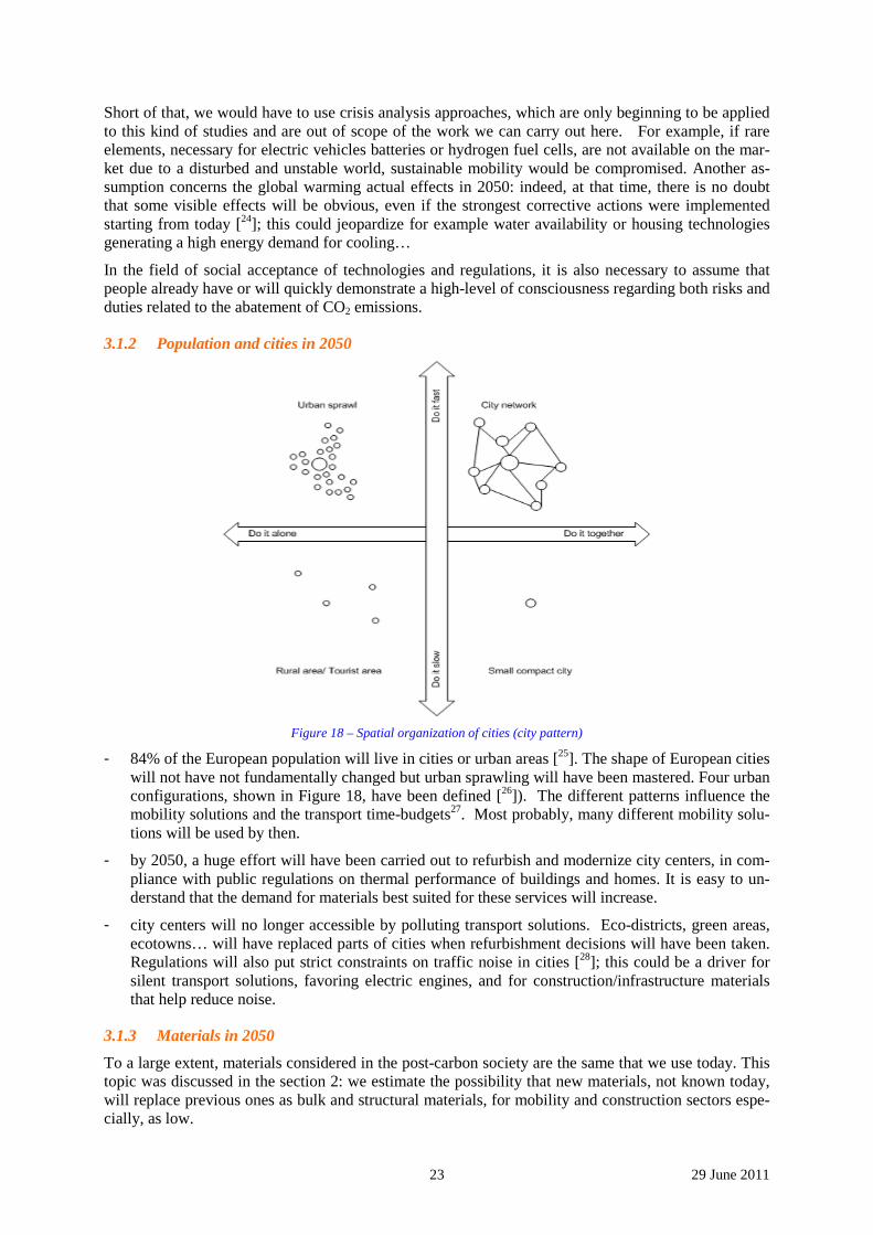
3.1.2 Population and cities in 2050
Figure 18 – Spatial organization of cities (city pattern)
- 84% of the European population will live in cities or urban areas [25]. The shape of European cities will not have not fundamentally changed but urban sprawling will have been mastered. Four urban configurations, shown in Figure 18, have been defined [26]). The different patterns influence the mobility solutions and the transport time-budgets27. Most probably, many different mobility solu-tions will be used by then.
- by 2050, a huge effort will have been carried out to refurbish and modernize city centers, in com-pliance with public regulations on thermal performance of buildings and homes. It is easy to un-derstand that the demand for materials best suited for these services will increase.
- city centers will no longer accessible by polluting transport solutions. Eco-districts, green areas, ecotowns… will have replaced parts of cities when refurbishment decisions will have been taken. Regulations will also put strict constraints on traffic noise in cities [28]; this could be a driver for silent transport solutions, favoring electric engines, and for construction/infrastructure materials that help reduce noise.
3.1.3 Materials in 2050
To a large extent, materials considered in the post-carbon society are the same that we use today. This topic was discussed in the section 2: we estimate the possibility that new materials, not known today, will replace previous ones as bulk and structural materials, for mobility and construction sectors espe-cially, as low.
24 29 June 2011
Here the issue of nanomaterials comes up. Although it is completely impossible that they replace bulk materials, it is important to keep them in mind because some bulk materials could have their intrinsic properties improved by embedding nano-elements in them [29]. But there are controversial issues about their toxicological nature: for the moment, we leave this issue open for experts.
3.1.4 An economy putting a strong emphasis on recycling in 2050
The world population is expected to exceed 9 billion by 2050. This increase, by roughly a third from 6.8 billion in 2009, will have a huge impact on global resources. Therefore, a sustainable society is one which uses fewer resources and energy due to this population-constrained context. This is impor-tant for resource savings and is a strong incentive towards a recycling economy30.
Recycling is to become a strong paradigm of the 2050 post-carbon materials scenario, to a greater ex-tend than it is today. The rationale is that the primary routes for material production are several times more energy-intensive than secondary routes and that they destroy rather than preserve resources. This greater emphasis on recycling is what should be understood as a closed-loop production system, although we have discussed elsewhere in this deliverable the limits that should be imposed to the con-cept. (cf. section 5 in page 63): some materials are already very highly recycled and thus do not pro-vide much leeway to improve recycling compared to the present situation (e.g. steel), and material demand will continue to increase beyond 2050, so that a society completely based on recycling will not emerge at this time horizon.
Recycling has a kind of inside dimension, related to the fact that a material can be easily recycled ei-ther once or indefinitely. Metals in general can be recycled, while many plastics cannot. However, indefinite recycling, which means reusing the material exactly for the same applications, is not very common. Only pure material are easy to recycle indefinitely, which is the case of carbon steels and pure aluminum, for example. Very alloyed metals can also be indefinitely recycled, if a proper recov-ery system is set up to collect them at the source and do it at each recycling step: this is the case for stainless steels, for example, for tool steel, etc31. If materials are not indefinitely recycled, then they entered a downgrading spiral.
From the standpoint of PACT, the need for materials to be recyclable and actually recycled has to be taken on board and contrasted to the statements regarding light materials (cf. again the caveats ex-pressed in section 5).
From the standpoint of European regulations, it is expected that landfilled waste must be halved from 2002 level. It is clear the post-carbon society needs materials that can be recycled or valorized at their end-of-life. For example, the European Directive 2000/53/CE on end-of-life vehicles imposes to recy-cle or valorize 95% of the vehicle mass by 2015; this constraint could have a significant impact on some materials if these cannot help car makers achieve the goal, and material shares in a car could change in favor of recyclable materials, modifying the trends we have today [32].
3.1.5 Energy in 2050
- energy will mainly stem from nuclear power and renewables, with hydrogen complementing electricity as an energy vector. The rationale is that CO2 and other pollutants will be strongly limited by environmental regulations. As an energy carrier, electricity will exhibit a large share of final energy demand for all services, as the VLEEM project has already pointed out [33].
- peak oil will have passed by then, as the year 2050 seems indeed to be an upper bound for this phenomenon [34,35]. The use of fossil fuel for mobility needs will by then have become mar-ginal. Electric or hybrid or hydrogen-based vehicles will called for.
- many issues remain controversial, especially concerning bio or agrofuels, as their environ-mental footprint is unclear, whether they are 1st, 2nd or 3rd generation. Moreover, they ought not to be allowed to compete with land needed for growing foodstuff or to replace forests. Some level of biofuels will be used [33].
25 29 June 2011
- energy production will have decarbonized. According to PACT assumptions and guidelines, at horizon 2050, fossil fuels will no longer be dominant and will have been replaced by non fos-sil energies, assuming that low-CO2 technologies for services have successfully been devel-oped. This means that energy is drawn from nuclear (conventional and maybe fusion), wind, hydropower, solar, biomass. All these energies are used together, interconnected when the carrier is electricity and controlled by smart-grids [36].
o nuclear power is a very sensitive matter, because it is very CO2-lean while it gener-ates problematic wastes and raises safety issues. The PACT hypothesis of a post-carbon society that does not use fossil fuels at the 2050 horizon, and which resorts only marginally to CCS, implicitly assumes that nuclear energy (present generation II reactors and next generations, III, III ½ and possibly IV or even V) will grasp an im-portant share of the grid. Moreover, 2050 might be the time for transition to fusion nuclear energy [37,38];should this be the case, scenarios of industrial deployment will have to be imagined to take into account nuclear fusion technologies. This build up of nuclear capacity will increase material demand in this sector.
o solar energy. It is an unlimited energy resource and, as such, will be widely deployed [39]. The technology portfolio is abundant and hopefully, scaling up and moving along the learning curve should remove the gap between kWh cost compared to stan-dard production. Demand for materials is impacted.
o wind. Denmark has demonstrated that wind power can be used to a high proportion of grid power, as 22% of national consumption stemmed from wind in 2007 [40]. Wind power will therefore develop, as part of the electricity grid and as local initiatives (homes, individual buildings, eco-areas), and call for material to build new equipment and to take care of a heavy maintenance and necessary refurbishment.
o hydropower is mentioned here as a reminder. Indeed, the availability of hydropower might decrease by 2050 as a consequence of climate change [41]. Therefore, no visible material demand will emerge from this sector.
o it is worth mentioning, though, that some applications of fossil fuels, like coal used as reducing agent in the steel industry, will still be used as a major energy source by 2050. Climate Change will be dealt with in this case by implementing CCS (cf. UL-COS technologies).
3.1.6 Information technologies
Communication and information technologies will be widely implemented in all social, technical and processing activities, where information and control will be important. They will have to be taken into account as they induce a demand for materials for small but numerous communicating artefacts and servers/network infrastructures, production processes, safety environments, etc. This will generate material demand.
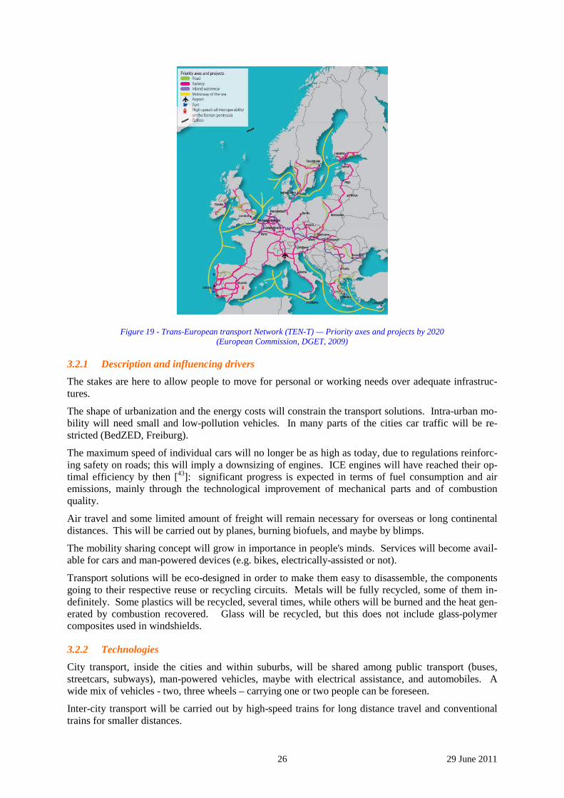
3.2 Mobility By 2050, it is assumed that the transport infrastructure in Europe will have fully matured and thus stopped growing (roads, highways, rail, air, sea and inland waterways). The TEN-T European project [42] gives an image of that infrastructure. Materials needs, beyond 2050, will be only related to the maintenance of the networks.
26 29 June 2011
Figure 19 - Trans-European transport Network (TEN-T) — Priority axes and projects by 2020 (European Commission, DGET, 2009)
3.2.1 Description and influencing drivers
The stakes are here to allow people to move for personal or working needs over adequate infrastruc-tures.
The shape of urbanization and the energy costs will constrain the transport solutions. Intra-urban mo-bility will need small and low-pollution vehicles. In many parts of the cities car traffic will be re-stricted (BedZED, Freiburg).
The maximum speed of individual cars will no longer be as high as today, due to regulations reinforc-ing safety on roads; this will imply a downsizing of engines. ICE engines will have reached their op-timal efficiency by then [43]: significant progress is expected in terms of fuel consumption and air emissions, mainly through the technological improvement of mechanical parts and of combustion quality.
Air travel and some limited amount of freight will remain necessary for overseas or long continental distances. This will be carried out by planes, burning biofuels, and maybe by blimps.
The mobility sharing concept will grow in importance in people's minds. Services will become avail-able for cars and man-powered devices (e.g. bikes, electrically-assisted or not).
Transport solutions will be eco-designed in order to make them easy to disassemble, the components going to their respective reuse or recycling circuits. Metals will be fully recycled, some of them in-definitely. Some plastics will be recycled, several times, while others will be burned and the heat gen-erated by combustion recovered. Glass will be recycled, but this does not include glass-polymer composites used in windshields.
3.2.2 Technologies
City transport, inside the cities and within suburbs, will be shared among public transport (buses, streetcars, subways), man-powered vehicles, maybe with electrical assistance, and automobiles. A wide mix of vehicles - two, three wheels – carrying one or two people can be foreseen.
Inter-city transport will be carried out by high-speed trains for long distance travel and conventional trains for smaller distances.
27 29 June 2011
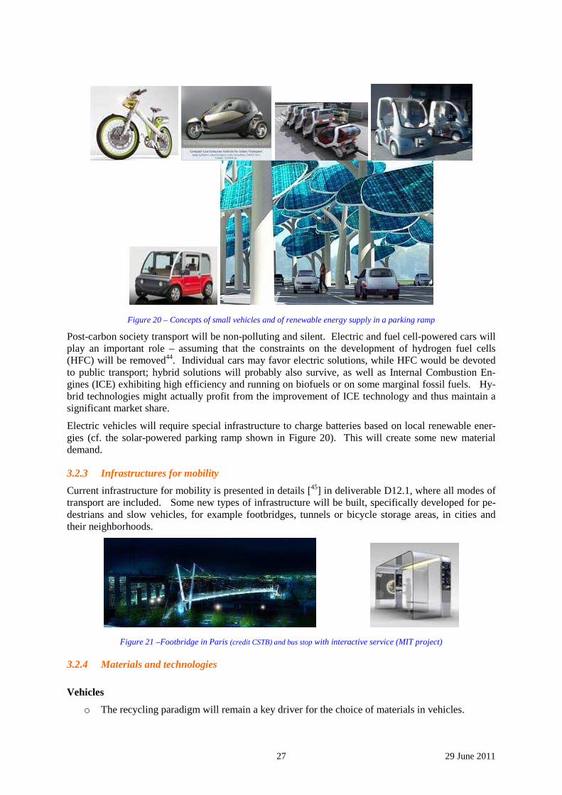
Figure 20 – Concepts of small vehicles and of renewable energy supply in a parking ramp
Post-carbon society transport will be non-polluting and silent. Electric and fuel cell-powered cars will play an important role – assuming that the constraints on the development of hydrogen fuel cells (HFC) will be removed44. Individual cars may favor electric solutions, while HFC would be devoted to public transport; hybrid solutions will probably also survive, as well as Internal Combustion En-gines (ICE) exhibiting high efficiency and running on biofuels or on some marginal fossil fuels. Hy-brid technologies might actually profit from the improvement of ICE technology and thus maintain a significant market share.
Electric vehicles will require special infrastructure to charge batteries based on local renewable ener-gies (cf. the solar-powered parking ramp shown in Figure 20). This will create some new material demand.
3.2.3 Infrastructures for mobility
Current infrastructure for mobility is presented in details [45] in deliverable D12.1, where all modes of transport are included. Some new types of infrastructure will be built, specifically developed for pe-destrians and slow vehicles, for example footbridges, tunnels or bicycle storage areas, in cities and their neighborhoods.
Figure 21 –Footbridge in Paris (credit CSTB) and bus stop with interactive service (MIT project)
3.2.4 Materials and technologies
Vehicles
o The recycling paradigm will remain a key driver for the choice of materials in vehicles.
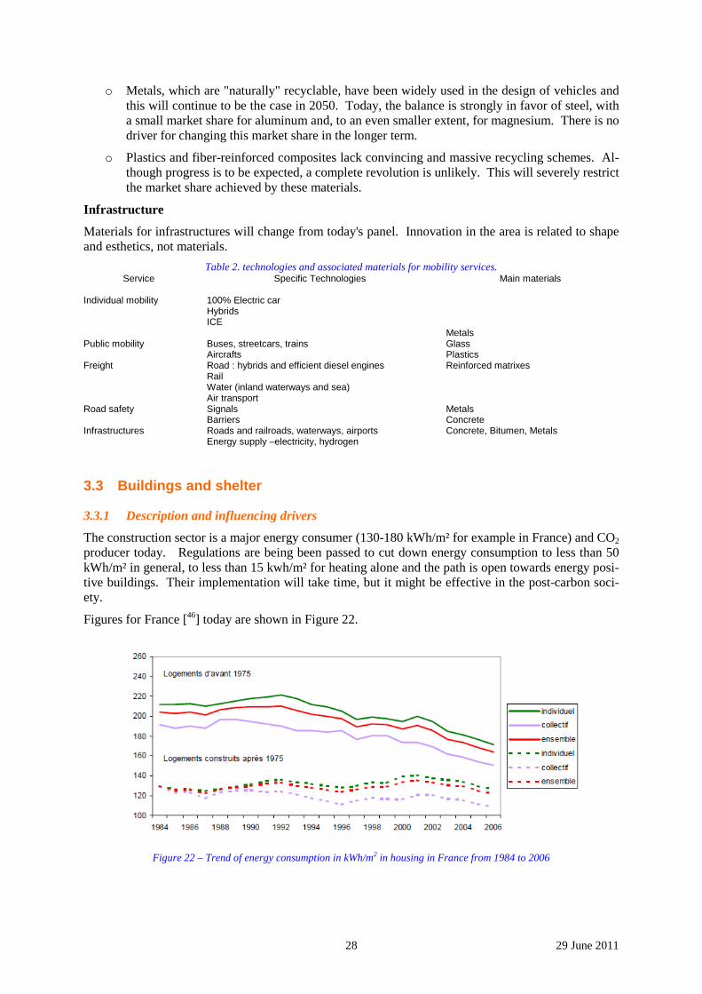
28 29 June 2011
o Metals, which are "naturally" recyclable, have been widely used in the design of vehicles and this will continue to be the case in 2050. Today, the balance is strongly in favor of steel, with a small market share for aluminum and, to an even smaller extent, for magnesium. There is no driver for changing this market share in the longer term.
o Plastics and fiber-reinforced composites lack convincing and massive recycling schemes. Al-though progress is to be expected, a complete revolution is unlikely. This will severely restrict the market share achieved by these materials.
Infrastructure
Materials for infrastructures will change from today's panel. Innovation in the area is related to shape and esthetics, not materials.
Table 2. technologies and associated materials for mobility services. Service Specific Technologies Main materials
Individual mobility 100% Electric car
Hybrids ICE
Public mobility Buses, streetcars, trains Aircrafts
Freight Road : hybrids and efficient diesel engines Rail Water (inland waterways and sea) Air transport
Metals Glass Plastics Reinforced matrixes
Road safety Signals Barriers
Metals Concrete
Infrastructures Roads and railroads, waterways, airports Energy supply –electricity, hydrogen
Concrete, Bitumen, Metals
3.3 Buildings and shelter
3.3.1 Description and influencing drivers
The construction sector is a major energy consumer (130-180 kWh/m² for example in France) and CO2 producer today. Regulations are being been passed to cut down energy consumption to less than 50 kWh/m² in general, to less than 15 kwh/m² for heating alone and the path is open towards energy posi-tive buildings. Their implementation will take time, but it might be effective in the post-carbon soci-ety.
Figures for France [46] today are shown in Figure 22.
Figure 22 – Trend of energy consumption in kWh/m2 in housing in France from 1984 to 2006
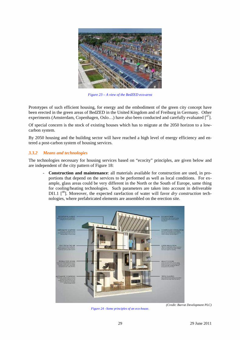
29 29 June 2011
Figure 23 – A view of the BedZED eco-area
Prototypes of such efficient housing, for energy and the embodiment of the green city concept have been erected in the green areas of BedZED in the United Kingdom and of Freiburg in Germany. Other experiments (Amsterdam, Copenhagen, Oslo…) have also been conducted and carefully evaluated [47].
Of special concern is the stock of existing houses which has to migrate at the 2050 horizon to a low-carbon system.
By 2050 housing and the building sector will have reached a high level of energy efficiency and en-tered a post-carbon system of housing services.
3.3.2 Means and technologies
The technologies necessary for housing services based on “ecocity” principles, are given below and are independent of the city pattern of Figure 18:
- Construction and maintenance: all materials available for construction are used, in pro-portions that depend on the services to be performed as well as local conditions. For ex-ample, glass areas could be very different in the North or the South of Europe, same thing for cooling/heating technologies. Such parameters are taken into account in deliverable DI1.1 [48]. Moreover, the expected rarefaction of water will favor dry construction tech-nologies, where prefabricated elements are assembled on the erection site.
(Credit: Barrat Development PLC)
Figure 24 –Some principles of an eco-house.
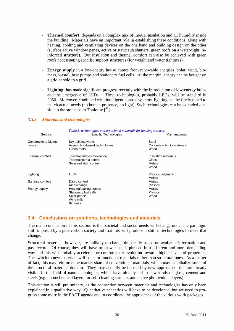
30 29 June 2011
- Thermal comfort: depends on a complex mix of inertia, insulation and air humidity inside
the building. Materials have an important role in establishing these conditions, along with heating, cooling and ventilating devices on the one hand and building design on the other (surface active window panes, active or static sun shutters, green roofs on a water-tight, re-inforced structure). But insulation and thermal comfort can also be achieved with green roofs necessitating specific support structures (for weight and water tightness).
- Energy supply in a low-energy house comes from renewable energies (solar, wind, bio-
mass, waste), heat pumps and stationary fuel cells. At the margin, energy can be bought on a grid or sold to a grid.
- Lighting: has made significant progress recently with the introduction of low-energy bulbs
and the emergence of LEDs. These technologies, probably LEDs, will be standard in 2050. Moreover, combined with intelligent control systems, lighting can be finely tuned to match actual needs (no human presence, no light). Such technologies can be extended out-side to the street, as in Toulouse [49].
3.3.3 Materials and technologies
Table 3. technologies and associated materials for housing services.
Service Specific Technologies Main materials Construction / Mainte-nance
Dry building works Assembling-based technologies Green roofs
Steel Concrete – bricks – stones Wood
Thermal comfort Thermal bridges avoidance Thermal inertia control Solar radiation control
Insulation materials Glass Metals Wood
Lighting LEDs Plastics/polymers Metals
Sanitary comfort Damp control Air exchange
Metals Plastics
Energy supply Heating/cooling pumps Stationary fuel cells Solar panels Wind mills Biomass
Metals Plastics Wood
3.4 Conclusions on solutions, technologies and materials
The main conclusion of this section is that societal and social needs will change under the paradigm shift imposed by a post-carbon society and that this will produce a shift in technologies to meet that change.
Structural materials, however, are unlikely to change drastically based on available information and past record. Of course, they will have to answer needs phrased in a different and more demanding way and this will probably accelerate or comfort their evolution towards higher levels of properties. The switch to new materials will concern functional materials rather than structural ones. As a matter of fact, this may reinforce the market share of conventional materials, which may cannibalize some of the structural materials domain. They may actually be boosted by new approaches: this are already visible in the field of nanotechnologies, which have already led to new kinds of glass, cement and steels (e.g. photochemical layers for self-cleaning surfaces and active photovoltaic layers).
This section is still preliminary, as the connection between materials and technologies has only been explained in a qualitative way. Quantitative scenarios will have to be developed, but we need to pro-gress some more in the PACT agenda and to coordinate the approaches of the various work packages.
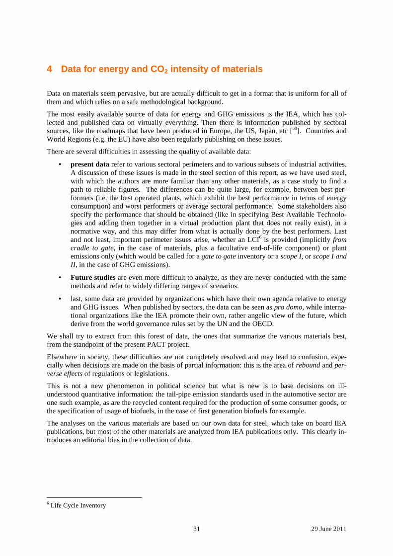
31 29 June 2011
4 Data for energy and CO2 intensity of materials
Data on materials seem pervasive, but are actually difficult to get in a format that is uniform for all of them and which relies on a safe methodological background.
The most easily available source of data for energy and GHG emissions is the IEA, which has col-lected and published data on virtually everything. Then there is information published by sectoral sources, like the roadmaps that have been produced in Europe, the US, Japan, etc [50]. Countries and World Regions (e.g. the EU) have also been regularly publishing on these issues.
There are several difficulties in assessing the quality of available data:
• present data refer to various sectoral perimeters and to various subsets of industrial activities. A discussion of these issues is made in the steel section of this report, as we have used steel, with which the authors are more familiar than any other materials, as a case study to find a path to reliable figures. The differences can be quite large, for example, between best per-formers (i.e. the best operated plants, which exhibit the best performance in terms of energy consumption) and worst performers or average sectoral performance. Some stakeholders also specify the performance that should be obtained (like in specifying Best Available Technolo-gies and adding them together in a virtual production plant that does not really exist), in a normative way, and this may differ from what is actually done by the best performers. Last and not least, important perimeter issues arise, whether an LCI6 is provided (implicitly from cradle to gate, in the case of materials, plus a facultative end-of-life component) or plant emissions only (which would be called for a gate to gate inventory or a scope I, or scope I and II, in the case of GHG emissions).
• Future studies are even more difficult to analyze, as they are never conducted with the same methods and refer to widely differing ranges of scenarios.
• last, some data are provided by organizations which have their own agenda relative to energy and GHG issues. When published by sectors, the data can be seen as pro domo, while interna-tional organizations like the IEA promote their own, rather angelic view of the future, which derive from the world governance rules set by the UN and the OECD.
We shall try to extract from this forest of data, the ones that summarize the various materials best, from the standpoint of the present PACT project.
Elsewhere in society, these difficulties are not completely resolved and may lead to confusion, espe-cially when decisions are made on the basis of partial information: this is the area of rebound and per-verse effects of regulations or legislations.
This is not a new phenomenon in political science but what is new is to base decisions on ill-understood quantitative information: the tail-pipe emission standards used in the automotive sector are one such example, as are the recycled content required for the production of some consumer goods, or the specification of usage of biofuels, in the case of first generation biofuels for example.
The analyses on the various materials are based on our own data for steel, which take on board IEA publications, but most of the other materials are analyzed from IEA publications only. This clearly in-troduces an editorial bias in the collection of data.
6 Life Cycle Inventory
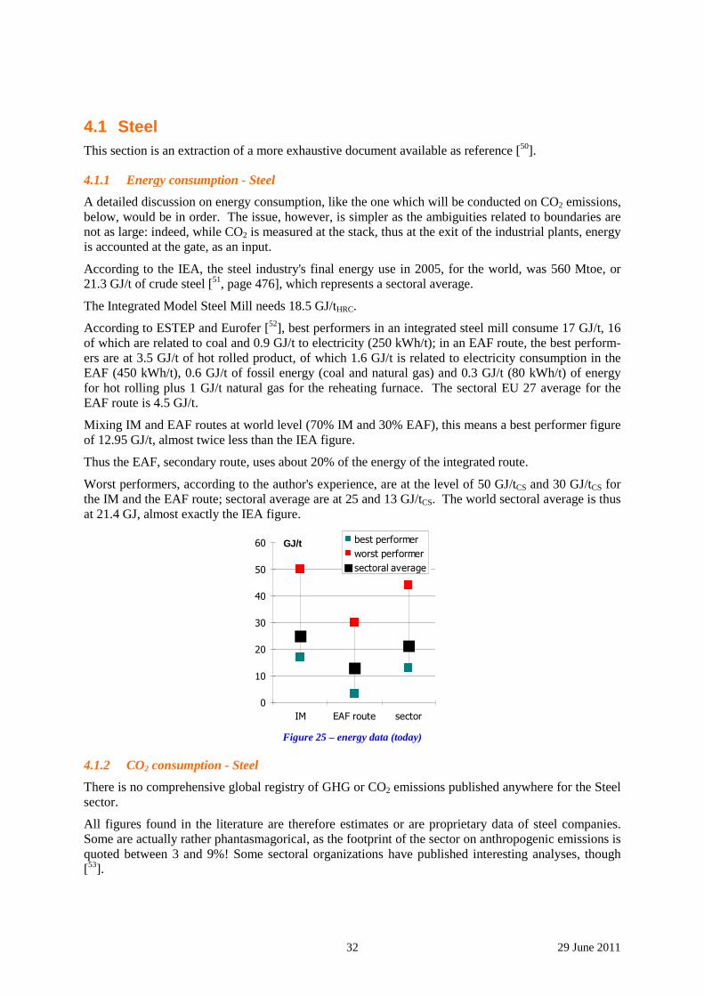
32 29 June 2011
4.1 Steel This section is an extraction of a more exhaustive document available as reference [50].
4.1.1 Energy consumption - Steel
A detailed discussion on energy consumption, like the one which will be conducted on CO2 emissions, below, would be in order. The issue, however, is simpler as the ambiguities related to boundaries are not as large: indeed, while CO2 is measured at the stack, thus at the exit of the industrial plants, energy is accounted at the gate, as an input.
According to the IEA, the steel industry's final energy use in 2005, for the world, was 560 Mtoe, or 21.3 GJ/t of crude steel [51, page 476], which represents a sectoral average.
The Integrated Model Steel Mill needs 18.5 GJ/tHRC.
According to ESTEP and Eurofer [52], best performers in an integrated steel mill consume 17 GJ/t, 16 of which are related to coal and 0.9 GJ/t to electricity (250 kWh/t); in an EAF route, the best perform-ers are at 3.5 GJ/t of hot rolled product, of which 1.6 GJ/t is related to electricity consumption in the EAF (450 kWh/t), 0.6 GJ/t of fossil energy (coal and natural gas) and 0.3 GJ/t (80 kWh/t) of energy for hot rolling plus 1 GJ/t natural gas for the reheating furnace. The sectoral EU 27 average for the EAF route is 4.5 GJ/t.
Mixing IM and EAF routes at world level (70% IM and 30% EAF), this means a best performer figure of 12.95 GJ/t, almost twice less than the IEA figure.
Thus the EAF, secondary route, uses about 20% of the energy of the integrated route.
Worst performers, according to the author's experience, are at the level of 50 GJ/tCS and 30 GJ/tCS for the IM and the EAF route; sectoral average are at 25 and 13 GJ/tCS. The world sectoral average is thus at 21.4 GJ, almost exactly the IEA figure.
0
10
20
30
40
50
60
IM EAF route sector
best performer
worst performer
sectoral average
GJ/t
Figure 25 – energy data (today)
4.1.2 CO2 consumption - Steel
There is no comprehensive global registry of GHG or CO2 emissions published anywhere for the Steel sector.
All figures found in the literature are therefore estimates or are proprietary data of steel companies. Some are actually rather phantasmagorical, as the footprint of the sector on anthropogenic emissions is quoted between 3 and 9%! Some sectoral organizations have published interesting analyses, though [53].
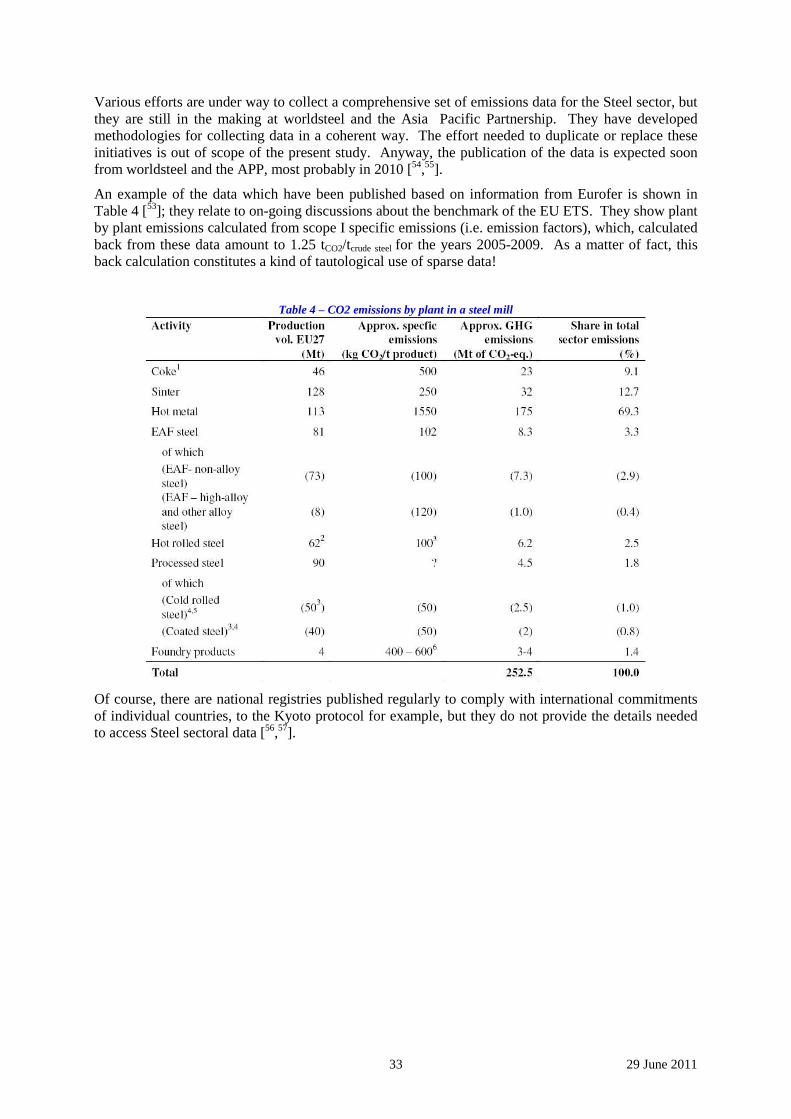
33 29 June 2011
Various efforts are under way to collect a comprehensive set of emissions data for the Steel sector, but they are still in the making at worldsteel and the Asia Pacific Partnership. They have developed methodologies for collecting data in a coherent way. The effort needed to duplicate or replace these initiatives is out of scope of the present study. Anyway, the publication of the data is expected soon from worldsteel and the APP, most probably in 2010 [54,55].
An example of the data which have been published based on information from Eurofer is shown in Table 4 [53]; they relate to on-going discussions about the benchmark of the EU ETS. They show plant by plant emissions calculated from scope I specific emissions (i.e. emission factors), which, calculated back from these data amount to 1.25 tCO2/tcrude steel for the years 2005-2009. As a matter of fact, this back calculation constitutes a kind of tautological use of sparse data!
Table 4 – CO2 emissions by plant in a steel mill
Of course, there are national registries published regularly to comply with international commitments of individual countries, to the Kyoto protocol for example, but they do not provide the details needed to access Steel sectoral data [56,57].
34 29 June 2011
Figure 26 – definition of the boundaries of the systems defined around a plant
by the Greenhouse Gas Protocol (scopes I, II and III)
Methodological issues ought now to be pointed out. Most of them relate to the boundaries of the sys-tem within which the CO2 emissions are accounted.
The Greenhouse Gas Protocol [58] has carried out an analysis in terms of scopes, shown in Figure 26, that has become a standard [59] and can simply be referred to as direct emissions (scope I), emissions related to energy production (scope II) and upstream and downstream emissions, including credits for co/by-products, for example (scope III). Thus an LCA database will contain scope I + II + III emis-sion data, while a registry for physical emissions from a production plant will contain scope I emis-sions; on the other hand, technologists interested in process engineering will be more interested in scope I + II data.
Another level of ambiguity is related to the kind of plants which are included in a steel mill, as some may have coke batteries or a lime kiln, or an oxygen plant, or a power plant to recover process gases and combust to generate electricity, and others not. There are no rules for these and therefore scope I data represent the actual direct emissions of the mills: it is hard to compare these individual data, unless the mill is fully described, but, on the other hand, this aggregation of emissions is representative of the emissions of a sector as a whole and they can readily be compared to other sectors, and the data aggregated with those of other sectors to build up a snapshot of world emissions.
Table 5 – examples of specific CO2 emissions (emission factors) for steel production source Scope I Scope II Scope I+II
tCO2/tcrude steel
Country A, global 1.67
IPCC 1.9
Country B 1.83 0.44 2.26
Source a Integrated route 2.0
Source a EAF route 0.15
Source a Steel sector 1.26
Still another difficulty is related to specific emissions, i.e. emissions normalized by production vol-ume. Usually, crude steel is used as the normalization factor, even though emissions for the whole steel mill are shown (thus emissions from gate to coil per ton of liquid steel).
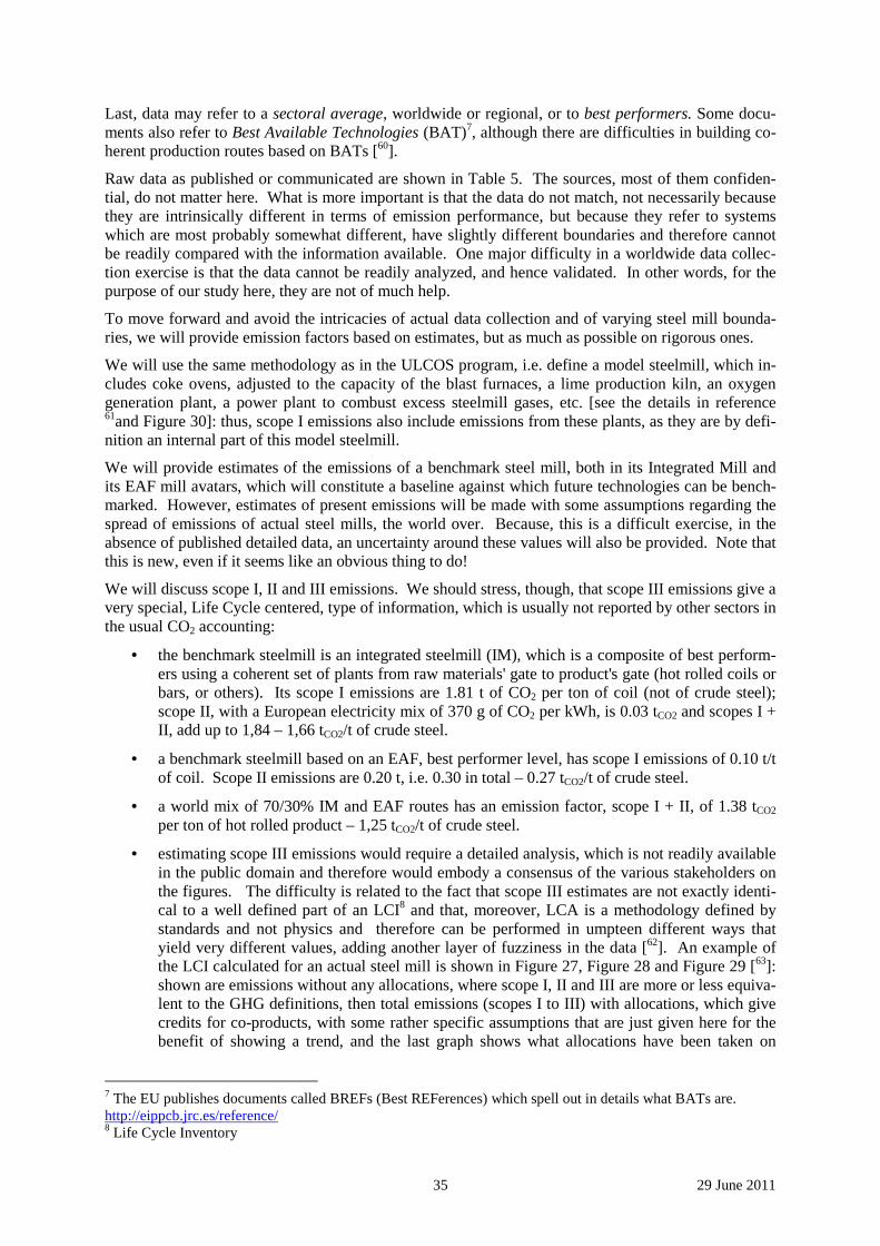
35 29 June 2011
Last, data may refer to a sectoral average, worldwide or regional, or to best performers. Some docu-ments also refer to Best Available Technologies (BAT)7, although there are difficulties in building co-herent production routes based on BATs [60].
Raw data as published or communicated are shown in Table 5. The sources, most of them confiden-tial, do not matter here. What is more important is that the data do not match, not necessarily because they are intrinsically different in terms of emission performance, but because they refer to systems which are most probably somewhat different, have slightly different boundaries and therefore cannot be readily compared with the information available. One major difficulty in a worldwide data collec-tion exercise is that the data cannot be readily analyzed, and hence validated. In other words, for the purpose of our study here, they are not of much help.
To move forward and avoid the intricacies of actual data collection and of varying steel mill bounda-ries, we will provide emission factors based on estimates, but as much as possible on rigorous ones.
We will use the same methodology as in the ULCOS program, i.e. define a model steelmill, which in-cludes coke ovens, adjusted to the capacity of the blast furnaces, a lime production kiln, an oxygen generation plant, a power plant to combust excess steelmill gases, etc. [see the details in reference 61and Figure 30]: thus, scope I emissions also include emissions from these plants, as they are by defi-nition an internal part of this model steelmill.
We will provide estimates of the emissions of a benchmark steel mill, both in its Integrated Mill and its EAF mill avatars, which will constitute a baseline against which future technologies can be bench-marked. However, estimates of present emissions will be made with some assumptions regarding the spread of emissions of actual steel mills, the world over. Because, this is a difficult exercise, in the absence of published detailed data, an uncertainty around these values will also be provided. Note that this is new, even if it seems like an obvious thing to do!
We will discuss scope I, II and III emissions. We should stress, though, that scope III emissions give a very special, Life Cycle centered, type of information, which is usually not reported by other sectors in the usual CO2 accounting:
• the benchmark steelmill is an integrated steelmill (IM), which is a composite of best perform-ers using a coherent set of plants from raw materials' gate to product's gate (hot rolled coils or bars, or others). Its scope I emissions are 1.81 t of CO2 per ton of coil (not of crude steel); scope II, with a European electricity mix of 370 g of CO2 per kWh, is 0.03 tCO2 and scopes I + II, add up to 1,84 – 1,66 tCO2/t of crude steel.
• a benchmark steelmill based on an EAF, best performer level, has scope I emissions of 0.10 t/t of coil. Scope II emissions are 0.20 t, i.e. 0.30 in total – 0.27 tCO2/t of crude steel.
• a world mix of 70/30% IM and EAF routes has an emission factor, scope I + II, of 1.38 tCO2 per ton of hot rolled product – 1,25 tCO2/t of crude steel.
• estimating scope III emissions would require a detailed analysis, which is not readily available in the public domain and therefore would embody a consensus of the various stakeholders on the figures. The difficulty is related to the fact that scope III estimates are not exactly identi-cal to a well defined part of an LCI8 and that, moreover, LCA is a methodology defined by standards and not physics and therefore can be performed in umpteen different ways that yield very different values, adding another layer of fuzziness in the data [62]. An example of the LCI calculated for an actual steel mill is shown in Figure 27, Figure 28 and Figure 29 [63]: shown are emissions without any allocations, where scope I, II and III are more or less equiva-lent to the GHG definitions, then total emissions (scopes I to III) with allocations, which give credits for co-products, with some rather specific assumptions that are just given here for the benefit of showing a trend, and the last graph shows what allocations have been taken on
7 The EU publishes documents called BREFs (Best REFerences) which spell out in details what BATs are. http://eippcb.jrc.es/reference/ 8 Life Cycle Inventory
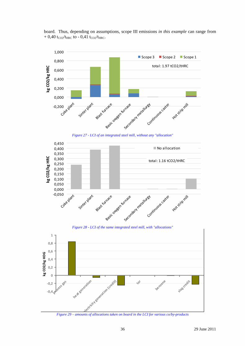
36 29 June 2011
board. Thus, depending on assumptions, scope III emissions in this example can range from + 0,40 tCO2/tHRC to - 0,41 tCO2/tHRC.
-0,200
0,000
0,200
0,400
0,600
0,800
1,000
Coke p
lant
Sinte
r pla
nt
Blast
furn
ace
Basic
oxy
gen fu
rnac
e
Seco
ndary
meta
llurg
y
Continuous
cas
ter
Hot str
ip m
ill
Scope 3 Scope 2 Scope 1
kg
CO
2/k
g H
RC total: 1.97 tCO2/tHRC
Figure 27 - LCI of an integrated steel mill, without any "allocation"
-0,050
0,000
0,050
0,100
0,150
0,200
0,250
0,300
0,350
0,400
0,450
Coke p
lant
Sinte
r pla
nt
Blast
furn
ace
Basic
oxy
gen fu
rnac
e
Seco
ndary
meta
llurg
y
Continuous
cas
ter
Hot str
ip m
ill
No allocation
kg
CO
2/k
g H
RC
total: 1.16 tCO2/tHRC
Figure 28 - LCI of the same integrated steel mill, with "allocations"
-0,4
-0,2
0
0,2
0,4
0,6
0,8
1
proce
ss g
as
heat g
eneratio
n
elect
ricit
y genera
tion (c
redit) ta
r
benzene
slag
credit
kg
CO
2/k
g H
DG
Figure 29 – amounts of allocations taken on board in the LCI for various co/by-products
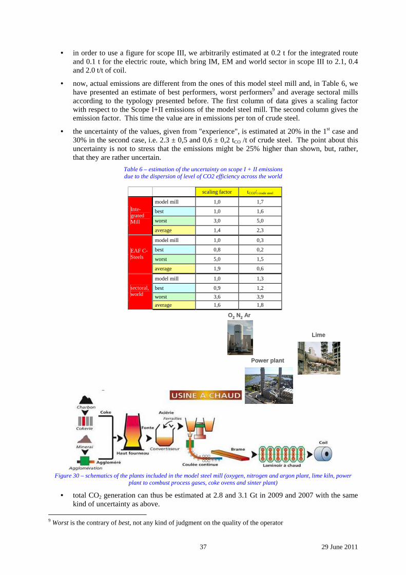
37 29 June 2011
• in order to use a figure for scope III, we arbitrarily estimated at 0.2 t for the integrated route and 0.1 t for the electric route, which bring IM, EM and world sector in scope III to 2.1, 0.4 and 2.0 t/t of coil.
• now, actual emissions are different from the ones of this model steel mill and, in Table 6, we have presented an estimate of best performers, worst performers9 and average sectoral mills according to the typology presented before. The first column of data gives a scaling factor with respect to the Scope I+II emissions of the model steel mill. The second column gives the emission factor. This time the value are in emissions per ton of crude steel.
• the uncertainty of the values, given from "experience", is estimated at 20% in the 1st case and 30% in the second case, i.e. 2.3 ± 0,5 and 0,6 ± 0,2 tCO /t of crude steel. The point about this uncertainty is not to stress that the emissions might be 25% higher than shown, but, rather, that they are rather uncertain.
Table 6 – estimation of the uncertainty on scope I + II emissions due to the dispersion of level of CO2 efficiency across the world
scaling factor tCO2/t crude steel
model mill 1,0 1,7
best 1,0 1,6
worst 3,0 5,0
Inte-grated Mill
average 1,4 2,3
model mill 1,0 0,3
best 0,8 0,2
worst 5,0 1,5
EAF C-Steels
average 1,9 0,6
model mill 1,0 1,3
best 0,9 1,2
worst 3,6 3,9
sectoral, world
average 1,6 1,8
O2 N2 ArO2 N2 Ar
LimeLime
Power plantPower plant
Figure 30 – schematics of the plants included in the model steel mill (oxygen, nitrogen and argon plant, lime kiln, power
plant to combust process gases, coke ovens and sinter plant)
• total CO2 generation can thus be estimated at 2.8 and 3.1 Gt in 2009 and 2007 with the same kind of uncertainty as above.
9 Worst is the contrary of best, not any kind of judgment on the quality of the operator
38 29 June 2011
The reader will have noticed that one major reason, among many, for the discrepancy between scope I, scope II and real physical emissions is the fact that steel mills do not always include the same plants, foremost of which is the power plant, which, in regions like Europe or Japan, are systematically built to recover the energy of the process gases not used inside the steel mill to reheat furnaces, ladles, etc., but may be part of the mill or constitute a separate activity contracted out to a utility company (cf. Figure 30). These details are business-based and not process-based and the aggregated emissions re-flect this "biodiversity" of steel mills, not necessarily causes of emissions on which action can be taken to reduce them: divesting the power plant from the steel mill to a utility does not erase the correspond-ing emissions, it simply shifts them to a different business entity.
If this is taken on board, then average emissions can range from 1.3 to 2.3 tCO2/tcrude steel an even larger bracket than the one mentioned before as an uncertainty on the data. It is part of the fuzziness of the data that are circulated around and used by various stakeholders, as are the scope III estimates, which would compound this further.
4.1.3 Foresight projections
Foresight studies for steel and other materials were presented under section 2.1.
The IM/EAF mix is assumed to switch from 70/30% today to 40/60% in 2050.
As far as energy is concerned, we have assumed a factor 4 (75%) drop in specific energy consumption for the steel sector, which amounts to a factor 3 reduction for each of the production routes: 14.4, 15.7 and 25 GJ/t for the best performers, sectoral average and worst performer in the case of the IM and 3.0, 3.8 and 7.5 for the EAF route. The world average thus becomes 7.6, 8.5 and 14.5 respectively.
CO2 projections are given at the end of section 2.1.
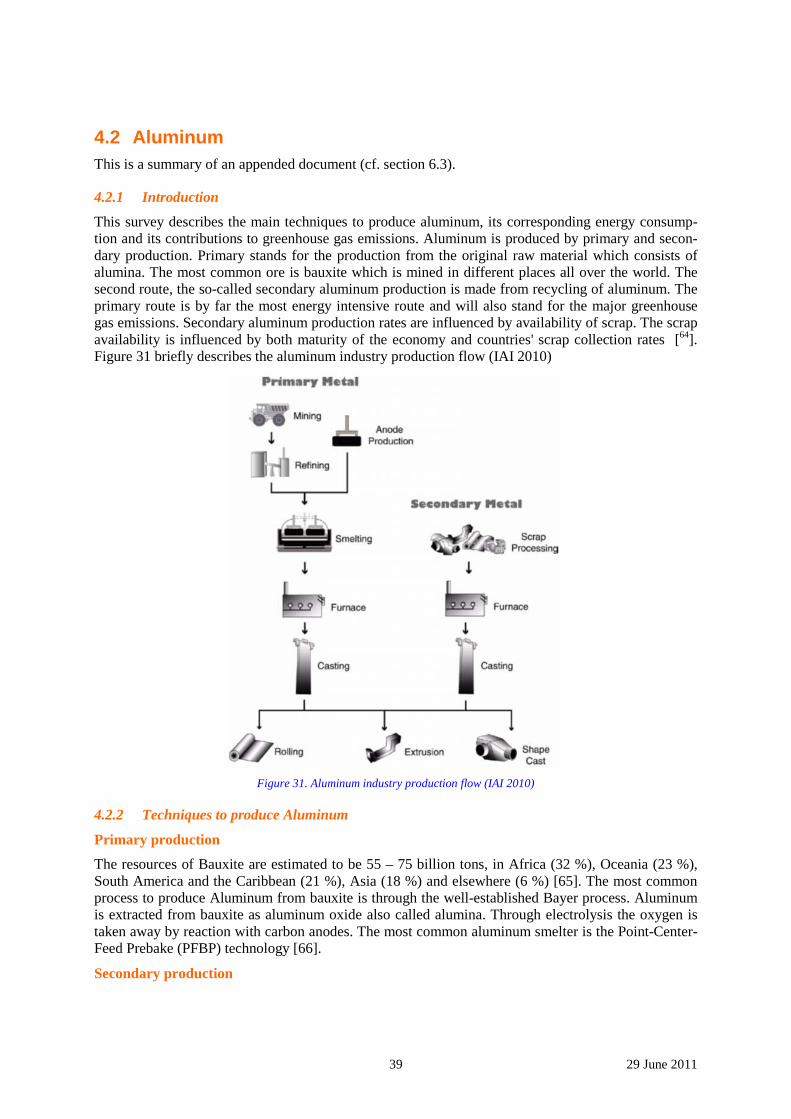
39 29 June 2011
4.2 Aluminum This is a summary of an appended document (cf. section 6.3).
4.2.1 Introduction
This survey describes the main techniques to produce aluminum, its corresponding energy consump-tion and its contributions to greenhouse gas emissions. Aluminum is produced by primary and secon-dary production. Primary stands for the production from the original raw material which consists of alumina. The most common ore is bauxite which is mined in different places all over the world. The second route, the so-called secondary aluminum production is made from recycling of aluminum. The primary route is by far the most energy intensive route and will also stand for the major greenhouse gas emissions. Secondary aluminum production rates are influenced by availability of scrap. The scrap availability is influenced by both maturity of the economy and countries' scrap collection rates [64]. Figure 31 briefly describes the aluminum industry production flow (IAI 2010)
Figure 31. Aluminum industry production flow (IAI 2010)
4.2.2 Techniques to produce Aluminum
Primary production
The resources of Bauxite are estimated to be 55 – 75 billion tons, in Africa (32 %), Oceania (23 %), South America and the Caribbean (21 %), Asia (18 %) and elsewhere (6 %) [65]. The most common process to produce Aluminum from bauxite is through the well-established Bayer process. Aluminum is extracted from bauxite as aluminum oxide also called alumina. Through electrolysis the oxygen is taken away by reaction with carbon anodes. The most common aluminum smelter is the Point-Center-Feed Prebake (PFBP) technology [66].
Secondary production
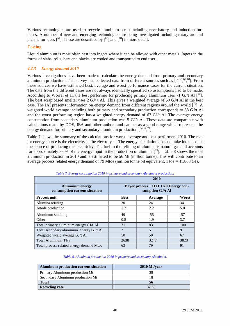
40 29 June 2011
Various technologies are used to recycle aluminum scrap including reverbatory and induction fur-naces. A number of new and emerging technologies are being investigated including rotary arc and plasma furnaces [64]. These are described by [67] and [68] in more detail.
Casting
Liquid aluminum is most often cast into ingots where it can be alloyed with other metals. Ingots in the forms of slabs, rolls, bars and blacks are cooled and transported to end user.
4.2.3 Energy demand 2010
Various investigations have been made to calculate the energy demand from primary and secondary aluminum production. This survey has collected data from different sources such as [64,65,67,68]. From these sources we have estimated best, average and worst performance cases for the current situation. The data from the different cases are not always identically specified so assumptions had to be made. According to Worrel et al. the best performer for producing primary aluminum uses 71 GJ/t Al [69]. The best scrap based smelter uses 2 GJ/ t Al. This gives a weighted average of 50 GJ/t Al in the best case. The IAI presents information on energy demand from different regions around the world [70]. A weighted world average including both primary and secondary production corresponds to 58 GJ/t Al and the worst performing region has a weighted energy demand of 67 GJ/t Al. The average energy consumption from secondary aluminum production was 5 GJ/t Al. These data are comparable with calculations made by DOE, IEA and other authors and can act as a good range which represents the energy demand for primary and secondary aluminum production [64,67,71].
Table 7 shows the summary of the calculations for worst, average and best performers 2010. The ma-jor energy source is the electricity in the electrolysis. The energy calculation does not take into account the source of producing this electricity. The fuel in the refining of alumina is natural gas and accounts for approximately 85 % of the energy input in the production of alumina [70]. Table 8 shows the total aluminum production in 2010 and is estimated to be 56 Mt (million tonne). This will contribute to an average process related energy demand of 79 Mtoe (million tonne oil equivalent, 1 toe = 41.868 GJ).
Table 7. Energy consumption 2010 in primary and secondary Aluminum production.
Table 8. Aluminum production 2010 in primary and secondary Aluminum.
Aluminum production current situation 2010 Mt/year
Primary Aluminum production Mt 38 Secondary Aluminum production Mt 18 Total 56 Recycling rate 32 %
2010
Aluminum energy consumption current situation
Bayer process + H.H. Cell Energy con-sumption GJ/t Al
Process unit Best Average Worst Alumina refining 20 24 34 Anode production 1.2 2.2 5.0
Aluminum smelting 49 55 57 Other 0.8 1.9 3.7
Total primary aluminum energy GJ/t Al 71 83 100 Total secondary aluminum energy GJ/t Al 2 5 9 Weighted world average GJ/t Al 50 58 67 Total Aluminum TJ/y 2638 3247 3828 Total process related energy demand Mtoe 63 79 91
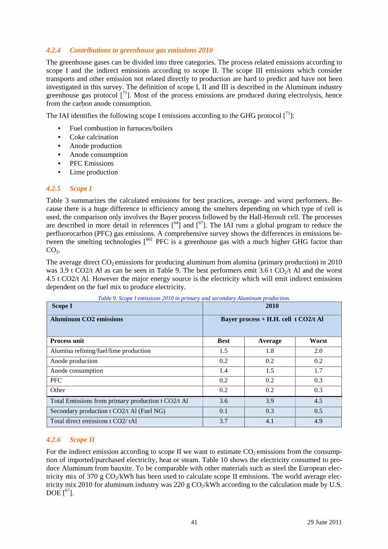
41 29 June 2011
4.2.4 Contributions to greenhouse gas emissions 2010
The greenhouse gases can be divided into three categories. The process related emissions according to scope I and the indirect emissions according to scope II. The scope III emissions which consider transports and other emission not related directly to production are hard to predict and have not been investigated in this survey. The definition of scope I, II and III is described in the Aluminum industry greenhouse gas protocol [71]. Most of the process emissions are produced during electrolysis, hence from the carbon anode consumption.
The IAI identifies the following scope I emissions according to the GHG protocol [71]:
• Fuel combustion in furnaces/boilers • Coke calcination • Anode production • Anode consumption • PFC Emissions • Lime production
4.2.5 Scope I
Table 3 summarizes the calculated emissions for best practices, average- and worst performers. Be-cause there is a huge difference in efficiency among the smelters depending on which type of cell is used, the comparison only involves the Bayer process followed by the Hall-Heroult cell. The processes are described in more detail in references [64] and [67]. The IAI runs a global program to reduce the perfluorocarbon (PFC) gas emissions. A comprehensive survey shows the differences in emissions be-tween the smelting technologies [66]. PFC is a greenhouse gas with a much higher GHG factor than CO2.
The average direct CO2 emissions for producing aluminum from alumina (primary production) in 2010 was 3.9 t CO2/t Al as can be seen in Table 9. The best performers emit 3.6 t CO2/t Al and the worst 4.5 t CO2/t Al. However the major energy source is the electricity which will emit indirect emissions dependent on the fuel mix to produce electricity.
Table 9. Scope I emissions 2010 in primary and secondary Aluminum production. Scope I 2010
Aluminum CO2 emissions Bayer process + H.H. cell t CO2/t Al
Process unit Best Average Worst
Alumina refining/fuel/lime production 1.5 1.8 2.0
Anode production 0.2 0.2 0.2
Anode consumption 1.4 1.5 1.7
PFC 0.2 0.2 0.3
Other 0.2 0.2 0.3
Total Emissions from primary production t CO2/t Al 3.6 3.9 4.5
Secondary production t CO2/t Al (Fuel NG) 0.1 0.3 0.5
Total direct emissions t CO2/ tAl 3.7 4.1 4.9
4.2.6 Scope II
For the indirect emission according to scope II we want to estimate CO2 emissions from the consump-tion of imported/purchased electricity, heat or steam. Table 10 shows the electricity consumed to pro-duce Aluminum from bauxite. To be comparable with other materials such as steel the European elec-tricity mix of 370 g CO2/kWh has been used to calculate scope II emissions. The world average elec-tricity mix 2010 for aluminum industry was 220 g CO2/kWh according to the calculation made by U.S. DOE [67].
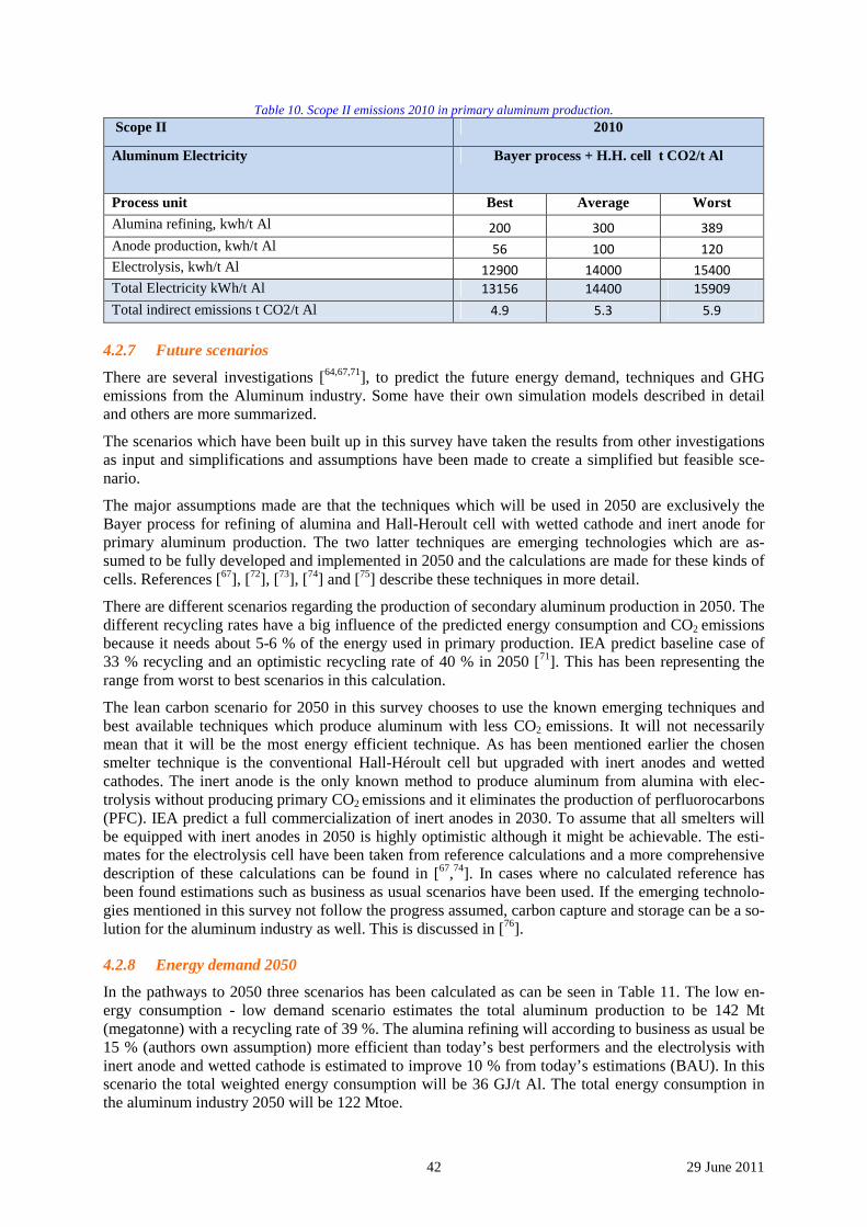
42 29 June 2011
Table 10. Scope II emissions 2010 in primary aluminum production. Scope II 2010
Aluminum Electricity Bayer process + H.H. cell t CO2/t Al
Process unit Best Average Worst
Alumina refining, kwh/t Al 200 300 389
Anode production, kwh/t Al 56 100 120
Electrolysis, kwh/t Al 12900 14000 15400
Total Electricity kWh/t Al 13156 14400 15909
Total indirect emissions t CO2/t Al 4.9 5.3 5.9
4.2.7 Future scenarios
There are several investigations [64,67,71], to predict the future energy demand, techniques and GHG emissions from the Aluminum industry. Some have their own simulation models described in detail and others are more summarized.
The scenarios which have been built up in this survey have taken the results from other investigations as input and simplifications and assumptions have been made to create a simplified but feasible sce-nario.
The major assumptions made are that the techniques which will be used in 2050 are exclusively the Bayer process for refining of alumina and Hall-Heroult cell with wetted cathode and inert anode for primary aluminum production. The two latter techniques are emerging technologies which are as-sumed to be fully developed and implemented in 2050 and the calculations are made for these kinds of cells. References [67], [72], [73], [74] and [75] describe these techniques in more detail.
There are different scenarios regarding the production of secondary aluminum production in 2050. The different recycling rates have a big influence of the predicted energy consumption and CO2 emissions because it needs about 5-6 % of the energy used in primary production. IEA predict baseline case of 33 % recycling and an optimistic recycling rate of 40 % in 2050 [71]. This has been representing the range from worst to best scenarios in this calculation.
The lean carbon scenario for 2050 in this survey chooses to use the known emerging techniques and best available techniques which produce aluminum with less CO2 emissions. It will not necessarily mean that it will be the most energy efficient technique. As has been mentioned earlier the chosen smelter technique is the conventional Hall-Héroult cell but upgraded with inert anodes and wetted cathodes. The inert anode is the only known method to produce aluminum from alumina with elec-trolysis without producing primary CO2 emissions and it eliminates the production of perfluorocarbons (PFC). IEA predict a full commercialization of inert anodes in 2030. To assume that all smelters will be equipped with inert anodes in 2050 is highly optimistic although it might be achievable. The esti-mates for the electrolysis cell have been taken from reference calculations and a more comprehensive description of these calculations can be found in [67,74]. In cases where no calculated reference has been found estimations such as business as usual scenarios have been used. If the emerging technolo-gies mentioned in this survey not follow the progress assumed, carbon capture and storage can be a so-lution for the aluminum industry as well. This is discussed in [76].
4.2.8 Energy demand 2050
In the pathways to 2050 three scenarios has been calculated as can be seen in Table 11. The low en-ergy consumption - low demand scenario estimates the total aluminum production to be 142 Mt (megatonne) with a recycling rate of 39 %. The alumina refining will according to business as usual be 15 % (authors own assumption) more efficient than today’s best performers and the electrolysis with inert anode and wetted cathode is estimated to improve 10 % from today’s estimations (BAU). In this scenario the total weighted energy consumption will be 36 GJ/t Al. The total energy consumption in the aluminum industry 2050 will be 122 Mtoe.
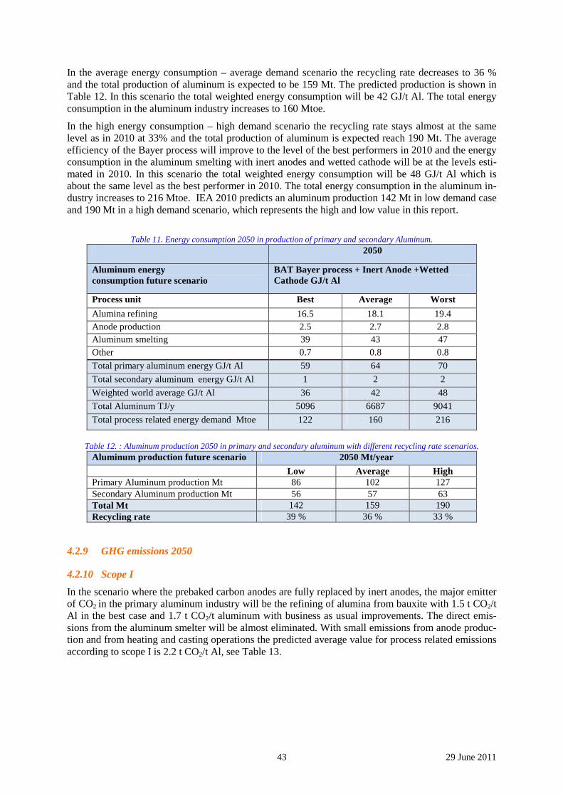
43 29 June 2011
In the average energy consumption – average demand scenario the recycling rate decreases to 36 % and the total production of aluminum is expected to be 159 Mt. The predicted production is shown in Table 12. In this scenario the total weighted energy consumption will be 42 GJ/t Al. The total energy consumption in the aluminum industry increases to 160 Mtoe.
In the high energy consumption – high demand scenario the recycling rate stays almost at the same level as in 2010 at 33% and the total production of aluminum is expected reach 190 Mt. The average efficiency of the Bayer process will improve to the level of the best performers in 2010 and the energy consumption in the aluminum smelting with inert anodes and wetted cathode will be at the levels esti-mated in 2010. In this scenario the total weighted energy consumption will be 48 GJ/t Al which is about the same level as the best performer in 2010. The total energy consumption in the aluminum in-dustry increases to 216 Mtoe. IEA 2010 predicts an aluminum production 142 Mt in low demand case and 190 Mt in a high demand scenario, which represents the high and low value in this report.
Table 11. Energy consumption 2050 in production of primary and secondary Aluminum.
2050
Aluminum energy consumption future scenario
BAT Bayer process + Inert Anode +Wetted Cathode GJ/t Al
Process unit Best Average Worst
Alumina refining 16.5 18.1 19.4 Anode production 2.5 2.7 2.8 Aluminum smelting 39 43 47 Other 0.7 0.8 0.8
Total primary aluminum energy GJ/t Al 59 64 70
Total secondary aluminum energy GJ/t Al 1 2 2
Weighted world average GJ/t Al 36 42 48
Total Aluminum TJ/y 5096 6687 9041
Total process related energy demand Mtoe 122 160 216
Table 12. : Aluminum production 2050 in primary and secondary aluminum with different recycling rate scenarios.
Aluminum production future scenario 2050 Mt/year
Low Average High Primary Aluminum production Mt 86 102 127 Secondary Aluminum production Mt 56 57 63 Total Mt 142 159 190 Recycling rate 39 % 36 % 33 %
4.2.9 GHG emissions 2050
4.2.10 Scope I
In the scenario where the prebaked carbon anodes are fully replaced by inert anodes, the major emitter of CO2 in the primary aluminum industry will be the refining of alumina from bauxite with 1.5 t CO2/t Al in the best case and 1.7 t CO2/t aluminum with business as usual improvements. The direct emis-sions from the aluminum smelter will be almost eliminated. With small emissions from anode produc-tion and from heating and casting operations the predicted average value for process related emissions according to scope I is 2.2 t CO2/t Al, see Table 13.
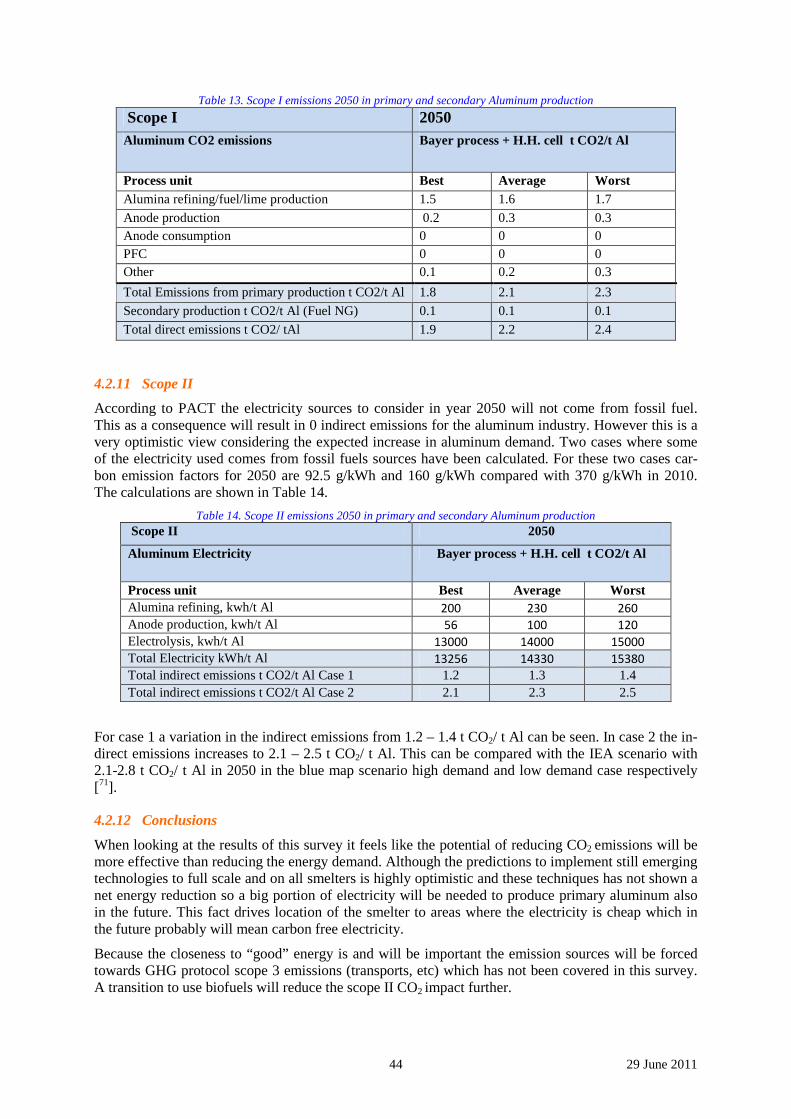
44 29 June 2011
Table 13. Scope I emissions 2050 in primary and secondary Aluminum production
Scope I 2050 Aluminum CO2 emissions Bayer process + H.H. cell t CO2/t Al
Process unit Best Average Worst Alumina refining/fuel/lime production 1.5 1.6 1.7
Anode production 0.2 0.3 0.3 Anode consumption 0 0 0 PFC 0 0 0 Other 0.1 0.2 0.3
Total Emissions from primary production t CO2/t Al 1.8 2.1 2.3
Secondary production t CO2/t Al (Fuel NG) 0.1 0.1 0.1
Total direct emissions t CO2/ tAl 1.9 2.2 2.4
4.2.11 Scope II
According to PACT the electricity sources to consider in year 2050 will not come from fossil fuel. This as a consequence will result in 0 indirect emissions for the aluminum industry. However this is a very optimistic view considering the expected increase in aluminum demand. Two cases where some of the electricity used comes from fossil fuels sources have been calculated. For these two cases car-bon emission factors for 2050 are 92.5 g/kWh and 160 g/kWh compared with 370 g/kWh in 2010. The calculations are shown in Table 14.
Table 14. Scope II emissions 2050 in primary and secondary Aluminum production Scope II 2050
Aluminum Electricity Bayer process + H.H. cell t CO2/t Al
Process unit Best Average Worst Alumina refining, kwh/t Al 200 230 260
Anode production, kwh/t Al 56 100 120
Electrolysis, kwh/t Al 13000 14000 15000
Total Electricity kWh/t Al 13256 14330 15380 Total indirect emissions t CO2/t Al Case 1 1.2 1.3 1.4 Total indirect emissions t CO2/t Al Case 2 2.1 2.3 2.5
For case 1 a variation in the indirect emissions from 1.2 – 1.4 t CO2/ t Al can be seen. In case 2 the in-direct emissions increases to 2.1 – 2.5 t CO2/ t Al. This can be compared with the IEA scenario with 2.1-2.8 t CO2/ t Al in 2050 in the blue map scenario high demand and low demand case respectively [71].
4.2.12 Conclusions
When looking at the results of this survey it feels like the potential of reducing CO2 emissions will be more effective than reducing the energy demand. Although the predictions to implement still emerging technologies to full scale and on all smelters is highly optimistic and these techniques has not shown a net energy reduction so a big portion of electricity will be needed to produce primary aluminum also in the future. This fact drives location of the smelter to areas where the electricity is cheap which in the future probably will mean carbon free electricity.
Because the closeness to “good” energy is and will be important the emission sources will be forced towards GHG protocol scope 3 emissions (transports, etc) which has not been covered in this survey. A transition to use biofuels will reduce the scope II CO2 impact further.
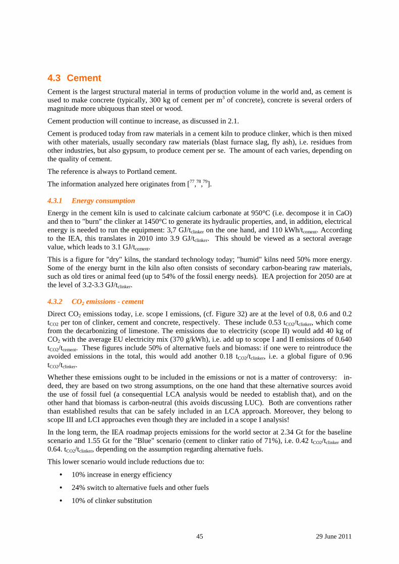
45 29 June 2011
4.3 Cement Cement is the largest structural material in terms of production volume in the world and, as cement is used to make concrete (typically, 300 kg of cement per m3 of concrete), concrete is several orders of magnitude more ubiquous than steel or wood.
Cement production will continue to increase, as discussed in 2.1.
Cement is produced today from raw materials in a cement kiln to produce clinker, which is then mixed with other materials, usually secondary raw materials (blast furnace slag, fly ash), i.e. residues from other industries, but also gypsum, to produce cement per se. The amount of each varies, depending on the quality of cement.
The reference is always to Portland cement.
The information analyzed here originates from [77,78,79].
4.3.1 Energy consumption
Energy in the cement kiln is used to calcinate calcium carbonate at 950°C (i.e. decompose it in CaO) and then to "burn" the clinker at 1450°C to generate its hydraulic properties, and, in addition, electrical energy is needed to run the equipment: 3,7 GJ/tclinker on the one hand, and 110 kWh/tcement. According to the IEA, this translates in 2010 into 3.9 GJ/tclinker. This should be viewed as a sectoral average value, which leads to 3.1 GJ/tcement.
This is a figure for "dry" kilns, the standard technology today; "humid" kilns need 50% more energy. Some of the energy burnt in the kiln also often consists of secondary carbon-bearing raw materials, such as old tires or animal feed (up to 54% of the fossil energy needs). IEA projection for 2050 are at the level of 3.2-3.3 GJ/tclinker.
4.3.2 CO2 emissions - cement
Direct CO2 emissions today, i.e. scope I emissions, (cf. Figure 32) are at the level of 0.8, 0.6 and 0.2 tCO2 per ton of clinker, cement and concrete, respectively. These include 0.53 tCO2/tclinker, which come from the decarbonizing of limestone. The emissions due to electricity (scope II) would add 40 kg of CO2 with the average EU electricity mix (370 g/kWh), i.e. add up to scope I and II emissions of 0.640 tCO2/tcement. These figures include 50% of alternative fuels and biomass: if one were to reintroduce the avoided emissions in the total, this would add another 0.18 tCO2/tclinker, i.e. a global figure of 0.96 tCO2/tclinker.
Whether these emissions ought to be included in the emissions or not is a matter of controversy: in-deed, they are based on two strong assumptions, on the one hand that these alternative sources avoid the use of fossil fuel (a consequential LCA analysis would be needed to establish that), and on the other hand that biomass is carbon-neutral (this avoids discussing LUC). Both are conventions rather than established results that can be safely included in an LCA approach. Moreover, they belong to scope III and LCI approaches even though they are included in a scope I analysis!
In the long term, the IEA roadmap projects emissions for the world sector at 2.34 Gt for the baseline scenario and 1.55 Gt for the "Blue" scenario (cement to clinker ratio of 71%), i.e. 0.42 tCO2/tclinker and 0.64. tCO2/tclinker, depending on the assumption regarding alternative fuels.
This lower scenario would include reductions due to:
• 10% increase in energy efficiency
• 24% switch to alternative fuels and other fuels
• 10% of clinker substitution
46 29 June 2011
• 56% due to CCS implementation, i.e. 220 to 430 kilns equipped by 2050.
Seen from the eyes of an expert from a different sector, there are a lot of ad hoc assumptions in this scenario, related mainly to the effect of clinker and fuel substitution. One of them, for instance, is that blast furnace slag is sold to the cement industry without any CO2 allocation, which the Steel sector is not necessarily willing to do.
Figure 32 – scheme of cement production and pie chart of CO2 emissions categories
On the other hand, the roadmap projections do not include some possible breakthrough products for the cement sector, which would decrease CO2 emissions dramatically, such as:
• NOVACEM cement, made from MgO (ex silicates) rather than CaO (ex carbonates)-based ce-ment, would reduce significantly CO2 needs and the product would harden by picking up CO2 from the atmosphere, thus opening up the prospect that this cement would be carbon-negative [80].
• CALERA proposes to mix calcium and magnesium carbonates and hydroxides, to add brine, sea water or brackish water and to use the waste heat from a power station's flue gas and its CO2 content to precipitate carbonates and decrease overall carbon footprint compared to Port-land cement [81].
• CALIX's cement is produced by calcinizing dolomite rocks in superheated steam, the resulting CO2 being highly concentrated and easier to capture and further store [82].
• Geopolymer cements use residues from other industries, concrete waste and activates the hy-draulic properties using alkalis (NaOH or KOH) [83].
The potential of these solutions to cut emissions is real but the market share that they can grab by 2050 is very uncertain.
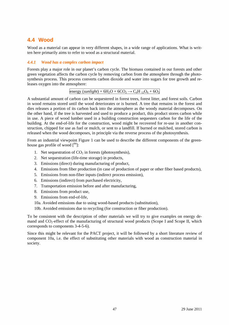
47 29 June 2011
4.4 Wood Wood as a material can appear in very different shapes, in a wide range of applications. What is writ-ten here primarily aims to refer to wood as a structural material.
4.4.1 Wood has a complex carbon impact
Forests play a major role in our planet’s carbon cycle. The biomass contained in our forests and other green vegetation affects the carbon cycle by removing carbon from the atmosphere through the photo-synthesis process. This process converts carbon dioxide and water into sugars for tree growth and re-leases oxygen into the atmosphere:
energy (sunlight) + 6H2O + 6CO2 → C6H 12O6 + 6O2
A substantial amount of carbon can be sequestered in forest trees, forest litter, and forest soils. Carbon in wood remains stored until the wood deteriorates or is burned. A tree that remains in the forest and dies releases a portion of its carbon back into the atmosphere as the woody material decomposes. On the other hand, if the tree is harvested and used to produce a product, this product stores carbon while in use. A piece of wood lumber used in a building construction sequesters carbon for the life of the building. At the end-of-life for the construction, wood might be recovered for re-use in another con-struction, chipped for use as fuel or mulch, or sent to a landfill. If burned or mulched, stored carbon is released when the wood decomposes, in principle via the reverse process of the photosynthesis.
From an industrial viewpoint Figure 1 can be used to describe the different components of the green-house gas profile of wood [84]:
1. Net sequestration of CO2 in forests (photosynthesis), 2. Net sequestration (life-time storage) in products, 3. Emissions (direct) during manufacturing of product, 4. Emissions from fiber production (in case of production of paper or other fiber based products), 5. Emissions from non-fiber inputs (indirect process emission), 6. Emissions (indirect) from purchased electricity, 7. Transportation emission before and after manufacturing, 8. Emissions from product use, 9. Emissions from end-of-life, 10a. Avoided emissions due to using wood-based products (substitution), 10b. Avoided emissions due to recycling (for construction or fiber production).
To be consistent with the description of other materials we will try to give examples on energy de-mand and CO2-effect of the manufacturing of structural wood products (Scope I and Scope II, which corresponds to components 3-4-5-6).
Since this might be relevant for the PACT project, it will be followed by a short literature review of component 10a, i.e. the effect of substituting other materials with wood as construction material in society.
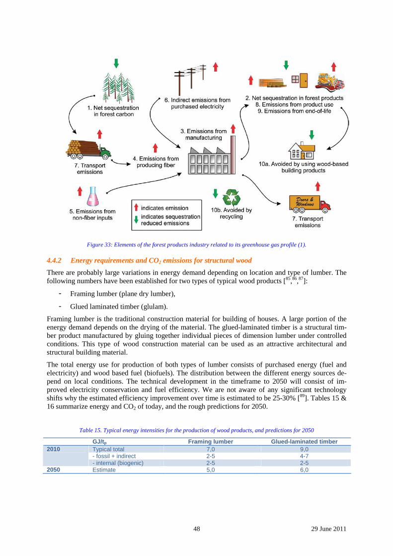
48 29 June 2011
Figure 33: Elements of the forest products industry related to its greenhouse gas profile (1).
4.4.2 Energy requirements and CO2 emissions for structural wood
There are probably large variations in energy demand depending on location and type of lumber. The following numbers have been established for two types of typical wood products [85,86,87]:
- Framing lumber (plane dry lumber),
- Glued laminated timber (glulam).
Framing lumber is the traditional construction material for building of houses. A large portion of the energy demand depends on the drying of the material. The glued-laminated timber is a structural tim-ber product manufactured by gluing together individual pieces of dimension lumber under controlled conditions. This type of wood construction material can be used as an attractive architectural and structural building material.
The total energy use for production of both types of lumber consists of purchased energy (fuel and electricity) and wood based fuel (biofuels). The distribution between the different energy sources de-pend on local conditions. The technical development in the timeframe to 2050 will consist of im-proved electricity conservation and fuel efficiency. We are not aware of any significant technology shifts why the estimated efficiency improvement over time is estimated to be 25-30% [89]. Tables 15 & 16 summarize energy and CO2 of today, and the rough predictions for 2050.
Table 15. Typical energy intensities for the production of wood products, and predictions for 2050
GJ/tp Framing lumber Glued-laminated timber Typical total 7,0 9,0 - fossil + indirect 2-5 4-7
2010
- internal (biogenic) 2-5 2-5 2050 Estimate 5,0 6,0
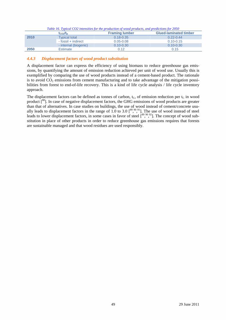
49 29 June 2011
Table 16. Typical CO2 intensities for the production of wood products, and predictions for 2050 tCO2/tp Framing lumber Glued-laminated timber
Typical total 0.18-0.35 0.22-0.44 - fossil + indirect 0.05-0.08 0.10-0.15
2010
- internal (biogenic) 0.10-0.30 0.10-0.30 2050 Estimate 0.12 0.15
4.4.3 Displacement factors of wood product substitution
A displacement factor can express the efficiency of using biomass to reduce greenhouse gas emis-sions, by quantifying the amount of emission reduction achieved per unit of wood use. Usually this is exemplified by comparing the use of wood products instead of a cement-based product. The rationale is to avoid CO2 emissions from cement manufacturing and to take advantage of the mitigation possi-bilities from forest to end-of-life recovery. This is a kind of life cycle analysis / life cycle inventory approach.
The displacement factors can be defined as tonnes of carbon, tC, of emission reduction per tC in wood product [88]. In case of negative displacement factors, the GHG emissions of wood products are greater than that of alternatives. In case studies on buildings, the use of wood instead of cement/concrete usu-ally leads to displacement factors in the range of 1.0 to 3.0 [89,90,91]. The use of wood instead of steel leads to lower displacement factors, in some cases in favor of steel [89,90,92]. The concept of wood sub-stitution in place of other products in order to reduce greenhouse gas emissions requires that forests are sustainable managed and that wood residues are used responsibly.
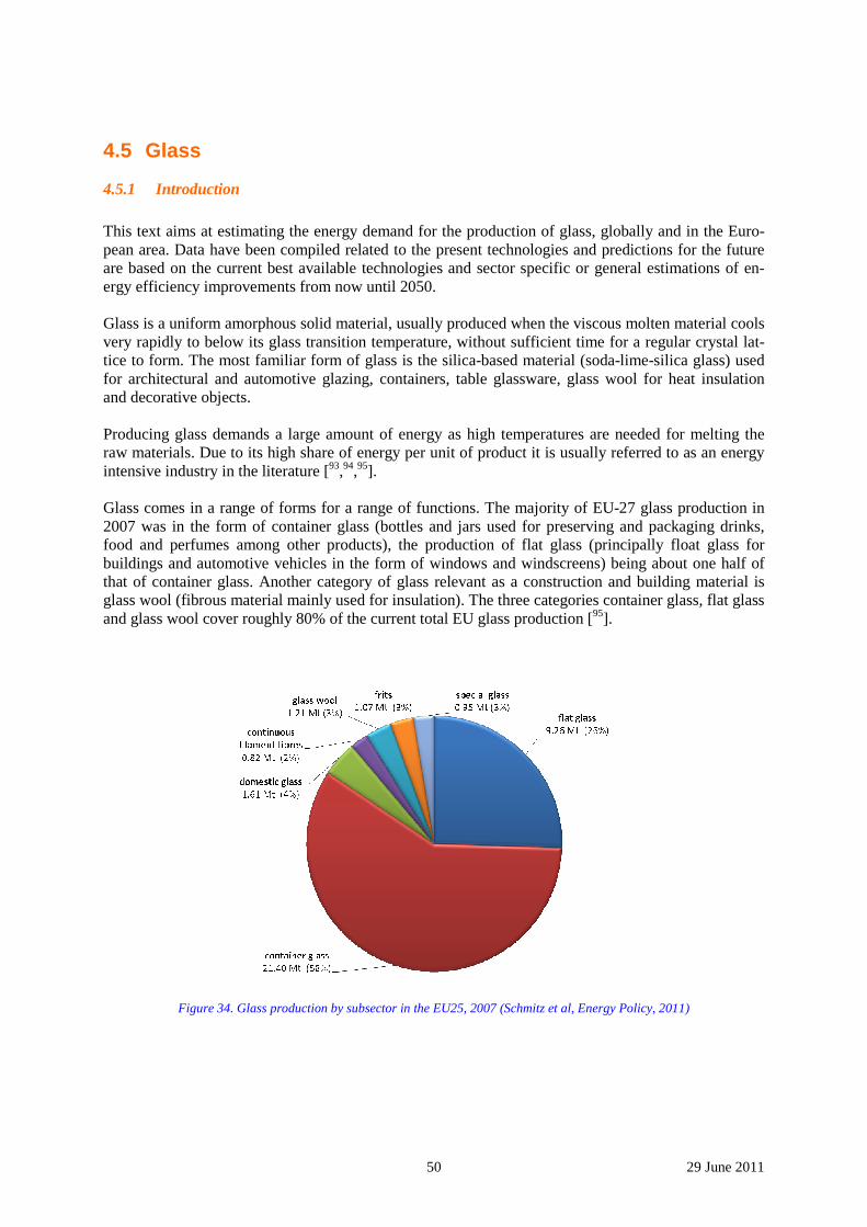
50 29 June 2011
4.5 Glass
4.5.1 Introduction
This text aims at estimating the energy demand for the production of glass, globally and in the Euro-pean area. Data have been compiled related to the present technologies and predictions for the future are based on the current best available technologies and sector specific or general estimations of en-ergy efficiency improvements from now until 2050. Glass is a uniform amorphous solid material, usually produced when the viscous molten material cools very rapidly to below its glass transition temperature, without sufficient time for a regular crystal lat-tice to form. The most familiar form of glass is the silica-based material (soda-lime-silica glass) used for architectural and automotive glazing, containers, table glassware, glass wool for heat insulation and decorative objects. Producing glass demands a large amount of energy as high temperatures are needed for melting the raw materials. Due to its high share of energy per unit of product it is usually referred to as an energy intensive industry in the literature [93,94,95]. Glass comes in a range of forms for a range of functions. The majority of EU-27 glass production in 2007 was in the form of container glass (bottles and jars used for preserving and packaging drinks, food and perfumes among other products), the production of flat glass (principally float glass for buildings and automotive vehicles in the form of windows and windscreens) being about one half of that of container glass. Another category of glass relevant as a construction and building material is glass wool (fibrous material mainly used for insulation). The three categories container glass, flat glass and glass wool cover roughly 80% of the current total EU glass production [95].
Figure 34. Glass production by subsector in the EU25, 2007 (Schmitz et al, Energy Policy, 2011)
51 29 June 2011
4.5.2 GLASS production
Manufacturing processes
Production of glass involves five main procedures:
• batch preparation / mixing, • melting, • forming, • annealing, and • finishing.
The two principle kinds of mixing are wet mixing and batch agglomeration. Glass with large silicon dioxide content is wet mixed. Glasses with high lead oxide are mixed by batch agglomeration.
The type of melting unit employed depends on the quantity and quality of glass to be processed. For small production and special glass, melting is performed in pot furnaces or crucibles. In large facto-ries, a dozen or so pot furnaces may be heated by one central furnace. Larger batches are melted in large covered furnaces or tanks to which heat is supplied by a flame. For high quality glass, small con-tinuous melting tanks are used to process low volumes of material. Large quantities of high quality glass are melted in continuous regenerative furnaces that recover waste heat from burned gases. Flat glass furnaces provide a larger amount of quality glass and are longer than furnaces used by glass con-tainer manufacturers. Although glass tanks are fired by gas or oil, supplementary heating with electric-ity is commonly used.
After the glass has melted, the molten glass is taken from the tanks to the forming operation, which is different for each type of glass product. Once formed, all glass articles need to be slowly cooled or an-nealed, usually in a long oven called “lehr”. The purpose of annealing is to reduce the internal stresses which can crack the glass during cooling. Internal stresses are created because of temperature varia-tions throughout the piece; different parts of the glass become rigid at different times.
The two types of finishing processes are mechanical and chemical. Mechanical processes include cut-ting, drilling, grinding, and polishing. Chemical treatments are used to alter the strength, appearance, and durability of the product. Once finished, the glass products are cleaned using several agents, in-cluding aqueous solvents, organic solvents, and hydrocarbon or halocarbon solvents.
Product categories
Container glass
Container glass stands in contrast to flat glass (used for windows, glass doors, transparent walls, wind-shields) and fiberglass (used for thermal insulation, plastic reinforcement and optical communication). Most container glass is soda-lime glass, produced by blowing and pressing techniques, while some laboratory glassware is made from borosilicate glass. About 95% of the production is used for packag-ing of food and drinks. The special products for packaging of pharmaceuticals, perfumes and technical products are subject to a higher degree of processing compared to standard products. Recycled post-consumer glass is used in extensive volumes for production of container glass.
Flat glass
Flat glass is typically made by the float process. The raw materials used in this process include silica sand, soda ash, limestone, dolomite, cullet (pieces of broken glass), and small amounts of other mate-rials. These materials are proportioned to meet certain physical characteristics, mixed, and fed into the melting tank, where temperatures of about 1,600°C reduce the material to glass. Coloring agents may be added at this time to produce differing degrees of translucence. The molten glass is then fed as a continuous ribbon from the furnace into a bath of molten tin where it floats (glass is lighter than tin) and is fire polished. The ribbon of glass leaves the float bath and enters the annealing lehr where it is gradually cooled to prevent flaw-causing stresses. The glass is then cut. At this point, the glass may be packaged and sent to a customer, immediately subjected to further processing, or sent to storage for inventory or future processing.
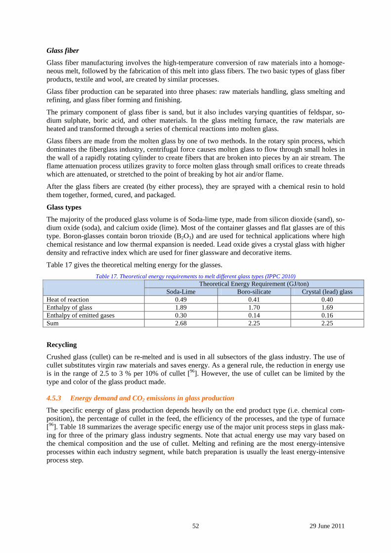
52 29 June 2011
Glass fiber
Glass fiber manufacturing involves the high-temperature conversion of raw materials into a homoge-neous melt, followed by the fabrication of this melt into glass fibers. The two basic types of glass fiber products, textile and wool, are created by similar processes.
Glass fiber production can be separated into three phases: raw materials handling, glass smelting and refining, and glass fiber forming and finishing.
The primary component of glass fiber is sand, but it also includes varying quantities of feldspar, so-dium sulphate, boric acid, and other materials. In the glass melting furnace, the raw materials are heated and transformed through a series of chemical reactions into molten glass.
Glass fibers are made from the molten glass by one of two methods. In the rotary spin process, which dominates the fiberglass industry, centrifugal force causes molten glass to flow through small holes in the wall of a rapidly rotating cylinder to create fibers that are broken into pieces by an air stream. The flame attenuation process utilizes gravity to force molten glass through small orifices to create threads which are attenuated, or stretched to the point of breaking by hot air and/or flame.
After the glass fibers are created (by either process), they are sprayed with a chemical resin to hold them together, formed, cured, and packaged.
Glass types
The majority of the produced glass volume is of Soda-lime type, made from silicon dioxide (sand), so-dium oxide (soda), and calcium oxide (lime). Most of the container glasses and flat glasses are of this type. Boron-glasses contain boron trioxide (B2O3) and are used for technical applications where high chemical resistance and low thermal expansion is needed. Lead oxide gives a crystal glass with higher density and refractive index which are used for finer glassware and decorative items.
Table 17 gives the theoretical melting energy for the glasses.
Table 17. Theoretical energy requirements to melt different glass types (IPPC 2010) Theoretical Energy Requirement (GJ/ton)
Soda-Lime Boro-silicate Crystal (lead) glass
Heat of reaction 0.49 0.41 0.40 Enthalpy of glass 1.89 1.70 1.69 Enthalpy of emitted gases 0.30 0.14 0.16 Sum 2.68 2.25 2.25
Recycling
Crushed glass (cullet) can be re-melted and is used in all subsectors of the glass industry. The use of cullet substitutes virgin raw materials and saves energy. As a general rule, the reduction in energy use is in the range of 2.5 to 3 % per 10% of cullet [96]. However, the use of cullet can be limited by the type and color of the glass product made.
4.5.3 Energy demand and CO2 emissions in glass production
The specific energy of glass production depends heavily on the end product type (i.e. chemical com-position), the percentage of cullet in the feed, the efficiency of the processes, and the type of furnace [96]. Table 18 summarizes the average specific energy use of the major unit process steps in glass mak-ing for three of the primary glass industry segments. Note that actual energy use may vary based on the chemical composition and the use of cullet. Melting and refining are the most energy-intensive processes within each industry segment, while batch preparation is usually the least energy-intensive process step.
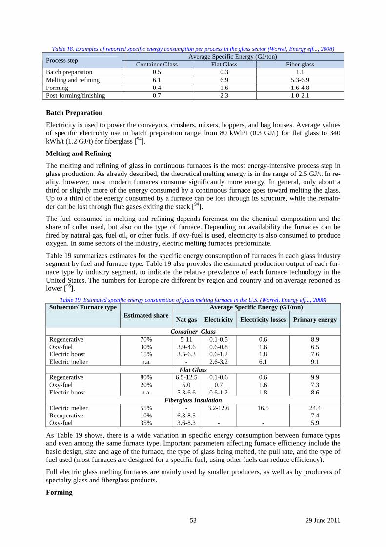
53 29 June 2011
Table 18. Examples of reported specific energy consumption per process in the glass sector (Worrel, Energy eff..., 2008) Average Specific Energy (GJ/ton)
Process step Container Glass Flat Glass Fiber glass
Batch preparation 0.5 0.3 1.1 Melting and refining 6.1 6.9 5.3-6.9 Forming 0.4 1.6 1.6-4.8 Post-forming/finishing 0.7 2.3 1.0-2.1 Batch Preparation
Electricity is used to power the conveyors, crushers, mixers, hoppers, and bag houses. Average values of specific electricity use in batch preparation range from 80 kWh/t (0.3 GJ/t) for flat glass to 340 kWh/t (1.2 GJ/t) for fiberglass [94].
Melting and Refining
The melting and refining of glass in continuous furnaces is the most energy-intensive process step in glass production. As already described, the theoretical melting energy is in the range of 2.5 GJ/t. In re-ality, however, most modern furnaces consume significantly more energy. In general, only about a third or slightly more of the energy consumed by a continuous furnace goes toward melting the glass. Up to a third of the energy consumed by a furnace can be lost through its structure, while the remain-der can be lost through flue gases exiting the stack [94].
The fuel consumed in melting and refining depends foremost on the chemical composition and the share of cullet used, but also on the type of furnace. Depending on availability the furnaces can be fired by natural gas, fuel oil, or other fuels. If oxy-fuel is used, electricity is also consumed to produce oxygen. In some sectors of the industry, electric melting furnaces predominate.
Table 19 summarizes estimates for the specific energy consumption of furnaces in each glass industry segment by fuel and furnace type. Table 19 also provides the estimated production output of each fur-nace type by industry segment, to indicate the relative prevalence of each furnace technology in the United States. The numbers for Europe are different by region and country and on average reported as lower [95].
Table 19. Estimated specific energy consumption of glass melting furnace in the U.S. (Worrel, Energy eff..., 2008) Average Specific Energy (GJ/ton) Subsector/ Furnace type
Estimated share
Nat gas Electricity Electricity losses Primary energy
Container Glass Regenerative 70% 5-11 0.1-0.5 0.6 8.9 Oxy-fuel 30% 3.9-4.6 0.6-0.8 1.6 6.5 Electric boost 15% 3.5-6.3 0.6-1.2 1.8 7.6 Electric melter n.a. - 2.6-3.2 6.1 9.1
Flat Glass Regenerative 80% 6.5-12.5 0.1-0.6 0.6 9.9 Oxy-fuel 20% 5.0 0.7 1.6 7.3 Electric boost n.a. 5.3-6.6 0.6-1.2 1.8 8.6
Fiberglass Insulation Electric melter 55% - 3.2-12.6 16.5 24.4 Recuperative 10% 6.3-8.5 - - 7.4 Oxy-fuel 35% 3.6-8.3 - - 5.9
As Table 19 shows, there is a wide variation in specific energy consumption between furnace types and even among the same furnace type. Important parameters affecting furnace efficiency include the basic design, size and age of the furnace, the type of glass being melted, the pull rate, and the type of fuel used (most furnaces are designed for a specific fuel; using other fuels can reduce efficiency).
Full electric glass melting furnaces are mainly used by smaller producers, as well as by producers of specialty glass and fiberglass products.
Forming
54 29 June 2011
After glass is melted and refined in the furnace, molten glass is passed into the fore hearth where it is conditioned to a temperature suitable for forming. The molten glass is then formed using any number of different processes, which depend on the desired shape of the final product. Natural gas and elec-tricity are the main forms of energy used in forming. Most of the electricity is used to drive forming machines, fans, blowers, compressors, and conveyors. In forming processes where proper working temperatures need to be maintained, fuels and electricity are used to control the process heat.
The energy used in forming is highly product dependent; energy use in forming can account for any-where from 12% (for flat glass) to 34% (for fiber forming) of the total primary energy consumed in glass production. In flat glass production, electricity is used to maintain the molten state of the tin bath and to drive rollers. In the production of glass containers, final form is obtained using either com-pressed air (blow and blow method) or a combination of compressed air and electricity-driven me-chanical pressing (press and blow method). The primary forming processes used in specialty glass production - press and blow, press-forming, lamp-forming, spinning, and drawing - are also electric-ity-driven. In the production of glass wool, both electricity (for rotary spinners and conveyors) and fu-els (for steam blowing or flame attenuation) can be consumed. Estimates for the average specific en-ergy use of forming processes in each glass industry segment are 1.2-2.5 GJ/t for container glass, about 5 GJ/t for flat glass, and in the broader span of 6-18 GJ/t for fibre/wool [94,95].
Post-Forming and Finishing
After being formed into its final shape, a glass product may be subjected to several different post-forming and finishing processes, including curing/drying, annealing, bending, tempering, laminating, coating, cutting, drilling, and polishing.
Annealing is performed on all glass products except fibers and thin-walled products, such as light bulbs. Annealing takes place in a lehr (electric or fossil fuel fired), where the rate of glass cooling is carefully controlled to remove internal stresses. Many annealing lehrs are fired with natural gas. An-nealing process typically consume 25% of the total final energy in a glass plant.
After annealing, some flat glass is subjected to tempering to improve its strength. Tempering can oc-cur in either an electric or natural gas-fired furnace. Automotive flat glass typically undergoes me-chanical bending prior to tempering to attain desired curvature.
Coatings are applied to glass containers after the annealing process to improve scratch resistance.
Glass wool fibers are subjected to a curing and drying process after forming. [94,95].
Environmental issues
The combustion-based melting process inevitably pollutes the air with NOx, SOx and particulates; emissions of VOC, heavy metals, crystalline silica, fine particulate and greenhouse gas emissions are concerns as well. Ever-expanding environmental regulations force the glass industry to find alterna-tive, cost-effective melting technologies that maximize energy usage and reduce atmospheric emis-sions. Advances in glass melting technology must be developed for environmental compliance, fur-nace durability and cost effective production. Combustion regenerative and recuperative-heated fur-naces must be replaced, modified or equipped to comply with clean air laws. Techniques to recycle glass industry wastes and used glass products must be developed. Melting tanks could be replaced with smaller, less expensive and more flexible melting technologies [97].
Direct CO2 emissions result from process emissions as well as from fossil fuel combustion.
Process emissions occur due to the decarbonisation of the carbonate raw material in the process input, mainly sodium carbonate Na2CO3, limestone CaCO3 and dolomite CaMg(CO3)2.
4.5.4 Energy requirement and CO2 emission
Data have been derived from literature. The sources are:
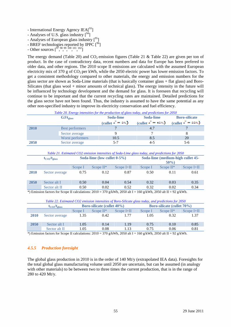
55 29 June 2011
- International Energy Agency IEA[93] - Analyses of U.S. glass industry [94] - Analyses of European glass industry [95] - BREF technologies reported by IPPC [96] - Other sources [97,98,99,100,101,102]
The energy demand (Table 20) and CO2 emission figures (Table 21 & Table 22) are given per ton of product. In the case of contradictory data, recent numbers and data for Europe has been prefered to older data, and other regions. The 2010 scope II emissions are calculated with the assumed European electricity mix of 370 g of CO2 per kWh, while the 2050 electric power has lower emission factors. To get a consistent methodology compared to other materials, the energy and emission numbers for the glass sector are shown as Soda-Lime materials (that is basically container glass + flat glass) and Boro-Silicates (that glass wool + minor amounts of technical glass). The energy intensity in the future will be influenced by technology development and the demand for glass. It is foreseen that recycling will continue to be important and that the current recycling rates are maintained. Detailed predictions for the glass sector have not been found. Thus, the industry is assumed to have the same potential as any other non-specified industry to improve its electricity conservation and fuel efficiency.
Table 20. Energy intensities for the production of glass today, and predictions for 2050 GJ/tglass Soda-lime
(cullet
Soda-lime
(cullet
Boro-silicate
(cullet Best performers 7 4.7 7 Sector average 9 7 8
2010
Worst performers 10.5 8.5 20 2050 Sector average 5-7 4-5 5-6
Table 21. Estimated CO2 emission intensities of Soda-Lime glass today, and predictions for 2050
tCO2/tglass Soda-lime (low cullet 0-5%) Soda-lime (medium-high cullet 45-50%)
Scope I Scope II* Scope I+II Scope I Scope II* Scope I+II 2010 Sector average 0.75
0.12 0.87 0.50 0.11 0.61
Sector alt I 0.50 0.04 0.54 0.32 0.03 0.35 2050 Sector alt II 0.50 0.02 0.52 0.32 0.02 0.34
*) Emission factors for Scope II calculations: 2010 = 370 g/kWh, 2050 alt I = 160 g/kWh, 2050 alt II = 92 g/kWh.
Table 22. Estimated CO2 emission intensities of Boro-Silicate glass today, and predictions for 2050
tCO2/tglass Boro-silicate (cullet 40%) Boro-silicate (cullet 70%) Scope I Scope II* Scope I+II Scope I Scope II* Scope I+II
2010 Sector average 1.35
0.42 1.77 1.05 0.32 1.37
Sector alt I 1.05 0.14 1.19 0.75 0.10 0.85 2050 Sector alt II 1.05 0.08 1.13 0.75 0.06 0.81
*) Emission factors for Scope II calculations: 2010 = 370 g/kWh, 2050 alt I = 160 g/kWh, 2050 alt II = 92 g/kWh.
4.5.5 Production foresight
The global glass production in 2010 is in the order of 140 Mt/y (extrapolated IEA data). Foresights for the total global glass manufacturing volume until 2050 are uncertain, but can be assumed (in analogy with other materials) to be between two to three times the current production, that is in the range of 280 to 420 Mt/y.
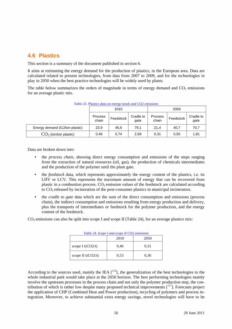
56 29 June 2011
4.6 Plastics This section is a summary of the document published in section 6.
It aims at estimating the energy demand for the production of plastics, in the European area. Data are calculated related to present technologies, from data from 2007 to 2009, and for the technologies in play in 2050 when the best practice technologies will be widely used by plants.
The table below summarizes the orders of magnitude in terms of energy demand and CO2 emissions for an average plastic mix.
Table 23. Plastics data on energy needs and CO2 emissions
2010 2050
Process chain Feedstock Cradle to
gate Process
chain Feedstock Cradle to gate
Energy demand (GJ/ton plastic) 23,9 45,6 79,1 21,4 40,7 70,7
CO2 (ton/ton plastic) 0,46 0,74 2,69 0,31 0,50 1,81
Data are broken down into:
• the process chain, showing direct energy consumption and emissions of the steps ranging from the extraction of natural resources (oil, gas), the production of chemicals intermediates and the production of the polymer until the plant gate.
• the feedstock data, which represents approximately the energy content of the plastics, i.e. its LHV or LCV. This represents the maximum amount of energy that can be recovered from plastic in a combustion process. CO2 emission values of the feedstock are calculated according to CO2 released by incineration of the post-consumer plastics in municipal incinerators.
• the cradle to gate data which are the sum of the direct consumption and emissions (process chain), the indirect consumption and emissions resulting from energy production and delivery, plus the transports of intermediates or feedstock for the polymer production, and the energy content of the feedstock.
CO2 emissions can also be split into scope I and scope II (Table 24), for an average plastics mix:
Table 24. Scope I and scope II CO2 emissions 2010 2050
scope I (tCO2/t) 0,46 0,31
scope II (tCO2/t) 0,53 0,36
According to the sources used, mainly the IEA [115], the generalization of the best technologies to the whole industrial park would take place at the 2050 horizon. The best performing technologies mainly involve the upstream processes in the process chain and not only the polymer production step, the con-tribution of which is rather low despite many proposed technical improvements [117]. Forecasts project the application of CHP (Combined Heat and Power production), recycling of polymers and process in-tegration. Moreover, to achieve substantial extra energy savings, novel technologies will have to be

57 29 June 2011
implemented such as in the production of olefins (polyethylene and polypropylene based plastics), like a greater use of catalysis and new chemicals separation processes. Bio-based chemicals are an impor-tant option that should lower CO2 emissions. Others savings should also be due to fuel switching, bet-ter energy efficiency and reduction of direct fuel use.
As far as CO2 emissions are concerned, it is a very challenging matter for the plastic industry to reduce them due to the high share of feedstock content: here, the way for improvement goes through increas-ing the recycling rate of plastics and the use of biomass feedstocks.
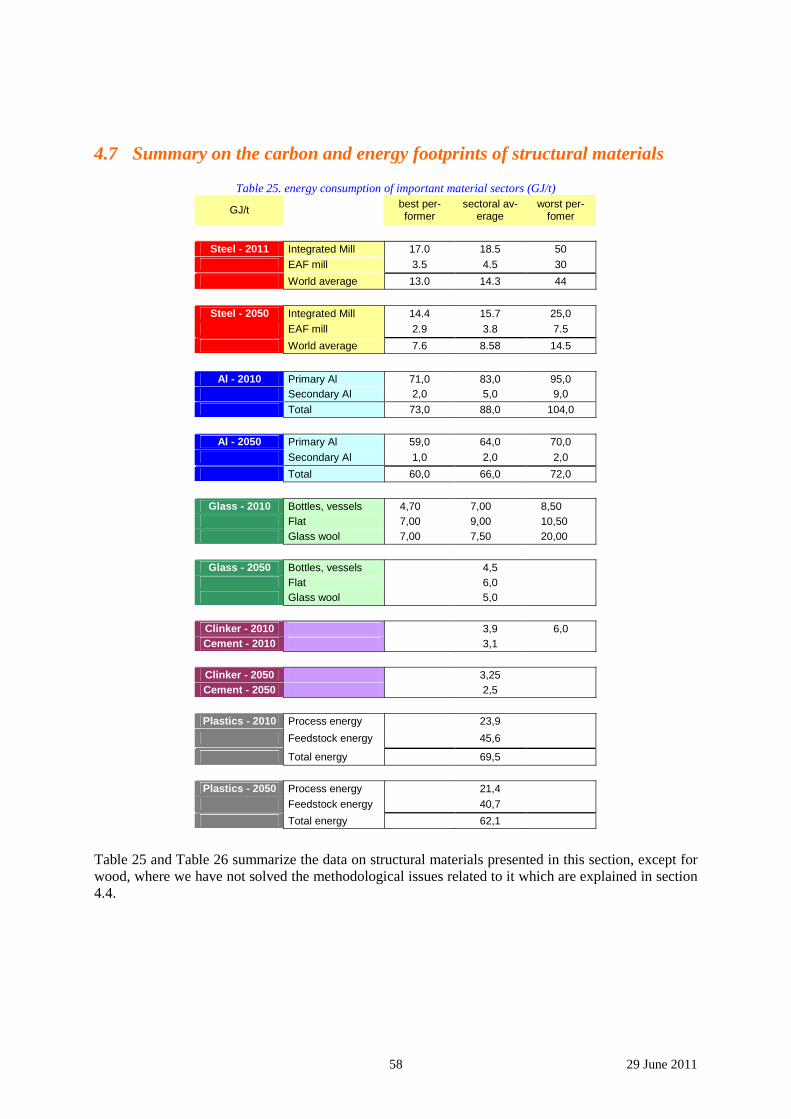
58 29 June 2011
4.7 Summary on the carbon and energy footprints of structural materials
Table 25. energy consumption of important material sectors (GJ/t)
GJ/t best per-former
sectoral av-erage
worst per-fomer
Steel - 2011 Integrated Mill 17.0 18.5 50 EAF mill 3.5 4.5 30
World average 13.0 14.3 44
Steel - 2050 Integrated Mill 14.4 15.7 25,0 EAF mill 2.9 3.8 7.5
World average 7.6 8.58 14.5
Al - 2010 Primary Al 71,0 83,0 95,0 Secondary Al 2,0 5,0 9,0
Total 73,0 88,0 104,0
Al - 2050 Primary Al 59,0 64,0 70,0 Secondary Al 1,0 2,0 2,0
Total 60,0 66,0 72,0
Glass - 2010 Bottles, vessels 4,70 7,00 8,50 Flat 7,00 9,00 10,50 Glass wool 7,00 7,50 20,00
Glass - 2050 Bottles, vessels 4,5 Flat 6,0 Glass wool 5,0
Clinker - 2010 3,9 6,0 Cement - 2010 3,1
Clinker - 2050 3,25 Cement - 2050 2,5
Plastics - 2010 Process energy 23,9
Feedstock energy 45,6
Total energy 69,5
Plastics - 2050 Process energy 21,4 Feedstock energy 40,7
Total energy 62,1
Table 25 and Table 26 summarize the data on structural materials presented in this section, except for wood, where we have not solved the methodological issues related to it which are explained in section 4.4.
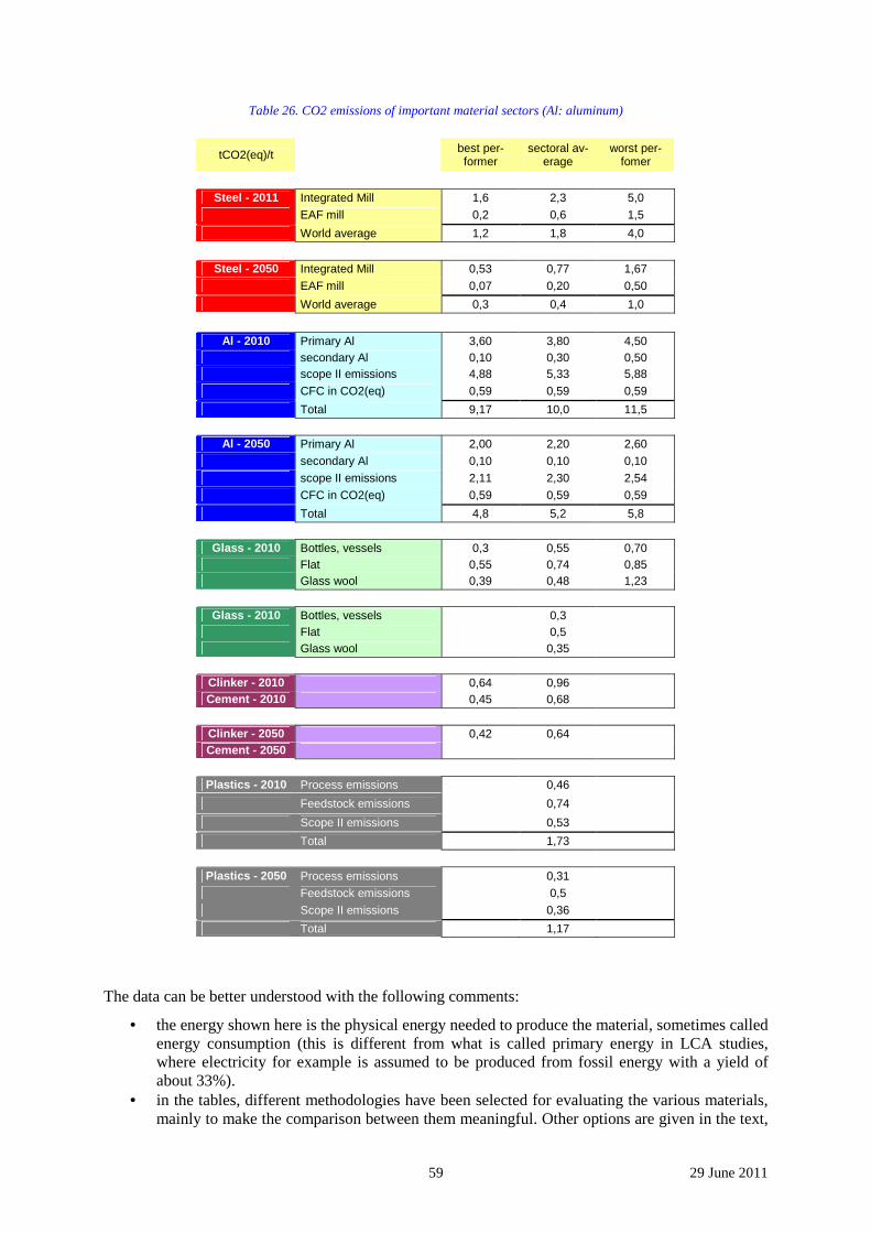
59 29 June 2011
Table 26. CO2 emissions of important material sectors (Al: aluminum)
tCO2(eq)/t best per-former
sectoral av-erage
worst per-fomer
Steel - 2011 Integrated Mill 1,6 2,3 5,0 EAF mill 0,2 0,6 1,5
World average 1,2 1,8 4,0
Steel - 2050 Integrated Mill 0,53 0,77 1,67 EAF mill 0,07 0,20 0,50
World average 0,3 0,4 1,0
Al - 2010 Primary Al 3,60 3,80 4,50 secondary Al 0,10 0,30 0,50 scope II emissions 4,88 5,33 5,88 CFC in CO2(eq) 0,59 0,59 0,59
Total 9,17 10,0 11,5
Al - 2050 Primary Al 2,00 2,20 2,60 secondary Al 0,10 0,10 0,10 scope II emissions 2,11 2,30 2,54 CFC in CO2(eq) 0,59 0,59 0,59
Total 4,8 5,2 5,8
Glass - 2010 Bottles, vessels 0,3 0,55 0,70 Flat 0,55 0,74 0,85 Glass wool 0,39 0,48 1,23
Glass - 2010 Bottles, vessels 0,3 Flat 0,5 Glass wool 0,35
Clinker - 2010 0,64 0,96 Cement - 2010 0,45 0,68
Clinker - 2050 0,42 0,64 Cement - 2050
Plastics - 2010 Process emissions 0,46
Feedstock emissions 0,74
Scope II emissions 0,53
Total 1,73
Plastics - 2050 Process emissions 0,31 Feedstock emissions 0,5 Scope II emissions 0,36
Total 1,17
The data can be better understood with the following comments:
• the energy shown here is the physical energy needed to produce the material, sometimes called energy consumption (this is different from what is called primary energy in LCA studies, where electricity for example is assumed to be produced from fossil energy with a yield of about 33%).
• in the tables, different methodologies have been selected for evaluating the various materials, mainly to make the comparison between them meaningful. Other options are given in the text,
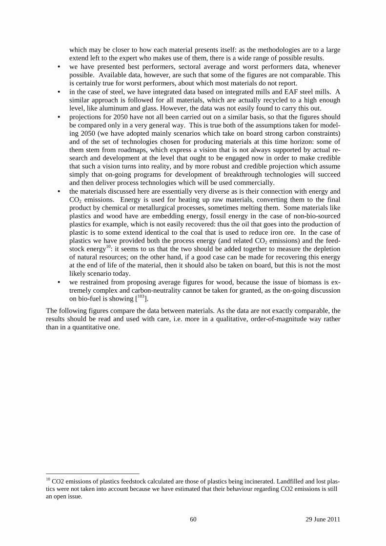
60 29 June 2011
which may be closer to how each material presents itself: as the methodologies are to a large extend left to the expert who makes use of them, there is a wide range of possible results.
• we have presented best performers, sectoral average and worst performers data, whenever possible. Available data, however, are such that some of the figures are not comparable. This is certainly true for worst performers, about which most materials do not report.
• in the case of steel, we have integrated data based on integrated mills and EAF steel mills. A similar approach is followed for all materials, which are actually recycled to a high enough level, like aluminum and glass. However, the data was not easily found to carry this out.
• projections for 2050 have not all been carried out on a similar basis, so that the figures should be compared only in a very general way. This is true both of the assumptions taken for model-ing 2050 (we have adopted mainly scenarios which take on board strong carbon constraints) and of the set of technologies chosen for producing materials at this time horizon: some of them stem from roadmaps, which express a vision that is not always supported by actual re-search and development at the level that ought to be engaged now in order to make credible that such a vision turns into reality, and by more robust and credible projection which assume simply that on-going programs for development of breakthrough technologies will succeed and then deliver process technologies which will be used commercially.
• the materials discussed here are essentially very diverse as is their connection with energy and CO2 emissions. Energy is used for heating up raw materials, converting them to the final product by chemical or metallurgical processes, sometimes melting them. Some materials like plastics and wood have are embedding energy, fossil energy in the case of non-bio-sourced plastics for example, which is not easily recovered: thus the oil that goes into the production of plastic is to some extend identical to the coal that is used to reduce iron ore. In the case of plastics we have provided both the process energy (and related CO2 emissions) and the feed-stock energy10: it seems to us that the two should be added together to measure the depletion of natural resources; on the other hand, if a good case can be made for recovering this energy at the end of life of the material, then it should also be taken on board, but this is not the most likely scenario today.
• we restrained from proposing average figures for wood, because the issue of biomass is ex-tremely complex and carbon-neutrality cannot be taken for granted, as the on-going discussion on bio-fuel is showing [103].
The following figures compare the data between materials. As the data are not exactly comparable, the results should be read and used with care, i.e. more in a qualitative, order-of-magnitude way rather than in a quantitative one.
10 CO2 emissions of plastics feedstock calculated are those of plastics being incinerated. Landfilled and lost plas-tics were not taken into account because we have estimated that their behaviour regarding CO2 emissions is still an open issue.
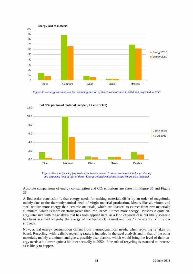
61 29 June 2011
0
10
20
30
40
50
60
70
80
90
100
Steel Aluminum Glass Clinker Plastics
Energy 2010
Energy 2050
Energy GJ/t of material
Figure 35 – energy consumption for producing one ton of structural materials in 2010 and projected in 2050
0,0
2,0
4,0
6,0
8,0
10,0
12,0
Steel Aluminum Glass Clinker Plastics
CO2 2010t
CO2 2050
t of CO2 per ton of material (scope I, II + end of life)
Figure 36 – specific CO2 (equivalent) emissions related to structural materials for producing
and disposing (end of life) of them. Energy-related emissions (scope II) are also included.
Absolute comparisons of energy consumption and CO2 emissions are shown in Figure 35 and Figure 36.
A first order conclusion is that energy needs for making materials differ by an order of magnitude, mainly due to the thermodynamical need of virgin material production. Metals like aluminum and steel require more energy than ceramic materials, which are "easier" to extract from raw materials; aluminum, which is more electronegative than iron, needs 5 times more energy. Plastics is quite en-ergy intensive with the analysis that has been applied here, as a kind of worst case but likely scenario has been assumed whereby the energy of the feedstock is used and "lost" (the exergy is fully de-stroyed).
Now, actual energy consumption differs from thermodynamical needs, when recycling is taken on board. Recycling, with realistic recycling rates, is included in the steel analysis and in that of the other materials, mainly aluminum and glass, possibly also plastics, which would bring the level of their en-ergy needs a bit lower, quite a bit lower actually in 2050, if the role of recycling is assumed to increase as is likely to happen.
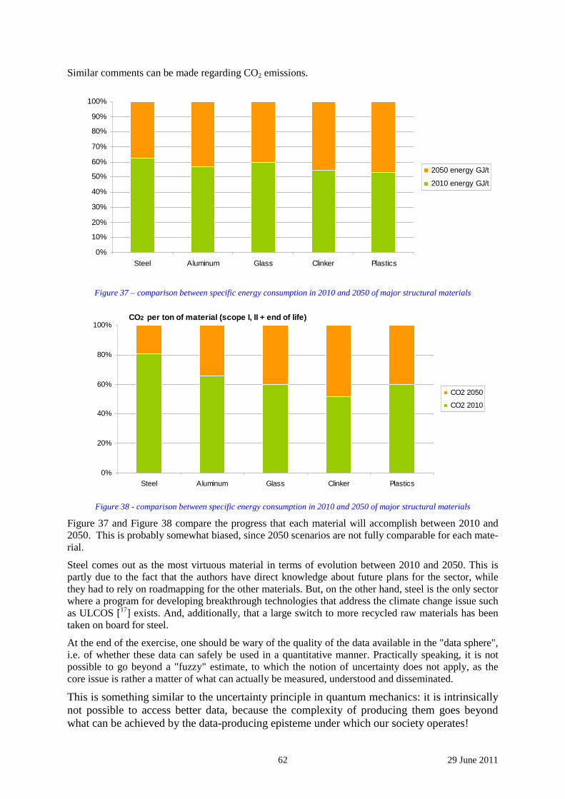
62 29 June 2011
Similar comments can be made regarding CO2 emissions.
0%
10%
20%
30%
40%
50%
60%
70%
80%
90%
100%
Steel Aluminum Glass Clinker Plastics
2050 energy GJ/t
2010 energy GJ/t
Figure 37 – comparison between specific energy consumption in 2010 and 2050 of major structural materials
0%
20%
40%
60%
80%
100%
Steel Aluminum Glass Clinker Plastics
CO2 2050
CO2 2010
CO2 per ton of material (scope I, II + end of life)
Figure 38 - comparison between specific energy consumption in 2010 and 2050 of major structural materials
Figure 37 and Figure 38 compare the progress that each material will accomplish between 2010 and 2050. This is probably somewhat biased, since 2050 scenarios are not fully comparable for each mate-rial.
Steel comes out as the most virtuous material in terms of evolution between 2010 and 2050. This is partly due to the fact that the authors have direct knowledge about future plans for the sector, while they had to rely on roadmapping for the other materials. But, on the other hand, steel is the only sector where a program for developing breakthrough technologies that address the climate change issue such as ULCOS [17] exists. And, additionally, that a large switch to more recycled raw materials has been taken on board for steel.
At the end of the exercise, one should be wary of the quality of the data available in the "data sphere", i.e. of whether these data can safely be used in a quantitative manner. Practically speaking, it is not possible to go beyond a "fuzzy" estimate, to which the notion of uncertainty does not apply, as the core issue is rather a matter of what can actually be measured, understood and disseminated.
This is something similar to the uncertainty principle in quantum mechanics: it is intrinsically not possible to access better data, because the complexity of producing them goes beyond what can be achieved by the data-producing episteme under which our society operates!
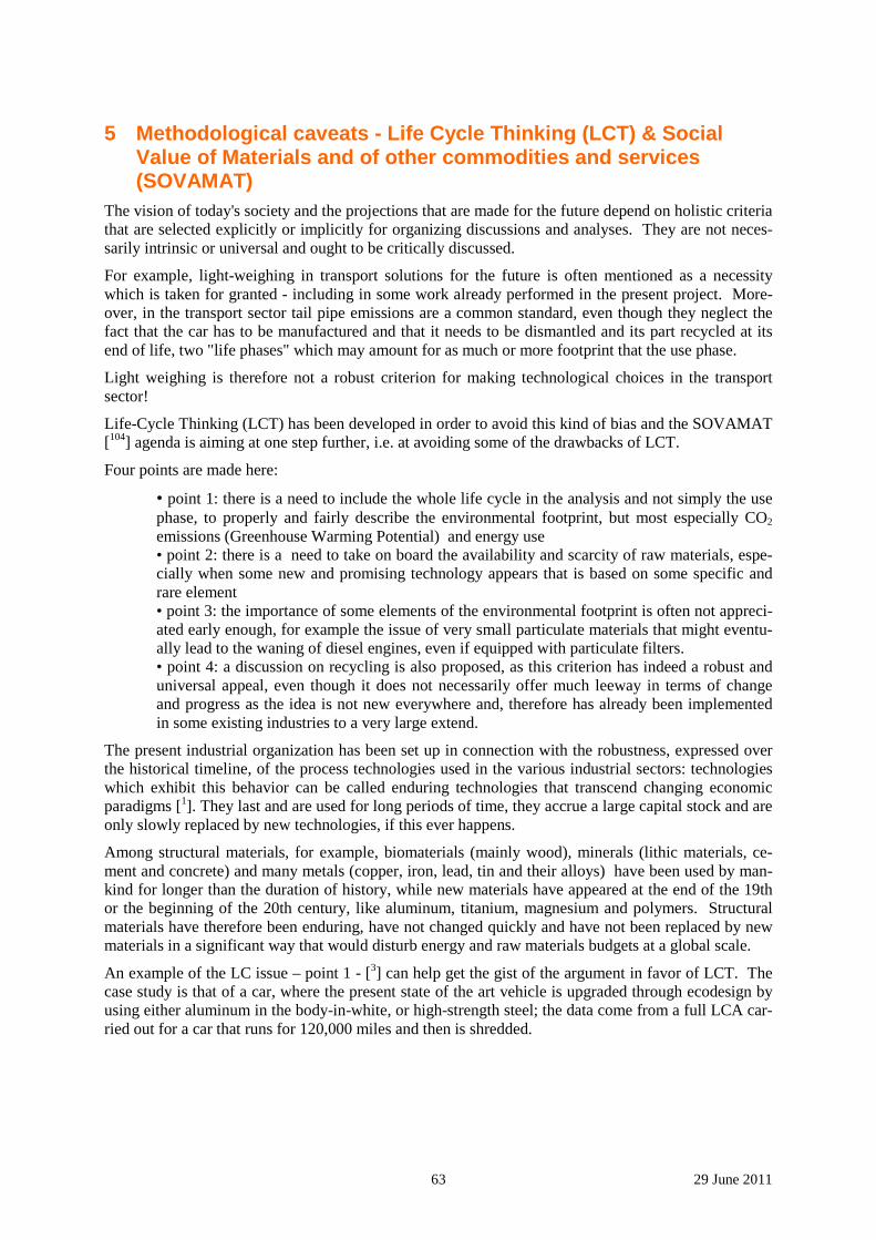
63 29 June 2011
5 Methodological caveats - Life Cycle Thinking (LCT) & Social Value of Materials and of other commodities and services (SOVAMAT)
The vision of today's society and the projections that are made for the future depend on holistic criteria that are selected explicitly or implicitly for organizing discussions and analyses. They are not neces-sarily intrinsic or universal and ought to be critically discussed.
For example, light-weighing in transport solutions for the future is often mentioned as a necessity which is taken for granted - including in some work already performed in the present project. More-over, in the transport sector tail pipe emissions are a common standard, even though they neglect the fact that the car has to be manufactured and that it needs to be dismantled and its part recycled at its end of life, two "life phases" which may amount for as much or more footprint that the use phase.
Light weighing is therefore not a robust criterion for making technological choices in the transport sector!
Life-Cycle Thinking (LCT) has been developed in order to avoid this kind of bias and the SOVAMAT [104] agenda is aiming at one step further, i.e. at avoiding some of the drawbacks of LCT.
Four points are made here:
• point 1: there is a need to include the whole life cycle in the analysis and not simply the use phase, to properly and fairly describe the environmental footprint, but most especially CO2 emissions (Greenhouse Warming Potential) and energy use • point 2: there is a need to take on board the availability and scarcity of raw materials, espe-cially when some new and promising technology appears that is based on some specific and rare element • point 3: the importance of some elements of the environmental footprint is often not appreci-ated early enough, for example the issue of very small particulate materials that might eventu-ally lead to the waning of diesel engines, even if equipped with particulate filters. • point 4: a discussion on recycling is also proposed, as this criterion has indeed a robust and universal appeal, even though it does not necessarily offer much leeway in terms of change and progress as the idea is not new everywhere and, therefore has already been implemented in some existing industries to a very large extend.
The present industrial organization has been set up in connection with the robustness, expressed over the historical timeline, of the process technologies used in the various industrial sectors: technologies which exhibit this behavior can be called enduring technologies that transcend changing economic paradigms [1]. They last and are used for long periods of time, they accrue a large capital stock and are only slowly replaced by new technologies, if this ever happens.
Among structural materials, for example, biomaterials (mainly wood), minerals (lithic materials, ce-ment and concrete) and many metals (copper, iron, lead, tin and their alloys) have been used by man-kind for longer than the duration of history, while new materials have appeared at the end of the 19th or the beginning of the 20th century, like aluminum, titanium, magnesium and polymers. Structural materials have therefore been enduring, have not changed quickly and have not been replaced by new materials in a significant way that would disturb energy and raw materials budgets at a global scale.
An example of the LC issue – point 1 - [3] can help get the gist of the argument in favor of LCT. The case study is that of a car, where the present state of the art vehicle is upgraded through ecodesign by using either aluminum in the body-in-white, or high-strength steel; the data come from a full LCA car-ried out for a car that runs for 120,000 miles and then is shredded.
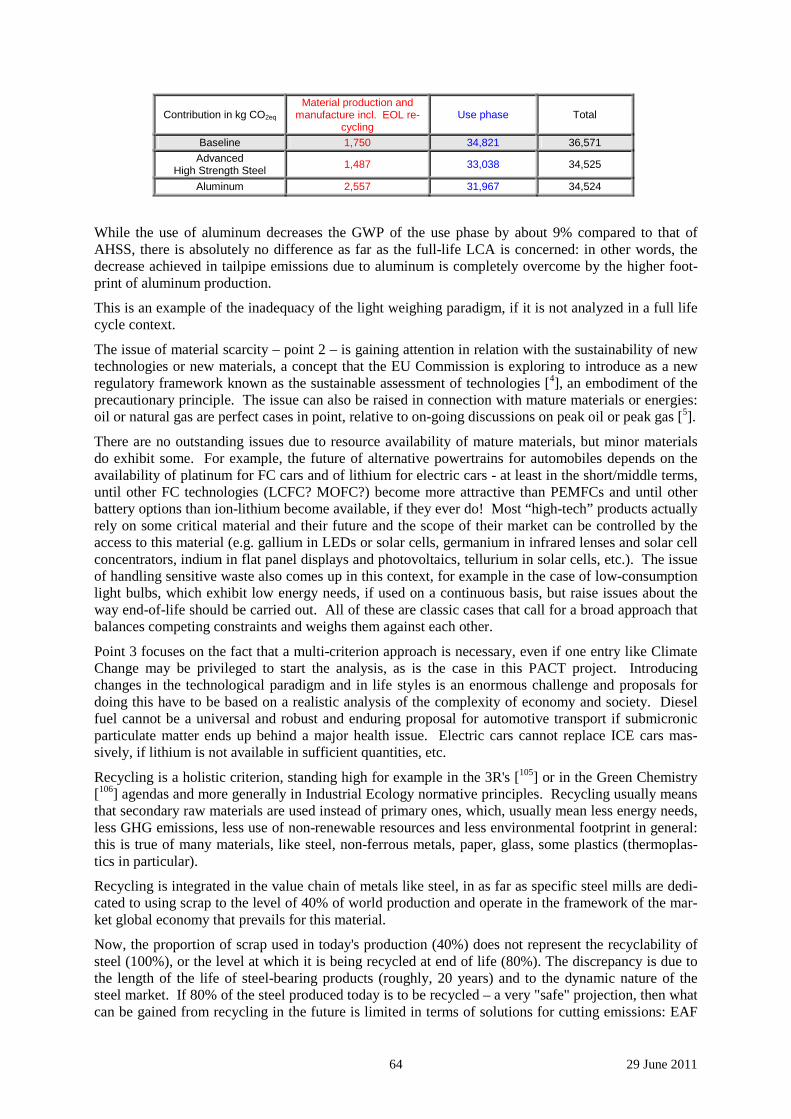
64 29 June 2011
Contribution in kg CO2eq Material production and
manufacture incl. EOL re-cycling
Use phase Total
Baseline 1,750 34,821 36,571
Advanced High Strength Steel
1,487 33,038 34,525
Aluminum 2,557 31,967 34,524
While the use of aluminum decreases the GWP of the use phase by about 9% compared to that of AHSS, there is absolutely no difference as far as the full-life LCA is concerned: in other words, the decrease achieved in tailpipe emissions due to aluminum is completely overcome by the higher foot-print of aluminum production.
This is an example of the inadequacy of the light weighing paradigm, if it is not analyzed in a full life cycle context.
The issue of material scarcity – point 2 – is gaining attention in relation with the sustainability of new technologies or new materials, a concept that the EU Commission is exploring to introduce as a new regulatory framework known as the sustainable assessment of technologies [4], an embodiment of the precautionary principle. The issue can also be raised in connection with mature materials or energies: oil or natural gas are perfect cases in point, relative to on-going discussions on peak oil or peak gas [5].
There are no outstanding issues due to resource availability of mature materials, but minor materials do exhibit some. For example, the future of alternative powertrains for automobiles depends on the availability of platinum for FC cars and of lithium for electric cars - at least in the short/middle terms, until other FC technologies (LCFC? MOFC?) become more attractive than PEMFCs and until other battery options than ion-lithium become available, if they ever do! Most “high-tech” products actually rely on some critical material and their future and the scope of their market can be controlled by the access to this material (e.g. gallium in LEDs or solar cells, germanium in infrared lenses and solar cell concentrators, indium in flat panel displays and photovoltaics, tellurium in solar cells, etc.). The issue of handling sensitive waste also comes up in this context, for example in the case of low-consumption light bulbs, which exhibit low energy needs, if used on a continuous basis, but raise issues about the way end-of-life should be carried out. All of these are classic cases that call for a broad approach that balances competing constraints and weighs them against each other.
Point 3 focuses on the fact that a multi-criterion approach is necessary, even if one entry like Climate Change may be privileged to start the analysis, as is the case in this PACT project. Introducing changes in the technological paradigm and in life styles is an enormous challenge and proposals for doing this have to be based on a realistic analysis of the complexity of economy and society. Diesel fuel cannot be a universal and robust and enduring proposal for automotive transport if submicronic particulate matter ends up behind a major health issue. Electric cars cannot replace ICE cars mas-sively, if lithium is not available in sufficient quantities, etc.
Recycling is a holistic criterion, standing high for example in the 3R's [105] or in the Green Chemistry [106] agendas and more generally in Industrial Ecology normative principles. Recycling usually means that secondary raw materials are used instead of primary ones, which, usually mean less energy needs, less GHG emissions, less use of non-renewable resources and less environmental footprint in general: this is true of many materials, like steel, non-ferrous metals, paper, glass, some plastics (thermoplas-tics in particular).
Recycling is integrated in the value chain of metals like steel, in as far as specific steel mills are dedi-cated to using scrap to the level of 40% of world production and operate in the framework of the mar-ket global economy that prevails for this material.
Now, the proportion of scrap used in today's production (40%) does not represent the recyclability of steel (100%), or the level at which it is being recycled at end of life (80%). The discrepancy is due to the length of the life of steel-bearing products (roughly, 20 years) and to the dynamic nature of the steel market. If 80% of the steel produced today is to be recycled – a very "safe" projection, then what can be gained from recycling in the future is limited in terms of solutions for cutting emissions: EAF

65 29 June 2011
production capacity will adapt dynamically to the extra supply of scrap made available when the steel produced since the beginning of this century "dies".
The proportion of scrap use will increase with time – projections are at 60% in 2050, but when will we reach a closed-loop society? Not in 2050 and possibly not until the population reaches its peak and steel production does as well. The shape of the peaks will be very important to project what happens afterwards, in terms of the capacity of scrap to meet the demand for steel. The most likely conclusion is that a close loop society, as far as steel is concerned, may end up being closed at possibly about 80% and will reach that level at the end of the century and possibly afterwards [107].
66 29 June 2011
6 Appendices regarding CO2 and energy intensity of structural materials
This section includes small monographs related to materials covered in this report, namely: Steel, Ce-ment, Plastics, or references to this kind of monograph. Aluminum, Glass and Wood are treated in the core of the text.
It should be stressed here again that the data collected originate from various sources, which do not exactly follow the same methodologies and thus do not carry the same meaning. Most of reasons for these discrepancies have been outlined in section 5.
67 29 June 2011
6.1 Steel Steel is one of the first completely artificial materials that has to be "extracted" from the environment as it does not exist in a "native" form. This is carried out by extractive metallurgy, a concept and a se-ries of technologies that represent a major breakthrough in the history (and prehistory) of mankind. Steel has been extracted from "earths" (ores in modern language), by a high temperature chemical process which has led, step by step, to the modern Blast Furnace (chemical or metallurgical reduction).
The modern Steel Industry is unique in its core processes, because of the specific nature of iron, mainly its relative abundance on Earth (planet core, planet crust and ores), its high melting point (1534°C) and the strength of the chemical bond between iron and oxygen in the major iron ores, which are oxides. Steel technologies have been used to produce other high temperature metals, like zinc, manganese, nickel, chromium, etc. and not the other way round:
Today, there are three process routes to produce steel:
• the virgin route, based on the reduction of iron ores using coal as a carbon/reducing agent source. This is called Smelting Reduction (SR). The major SR process is the Blast Furnace (BF), the principle of which consists in using pyrolyzed coal (coke, i.e. almost pure carbon) as a reducing agent in a counter flow gas-solid fixed bed reactor. The modern BF is a sophisti-cated industrial process, which one of the largest chemical/metallurgical reactors in terms of power, temperature and output: it is a high tech product of modern engineering expertise, which is highly optimized, in terms of energy consumption in particular. There are other SR processes, but they do not account for any significant part of world steel production, such as COREX, FINEX, HISMELT, etc., hic et nunc. SR produces carbon-saturated iron, called pig iron or hot metal, which needs to be "refined" into steel (i.e. decarbonized), generated in a liq-uid state. Steel is then solidified, mainly in a continuous process called Continuous Casting, and then rolled or otherwise formed into the shape of the intermediary products (plates, coils, bars, wires, rails, beams, etc.) that are sold by the Steel industry to its customers; this is done by high temperature plasticity (hot rolling) but also by room temperature deformation (cold rolling, wire drawing, etc.).
• another virgin route, based on the reduction of iron ores by natural gas, or, rather, by reduc-ing gas (syngas) produced by reforming natural gas. It is called direct reduction. The inter-mediary products it generates are directly-reduced pellets (DRI, Direct Reduced Iron, HBI), which are then melted in an Electric Arc Furnace (EAF) to produce liquid steel. Then the processes are the same as in the previous case.
• the recycling or scrap route, based on secondary raw material originating from the recovery of end of life steel. This scrap is melted in an EAF, hence the name of EAF route as opposed to the BF route, which produces liquid steel directly, which is then handled by further proc-esses already described above. This route is much less energy intensive (1/4) than the SR and BF routes, because steel is only heated up and melted, with no chemical reduction taking place.
• there are other minor routes, either about to disappear (Open Hearth Furnaces), or very confi-dential. Interesting as some might be to steel experts, they do not matter for the present PACT analysis.
The Steel sector has been fairly original compared to other material sectors in as far as recycling has been carried out for a long time at a very high level (recycling rate of 85% of more of the materials in artefacts reaching end of life) under economic conditions, which are mostly handled by market forces as they create business value. This has led to the erection of specific steel mills, once called mini-mills in contrast to the integrated steel mills based on BF, which use scrap. These mills compete with integrated mills rather fiercely, although, over the long time, prices equilibrate between the two routes to produce steel at roughly the same cost.
The proportion of integrated vs EAF mills is not simply equal to the recycling rate, because the life-in-use of artefacts containing steel varies from weeks (cans) to almost a century (buildings). The average
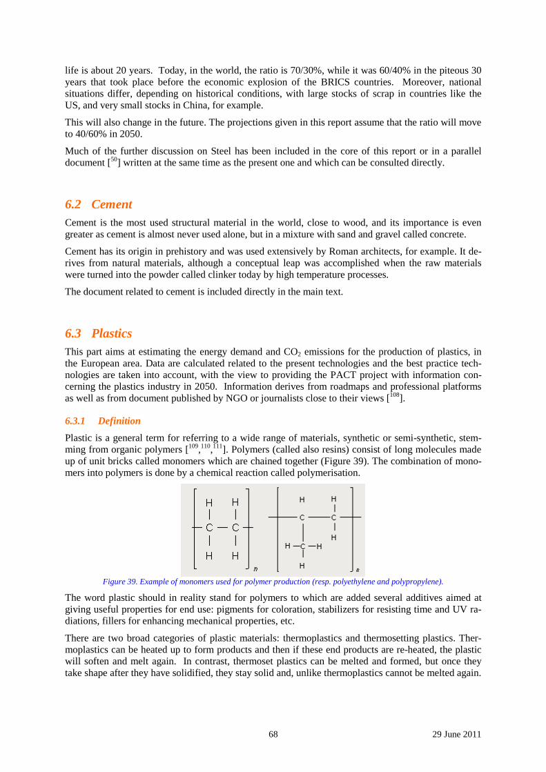
68 29 June 2011
life is about 20 years. Today, in the world, the ratio is 70/30%, while it was 60/40% in the piteous 30 years that took place before the economic explosion of the BRICS countries. Moreover, national situations differ, depending on historical conditions, with large stocks of scrap in countries like the US, and very small stocks in China, for example.
This will also change in the future. The projections given in this report assume that the ratio will move to 40/60% in 2050.
Much of the further discussion on Steel has been included in the core of this report or in a parallel document [50] written at the same time as the present one and which can be consulted directly.
6.2 Cement Cement is the most used structural material in the world, close to wood, and its importance is even greater as cement is almost never used alone, but in a mixture with sand and gravel called concrete.
Cement has its origin in prehistory and was used extensively by Roman architects, for example. It de-rives from natural materials, although a conceptual leap was accomplished when the raw materials were turned into the powder called clinker today by high temperature processes.
The document related to cement is included directly in the main text.
6.3 Plastics This part aims at estimating the energy demand and CO2 emissions for the production of plastics, in the European area. Data are calculated related to the present technologies and the best practice tech-nologies are taken into account, with the view to providing the PACT project with information con-cerning the plastics industry in 2050. Information derives from roadmaps and professional platforms as well as from document published by NGO or journalists close to their views [108].
6.3.1 Definition
Plastic is a general term for referring to a wide range of materials, synthetic or semi-synthetic, stem-ming from organic polymers [109,110,111]. Polymers (called also resins) consist of long molecules made up of unit bricks called monomers which are chained together (Figure 39). The combination of mono-mers into polymers is done by a chemical reaction called polymerisation.
Figure 39. Example of monomers used for polymer production (resp. polyethylene and polypropylene).
The word plastic should in reality stand for polymers to which are added several additives aimed at giving useful properties for end use: pigments for coloration, stabilizers for resisting time and UV ra-diations, fillers for enhancing mechanical properties, etc.
There are two broad categories of plastic materials: thermoplastics and thermosetting plastics. Ther-moplastics can be heated up to form products and then if these end products are re-heated, the plastic will soften and melt again. In contrast, thermoset plastics can be melted and formed, but once they take shape after they have solidified, they stay solid and, unlike thermoplastics cannot be melted again.
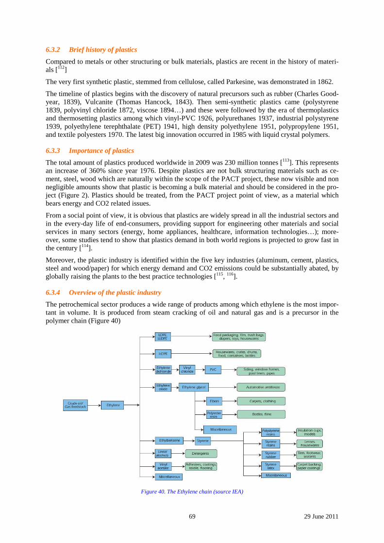
69 29 June 2011
6.3.2 Brief history of plastics
Compared to metals or other structuring or bulk materials, plastics are recent in the history of materi-als [112]
The very first synthetic plastic, stemmed from cellulose, called Parkesine, was demonstrated in 1862.
The timeline of plastics begins with the discovery of natural precursors such as rubber (Charles Good-year, 1839), Vulcanite (Thomas Hancock, 1843). Then semi-synthetic plastics came (polystyrene 1839, polyvinyl chloride 1872, viscose 1894…) and these were followed by the era of thermoplastics and thermosetting plastics among which vinyl-PVC 1926, polyurethanes 1937, industrial polystyrene 1939, polyethylene terephthalate (PET) 1941, high density polyethylene 1951, polypropylene 1951, and textile polyesters 1970. The latest big innovation occurred in 1985 with liquid crystal polymers.
6.3.3 Importance of plastics
The total amount of plastics produced worldwide in 2009 was 230 million tonnes [113]. This represents an increase of 360% since year 1976. Despite plastics are not bulk structuring materials such as ce-ment, steel, wood which are naturally within the scope of the PACT project, these now visible and non negligible amounts show that plastic is becoming a bulk material and should be considered in the pro-ject (Figure 2). Plastics should be treated, from the PACT project point of view, as a material which bears energy and CO2 related issues.
From a social point of view, it is obvious that plastics are widely spread in all the industrial sectors and in the every-day life of end-consumers, providing support for engineering other materials and social services in many sectors (energy, home appliances, healthcare, information technologies…); more-over, some studies tend to show that plastics demand in both world regions is projected to grow fast in the century [114].
Moreover, the plastic industry is identified within the five key industries (aluminum, cement, plastics, steel and wood/paper) for which energy demand and CO2 emissions could be substantially abated, by globally raising the plants to the best practice technologies [115, 116].
6.3.4 Overview of the plastic industry
The petrochemical sector produces a wide range of products among which ethylene is the most impor-tant in volume. It is produced from steam cracking of oil and natural gas and is a precursor in the polymer chain (Figure 40)
Figure 40. The Ethylene chain (source IEA)
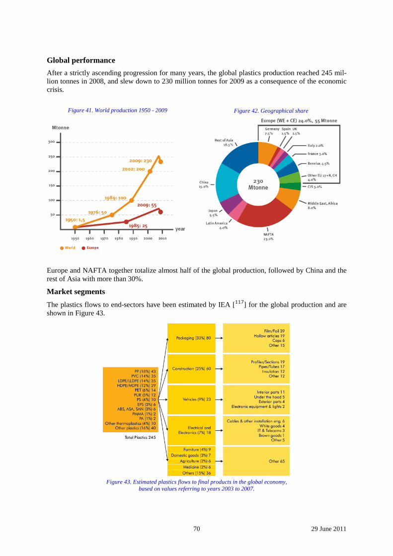
70 29 June 2011
Global performance
After a strictly ascending progression for many years, the global plastics production reached 245 mil-lion tonnes in 2008, and slew down to 230 million tonnes for 2009 as a consequence of the economic crisis.
Figure 41. World production 1950 - 2009
Figure 42. Geographical share
Europe and NAFTA together totalize almost half of the global production, followed by China and the rest of Asia with more than 30%.
Market segments
The plastics flows to end-sectors have been estimated by IEA [117] for the global production and are shown in Figure 43.
Figure 43. Estimated plastics flows to final products in the global economy,
based on values referring to years 2003 to 2007.
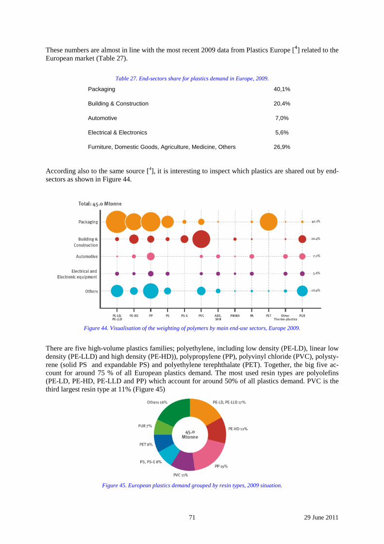
71 29 June 2011
These numbers are almost in line with the most recent 2009 data from Plastics Europe [4] related to the European market (Table 27).
Table 27. End-sectors share for plastics demand in Europe, 2009.
Packaging 40,1%
Building & Construction 20,4%
Automotive 7,0%
Electrical & Electronics 5,6%
Furniture, Domestic Goods, Agriculture, Medicine, Others 26,9%
According also to the same source [4], it is interesting to inspect which plastics are shared out by end-sectors as shown in Figure 44.
Figure 44. Visualisation of the weighting of polymers by main end-use sectors, Europe 2009.
There are five high-volume plastics families; polyethylene, including low density (PE-LD), linear low density (PE-LLD) and high density (PE-HD)), polypropylene (PP), polyvinyl chloride (PVC), polysty-rene (solid PS and expandable PS) and polyethylene terephthalate (PET). Together, the big five ac-count for around 75 % of all European plastics demand. The most used resin types are polyolefins (PE-LD, PE-HD, PE-LLD and PP) which account for around 50% of all plastics demand. PVC is the third largest resin type at 11% (Figure 45)
Figure 45. European plastics demand grouped by resin types, 2009 situation.
72 29 June 2011
Previous data are useful for classifying the plastics products according to end-sector view and poly-mer/resin view, so that it can help to decide which are the most important data to retrieve within the scope of the present study. As PACT project will use key drivers for estimating plastics demand, part of the answer could be given by such classification. Social services described in PACT should drive the demand.
6.3.5 Energy demand for plastics production
Methodology adopted
Calculations have been derived from the following data sources:
- BPT (Best Practices Techniques), from IEA [117]
- BAT (Best Available Techniques), from IPPC Europe [118]
- Current average technologies:
* A study on petrochemical key processes [119]
* the polymer Eco-profiles from PlasticsEurope [120]
* the Ecoinvent database [121]
Have been taken into account:
- the process final energy demand (direct energy consumption of the polymer production chain)
- the Cradle to Gate aspect which gives values for the production from primary resources (oil, natural gas) up to the polymer manufacturing plant.
This double point of view is useful because it enables to compare the respective weights of the de-mand due to the processes themselves and the energy embodied in the polymers used as physical mat-ter which depletes natural fuel resources.
Energy demand profile
A group of results are carried out , representing 87% of the European polymer production. Data are mainly broken down into:
- the main polymer manufacturing processes
- the life cycle view of the polymer production routes (i.e. from primary resources to the deliv-ery of the polymers at the plant gate).
The total energy demand, as well as the CO2-equivalent emissions (CO2e), is calculated at the Euro-pean global level of production, based on the 2007 reference year. Considered are the process direct consumption and emissions, the cradle to gate ones, and the total feedstock which will end its life by incineration, landfilling, or recycling.
Average current technologies
The process chain is composed of:
• upstream steps which are oil extraction and refining, steam cracking, precursors gases, high value chemicals and feedstock that will be transformed into monomers
• the polymerization process itself which produces polymers from monomers.
The cradle to gate view gives the total energy demand when all consuming processes and activities are accounted for: oil and gas beneficiation, energy consumed for fuel production, transport, energy bear-ing chemicals used as feedstock, direct consumption of energy by the processes in the chain.
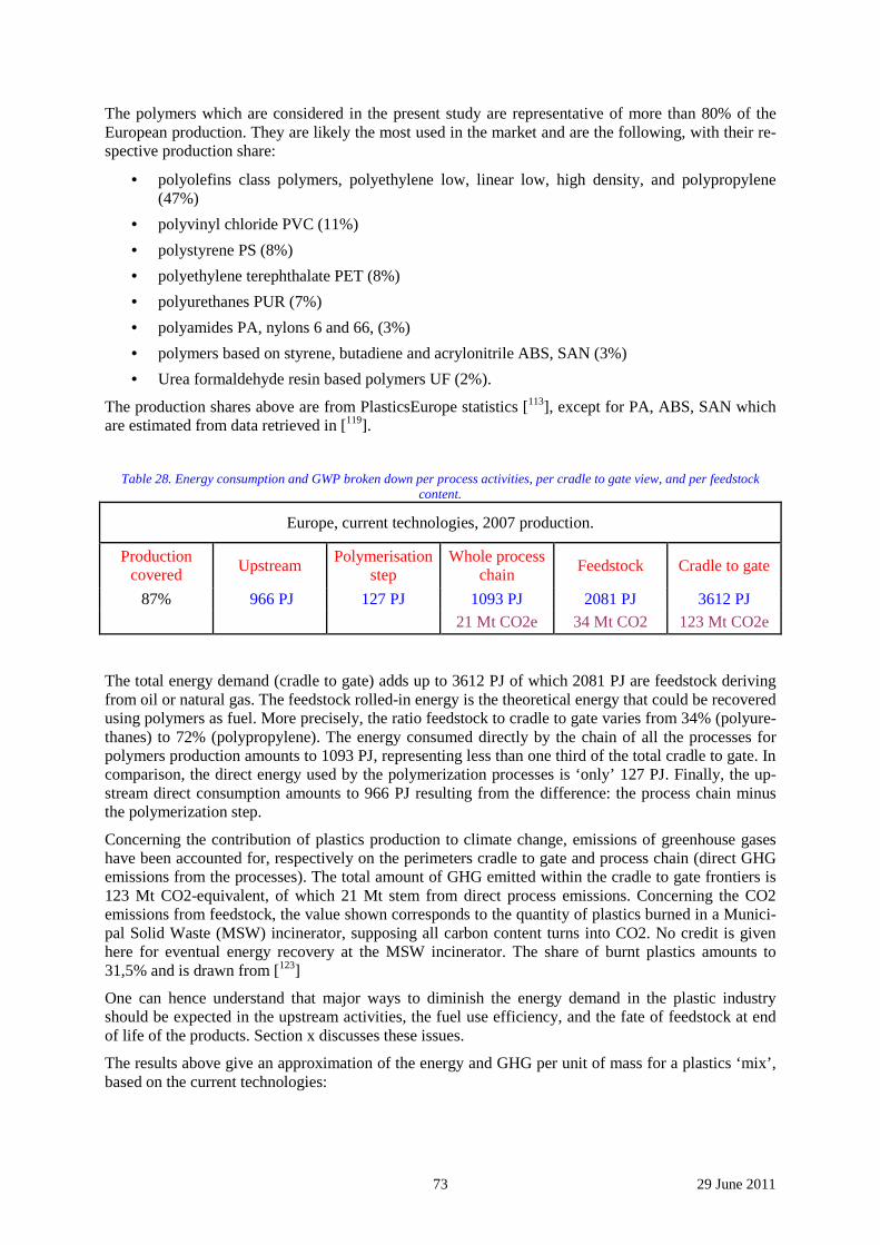
73 29 June 2011
The polymers which are considered in the present study are representative of more than 80% of the European production. They are likely the most used in the market and are the following, with their re-spective production share:
• polyolefins class polymers, polyethylene low, linear low, high density, and polypropylene (47%)
• polyvinyl chloride PVC (11%)
• polystyrene PS (8%)
• polyethylene terephthalate PET (8%)
• polyurethanes PUR (7%)
• polyamides PA, nylons 6 and 66, (3%)
• polymers based on styrene, butadiene and acrylonitrile ABS, SAN (3%)
• Urea formaldehyde resin based polymers UF (2%).
The production shares above are from PlasticsEurope statistics [113], except for PA, ABS, SAN which are estimated from data retrieved in [119].
Table 28. Energy consumption and GWP broken down per process activities, per cradle to gate view, and per feedstock content.
Europe, current technologies, 2007 production.
Production covered
Upstream Polymerisation
step Whole process
chain Feedstock Cradle to gate
87% 966 PJ 127 PJ 1093 PJ 2081 PJ 3612 PJ 21 Mt CO2e 34 Mt CO2 123 Mt CO2e
The total energy demand (cradle to gate) adds up to 3612 PJ of which 2081 PJ are feedstock deriving from oil or natural gas. The feedstock rolled-in energy is the theoretical energy that could be recovered using polymers as fuel. More precisely, the ratio feedstock to cradle to gate varies from 34% (polyure-thanes) to 72% (polypropylene). The energy consumed directly by the chain of all the processes for polymers production amounts to 1093 PJ, representing less than one third of the total cradle to gate. In comparison, the direct energy used by the polymerization processes is ‘only’ 127 PJ. Finally, the up-stream direct consumption amounts to 966 PJ resulting from the difference: the process chain minus the polymerization step.
Concerning the contribution of plastics production to climate change, emissions of greenhouse gases have been accounted for, respectively on the perimeters cradle to gate and process chain (direct GHG emissions from the processes). The total amount of GHG emitted within the cradle to gate frontiers is 123 Mt CO2-equivalent, of which 21 Mt stem from direct process emissions. Concerning the CO2 emissions from feedstock, the value shown corresponds to the quantity of plastics burned in a Munici-pal Solid Waste (MSW) incinerator, supposing all carbon content turns into CO2. No credit is given here for eventual energy recovery at the MSW incinerator. The share of burnt plastics amounts to 31,5% and is drawn from [123]
One can hence understand that major ways to diminish the energy demand in the plastic industry should be expected in the upstream activities, the fuel use efficiency, and the fate of feedstock at end of life of the products. Section x discusses these issues.
The results above give an approximation of the energy and GHG per unit of mass for a plastics ‘mix’, based on the current technologies:
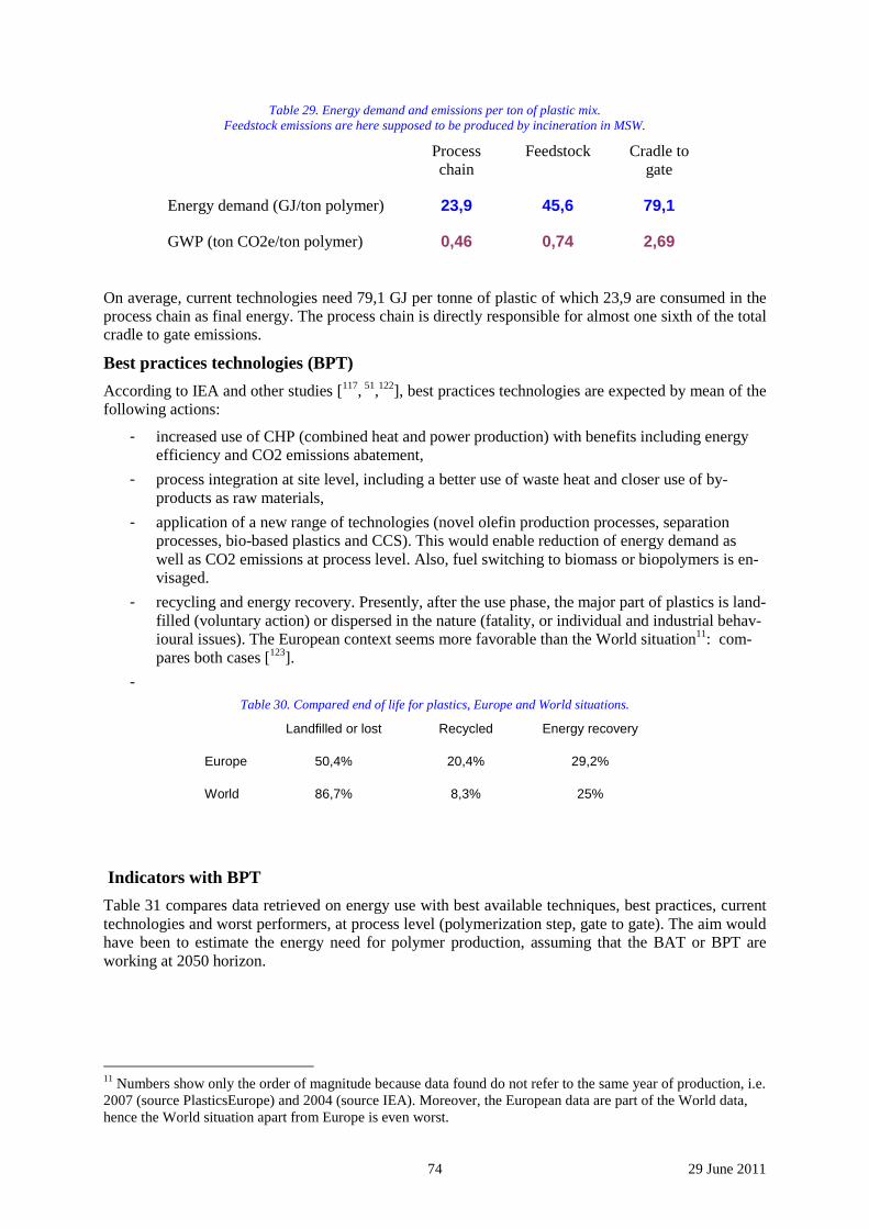
74 29 June 2011
Table 29. Energy demand and emissions per ton of plastic mix. Feedstock emissions are here supposed to be produced by incineration in MSW.
Process chain
Feedstock Cradle to gate
Energy demand (GJ/ton polymer) 23,9 45,6 79,1
GWP (ton CO2e/ton polymer) 0,46 0,74 2,69
On average, current technologies need 79,1 GJ per tonne of plastic of which 23,9 are consumed in the process chain as final energy. The process chain is directly responsible for almost one sixth of the total cradle to gate emissions.
Best practices technologies (BPT)
According to IEA and other studies [117, 51,122], best practices technologies are expected by mean of the following actions:
- increased use of CHP (combined heat and power production) with benefits including energy efficiency and CO2 emissions abatement,
- process integration at site level, including a better use of waste heat and closer use of by-products as raw materials,
- application of a new range of technologies (novel olefin production processes, separation processes, bio-based plastics and CCS). This would enable reduction of energy demand as well as CO2 emissions at process level. Also, fuel switching to biomass or biopolymers is en-visaged.
- recycling and energy recovery. Presently, after the use phase, the major part of plastics is land-filled (voluntary action) or dispersed in the nature (fatality, or individual and industrial behav-ioural issues). The European context seems more favorable than the World situation11: com-pares both cases [123].
- Table 30. Compared end of life for plastics, Europe and World situations.
Landfilled or lost Recycled Energy recovery
Europe 50,4% 20,4% 29,2%
World 86,7% 8,3% 25%
Indicators with BPT
Table 31 compares data retrieved on energy use with best available techniques, best practices, current technologies and worst performers, at process level (polymerization step, gate to gate). The aim would have been to estimate the energy need for polymer production, assuming that the BAT or BPT are working at 2050 horizon.
11 Numbers show only the order of magnitude because data found do not refer to the same year of production, i.e. 2007 (source PlasticsEurope) and 2004 (source IEA). Moreover, the European data are part of the World data, hence the World situation apart from Europe is even worst.
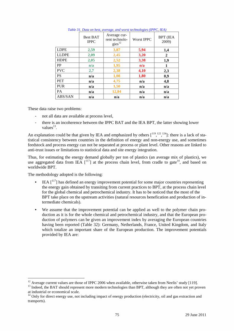
75 29 June 2011
Table 31. Data on best, average, and worst technologies (IPPC, IEA)
Best BAT IPPC
Average cur-rent technolo-
gies12 Worst IPPC
BPT (IEA 2009)
LDPE 2,59 3,87 5,94 1,4 LLDPE 2,09 2,45 3,20 2 HDPE 2,05 2,52 3,38 1,9 PP n/a 1,95 n/a 1 PVC 2,7 2,38 4,10 2,3 PS n/a 1,08 1,80 0,9 PET n/a 4,75 n/a 4,8 PUR n/a 1,50 n/a n/a PA n/a 12,04 n/a n/a ABS/SAN n/a n/a n/a n/a
These data raise two problems:
- not all data are available at process level,
- there is an incoherence between the IPPC BAT and the IEA BPT, the latter showing lower values13.
An explanation could be that given by IEA and emphasized by others [119,122,124]: there is a lack of sta-tistical consistency between countries in the definition of energy and non-energy use, and sometimes feedstock and process energy can not be separated at process or plant level. Other reasons are linked to anti-trust issues or limitations to statistical data and site energy integration.
Thus, for estimating the energy demand globally per ton of plastics (an average mix of plastics), we use aggregated data from IEA [117] at the process chain level, from cradle to gate14, and based on worldwide BPT.
The methodology adopted is the following:
• IEA [117] has defined an energy improvement potential for some major countries representing the energy gain obtained by transiting from current practices to BPT, at the process chain level for the global chemical and petrochemical industry. It has to be noticed that the most of the BPT take place on the upstream activities (natural resources benefication and production of in-termediate chemicals).
• We assume that the improvement potential can be applied as well to the polymer chain pro-duction as it is for the whole chemical and petrochemical industry, and that the European pro-duction of polymers can be given an improvement index by averaging the European countries having been reported (Table 32): Germany, Netherlands, France, United Kingdom, and Italy which totalize an important share of the European production. The improvement potentials provided by IEA are:
12 Average current values are those of IPPC 2006 when available, otherwise taken from Neelis’ study [119]. 13 Indeed, the BAT should represent more modern technologies than BPT, although they are often not yet proven at industrial or economical scale. 14 Only for direct energy use, not including impact of energy production (electricity, oil and gas extraction and transports).
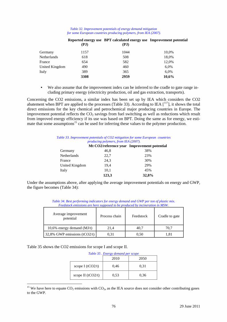
76 29 June 2011
Table 32. Improvement potentials of energy demand mitigation for some European countries producing polymers, from IEA (2007).
Reported energy use (PJ)
BPT calculated energy use (PJ)
Improvement potential
Germany 1157 1044 10,0% Netherlands 618 508 18,0% France 654 582 12,0% United Kingdom 490 460 6,0% Italy 389 365 6,0% 3308 2959 10,6%
• We also assume that the improvement index can be inferred to the cradle to gate range in-cluding primary energy (electricity production, oil and gas extraction, transports).
Concerning the CO2 emissions, a similar index has been set up by IEA which considers the CO2 abatement when BPT are applied to the processes (Table 33). According to IEA [117], it shows the total direct emissions for the key chemical and petrochemical major producing countries in Europe. The improvement potential reflects the CO2 savings from fuel switching as well as reductions which result from improved energy efficiency if its use was based on BPT. Doing the same as for energy, we esti-mate that some assumptions15 can be used for inferring these values to the polymer production.
Table 33. Improvement potentials of CO2 mitigation for some European countries producing polymers, from IEA (2007).
Mt CO2/reference year Improvement potential Germany 46,8 38% Netherlands 22,7 23% France 24,3 30% United Kingdom 19,4 29% Italy 10,1 45% 123,3 32,8%
Under the assumptions above, after applying the average improvement potentials on energy and GWP, the figure becomes (Table 34):
Table 34. Best performing indicators for energy demand and GWP per ton of plastic mix. Feedstock emissions are here supposed to be produced by incineration in MSW.
Average improvement potential
Process chain Feedstock Cradle to gate
10,6% energy demand (MJ/t) 21,4 40,7 70,7
32,8% GWP emissions (tCO2/t) 0,31 0,50 1,81
Table 35 shows the CO2 emissions for scope I and scope II.
Table 35 . Energy demand per scope
2010 2050
scope I (tCO2/t) 0,46 0,31
scope II (tCO2/t) 0,53 0,36
15 We have here to equate CO2 emissions with CO2e as the IEA source does not consider other contributing gases to the GWP.
77 29 June 2011
7 References 1 J.-P. Birat, Materials and industry, introduction to the Industry Workshop, WMP, Nancy, 30-31 March 2011
2 See, for example, the SAM seminars (Society and Materials), referenced in www.sovamat.org
3 D. Ablitzer, CNRS czar for materials, personal communication
4 JP. Birat, Alternative ways of making steel: retrospective and prospective…, Centenaire de la Revue de Métal-lurgie, Paris, le 9 décembre 2004, La Revue de Métallurgie-CIT, Novembre 2004, 937-955
5 J.-P. Birat, Materials, beyond life-cycle thinking, 24. Aachener Stahl Kolloquium, Aachen, 2009
6 M. Giget, propriétés fonctionnelles et choix des matériaux, in Le Livre de l’Acier, Techniques et Document, Lavoisier, 1994, 1492 pages
7 ArcelorMittal, own compilation, 2009
8 www.leviaducdemillau.com
9 http://skyscraperpage.com/cities/?buildingID=7787
10 Calculated from IPCC 2000 data (www.ipcc.ch) and Worldsteel data (www.worldsteel.org)
11 Étude « Scénarios sous Contrainte Carbone », FONDDRI, Fondation pour le développement durable et les re-lations internationales, Rapport Complet, Décembre 2008
12 Keigo Akimoto (Group Leader, Systems Analysis Group, Research Institute of Innovative Technology for the Earth (RITE)), Global Scenarios of Emission Reductions Toward Low Carbon Future – Iron and Steel Sector –, International Iron and Steel Institute (IISI, now worldsteel), CO2 Breakthrough Programme 8th Meeting of the Coordination Committee, Oita, Japan, September 5th, 2008
13 Worldsteel, Brussels, personal communication
14 Hatayama, Hiroki; Daigo, Ichiro; Matsuno, Yasunari; Adachi, Yoshihiro, Outlook of the world steel cycle based on the stock and flow dynamics, SAM4, Nancy, 28-29 April 2010
15 www.ulcos.org
16 Energy Technology Perspectives, 2008, scenarios and strategies to 2050, IEA, OECD/IEA, 2008, 643 pages
17 J-P. Birat, CO2 mitigation in the Steel Industry in a post-Kyoto scenario, Scanmet II, 2nd international Conference on Process Development in Iron & Steelmaking, 6-9 June 2004, Luleå, Sweden
18 A. Fallot et al., Biomass sustainability, availability and productivity, La Revue de Métallurgie-CIT, Octobre 2009, 410-418
19 Jean-Michel VIGO, Positionnement des matériaux de construction en France et en Europe, 18/11/03 (OTUA)
20 C. Vanvoren, Aluminum,Industry Workshop, WMP, Nancy, 30-31 March 2011
21 NMP Expert advisory group (EAG), Position paper on future RTD activities of NMP for the period 2010-2015, Nov.2009, EUR 24179 EN, 7th Framework Program, European Commission
78 29 June 2011
22 Arthur C. Clarke, Fountains of Paradise, 1978
23 http://science.nasa.gov/headlines/y2000/ast07sep_1.htm
24 IPCC Technical papers - Linking climate change and water resources: impacts and responses - http://www.ipcc.ch/pdf/technical-papers/ccw/chapter3.pdf (consulted Dec.9th, 2009)
25 United Nations, 2007 - World urbanisation prospects – The 2007 Revision, Department of Economic and So-cial Affairs/Population Division
26 C. Sessa, 2009 - Visioning post carbon cities of tomorrow, PACT working paper, ISIS
27 B. Bougnoux, 2009 – Transport in post-carbon societies, PACT Garching Meeting, 20 May 2009
28 EU, 2002/49/EC - Directive 2002/49/EC of the European Parliament and of the Council of 25 June 2002 relat-ing to the assessment and management of environmental noise
29 R. Ryne, 2006 - Hybrid nanomaterials improve solar cell efficiency - The International Society for Optical Engineering, http://spie.org/documents/Newsroom/Imported/371/2006080371.pdf
30 United Nations - World population prospects - The 2008 revision, Population Division (2009)
31 T.E. Graedel, Julian Allwood, Jean-Pierre Birat, Matthias Buchert, Christian Hagelüken, Christina E.M. Mes-kers, B.K. Reck1, Scott F. Sibley and Guido Sonnemann, The Recycling of Metals: A Status Report, paper pre-sented for publication to the Journal of Environmental Science (2010)
32 IARC - 10th International Automotive Recycling Congress, Basel, March 3-5, 2010
33 VLEEM 2, FINAL REPORT, 2005 - EC/DG Research, www.vleem.org
34 European Commission, 2009 - Transport and the Environment, Transport Knowledge Research Centre, www.transportresearch.info
35 L’Energie de demain - Groupe Energie de la Société Française de Physique, EDP Sciences, ISBN 2868837719
36 A. Battaglini &all, 2009 - Development of SuperSmart Grids for a more efficient utilisation of electricity from renewable sources, Journal of Cleaner Production, doi:10.1016/j.jclepro.2009.02.006
37 Elizabeth A. Thomson, MIT, 2002 - Fusion energy may be here by 2050, - Massachusetts Institute of Tech-nology, http://web.mit.edu/newsoffice/2002/aaas3-0227.html
38 CORDIS, 2008 - Nuclear fusion research takes a step forward, EU Commission, CORDIS News, http://cordis.europa.eu/news/about-service_en.html
39 R. Wiser et al., 2009 - The Installed Cost of Photovoltaics, Environmental Energy Technologies Division, Lawrence Berkeley National Laboratory, http://eetd.lbl.gov/ea/ems/re-pubs.html
40 J. Buba et al., 2009 - Le pari de l’éolien, Centre d’Analyse Stratégique, www.strategie.gouv.fr
41 EEA, 2005 - Vulnerability and adaptation to climate change in Europe, European Energy Agency Technical report 7/2005
42 TEN-T European project - http://ec.europa.eu/transport/infrastructure/index_en.htm
43 Le moteur thermique, une idée d’avenir, L’Usine Nouvelle, n°3160, pages 22-27
79 29 June 2011
44 K.U. Birnbaum, 2005 – Monograph on Fuel Cells, K.U. Birnbaum, VLEEM 2 final report, annex 3.3, www.vleem.org
45 J.Köhler, M.Jakob, R.Foster, Brief description of current technologies and their material input, - PACT, DI2.1
46 M. Girault, 2008 – Baisse des consommations d’énergies de chauffage dans les logements depuis 2001- Note de synthèse du SESP n°170, 2008 - http://www.statistiques.equipement.gouv.fr/
47 EU Green, 2009 - The Expert Panel's Evaluation Work & Final Recommendations for the European Green Capital Award of 2010 and 2011, - European Commission, Environment, 2009
48 PACT, DI1.1 – Urbanisation schemes and related urban infrastructures for energy & transport in post-carbon cities – S.Braun, T.Hamacher
49 Les Echos, 2009 - Toulouse teste des lampadaires à détecteur de présence – Laurent Marcaillou, 1/12/2009, http://www.lesechos.fr/info/metiers/020233913376-toulouse-teste-des-lampadaires-a-detecteur-de-presence.htm
50 JP. Birat, Steel sectoral report, UNIDO, http://www.unido.org/fileadmin/user_media/Services/Energy_and_Climate_Change/Energy_Efficiency/CCS/Stee_sectoral_%20report.pdf ; cf. the list of roadmap quoted in the reference list
51 Tracking Industrial Energy Efficiency and CO2 Emissions, Energy Indicators, pp.95-137, IEA, 2007
52 B. de Lamberterie, Some reflexions about Energy Initiatives, SET Plan Workshop on Technology Innovations for Energy Efficiency and GHG emissions reduction in the Iron & Steel Industry in the EU27. Brussels, January 15, 2010
53 Methodology for the free allocation of emission allowances in the EU ETS post 2012, Sector report for the iron and steel industry, November 2009, Ecofys, Fraunhofer Institute for EUROFER, 2009
54 Worldsteel, personal communication, June 2010
55 APP Steel task force, personal communication, June 2010 (Asian Pacific Partnership)
56 US greenhouse gas reporting, EIA, http://www.eia.doe.gov/environment.html and emissions of greenhouse gases in the United States 2008, 2009, http://www.eia.doe.gov/oiaf/1605/ggrpt/pdf/0573(2008).pdf
57 Emissions dans l'air en France métropole, Substances relatives à l’accroissement de l’effet de serre, France 2009, http://www.citepa.org/emissions/nationale/Ges/ges_co2.htm
58 The Greenhouse Gas Protocol Initiative, http://www.ghgprotocol.org/
59 Specification with guidance at the organization level for quantification and reporting of greenhouse gas emis-sions and removals, ISO 14064-1
60 J-P. Birat, concept note for the UNIDO CCS roadmap, Steel sector, June 2010
61 J.-P. Birat, J.-P. Lorrain, The "CO2 tool": emissions and energy consumption of existing and breakthrough routes in a future studies framework, La revue de Métallurgie – CIT, Septembre 2009, 325-336
62 J.-P. Birat, Materials, beyond life-cycle thinking, 24. Aachener Stahl Kolloquium, Aachen, 17-18 September 2009, proceedings
63 ArcelorMittal, unpublished data, 2008
80 29 June 2011
64 Zheng Luo, Antonio Soria. Prospective Study of the World Aluminum Industry. s.l. : JRC, 2007.
65 http://minerals.usgs.gov/minerals/pubs/commodity/bauxite/. www.usgs.gov. [Online] U.S. Geological Survey, 2010.
66 International Alumuminium Institute (IAI). Results of the 2009 Anode Effect Survey. s.l. : International Alu-muminium Institute, 2010.
67 U.S. Department of Energy. U.S. Energy Requirements for Aluminum Production. s.l. : U.S. Department of Energy, 2007.
68 Draft reference document on Bets available techniques for the Non-ferrous industry. Seville, Spain : Institute for prospective technolical studies, 2009.
69 Ernst Worrell, Lynn Price, Maarten Neelis, Christina Galitsky, Zhou Nan. World Best Practice Energy Inten-sity Values for Selected Industrial Sectors. s.l. : Ernest orlando Lawrence Berkely National Laboratory, 2008.
70 International Aluminum Institute (IAI). www.world-aluminum.org. [Online] 2010.
71 The Aluminum sector greenhouse gas protocol. s.l. : International Aluminum Insitute, 2006.
72 Lorentzen, Odd-Arne. Behaviour of nickel, iron and copper by application of inert anodes in aluminum pro-duction. Trondheim : Norwegian University of Science and Technology, 2000.
73 Inert Anodes for Al Smelters: Energy Balances and Environmental Impact. Haupin, Halvor Kvande and War-ren. s.l. : JOM, 2001, Vol. May.
74 Halmann, M. Carbothermal reduction of alumina: Thermochemical equilibrium calculations and experimental investigation. ScienceDirect. Energy 32 (2007) 2420–2427, 2004.
75 The Economics of Inert Anodes and Wettable Cathodes for Aluminum Reduction Cells. Keniry, Jeff. s.l. : JOM, 2001, Vol. May.
76 The applicability of carbon capture and sequestration in primary aluminum smelters. Broek, Stephan. s.l. : Light Metals 2010, 2010.
77 J. Ruppert, CO2 emissions from the Cement Industry, Technical developments and outlook, China-EU Work-shop on Clean Technologies, 17-17-19 March, 2010, Beijing
78 Cement Technology Roadmap, 2009, Carbon Emissions Reduction up to 2050, ,WBCSD & IEA, 2009
79 D.J. Barkera,*, S.A. Turnera, P.A. Napier-Moorea, M. Clarkb and J.E. Davisonc, CO2 Capture in the Cement Industry, Energy Procedia 00 (2008) 000–000, www.elsevier.com/locate/XXX
80 www.novacem.com
81 www.calera.com
82 www.calix.com.au/
83 www.geopolymer.org
84 Greenhouse Gas and Carbon Profile of the U.S. Forest Products Industry Value Chain. L. Heath, V. Maltby, R. Miner, K.E. Skog, J.E. Smith, J. Unwin, B. Upton. : Environvironmental Science & Technology, 2010, Vol. 44(10):3999-4005.
81 29 June 2011
85 General Technical Report FPL-GTR-190 . Madison, Wisconsin : United States Department of Agriculture Forest Service, 2010.
86 H.L. Brown, B.B. Hamel, B.A.Hedman, M. Koluch, B.C. Gajana, P. Troy. Energy analysis of 108 industrial processes. Lilburn, Georgia : Fairmont Press, 1996.
87 Gate-to-gate LCI of softwood lumber production. M.R. Milota, C.D. West, I.D. Hartley. : Wood and Fiber Science, 2005, Vol. 37: 47-57.
88 Meta-analysis of greenhouse gas displacement factors of wood product substitution. R. Sathre, J. O´Connor. : Environmental Science & Policy, 2010, Vol. 13:104-114.
89 S. John, B. Nebel, N. Perez, A. Buchanan. Environmental Impacts of Multi-Storey Buildings Using Different Construction Materials. Research report 2008-02. New Zealand : University of Canterbury, 2009.
90 The greenhouse gas and energy impacts of using wood instead of aletrnatives in residential construction in the United States. B. Upton, R. Miner, M. Spinney, L.S. Heath. : Biomass and Bioenergy, 2008, Vol. 32(1):1-10.
91 Carbon dioxide balance of wood substitution: Comparing concrete- and wood-framed buildings. L. Gustavs-son, K. Pingoud, R. Sathre. : Strategies for Global Change, 2006, Vol. 11(39):667-691.
92 Greenhouse gas emissions, life-cycle inventory and cost-efficiency of using laminated wood instead of steel construction. A.K. Petersen, B. Solberg. : Environmental Science and Policy, 2002, Vol. 5(2):169-182.
93 Agency, IEA IEE - International Energy. Tracking Industrial Energy Efficiency and CO2 Emissions. Paris : IEA/OECD, 2007.
94 Ernst Worrell, Christina Galitsky, Eric Masanet, and Wina Graus. Energy Efficiency Improvement and Cost Saving Opportunities for the Glass Industry. u.o. : Ernest Orlando Lawrence Berkeley National Laboratory, 2008.
95 Energy consumption and CO2 emissions of the European glass industry. A. Schmitz, J. Kaminski, B.M. Scalet, A Soria. (2011)142-155, u.o. : Energy Policy, Vol. 39.
96 IPPC. Reference document on best available teqniques in the glass manufacturing industry. 2001.
97 Unit, Energy Technology Support. Technology benchmarking in the UK Glass sector. Harwell, United King-dom : Energy Efficiency Best Practice Programme (EEBPP), 2000.
98 C. Philip Ross, Gabe L. Tincher, M. Rasmussen. Glass melting technology. u.o. : Glas manufacturing industry council, 2004.
99 Ecofys. Methodology for the free allocation of emission allowances in the EU ETS post 2012 - Sector report for the glass industry. u.o. : Ecofys, 2009.
100 Industrial energy efficency and climate change mitigation. E. Worrell, L. Bernstein, J. Roy, L. Price, J. Har-nish. 2:109-123, u.o. : Energy Efficiency, 2009.
101 Industrial applications of the air bottoming cycle. Korobitsyn, M. u.o. : Energy Conversion and Management, 2002, Vol. 43.
102 European Business Facts and figures. u.o. : Eurostat European commission, 2009.
103 A. Carvallo Aceves, JP. Birat, Review of biofuel LCA studies, SAM-5, Metz, 11-12 May 2011
82 29 June 2011
104 www.sovamat.org
105 http://www.epa.gov/osw/conserve/rrr/
106 http://www.epa.gov/greenchemistry/
107 Jean-Pierre Birat, Jean Borlée, Bernd Korthas, Jan van der Stel, Koen Meijer, Christian Günther, Mats Halin, Thomas Bürgler, Hervé Lavelaine, Chris Treadgold, ULCOS program: a progress report in the Spring of 2008, SCANMET III, 3rd International Conference on Process Development in Iron and Steelmaking, 8–11 June 2008, Luleå, Sweden, www.scanmet.info
108 W. Boote, G. Pretting, Plastic Planet, Die dunkle Seite der Kunstoffe, orange-press, Friburg, 2010 – La face cachée des matières plastiques, Acte Sud, questions de société, 2010
109 www.science.org.au, glossary
110 www.plasticseurope.org, what is plastic?
111 ASM International, 1988, Engineering plastics handbook, volume 2, ISBN 0-87170-280-0
112 www.americanchemistry.com, Plastics Division, The History of Plastics
113 PlasticsEurope, 2010, An analysis of European plastics production, demand and recovery for 2009
114 VLEEM 2, 2005, Final report – EC/DG Research, downloadable at www.vleem.org
115 IEA, 2008, Energy Technology Perspectives – Scenarios and Strategies to 2050
116 Allwood J.M. & al, 2010, Material efficiency: A white paper, Elsevier, doi:10.1016/j.resconrec.2010.11.002
117 IEA, 2009, Energy Technology Transition for Industry
118 European Commission, IPPC, 2006, Reference Document on Best Available Techniques in the Production of Polymers
119 Neelis M. 2006. Approximation of theoretical energy-savings potentials for the petrochemical industry using balances for 68 key processes, Elsevier, doi:10.1016/j.energy.2006.08.005
120 PlasticsEurope Eco-profiles update 2005, available from the internet, http://lca.plasticseurope.org/index.htm
121 Ecoinvent Centre, 2007, Overview and methodology, Ecoinvent report n°1
122 Gielen D. & al. IEA Petrochemical scenarios for 2030-2050 : Energy Technology Perspectives
123 PlasticsEurope, 2008, The Compelling Facts About Plastics 2007
124 Weiss M. & al. Applying bottom-up analysis to identify the system boundaries of non-energy use data in in-ternational energy statistics, Elsevier, doi:10.1016/j.energy.2008.05.014