Embed Size (px)
DESCRIPTION
Manual for Ascom IP Telecare system design for Healthcare
Citation preview
05 November 2012 / Ver. N
TD 92608EN
System DescriptionteleCARE IPNurse Call System
05 November 2012 / Ver. N
TD 92608ENSystem DescriptionteleCARE IP
COPYRIGHT
© 2012 Ascom (Sweden) AB
The material in this manual is protected by copyright law and international treaties. It is intended to be used by Ascom employees and distributors. Our authorisation is required for reproduction and / or distribution of any material herein to others.
DISCLAIMER
Ascom (Sweden) AB has taken due care in preparing this document including re-search, development and testing to ascertain the effectiveness of any programmes and data on electronic media which accompany this document. Ascom (Sweden) AB makes no guarantees as to the contents of this document and specifically disclaims any implied guarantees pertaining to fitness for any particular purpose. Ascom (Sweden) AB further reserves the right to make changes to the specifications of the programme and contents of this document without obligation to notify any person or organisation of such changes.
TRADEMARKS
teleCARE is a registered trademarks of Ascom (Sweden) AB in certain jurisdictions. Microsoft® is a registered trademark of Microsoft Corporation. Adobe® and Acrobat® are registered trademarks of Adobe Systems Incorporated.
ADDRESS
Ascom (Sweden) ABGrimbodalen 2SE-417 49 GöteborgSweden
Phone: +46 31 55 93 00Fax: +46 31 55 20 31www.ascom.com
TD 92608ENSystem DescriptionteleCARE IP
Contents
1 Introduction ................................................................................................................................. 61.1 General .................................................................................................................................. 6
1.2 teleCARE IP Intended Application Area ................................................................................... 6
1.3 Intended Use for MMA .......................................................................................................... 6
1.4 System Structure .................................................................................................................... 7
1.5 IP Infrastructure Requirements ................................................................................................ 7
1.6 Integration With Other Ascom Systems .................................................................................. 7
1.7 Typical Installation .................................................................................................................. 8
1.8 System Configuration ............................................................................................................. 8
2 VDE Compliance ........................................................................................................................ 102.1 General ................................................................................................................................ 10
2.2 VDE Approved teleCARE IP Devices ...................................................................................... 10
2.3 VDE Compliant System Requirements ................................................................................... 10
3 System Structure ....................................................................................................................... 113.1 System infrastructure ........................................................................................................... 11
3.2 System Overview teleCARE IP Without Speech ..................................................................... 13
3.3 teleCARE IP With Speech ...................................................................................................... 13
4 System Power Supply ............................................................................................................... 154.1 Power over Ethernet (PoE) .................................................................................................... 15
4.2 External Power Supply .......................................................................................................... 16
5 Control Equipment .................................................................................................................... 175.1 Room Controller .................................................................................................................. 17
5.2 Blank Front Cover for the Room Controller ........................................................................... 19
5.3 Power over Ethernet Extension Module ................................................................................ 19
5.4 Slave Corridor Lamp ............................................................................................................. 20
5.5 LED Lamps ........................................................................................................................... 21
5.6 System Manager (NISM) ....................................................................................................... 23
5.7 System Manager (NISM2) ..................................................................................................... 25
5.8 Ward Controller ................................................................................................................... 27
5.9 Voice Module ....................................................................................................................... 28
6 Peripherals ................................................................................................................................. 306.1 General ................................................................................................................................ 30
6.2 Switch Modules ................................................................................................................... 30
6.3 Bedside Module (NIBM2) ...................................................................................................... 32
6.4 Bedside Module (NIBM) ........................................................................................................ 33
6.5 Socket Extension Module (NISE) ........................................................................................... 33
6.6 Doorside Module (NIDM) ...................................................................................................... 34
6.7 Pull Cord Module (NIPC) ....................................................................................................... 34
6.8 Toilet Cancel Module (NITC) ................................................................................................. 35
6.9 Pull Cord Module - Passive (NIPC) ......................................................................................... 35
6.10 Toilet Cancel Module - Passive (NITC) ................................................................................. 36
6.11 Wet Area Cover (WAC) ...................................................................................................... 36
05 November 2012 / Ver. N
TD 92608ENSystem DescriptionteleCARE IP
6.12 Pull Cord Module - IP44 (NIPC2) ......................................................................................... 37
6.13 Medical Rail Module (NIMS2) ............................................................................................. 38
6.14 Medical Rail Module (NIMS) ............................................................................................... 39
6.15 Customisable Module NICM-A3A and NICM-A1A .............................................................. 40
6.16 Duty Selector (NIDS) ........................................................................................................... 42
6.17 Card Reader Module (NICR) ............................................................................................... 43
6.18 Speech Module (NISP) ........................................................................................................ 44
6.19 Acoustic Monitoring ........................................................................................................... 45
6.20 Room Display (NIRD) .......................................................................................................... 46
6.21 Television Interface Module ................................................................................................ 49
6.22 Sunblind Control Module ................................................................................................... 50
6.23 Multi Medical Alarm Module (NIMA) .................................................................................. 51
6.24 Multi General Alarm Module (NIGA) ................................................................................... 53
7 Test Equipment .......................................................................................................................... 547.1 Room Bus Tester (NIRT) ......................................................................................................... 54
8 Patient Handsets ....................................................................................................................... 558.1 Patient Handset NIPH2 and NIPH3 ........................................................................................ 55
8.2 Patient Handset NIPH ........................................................................................................... 59
9 Corridor Equipment ................................................................................................................... 609.1 Corridor Display (NICD) ........................................................................................................ 60
10 System Monitoring .................................................................................................................. 62
11 Installation Examples .............................................................................................................. 6311.1 General .............................................................................................................................. 63
11.2 Basic Installation Without Speech ....................................................................................... 63
11.3 Master-Slave Installation Without Speech ........................................................................... 64
11.4 Basic Installation With Speech ............................................................................................ 65
11.5 Master-Slave Installation With Speech ................................................................................ 66
11.6 Installation With Speech and a Socket Extension at Each Bed ............................................. 67
Appendix ...................................................................................................................................... 68
Appendix A: Duty Selector Functions .......................................................................................... 68
Appendix B: Connecting and disconnecting the Safe Release Plug .............................................. 69
Appendix C: Cleaning the Switch Modules ................................................................................. 71
Appendix D: Cleaning the teleCARE Handsets ............................................................................ 72
Document History ........................................................................................................................ 74
05 November 2012 / Ver. N
TD 92608ENSystem DescriptionteleCARE IP Glossary
Glossary of Abbreviations and Nomenclature
Reference Description
ACP The Ascom Communications Platform (ACP) comprises various technology specific communication systems, such as DECT, IP-DECT, VoWiFi, teleCARE IP and 900 systems for on-site communication purposes.
Ascom-WS System An Ascom-WS system is an on-site wireless communications infrastructure providing mission critical services.
Assistance Call A manually generated staff call for assistance. How to make an assistance call is freely configurable from the teleCARE IP system manager.
Base Station A base station is a carrier device that can be part of an Ascom-WS system. Examples of base stations are the IPBS and 9dWRS base stations.
Bedside Module The Bedside Module (NIBM) is an active peripheral (switch module) that can be used as an end user device in a teleCARE IP system.
Call A call is the general term for the various types of alarms that can be generated by patients, staff or equipment.
Call Cancel The termination of a call and removal of the signals relating to that call.
Call Forwarding The automatic directing of calls to locations where staff is present.
Call Level A call level is assigned to a specific event. The teleCARE IP nurse call system supports a maximum of 255 call levels. The assignment of call levels to events is freely programmable from the teleCARE IP system manager.
Call Priority The priority of a call describes the nature of the call and determines the urgency of the response to the call.
Call Transfer The (automatic) redirecting of calls that have been unattended for a predetermined period of time.
Carer A person responsible for the care of residents in a nursing home for the elderly.
Carrier Device Carrier devices are the top level IP and UNITE enabled components that can be part of an ACP system.
Code Blue Call A manually or automatically generated call signalling a cardiac arrest or similar critical situation.
Corridor Lamp The Corridor Lamp (NICL) is an active peripheral that can be used as an end user device in a teleCARE IP system for signalling purposes.
DECT Digital Enhanced Cordless Telecommunications, a global standard for cordless telephony.
DHCP Dynamic Host Configuration Protocol. A DHCP server is an IP network device used for the assignment of IP addresses to IP clients.
Doorside Module The Doorside Module (NIDM) is an active peripheral (switch module) that can be used as an end user device in a teleCARE IP system.
Duty A duty assigns nursing staff to a group of rooms for a certain period of time. These duty periods, or work shifts, can are defined by the associated duty selector.
05 November 2012 / Ver. N 1
TD 92608ENSystem DescriptionteleCARE IP Glossary
Duty Selector The Duty Selector (NIDS) is an active peripheral (nurse station equipment) that can be used as an end user device in a teleCARE IP system.
Elise Embedded Linux server, hardware platform for Elise modules.
Elise Module An Elise module is a carrier device that can be part of an Ascom-WS system. Examples of Elise modules are the IMS-DECT module and the teleCARE IP System Manager (NISM). All Elise modules are UNITE enabled.
Emergency Call A manually or automatically generated highest priority call signalling an emergency situation. How to initiate an emergency call is freely configurable by the teleCARE IP system manager. An example of an emergency call is the code blue call.
End User Application An end user application is an end user component offering end user level functionality to portable devices and peripherals. Examples of end user applications are the instant messaging application and the alarm management client.
ESPA European Selective Paging Manufacturers Association (paging protocol)
ESS The Enhance System Services module is an Elise module enhancing the features of a teleCARE IP system.
Event In the teleCARE IP nurse call system an event indicates that something has happened. An event can be a call, system fault, medical alarm, technical alarm, or cancellation.
IMS The Integrated Message Server is an Elise module adding messaging capabilities to a teleCARE IP system. The IMS acts as a gateway between the Ascom communications platform and end user devices.
IP The Internet Protocol standard is used for communicating data across and beyond the IP network that connects all teleCARE IP devices in the nurse call system.
LAN Local Area Network
Line Break Detection Line breaks are detected by the room controllers, signaled on the associated corridor lamp(s) and forwarded to the ESS.
Linking Linking of carrier and end user devices is defined in the location tree of the teleCARE IP system manager. Calls will be forwarded to linked devices.
Logging Logging in the teleCARE IP system is performed by the ESS which centrally logs all calls, faults, alarms and cancellations. All logged information is time stamped and available to authorized staff members.
MAC A Media Access Control address uniquely identifies the Ethernet network adapter of an IP device.
Medical Alarm A medical alarm is generated by the automatic closing of the normally open, potential free contacts of a medical device.
Medical Disconnect A high priority call automatically triggered by the unintentional disconnection of an electromedical device.
Medical Line Break An alarm automatically triggered at the detection of a break in the connection to an electromedical device.
Medical Rail Module The Medical Rail Module (NIMS) is an active peripheral (socket module) that can be used as an end user device in a teleCARE IP system.
05 November 2012 / Ver. N 2
TD 92608ENSystem DescriptionteleCARE IP Glossary
Messaging Messaging is the exchange of information using text messages. Messaging in the teleCARE IP system is enabled by applying the required messaging systems of the Ascom Communications Platform (ACP).
Mission Critical Service Mission critical services require planned and timely responses to events that can happen at a customer’s site. An Ascom-
Normal Call A normal call is generated by pressing the red button on a handset or switch module. A normal call is typically a call from a patient or resident.
Multi Medical Alarm Module MMA - NIMA
The Multi Medical Alarm Module (NIMA) is the interface between primary medical equipment from third parties and the teleCARE IP nurse call system with four medical alarm inputs for the secure monitoring of four primary medical devices.
Nurse A qualified health care professional looking after patients in a hospital.
Nurse Call System An electronic system for signalling and handling calls in a hospital or care home.
Paging Paging is the transmission of information using text messages from the Ascom communications platform to portable pagers.
Patient A person receiving medical attention or treatment in a hospital.
Patient Handset A Patient Handset (NIPH) is an end user device that can be connected to the safe release socket of a bedside or medical rail module.
PCB Printed Circuit Board
Peripheral A peripheral is an end user device that can be part of an Ascom-WS system. There are active and passive peripherals.
PoE Power over Ethernet enables a teleCARE IP room controller to retrieve power from the Ethernet network.
Portable Device A portable device is an end user wireless device that can be part in an Ascom-WS system.
Pull Cord Module The Pull Cord Module (NIPC) is an active peripheral (switch module) that can be used as an end user device in a teleCARE IP system.
Remote Management Remote management allows the System Manager (NISM) to be managed via a standard serial interface, modem or VPN from a remote PC or laptop.
Resident A person in the care of a care home or similar institution.
Room Bus A teleCARE IP Room Controller (NIRC) provides three digital room buses for the connection of peripherals.
Room Controller The Room Controller (NIRC) is a teleCARE IP controller device establishing a decentralized node on the IP network.
Room Bus Tester A Room Bus Tester (NIRT) connects to a digital room bus and is used to test the functionality and address settings of all connected (active) peripherals.
Safe Release Socket A safe release socket can be found in bedside and medical rail modules. Safe release sockets prevent a module from being damaged by the unintentional and uncontrolled disconnection of a patient handset.
Signalling Calls generated within the teleCARE IP system can be visually and acoustically signalled on corridor lamps and doorside modules.
05 November 2012 / Ver. N 3
TD 92608ENSystem DescriptionteleCARE IP Glossary
Socket Extension Module The Socket Extension Module (NISE) is a passive peripheral (socket module) that can be connected to the passive bus of a teleCARE IP bedside or pull cord module. Socket extension modules are equipped with a safe release socket for connection of electromedical or technical devices.
Switch Module Switch modules are peripherals that can be used as end user devices in a teleCARE IP system.
System Fault Application status report which is automatically generated by the teleCARE IP system when a line break or system malfunction is detected. The application status is reported to the ESS allowing for logging and further fault handling.
System Infrastructure The system infrastructure structure is composed by the ACP systems that participate in an Ascom-WS system solution.
System Manager The System Manager (NISM) is a teleCARE IP carrier device forming the logistical heart of the teleCARE IP system. The NISM contains control logic and a client web application enabling remote GUI access from a web browser.
System Manager GUI The teleCARE IP system manager Graphical User Interface is the installation, management and administration tool for the teleCARE IP system.
System Service A system service adds specific functionality to an Ascom-WS system. A system service integrates into an Ascom-WS system through UNITE.
teleCARE IP Ascom’s IP based nurse call system. teleCARE IP allows for the migration of existing teleCARE M/SC systems.
teleCARE IP controller A teleCARE IP controller is a carrier device that can be part of an Ascom-WS system. Examples of teleCARE IP controllers are the teleCARE IP room and ward controller.
Technical Alarms Technical alarms are automatically generated signals from equipment within the building and which are transmitted within teleCARE IP. Technical alarms can be detected by the teleCARE IP room controller. Technical alarms can originate from electrical or mechanical devices such as, for example, a heating system, an elevator, a medical gas monitoring system, or a security system.
Toilet Cancel Module The Toilet Cancel Module (NITC) is an active peripheral (switch module) that can be used as an end user device in a teleCARE IP system.
Toilet Cancel Module (Passive)
The Toilet Cancel Module (NITC-passive) is a passive peripheral (switch module) that can be connected to the passive bus of a teleCARE IP doorside module.
UDP The User Datagram Protocol is a standard IP protocol that enables two hosts to establish a connection and exchange data with limited services regarding data delivery.
UNITE Unified IP-based Telecommunication Environment. Name of the Ascom IP based system for handling system services. UNITE allows third parties to develop their own customer-specific Windows and Java applications to integrate with the ACP systems.
UNITE Module A UNITE module is a carrier device offering specific system services.
UPS An Uninterruptible Power Supply can be used for maintaining a continuous supply of electrical power in case the normal power supply fails.
05 November 2012 / Ver. N 4
TD 92608ENSystem DescriptionteleCARE IP Glossary
User A user uses the end user devices of an Ascom-WS system. Examples of teleCARE users are: nursing staff, carers or service personnel.
UTP Unshielded Twisted Pair
VDE Verband der Elektrotechnik, Elektronik und Informationstechnik. VDE is a German Association for Electrical, Electronic & Information Technologies. VDE standards 0834-1 and 0834-2 describe regulations regarding nurse call systems.
VPN Virtual Private Network enables the remote connection to the teleCARE IP System Manager (NISM) or to the Enhance System Services (ESS) module by using an Internet browser.
WAC A Wet Area Cover can be used as a water resistant membrane to protect switch modules against the risk of ingress of water in humid rooms such as bathrooms or toilets.
Ward A group of rooms in a hospital comprising patient rooms, treatment rooms and staff rooms which form an organisational unit.
Ward Controller The Ward Controller (NIWC) is a replacement for the teleCARE M/SC Intelligent Address Module (IAM) and serves as an adapter for existing teleCARE M/SC installations, allowing such installations to migrate into the teleCARE IP system.
05 November 2012 / Ver. N 5
TD 92608ENSystem DescriptionteleCARE IP Introduction
1 Introduction
1.1 General
The purpose of this document is to give you a general overview of the teleCARE IP system, including the basic system infrastructure, the most important devices and services, and typical installation examples. Throughout this document you will find cross-references in the text which indicate further details that can be found in other sections of this document. The cross-references are colored blue and linked to the relevant place in the document. Positioning your cursor over the cross-reference text and clicking the left mouse button will take you to the relevant section. Example: see “Switch Modules” on page 30. To return to the original page after viewing a cross-referred page, click on the “Previous View” arrow of Adobe Acrobat or Adobe Reader ( or ).
We advise that you view this document using the latest version of Adobe Acrobat or Acrobat Reader.
Note: The product illustrations in this document represent the products when the illustrations were created. The actual appearance of the products may vary due to subsequent technical modifications and component changes.
1.2 teleCARE IP Intended Application Area
The intended application area for teleCARE IP nurse call systems is in hospitals, psychiatric hospitals, elderly care homes, nursing homes and medical rehabilitation centres.
The primary functions of the teleCARE IP system include the generation, transmission and the signalling of calls made by patients and nursing personnel.
teleCARE IP components are not to be installed in areas where the air pressure is below 850 millibar (approximate maximum altitude 2000m).teleCARE IP components, including all patient handsets, are not intended for use in oxygen enriched environments.teleCARE IP components, including all patient handsets, are not intended for use in rooms where flammable (anesthetic) gasses are used.
Ascom cannot accept any responsibility nor liability for teleCARE IP systems and components used in situations other than those stated above.
1.3 Intended Use for MMA
The Ascom Medical Alarm System (MAS) is intended to interface with medical devices, the Ascom Messaging System and the teleCARE IP (nurse call) system, in order to provide a secondary means of automated visual and/or audible annunciating and displaying of patient alarm information to healthcare professionals, via display devices.
The MAS does not alter the behavior of the medical device. Neither is it intended to replace or alter the primary alarm function of the medical device. The MAS is not intended to be used for diagnostic purposes.
The MAS is intended for use by professional clinical personnel and relies on proper use and operation of both the communication infrastructure in place at the healthcare facility and the display devices used.
The MAS software modules are installed on specified hardware modules not located in the patient area. Only the MMA (Multiple Medical Alarm module) is located in the vicinity of patients (in medical rail, or on the wall, close to patient bed), but is not intended to come into physical contact with patients.
05 November 2012 / Ver. N 6
TD 92608ENSystem DescriptionteleCARE IP Introduction
1.4 System Structure
teleCARE IP is a Local Area Network (LAN) system, based on Internet Protocol (IP) built on a 10/100 Mbit/s IP network.
A teleCARE IP system is centrally managed by the teleCARE IP system manager. The system manager contains an on-board Java based web application which can be remotely accessed over the IP network using a web browser (The latest version of Microsoft Internet Explorer is recommended, check www.microsoft.com for more details).
The decentralised nature of a teleCARE IP system makes it fail safe in such a way that in case of IP network failure the system will continue locally functioning at room level.
teleCARE IP systems are versatile and scalable to any required system layout.
1.5 IP Infrastructure Requirements
For details of the IP infrastructure requirements please refer to the “IP Infrastructure Requirements” document TD 92636.
1.6 Integration With Other Ascom Systems
1.6.1 Ascom Communications Platform
The teleCARE IP system is part of the Ascom Communications Platform. By combining the various Ascom communication systems a customer specific system solution can be provided which can include speech, interactive messaging, local positioning, personal alarm and nurse call services. The Ascom communication systems integrate through UNITE.
1.6.2 UNITE
The UNITE system integrates the ACP devices by offering an application level integration layer. UNITE adds messaging, alarm handling, positioning, logging, fault handling, supervision, message routing, group handling, number planning and other mission critical services.
UNITE allows the integration of third party equipment. Third party integration can be done via a defined open access protocol on IMS or event detection via several configurable input alternatives on XGate.
UNITE also allows third parties to develop their own customer-specific applications to be integrated into the Ascom communications platform through Ascom open server solutions like Open Access Server (OAS) for the MS Windows Common Object Model (COM) and the Open Java Server (OJS) for the Java development platform.
1.6.3 System Enhancement
The features of a teleCARE IP system can be enhanced using the Enhance System Service (ESS) module. The ESS adds features like remote management, system supervision, error logging, and message routing.
1.6.4 Migrating Existing teleCARE M and teleCARE SC Systems
The teleCARE IP Ward Controller (NIWC) allows migration of existing teleCARE M and teleCARE SC systems and integrate them into a teleCARE IP system. The teleCARE IP ward controller is used as an adapter to replace the teleCARE M/SC Intelligent Address Module
05 November 2012 / Ver. N 7
TD 92608ENSystem DescriptionteleCARE IP Introduction
(IAM) enabling existing teleCARE M and SC systems to migrate into the new IP architecture.
1.7 Typical Installation
1.7.1 Room Bus
A typical teleCARE IP installation consists of a teleCARE IP System Manager (NISM) and a number of teleCARE IP Room Controllers (NIRC). Each room controller provides three 4-wire digital room buses. Each room bus has 8 addresses for connecting up to 8 active peripherals such as: corridor lamps, doorside modules, bedside modules, pull cord modules, toilet cancel modules and medical rail modules.
One wire in the room bus is used for data, with a data rate of 2kbps. Another wire is reserved for speech communication, and one pair of wires is used for the required power supply from the room controller to the peripheral modules. The peripheral modules on the room bus are constantly monitored and all outputs are short circuit protected.
1.7.2 Passive Bus
Several teleCARE IP active peripherals are equipped with a passive bus connector for the connection of additional passive peripherals. See “Passive Peripherals” on page 31 for an overview of all the interconnections that can be made between active and passive peripherals.
1.7.3 Power Supply
The system power supply requirement is 24VDC. This can be distributed from a decentralised external 24VDC two-wire power supply network or as Power over Ethernet (PoE, 802.3 a/f). The cable size, cable length and system load will influence the effective voltage around the system. Therefore the power supply capacity, cable types and wire size must be calculated for each installation.
1.7.4 Security
teleCARE IP supports UDP for performance with security aspects handled in the application, the allocation of static IP addresses from a DHCP server in reservation mode and encryption of all data, using a 128 bit algorithm.
1.7.5 Modularity
The modularity of teleCARE IP allows for extension and addition of new services to already installed systems. The IP technology allows easy installation of new room controllers and peripheral modules so to extend the existing teleCARE IP system.
1.8 System Configuration
The functionality and configuration of a teleCARE IP system are set up using the teleCARE IP System Manager. The teleCARE IP User Guide (TD 92648GB) gives a full explanation of the teleCARE IP System Manager.
05 November 2012 / Ver. N 8
TD 92608ENSystem DescriptionteleCARE IP Introduction
Figure 1. teleCARE IP System Manager graphical user interface (GUI)
05 November 2012 / Ver. N 9
TD 92608ENSystem DescriptionteleCARE IP VDE Compliance
05 November 2012 / Ver. N 10
2 VDE Compliance
2.1 General
teleCARE IP is certified as compliant with the German standards VDE 0834-1 and VDE 0834-2. These VDE standards relate to “call systems for use in hospitals, care homes and similar institutions” and cover all aspects of equipment design, safety, installation, usage and functionality, as well as influences on other equipment and the environment.
2.2 VDE Approved teleCARE IP Devices
To identify the VDE approved teleCARE IP carrier and end user devices refer to the respective data sheets.
2.3 VDE Compliant System Requirements
In order for a teleCARE IP installation to comply with the requirements of the VDE, certain measures must be implemented even when VDE approved teleCARE IP products are used. The measures are:
• The teleCARE IP system must be installed strictly in accordance with the teleCARE IP Installation Guide TD 92609GB and all requirements of VDE 0834 part 1 and VDE 0834 part 2 must be fulfilled.
• The 24VDC power supply of the teleCARE IP system must be fed from a maintained mains supply or consist of uninterrupted power supply units. In all cases, if the normal power supply fails the backup system must restore the teleCARE IP 24VDC power within 15 seconds and be able to maintain normal operation for up to 1 hour.
• All teleCARE IP power supply units must be directly connected to the mains input by screw terminations (not by a mains plug).
• The configuration of the peripherals must use the appropriate “VDE” peripheral types in the teleCARE IP system manager (as described in the teleCARE IP Configuration Guide TD 92610GB).
TD 92608ENSystem DescriptionteleCARE IP System Structure
3 System Structure
3.1 System infrastructure
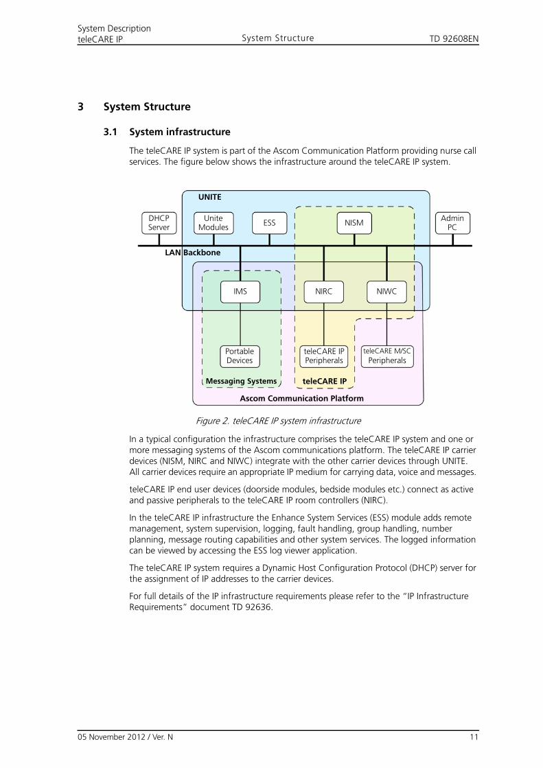
The teleCARE IP system is part of the Ascom Communication Platform providing nurse call services. The figure below shows the infrastructure around the teleCARE IP system.
Figure 2. teleCARE IP system infrastructure
In a typical configuration the infrastructure comprises the teleCARE IP system and one or more messaging systems of the Ascom communications platform. The teleCARE IP carrier devices (NISM, NIRC and NIWC) integrate with the other carrier devices through UNITE. All carrier devices require an appropriate IP medium for carrying data, voice and messages.
teleCARE IP end user devices (doorside modules, bedside modules etc.) connect as active and passive peripherals to the teleCARE IP room controllers (NIRC).
In the teleCARE IP infrastructure the Enhance System Services (ESS) module adds remote management, system supervision, logging, fault handling, group handling, number planning, message routing capabilities and other system services. The logged information can be viewed by accessing the ESS log viewer application.
The teleCARE IP system requires a Dynamic Host Configuration Protocol (DHCP) server for the assignment of IP addresses to the carrier devices.
For full details of the IP infrastructure requirements please refer to the “IP Infrastructure Requirements” document TD 92636.
AdminPC
UniteModules
PortableDevices
teleCARE IPPeripherals
teleCARE M/SC
Peripherals
ESS NISM
IMS NIRC NIWC
DHCPServer
LAN Backbone
Messaging Systems teleCARE IP
Ascom Communication Platform
UNITE
05 November 2012 / Ver. N 11
TD 92608ENSystem DescriptionteleCARE IP System Structure
3.1.1 IP Medium
teleCARE IP can use any IP medium. An IP medium could for example be a LAN network. The physical connection of NISM, NIRC and NIWC is Ethernet LAN using Cat-5 (or above) 10/100 Base-T or Unshielded Twisted Pair wiring (UTP).
Through WLAN Ethernet adapters teleCARE IP can integrate into a customer's wireless local area network (WLAN).
3.1.2 DHCP Server
The teleCARE IP network infrastructure requires a Dynamic Host Configuration Protocol (DHCP) server to operate in reservation mode. In DHCP reservation mode the DHCP server assigns to each IP client a permanent IP address.
3.1.3 UNITE
Ascom’s unified IP-based telecommunication environment (UNITE) serves to integrate the various systems of the Ascom communications platform. UNITE offers system level services such as nurse call, messaging, alarm handling, logging, fault handling, supervision, message routing, group handling, number planning, and other mission critical services.
3.1.4 Messaging Services
Messaging services can be provided to a teleCARE IP system by adding Ascom messaging systems such as IP-DECT, VoWiFi and System 900 to the system infrastructure. The NIRD Room Display serves as an Ascom interactive messaging device which can be included as part of any teleCARE IP system. The resulting integrated infrastructure provides the nurse call system with speech, interactive messaging and alarm services.
3.1.5 System Management
The teleCARE IP system is centrally managed by the teleCARE IP System Manager (NISM). This is an Elise module that contains the configurations of all teleCARE IP controllers that are part of the teleCARE IP system. The NISM contains a Java based client web application. The client web application is retrieved over the IP medium and runs inside a web browser.
3.1.6 Scalability
The scalability of teleCARE IP gives significant freedom when deciding the mix of system services. The options range from basic nurse call, with light guidance and call forwarding, up to hunting chain, nurse and staff assignment services.
3.1.7 Decentralised System Intelligence
The teleCARE IP system intelligence is decentralised and contained in teleCARE IP controllers that connect as autonomous nodes to the IP medium. Each teleCARE IP controller has an interface with UNITE. teleCARE IP controllers have a MAC and associated IP address giving them a unique identity at room level in the teleCARE IP system.
3.1.8 Fail Safe
In case of failure of the IP network the teleCARE IP controllers will continue locally controlling the connected peripherals. During an IP network failure all existing calls will continue to be locally registered and signalled. As soon as the IP network is available to the teleCARE IP controller again the decentrally stored calls will be fully restored.
05 November 2012 / Ver. N 12
TD 92608ENSystem DescriptionteleCARE IP System Structure
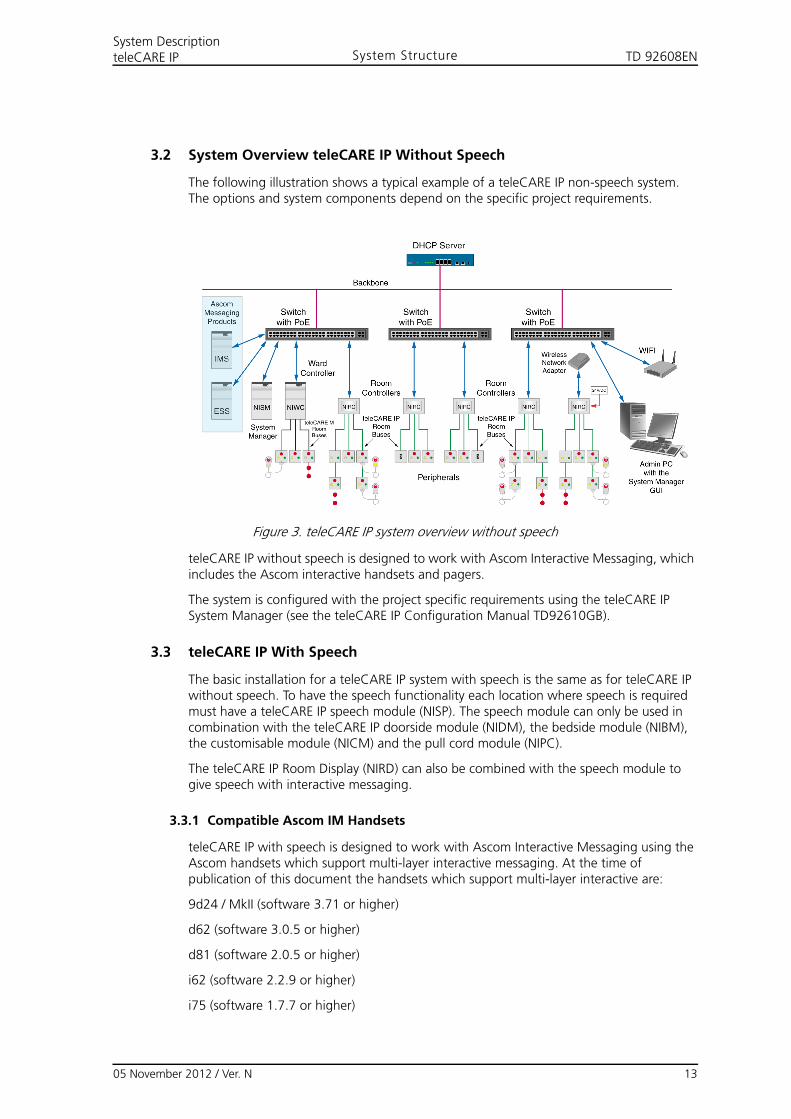
3.2 System Overview teleCARE IP Without Speech
The following illustration shows a typical example of a teleCARE IP non-speech system. The options and system components depend on the specific project requirements.
Figure 3. teleCARE IP system overview without speech
teleCARE IP without speech is designed to work with Ascom Interactive Messaging, which includes the Ascom interactive handsets and pagers.
The system is configured with the project specific requirements using the teleCARE IP System Manager (see the teleCARE IP Configuration Manual TD92610GB).
3.3 teleCARE IP With Speech
The basic installation for a teleCARE IP system with speech is the same as for teleCARE IP without speech. To have the speech functionality each location where speech is required must have a teleCARE IP speech module (NISP). The speech module can only be used in combination with the teleCARE IP doorside module (NIDM), the bedside module (NIBM), the customisable module (NICM) and the pull cord module (NIPC).
The teleCARE IP Room Display (NIRD) can also be combined with the speech module to give speech with interactive messaging.
3.3.1 Compatible Ascom IM Handsets
teleCARE IP with speech is designed to work with Ascom Interactive Messaging using the Ascom handsets which support multi-layer interactive messaging. At the time of publication of this document the handsets which support multi-layer interactive are:
9d24 / MkII (software 3.71 or higher)
d62 (software 3.0.5 or higher)
d81 (software 2.0.5 or higher)
i62 (software 2.2.9 or higher)
i75 (software 1.7.7 or higher)
05 November 2012 / Ver. N 13
TD 92608ENSystem DescriptionteleCARE IP System Structure
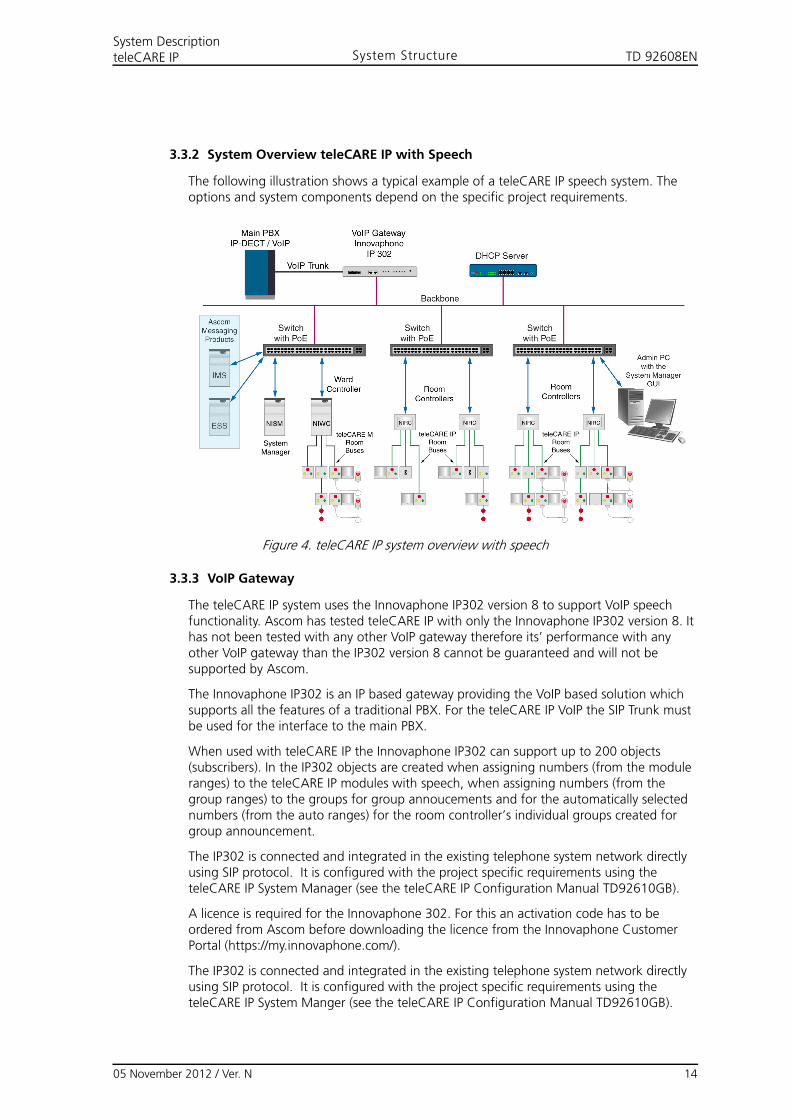
3.3.2 System Overview teleCARE IP with Speech
The following illustration shows a typical example of a teleCARE IP speech system. The options and system components depend on the specific project requirements.
Figure 4. teleCARE IP system overview with speech
3.3.3 VoIP Gateway
The teleCARE IP system uses the Innovaphone IP302 version 8 to support VoIP speech functionality. Ascom has tested teleCARE IP with only the Innovaphone IP302 version 8. It has not been tested with any other VoIP gateway therefore its’ performance with any other VoIP gateway than the IP302 version 8 cannot be guaranteed and will not be supported by Ascom.
The Innovaphone IP302 is an IP based gateway providing the VoIP based solution which supports all the features of a traditional PBX. For the teleCARE IP VoIP the SIP Trunk must be used for the interface to the main PBX.
When used with teleCARE IP the Innovaphone IP302 can support up to 200 objects (subscribers). In the IP302 objects are created when assigning numbers (from the module ranges) to the teleCARE IP modules with speech, when assigning numbers (from the group ranges) to the groups for group annoucements and for the automatically selected numbers (from the auto ranges) for the room controller’s individual groups created for group announcement.
The IP302 is connected and integrated in the existing telephone system network directly using SIP protocol. It is configured with the project specific requirements using the teleCARE IP System Manager (see the teleCARE IP Configuration Manual TD92610GB).
A licence is required for the Innovaphone 302. For this an activation code has to be ordered from Ascom before downloading the licence from the Innovaphone Customer Portal (https://my.innovaphone.com/).
The IP302 is connected and integrated in the existing telephone system network directly using SIP protocol. It is configured with the project specific requirements using the teleCARE IP System Manger (see the teleCARE IP Configuration Manual TD92610GB).
05 November 2012 / Ver. N 14
TD 92608ENSystem DescriptionteleCARE IP Power Supply
4 System Power Supply
The teleCARE IP system power supply can be sourced from either Power over Ethernet (PoE) or an external 24VDC power supply and a separate 2-wire power distribution bus.
4.1 Power over Ethernet (PoE)
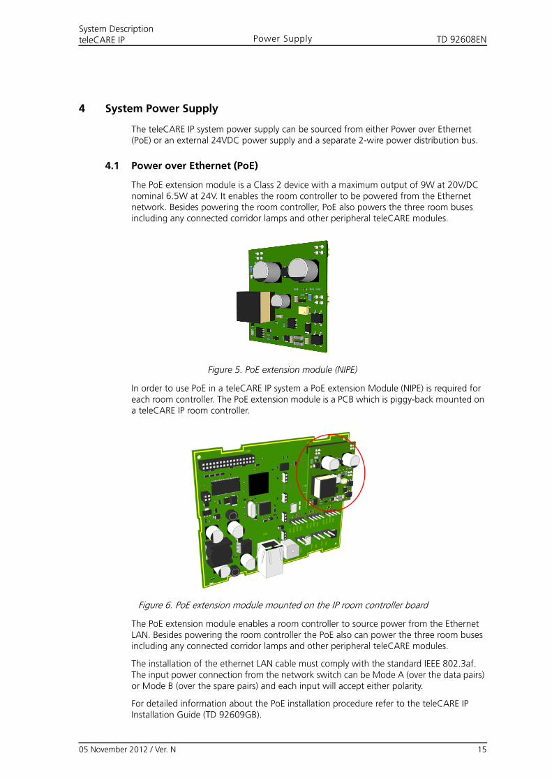
The PoE extension module is a Class 2 device with a maximum output of 9W at 20V/DC nominal 6.5W at 24V. It enables the room controller to be powered from the Ethernet network. Besides powering the room controller, PoE also powers the three room buses including any connected corridor lamps and other peripheral teleCARE modules.
Figure 5. PoE extension module (NIPE)
In order to use PoE in a teleCARE IP system a PoE extension Module (NIPE) is required for each room controller. The PoE extension module is a PCB which is piggy-back mounted on a teleCARE IP room controller.
Figure 6. PoE extension module mounted on the IP room controller board
The PoE extension module enables a room controller to source power from the Ethernet LAN. Besides powering the room controller the PoE also can power the three room buses including any connected corridor lamps and other peripheral teleCARE modules.
The installation of the ethernet LAN cable must comply with the standard IEEE 802.3af. The input power connection from the network switch can be Mode A (over the data pairs) or Mode B (over the spare pairs) and each input will accept either polarity.
For detailed information about the PoE installation procedure refer to the teleCARE IP Installation Guide (TD 92609GB).
05 November 2012 / Ver. N 15
TD 92608ENSystem DescriptionteleCARE IP Power Supply
4.2 External Power Supply
The Ascom 24V/DC power supply unit must be used for external power. The external power requirement for the teleCARE IP system is 24 volt DC. The acceptable range of the power supply voltage is 21.6V to 26.4V.
The Ascom 24V/DC power supply units are EN 60601-1-2 certified and “CE” marked. The input mains power requirement is 230V/50-60HZ.
The power supply unit must be plugged into an “Essential” power outlet.
Note: In VDE compliant installations the input power plug must not be used. The mains power leads should be screw-connected to the “Essential” mains power.
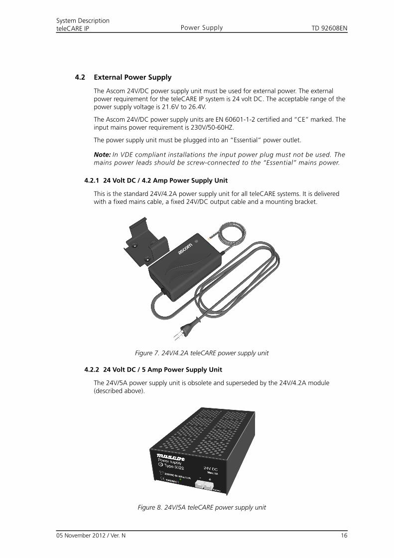
4.2.1 24 Volt DC / 4.2 Amp Power Supply Unit
This is the standard 24V/4.2A power supply unit for all teleCARE systems. It is delivered with a fixed mains cable, a fixed 24V/DC output cable and a mounting bracket.
Figure 7. 24V/4.2A teleCARE power supply unit
4.2.2 24 Volt DC / 5 Amp Power Supply Unit
The 24V/5A power supply unit is obsolete and superseded by the 24V/4.2A module (described above).
Figure 8. 24V/5A teleCARE power supply unit
05 November 2012 / Ver. N 16
TD 92608ENSystem DescriptionteleCARE IP Control Equipment
5 Control Equipment
This section describes the installation instructions for the following products:
• “Room Controller” (details on page 17)
• “Blank Front Cover for the Room Controller” (details on page 19)
• “Power over Ethernet Extension Module” (details on page 19)
• “Slave Corridor Lamp” (details on page 20)
• “System Manager (NISM)” (details on page 23)
• “System Manager (NISM2)” (details on page 25)
• “Ward Controller” (details on page 27)
• “Voice Module” (details on page 28)
5.1 Room Controller
The Room Controller (NIRC) is available in grey or white and it has a translucent dome cover which accepts up to four LED boards which must be ordered separately. The LEDs are used for the signalling of calls, nurse presence and faults. The LED board is available in five colours: red, green, yellow, white and blue (see “LED Lamps” on page 21).
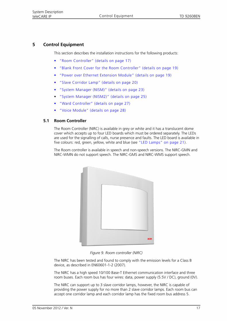
The Room controller is available in speech and non-speech versions. The NIRC-GMN and NIRC-WMN do not support speech. The NIRC-GMS and NIRC-WMS support speech.
Figure 9. Room controller (NIRC)
The NIRC has been tested and found to comply with the emission levels for a Class B device, as described in EN60601-1-2 (2007).
The NIRC has a high speed 10/100 Base-T Ethernet communication interface and three room buses. Each room bus has four wires: data, power supply (5.5V / DC), ground (0V).
The NIRC can support up to 3 slave corridor lamps, however, the NIRC is capable of providing the power supply for no more than 2 slave corridor lamps. Each room bus can accept one corridor lamp and each corridor lamp has the fixed room bus address 5.
05 November 2012 / Ver. N 17
TD 92608ENSystem DescriptionteleCARE IP Control Equipment
The NIRC has a 6-pole output connection for 4 external corridor LEDs. These outputs are in parallel to the NIRC’s on-board LED connectors. Additionally, the NIRC has an internal buzzer for optional audible signalling of calls and faults.
Each room bus of the NIRC supports eight addresses. The room bus address applications are summarized in the following table:
Table 1. Room bus addresses and applications
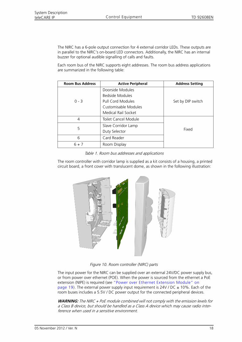
The room controller with corridor lamp is supplied as a kit consists of a housing, a printed circuit board, a front cover with translucent dome, as shown in the following illustration:
Figure 10. Room controller (NIRC) parts
The input power for the NIRC can be supplied over an external 24V/DC power supply bus, or from power over ethernet (POE). When the power is sourced from the ethernet a PoE extension (NIPE) is required (see “Power over Ethernet Extension Module” on page 19). The external power supply input requirement is 24V / DC ± 10%. Each of the room buses includes a 5.5V / DC power output for the connected peripheral devices.
WARNING: The NIRC + PoE module combined will not comply with the emission levels for a Class B device, but should be handled as a Class A device which may cause radio inter-ference when used in a sensitive environment.
Room Bus Address Active Peripheral Address Setting
0 - 3
Doorside Modules
Bedside Modules
Pull Cord Modules
Customisable Modules
Medical Rail Socket
Set by DIP switch
4 Toilet Cancel Module
Fixed5Slave Corridor Lamp
Duty Selector
6 Card Reader
6 + 7 Room Display
05 November 2012 / Ver. N 18
TD 92608ENSystem DescriptionteleCARE IP Control Equipment
5.2 Blank Front Cover for the Room Controller
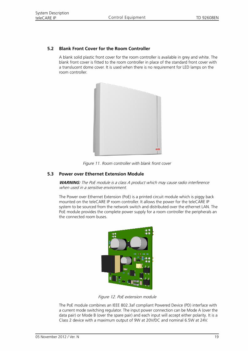
A blank solid plastic front cover for the room controller is available in grey and white. The blank front cover is fitted to the room controller in place of the standard front cover with a translucent dome cover. It is used when there is no requirement for LED lamps on the room controller.
Figure 11. Room controller with blank front cover
5.3 Power over Ethernet Extension Module
WARNING: The PoE module is a class A product which may cause radio interference when used in a sensitive environment.
The Power over Ethernet Extension (PoE) is a printed circuit module which is piggy back mounted on the teleCARE IP room controller. It allows the power for the teleCARE IP system to be sourced from the network switch and distributed over the ethernet LAN. The PoE module provides the complete power supply for a room controller the peripherals an the connected room buses.
Figure 12. PoE extension module
The PoE module combines an IEEE 802.3af compliant Powered Device (PD) interface with a current mode switching regulator. The input power connection can be Mode A (over the data pair) or Mode B (over the spare pair) and each input will accept either polarity. It is a Class 2 device with a maximum output of 9W at 20V/DC and nominal 6.5W at 24V.
05 November 2012 / Ver. N 19
TD 92608ENSystem DescriptionteleCARE IP Control Equipment
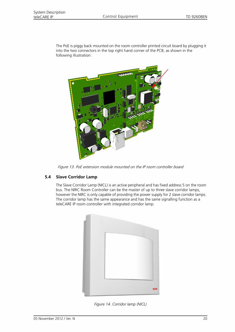
The PoE is piggy back mounted on the room controller printed circuit board by plugging it into the two connectors in the top right hand corner of the PCB, as shown in the following illustration:
Figure 13. PoE extension module mounted on the IP room controller board
5.4 Slave Corridor Lamp
The Slave Corridor Lamp (NICL) is an active peripheral and has fixed address 5 on the room bus. The NIRC Room Controller can be the master of up to three slave corridor lamps, however the NIRC is only capable of providing the power supply for 2 slave corridor lamps. The corridor lamp has the same appearance and has the same signalling function as a teleCARE IP room controller with integrated corridor lamp.
Figure 14. Corridor lamp (NICL)
05 November 2012 / Ver. N 20
TD 92608ENSystem DescriptionteleCARE IP Control Equipment
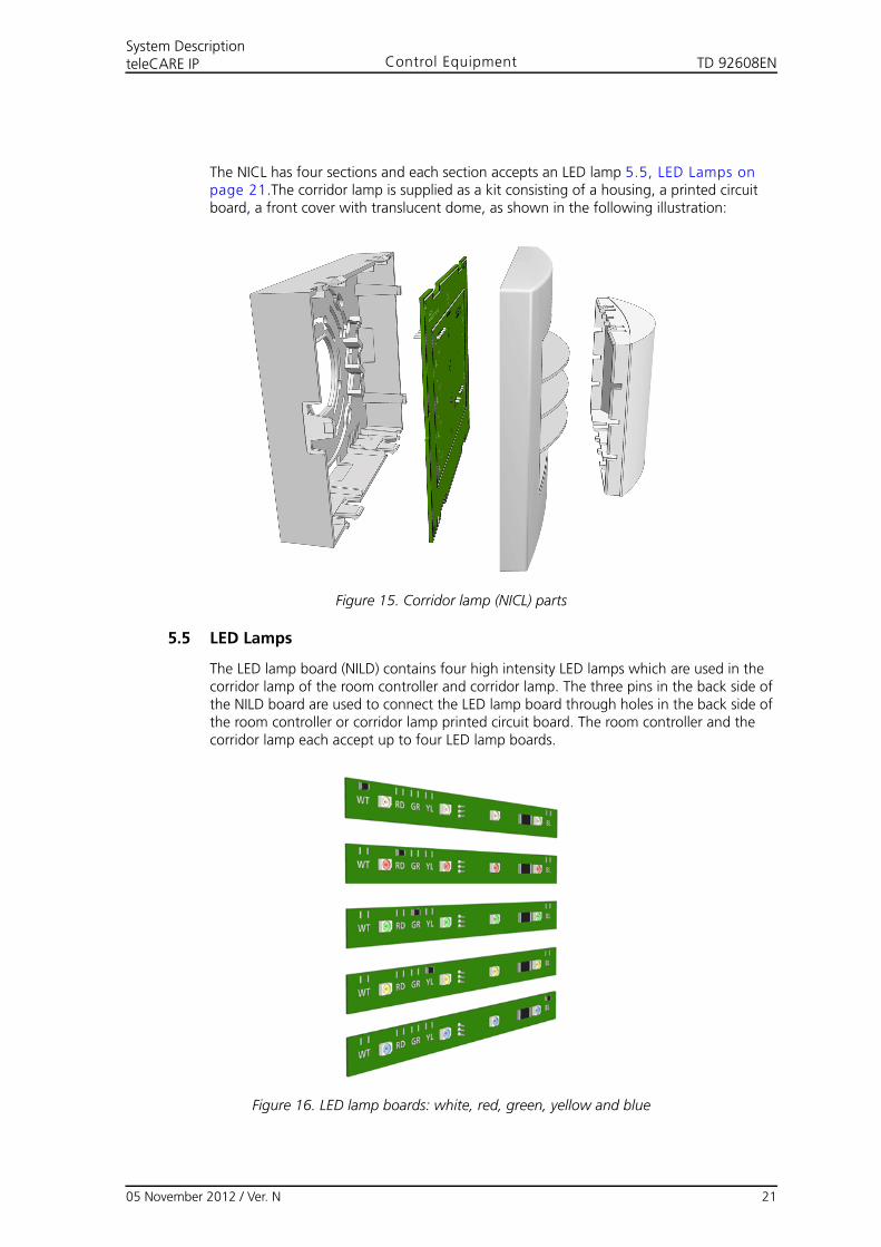
The NICL has four sections and each section accepts an LED lamp 5.5, LED Lamps on page 21.The corridor lamp is supplied as a kit consisting of a housing, a printed circuit board, a front cover with translucent dome, as shown in the following illustration:
Figure 15. Corridor lamp (NICL) parts
5.5 LED Lamps
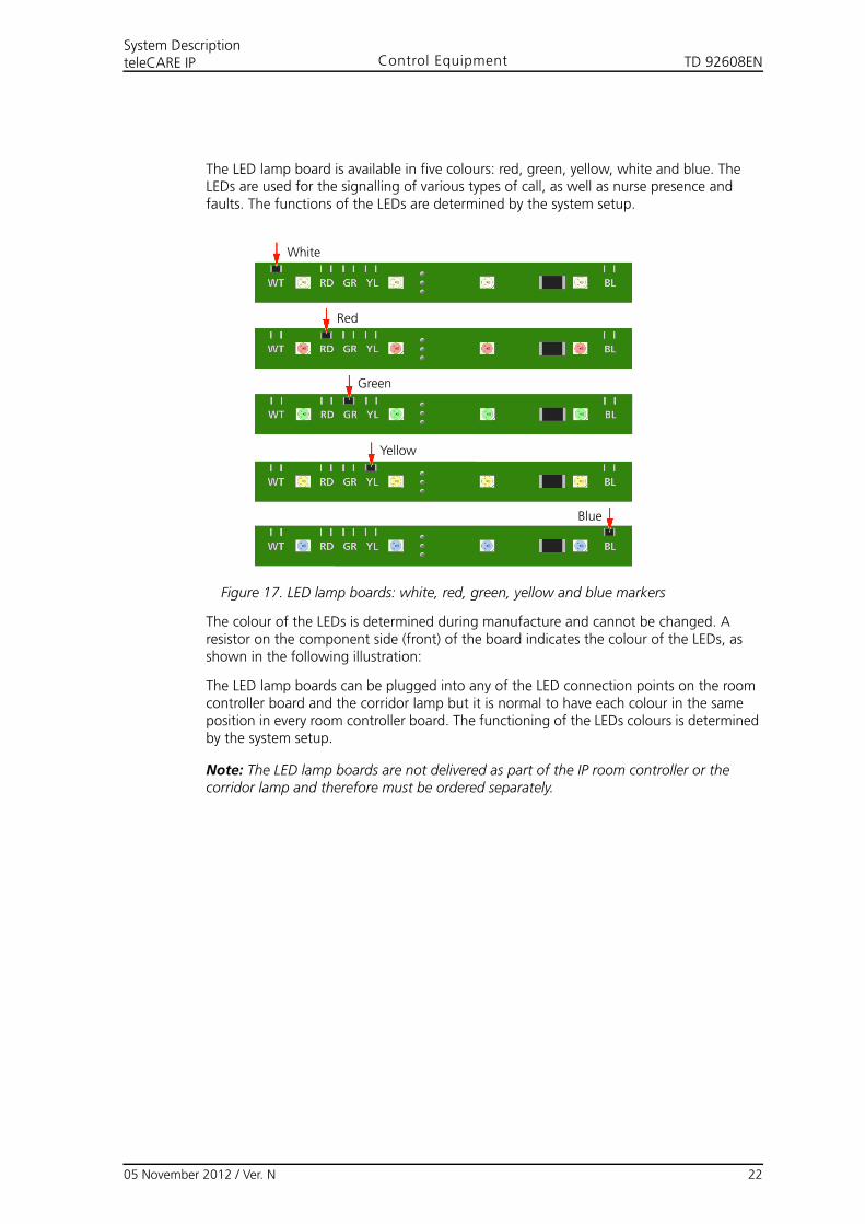
The LED lamp board (NILD) contains four high intensity LED lamps which are used in the corridor lamp of the room controller and corridor lamp. The three pins in the back side of the NILD board are used to connect the LED lamp board through holes in the back side of the room controller or corridor lamp printed circuit board. The room controller and the corridor lamp each accept up to four LED lamp boards.
Figure 16. LED lamp boards: white, red, green, yellow and blue
05 November 2012 / Ver. N 21
TD 92608ENSystem DescriptionteleCARE IP Control Equipment
The LED lamp board is available in five colours: red, green, yellow, white and blue. The LEDs are used for the signalling of various types of call, as well as nurse presence and faults. The functions of the LEDs are determined by the system setup.
Figure 17. LED lamp boards: white, red, green, yellow and blue markers
The colour of the LEDs is determined during manufacture and cannot be changed. A resistor on the component side (front) of the board indicates the colour of the LEDs, as shown in the following illustration:
The LED lamp boards can be plugged into any of the LED connection points on the room controller board and the corridor lamp but it is normal to have each colour in the same position in every room controller board. The functioning of the LEDs colours is determined by the system setup.
Note: The LED lamp boards are not delivered as part of the IP room controller or the corridor lamp and therefore must be ordered separately.
White
Red
Green
Yellow
Blue
05 November 2012 / Ver. N 22

TD 92608ENSystem DescriptionteleCARE IP Control Equipment
5.6 System Manager (NISM)
The teleCARE IP System Manager (NISM) is an Ascom ELISE application built on the ELISE2 module.
The NISM is the tool for centrally managing the teleCARE IP system through a graphical user interface (GUI). It is used to configure, install, maintain and monitor the system.
Figure 18. teleCARE IP System Manager (NISM)
The NISM contains a Linux based web server which functions as the interface to a 100BASE-T Ethernet LAN. The NISM contains a client web application which enables the NISM to be managed from a (remote) client.
The NISM is connected to the IP network and stores the configurations for each of the teleCARE IP Room Controllers and Ward Controllers that are connected to the IP network. The data stored by the NISM can be retrieved over the IP medium and run inside a web browser on a remote client.
Note: The NISM power requirement is 12V/DC to 24V/DC, therefore it can be used with the Ascom power supply (12.5V/DC) or the teleCARE IP power supply (24V/DC).
05 November 2012 / Ver. N 23
TD 92608ENSystem DescriptionteleCARE IP Control Equipment
5.6.1 NISM Graphical User Interface (GUI)
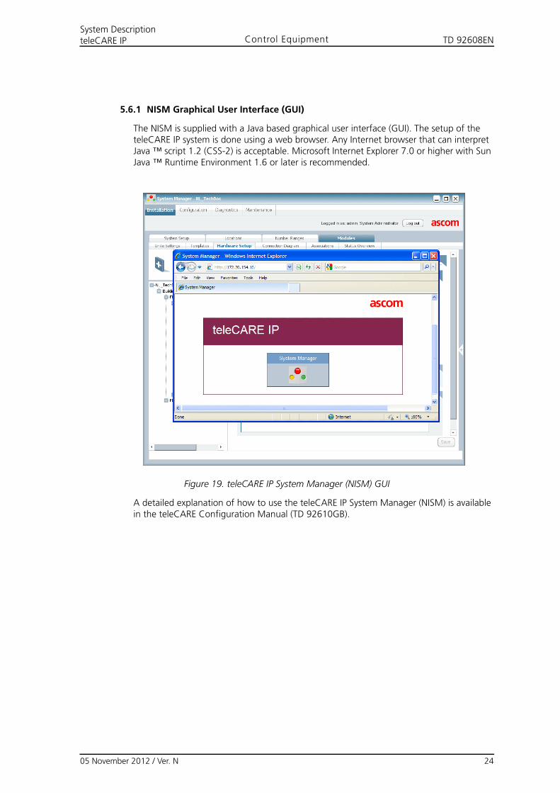
The NISM is supplied with a Java based graphical user interface (GUI). The setup of the teleCARE IP system is done using a web browser. Any Internet browser that can interpret Java ™ script 1.2 (CSS-2) is acceptable. Microsoft Internet Explorer 7.0 or higher with Sun Java ™ Runtime Environment 1.6 or later is recommended.
Figure 19. teleCARE IP System Manager (NISM) GUI
A detailed explanation of how to use the teleCARE IP System Manager (NISM) is available in the teleCARE Configuration Manual (TD 92610GB).
05 November 2012 / Ver. N 24
TD 92608ENSystem DescriptionteleCARE IP Control Equipment
5.7 System Manager (NISM2)
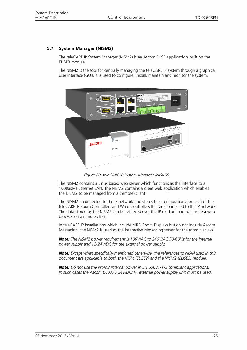
The teleCARE IP System Manager (NISM2) is an Ascom ELISE application built on the ELISE3 module.
The NISM2 is the tool for centrally managing the teleCARE IP system through a graphical user interface (GUI). It is used to configure, install, maintain and monitor the system.
Figure 20. teleCARE IP System Manager (NISM2)
The NISM2 contains a Linux based web server which functions as the interface to a 100Base-T Ethernet LAN. The NISM2 contains a client web application which enables the NISM2 to be managed from a (remote) client.
The NISM2 is connected to the IP network and stores the configurations for each of the teleCARE IP Room Controllers and Ward Controllers that are connected to the IP network. The data stored by the NISM2 can be retrieved over the IP medium and run inside a web browser on a remote client.
In teleCARE IP installations which include NIRD Room Displays but do not include Ascom Messaging, the NISM2 is used as the Interactive Messaging server for the room displays.
Note: The NISM2 power requirement is 100V/AC to 240V/AC 50-60Hz for the internal power supply and 12-24V/DC for the external power supply.
Note: Except when specifically mentioned otherwise, the references to NISM used in this document are applicable to both the NISM (ELISE2) and the NISM2 (ELISE3) module.
Note: Do not use the NISM2 internal power in EN 60601-1-2 compliant applications.In such cases the Ascom 660376 24V/DC/4A external power supply unit must be used.
05 November 2012 / Ver. N 25
TD 92608ENSystem DescriptionteleCARE IP Control Equipment
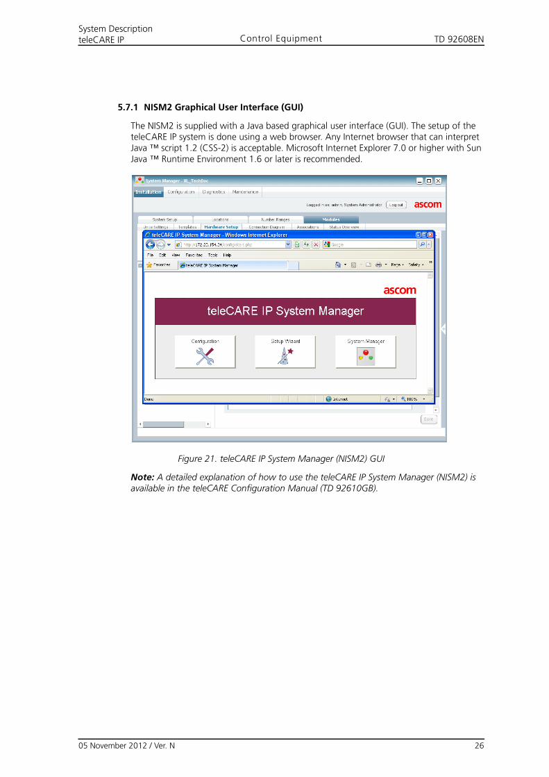
5.7.1 NISM2 Graphical User Interface (GUI)
The NISM2 is supplied with a Java based graphical user interface (GUI). The setup of the teleCARE IP system is done using a web browser. Any Internet browser that can interpret Java ™ script 1.2 (CSS-2) is acceptable. Microsoft Internet Explorer 7.0 or higher with Sun Java ™ Runtime Environment 1.6 or later is recommended.
Figure 21. teleCARE IP System Manager (NISM2) GUI
Note: A detailed explanation of how to use the teleCARE IP System Manager (NISM2) is available in the teleCARE Configuration Manual (TD 92610GB).
05 November 2012 / Ver. N 26
TD 92608ENSystem DescriptionteleCARE IP Control Equipment
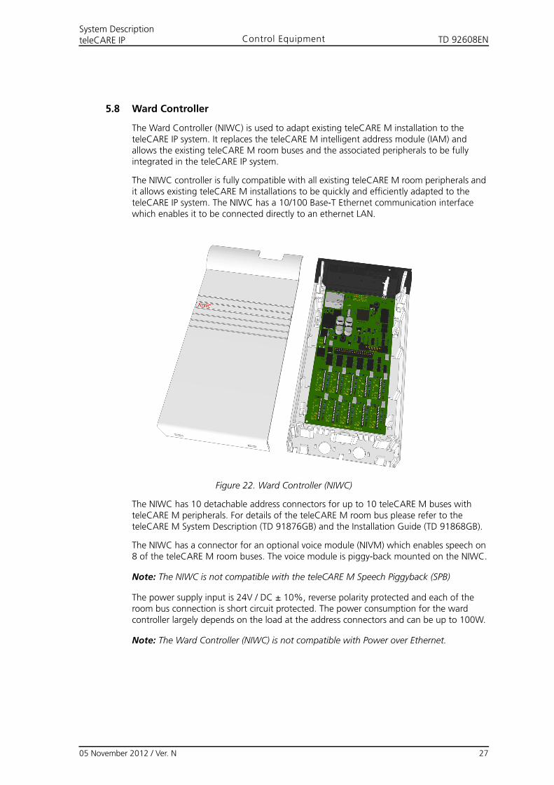
5.8 Ward Controller
The Ward Controller (NIWC) is used to adapt existing teleCARE M installation to the teleCARE IP system. It replaces the teleCARE M intelligent address module (IAM) and allows the existing teleCARE M room buses and the associated peripherals to be fully integrated in the teleCARE IP system.
The NIWC controller is fully compatible with all existing teleCARE M room peripherals and it allows existing teleCARE M installations to be quickly and efficiently adapted to the teleCARE IP system. The NIWC has a 10/100 Base-T Ethernet communication interface which enables it to be connected directly to an ethernet LAN.
Figure 22. Ward Controller (NIWC)
The NIWC has 10 detachable address connectors for up to 10 teleCARE M buses with teleCARE M peripherals. For details of the teleCARE M room bus please refer to the teleCARE M System Description (TD 91876GB) and the Installation Guide (TD 91868GB).
The NIWC has a connector for an optional voice module (NIVM) which enables speech on 8 of the teleCARE M room buses. The voice module is piggy-back mounted on the NIWC.
Note: The NIWC is not compatible with the teleCARE M Speech Piggyback (SPB)
The power supply input is 24V / DC ± 10%, reverse polarity protected and each of the room bus connection is short circuit protected. The power consumption for the ward controller largely depends on the load at the address connectors and can be up to 100W.
Note: The Ward Controller (NIWC) is not compatible with Power over Ethernet.
05 November 2012 / Ver. N 27
TD 92608ENSystem DescriptionteleCARE IP Control Equipment
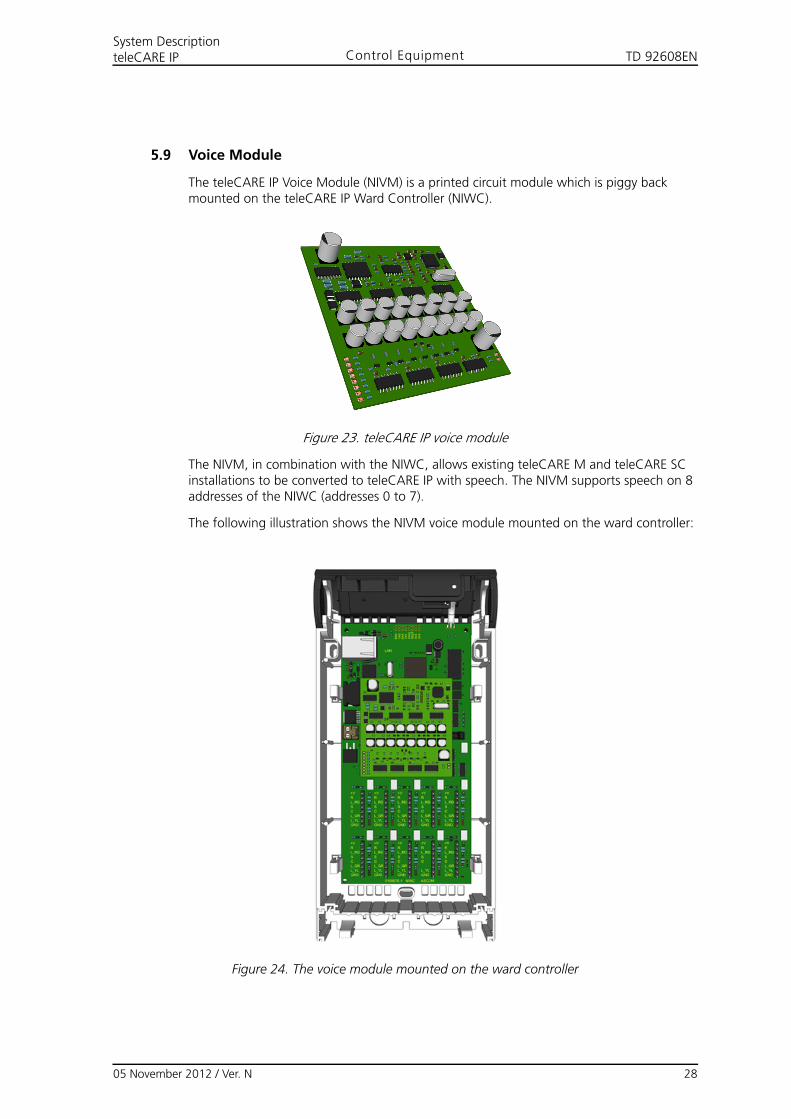
5.9 Voice Module
The teleCARE IP Voice Module (NIVM) is a printed circuit module which is piggy back mounted on the teleCARE IP Ward Controller (NIWC).
Figure 23. teleCARE IP voice module
The NIVM, in combination with the NIWC, allows existing teleCARE M and teleCARE SC installations to be converted to teleCARE IP with speech. The NIVM supports speech on 8 addresses of the NIWC (addresses 0 to 7).
The following illustration shows the NIVM voice module mounted on the ward controller:
Figure 24. The voice module mounted on the ward controller
05 November 2012 / Ver. N 28
TD 92608ENSystem DescriptionteleCARE IP Control Equipment
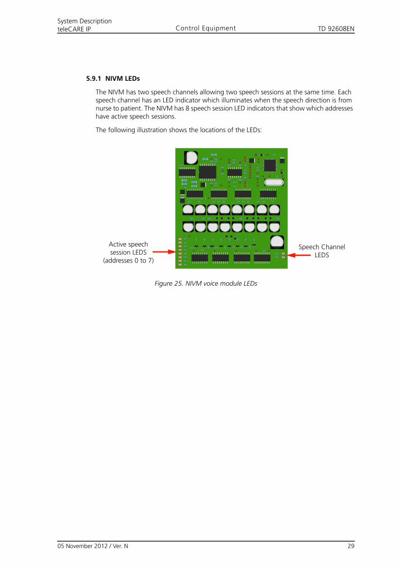
5.9.1 NIVM LEDs
The NIVM has two speech channels allowing two speech sessions at the same time. Each speech channel has an LED indicator which illuminates when the speech direction is from nurse to patient. The NIVM has 8 speech session LED indicators that show which addresses have active speech sessions.
The following illustration shows the locations of the LEDs:
Figure 25. NIVM voice module LEDs
Active speech session LEDS
(addresses 0 to 7)
Speech Channel LEDS
05 November 2012 / Ver. N 29
TD 92608ENSystem DescriptionteleCARE IP Peripherals
6 Peripherals
6.1 General
A peripheral is an end user device that can be part of teleCARE IP System. This section describes the following peripheral devices:
• “Bedside Module (NIBM2)” (details on page 32)
• “Bedside Module (NIBM)” (details on page 33)
• “Socket Extension Module (NISE)” (details on page 33)
• “Doorside Module (NIDM)” (details on page 34)
• “Pull Cord Module (NIPC)” (details on page 34)
• “Toilet Cancel Module (NITC)” (details on page 35)
• “Pull Cord Module - Passive (NIPC)” (details on page 35)
• “Toilet Cancel Module - Passive (NITC)” (details on page 36)
• “Wet Area Cover (WAC)” (details on page 36)
• “Pull Cord Module - IP44 (NIPC2)” (details on page 37)
• “Medical Rail Module (NIMS2)” (details on page 38)
• “Medical Rail Module (NIMS)” (details on page 39)
• “Customisable Module NICM-A3A and NICM-A1A” (details on page 40)
• “Duty Selector (NIDS)” (details on page 42)
• “Card Reader Module (NICR)” (details on page 43)
• “Speech Module (NISP)” (details on page 44)
• “Acoustic Monitoring” (details on page 45)
• “Room Display (NIRD)” (details on page 46)
• “Television Interface Module” (details on page 49)
• “Sunblind Control Module” (details on page 50)
• “Multi Medical Alarm Module (NIMA)” (details on page 51)
• “Multi General Alarm Module (NIGA)” (details on page 53)
6.2 Switch Modules
The teleCARE IP switch modules are available as active and passive peripherals.
Switch modules are available in a three button, two button, one button, or blank layout. The button colours of a three button switch module are red, yellow and green. The button colours of a two button switch module are yellow and green. The button colour of a one button switch module is red. A blank module has no buttons. All the buttons are assigned a reassurance LED which permanently emits a low intensity light for night-time locating and identification in the dark.
The function of the buttons on a teleCARE IP switch module is freely programmable using the teleCARE IP system manager. However, in a typical installation the red, green and yellow buttons are respectively used for making nurse calls, reporting nurse presence and calling for assistance.
05 November 2012 / Ver. N 30
TD 92608ENSystem DescriptionteleCARE IP Peripherals
Note: For cleaning instructions, see Appendix C: Cleaning the Switch Modules, on page 71.
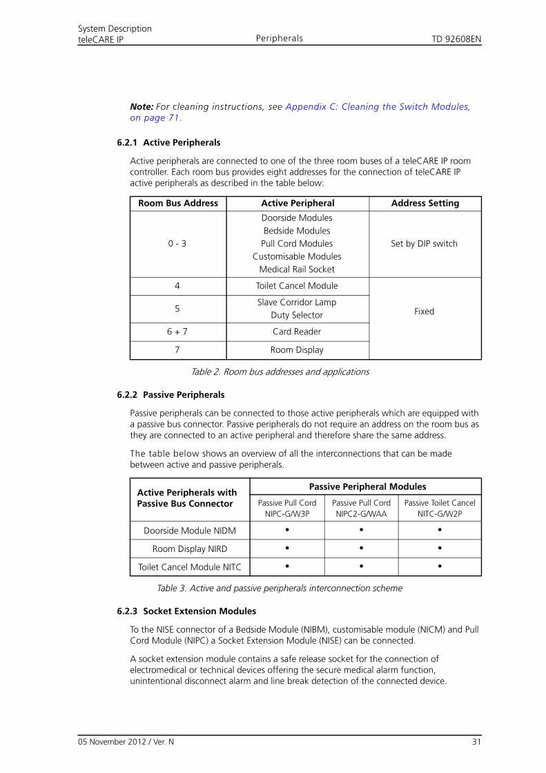
6.2.1 Active Peripherals
Active peripherals are connected to one of the three room buses of a teleCARE IP room controller. Each room bus provides eight addresses for the connection of teleCARE IP active peripherals as described in the table below:
Table 2. Room bus addresses and applications
6.2.2 Passive Peripherals
Passive peripherals can be connected to those active peripherals which are equipped with a passive bus connector. Passive peripherals do not require an address on the room bus as they are connected to an active peripheral and therefore share the same address.
The table below shows an overview of all the interconnections that can be made between active and passive peripherals.
Table 3. Active and passive peripherals interconnection scheme
6.2.3 Socket Extension Modules
To the NISE connector of a Bedside Module (NIBM), customisable module (NICM) and Pull Cord Module (NIPC) a Socket Extension Module (NISE) can be connected.
A socket extension module contains a safe release socket for the connection of electromedical or technical devices offering the secure medical alarm function, unintentional disconnect alarm and line break detection of the connected device.
Room Bus Address Active Peripheral Address Setting
0 - 3
Doorside Modules
Bedside Modules
Pull Cord Modules
Customisable Modules
Medical Rail Socket
Set by DIP switch
4 Toilet Cancel Module
Fixed5Slave Corridor Lamp
Duty Selector
6 + 7 Card Reader
7 Room Display
Active Peripherals with Passive Bus Connector
Passive Peripheral Modules
Passive Pull Cord
NIPC-G/W3P
Passive Pull Cord
NIPC2-G/WAA
Passive Toilet Cancel
NITC-G/W2P
Doorside Module NIDM • • •
Room Display NIRD • • •
Toilet Cancel Module NITC • • •
05 November 2012 / Ver. N 31
TD 92608ENSystem DescriptionteleCARE IP Peripherals
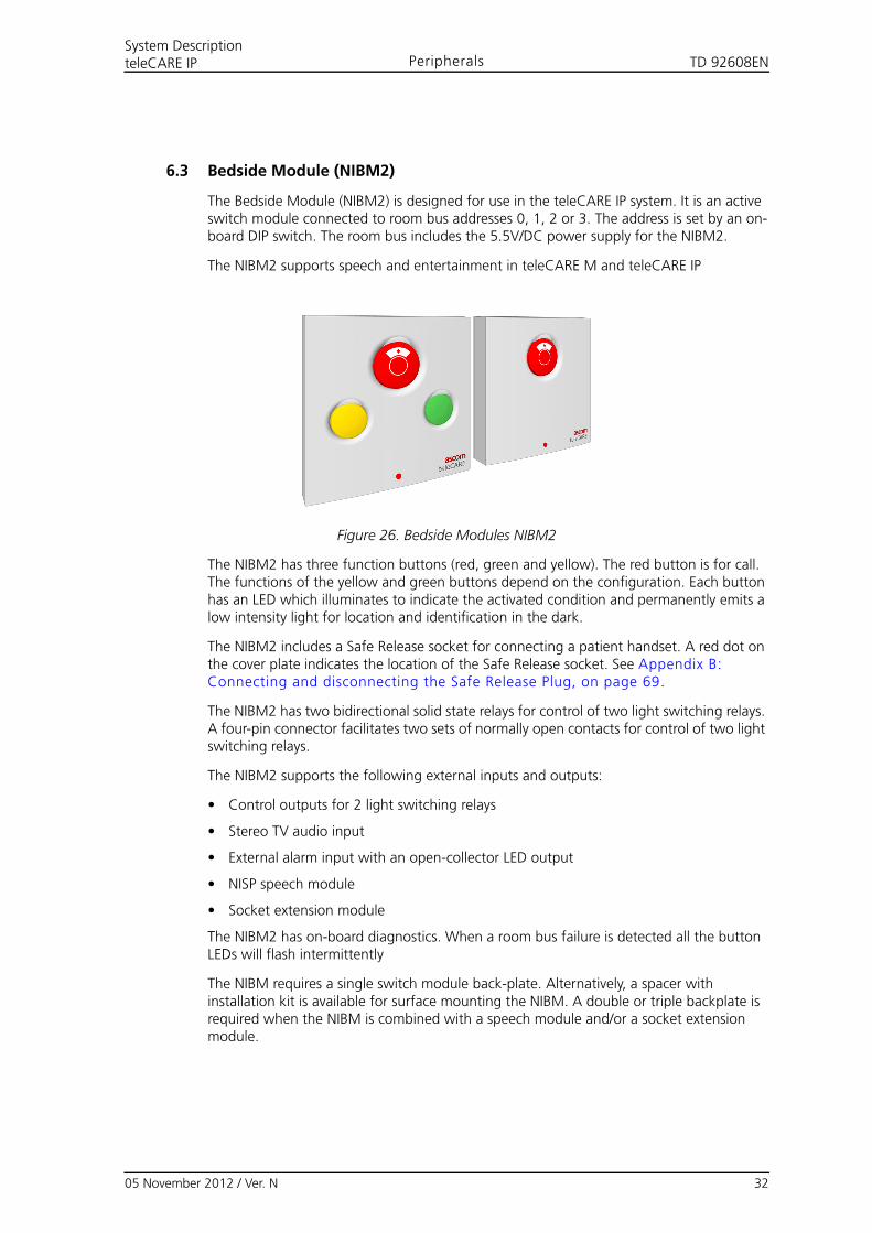
6.3 Bedside Module (NIBM2)
The Bedside Module (NIBM2) is designed for use in the teleCARE IP system. It is an active switch module connected to room bus addresses 0, 1, 2 or 3. The address is set by an on-board DIP switch. The room bus includes the 5.5V/DC power supply for the NIBM2.
The NIBM2 supports speech and entertainment in teleCARE M and teleCARE IP
Figure 26. Bedside Modules NIBM2
The NIBM2 has three function buttons (red, green and yellow). The red button is for call. The functions of the yellow and green buttons depend on the configuration. Each button has an LED which illuminates to indicate the activated condition and permanently emits a low intensity light for location and identification in the dark.
The NIBM2 includes a Safe Release socket for connecting a patient handset. A red dot on the cover plate indicates the location of the Safe Release socket. See Appendix B: Connecting and disconnecting the Safe Release Plug, on page 69.
The NIBM2 has two bidirectional solid state relays for control of two light switching relays. A four-pin connector facilitates two sets of normally open contacts for control of two light switching relays.
The NIBM2 supports the following external inputs and outputs:
• Control outputs for 2 light switching relays
• Stereo TV audio input
• External alarm input with an open-collector LED output
• NISP speech module
• Socket extension module
The NIBM2 has on-board diagnostics. When a room bus failure is detected all the button LEDs will flash intermittently
The NIBM requires a single switch module back-plate. Alternatively, a spacer with installation kit is available for surface mounting the NIBM. A double or triple backplate is required when the NIBM is combined with a speech module and/or a socket extension module.
05 November 2012 / Ver. N 32
TD 92608ENSystem DescriptionteleCARE IP Peripherals
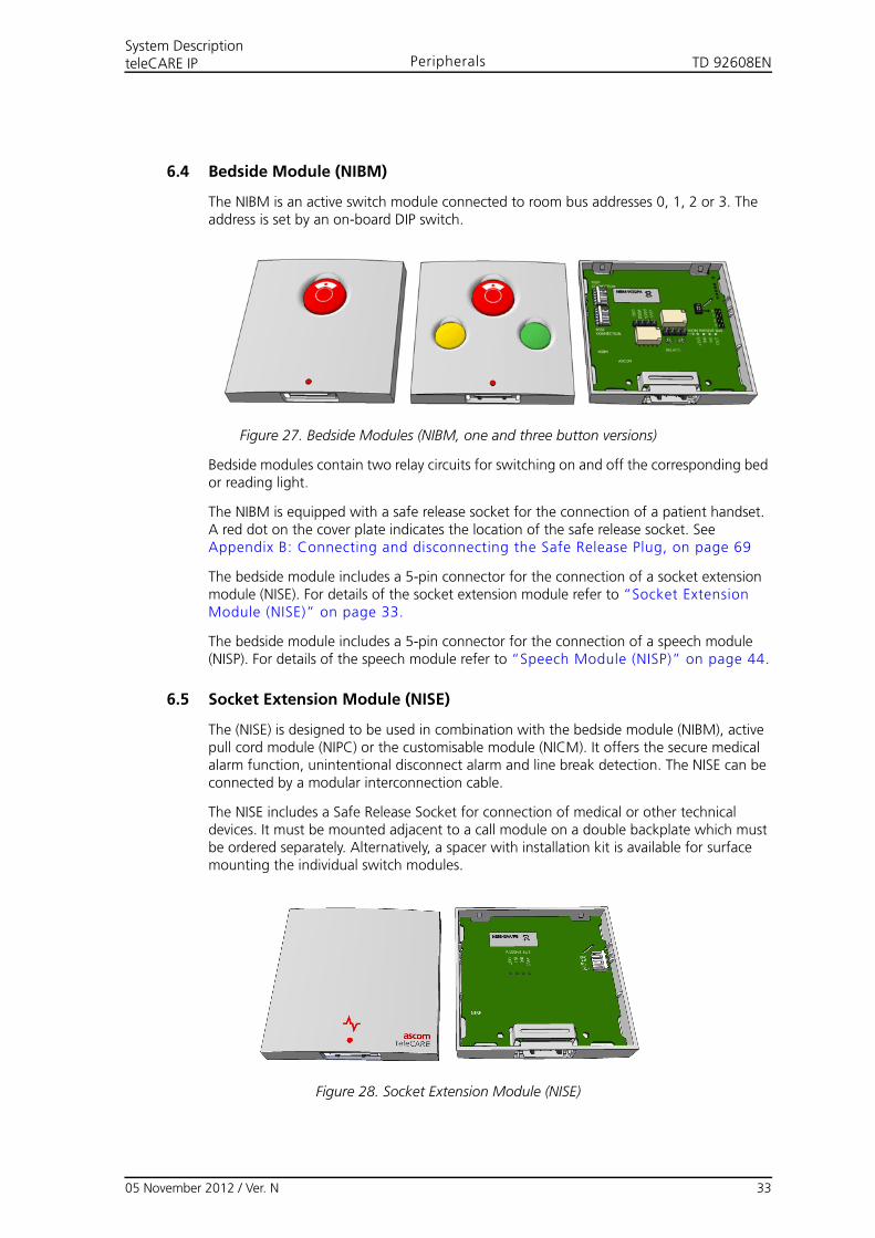
6.4 Bedside Module (NIBM)
The NIBM is an active switch module connected to room bus addresses 0, 1, 2 or 3. The address is set by an on-board DIP switch.
Figure 27. Bedside Modules (NIBM, one and three button versions)
Bedside modules contain two relay circuits for switching on and off the corresponding bed or reading light.
The NIBM is equipped with a safe release socket for the connection of a patient handset. A red dot on the cover plate indicates the location of the safe release socket. See Appendix B: Connecting and disconnecting the Safe Release Plug, on page 69
The bedside module includes a 5-pin connector for the connection of a socket extension module (NISE). For details of the socket extension module refer to “Socket Extension Module (NISE)” on page 33.
The bedside module includes a 5-pin connector for the connection of a speech module (NISP). For details of the speech module refer to “Speech Module (NISP)” on page 44.
6.5 Socket Extension Module (NISE)
The (NISE) is designed to be used in combination with the bedside module (NIBM), active pull cord module (NIPC) or the customisable module (NICM). It offers the secure medical alarm function, unintentional disconnect alarm and line break detection. The NISE can be connected by a modular interconnection cable.
The NISE includes a Safe Release Socket for connection of medical or other technical devices. It must be mounted adjacent to a call module on a double backplate which must be ordered separately. Alternatively, a spacer with installation kit is available for surface mounting the individual switch modules.
Figure 28. Socket Extension Module (NISE)
05 November 2012 / Ver. N 33
TD 92608ENSystem DescriptionteleCARE IP Peripherals
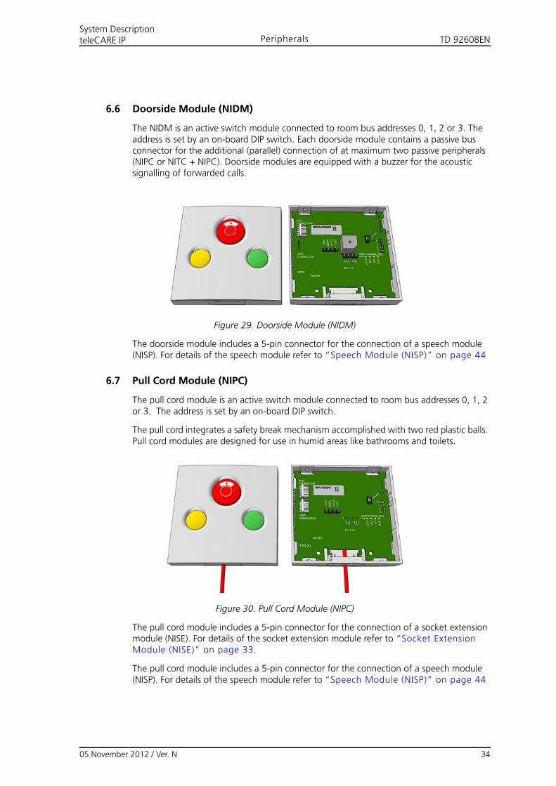
6.6 Doorside Module (NIDM)
The NIDM is an active switch module connected to room bus addresses 0, 1, 2 or 3. The address is set by an on-board DIP switch. Each doorside module contains a passive bus connector for the additional (parallel) connection of at maximum two passive peripherals (NIPC or NITC + NIPC). Doorside modules are equipped with a buzzer for the acoustic signalling of forwarded calls.
Figure 29. Doorside Module (NIDM)
The doorside module includes a 5-pin connector for the connection of a speech module (NISP). For details of the speech module refer to “Speech Module (NISP)” on page 44
6.7 Pull Cord Module (NIPC)
The pull cord module is an active switch module connected to room bus addresses 0, 1, 2 or 3. The address is set by an on-board DIP switch.
The pull cord integrates a safety break mechanism accomplished with two red plastic balls. Pull cord modules are designed for use in humid areas like bathrooms and toilets.
Figure 30. Pull Cord Module (NIPC)
The pull cord module includes a 5-pin connector for the connection of a socket extension module (NISE). For details of the socket extension module refer to “Socket Extension Module (NISE)” on page 33.
The pull cord module includes a 5-pin connector for the connection of a speech module (NISP). For details of the speech module refer to “Speech Module (NISP)” on page 44
05 November 2012 / Ver. N 34
TD 92608ENSystem DescriptionteleCARE IP Peripherals
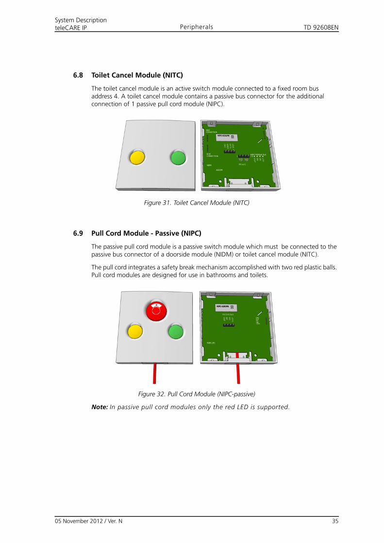
6.8 Toilet Cancel Module (NITC)
The toilet cancel module is an active switch module connected to a fixed room bus address 4. A toilet cancel module contains a passive bus connector for the additional connection of 1 passive pull cord module (NIPC).
Figure 31. Toilet Cancel Module (NITC)
6.9 Pull Cord Module - Passive (NIPC)
The passive pull cord module is a passive switch module which must be connected to the passive bus connector of a doorside module (NIDM) or toilet cancel module (NITC).
The pull cord integrates a safety break mechanism accomplished with two red plastic balls. Pull cord modules are designed for use in bathrooms and toilets.
Figure 32. Pull Cord Module (NIPC-passive)
Note: In passive pull cord modules only the red LED is supported.
05 November 2012 / Ver. N 35
TD 92608ENSystem DescriptionteleCARE IP Peripherals
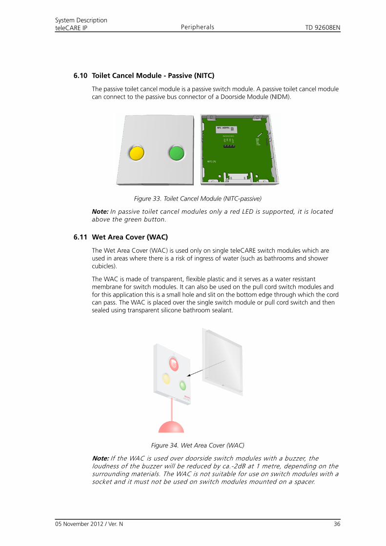
6.10 Toilet Cancel Module - Passive (NITC)
The passive toilet cancel module is a passive switch module. A passive toilet cancel module can connect to the passive bus connector of a Doorside Module (NIDM).
Figure 33. Toilet Cancel Module (NITC-passive)
Note: In passive toilet cancel modules only a red LED is supported, it is located above the green button.
6.11 Wet Area Cover (WAC)
The Wet Area Cover (WAC) is used only on single teleCARE switch modules which are used in areas where there is a risk of ingress of water (such as bathrooms and shower cubicles).
The WAC is made of transparent, flexible plastic and it serves as a water resistant membrane for switch modules. It can also be used on the pull cord switch modules and for this application this is a small hole and slit on the bottom edge through which the cord can pass. The WAC is placed over the single switch module or pull cord switch and then sealed using transparent silicone bathroom sealant.
Figure 34. Wet Area Cover (WAC)
Note: If the WAC is used over doorside switch modules with a buzzer, the loudness of the buzzer will be reduced by ca.-2dB at 1 metre, depending on the surrounding materials. The WAC is not suitable for use on switch modules with a socket and it must not be used on switch modules mounted on a spacer.
05 November 2012 / Ver. N 36
TD 92608ENSystem DescriptionteleCARE IP Peripherals
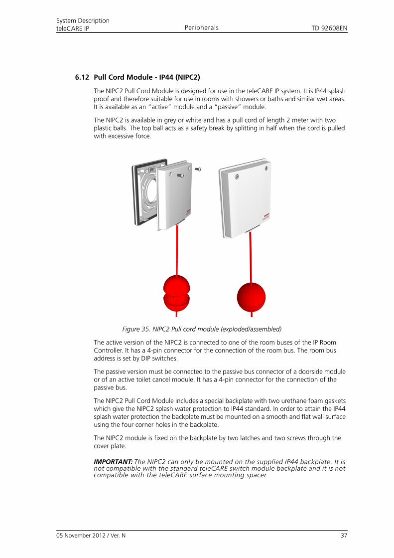
6.12 Pull Cord Module - IP44 (NIPC2)
The NIPC2 Pull Cord Module is designed for use in the teleCARE IP system. It is IP44 splash proof and therefore suitable for use in rooms with showers or baths and similar wet areas. It is available as an “active” module and a “passive” module.
The NIPC2 is available in grey or white and has a pull cord of length 2 meter with two plastic balls. The top ball acts as a safety break by splitting in half when the cord is pulled with excessive force.
Figure 35. NIPC2 Pull cord module (exploded/assembled)
The active version of the NIPC2 is connected to one of the room buses of the IP Room Controller. It has a 4-pin connector for the connection of the room bus. The room bus address is set by DIP switches.
The passive version must be connected to the passive bus connector of a doorside module or of an active toilet cancel module. It has a 4-pin connector for the connection of the passive bus.
The NIPC2 Pull Cord Module includes a special backplate with two urethane foam gaskets which give the NIPC2 splash water protection to IP44 standard. In order to attain the IP44 splash water protection the backplate must be mounted on a smooth and flat wall surface using the four corner holes in the backplate.
The NIPC2 module is fixed on the backplate by two latches and two screws through the cover plate.
IMPORTANT: The NIPC2 can only be mounted on the supplied IP44 backplate. It is not compatible with the standard teleCARE switch module backplate and it is not compatible with the teleCARE surface mounting spacer.
05 November 2012 / Ver. N 37
TD 92608ENSystem DescriptionteleCARE IP Peripherals
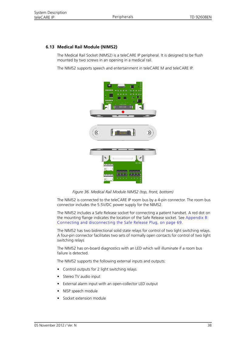
6.13 Medical Rail Module (NIMS2)
The Medical Rail Socket (NIMS2) is a teleCARE IP peripheral. It is designed to be flush mounted by two screws in an opening in a medical rail.
The NIMS2 supports speech and entertainment in teleCARE M and teleCARE IP.
Figure 36. Medical Rail Module NIMS2 (top, front, bottom)
The NIMS2 is connected to the teleCARE IP room bus by a 4-pin connector. The room bus connector includes the 5.5V/DC power supply for the NIMS2.
The NIMS2 includes a Safe Release socket for connecting a patient handset. A red dot on the mounting flange indicates the location of the Safe Release socket. See Appendix B: Connecting and disconnecting the Safe Release Plug, on page 69.
The NIMS2 has two bidirectional solid state relays for control of two light switching relays. A four-pin connector facilitates two sets of normally open contacts for control of two light switching relays
The NIMS2 has on-board diagnostics with an LED which will illuminate if a room bus failure is detected.
The NIMS2 supports the following external inputs and outputs:
• Control outputs for 2 light switching relays
• Stereo TV audio input
• External alarm input with an open-collector LED output
• NISP speech module
• Socket extension module
05 November 2012 / Ver. N 38
TD 92608ENSystem DescriptionteleCARE IP Peripherals
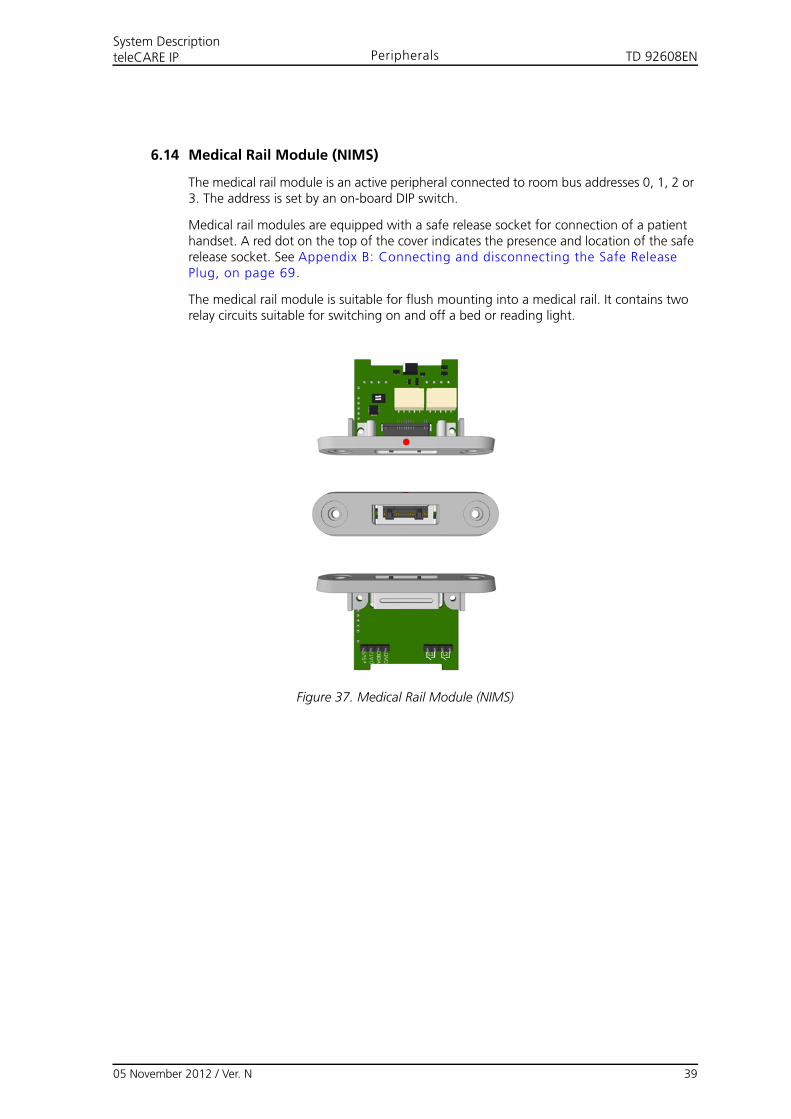
6.14 Medical Rail Module (NIMS)
The medical rail module is an active peripheral connected to room bus addresses 0, 1, 2 or 3. The address is set by an on-board DIP switch.
Medical rail modules are equipped with a safe release socket for connection of a patient handset. A red dot on the top of the cover indicates the presence and location of the safe release socket. See Appendix B: Connecting and disconnecting the Safe Release Plug, on page 69.
The medical rail module is suitable for flush mounting into a medical rail. It contains two relay circuits suitable for switching on and off a bed or reading light.
Figure 37. Medical Rail Module (NIMS)
05 November 2012 / Ver. N 39
TD 92608ENSystem DescriptionteleCARE IP Peripherals
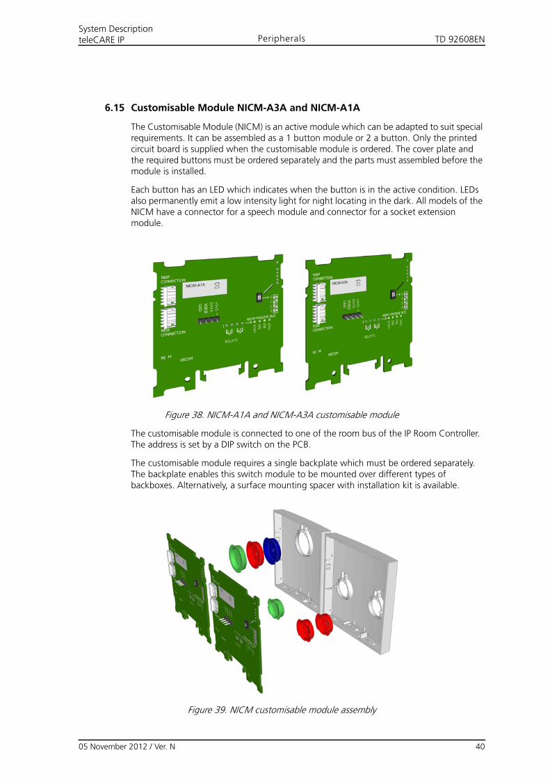
6.15 Customisable Module NICM-A3A and NICM-A1A
The Customisable Module (NICM) is an active module which can be adapted to suit special requirements. It can be assembled as a 1 button module or 2 a button. Only the printed circuit board is supplied when the customisable module is ordered. The cover plate and the required buttons must be ordered separately and the parts must assembled before the module is installed.
Each button has an LED which indicates when the button is in the active condition. LEDs also permanently emit a low intensity light for night locating in the dark. All models of the NICM have a connector for a speech module and connector for a socket extension module.
Figure 38. NICM-A1A and NICM-A3A customisable module
The customisable module is connected to one of the room bus of the IP Room Controller. The address is set by a DIP switch on the PCB.
The customisable module requires a single backplate which must be ordered separately. The backplate enables this switch module to be mounted over different types of backboxes. Alternatively, a surface mounting spacer with installation kit is available.
Figure 39. NICM customisable module assembly
05 November 2012 / Ver. N 40
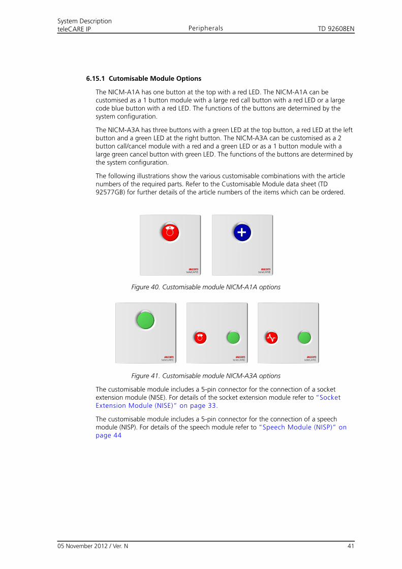
TD 92608ENSystem DescriptionteleCARE IP Peripherals
6.15.1 Cutomisable Module Options
The NICM-A1A has one button at the top with a red LED. The NICM-A1A can be customised as a 1 button module with a large red call button with a red LED or a large code blue button with a red LED. The functions of the buttons are determined by the system configuration.
The NICM-A3A has three buttons with a green LED at the top button, a red LED at the left button and a green LED at the right button. The NICM-A3A can be customised as a 2 button call/cancel module with a red and a green LED or as a 1 button module with a large green cancel button with green LED. The functions of the buttons are determined by the system configuration.
The following illustrations show the various customisable combinations with the article numbers of the required parts. Refer to the Customisable Module data sheet (TD 92577GB) for further details of the article numbers of the items which can be ordered.
Figure 40. Customisable module NICM-A1A options
Figure 41. Customisable module NICM-A3A options
The customisable module includes a 5-pin connector for the connection of a socket extension module (NISE). For details of the socket extension module refer to “Socket Extension Module (NISE)” on page 33.
The customisable module includes a 5-pin connector for the connection of a speech module (NISP). For details of the speech module refer to “Speech Module (NISP)” on page 44
05 November 2012 / Ver. N 41

TD 92608ENSystem DescriptionteleCARE IP Peripherals
6.16 Duty Selector (NIDS)
The duty Selector (NIDS) is an active peripheral with a push button selector switch used for selecting one out of ten (0 to 9) duty configurations.
The duty selector is connected to the teleCARE room bus, in the same way as all other peripherals but it has the fixed room bus address of 5.
A duty selector contains an internal buzzer, two digital inputs and two galvanically isolated outputs via relays. The buzzer can be used to signal calls. The two digital inputs and the two output circuits are available as interfaces to external devices. These inputs and outputs are controlled over the LAN via the room controller.
Note: At the time of publication of this document the digital outputs are not supported yet.
The duty selector enables calls from rooms or beds to be organised in predetermined service groups. Groups or combinations of groups can be assigned to certain positions of the duty selector. Depending on the position selected by the push button, nurse calls from the associated groups are forwarded and reported to the assigned nursing staff.
An explanation of the functions of the duty selector is given in Appendix A: Duty Selector Functions, on page 68.
Figure 42. Duty Selector (NIDS)
The duty selector has the same basic housing as the teleCARE IP single switch modules but it must be mounted on a surface mounting spacer which is delivered with the duty selector.
Note: Only the duty selector NIDS GAA / NIDS WAA can be used in the teleCARE IP system.The teleCARE M duty selector R414370 is not compatible with teleCARE IP.
05 November 2012 / Ver. N 42
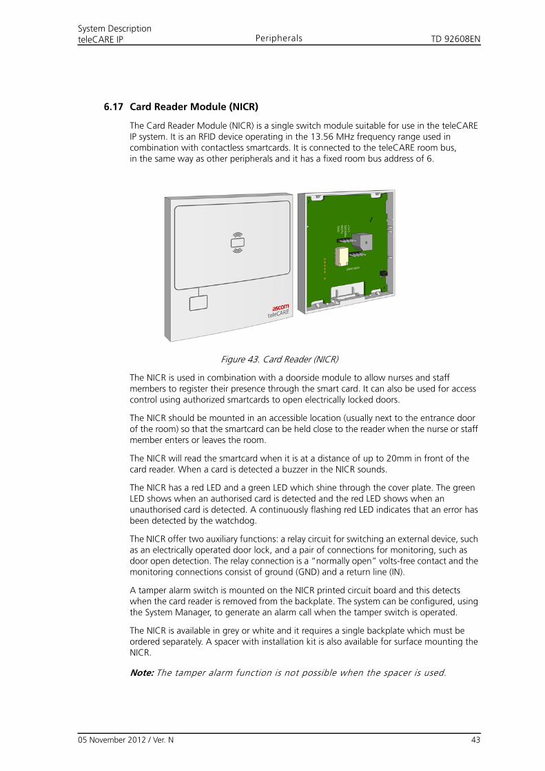
TD 92608ENSystem DescriptionteleCARE IP Peripherals
6.17 Card Reader Module (NICR)
The Card Reader Module (NICR) is a single switch module suitable for use in the teleCARE IP system. It is an RFID device operating in the 13.56 MHz frequency range used in combination with contactless smartcards. It is connected to the teleCARE room bus,in the same way as other peripherals and it has a fixed room bus address of 6.
Figure 43. Card Reader (NICR)
The NICR is used in combination with a doorside module to allow nurses and staff members to register their presence through the smart card. It can also be used for access control using authorized smartcards to open electrically locked doors.
The NICR should be mounted in an accessible location (usually next to the entrance door of the room) so that the smartcard can be held close to the reader when the nurse or staff member enters or leaves the room.
The NICR will read the smartcard when it is at a distance of up to 20mm in front of the card reader. When a card is detected a buzzer in the NICR sounds.
The NICR has a red LED and a green LED which shine through the cover plate. The green LED shows when an authorised card is detected and the red LED shows when an unauthorised card is detected. A continuously flashing red LED indicates that an error has been detected by the watchdog.
The NICR offer two auxiliary functions: a relay circuit for switching an external device, such as an electrically operated door lock, and a pair of connections for monitoring, such as door open detection. The relay connection is a “normally open” volts-free contact and the monitoring connections consist of ground (GND) and a return line (IN).
A tamper alarm switch is mounted on the NICR printed circuit board and this detects when the card reader is removed from the backplate. The system can be configured, using the System Manager, to generate an alarm call when the tamper switch is operated.
The NICR is available in grey or white and it requires a single backplate which must be ordered separately. A spacer with installation kit is also available for surface mounting the NICR.
Note: The tamper alarm function is not possible when the spacer is used.
05 November 2012 / Ver. N 43
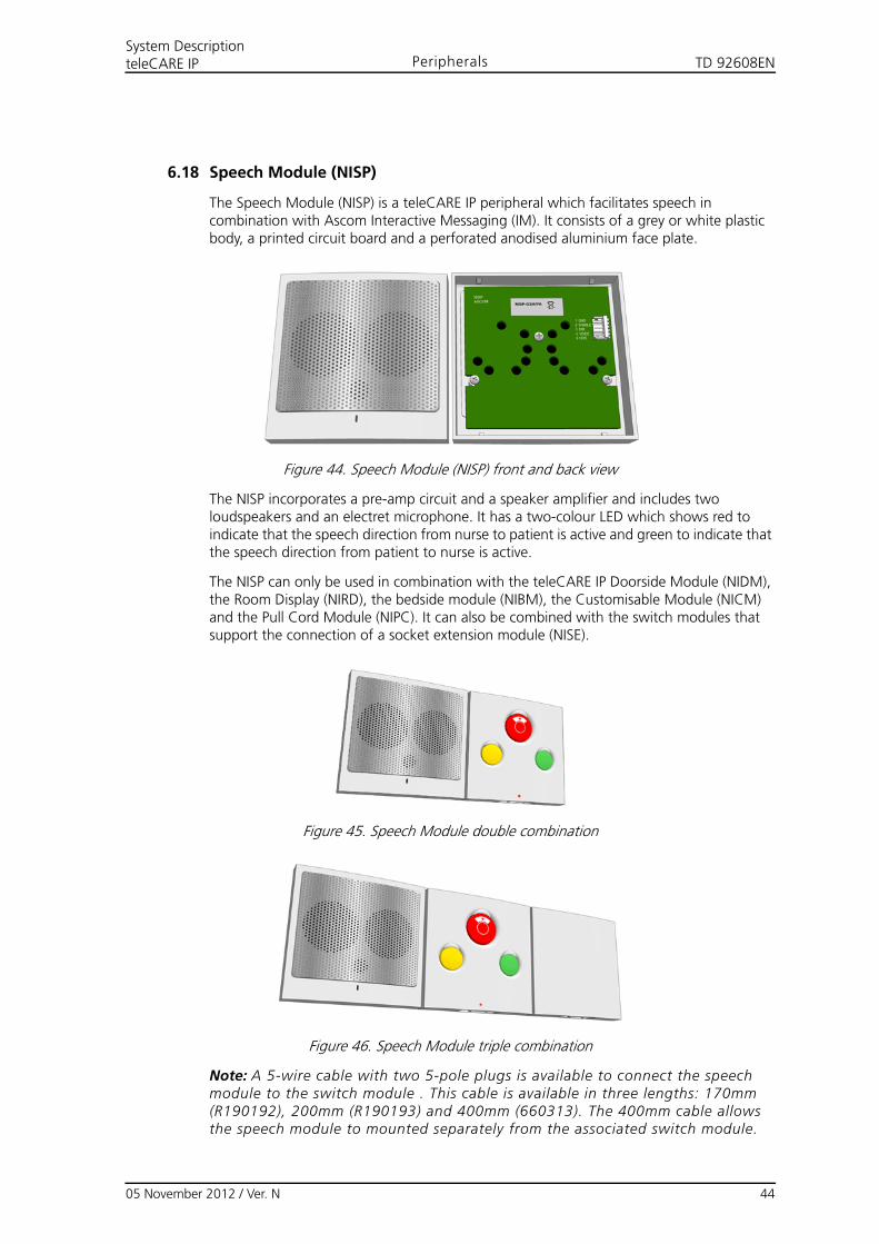
TD 92608ENSystem DescriptionteleCARE IP Peripherals
6.18 Speech Module (NISP)
The Speech Module (NISP) is a teleCARE IP peripheral which facilitates speech in combination with Ascom Interactive Messaging (IM). It consists of a grey or white plastic body, a printed circuit board and a perforated anodised aluminium face plate.
Figure 44. Speech Module (NISP) front and back view
The NISP incorporates a pre-amp circuit and a speaker amplifier and includes two loudspeakers and an electret microphone. It has a two-colour LED which shows red to indicate that the speech direction from nurse to patient is active and green to indicate that the speech direction from patient to nurse is active.
The NISP can only be used in combination with the teleCARE IP Doorside Module (NIDM), the Room Display (NIRD), the bedside module (NIBM), the Customisable Module (NICM) and the Pull Cord Module (NIPC). It can also be combined with the switch modules that support the connection of a socket extension module (NISE).
Figure 45. Speech Module double combination
Figure 46. Speech Module triple combination
Note: A 5-wire cable with two 5-pole plugs is available to connect the speech module to the switch module . This cable is available in three lengths: 170mm (R190192), 200mm (R190193) and 400mm (660313). The 400mm cable allows the speech module to mounted separately from the associated switch module.
05 November 2012 / Ver. N 44
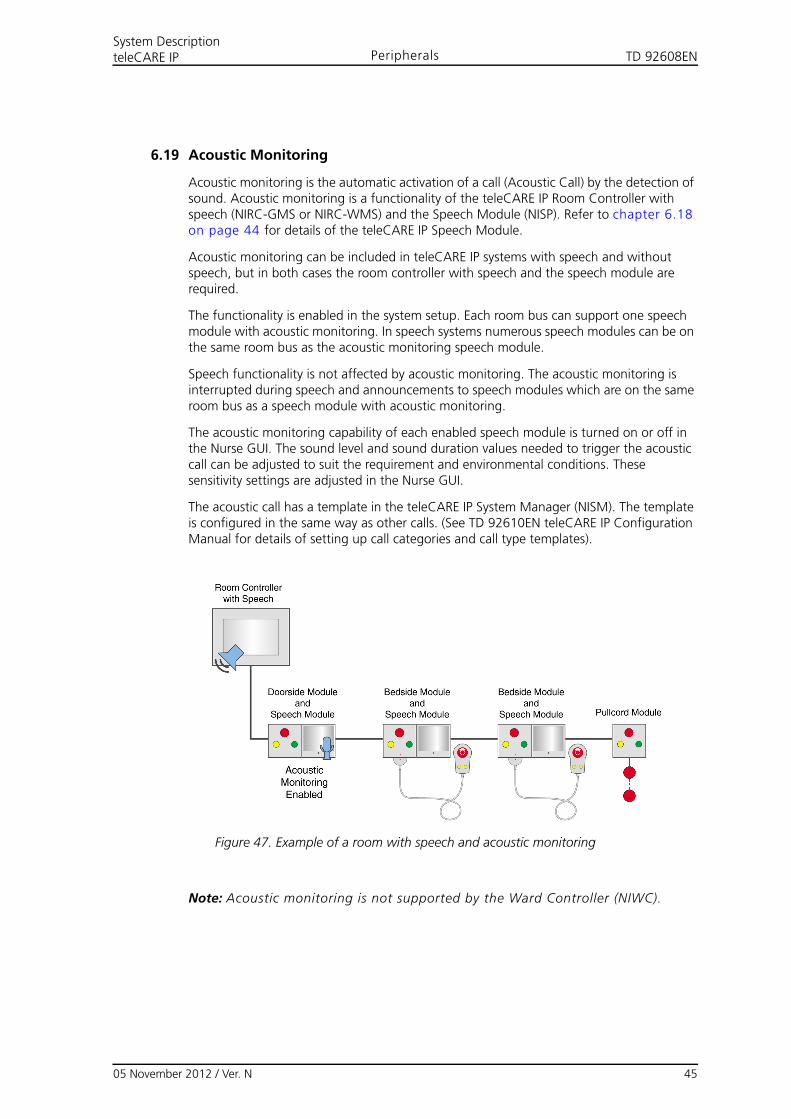
TD 92608ENSystem DescriptionteleCARE IP Peripherals
6.19 Acoustic Monitoring
Acoustic monitoring is the automatic activation of a call (Acoustic Call) by the detection of sound. Acoustic monitoring is a functionality of the teleCARE IP Room Controller with speech (NIRC-GMS or NIRC-WMS) and the Speech Module (NISP). Refer to chapter 6.18 on page 44 for details of the teleCARE IP Speech Module.
Acoustic monitoring can be included in teleCARE IP systems with speech and without speech, but in both cases the room controller with speech and the speech module are required.
The functionality is enabled in the system setup. Each room bus can support one speech module with acoustic monitoring. In speech systems numerous speech modules can be on the same room bus as the acoustic monitoring speech module.
Speech functionality is not affected by acoustic monitoring. The acoustic monitoring is interrupted during speech and announcements to speech modules which are on the same room bus as a speech module with acoustic monitoring.
The acoustic monitoring capability of each enabled speech module is turned on or off in the Nurse GUI. The sound level and sound duration values needed to trigger the acoustic call can be adjusted to suit the requirement and environmental conditions. These sensitivity settings are adjusted in the Nurse GUI.
The acoustic call has a template in the teleCARE IP System Manager (NISM). The template is configured in the same way as other calls. (See TD 92610EN teleCARE IP Configuration Manual for details of setting up call categories and call type templates).
Figure 47. Example of a room with speech and acoustic monitoring
Note: Acoustic monitoring is not supported by the Ward Controller (NIWC).
05 November 2012 / Ver. N 45
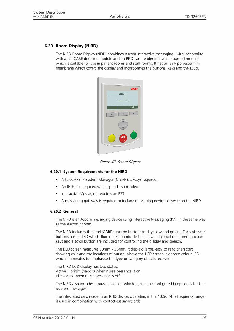
TD 92608ENSystem DescriptionteleCARE IP Peripherals
6.20 Room Display (NIRD)
The NIRD Room Display (NIRD) combines Ascom interactive messaging (IM) functionality, with a teleCARE doorside module and an RFID card reader in a wall mounted module which is suitable for use in patient rooms and staff rooms. It has an EBA polyester film membrane which covers the display and incorporates the buttons, keys and the LEDs.
Figure 48. Room Display
6.20.1 System Requirements for the NIRD
• A teleCARE IP System Manager (NISM) is always required.
• An IP 302 is required when speech is included
• Interactive Messaging requires an ESS
• A messaging gateway is required to include messaging devices other than the NIRD
6.20.2 General
The NIRD is an Ascom messaging device using Interactive Messaging (IM), in the same way as the Ascom phones.
The NIRD includes three teleCARE function buttons (red, yellow and green). Each of these buttons has an LED which illuminates to indicate the activated condition. Three function keys and a scroll button are included for controlling the display and speech.
The LCD screen measures 63mm x 35mm. It displays large, easy to read characters showing calls and the locations of nurses. Above the LCD screen is a three-colour LED which illuminates to emphasise the type or category of calls received.
The NIRD LCD display has two states:Active = bright (backlit) when nurse presence is on Idle = dark when nurse presence is off
The NIRD also includes a buzzer speaker which signals the configured beep codes for the received messages.
The integrated card reader is an RFID device, operating in the 13.56 MHz frequency range, is used in combination with contactless smartcards.
05 November 2012 / Ver. N 46
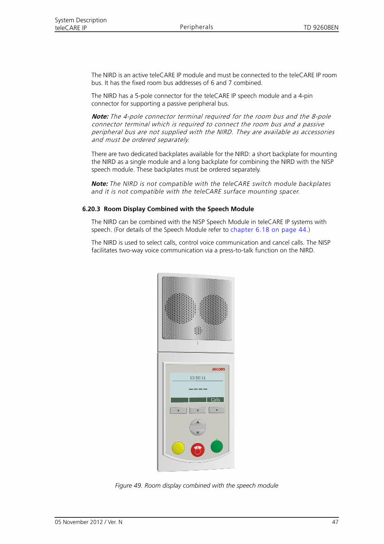
TD 92608ENSystem DescriptionteleCARE IP Peripherals
The NIRD is an active teleCARE IP module and must be connected to the teleCARE IP room bus. It has the fixed room bus addresses of 6 and 7 combined.
The NIRD has a 5-pole connector for the teleCARE IP speech module and a 4-pin connector for supporting a passive peripheral bus.
Note: The 4-pole connector terminal required for the room bus and the 8-pole connector terminal which is required to connect the room bus and a passive peripheral bus are not supplied with the NIRD. They are available as accessories and must be ordered separately.
There are two dedicated backplates available for the NIRD: a short backplate for mounting the NIRD as a single module and a long backplate for combining the NIRD with the NISP speech module. These backplates must be ordered separately.
Note: The NIRD is not compatible with the teleCARE switch module backplates and it is not compatible with the teleCARE surface mounting spacer.
6.20.3 Room Display Combined with the Speech Module
The NIRD can be combined with the NISP Speech Module in teleCARE IP systems with speech. (For details of the Speech Module refer to chapter 6.18 on page 44.)
The NIRD is used to select calls, control voice communication and cancel calls. The NISP facilitates two-way voice communication via a press-to-talk function on the NIRD.
Figure 49. Room display combined with the speech module
05 November 2012 / Ver. N 47
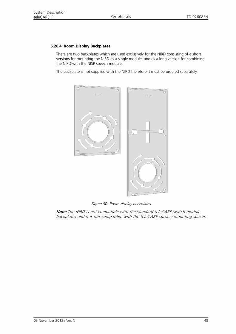
TD 92608ENSystem DescriptionteleCARE IP Peripherals
6.20.4 Room Display Backplates
There are two backplates which are used exclusively for the NIRD consisting of a short versions for mounting the NIRD as a single module, and as a long version for combining the NIRD with the NISP speech module.
The backplate is not supplied with the NIRD therefore it must be ordered separately.
Figure 50. Room display backplates
Note: The NIRD is not compatible with the standard teleCARE switch module backplates and it is not compatible with the teleCARE surface mounting spacer.
05 November 2012 / Ver. N 48
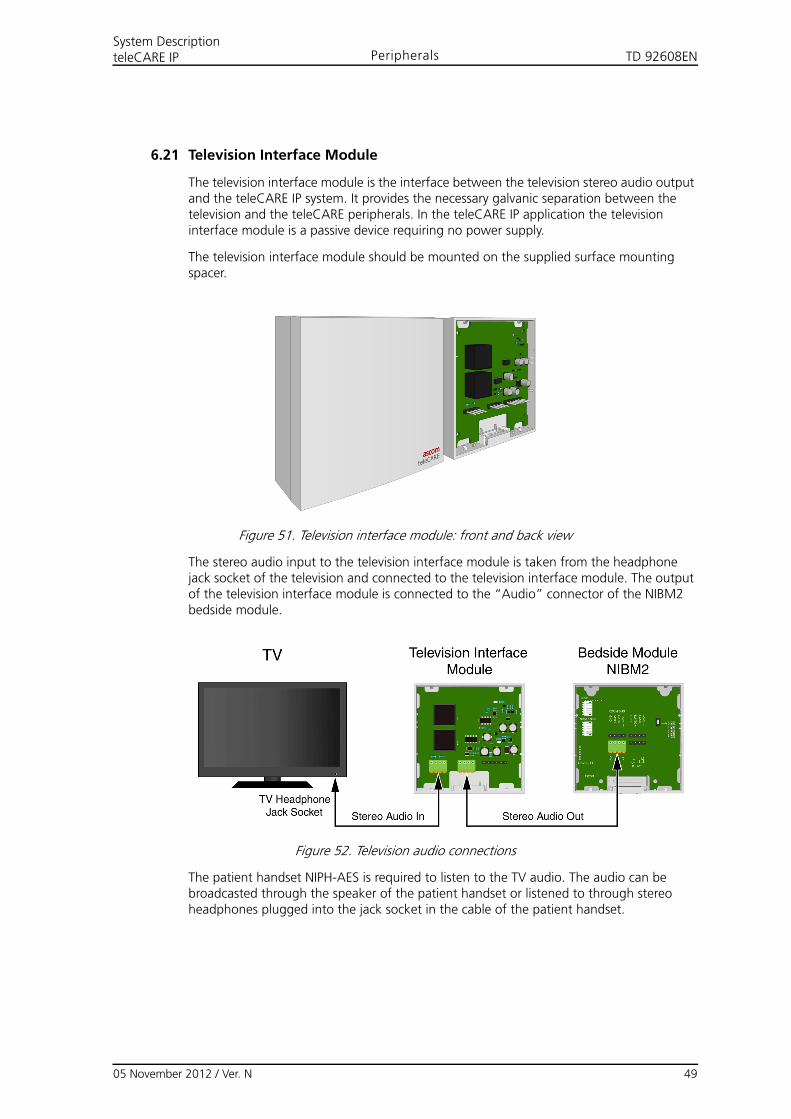
TD 92608ENSystem DescriptionteleCARE IP Peripherals
6.21 Television Interface Module
The television interface module is the interface between the television stereo audio output and the teleCARE IP system. It provides the necessary galvanic separation between the television and the teleCARE peripherals. In the teleCARE IP application the television interface module is a passive device requiring no power supply.
The television interface module should be mounted on the supplied surface mounting spacer.
Figure 51. Television interface module: front and back view
The stereo audio input to the television interface module is taken from the headphone jack socket of the television and connected to the television interface module. The output of the television interface module is connected to the “Audio” connector of the NIBM2 bedside module.
Figure 52. Television audio connections
The patient handset NIPH-AES is required to listen to the TV audio. The audio can be broadcasted through the speaker of the patient handset or listened to through stereo headphones plugged into the jack socket in the cable of the patient handset.
05 November 2012 / Ver. N 49
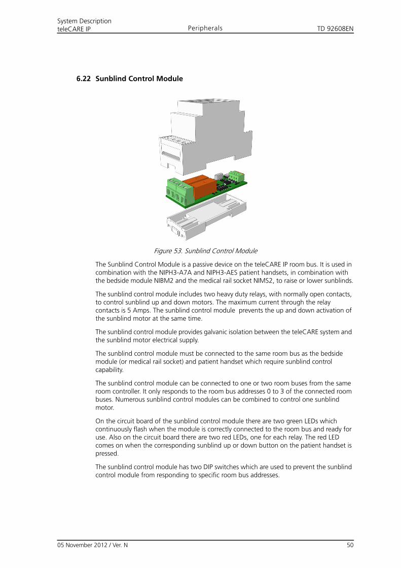
TD 92608ENSystem DescriptionteleCARE IP Peripherals
6.22 Sunblind Control Module
Figure 53. Sunblind Control Module
The Sunblind Control Module is a passive device on the teleCARE IP room bus. It is used in combination with the NIPH3-A7A and NIPH3-AES patient handsets, in combination with the bedside module NIBM2 and the medical rail socket NIMS2, to raise or lower sunblinds.
The sunblind control module includes two heavy duty relays, with normally open contacts, to control sunblind up and down motors. The maximum current through the relay contacts is 5 Amps. The sunblind control module prevents the up and down activation of the sunblind motor at the same time.
The sunblind control module provides galvanic isolation between the teleCARE system and the sunblind motor electrical supply.
The sunblind control module must be connected to the same room bus as the bedside module (or medical rail socket) and patient handset which require sunblind control capability.
The sunblind control module can be connected to one or two room buses from the same room controller. It only responds to the room bus addresses 0 to 3 of the connected room buses. Numerous sunblind control modules can be combined to control one sunblind motor.
On the circuit board of the sunblind control module there are two green LEDs which continuously flash when the module is correctly connected to the room bus and ready for use. Also on the circuit board there are two red LEDs, one for each relay. The red LED comes on when the corresponding sunblind up or down button on the patient handset is pressed.
The sunblind control module has two DIP switches which are used to prevent the sunblind control module from responding to specific room bus addresses.
05 November 2012 / Ver. N 50
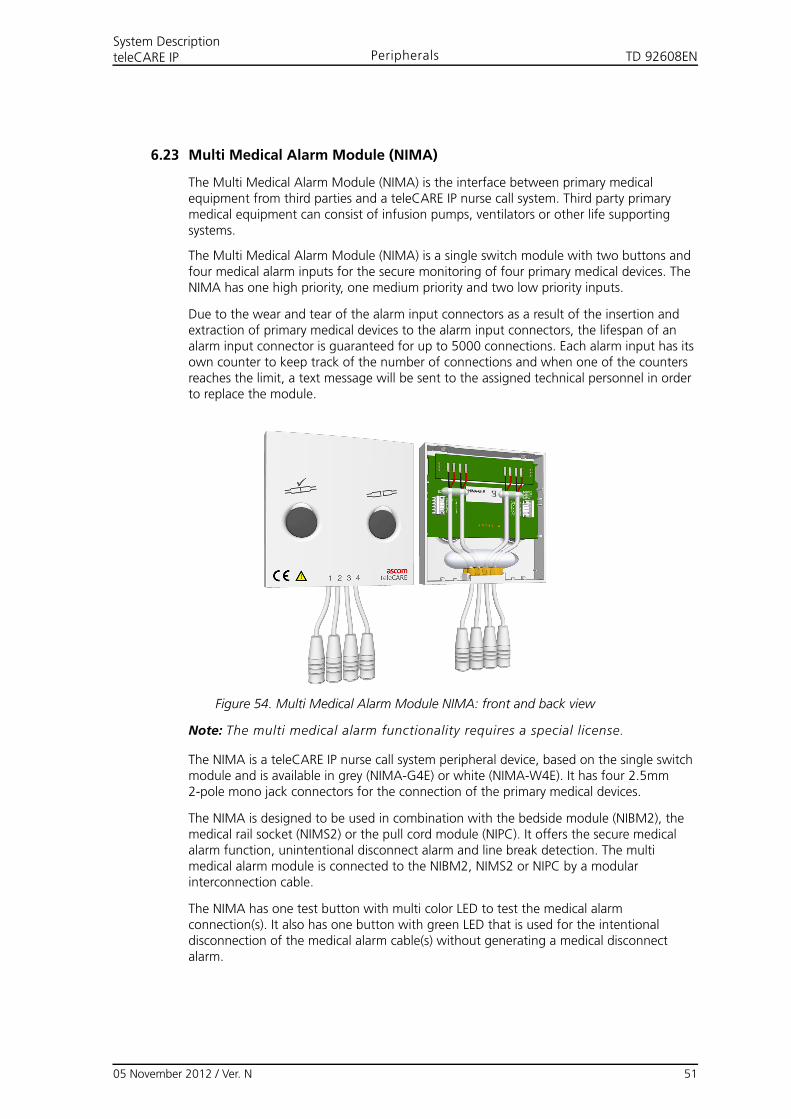
TD 92608ENSystem DescriptionteleCARE IP Peripherals
6.23 Multi Medical Alarm Module (NIMA)
The Multi Medical Alarm Module (NIMA) is the interface between primary medical equipment from third parties and a teleCARE IP nurse call system. Third party primary medical equipment can consist of infusion pumps, ventilators or other life supporting systems.
The Multi Medical Alarm Module (NIMA) is a single switch module with two buttons and four medical alarm inputs for the secure monitoring of four primary medical devices. The NIMA has one high priority, one medium priority and two low priority inputs.
Due to the wear and tear of the alarm input connectors as a result of the insertion and extraction of primary medical devices to the alarm input connectors, the lifespan of an alarm input connector is guaranteed for up to 5000 connections. Each alarm input has its own counter to keep track of the number of connections and when one of the counters reaches the limit, a text message will be sent to the assigned technical personnel in order to replace the module.
Figure 54. Multi Medical Alarm Module NIMA: front and back view
Note: The multi medical alarm functionality requires a special license.
The NIMA is a teleCARE IP nurse call system peripheral device, based on the single switch module and is available in grey (NIMA-G4E) or white (NIMA-W4E). It has four 2.5mm 2-pole mono jack connectors for the connection of the primary medical devices.
The NIMA is designed to be used in combination with the bedside module (NIBM2), the medical rail socket (NIMS2) or the pull cord module (NIPC). It offers the secure medical alarm function, unintentional disconnect alarm and line break detection. The multi medical alarm module is connected to the NIBM2, NIMS2 or NIPC by a modular interconnection cable.
The NIMA has one test button with multi color LED to test the medical alarm connection(s). It also has one button with green LED that is used for the intentional disconnection of the medical alarm cable(s) without generating a medical disconnect alarm.
05 November 2012 / Ver. N 51
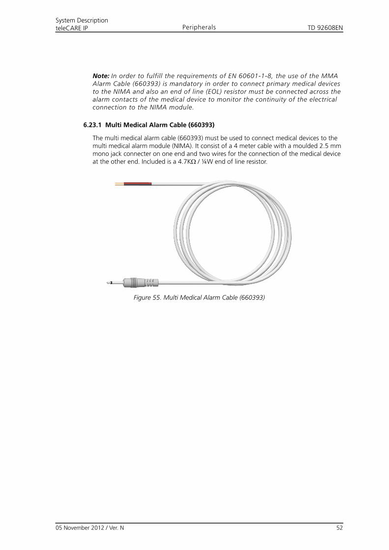
TD 92608ENSystem DescriptionteleCARE IP Peripherals
Note: In order to fulfill the requirements of EN 60601-1-8, the use of the MMA Alarm Cable (660393) is mandatory in order to connect primary medical devices to the NIMA and also an end of line (EOL) resistor must be connected across the alarm contacts of the medical device to monitor the continuity of the electrical connection to the NIMA module.
6.23.1 Multi Medical Alarm Cable (660393)
The multi medical alarm cable (660393) must be used to connect medical devices to the multi medical alarm module (NIMA). It consist of a 4 meter cable with a moulded 2.5 mm mono jack connecter on one end and two wires for the connection of the medical device at the other end. Included is a 4.7K/ ¼W end of line resistor.
Figure 55. Multi Medical Alarm Cable (660393)
05 November 2012 / Ver. N 52
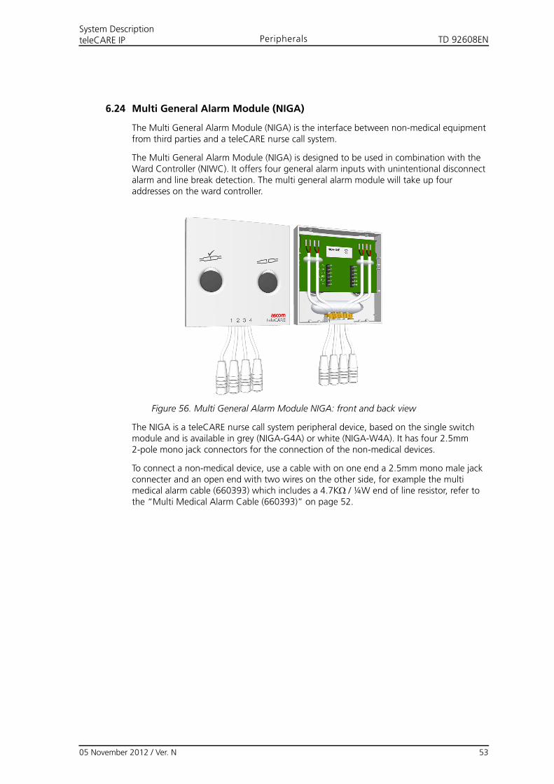
TD 92608ENSystem DescriptionteleCARE IP Peripherals
6.24 Multi General Alarm Module (NIGA)
The Multi General Alarm Module (NIGA) is the interface between non-medical equipment from third parties and a teleCARE nurse call system.
The Multi General Alarm Module (NIGA) is designed to be used in combination with the Ward Controller (NIWC). It offers four general alarm inputs with unintentional disconnect alarm and line break detection. The multi general alarm module will take up four addresses on the ward controller.
Figure 56. Multi General Alarm Module NIGA: front and back view
The NIGA is a teleCARE nurse call system peripheral device, based on the single switch module and is available in grey (NIGA-G4A) or white (NIGA-W4A). It has four 2.5mm 2-pole mono jack connectors for the connection of the non-medical devices.
To connect a non-medical device, use a cable with on one end a 2.5mm mono male jack connecter and an open end with two wires on the other side, for example the multi medical alarm cable (660393) which includes a 4.7K/ ¼W end of line resistor, refer to the “Multi Medical Alarm Cable (660393)” on page 52.
05 November 2012 / Ver. N 53
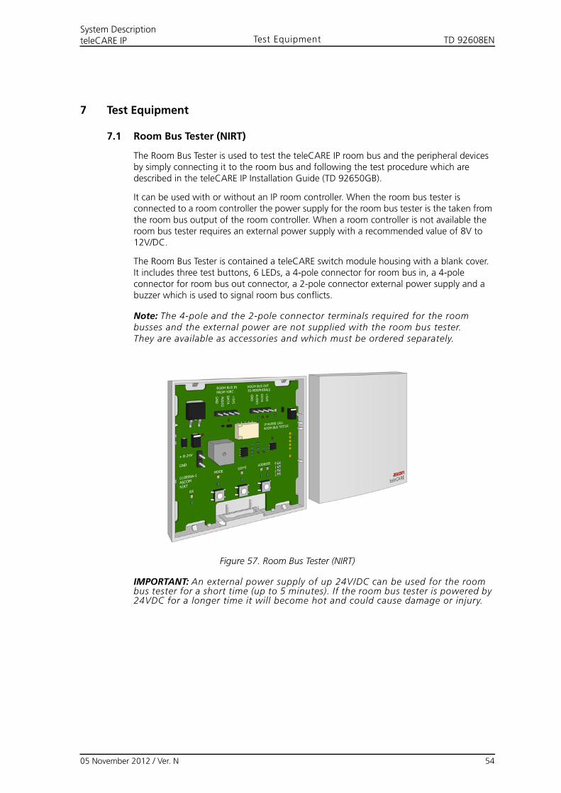
TD 92608EN
05 November 2012 / Ver. N 54
System DescriptionteleCARE IP Test Equipment
7 Test Equipment
7.1 Room Bus Tester (NIRT)
The Room Bus Tester is used to test the teleCARE IP room bus and the peripheral devices by simply connecting it to the room bus and following the test procedure which are described in the teleCARE IP Installation Guide (TD 92650GB).
It can be used with or without an IP room controller. When the room bus tester is connected to a room controller the power supply for the room bus tester is the taken from the room bus output of the room controller. When a room controller is not available the room bus tester requires an external power supply with a recommended value of 8V to 12V/DC.
The Room Bus Tester is contained a teleCARE switch module housing with a blank cover. It includes three test buttons, 6 LEDs, a 4-pole connector for room bus in, a 4-pole connector for room bus out connector, a 2-pole connector external power supply and a buzzer which is used to signal room bus conflicts.
Note: The 4-pole and the 2-pole connector terminals required for the room busses and the external power are not supplied with the room bus tester.They are available as accessories and which must be ordered separately.
Figure 57. Room Bus Tester (NIRT)
IMPORTANT: An external power supply of up 24V/DC can be used for the room bus tester for a short time (up to 5 minutes). If the room bus tester is powered by 24VDC for a longer time it will become hot and could cause damage or injury.
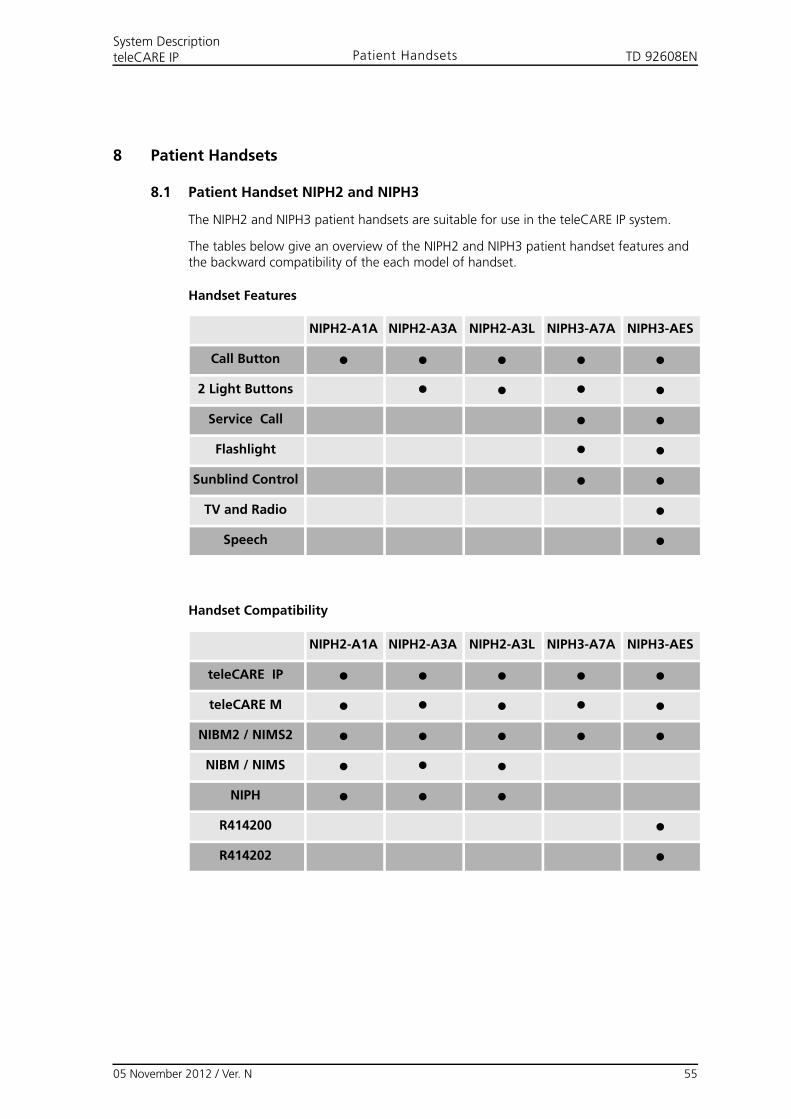
TD 92608ENSystem DescriptionteleCARE IP Patient Handsets
8 Patient Handsets
8.1 Patient Handset NIPH2 and NIPH3
The NIPH2 and NIPH3 patient handsets are suitable for use in the teleCARE IP system.
The tables below give an overview of the NIPH2 and NIPH3 patient handset features and the backward compatibility of the each model of handset.
Handset Features
Handset Compatibility
NIPH2-A1A NIPH2-A3A NIPH2-A3L NIPH3-A7A NIPH3-AES
Call Button ● ● ● ● ●
2 Light Buttons ● ● ● ●
Service Call ● ●
Flashlight ● ●
Sunblind Control ● ●
TV and Radio ●
Speech ●
NIPH2-A1A NIPH2-A3A NIPH2-A3L NIPH3-A7A NIPH3-AES
teleCARE IP ● ● ● ● ●
teleCARE M ● ● ● ● ●
NIBM2 / NIMS2 ● ● ● ● ●
NIBM / NIMS ● ● ●
NIPH ● ● ●
R414200 ●
R414202 ●
05 November 2012 / Ver. N 55
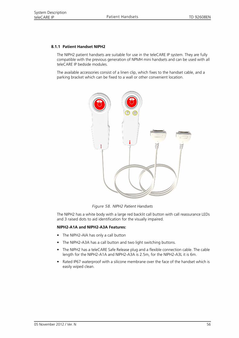
TD 92608ENSystem DescriptionteleCARE IP Patient Handsets
8.1.1 Patient Handset NIPH2
The NIPH2 patient handsets are suitable for use in the teleCARE IP system. They are fully compatible with the previous generation of NPMH mini handsets and can be used with all teleCARE IP bedside modules.
The available accessories consist of a linen clip, which fixes to the handset cable, and a parking bracket which can be fixed to a wall or other convenient location.
Figure 58. NIPH2 Patient Handsets
The NIPH2 has a white body with a large red backlit call button with call reassurance LEDs and 3 raised dots to aid identification for the visually impaired.
NIPH2-A1A and NIPH2-A3A Features:
• The NIPH2-AIA has only a call button
• The NIPH2-A3A has a call button and two light switching buttons.
• The NIPH2 has a teleCARE Safe Release plug and a flexible connection cable. The cable length for the NIPH2-A1A and NIPH2-A3A is 2.5m, for the NIPH2-A3L it is 6m.
• Rated IP67 waterproof with a silicone membrane over the face of the handset which is easily wiped clean.
05 November 2012 / Ver. N 56
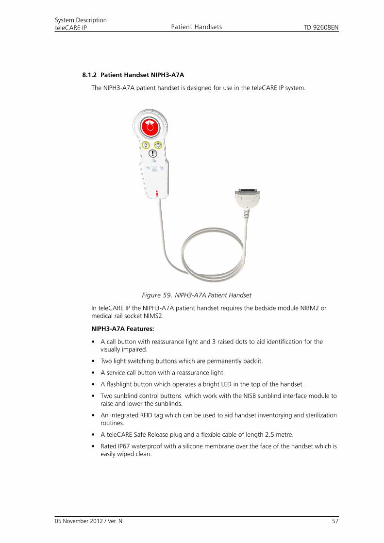
TD 92608ENSystem DescriptionteleCARE IP Patient Handsets
8.1.2 Patient Handset NIPH3-A7A
The NIPH3-A7A patient handset is designed for use in the teleCARE IP system.
Figure 59. NIPH3-A7A Patient Handset
In teleCARE IP the NIPH3-A7A patient handset requires the bedside module NIBM2 or medical rail socket NIMS2.
NIPH3-A7A Features:
• A call button with reassurance light and 3 raised dots to aid identification for the visually impaired.
• Two light switching buttons which are permanently backlit.
• A service call button with a reassurance light.
• A flashlight button which operates a bright LED in the top of the handset.
• Two sunblind control buttons which work with the NISB sunblind interface module to raise and lower the sunblinds.
• An integrated RFID tag which can be used to aid handset inventorying and sterilization routines.
• A teleCARE Safe Release plug and a flexible cable of length 2.5 metre.
• Rated IP67 waterproof with a silicone membrane over the face of the handset which is easily wiped clean.
05 November 2012 / Ver. N 57
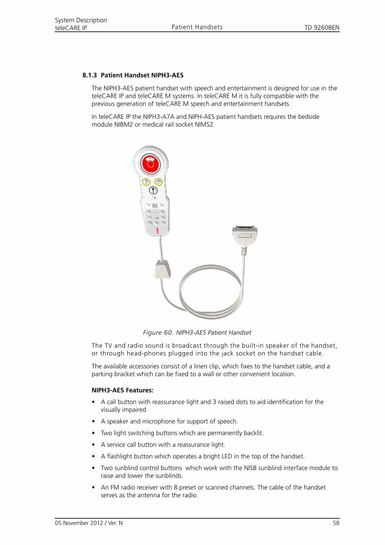
TD 92608ENSystem DescriptionteleCARE IP Patient Handsets
8.1.3 Patient Handset NIPH3-AES
The NIPH3-AES patient handset with speech and entertainment is designed for use in the teleCARE IP and teleCARE M systems. In teleCARE M it is fully compatible with the previous generation of teleCARE M speech and entertainment handsets.
In teleCARE IP the NIPH3-A7A and NIPH-AES patient handsets requires the bedside module NIBM2 or medical rail socket NIMS2.
Figure 60. NIPH3-AES Patient Handset
The TV and radio sound is broadcast through the built-in speaker of the handset, or through head-phones plugged into the jack socket on the handset cable.
The available accessories consist of a linen clip, which fixes to the handset cable, and a parking bracket which can be fixed to a wall or other convenient location.
NIPH3-AES Features:
• A call button with reassurance light and 3 raised dots to aid identification for the visually impaired
• A speaker and microphone for support of speech.
• Two light switching buttons which are permanently backlit.
• A service call button with a reassurance light.
• A flashlight button which operates a bright LED in the top of the handset.
• Two sunblind control buttons which work with the NISB sunblind interface module to raise and lower the sunblinds.
• An FM radio receiver with 8 preset or scanned channels. The cable of the handset serves as the antenna for the radio.
05 November 2012 / Ver. N 58
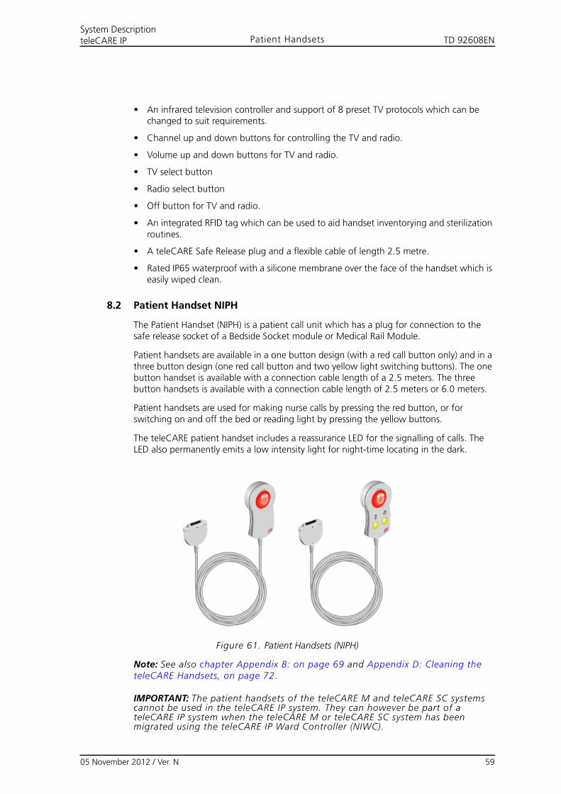
TD 92608ENSystem DescriptionteleCARE IP Patient Handsets
• An infrared television controller and support of 8 preset TV protocols which can be changed to suit requirements.
• Channel up and down buttons for controlling the TV and radio.
• Volume up and down buttons for TV and radio.
• TV select button
• Radio select button
• Off button for TV and radio.
• An integrated RFID tag which can be used to aid handset inventorying and sterilization routines.
• A teleCARE Safe Release plug and a flexible cable of length 2.5 metre.
• Rated IP65 waterproof with a silicone membrane over the face of the handset which is easily wiped clean.
8.2 Patient Handset NIPH
The Patient Handset (NIPH) is a patient call unit which has a plug for connection to the safe release socket of a Bedside Socket module or Medical Rail Module.
Patient handsets are available in a one button design (with a red call button only) and in a three button design (one red call button and two yellow light switching buttons). The one button handset is available with a connection cable length of a 2.5 meters. The three button handsets is available with a connection cable length of 2.5 meters or 6.0 meters.
Patient handsets are used for making nurse calls by pressing the red button, or for switching on and off the bed or reading light by pressing the yellow buttons.
The teleCARE patient handset includes a reassurance LED for the signalling of calls. The LED also permanently emits a low intensity light for night-time locating in the dark.
Figure 61. Patient Handsets (NIPH)
Note: See also chapter Appendix B: on page 69 and Appendix D: Cleaning the teleCARE Handsets, on page 72.
IMPORTANT: The patient handsets of the teleCARE M and teleCARE SC systems cannot be used in the teleCARE IP system. They can however be part of a teleCARE IP system when the teleCARE M or teleCARE SC system has been migrated using the teleCARE IP Ward Controller (NIWC).
05 November 2012 / Ver. N 59
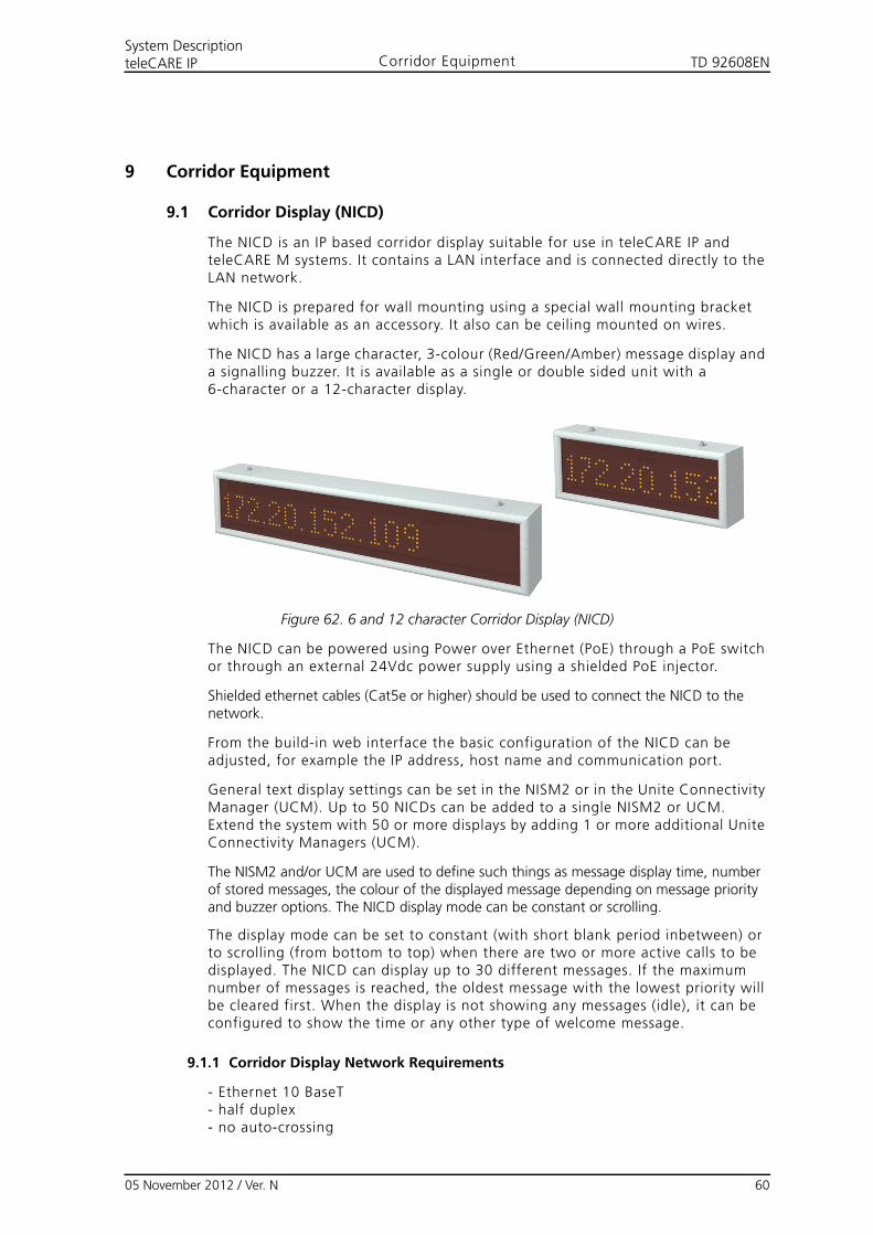
TD 92608ENSystem DescriptionteleCARE IP Corridor Equipment
9 Corridor Equipment
9.1 Corridor Display (NICD)
The NICD is an IP based corridor display suitable for use in teleCARE IP and teleCARE M systems. It contains a LAN interface and is connected directly to the LAN network.
The NICD is prepared for wall mounting using a special wall mounting bracket which is available as an accessory. It also can be ceiling mounted on wires.
The NICD has a large character, 3-colour (Red/Green/Amber) message display and a signalling buzzer. It is available as a single or double sided unit with a 6-character or a 12-character display.
Figure 62. 6 and 12 character Corridor Display (NICD)
The NICD can be powered using Power over Ethernet (PoE) through a PoE switch or through an external 24Vdc power supply using a shielded PoE injector.
Shielded ethernet cables (Cat5e or higher) should be used to connect the NICD to the network.
From the build-in web interface the basic configuration of the NICD can be adjusted, for example the IP address, host name and communication port.
General text display settings can be set in the NISM2 or in the Unite Connectivity Manager (UCM). Up to 50 NICDs can be added to a single NISM2 or UCM. Extend the system with 50 or more displays by adding 1 or more additional Unite Connectivity Managers (UCM).
The NISM2 and/or UCM are used to define such things as message display time, number of stored messages, the colour of the displayed message depending on message priority and buzzer options. The NICD display mode can be constant or scrolling.
The display mode can be set to constant (with short blank period inbetween) or to scrolling (from bottom to top) when there are two or more active calls to be displayed. The NICD can display up to 30 different messages. If the maximum number of messages is reached, the oldest message with the lowest priority will be cleared first. When the display is not showing any messages (idle), it can be configured to show the time or any other type of welcome message.
9.1.1 Corridor Display Network Requirements
- Ethernet 10 BaseT- half duplex- no auto-crossing
05 November 2012 / Ver. N 60
TD 92608ENSystem DescriptionteleCARE IP Corridor Equipment
- no auto-negotiation- no auto-polarity
Note: The display will not work on non-standard (reversed polarity) switches using a normal straight cable. Reversed polarity switches require a special Reverse Polarity Cable.
05 November 2012 / Ver. N 61
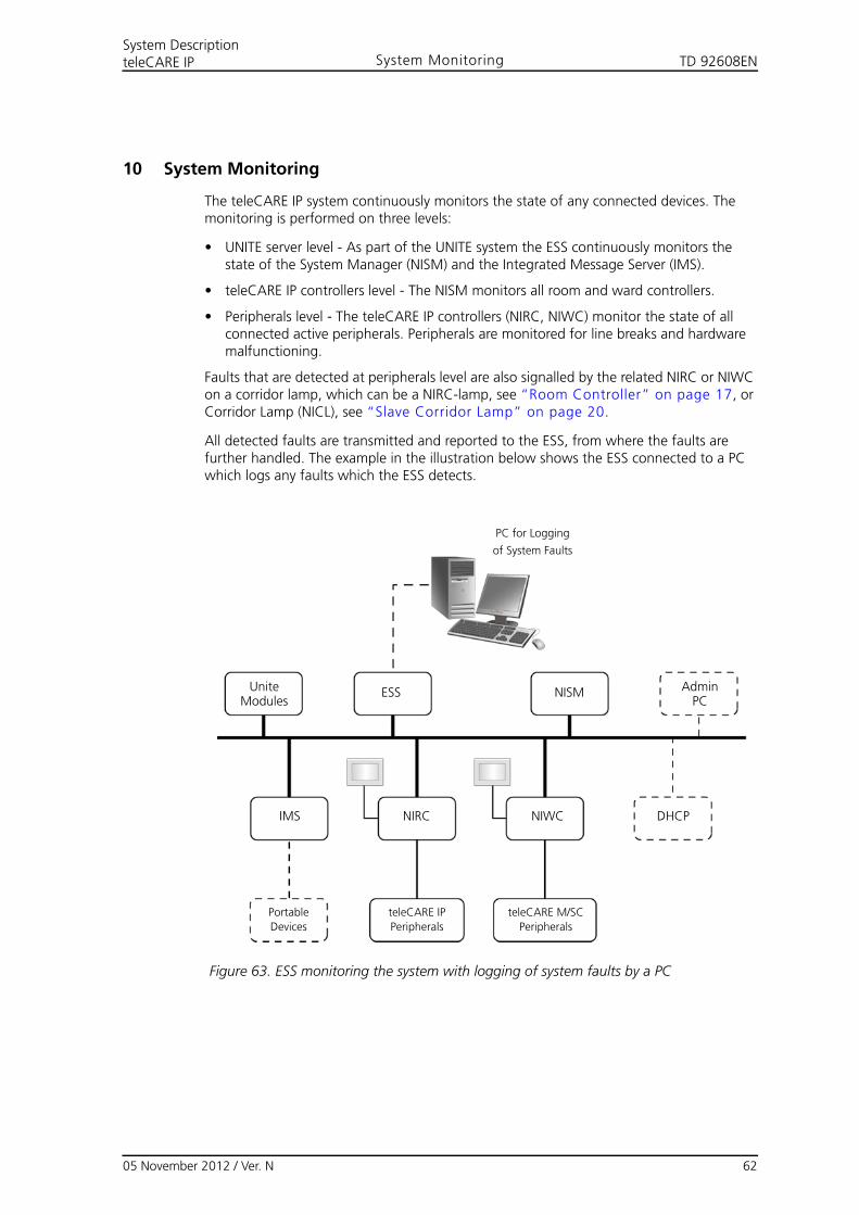
TD 92608EN
05 November 2012 / Ver. N 62
System DescriptionteleCARE IP System Monitoring
10 System Monitoring
The teleCARE IP system continuously monitors the state of any connected devices. The monitoring is performed on three levels:
• UNITE server level - As part of the UNITE system the ESS continuously monitors the state of the System Manager (NISM) and the Integrated Message Server (IMS).
• teleCARE IP controllers level - The NISM monitors all room and ward controllers.
• Peripherals level - The teleCARE IP controllers (NIRC, NIWC) monitor the state of all connected active peripherals. Peripherals are monitored for line breaks and hardware malfunctioning.
Faults that are detected at peripherals level are also signalled by the related NIRC or NIWC on a corridor lamp, which can be a NIRC-lamp, see “Room Controller” on page 17, or Corridor Lamp (NICL), see “Slave Corridor Lamp” on page 20.
All detected faults are transmitted and reported to the ESS, from where the faults are further handled. The example in the illustration below shows the ESS connected to a PC which logs any faults which the ESS detects.
Figure 63. ESS monitoring the system with logging of system faults by a PC
AdminPC
UniteModules
Portable
Devices
teleCARE IP
Peripherals
teleCARE M/SC
Peripherals
ESS NISM
IMS NIRC NIWC DHCP
PC for Logging
of System Faults
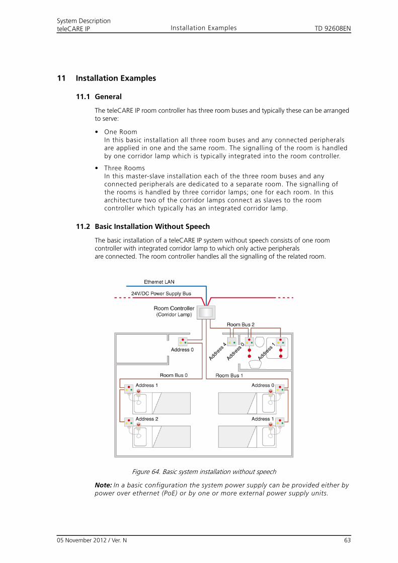
TD 92608ENSystem DescriptionteleCARE IP Installation Examples
11 Installation Examples
11.1 General
The teleCARE IP room controller has three room buses and typically these can be arranged to serve:
• One RoomIn this basic installation all three room buses and any connected peripherals are applied in one and the same room. The signalling of the room is handled by one corridor lamp which is typically integrated into the room controller.
• Three RoomsIn this master-slave installation each of the three room buses and any connected peripherals are dedicated to a separate room. The signalling of the rooms is handled by three corridor lamps; one for each room. In this architecture two of the corridor lamps connect as slaves to the room controller which typically has an integrated corridor lamp.
11.2 Basic Installation Without Speech
The basic installation of a teleCARE IP system without speech consists of one room controller with integrated corridor lamp to which only active peripheralsare connected. The room controller handles all the signalling of the related room.
Figure 64. Basic system installation without speech
Note: In a basic configuration the system power supply can be provided either by power over ethernet (PoE) or by one or more external power supply units.
05 November 2012 / Ver. N 63
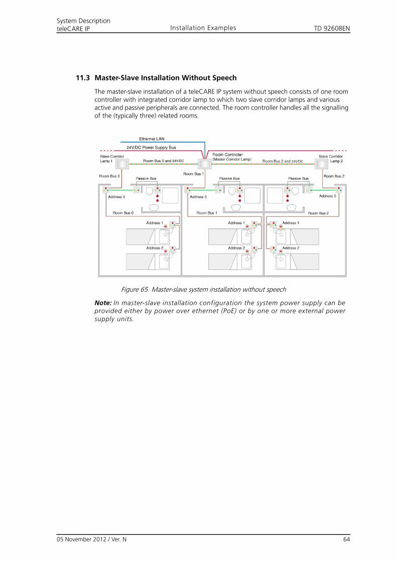
TD 92608ENSystem DescriptionteleCARE IP Installation Examples
11.3 Master-Slave Installation Without Speech
The master-slave installation of a teleCARE IP system without speech consists of one room controller with integrated corridor lamp to which two slave corridor lamps and various active and passive peripherals are connected. The room controller handles all the signalling of the (typically three) related rooms.
Figure 65. Master-slave system installation without speech
Note: In master-slave installation configuration the system power supply can be provided either by power over ethernet (PoE) or by one or more external power supply units.
05 November 2012 / Ver. N 64
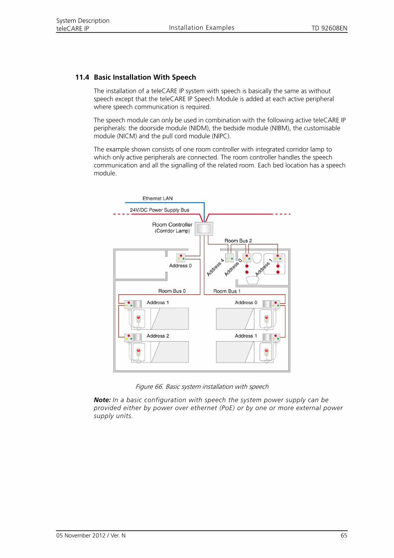
TD 92608ENSystem DescriptionteleCARE IP Installation Examples
11.4 Basic Installation With Speech
The installation of a teleCARE IP system with speech is basically the same as without speech except that the teleCARE IP Speech Module is added at each active peripheral where speech communication is required.
The speech module can only be used in combination with the following active teleCARE IP peripherals: the doorside module (NIDM), the bedside module (NIBM), the customisable module (NICM) and the pull cord module (NIPC).
The example shown consists of one room controller with integrated corridor lamp to which only active peripherals are connected. The room controller handles the speech communication and all the signalling of the related room. Each bed location has a speech module.
Figure 66. Basic system installation with speech
Note: In a basic configuration with speech the system power supply can be provided either by power over ethernet (PoE) or by one or more external power supply units.
05 November 2012 / Ver. N 65
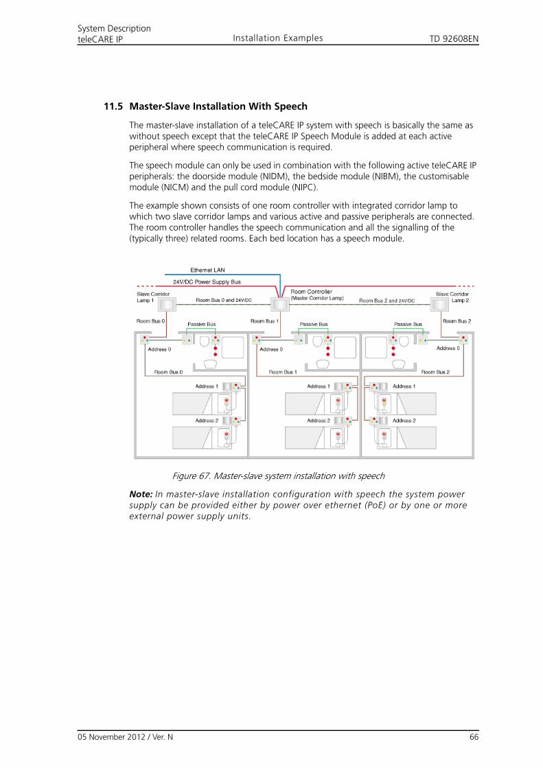
TD 92608ENSystem DescriptionteleCARE IP Installation Examples
11.5 Master-Slave Installation With Speech
The master-slave installation of a teleCARE IP system with speech is basically the same as without speech except that the teleCARE IP Speech Module is added at each active peripheral where speech communication is required.
The speech module can only be used in combination with the following active teleCARE IP peripherals: the doorside module (NIDM), the bedside module (NIBM), the customisable module (NICM) and the pull cord module (NIPC).
The example shown consists of one room controller with integrated corridor lamp to which two slave corridor lamps and various active and passive peripherals are connected. The room controller handles the speech communication and all the signalling of the (typically three) related rooms. Each bed location has a speech module.
Figure 67. Master-slave system installation with speech
Note: In master-slave installation configuration with speech the system power supply can be provided either by power over ethernet (PoE) or by one or more external power supply units.
05 November 2012 / Ver. N 66
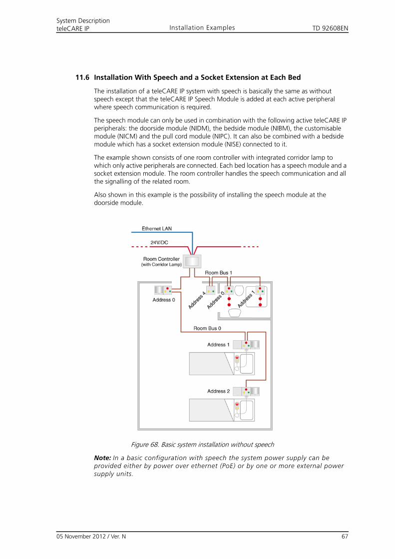
TD 92608ENSystem DescriptionteleCARE IP Installation Examples
11.6 Installation With Speech and a Socket Extension at Each Bed
The installation of a teleCARE IP system with speech is basically the same as without speech except that the teleCARE IP Speech Module is added at each active peripheral where speech communication is required.
The speech module can only be used in combination with the following active teleCARE IP peripherals: the doorside module (NIDM), the bedside module (NIBM), the customisable module (NICM) and the pull cord module (NIPC). It can also be combined with a bedside module which has a socket extension module (NISE) connected to it.
The example shown consists of one room controller with integrated corridor lamp to which only active peripherals are connected. Each bed location has a speech module and a socket extension module. The room controller handles the speech communication and all the signalling of the related room.
Also shown in this example is the possibility of installing the speech module at the doorside module.
Figure 68. Basic system installation without speech
Note: In a basic configuration with speech the system power supply can be provided either by power over ethernet (PoE) or by one or more external power supply units.
05 November 2012 / Ver. N 67
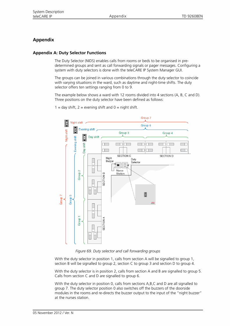
TD 92608ENSystem DescriptionteleCARE IP Appendix
Appendix
Appendix A: Duty Selector Functions
The Duty Selector (NIDS) enables calls from rooms or beds to be organised in pre-determined groups and sent as call forwarding signals or pager messages. Configuring a system with duty selectors is done with the teleCARE IP System Manager GUI.
The groups can be joined in various combinations through the duty selector to coincide with varying situations in the ward, such as daytime and night-time shifts. The duty selector offers ten settings ranging from 0 to 9.
The example below shows a ward with 12 rooms divided into 4 sections (A, B, C and D). Three positions on the duty selector have been defined as follows:
1 = day shift, 2 = evening shift and 0 = night shift.
Figure 69. Duty selector and call forwarding groups
With the duty selector in position 1, calls from section A will be signalled to group 1, section B will be signalled to group 2, section C to group 3 and section D to group 4.
With the duty selector is in position 2, calls from section A and B are signalled to group 5. Calls from section C and D are signalled to group 6.
With the duty selector in position 0, calls from sections A,B,C and D are all signalled to group 7. The duty selector position 0 also switches off the buzzers of the doorside modules in the rooms and re-directs the buzzer output to the input of the “night buzzer” at the nurses station.
05 November 2012 / Ver. N
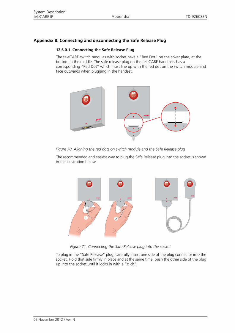
TD 92608ENSystem DescriptionteleCARE IP Appendix
Appendix B: Connecting and disconnecting the Safe Release Plug
12.6.0.1 Connecting the Safe Release Plug
The teleCARE switch modules with socket have a “Red Dot” on the cover plate, at the bottom in the middle. The safe release plug on the teleCARE hand sets has a corresponding “Red Dot” which must line up with the red dot on the switch module and face outwards when plugging in the handset.
Figure 70. Aligning the red dots on switch module and the Safe Release plug
The recommended and easiest way to plug the Safe Release plug into the socket is shown in the illustration below.
Figure 71. Connecting the Safe Release plug into the socket
To plug in the “Safe Release” plug, carefully insert one side of the plug connector into the socket. Hold that side firmly in place and at the same time, push the other side of the plug up into the socket until it locks in with a “click”.
05 November 2012 / Ver. N
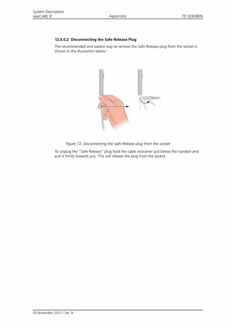
TD 92608ENSystem DescriptionteleCARE IP Appendix
12.6.0.2 Disconnecting the Safe Release Plug
The recommended and easiest way to remove the Safe Release plug from the socket is shown in the illustration below:
Figure 72. Disconnecting the Safe Release plug from the socket
To unplug the “Safe Release” plug hold the cable restrainer just below the handset and pull it firmly towards you. This will release the plug from the socket.
05 November 2012 / Ver. N
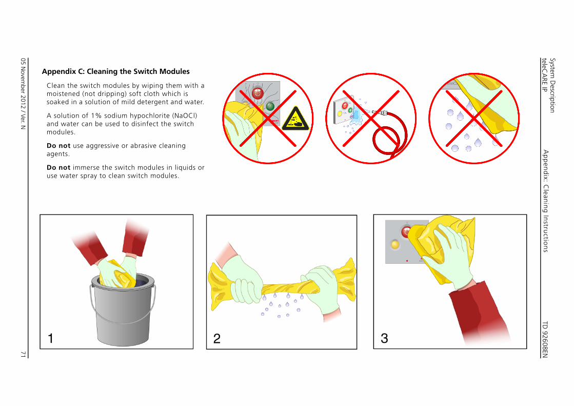
TD 92608EN
05 Novem
ber 2012 / Ver. N
System D
escriptionteleC
ARE IP
71
Ap
pen
dix: C
leanin
g In
structio
ns
Ap
Clmso
Aanm
Dag
Dus
pendix C: Cleaning the Switch Modules
ean the switch modules by wiping them with a oistened (not dripping) soft cloth which is aked in a solution of mild detergent and water.
solution of 1% sodium hypochlorite (NaOCl) d water can be used to disinfect the switch odules.
o not use aggressive or abrasive cleaning ents.
o not immerse the switch modules in liquids or e water spray to clean switch modules.
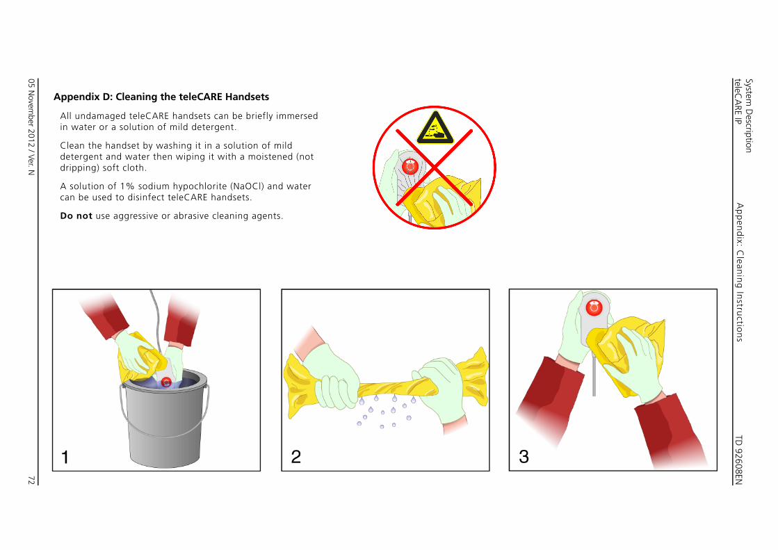
TD 92608EN
05 Novem
ber 2012 / Ver. N
System D
escriptionteleC
ARE IP
72
Ap
pen
dix: C
leanin
g In
structio
ns
App
Allin
Clededri
A scan
Do
endix D: Cleaning the teleCARE Handsets
undamaged teleCARE handsets can be briefly immersed water or a solution of mild detergent.
an the handset by washing it in a solution of mild tergent and water then wiping it with a moistened (not pping) soft cloth.
olution of 1% sodium hypochlorite (NaOCl) and water be used to disinfect teleCARE handsets.
not use aggressive or abrasive cleaning agents.
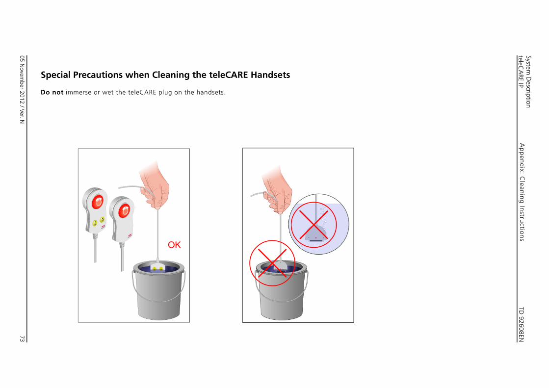
TD 92608EN
05 Novem
ber 2012 / Ver. N
System D
escriptionteleC
ARE IP
73
Ap
pen
dix: C
leanin
g In
structio
ns
Sp
Do
ecial Precautions when Cleaning the teleCARE Handsets
not immerse or wet the teleCARE plug on the handsets.
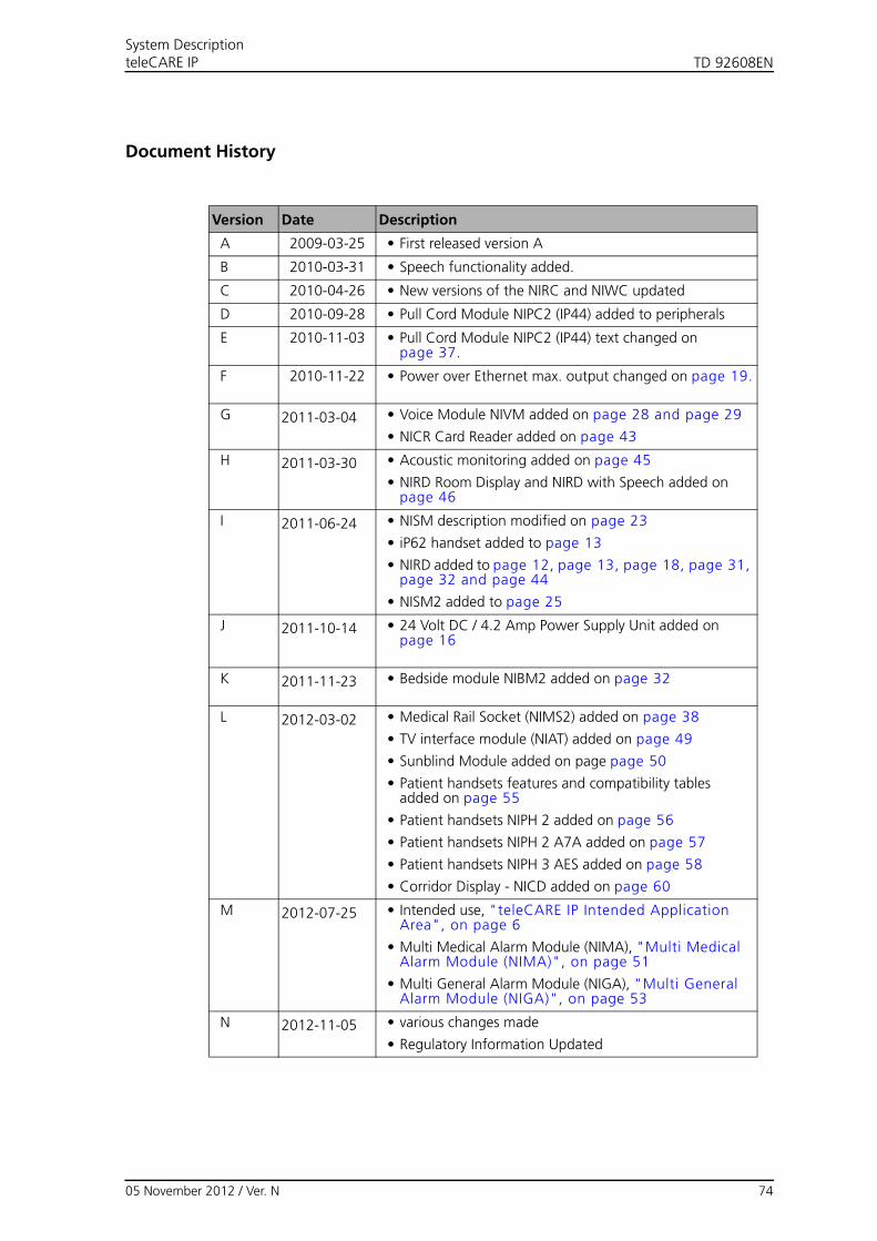
05 November 2012 / Ver. N 74
TD 92608ENSystem DescriptionteleCARE IP
Document History
Version Date Description
A 2009-03-25 • First released version A
B 2010-03-31 • Speech functionality added.
C 2010-04-26 • New versions of the NIRC and NIWC updated
D 2010-09-28 • Pull Cord Module NIPC2 (IP44) added to peripherals
E 2010-11-03 • Pull Cord Module NIPC2 (IP44) text changed on page 37.
F 2010-11-22 • Power over Ethernet max. output changed on page 19.
G 2011-03-04 • Voice Module NIVM added on page 28 and page 29
• NICR Card Reader added on page 43
H 2011-03-30 • Acoustic monitoring added on page 45
• NIRD Room Display and NIRD with Speech added on page 46
I 2011-06-24 • NISM description modified on page 23
• iP62 handset added to page 13
• NIRD added to page 12, page 13, page 18, page 31, page 32 and page 44
• NISM2 added to page 25
J 2011-10-14 • 24 Volt DC / 4.2 Amp Power Supply Unit added on page 16
K 2011-11-23 • Bedside module NIBM2 added on page 32
L 2012-03-02 • Medical Rail Socket (NIMS2) added on page 38
• TV interface module (NIAT) added on page 49
• Sunblind Module added on page page 50
• Patient handsets features and compatibility tablesadded on page 55
• Patient handsets NIPH 2 added on page 56
• Patient handsets NIPH 2 A7A added on page 57
• Patient handsets NIPH 3 AES added on page 58
• Corridor Display - NICD added on page 60
M 2012-07-25 • Intended use, "teleCARE IP Intended Application Area", on page 6
• Multi Medical Alarm Module (NIMA), "Multi Medical Alarm Module (NIMA)", on page 51
• Multi General Alarm Module (NIGA), "Multi General Alarm Module (NIGA)", on page 53
N 2012-11-05 • various changes made
• Regulatory Information Updated