Embed Size (px)
Citation preview
Teleline™Standalone 4-wire HDSL With Span Power model 751239SP Description and Installation Guide925W751042-02E

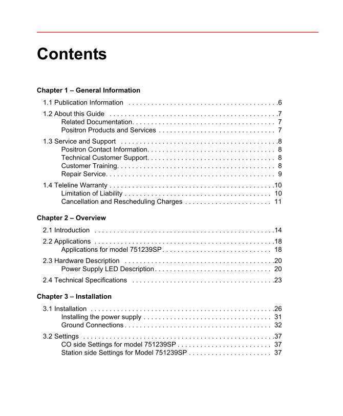
Contents
Chapter 1 – General Information
1.1 Publication Information . . . . . . . . . . . . . . . . . . . . . . . . . . . . . . . . . . . . . . . .61.2 About this Guide . . . . . . . . . . . . . . . . . . . . . . . . . . . . . . . . . . . . . . . . . . . . .7
Related Documentation. . . . . . . . . . . . . . . . . . . . . . . . . . . . . . . . . . . . . . 7Positron Products and Services . . . . . . . . . . . . . . . . . . . . . . . . . . . . . . . 7
1.3 Service and Support . . . . . . . . . . . . . . . . . . . . . . . . . . . . . . . . . . . . . . . . . .8Positron Contact Information. . . . . . . . . . . . . . . . . . . . . . . . . . . . . . . . . . 8Technical Customer Support. . . . . . . . . . . . . . . . . . . . . . . . . . . . . . . . . . 8Customer Training. . . . . . . . . . . . . . . . . . . . . . . . . . . . . . . . . . . . . . . . . . 8Repair Service. . . . . . . . . . . . . . . . . . . . . . . . . . . . . . . . . . . . . . . . . . . . . 9
1.4 Teleline Warranty . . . . . . . . . . . . . . . . . . . . . . . . . . . . . . . . . . . . . . . . . . . .10Limitation of Liability . . . . . . . . . . . . . . . . . . . . . . . . . . . . . . . . . . . . . . . 10Cancellation and Rescheduling Charges . . . . . . . . . . . . . . . . . . . . . . . 11
Chapter 2 – Overview
2.1 Introduction . . . . . . . . . . . . . . . . . . . . . . . . . . . . . . . . . . . . . . . . . . . . . . . .142.2 Applications . . . . . . . . . . . . . . . . . . . . . . . . . . . . . . . . . . . . . . . . . . . . . . . .18
Applications for model 751239SP. . . . . . . . . . . . . . . . . . . . . . . . . . . . . 182.3 Hardware Description . . . . . . . . . . . . . . . . . . . . . . . . . . . . . . . . . . . . . . . .20
Power Supply LED Description . . . . . . . . . . . . . . . . . . . . . . . . . . . . . . . 202.4 Technical Specifications . . . . . . . . . . . . . . . . . . . . . . . . . . . . . . . . . . . . . .23
Chapter 3 – Installation
3.1 Installation . . . . . . . . . . . . . . . . . . . . . . . . . . . . . . . . . . . . . . . . . . . . . . . . .26Installing the power supply . . . . . . . . . . . . . . . . . . . . . . . . . . . . . . . . . . 31Ground Connections . . . . . . . . . . . . . . . . . . . . . . . . . . . . . . . . . . . . . . . 32
3.2 Settings . . . . . . . . . . . . . . . . . . . . . . . . . . . . . . . . . . . . . . . . . . . . . . . . . . .37CO side Settings for model 751239SP . . . . . . . . . . . . . . . . . . . . . . . . . 37Station side Settings for Model 751239SP . . . . . . . . . . . . . . . . . . . . . . 37
Standalone 4-wire HDSL model 751239SP
3.3 Battery replacement procedure . . . . . . . . . . . . . . . . . . . . . . . . . . . . . . . . 40Replacement Batteries . . . . . . . . . . . . . . . . . . . . . . . . . . . . . . . . . . . . . 40Replacement procedure . . . . . . . . . . . . . . . . . . . . . . . . . . . . . . . . . . . . 40
Appendix A – Acronyms
Acronyms . . . . . . . . . . . . . . . . . . . . . . . . . . . . . . . . . . . . . . . . . . . . . . . 44
Chapter 1
General Information
6
Standalone 4-wire HDSL model 751239SP
1.1 Publication Information© 2012 Positron Inc.
Teleline Standalone 4-wire HDSL With Span Power model 751239SP Description and Installation Guide Part number: 925W751042-02E
Publication date: April 12, 2012
Published ByPositron Inc. 5101 Buchan Street, Suite 220 Montreal, Quebec, Canada H4P 2R9 Telephone: US and Canada: 1-888-577-5254International: 1-514-345-2220
TrademarksTeleline is a trademark of Positron Inc.
Product names, other than Positron’s, mentioned herein may be trademarks and/or registered trademarks of their respective companies
Confidentiality NoticeThe information contained in this document is the property of Positron Inc. Except as specifically authorized in writing by Positron Inc., the holder of this document: 1) shall keep all information contained herein confidential and shall protect same in whole or in part from the disclosure and dissemination to all third parties, and 2) shall use same for operating and maintenance purposes only.
Disclaimer NoticeAlthough Positron Inc. has made every effort to ensure the accuracy of the information contained herein, this document is subject to change without notice.
7
About this Guide
1.2 About this GuideThis guide introduces you to the Teleline Standalone 4-wire HDSL (High speed Digital Subscriber Line) With Span Power model 751239SP and its features and applications. This guide was designed to be read from beginning to end.
1.2.1 Related DocumentationThe other guides in the Teleline set are listed below. To order any manuals, please contact your customer service representative.
Teleline System Manual
Teleline System Overview
Teleline Product Guide
1.2.2 Positron Products and ServicesPositron engineers and manufactures high voltage isolation products to protect personnel and telecommunications circuits in high voltage areas that are susceptible to the effects of Ground Potential Rise (GPR).
Positron is the leader in isolation technology with its Teleline wireline products and TeleLite optical fiber wireline isolation/protection product families. Positron provides total flexibility in product configuration – from standalone units protecting a single circuit to high-capacity, multi-shelf High Voltage Interface (HVI) preconfigured systems.
Positron also provides a wide range of consulting, analysis and training services for communications companies and electrical utilities.
Full details and contact information are available at www.PositronPower.com.

8
Standalone 4-wire HDSL model 751239SP
1.3 Service and Support
1.3.1 Positron Contact Information
1.3.2 Technical Customer SupportPositron is committed to providing excellent ongoing technical support to its customers. A team of specialists is always available for telephone consultations or for on-site visits to assist in the maintenance and troubleshooting of Positron equipment.
For pricing information or assistance in the planning, configuration and implementation of the installation of equipment, contact Technical Customer Service.
1.3.3 Customer TrainingFull customer training courses on High Voltage Interface (HVI) are also available. For more information, contact Positron.
General information: Positron Inc.5101 Buchan Street, Suite 220Montreal, Quebec, CanadaH4P 2R9US and Canada: 1-888-577-5254International: 1-514-345-2220Fax: 514-345-2271E-mail: [email protected]: www.PositronPower.com
Customer Service and Repairs:
US and Canada: 1-888-577-5254International: 1-514-345-2220E-mail: [email protected]
9
Service and Support
1.3.4 Repair ServiceAll warranty repairs are performed at no cost. Positron reserves the right to repair or replace any equipment that has been found to be defective.
For information about out-of-warranty repairs, contact Positron’s Repair Department. Due to the varied nature of repairs, no specific turnaround can be guaranteed, but average turnaround time is 20 working days from date of receipt. In emergency situations, special arrangements can be made. All repaired items are warranted for a period of 90 days.
Before returning any items to Positron for repair, warranty repair or replacement, call the Repair department to obtain a Return Material Authorization (RMA) number. Parts returned without RMA numbers cannot be accepted. The RMA number must always be clearly marked on all boxes, crates, and shipping documents. Bulk repairs (more than five items) will require additional processing time, so please take this into consideration when requesting an RMA number.
To accelerate the repair process, whenever possible, include a report detailing the reason for return with the unit(s). Also, please include the name and phone number of a person who can be contacted should our Repair department need further information.
When packing items being returned for repair, please ensure they are properly packed to avoid further damage. TeleLine plug-in cards should never be shipped while installed in a shelf; this will cause damage that can extend the repair period
10
Standalone 4-wire HDSL model 751239SP
1.4 Teleline WarrantySubject to the provisions of this paragraph, Positron warrants that the equipment shall perform in accordance with Positron's specifications. The warranty remains valid for five (5) years from the date of shipment. The warranty fully covers workmanship, materials and labor. Positron shall, at its sole discretion, repair or replace the problem unit.
Freight costs to ship defective equipment to Positron are borne by the Customer, with return of replaced or repaired equipment to be at Positron's expense.
1.4.1 Limitation of Liability Subject to anything to the contrary contained herein, Positron's sole obligation and liability and the customer's sole remedy for Positron's negligence, breach of warranty, breach of contract or for any other liability in any way connected with or arising out of, the equipment or any services performed by Positron shall be as follows:
In all situations involving performance or non-performance of the equipment or any component thereof, the customer's sole remedy shall be, at Positron's option, the repair or replacement of the equipment or said component.
For any other claim in any other way related to the subject matter of any order under, the customer shall be entitled to recover actual and direct damages; provided that Positron's liability for damages for any cause whatsoever, and regardless of the form of the action, whether in contract or in tort (including negligence), shall be limited to the value of the order.
Positron shall not be obligated to repair or replace any item of the equipment which has been repaired by others, abused or improperly handled, improperly stored, altered or used with third party material or equipment, which material, or equipment may be defective, of poor quality or incompatible with the equipment supplied by Positron, and Positron shall not be obligated to repair or replace any component of the equipment which has not been installed according to Positron specifications.
IN NO EVENT SHALL POSITRON BE LIABLE FOR ANY INDIRECT, INCIDENTAL, SPECIAL, CONSEQUENTIAL, PUNITIVE, EXEMPLARY OR SIMILAR OR ADDITIONAL DAMAGES INCURRED OR SUFFERED INCLUDING

11
Teleline Warranty
LOSS OF PROFITS, LOSS OF REVENUES, LOSS OF DATA, LOSS OF BUSINESS INFORMATION, LOSS OF GOODWILL, LOSS OF EXPECTED SAVINGS OR BUSINESS INTERRUPTION ARISING OUT OF OR IN CONNECTION WITH THE EQUIPMENT, A PURCHASE ORDER, SUPPLIES, MAINTENANCE SERVICES OR OTHER SERVICES FURNISHED HEREUNDER, EVEN IF POSITRON HAS BEEN ADVISED OR IS AWARE OF THE POSSIBILITY OF SUCH DAMAGES.
EXCEPT AS EXPRESSLY SET FORTH IN THIS AGREEMENT, POSITRON DISCLAIMS ANY FURTHER CONDITIONS, REPRESENTATIONS OR WARRANTIES, WHETHER WRITTEN OR ORAL, EXPRESSED OR IMPLIED, INCLUDING THE CONDITIONS AND WARRANTIES OF MERCHANTABILITY, MERCHANTABLE QUALITY, FITNESS FOR A PARTICULAR PURPOSE, TITLE, PERFORMANCE AND THOSE ARISING FROM STATUTE, TO THE EXTENT PERMITTED BY LAW. POSITRON DOES NOT WARRANT THAT THE SYSTEM WILL OPERATE WITHOUT INTERRUPTION OR THAT IT WILL BE ERROR FREE.
1.4.2 Cancellation and Rescheduling ChargesShould the customer cancel, prior to shipment, any part of an order, the customer agrees to pay to Positron cancellation charges, not as a penalty, which shall total all expenses, including labor expenses, incurred by Positron prior to said cancellation. Equipment that has been specially developed for the customer's specific applications shall not be subject to cancellation. Cancellation or rescheduling is not permissible after shipment of the System.


Chapter 2
Overview
14
Standalone 4-wire HDSL model 751239SP
2.1 IntroductionThe Teleline Standalone 4-wire HDSL with Span Power model 751239SPprovides high-voltage isolation between one, 4-wire Remote Terminal Unit (HTU-R) located inside the substation, and an HDSL Central Office (CO) Terminal Unit (HTU-C).
The Standalone 4-wire HDSL Classic unit model 751239 has been manufacture discontinued. Positron will continue to support field deployments of this unit through the warranty period.
A standalone unit consists of an isolator card mounted inside a compact enclosure. The enclosure is molded from fiberglass, making it a lightweight, flame-retardant container of high dielectric strength. Its fiberglass body limits the possibility of many kinds of infiltration while providing reliable isolation from external ground potentials.
The standalone unit is shipped with an installation kit that includes a 12-conductor cable for connection to the CO incoming cable, and mounting hardware.
Features for model 751239SP include the following:
Isolation of 50 kVrms (70 kV peak) while maintaining full communication between terminals.
Communication maintained across the gap by isolation transformers that provide low-loss low-distortion transmission.
Operates from -48 Vdc supplied by an integrated, multi-input power supply
When operating from a -24 Vdc source, the power supply is polarity sensitive
When operating from 42 Vdc to 130 Vdc, or from a 120 Vac source, the power supply is not polarity sensitive.
Battery backup (when Power Supply Piggyback 220W000021-401 is installed.
Jumper settings allow configuring the unit to provide a simplex sealing current or a loop sealing return path on the CO side.
Model 751239SP will provide a -120 Vdc simplex span voltage to power the HTU-R.
NOTE
15
Introduction
Enclosures resist the infiltration of dust, mist, and water from sprinklers
A jumper setting allows loop or simplex span powering of the HTU-R.
A loss of 610 m (2,000 ft.) is introduced in the span for each 751239SP card installed.
For illustrations of the Model 751239SP:
Front and side views, see Figure 1 below.
Major component layout, see Figure 2 on page 16.
Figure 1: Model 751239SP enclosure
NOTE

16
Standalone 4-wire HDSL model 751239SP
Figure 2: Model 751239SP Component Layout (only major components shown, without power supply)
The layout shown above illustrates the default jumper settings for model 751239SP.
NOTE
17
Introduction
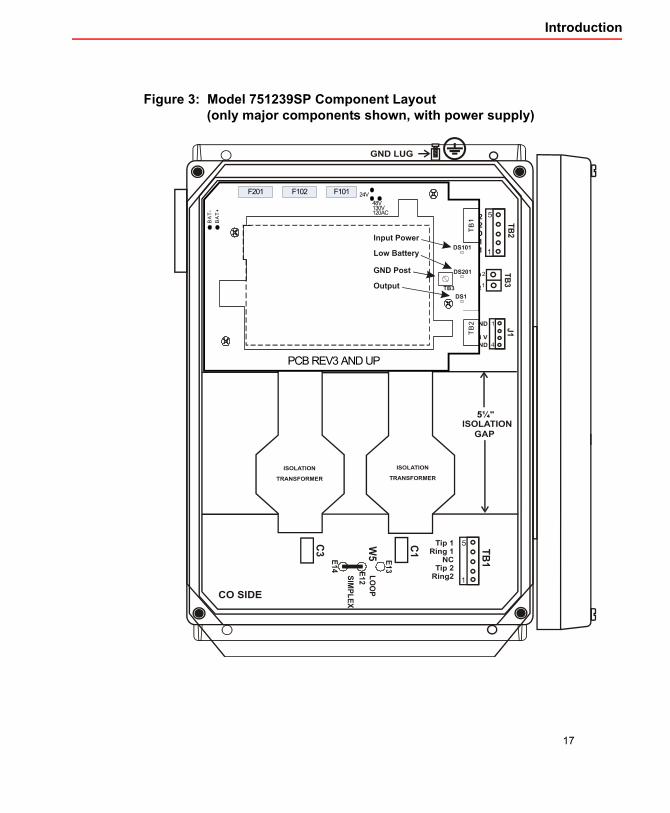
Figure 3: Model 751239SP Component Layout (only major components shown, with power supply)
18
Standalone 4-wire HDSL model 751239SP
2.2 Applications
2.2.1 Applications for model 751239SPThe model 751239SP can be deployed in installations that use:
HDSL Classic (2B1Q), one HDSL2, two HDSL2, and one HDSL4 with support of -129 Vdc & -190 Vdc on the loop. For supported span distance, see Table 1 below.
Data transmission lines within the passband of the card (1.544 Mb/s).
Station side span powered HTU-R.
Station side locally powered HTU-R.
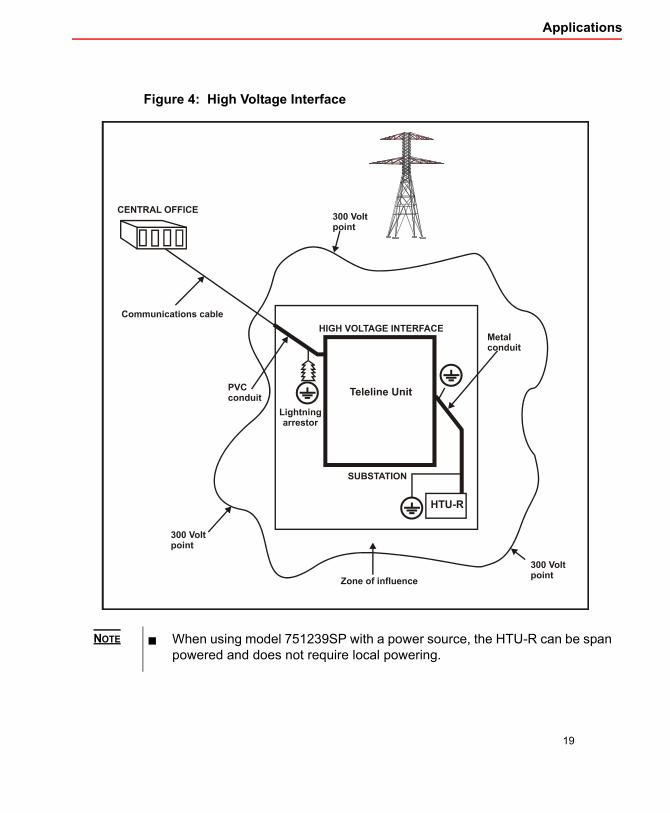
For an illustration of how the unit is used as part of the high voltage interface, see Figure 4 on page 19.
The model 751239SP can provide power to the Station side span for a span powered HTU-R.
For the unit to span-power an HTU-R at 120 Vdc, a power supply (24 Vdc, 48 Vdc to 130 Vdc or 120 Vac) is needed.
Table 1:
Application Local Power ModeHDSL Classic (2B1Q) 610m (2,000 ft)HDSL2 610m (2,000 ft)Two HDSL2 Half of the total span distanceHDSL4 610m (2,000 ft)
The total span is the distance between the CO and the Station side equipment.
Span Distance Reductions for model 751239SP
NOTE
NOTE
19
Applications
Figure 4: High Voltage Interface
When using model 751239SP with a power source, the HTU-R can be span powered and does not require local powering.
NOTE
20
Standalone 4-wire HDSL model 751239SP
2.3 Hardware DescriptionThe Model 751239SP contains a built-in 4-wire HDSL card. Each isolation card has two sides:
The Station side is located on the upper portion of the card.
The CO side is located on the lower portion of the card.
The isolation transformers separate the Station side from the CO side, creating a 13.2 cm (5¼”) isolation gap.
The center taps of the two transformers are shorted together on the PCB to allow the simplex sealing loop current to flow across the pairs.
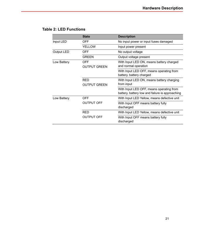
2.3.1 Power Supply LED DescriptionThe Power Supply piggyback has three LEDs to facilitate troubleshooting of the unit. The LEDs are shown in Figure 3 on page 17. For a description of the LEDs see Figure 2 on page 21.
21
Hardware Description
Table 2:
State DescriptionInput LED OFF No input power or input fuses damaged
YELLOW Input power presentOutput LED OFF No output voltage
GREEN Output voltage presentLow Battery OFF
OUTPUT GREENWith Input LED ON, means battery charged and normal operationWith Input LED OFF, means operating from battery, battery charged
REDOUTPUT GREEN
With Input LED ON, means battery charging from inputWith Input LED OFF, means operating from battery, battery low and failure is approaching
Low Battery OFFOUTPUT OFF
With Input LED Yellow, means defective unitWith Input OFF means battery fully discharged
REDOUTPUT OFF
With Input LED Yellow, means defective unitWith Input OFF means battery fully discharged
LED Functions
22
Standalone 4-wire HDSL model 751239SP
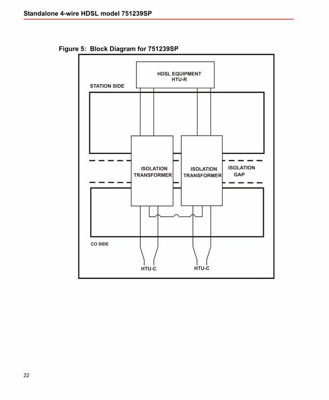
Figure 5: Block Diagram for 751239SP
23
Technical Specifications
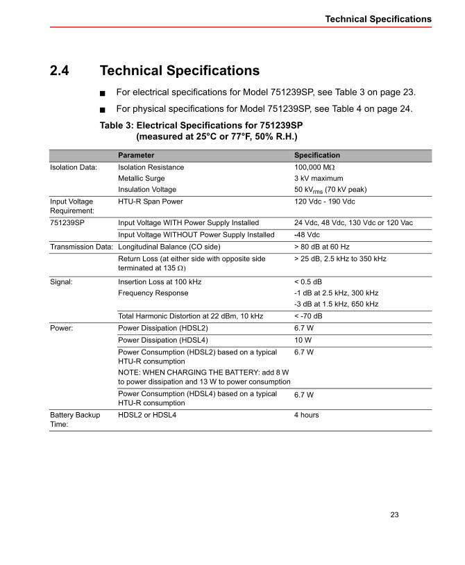
2.4 Technical SpecificationsFor electrical specifications for Model 751239SP, see Table 3 on page 23.
For physical specifications for Model 751239SP, see Table 4 on page 24.
Table 3: Electrical Specifications for 751239SP (measured at 25°C or 77°F, 50% R.H.)
Parameter SpecificationIsolation Data: Isolation Resistance
Metallic SurgeInsulation Voltage
100,000 MΩ3 kV maximum50 kVrms (70 kV peak)
Input Voltage Requirement:
HTU-R Span Power 120 Vdc - 190 Vdc
751239SP Input Voltage WITH Power Supply Installed 24 Vdc, 48 Vdc, 130 Vdc or 120 VacInput Voltage WITHOUT Power Supply Installed -48 Vdc
Transmission Data: Longitudinal Balance (CO side) > 80 dB at 60 HzReturn Loss (at either side with opposite side terminated at 135 Ω)
> 25 dB, 2.5 kHz to 350 kHz
Signal: Insertion Loss at 100 kHzFrequency Response
< 0.5 dB-1 dB at 2.5 kHz, 300 kHz-3 dB at 1.5 kHz, 650 kHz
Total Harmonic Distortion at 22 dBm, 10 kHz < -70 dBPower: Power Dissipation (HDSL2) 6.7 W
Power Dissipation (HDSL4) 10 WPower Consumption (HDSL2) based on a typical HTU-R consumptionNOTE: WHEN CHARGING THE BATTERY: add 8 W to power dissipation and 13 W to power consumption
6.7 W
Power Consumption (HDSL4) based on a typical HTU-R consumption
6.7 W
Battery Backup Time:
HDSL2 or HDSL4 4 hours
24
Standalone 4-wire HDSL model 751239SP
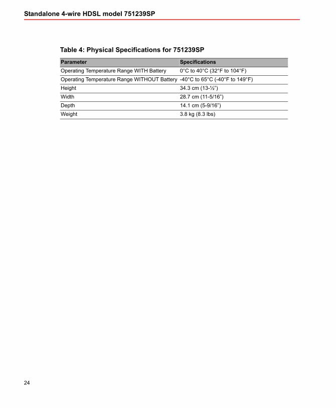
Table 4: Physical Specifications for 751239SP
Parameter SpecificationsOperating Temperature Range WITH Battery 0°C to 40°C (32°F to 104°F)Operating Temperature Range WITHOUT Battery -40°C to 65°C (-40°F to 149°F)Height 34.3 cm (13-½”)Width 28.7 cm (11-5/16”)Depth 14.1 cm (5-9/16”)Weight 3.8 kg (8.3 lbs)
Chapter 3
Installation
26
Standalone 4-wire HDSL model 751239SP
3.1 Installation
The Model 751239SP is used when the number of lines to be isolated does not justify the installation of a shelf. It will isolate one 4-wire HDSL circuit.
CAUTION Stand on a thick rubber mat and wear rubber gloves during the installation procedure. Perform these procedures on a clear dry day when a Ground Potential Rise (GPR) or Transients are less likely to occur.
When wiring a unit, keep the Station and CO cables at least 15 cm (6”) apart to prevent an electric arc between them in the event of, damage to, or degradation of cable insulation.
ATTENTIONELECTROSTATIC
SENSITIVEDEVICES
HANDLE ONLY AT STATICSAFE WORKSTATION
INCORRECT HANDLING MAY VOID WARRANTY
These procedures must be followed when handling an electrostatic sensitive device.
• A grounded wrist strap must be worn at all times during installation.• When unpacking, place the antistatic bag containing the device on an
electrostatic discharge (ESD) safe surface. An ESD safe surface is a conductive surface connected directly to an earth ground.
• When moving, carry the device in an ESD safe container or the antistaticbag, provided with the device.
ESD Precaution

27
Installation
Figure 6: Layout for model 751239SP
Station end HDSL carrier terminal equipment CANNOT be powered from the CO line side cable pairs using this type of card.
An internal connection of the board can loop or simplex the current back to the CO side CT of Loop 1 and Loop 2.
Loop 1 and Loop 2 can be interchanged.
For an illustration of a setup with system span-powered for model 751239SP, see Figure 7 on page 28.
NOTE

28
Standalone 4-wire HDSL model 751239SP
Figure 7: Setup for Model 751239SP Station Side Span Power
Sealing Current mode: between pair 1 (GND) and pair 2 (-120 Vdc)
Loop Current mode: between Tip X (GND) and Ring X (-120 Vdc)
TB2 and TB3 are located on the Station side backplane.
NOTE
29
Installation
To Install the model 751239SP
1. Verify that you have the following customer supplied tools and hardware, which are required to install the unit:
Station cable
Center punch
Electric drill with a 5/32” diameter bit
7/16” hex wrench
1/8” and 1/4” common blade screwdrivers
Phillips screwdriver
2.5 cm (1”) thick plywood backboard with appropriate mounting hardware
Cable clamps and mounting hardware for routing cables exterior to the shelf (quantity determined by the cable lengths involved).
2. Unpack the model 751239SP, the Power Supply Piggyback (220W000021-401) and installation hardware from the protective box.
3. Check the contents of your model 751239SP kit. For kit contents, see Table 5 on page 30.
30
Standalone 4-wire HDSL model 751239SP
Table 5: Installation Kit Content for Model 751239SP
Description Qty. Part NumberCABLE, PWR SUP, 3 COND, 6 FT, GRAY 1 207-990000-020CABLE, SHLD, SEALPIC, 6-PAIR, #22AWG 10 foot 207-990000-138CABLE, 3X#18AWG, 300V, 60C, SJT PVC, BLACK 8 foot 207W000007-001CON, CORD GRIP, HUB:1/2”, BLK 1 230-990400-036CON, CORD GRIP, HUB:1/2”, BLK 1 230-990400-037CON, CORD GRIP, HUB:1/2”, BLK 1 230-990400-038INSTRUCTION, STATION RELIEF:A 1 241-010016-001SCREW, HEX W/WASHR, #14A X 1"L 4 724-990000-011FASTENER, CABLE, NYL,.75” DIA. 5 706-990000-010FUSE, 2A, 250VAC, FAST-ACTING, 5X20mm (Input) 2 294W000010-001FUSE, 6.3A, 250VAC, SLO-BLO, 5X20mm (Battery) 1 294W000050-001
4. Confirm that the isolation unit is a model 751239SP unit by identifying the name located inside the cover, and the model number printed on a metallic label on the top right-hand portion of the unit.
5. Unfasten the unit’s cover.
6. Insert jumpers according to your application. See section 3.2 on page 37 for possible CO and Station side jumper settings.
The strain reliefs supplied each have a cable entry diameter appropriate for one of the three cables used in this installation. The CO cable strain relief is the largest, accommodating cable diameters from 0.40” to 0.56”. (All measurements are outside cable diameters)
The Station cable strain relief accepts cable diameters from 0.125” to 0.275”.
The Power cable strain relief accommodates cables with diameters of 0.25” to 0.40”.
7. Affix the three strain reliefs to the unit.
31
Installation
3.1.1 Installing the power supplyThe Power Supply Piggyback board is not fastened to the main isolation card prior to shipment and requires installation.
8. If the unit is to be powered from 24 Vdc, then set the input jumper (W101) located near F101 on the Power Supply piggyback, to E104-E105. If the unit is powered from 48 Vdc, 130 Vdc or 120 Vac, jumper W101 should be between E105 - E106 (see Figure 3 on page 17).
If unit is powered from 48 Vdc, 130 Vdc or 120 Vac, it is NOT polarity sensitive. If the unit is powered from 24 Vdc, the unit IS polarity sensitive (see Table 6 on page 34 for proper polarity).
9. Run the HDSL (Station side) cable through the strain relief nearest the bottom of the enclosure to connector TB-2. (see Figure 2 on page 16)
10. Remove the screws and lock washers from the standoff (spacers) mounted on the Station side circuit board.
11. Position the power supply board onto the spacers and align the board holes with the spacers. (See Figure 3 on page 17)
12. Secure the power supply to the standoffs using the four screws and lock washers.
13. Fasten the 1” thick plywood backboard to the wall.
14. Position the enclosure on the backboard with the air vent facing down or to the left, and mount it to the backboard using the four screws supplied.
NOTE

32
Standalone 4-wire HDSL model 751239SP
3.1.2 Ground Connections
15. Connect the ground cable inside the unit to connector TB-3 on the power supply. (See Figure 3 on page 17)
16. Connect the ground lug on the outside of the unit to Station ground using a #6 AWG stranded wire.
17. Using the supplied cable connect the power supply’s output connector TB-2 to J1 on the main isolation card. Refer to Figure 9 on page 39.
To prevent discharge during shipping, the power supply unit is shipped with both leads of the battery disconnected.
18. Route the power to the unit using one of the power cables provided with the kit. If powering the unit from 120 Vac, use the AC cable (with the prong plug) and if powering from AC (24 Vdc, 48 Vdc or 130 Vdc) use the unterminated cable. MAKE SURE YOU HAVE SET THE INPUT JUMPER CORRECTLY (see step 8) Refer to Table 6 on page 34 for connections.
The Station side of the enclosure is the side connected to the external ground lug. Mount the unit with the air vent facing the bottom or left.
19. Make sure that there are no excess wires dangling into the 14 cm (5-1/4”) isolation gap between the Station and CO side circuits inside the enclosure. If necessary, bundle the individual cable conductors with tie wraps to prevent them intruding into the isolation gap.
20. Route the Black PIC CO cable, and the Grey Station cable through the strain reliefs, allowing a length of 13 cm (5”) per cable for the internal connections to the terminal blocks. Cut the excess wire once the exact internal length is established, and tighten the strain reliefs.
CAUTION The equipment ground must be connected before any other connection is made to the unit.
Installations must conform to local electrical code.
All units must be permanently connected to earth.
There shall be no switching or disconnecting devices in the earthed circuit conductor between the unit and the earthing electrode conductor.
NOTE
33
Installation
21. Strip back the outer jacket of each cable to a length of 2.5 cm (1”). Strip the inner insulating jacket of each conductor to a length of 3.2 mm (1/8)”. Connect these stripped conductors to the designated terminal locations.
To locate connectors, see Figure 2 on page 16.
For a listing of terminal block connections, see Table 6 on page 34.
34
Standalone 4-wire HDSL model 751239SP
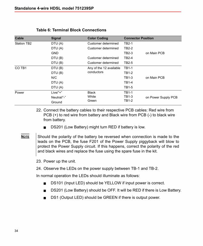
Table 6: Terminal Block Connections
Cable Signal Color Coding Connector PositionStation TB2 DTU (A)
DTU (A)GNDDTU (B)DTU (B)
Customer determinedCustomer determined
Customer determinedCustomer determined
TB2-1TB2-2TB2-3TB2-4TB2-5
on Main PCB
CO TB1 DTU (B)DTU (B)N/CDTU (A)DTU (A)
Any of the 12 available conductors
TB1-1TB1-2TB1-3TB1-4TB1-5
on Main PCB
Power Live/”+”Neutral/”-”Ground
Black White Green
TB1-1 TB1-3 TB1-2
on Power Supply PCB
22. Connect the battery cables to their respective PCB cables: Red wire from PCB (+) to red wire from battery and Black wire from PCB (-) to black wire from battery.
DS201 (Low Battery) might turn RED if battery is low.
Should the polarity of the battery be reversed when connection is made to the leads on the PCB, the fuse F201 of the Power Supply piggyback will blow to protect the Power Supply circuit. If this happens, correct the polarity of the red and black wires and replace the fuse using the spare fuse in the kit.
23. Power up the unit.
24. Observe the LEDs on the power supply between TB-1 and TB-2.
In normal operation the LEDs should illuminate as follows:
DS101 (Input LED) should be YELLOW if input power is correct.
DS201 (Low Battery) should be OFF. It will be RED if there is Low Battery.
DS1 (Output LED) should be GREEN if there is output power.
NOTE

35
Installation
25. Verify the installation by establishing communication.
The layout shown in Figure 2 on page 16 illustrates the default jumper settings for model 751239SP.
26. Close and secure the enclosure cover with captive screws.
Keep the Station and CO cables outside the unit at least 15 cm (6”) apart to prevent an electric arc between them in the event of, damage to, or degradation of cable insulation.
NOTE
CAUTION

36
Standalone 4-wire HDSL model 751239SP
Figure 8: Power Supply connections and jumper settings
37
Settings
3.2 Settings
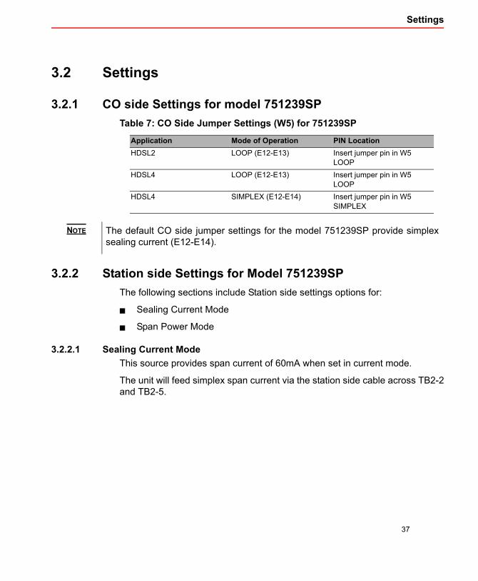
3.2.1 CO side Settings for model 751239SPTable 7: CO Side Jumper Settings (W5) for
Application Mode of Operation PIN LocationHDSL2 LOOP (E12-E13) Insert jumper pin in W5
LOOPHDSL4 LOOP (E12-E13) Insert jumper pin in W5
LOOPHDSL4 SIMPLEX (E12-E14) Insert jumper pin in W5
SIMPLEX
The default CO side jumper settings for the model 751239SP provide simplex sealing current (E12-E14).
751239SP
3.2.2 Station side Settings for Model 751239SPThe following sections include Station side settings options for:
Sealing Current Mode
Span Power Mode
3.2.2.1 Sealing Current ModeThis source provides span current of 60mA when set in current mode.
The unit will feed simplex span current via the station side cable across TB2-2 and TB2-5.
NOTE
38
Standalone 4-wire HDSL model 751239SP
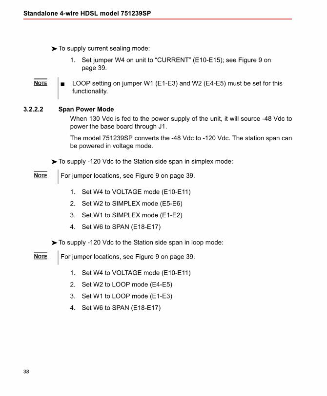
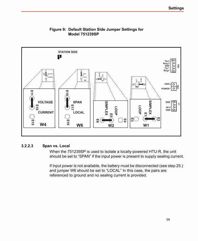
To supply current sealing mode:
1. Set jumper W4 on unit to “CURRENT” (E10-E15); see Figure 9 on page 39.
LOOP setting on jumper W1 (E1-E3) and W2 (E4-E5) must be set for this functionality.
3.2.2.2 Span Power ModeWhen 130 Vdc is fed to the power supply of the unit, it will source -48 Vdc to power the base board through J1.
The model 751239SP converts the -48 Vdc to -120 Vdc. The station span can be powered in voltage mode.
To supply -120 Vdc to the Station side span in simplex mode:
For jumper locations, see Figure 9 on page 39.
1. Set W4 to VOLTAGE mode (E10-E11)
2. Set W2 to SIMPLEX mode (E5-E6)
3. Set W1 to SIMPLEX mode (E1-E2)
4. Set W6 to SPAN (E18-E17)
To supply -120 Vdc to the Station side span in loop mode:
For jumper locations, see Figure 9 on page 39.
1. Set W4 to VOLTAGE mode (E10-E11)
2. Set W2 to LOOP mode (E4-E5)
3. Set W1 to LOOP mode (E1-E3)
4. Set W6 to SPAN (E18-E17)
NOTE
NOTE
NOTE
39
Settings
Figure 9: Default Station Side Jumper Settings for Model 751239SP
3.2.2.3 Span vs. LocalWhen the 751239SP is used to isolate a locally-powered HTU-R, the unit should be set to “SPAN” if the input power is present to supply sealing current.
If input power is not available, the battery must be disconnected (see step 25.) and jumper W6 should be set to “LOCAL” In this case, the pairs are referenced to ground and no sealing current is provided.

40
Standalone 4-wire HDSL model 751239SP
3.3 Battery replacement procedureAfter its expected life of 5 years, the battery will need to be replaced.
3.3.1 Replacement BatteriesThe battery has to be UL approved with a UL94V rated casing.The following sources are approved to be used as replacement:
Power Sonic #PS1221S
Enersys #NP2-12FR
Yuasa #NP2-12
MK Battery #ES2-12SLM
3.3.2 Replacement procedure1. Disconnect input power to the unit.
2. Disconnect the output cable of the power supply from the telephone card underneath.
3. Disconnect the black and red wires of the battery from the black and red wires of the PCB.
4. Remove the screws holding the battery holding bracket (see Figure 3 on page 17).
5. Remove the battery from the power supply.
6. Move the wires from the old battery to the new battery. Be sure to installed the black wire to the “-” and the red wire to the “+” of the new battery.
7. Install the new battery on the power supply and back the battery holding bracket using the screws.
8. Connect the output cable of the power supply to the connector of the telephone card underneath.
41
Battery replacement procedure
9. Connect the red wire of the battery to the red wire of the power supply and the black wire from the battery to the red wire from the PCB.
Should the polarity of the battery be reversed when connection is made to the leads on the PCB, the fuse F201 of the Power Supply piggyback will blow to protect the Power Supply circuit. If this happens, correct the polarity of the red and black wires and replace the fuse using the spare fuse in the kit.
10. Reconnect the input power to the unit.
The new battery might be partially discharged when you install it, allow it to charge for a couple of hours before verifying the LED statuses.
11. Use Table 2 on page 21 to verify the LEDs statuses.
NOTE
NOTE


Appendix A
Acronyms
Central Office
Center Tap
Data Terminal Unit
Ground
Ground Potential Rise
HDSL4 Terminal Unit - Central Office
High-speed Digital Subscriber Line
HDSL Terminal Unit - Remote user
High Voltage Interface
Printed Circuit Board
Remote Termination Unit
Return Material Authorization
Remote
Receive
Span Power
Transmit
44
Standalone 4-wire HDSL model 751239SP
Acronyms
CO
CT
DTU
GND
GPR
H4TU-C
HDSL
HTU-R
HVI
PCB
PIC
RTU
RMA
RMT
RX
SP
TX