Embed Size (px)
Citation preview
7/26/2019 Television and video engineering
http://slidepdf.com/reader/full/television-and-video-engineering 1/42
TELEVISION AND VIDEO ENGINEERING
UNIT - I
FUNDAMENTALS OF TELEVISION
7/26/2019 Television and video engineering
http://slidepdf.com/reader/full/television-and-video-engineering 2/42
CONTENTS
1. Introduction
1.1 Televiion S!te" And Sc#nnin$ %rinci&le
1.1.1 Sound Transmission
1.1.2 Picture Transmission
1.' Sc#nnin$ %roce
1.2.1 Horizontal Scanning
1.2.2 Vertical Scanning
1.( Video Si$n#l
1.) C*#r#cteritic O+ ,u"#n E!e
1. ri$*tne %erce&tion And %*oto"etric /u#litie
1.5.1 Brightness Perception
1.5.2 Photometric Measurements
1.0 A&ect R#tio And Rect#n$ul#r Sc#nnin$
1.6.1 Aspect atio
1.6.2 Rectangular Scanning
1. %eritence o+ Viion And Flic2er
1.!.1 Persistence "# Vision
1.!.2 $lic%er
1.3 Vertic#l Reolution
1.4 5ell F#ctor
7/26/2019 Television and video engineering
http://slidepdf.com/reader/full/television-and-video-engineering 3/42
1.10 Horizontal Resolution
1.11 Video #nd6idt*
1.12 Interlaced Scanning
1.1( C#"er# Tu7e
1.1) C#"er# Lene
1.1).1 Len Foc#l Len$t*
1.1&.2 Angle o# Vie'
1.1 Auto+ocu S!te"
1.10 C#"er# %ic2 U& Device
1.1 I"#$e Ort*icon
1.1!.1 (ntroduction
1.1!.2 "peration
1.1!.) (mage Section
1.1!.& Scanning Section
1.1!.5 *lectron Multiplier
1.13 Vidicon
1.1+.1 (ntroduction
1.18.2 Operation
1.1+.) ,harge (mage
1.1+.& Storage Action
1.1+.5 Signal ,urrent
7/26/2019 Television and video engineering
http://slidepdf.com/reader/full/television-and-video-engineering 4/42
1.1+.6 -ight Trans#er ,haracteristics
1.14 %lu"7icon
1.1.1 (ntroduction
1.1.2 "peration
1.1.) -ight Trans#er ,haracteristics
1.'8 Silicon Diode Arr#! Vidicon
1.20.1 Introduction
1.2/.2 "peration
1.2/.) Scanning And "peration
1.'1 CCD Solid St#te I"#$e Sc#nner
1.'' Co"&#rion O+ C#"er# Tu7e
1.'( C#"er# Tu7e De+lection Unit
1.') Video %rocein$ O+ C#"er# Si$n#l
1.' Colour Televiion Si$n#l And S!te"
1.25.1 ,olour T0 Signals
1.25.2 ,olour T0 Sstem
TEC,NICAL TERMS
1. Geo"etric +or" 9 $rame size size adopted in TV sstems.
2. R#ter 9 ectangular area o# the picture tue screen on ,T scanned the electron
eam as it is de#lected horizontall and 0erticall.
). A&ect R#tio 3 4idth o# #rame Height o# #rame
&. Sc#nnin$ 3 The process in 'hich the electron eam is made to mo0e le#t to right and
top to ottom to con0ert all the piels into electrical signals at a 0er #ast rate.
5. ,ori:ont#l c#nnin$ 3 Process in 'hich the electron eam is made to mo0e le#t to
right and again right to le#t on the picture.
7/26/2019 Television and video engineering
http://slidepdf.com/reader/full/television-and-video-engineering 5/42
6. %ro$reive c#nnin$ 3 Scanning oth 0ertical and horizontal ta%es place at the same
time.
!. Reolvin$ c#ilit! 3 Ailit o# ee to see the alternate lac% and 'hite ars
distinctl 'ithout an di##icult.
+. %icture reolution 3 Ailit o# image reproducing sstem to resol0e the #iner details.. Piels 3 Picture elements 7 The elementar areas into 'hich picture details ma e
ro%en up.
1/. Monoc*ro"e &icture 3 Blac% 8 'hite picture.
11. C#"er# tu7e 9 9e0ice used to con0ert optical in#ormation into corresponding
electrical signal.
12. C*ro"# i$n#l 9 ,olor signal.
1). ; i$n#l 3 -uminance signal
1&. Color 7urt 3 Sample :+ 7 1/ ccles; o# color sucarrier.
15. Contr#t r#tio 3 Bma Bmin. 4here Bma is maimum luminance and Bmin is
minimum luminance.
16. ,ori:ont#l reolution 3 Ailit to resol0e and reproduce #ine picture details and
maimum numer o# piels along the horizontal scanning line.
1!. Vertic#l Reolution 3 The ailit to resol0e and reproduce #iner details o# picture in
0ertical direction.
1+. 5ell +#ctor 3 esolution $actor.
1. Interl#ced error 3 *rrors that occur due to the time di##erence in starting scanning the
second #ield #rom the usual )2microsecond point.
2/. D#r2 current 3 ,urrent produced 'hen there is no light #alling on the camera tue.
UNIT-1 FUNDAMENTALS OF TELEVISION
1.INTRODUCTION
Tele0ision means <to see #rom a distance=. The desire in man to do so has een there
#or ages. (n the earl ears o# the t'entieth centur man scientists eperimented 'ith the
idea o# using selenium photosensiti0e cells #or con0erting light #rom pictures into electrical
signals and transmitting them through 'ires.
The #irst demonstration o# actual tele0ision 'as gi0en >.-. Baird in ?@ and ,.$.
>en%ins in ?SA around 12! using the techniue o# mechanical scanning emploing
rotating discs. Ho'e0er the real rea%through occurred 'ith the in0ention o# the cathode ra
7/26/2019 Television and video engineering
http://slidepdf.com/reader/full/television-and-video-engineering 6/42
tue and the success o# V.@. C'or%in o# the ?SA in per#ecting the #irst camera tue :the
iconoscope; ased on the storage principle. B 1)/ electromagnetic scanning o# oth
camera and picture tues and other ancillar circuits such as #or eam de#lection 0ideo
ampli#ication etc. 'ere de0eloped.
Though tele0ision roadcast started in 1)5 'orld political de0elopments and the
second 'orld 'ar slo'ed do'n the progress o# tele0ision. 4ith the end o# the 'ar tele0ision
rapidl gre' into a popular medium #or dispersion o# ne's and mass entertainment.
The three di##erent standards o# lac% and 'hite tele0ision ha0e resulted in the
de0elopment o# three di##erent sstems o# colour tele0ision respecti0el compatile 'ith the
three monochrome sstems.
The original colour sstem 'as that adopted the ?SA in 15) on the
recommendations o# its Dational Tele0ision Sstems ,ommittee and hence called the DTS,
sstem. The other t'o colour sstems7PA- and S*,AM are later modi#ications o# the DTS,
sstem 'ith minor impro0ements to con#orm to the other t'o monochrome standards.
1.1 TELEVISION S;STEM AND SCANNING %RINCI%LES
A tele0ision sstem is a ,anadian term #or a group o# tele0ision stations 'hich share
common o'nership randing and programming ut are not legall considered a #ulltele0ision net'or% . Sstems ma e in#ormall re#erred to as net'or%s some people ut
are not true net'or%s under current ,anadian roadcasting regulations.
Sstems are di##erentiated #rom net'or%s primaril their less etensi0e ser0ice area
'hile a net'or% 'ill ser0e most ,anadian roadcast mar%ets in some #orm a sstem 'ill
tpicall ser0e onl a #e' mar%ets. As 'ell a sstem ma or ma not o##er some classes o#
programming such as a national ne'scast 'hich are tpicall pro0ided a net'or%.
Tele0ision sstems should not e con#used 'ith t'instic%s although some indi0idual
stations might e part o# oth tpes o# operations simultaneousl.
7/26/2019 Television and video engineering
http://slidepdf.com/reader/full/television-and-video-engineering 7/42
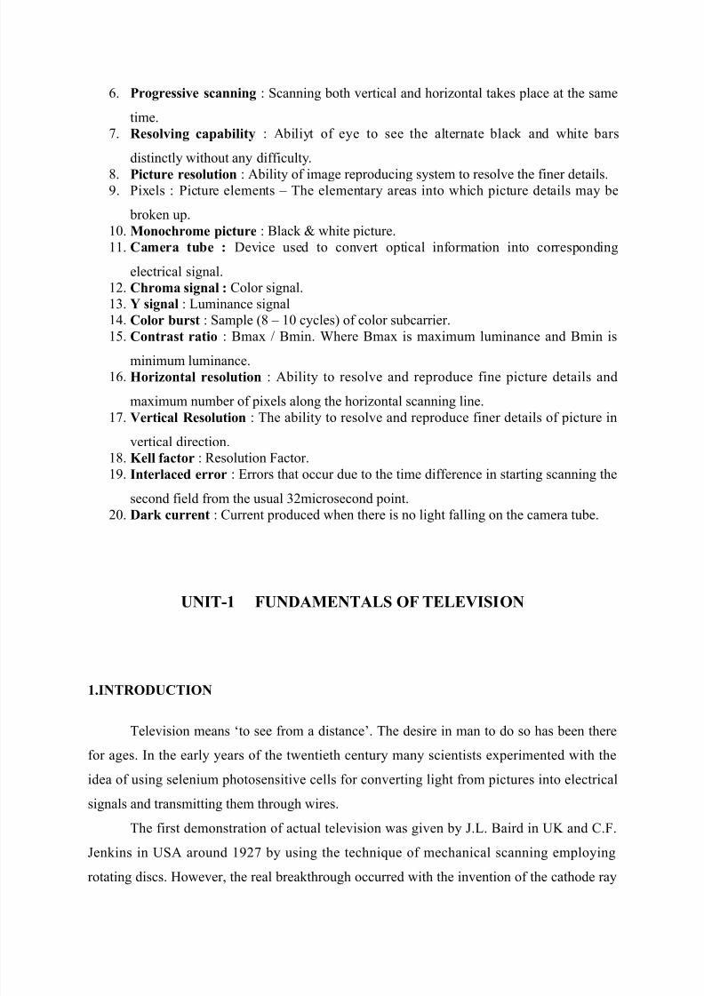
Fi$ 1.1 #ic Monoc*ro"e TV Tr#n"itter
1.1.1 Sound Tr#n"iion
The microphone con0erts the sound associated 'ith the picture eing tele0ised into
proportionate electrical signal 'hich is normall a 0oltage. This electrical output regardless
o# the compleit o# its 'a0e#orm is a single 0alued #unction o# time and so needs a single
channel #or its transmission. The audio signal #rom the microphone a#ter ampli#ication is
#reuenc modulated emploing the assigned carrier #reuenc. (n $M the amplitude o# the
carrier signal is held constant 'hereas its #reuenc is 0aried in accordance 'ith amplitude
0ariations o# the modulating signal. As sho'n in $ig. 1.1 output o# the sound $M transmitter
is #inall comined 'ith the AM picture transmitter output through a comining net'or%
and #ed to a common antenna #or radiation o# energ in the #orm o# electromagnetic 'a0es.
1.1.' %icture Tr#n"iion
The picture in#ormation is optical in character and ma e thought o# as an
assemlage o# a large numer o# right and dar% areas representing picture details. These
elementar areas into 'hich the picture details ma e ro%en up are %no'n as <picture
elements= sho'n in #ig 1.1 'hich 'hen 0ie'ed together represent the 0isual in#ormation o#
the scene.
Thus the prolem o# picture transmission is #undamentall much more comple
ecause at an instant there are almost an in#inite numer o# pieces o# in#ormation eisting
simultaneousl each representing the le0el o# rightness o# the scene to the reproduced. (n
other 'ords the in#ormation is a #unction o# t'o 0ariales time and space.
7/26/2019 Television and video engineering
http://slidepdf.com/reader/full/television-and-video-engineering 8/42
1.' SCANNING %ROCESS
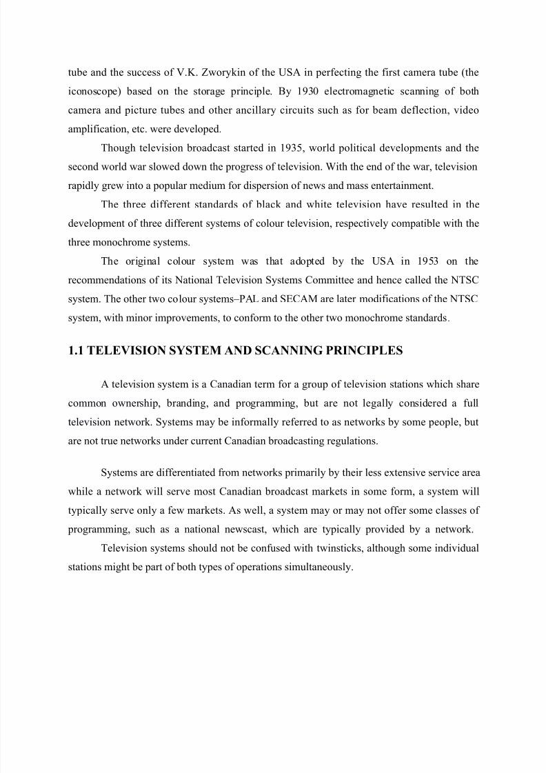
Fi$9 1.' Sc#nnin$ %roce
The scanning techniue is similar to reading and 'riting in#ormation on a page
starting at top le#t and processing to end at right ottom. The scanning is done line line.
T'o tpes o# scanning occur simultaneousl.
Horizontal scanning #rom le#t to right at #ast rate and 0erticall #rom top to ottom at
lo' rate. The retrace and trace period otained during scanning o# lines. The retrace o# eam
is 0er #ast compared to #or'ard scan cutting o## the eam during horizontal and 0ertical
#l ac% inter0als.
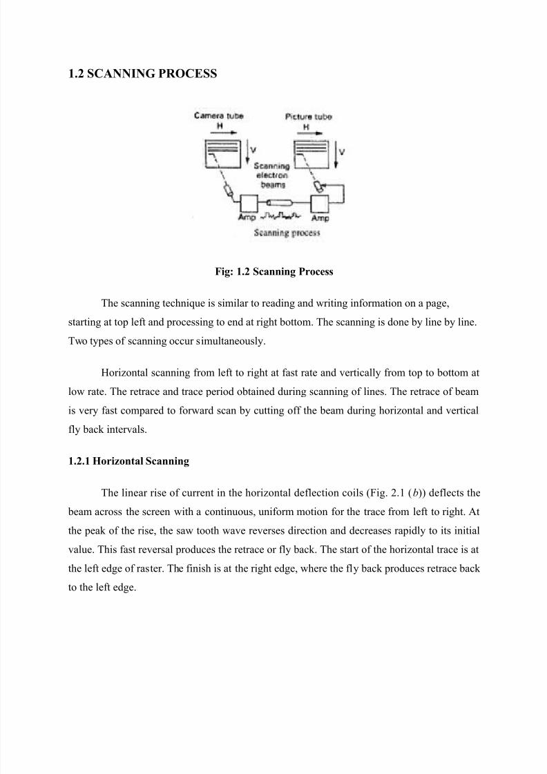
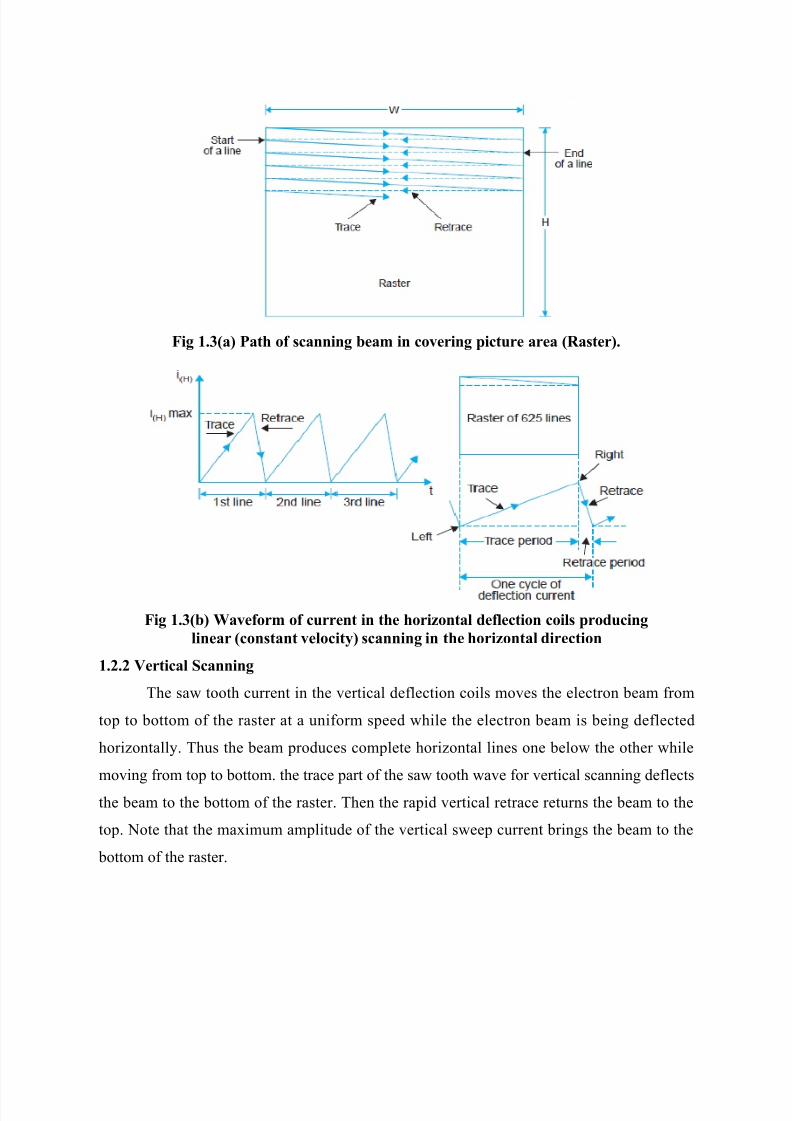
1.'.1 ,ori:ont#l Sc#nnin$
The linear rise o# current in the horizontal de#lection coils :$ig. 2.1 :b;; de#lects the
eam across the screen 'ith a continuous uni#orm motion #or the trace #rom le#t to right. At
the pea% o# the rise the sa' tooth 'a0e re0erses direction and decreases rapidl to its initial
0alue. This #ast re0ersal produces the retrace or #l ac%. The start o# the horizontal trace is at
the le#t edge o# raster. The #inish is at the right edge 'here the #l ac% produces retrace ac%
to the le#t edge.
7/26/2019 Television and video engineering
http://slidepdf.com/reader/full/television-and-video-engineering 9/42
Fi$ 1.(<#= %#t* o+ c#nnin$ 7e#" in coverin$ &icture #re# <R#ter=.
Fi$ 1.(<7= >#ve+or" o+ current in t*e *ori:ont#l de+lection coil &roducin$
line#r <cont#nt velocit!= c#nnin$ in t*e *ori:ont#l direction
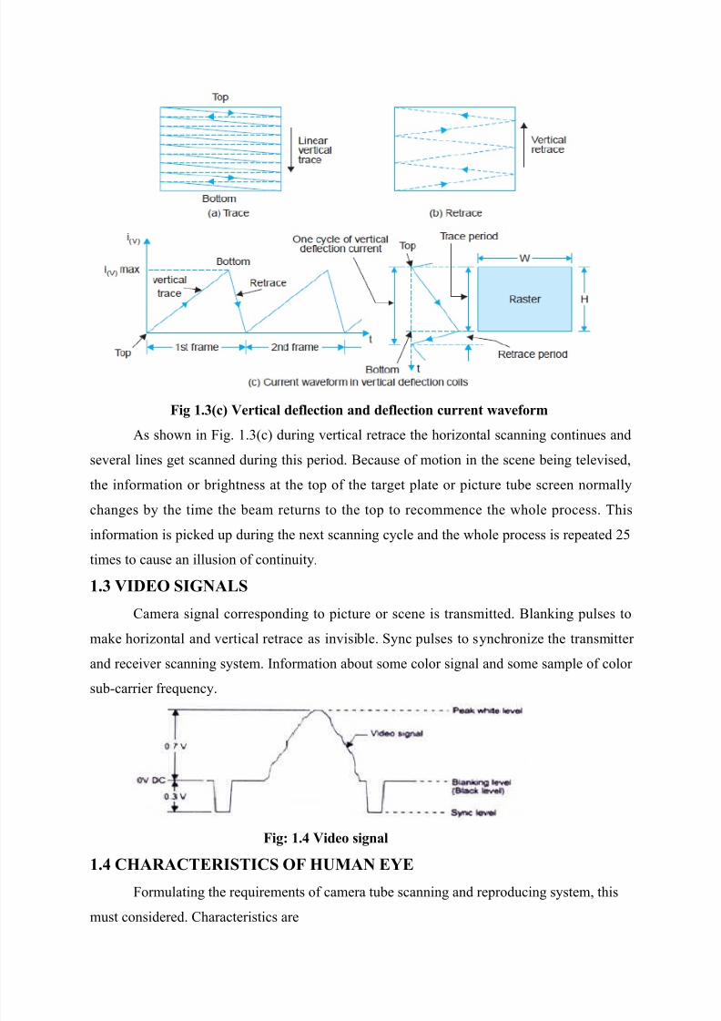
1.'.' Vertic#l Sc#nnin$
The sa' tooth current in the 0ertical de#lection coils mo0es the electron eam #rom
top to ottom o# the raster at a uni#orm speed 'hile the electron eam is eing de#lected
horizontall. Thus the eam produces complete horizontal lines one elo' the other 'hile
mo0ing #rom top to ottom. the trace part o# the sa' tooth 'a0e #or 0ertical scanning de#lects
the eam to the ottom o# the raster. Then the rapid 0ertical retrace returns the eam to the
top. Dote that the maimum amplitude o# the 0ertical s'eep current rings the eam to the
ottom o# the raster.
7/26/2019 Television and video engineering
http://slidepdf.com/reader/full/television-and-video-engineering 10/42
Fi$ 1.(<c= Vertic#l de+lection #nd de+lection current 6#ve+or"
As sho'n in $ig. 1.):c; during 0ertical retrace the horizontal scanning continues and
se0eral lines get scanned during this period. Because o# motion in the scene eing tele0ised
the in#ormation or rightness at the top o# the target plate or picture tue screen normall
changes the time the eam returns to the top to recommence the 'hole process. This
in#ormation is pic%ed up during the net scanning ccle and the 'hole process is repeated 25
times to cause an illusion o# continuit.
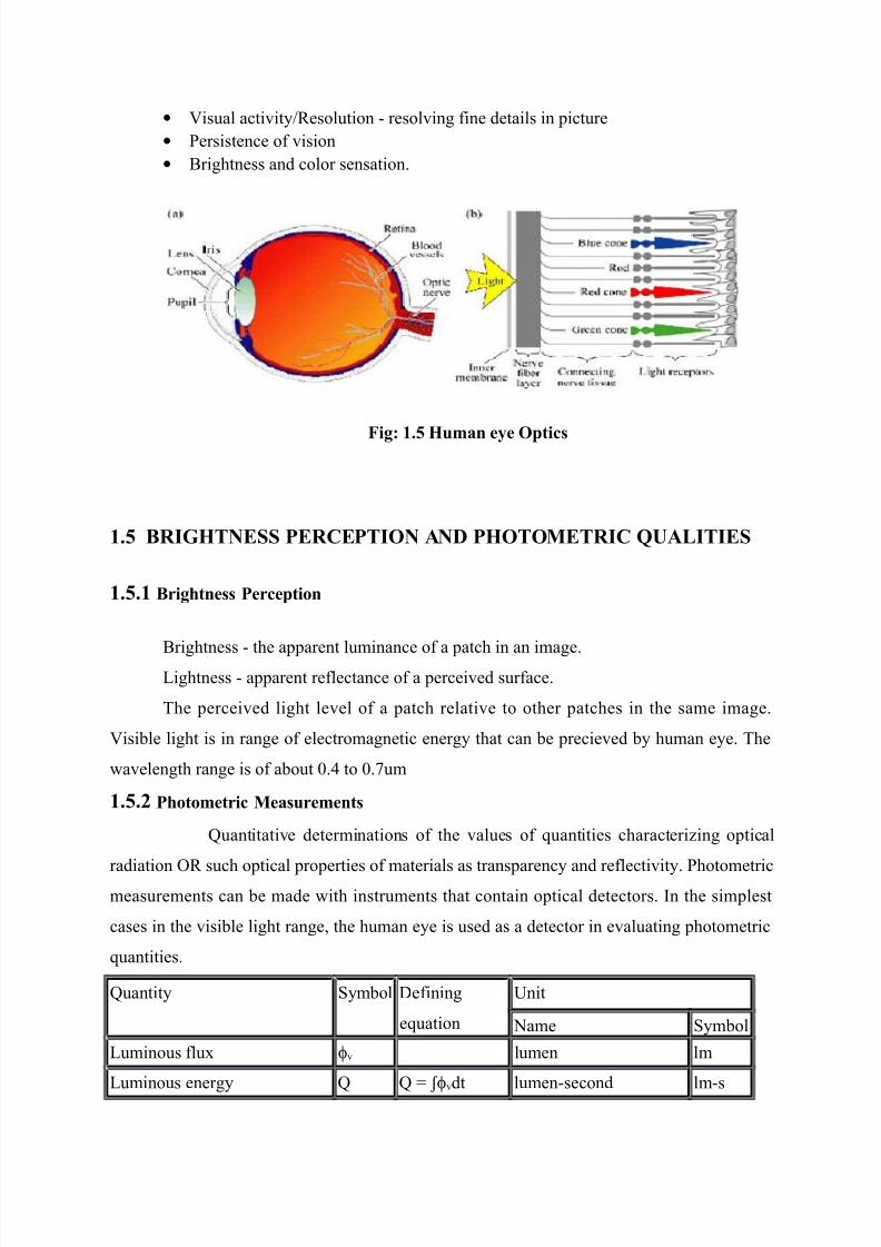
1.( VIDEO SIGNALS
,amera signal corresponding to picture or scene is transmitted. Blan%ing pulses to
ma%e horizontal and 0ertical retrace as in0isile. Snc pulses to snchronize the transmitter
and recei0er scanning sstem. (n#ormation aout some color signal and some sample o# color
suEcarrier #reuenc.
Fi$9 1.) Video i$n#l
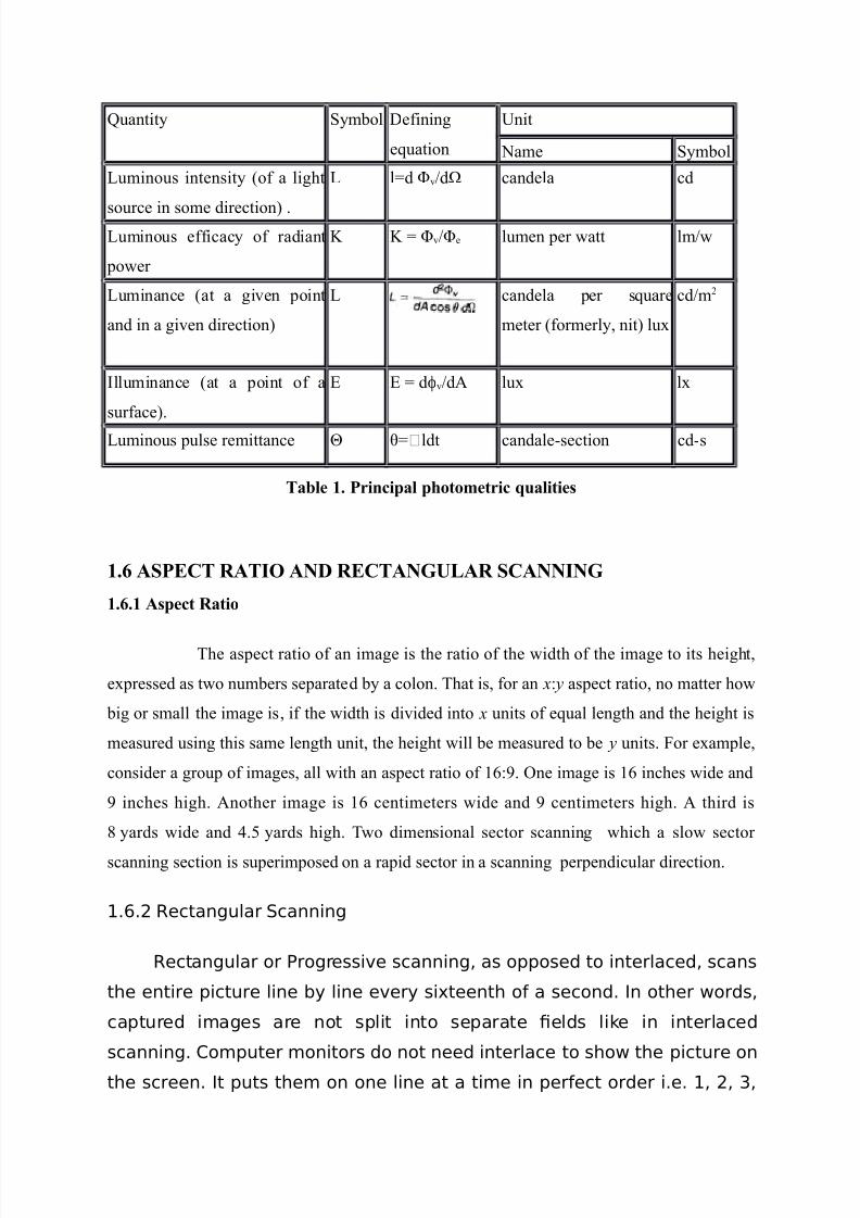
1.) C,ARACTERISTICS OF ,UMAN E;E
$ormulating the reuirements o# camera tue scanning and reproducing sstem this
must considered. ,haracteristics are
7/26/2019 Television and video engineering
http://slidepdf.com/reader/full/television-and-video-engineering 11/42
• Visual acti0itesolution E resol0ing #ine details in picture
• Persistence o# 0ision
• Brightness and color sensation.
Fi$9 1. ,u"#n e!e O&tic
1. RIG,TNESS %ERCE%TION AND %,OTOMETRIC /UALITIES
1..1 ri$*tne %erce&tion
Brightness E the apparent luminance o# a patch in an image.-ightness E apparent re#lectance o# a percei0ed sur#ace.
The percei0ed light le0el o# a patch relati0e to other patches in the same image.
Visile light is in range o# electromagnetic energ that can e precie0ed human ee. The
'a0elength range is o# aout /.& to /.!um
1..' %*oto"etric Me#ure"ent
Fuantitati0e determinations o# the 0alues o# uantities characterizing optical
radiation " such optical properties o# materials as transparenc and re#lecti0it. Photometricmeasurements can e made 'ith instruments that contain optical detectors. (n the simplest
cases in the 0isile light range the human ee is used as a detector in e0aluating photometric
uantities.
Fuantit Smol 9e#ining
euation
?nit
Dame Smol
-uminous #lu ϕ0 lumen lm
-uminous energ F F G ʃϕ0dt lumenEsecond lmEs
7/26/2019 Television and video engineering
http://slidepdf.com/reader/full/television-and-video-engineering 12/42
Fuantit Smol 9e#ining
euation
?nit
Dame Smol
-uminous intensit :o# a light
source in some direction; .
- lGd 0dI candela cd
-uminous e##icac o# radiant
po'er
@ @ G 0e lumen per 'att lm'
-uminance :at a gi0en point
and in a gi0en direction;
- candela per suare
meter :#ormerl nit; lu
cdm2
(lluminance :at a point o# a
sur#ace;.
* * G dϕ0dA lu l
-uminous pulse remittance J KGLldt candaleEsection cdEs
T#7le 1. %rinci&#l &*oto"etric ?u#litie
1.0 AS%ECT RATIO AND RECTANGULAR SCANNING
1.0.1 A&ect R#tio
The aspect ratio o# an image is the ratio o# the 'idth o# the image to its height
epressed as t'o numers separated a colon. That is #or an x3 y aspect ratio no matter ho'
ig or small the image is i# the 'idth is di0ided into x units o# eual length and the height is
measured using this same length unit the height 'ill e measured to e y units. $or eample
consider a group o# images all 'ith an aspect ratio o# 163. "ne image is 16 inches 'ide and
inches high. Another image is 16 centimeters 'ide and centimeters high. A third is
+ ards 'ide and &.5 ards high. T'o dimensional sector scanning 'hich a slo' sector
scanning section is superimposed on a rapid sector in a scanning perpendicular direction.
1.6.2 Rectangular Scanning
Rectangular or Progressive scanning, as opposed to interlaced, scans
the entire picture line ! line ever! si"teenth o# a second. In other $ords,
captured i%ages are not split into separate &elds li'e in interlaced
scanning. (o%puter %onitors do not need interlace to sho$ the picture on
the screen. It puts the% on one line at a ti%e in per#ect order i.e. 1, 2, ),
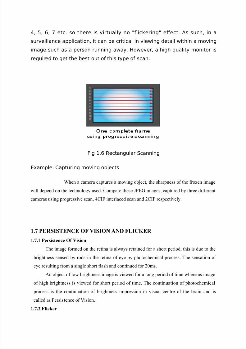
7/26/2019 Television and video engineering
http://slidepdf.com/reader/full/television-and-video-engineering 13/42
*, +, 6, etc. so there is virtuall! no -ic'ering- e/ect. s such, in a
surveillance application, it can e critical in vie$ing detail $ithin a %oving
i%age such as a person running a$a!. Ho$ever, a high ualit! %onitor is
reuired to get the est out o# this t!pe o# scan.
ig 1.6 Rectangular Scanning
3"a%ple4 (apturing %oving o5ects
4hen a camera captures a mo0ing oect the sharpness o# the #rozen image'ill depend on the technolog used. ,ompare these >P*N images captured three di##erent
cameras using progressi0e scan &,($ interlaced scan and 2,($ respecti0el.
1. %ERSISTENCE OF VISION AND FLIC5ER
1..1 %eritence O+ Viion
The image #ormed on the retina is al'as retained #or a short period this is due to the
rightness sensed rods in the retina o# ee photochemical process. The sensation o#
ee resulting #rom a single short #lash and continued #or 2/ms.
An oect o# lo' rightness image is 0ie'ed #or a long period o# time 'here as image
o# high rightness is 0ie'ed #or short period o# time. The continuation o# photochemical
process is the continuation o# rightness impression in 0isual centre o# the rain and is
called as Persistence o# Vision.
1..' Flic2er
7/26/2019 Television and video engineering
http://slidepdf.com/reader/full/television-and-video-engineering 14/42
Although the rate o# 2& pictures per second in motion pictures and that o# scanning 25
#rames per second in tele0ision pictures is enough to cause an illusion o# continuit the are
not rapid enough to allo' the rightness o# one picture or #rame to lend smoothl into the
net through the time 'hen the screen is lan%ed et'een successi0e #rames. This results in a
de#inite #lic%er o# light that is 0er annoing to the oser0er 'hen the screen is made
alternatel right and dar%. This prolem is sol0ed in motion pictures sho'ing each
picture t'ice so that &+ 0ie's o# the scene are sho'n per second although there are still the
same 2& picture #rames per second. As a result o# the increased lan%ing rate #lic%er is
eliminated.
1.3 VERTICAL RESOLUTIONThe O0ertical resolutionO o# DTS, TV re#ers to the total numer o# lines :ro's;
scanned #rom le#t to right across the screen E B?T ,ounted #rom Top to Bottom or Verticall.
This numer is set the DTS, TV Standard .This Vertic#l Reolution numer is static E it
doen@t c*#n$e. There#ore the Vertic#l Reolution i t*e #"e +or ALL TV@
"#nu+#ctured to "eet # &eci+ied St#nd#rd.
$or com#ortale 0ie'ing an angle o# aout 1/ to 15 ° can e ta%en as the optimum
0isual angle. Hence the est 0ie'ing distance #or 'atching tele0ision is aout & to + times theheight o# the picture. The maimum no. o# 'hit and dar% lines 'hich can e resol0ed
human ee in 0ertical direction o# screen o# height <H= is gi0en n0 the numer o# 0ertical
resolution .
n0GH9αo
'here
H is the height o# the screen
9 is the iris opening distance #rom centre o# image to lens
αo is the minimum angle o# resolution
Thus #or 9HG6 Visual angle is aout 1/°n0G6// lines: sututing ao0e #ormula;
1.4 5ELL FACTOR
The @ell #actor named a#ter ,A engineer amond 9. @ell is a parameter used to
limit the and'idth o# a sampled image signal to a0oid the appearance o# eat #reuenc

7/26/2019 Television and video engineering
http://slidepdf.com/reader/full/television-and-video-engineering 15/42
patterns 'hen displaing the image in discrete displa de0ices usuall ta%en to e /.!. The
numer 'as #irst measured in 1)& amond 9. @ell and his associates as /.6& ut has
su##ered se0eral re0isions gi0en that it is ased on image perception hence suecti0e and is
not independent o# the tpe o# displa. (t 'as later re0ised to /.+5 ut can go higher than /.
'hen #ied piel scanning :e.g. ,,9 or ,M"S; and #ied piel displas :e.g. -,9 or
plasma; are used or as lo' as /.! #or electron gun scanning.
$rom a di##erent perspecti0e the @ell #actor de#ines the e##ecti0e resolution o# a
discrete displa de0ice since the #ull resolution cannot e used 'ithout 0ie'ing eperience
degradation. The actual sampled resolution 'ill depend on the spot size and intensit
distriution. $or electron gun scanning sstems the spot usuall has a Naussian intensit
distriution. $or ,,9s the distriution is some'hat rectangular and is also a##ected the
sampling grid and interEpiel spacing.
@ell #actor is sometimes incorrectl stated to eist to account #or the e##ects o#
interlacing. (nterlacing itsel# does not a##ect @ell #actor ut ecause interlaced 0ideo must e
lo'Epass #iltered :i.e. lurred; in the 0ertical dimension to a0oid spatioEtemporal aliasing
:i.e. #lic%ering e##ects; the @ell #actor o# interlaced 0ideo is said to e aout !/Q that o#
progressi0e 0ideo 'ith the same scan line resolution.
1.10 HORIO79 R3SO9:IO7
The horizontal resolution o# tele0ision and other 0ideo displas is dependent upon the
ualit o# the 0ideo signals source. As an eample E the horizontal resolution o# VHS tape is
:aout; 2&/ linesR roadcast TV :aout; ))/ lines laserdisc :aout; &2/ linesR and 9V9
:aout; &+/ lines.
To a0oid getting entangled too deepl 'ithin the inherent compleities o# TVtechnolog its su##icient to note that there are a numer o# 0ariales contriuting to the
stated horizontal resolution 0alue. *0en the measurement methods are not al'as consistent.
$or instance E ho' the 0ertical columns :dotsdashes; are counted ... as single lac% 'hite
:dar% and light; lines or as Oline pairs E :1; lac% and :1; 'hite line.O
A TVs resolution can e reported as the result o# counting the total numer o# picture
elements :piels; per scan line across the entire screenE'idth multiplied the total numer
o# scan lines. Ho'e0er TV screenEsizes 0ar ma%ing an eual comparison o# di##erent
7/26/2019 Television and video engineering
http://slidepdf.com/reader/full/television-and-video-engineering 16/42
displas more comple. TVs also di##er technicall #unctionall and in component ualitR
this results in additional complications.
An alternati0e method is to count the numer o# piels that #it 'ithin a prescried
circle ha0ing a diameter eual to the screen height. @no'n as -PH E -ines per Picture
Height E this is the correct method in determining TV resolution.
As this sho's along 'ith other similar 0ariales the accurac o# a stated horizontal
resolution #or a particular displa ma depend on 'ho is doing the stating . Ho'e0er #or the
purpose o# this o0er0ie' o# H9TVEesolution the primar point regarding *ori:ont#l
reolution is that it is 0ariale. ?nli%e 0ertical resolution 'hich is @+iedB@ *ori:ont#l
reolution c#n di++er #rom one TV displa to another. (t 'ould e realistic to aim at eual0ertical and horizontal resolution and as such the numer o# alternate lac% and 'hite ars
that should e considered is eual to
Na aspect ratio G 5+5 &) G !+/
1.11 VIDEO AND>IDT,
B4S G 12 :@ A :V-T;U $; :@H @V;
4here3
B4S G Total signal and'idth
@ G @ell #actor
A G Aspect ratio :the 'idth o# the displa di0ided the height o# the displa;
V-T G Total numer o# 0ertical scan lines
$ G $rame rate or re#resh rate
@H G atio o# total horizontal piels to acti0e piels
@V G atio o# total 0ertical lines to acti0e lines
The circuits that process 0ideo signals need to ha0e more and'idth than the actual
and'idth o# the processed signal to minimize the degradation o# the signal and the resulting
loss in picture ualit. The amount the circuit and'idth needs to eceed the highest
#reuenc in the signal is a #unction o# the ualit desired. To calculate this 'e assume asingleEpole response and use the #ollo'ing euation3
7/26/2019 Television and video engineering
http://slidepdf.com/reader/full/television-and-video-engineering 17/42
H:#;:dB; G 2/log:1:1W:B4SB4E)dB;U;.5;
earranging and sol0ing #or the E/.1dB and the E/.5dB attenuation points 'e get the
#ollo'ing3
B4E)dB min G B4S :E/.1d; 6.55
B4E)dBEmin G B4S:E/.5d; 2.+6
4here3
B4E)dB G the minimum E)d and'idth reuired #or the circuit
A minimum and'idth thats aout si and a hal# times the highest #reuenc in the
signal. (# ou can tolerate /.5dB attenuation it needs to e onl aout three times. To account
#or normal 0ariations in the and'idth o# integrated circuits it is recommended that the
results #rom euations ) and & e multiplied a #actor o# 1.5. This 'ill ensure that the
attenuation per#ormance is met o0er 'orstEcase conditions. (n euation mode it is epressed
as #ollo's3
B4E)dB nominal G B4E)dBEmin 1.5
(n addition to and'idth the circuits must sle' #ast enough to #aith#ull reproduce
the 0ideo signal. The euation #or the minimum sle' rate is as #ollo's3
SM(D G 2 pi B4S Vpea%
Sustituting and simpli#ing
SM(D G B4S 6.)+6
This is ecause some distortion can occur as the #reuenc o# the signal approaches
the sle'Erate limit. This can introduce #reuenc distortion 'hich 'ill degrade the picture
ualit. (n euation #orm3
Snominal G SM(D 2
'e calculate a maimum signal and'idth :B4S; o# aout &.2MHz. This is
the highest #reuenc in the signal. Do' lets assume that 'e need less than /.1dB
attenuation. 'e calculate the minimum signal and'idth necessar to e 2!.5MHz. to
account #or 0ariations gi0es &1.)MHz.
1.12 I73R9(3; S(77I7<
(nterlaced scanEased images use techniues de0eloped #or ,athode a Tue
:,T;Eased TV monitor displas made up o# 5!6 0isile horizontal lines across a standard
7/26/2019 Television and video engineering
http://slidepdf.com/reader/full/television-and-video-engineering 18/42
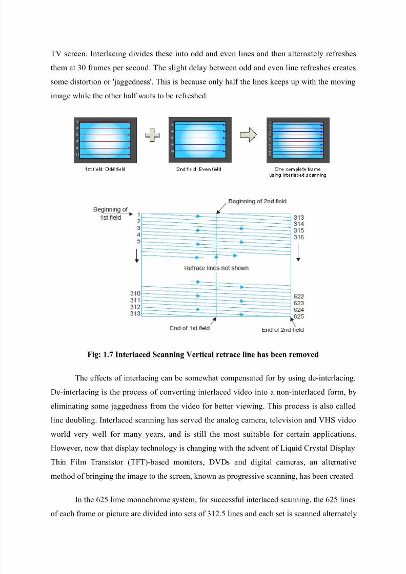
TV screen. (nterlacing di0ides these into odd and e0en lines and then alternatel re#reshes
them at )/ #rames per second. The slight dela et'een odd and e0en line re#reshes creates
some distortion or aggedness. This is ecause onl hal# the lines %eeps up 'ith the mo0ing
image 'hile the other hal# 'aits to e re#reshed.
Fi$9 1. Interl#ced Sc#nnin$ Vertic#l retr#ce line *# 7een re"oved
The e##ects o# interlacing can e some'hat compensated #or using deEinterlacing.
9eEinterlacing is the process o# con0erting interlaced 0ideo into a nonEinterlaced #orm
eliminating some aggedness #rom the 0ideo #or etter 0ie'ing. This process is also called
line douling. (nterlaced scanning has ser0ed the analog camera tele0ision and VHS 0ideo
'orld 0er 'ell #or man ears and is still the most suitale #or certain applications.
Ho'e0er no' that displa technolog is changing 'ith the ad0ent o# -iuid ,rstal 9ispla
Thin $ilm Transistor :T$T;Eased monitors 9V9s and digital cameras an alternati0e
method o# ringing the image to the screen %no'n as progressi0e scanning has een created.
(n the 625 lime monochrome sstem #or success#ul interlaced scanning the 625 lineso# each #rame or picture are di0ided into sets o# )12.5 lines and each set is scanned alternatel
7/26/2019 Television and video engineering
http://slidepdf.com/reader/full/television-and-video-engineering 19/42
to co0er the entire picture area. To achie0e this the horizontal s'eep oscillator is made to
'or% at a #reuenc o# 15625 Hz :)12.5 5/ G 15625; to scan the same numer o# lines per
#rame :1562525 G 625 lines; ut the 0ertical s'eep circuit is run at a #reuenc o# 5/ instead
o# 25 Hz. Dote that since the eam is no' de#lected #rom top to ottom in hal# the time and
the horizontal oscillator is still operating at 15625 Hz onl hal# the total lines i.e., )12.5
:6252 G)12.5; get scanned during each 0ertical s'eep. Since the #irst #ield ends in a hal# line
and the second #ield commences at middle o# the line on the top o# the target plate or screen
the eam is ale to scan the remaining )12.5 alternate lines during its do'n'ard ourne. (n
all then the eam scans 625 lines :)12.5 2 G 625; per #rame at the same rate o# 15625 lines
:)12.5 5/ G 15625; per second. There#ore 'ith interlaced scanning the #lic%er e##ect is
eliminated 'ithout increasing the speed o# scanning 'hich in turn does not need an increase
in the channel and'idth.
1.1( CAMERA TUES
A TV camera tue ma e called the ee o# a TV sstem. $or such an analog to e
correct the tue must possess characteristic that are similar to its human counterpart. Some o#
the more important #unctions must e :i; sensiti0it to 0isile light : ii; 'ide dnamic range
'ith respect to light intensit and :iii; ailit to resol0e details 'hile 0ie'ing a multi element
scene. 9uring the de0elopment o# tele0ision the limiting #actor on the ultimate per#ormance
had al'as een the opticalEelectrical con0ersion de0ice i.e., the pic%Eup tue.
Most tpes de0eloped ha0e su##ered to a greater or lesser etent #rom :i; poor
sensiti0it :ii; poor resolution:iii; high noise le0el :iv; undesirale spectral response :v;
instailit :vi; poor contrast range and :vii; di##iculties o# processing.
Ho'e0er de0elopment 'or% during the past #i#t ears or so has enaled scientists
and engineers to de0elop image pic%Eup tues 'hich not onl meet the desired reuirements
ut in#act ecel the human ee in certain respects. Such sensiti0e tues ha0e no' een
de0eloped 'hich deli0er output e0en 'here our ees see complete dar%ness.
7/26/2019 Television and video engineering
http://slidepdf.com/reader/full/television-and-video-engineering 20/42
1.1) CAMERA LENSES
1.1).1 Len Foc#l Len$t*
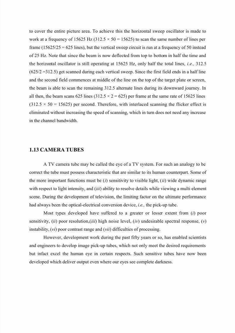
4e de#ine #ocal length as the distance #rom the optical center o# the lens to the #ocal
plane :target or OchipO; o# the 0ideo camera 'hen the lens is #ocused at in#init.
4e consider an oect in the #ar distance to e at in#init. "n a camera lens the smol
:similar to an O+O on its side; indicates in#init.
Since the lensEtoEtarget distance #or most lenses increases 'hen 'e #ocus the lens on
anthing closer than in#init :see second illustration; 'e speci# in#init as the standard #or
#ocal length measurement.
$ocal length is generall measured in millimeters. (n the case o# lenses 'ith #ied
#ocal lengths 'e can tal% aout a 1/mm lens a 2/mm lens a 1//mm lens etc. As 'e 'ill
see this designation tells a lot aout ho' the lens 'ill reproduce suect matter.
Fi$ 1.3 oo" #nd %ri"e Lene
Coom lenses came into common use in the earl 16/s. Be#ore then TV cameras used
lenses o# di##erent #ocal lengths mounted on a turret on the #ront o# the camera as sho'n on
7/26/2019 Television and video engineering
http://slidepdf.com/reader/full/television-and-video-engineering 21/42
the right. The cameraperson rotated each lens into position and #ocused it 'hen the camera
'as not on the air.
Toda most 0ideo cameras use zoom lenses. ?nli%e the #our lenses sho'n here each
o# 'hich operate at onl one #ocal length the e##ecti0e #ocal length o# a zoom lens can e
continuousl 0aried. This tpicall means that the lens can go #rom a 'ideEangle to a
telephoto perspecti0e.
To ma%e this possile zoom lenses use numerous glass elements each o# 'hich is
precisel ground polished and positioned. The space et'een these elements changes as the
lens is zoomed in and out.
>ith prime lenses the #ocal length o# the lens cannot e 0aried. (t might seem that 'e
'ould e ta%ing a step ac%'ards to use a prime lens or a lens that operates at onl one #ocal
length. Dot necessaril. Some pro#essional 0ideographers and directors o# photograph
especiall those 'ho ha0e their roots in #ilm #eel prime lenses are more predictale in their
results. Prime lenses also come in more specialized #orms #or eample super 'ide angle
super telephoto and super #ast :i.e. it transmits more light;.
Ho'e0er #or normal 'or% zoom lenses are much easier and #aster to use. The latest
o# H9TV zoom lenses are etremel sharp EE almost as sharp as the est prime lenses.
1.1).' An$le o+ Vie6
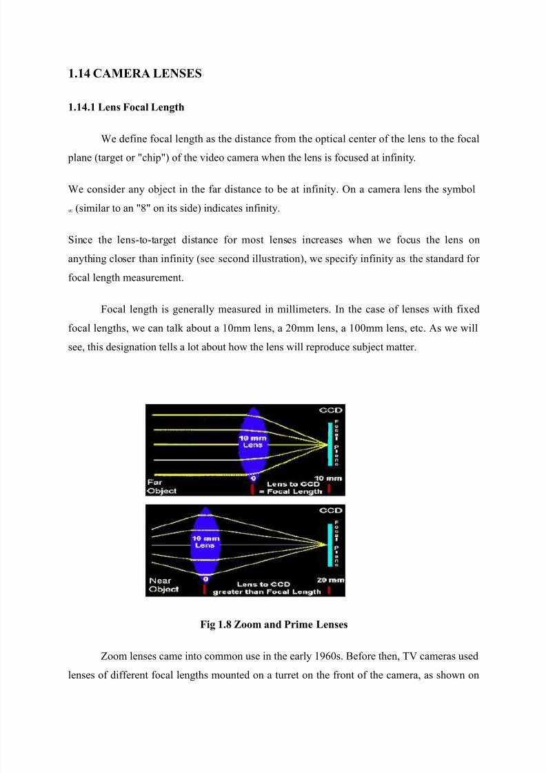
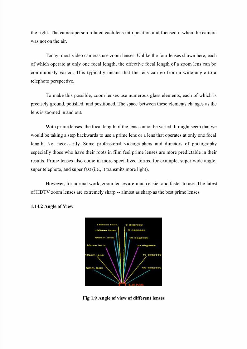
Fi$ 1.4 An$le o+ vie6 o+ di++erent lene
7/26/2019 Television and video engineering
http://slidepdf.com/reader/full/television-and-video-engineering 22/42
Angle o# 0ie' is directl associated 'ith lens #ocal length. The longer the #ocal length
:in millimeters; the narro'er the angle o# 0ie' :in degrees;. Xou can see this relationship
studing the dra'ing on the le#t 'hich sho's angles o# 0ie' #or di##erent prime lenses.
A telephoto lens :or a zoom lens operating at maimum #ocal length; has a narro'
angle o# 0ie'. Although there is no eact de#inition #or a OtelephotoO designation 'e 'ould
consider the angles at the top o# the dra'ing #rom aout ) to 1/ degrees in the telephoto
range.
The ottom o# the dra'ing :#rom aout &5 to / degrees; represents the 'ideEangle
range. The normal angle o# 0ie' range lies et'een telephoto and 'ide angle. 4ith the
camera in the same position a short #ocal lens creates a 'ide 0ie' and a long #ocal lengthcreates an enlarged image in the camera.
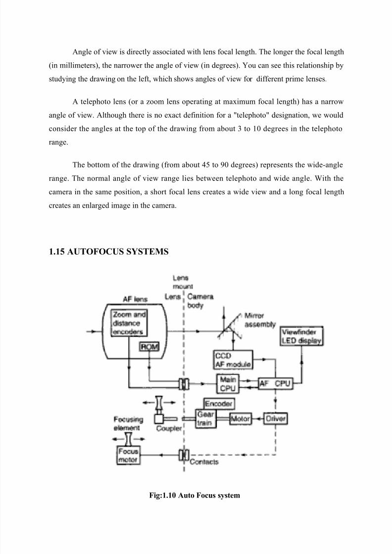
1.1 AUTOFOCUS S;STEMS
Fi$91.18 Auto Focu !te"
7/26/2019 Television and video engineering
http://slidepdf.com/reader/full/television-and-video-engineering 23/42
There are t'o main 'as #or cameras to #ocus automaticall3 contrast detection and
phase detection. The #ormer uses data #rom the ,,9 or ,M"S sensor and loo%s at ho'
sharp the resulting photograph 'ould e. (ts simple ut slo' as the camera has to go
through all o# the possiilities until it #inds one 'here the suect is clearl contrasted #rom
the ac%ground. The latter uses a tool that 'or%s li%e a range#inder 'hich accuratel
calculates the correction needed to get the suect in #ocus. (ts #ast ut di##icult to operate as
the light coming into the lens needs to reach oth the phase detector and the sensor :or the
#ilm; at the same time. This has meant that phase detection has traditionall een
reser0ed #or S-s 'hich alread ha0e a mirror that sends the image to the 0ie'#inder. At
the same time a second mirror also sends it do'n to the phase detector. 4hile #ocusing is
ta%ing place the sensor is co0ered these mirrors 'hich rules out 0ideo. S-s that do
shoot 0ideo #old their mirrors out o# the 'a and rel on the contrast detection #ound on
ordinar compacts.
1.10 CAMERA %IC5 U% DEVICES
The scene o# picture is #ocused 'ith help o# lens sstem on a photosensiti0e target
near a pic%up tue. The electrical state o# each area 0aries 'ith intensit o# light. The
electrical response o# each element is read o# # 'ith help o# electron eam circuit produce
electrical pulses. The target plate is held 'ith electrical potential 'ith respect to cathode o#
pic% up tues. The actual eam 0aries in accordance 'ith electrical state o# picture element.
The eam scans the image horizontall means o# magnetic #ield setup
horizontal de#lection coil. Similarl the eams scan the image 0erticall means o#
magnetic #ield setup 0ertical de#lection coil. The scanning must done in #ast speed o0er the
changing or mo0ing pictures.
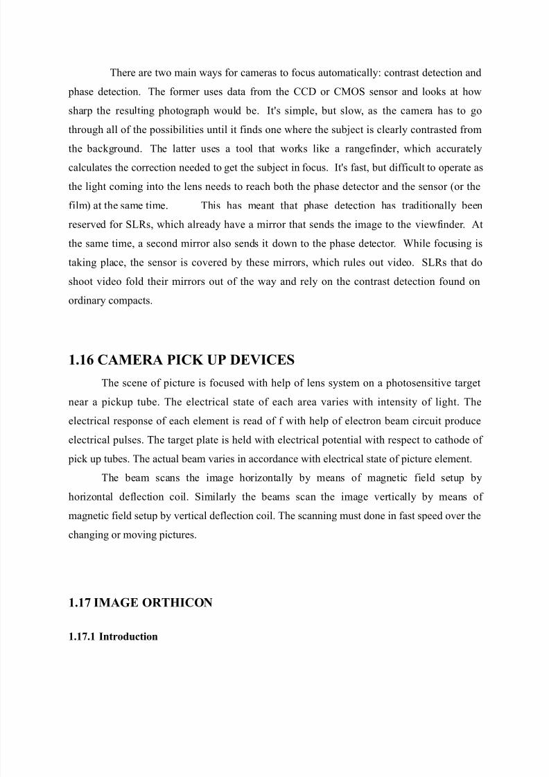
1.1 IMAGE ORT,ICON
1.1.1 Introduction
7/26/2019 Television and video engineering
http://slidepdf.com/reader/full/television-and-video-engineering 24/42
The image orthicon 'as common in American roadcasting #rom 1&6 until 16+. A
comination o# the image dissector and the orthicon technologies it replaced the iconoscope
and the orthicon 'hich reuired a great deal o# light to 'or% adeuatel.
4hile the iconoscope and the intermediate orthicon used capacitance et'een a
multitude o# small ut discrete light sensiti0e collectors and an isolated signal plate #or
reading 0ideo in#ormation the image orthicon emploed direct charge readings #rom a
continuous electronicall charged collector. The resultant signal 'as immune to most
etraneous signal Ocrosstal%O #rom other parts o# the target and could ield etremel
detailed images. $or instance image orthicon cameras 'ere used #or capturing ApolloSaturn
roc%ets nearing orit a#ter the net'or%s had phased them out as onl the could pro0ide
su##icient detail.
An image orthicon camera can ta%e tele0ision pictures candlelight ecause o# the
more ordered lightEsensiti0e area and the presence o# an electron multiplier at the ase o# the
tue 'hich operated as a highEe##icienc ampli#ier. (t also has a logarithmic light sensiti0it
cur0e similar to the human ee. Ho'e0er it tends to #lare in right light causing a dar% halo
to e seen around the oectR this anomal is re#erred to as OloomingO in the roadcast
industr 'hen image orthicon tues 'ere in operation. (mage orthicons 'ere used
etensi0el in the earl color tele0ision cameras 'here their increased sensiti0it 'as
essential to o0ercome their 0er ine##icient optical sstem.
Fi$91.11 I"#$e ort*icon
1.1.' O&er#tion
7/26/2019 Television and video engineering
http://slidepdf.com/reader/full/television-and-video-engineering 25/42
An image orthicon consists o# three parts3 a photocathode 'ith an image store
:OtargetO; a scanner that reads this image :an electron gun; and a multistage electron
multiplier.
(n the image store light #alls upon the photocathode 'hich is a photosensiti0e plate at a 0er
negati0e potential :appro. E6// V; and is con0erted into an electron image :a principle
orro'ed #rom the image dissector;. "nce the image electrons reach the target the cause a
OsplashO o# electrons the e##ect o# secondar emission. "n a0erage each image electron
eects se0eral OsplashO and these ecess electrons are soa%ed up the positi0e mesh
e##ecti0el remo0ing electrons #rom the target and causing a positi0e charge on it in relation
to the incident light in the photocathode. The result is an image painted in positi0e charge
'ith the rightest portions ha0ing the largest positi0e charge.
A sharpl #ocused eam o# electrons :a cathode ra; is generated the electron gun
at ground potential and accelerated the anode around the gun at a high positi0e 0oltage
:appro. W15// V;. "nce it eits the electron gun its inertia ma%es the eam mo0e a'a
#rom the dnode to'ards the ac% side o# the target.
At this point the electrons lose speed and get de#lected the horizontal and 0ertical
de#lection coils e##ecti0el scanning the target. Than%s to the aial magnetic #ield o# the
#ocusing coil this de#lection is not in a straight line thus 'hen the electrons reach the target
the do so perpendicularl a0oiding a side'as component.
1.1.( I"#$e Section
The inside o# the glass #ace plate at the #ront is coated 'ith a sil0er antimon coating
sensitized 'ith cesium to ser0e as photocathode. -ight #rom the scene to e tele0ised is
#ocused on the photocathode sur#ace a lens sstem and the optical image thus #ormed
results in the release o# electrons #rom each point on the photocathode in proportion to the
incident light intensit. Photocathode sur#ace is semitransparent and the light ras penetrate it
7/26/2019 Television and video engineering
http://slidepdf.com/reader/full/television-and-video-engineering 26/42
to reach its inner sur#ace #rom 'here electron emission ta%es place. Since the numer o#
electrons emitted at an point in the photocathode has a distriution corresponding to the
rightness o# the optical image an electron image o# the scene or picture gets #ormed on the
target side o# the photo coating and etends to'ards it. Through the con0ersion e##icienc o#
the photocathode is uite high it cannot store charge eing a conductor. $or this reason the
electron image produced at the photocathode is made to mo0e to'ards the target plate located
at a short distance #rom it. The target plate is made o# a 0er thin sheet o# glass and can store
the charge recei0ed it. This is maintained at aout &// 0olts more positi0e 'ith respect to
the photocathode and the resultant electric #ield gi0es the desired acceleration and motion to
the emitted electrons to'ards it. The 'ireEmesh screen has aout )// meshes per cm2 'ith an
open area o# 5/ to !5 per cent so that the screen 'ires do not inter#ere 'ith the electron
image. the target plate is 0er thin 'ith thic%ness close to /.//& mm.
1.1.) Sc#nnin$ Section
The electron gun structure produces a eam o# electrons that is accelerated to'ards
the target. As indicated in the #igure positi0e accelerating potentials o# +/ to ))/ 0olts are
applied to grid 2 grid ) and grid & 'hich is connected internall to the metalized conducti0e
coating on the inside 'all o# the tue. The electron eam is #ocused at the target magnetic
#ield o# the eternal #ocus coil and 0oltage supplied to grid &. The alignment coil pro0ides
magnetic #ield that can e 0aried to adust the scanning eam=s position i# necessar #or
correct location. 9e#lection o# electron eam=s to scan the entire target plate is accomplished
magnetic #ields o# 0ertical and horizontal de#lecting coils mounted on o%e eternal to the
tue. These coils are #ed #rom t'o oscillators one 'or%ing at 15625 Hz #or horizontal
de#lection and the other operating at 5/ Hz #or 0ertical de#lection. operating at 5/ Hz #or
0ertical de#lection. The target plate is close to zero potential and there#ore electrons in the
scanning eam can e made to stop their #or'ard motion at its sur#ace and then return
to'ards the gun structure.
1.1. Electron Multi&lier
The returning stream o# electrons arri0e at the gun close to the aperture #rom 'hich
electron eam emerged. The aperture is a part o# a metal disc co0ering the gun electrode.
4hen the returning electrons stri%e the disc 'hich is at a positi0e potential o# aout )//
0olts 'ith respect to the target the produce secondar emission. The disc ser0es as #irst
7/26/2019 Television and video engineering
http://slidepdf.com/reader/full/television-and-video-engineering 27/42
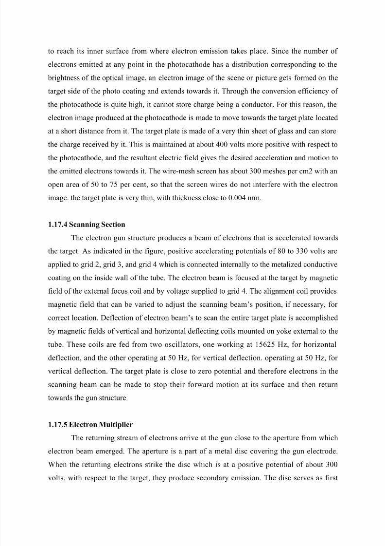
stage o# the electron multiplier. Successi0e stages o# the electron multiplier are arranged
smmetricall around and ac% o# the #irst stage.
Fi$ 1.1' Electron-"ulti&lier ection o+ t*e I"#$e Ort*icon.
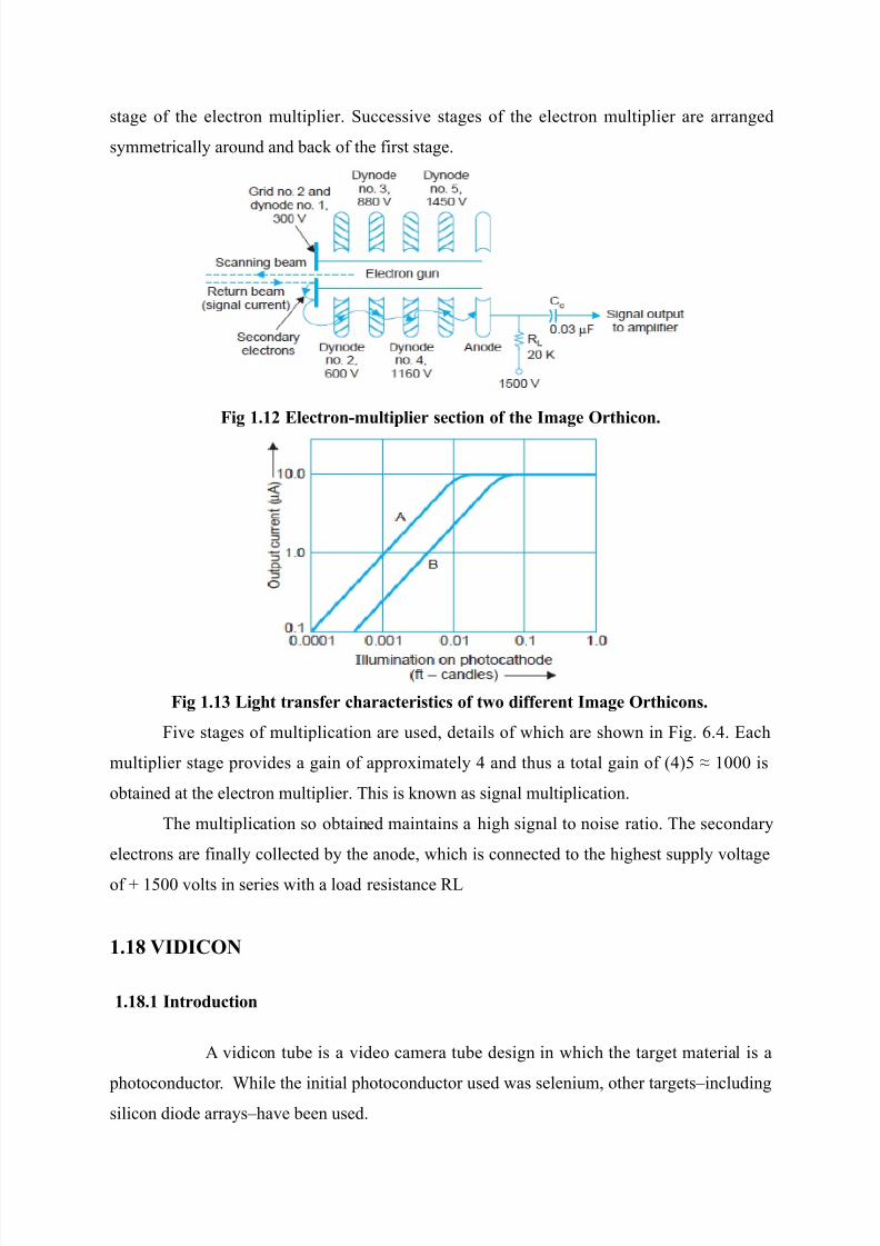
Fi$ 1.1( Li$*t tr#n+er c*#r#cteritic o+ t6o di++erent I"#$e Ort*icon.
$i0e stages o# multiplication are used details o# 'hich are sho'n in $ig. 6.&. *ach
multiplier stage pro0ides a gain o# approimatel & and thus a total gain o# :&;5 Y 1/// is
otained at the electron multiplier. This is %no'n as signal multiplication.
The multiplication so otained maintains a high signal to noise ratio. The secondar
electrons are #inall collected the anode 'hich is connected to the highest suppl 0oltage
o# W 15// 0olts in series 'ith a load resistance -
1.13 VIDICON
1.13.1 Introduction
A 0idicon tue is a 0ideo camera tue design in 'hich the target material is a
photoconductor. 4hile the initial photoconductor used 'as selenium other targets7includingsilicon diode arras7ha0e een used.
7/26/2019 Television and video engineering
http://slidepdf.com/reader/full/television-and-video-engineering 28/42
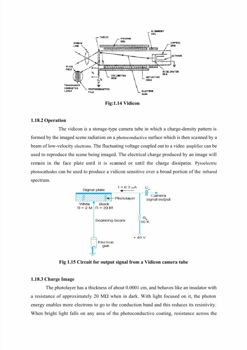
Fi$91.1) Vidicon
1.13.' O&er#tion The 0idicon is a storageEtpe camera tue in 'hich a chargeEdensit pattern is
#ormed the imaged scene radiation on a photoconducti0e sur#ace 'hich is then scanned a
eam o# lo'E0elocit electrons. The #luctuating 0oltage coupled out to a 0ideo ampli#ier can e
used to reproduce the scene eing imaged. The electrical charge produced an image 'ill
remain in the #ace plate until it is scanned or until the charge dissipates. Proelectric
photocathodes can e used to produce a 0idicon sensiti0e o0er a road portion o# the in#rared
spectrum.
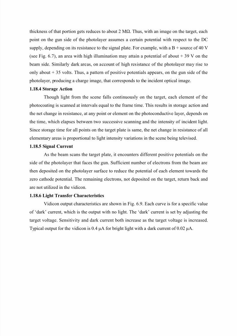
Fi$ 1.1 Circuit +or out&ut i$n#l +ro" # Vidicon c#"er# tu7e
1.13.( C*#r$e I"#$e
The photolaer has a thic%ness o# aout /.///1 cm and eha0es li%e an insulator 'ith
a resistance o# approimatel 2/ MI 'hen in dar%. 4ith light #ocused on it the photon
energ enales more electrons to go to the conduction and and this reduces its resisti0it.4hen right light #alls on an area o# the photoconducti0e coating resistance across the
7/26/2019 Television and video engineering
http://slidepdf.com/reader/full/television-and-video-engineering 29/42
thic%ness o# that portion gets reduces to aout 2 MI. Thus 'ith an image on the target each
point on the gun side o# the photolaer assumes a certain potential 'ith respect to the 9,
suppl depending on its resistance to the signal plate. $or eample 'ith a B W source o# &/ V
:see $ig. 6.!; an area 'ith high illumination ma attain a potential o# aout W ) V on the
eam side. Similarl dar% areas on account o# high resistance o# the photolaer ma rise to
onl aout W )5 0olts. Thus a pattern o# positi0e potentials appears on the gun side o# the
photolaer producing a charge image that corresponds to the incident optical image.
1.13.) Stor#$e Action
Though light #rom the scene #alls continuousl on the target each element o# the
photocoating is scanned at inter0als eual to the #rame time. This results in storage action and
the net change in resistance at an point or element on the photoconducti0e laer depends on
the time 'hich elapses et'een t'o successi0e scanning and the intensit o# incident light.
Since storage time #or all points on the target plate is same the net change in resistance o# all
elementar areas is proportional to light intensit 0ariations in the scene eing tele0ised.
1.13. Si$n#l Current
As the eam scans the target plate it encounters di##erent positi0e potentials on the
side o# the photolaer that #aces the gun. Su##icient numer o# electrons #rom the eam are
then deposited on the photolaer sur#ace to reduce the potential o# each element to'ards the
zero cathode potential. The remaining electrons not deposited on the target return ac% and
are not utilized in the 0idicon.
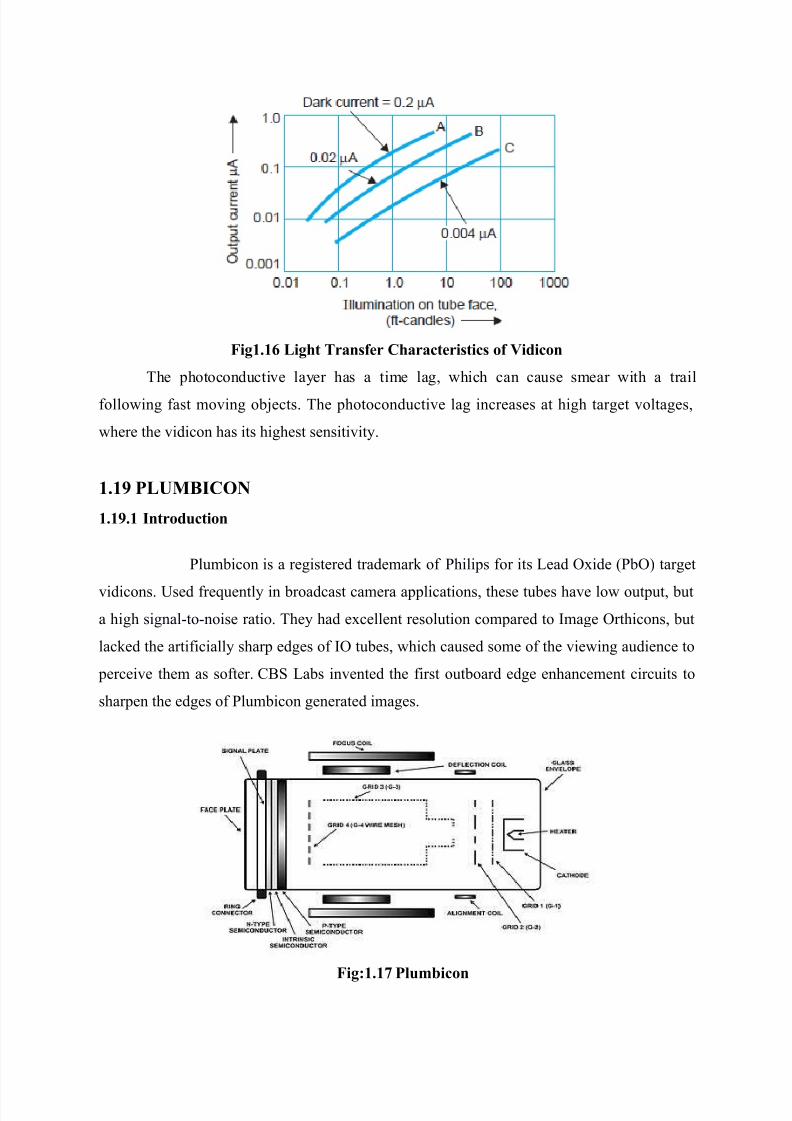
1.13.0 Li$*t Tr#n+er C*#r#cteritic
Vidicon output characteristics are sho'n in $ig. 6.. *ach cur0e is #or a speci#ic 0alue
o# <dar%= current 'hich is the output 'ith no light. The <dar%= current is set adusting the
target 0oltage. Sensiti0it and dar% current oth increase as the target 0oltage is increased.
Tpical output #or the 0idicon is /.& ZA #or right light 'ith a dar% current o# /./2 ZA.
7/26/2019 Television and video engineering
http://slidepdf.com/reader/full/television-and-video-engineering 30/42
Fi$1.10 Li$*t Tr#n+er C*#r#cteritic o+ Vidicon
The photoconducti0e laer has a time lag 'hich can cause smear 'ith a trail
#ollo'ing #ast mo0ing oects. The photoconducti0e lag increases at high target 0oltages
'here the 0idicon has its highest sensiti0it.
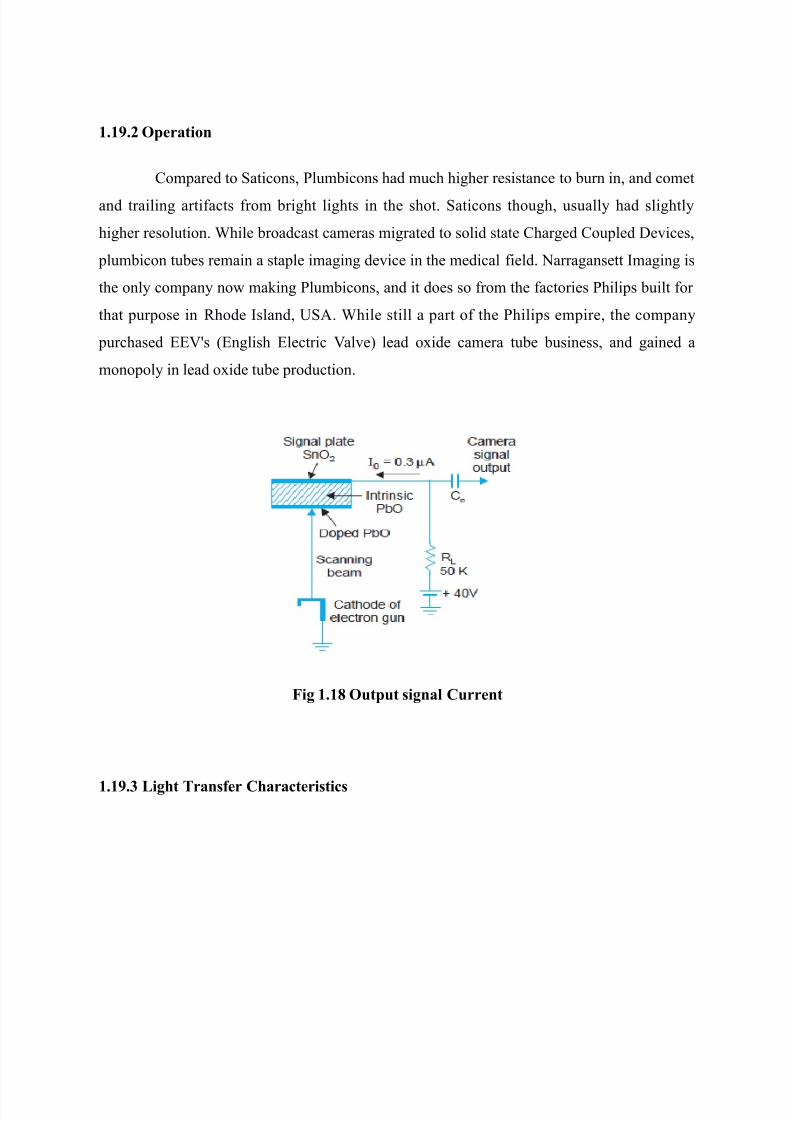
1.14 %LUMICON
1.14.1 Introduction
Plumicon is a registered trademar% o# Philips #or its -ead "ide :P"; target
0idicons. ?sed #reuentl in roadcast camera applications these tues ha0e lo' output ut
a high signalEtoEnoise ratio. The had ecellent resolution compared to (mage "rthicons ut
lac%ed the arti#iciall sharp edges o# (" tues 'hich caused some o# the 0ie'ing audience to
percei0e them as so#ter. ,BS -as in0ented the #irst outoard edge enhancement circuits to
sharpen the edges o# Plumicon generated images.
Fi$91.1 %lu"7icon
7/26/2019 Television and video engineering
http://slidepdf.com/reader/full/television-and-video-engineering 31/42
1.14.' O&er#tion
,ompared to Saticons Plumicons had much higher resistance to urn in and comet
and trailing arti#acts #rom right lights in the shot. Saticons though usuall had slightl
higher resolution. 4hile roadcast cameras migrated to solid state ,harged ,oupled 9e0ices
plumicon tues remain a staple imaging de0ice in the medical #ield. Darragansett (maging is
the onl compan no' ma%ing Plumicons and it does so #rom the #actories Philips uilt #or
that purpose in hode (sland ?SA. 4hile still a part o# the Philips empire the compan
purchased **Vs :*nglish *lectric Val0e; lead oide camera tue usiness and gained a
monopol in lead oide tue production.
Fi$ 1.13 Out&ut i$n#l Current
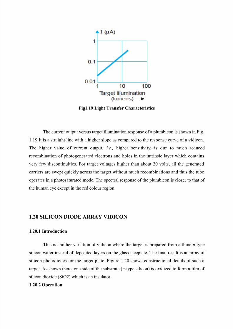
1.14.( Li$*t Tr#n+er C*#r#cteritic
7/26/2019 Television and video engineering
http://slidepdf.com/reader/full/television-and-video-engineering 32/42
Fi$1.14 Li$*t Tr#n+er C*#r#cteritic
The current output 0ersus target illumination response o# a plumicon is sho'n in $ig.
1.1 (t is a straight line 'ith a higher slope as compared to the response cur0e o# a 0idicon.
The higher 0alue o# current output i.e., higher sensiti0it is due to much reduced
recomination o# photogenerated electrons and holes in the intrinsic laer 'hich contains
0er #e' discontinuities. $or target 0oltages higher than aout 2/ 0olts all the generated
carriers are s'ept uic%l across the target 'ithout much recominations and thus the tue
operates in a photosaturated mode. The spectral response o# the plumicon is closer to that o#
the human ee ecept in the red colour region.
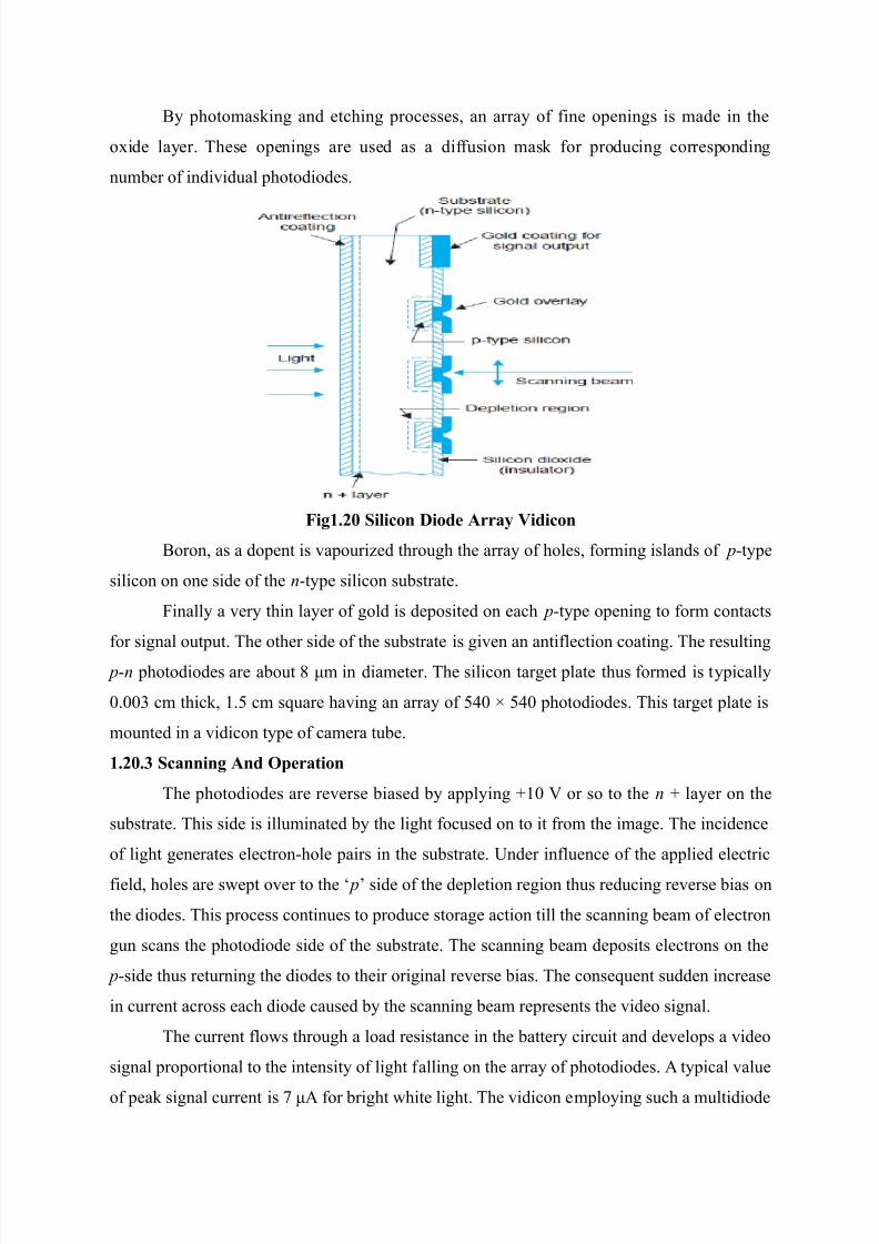
1.'8 SILICON DIODE ARRA; VIDICON
1.'8.1 Introduction
This is another 0ariation o# 0idicon 'here the target is prepared #rom a thine nEtpe
silicon 'a#er instead o# deposited laers on the glass #aceplate. The #inal result is an arra o#
silicon photodiodes #or the target plate. $igure 1.2/ sho's constructional details o# such a
target. As sho'n there one side o# the sustrate :nEtpe silicon; is oidized to #orm a #ilm o#
silicon dioide :Si"2; 'hich is an insulator.
1.'8.' O&er#tion
7/26/2019 Television and video engineering
http://slidepdf.com/reader/full/television-and-video-engineering 33/42
B photomas%ing and etching processes an arra o# #ine openings is made in the
oide laer. These openings are used as a di##usion mas% #or producing corresponding
numer o# indi0idual photodiodes.
Fi$1.'8 Silicon Diode Arr#! Vidicon
Boron as a dopent is 0apourized through the arra o# holes #orming islands o# pEtpe
silicon on one side o# the nEtpe silicon sustrate.
$inall a 0er thin laer o# gold is deposited on each pEtpe opening to #orm contacts
#or signal output. The other side o# the sustrate is gi0en an anti#lection coating. The resulting
pEn photodiodes are aout + Zm in diameter. The silicon target plate thus #ormed is tpicall
/.//) cm thic% 1.5 cm suare ha0ing an arra o# 5&/ 5&/ photodiodes. This target plate is
mounted in a 0idicon tpe o# camera tue.
1.'8.( Sc#nnin$ And O&er#tion
The photodiodes are re0erse iased appling W1/ V or so to the n W laer on the
sustrate. This side is illuminated the light #ocused on to it #rom the image. The incidence
o# light generates electronEhole pairs in the sustrate. ?nder in#luence o# the applied electric
#ield holes are s'ept o0er to the < p= side o# the depletion region thus reducing re0erse ias on
the diodes. This process continues to produce storage action till the scanning eam o# electron
gun scans the photodiode side o# the sustrate. The scanning eam deposits electrons on the
pEside thus returning the diodes to their original re0erse ias. The conseuent sudden increase
in current across each diode caused the scanning eam represents the 0ideo signal.
The current #lo's through a load resistance in the atter circuit and de0elops a 0ideo
signal proportional to the intensit o# light #alling on the arra o# photodiodes. A tpical 0alue
o# pea% signal current is ! ZA #or right 'hite light. The 0idicon emploing such a multidiode

7/26/2019 Television and video engineering
http://slidepdf.com/reader/full/television-and-video-engineering 34/42
silicon target is less susceptile to damage or urns due to ecessi0e high lights. (t also has
lo' lag time and high sensiti0it to 0isile light 'hich can e etended to the in#rared region.
A particular ma%e o# such a 0idicon has the trade name o# <*picon=. Such camera tues ha0e
'ide applications in industrial educational and cct0 :closed circuit tele0ision; ser0ices.
1.'1 CCD SOLID STATE IMAGE SCANNERS
The operation o# solid state image scanners is ased on M"S circuitr. The ,,9 ma
e thought to e in a shi#t register #ormed a string o# 0er closel spaced M"S capacitors.
(t can store and trans#er analog charge signals either electrons or holes in electricall or opticall.
Fi$91.'1 A t*ree &*#e n-c*#nnel MOS c*#r$e cou&led device. <#= contruction <7=tr#n+er o+ electron 7et6een &otenti#l 6ell <c= di++erent &*#e o+ cloc2in$ volt#$e
6#ve+or".
4hile roadcast cameras migrated to solid state ,harged ,oupled 9e0ices
plumicon tues remain a staple imaging de0ice in the medical #ield. Darragansett (maging is
the onl compan no' ma%ing Plumicons and it does so #rom the #actories Philips uilt #or
that purpose in hode (sland ?SA.
4hile still a part o# the Philips empire the compan purchased **Vs :*nglish*lectric Val0e; lead oide camera tue usiness and gained a monopol in lead oide tue
7/26/2019 Television and video engineering
http://slidepdf.com/reader/full/television-and-video-engineering 35/42
production.The application o# small positi0e potentials to the gate electrodes results in the
de0elopment o# depletion regions ust elo' them.
These are called potential 'ells. The depth o# each 'ell :depletion region; 0aries 'ith
the magnitude o# the applied potential. The gate electrodes operate in groups o# three 'ith
e0er third electrode connected to a common conductor.
The spots under them ser0e as light sensiti0e elements. 4hen an image is #ocused
onto the silicon chip electrons are generated 'ithin it ut 0er close to the sur#ace. The
numer o# electrons depends on the intensit o# incident light. "nce produced the collect in
the near potential 'ells. As a result the pattern o# collected charges represents the optical
image.
C*#r$e Tr#n+er
The charge o# one element is trans#erred along the sur#ace o# the silicon chip
appling a more positi0e 0oltage to the adacent electrode or gate 'hile reducing the 0oltage
on it.
The minorit carriers :electrons in this case; 'hile accumulating in the so called 'ells
reduce their depths much li%e the 'a a #luid #ills up in a container. The accumulation o#
charge carries under the #irst potential 'ells o# t'o consecuti0e trios
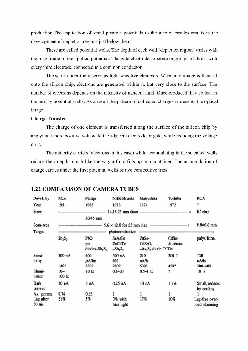
1.'' COM%ARISON OF CAMERA TUES
7/26/2019 Television and video engineering
http://slidepdf.com/reader/full/television-and-video-engineering 36/42
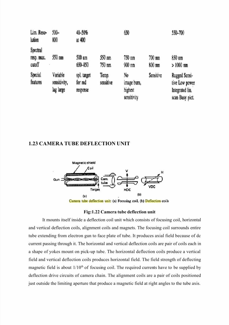
1.'( CAMERA TUE DEFLECTION UNIT
Fi$91.'' C#"er# tu7e de+lection unit
(t mounts itsel# inside a de#lection coil unit 'hich consists o# #ocusing coil horizontal
and 0ertical de#lection coils alignment coils and magnets. The #ocusing coil surrounds entire
tue etending #rom electron gun to #ace plate o# tue. (t produces aial #ield ecause o# dc
current passing through it. The horizontal and 0ertical de#lection coils are pair o# coils each in
a shape o# o%es mount on pic%Eup tue. The horizontal de#lection coils produce a 0ertical
#ield and 0ertical de#lection coils produces horizontal #ield. The #ield strength o# de#lecting
magnetic #ield is aout 11/th o# #ocusing coil. The reuired currents ha0e to e supplied
de#lection dri0e circuits o# camera chain. The alignment coils are a pair o# coils positioned
ust outside the limiting aperture that produce a magnetic #ield at right angles to the tue ais.
7/26/2019 Television and video engineering
http://slidepdf.com/reader/full/television-and-video-engineering 37/42
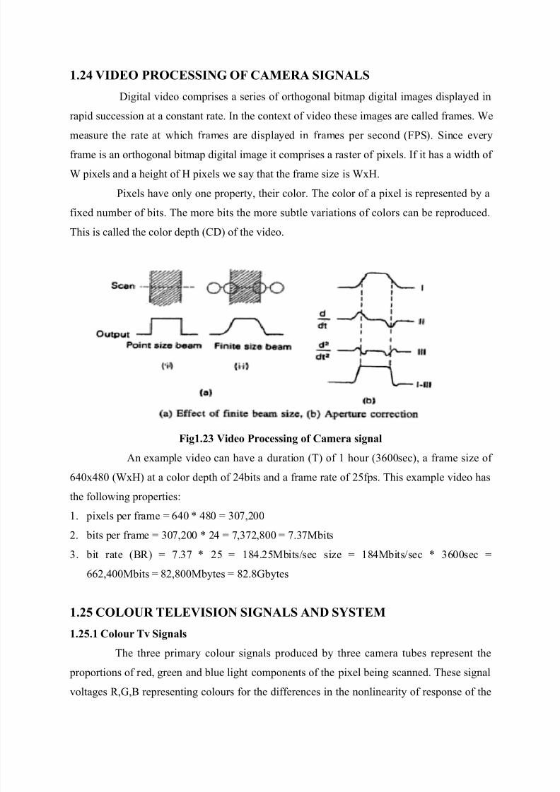
1.') VIDEO %ROCESSING OF CAMERA SIGNALS
9igital 0ideo comprises a series o# orthogonal itmap digital images displaed in
rapid succession at a constant rate. (n the contet o# 0ideo these images are called #rames. 4e
measure the rate at 'hich #rames are displaed in #rames per second :$PS;. Since e0er#rame is an orthogonal itmap digital image it comprises a raster o# piels. (# it has a 'idth o#
4 piels and a height o# H piels 'e sa that the #rame size is 4H.
Piels ha0e onl one propert their color. The color o# a piel is represented a
#ied numer o# its. The more its the more sutle 0ariations o# colors can e reproduced.
This is called the color depth :,9; o# the 0ideo.
Fi$1.'( Video %rocein$ o+ C#"er# i$n#l
An eample 0ideo can ha0e a duration :T; o# 1 hour :)6//sec; a #rame size o#
6&/&+/ :4H; at a color depth o# 2&its and a #rame rate o# 25#ps. This eample 0ideo has
the #ollo'ing properties3
1. piels per #rame G 6&/ [ &+/ G )/!2//
2. its per #rame G )/!2// [ 2& G !)!2+// G !.)!Mits
). it rate :B; G !.)! [ 25 G 1+&.25Mitssec size G 1+&Mitssec [ )6//sec G
662&//Mits G +2+//Mtes G +2.+Ntes
1.' COLOUR TELEVISION SIGNALS AND S;STEM
1.'.1 Colour Tv Si$n#l
The three primar colour signals produced three camera tues represent the
proportions o# red green and lue light components o# the piel eing scanned. These signal
0oltages NB representing colours #or the di##erences in the nonlinearit o# response o# the
7/26/2019 Television and video engineering
http://slidepdf.com/reader/full/television-and-video-engineering 38/42
camera tues and picture tue to pro0ide the gamma corrected =N=B= signals. These
gamma corrected signals NB are adusted to an aritrar 0alue o# 1V each.
These signals could e directl used #or transmission and reproduction o# picture
on a three eam colour picture tue 'ith 0er #ine NB phosphor dots deposited seuentiall
along the screen.
The colour components are represented the colour di##erence signals EXEBEX
#orming the chrominance signal 'hich can e decoded in color TV recei0er to otain NB
signal to dri0e the colour picture tue #or colour picture reproduction.
1.'.' Colour Tv S!te"
A seuential techniue #or transmitting colour di##erence signal alternatel and
comining them through a dela line s'itching under the name S*,AM 'as de0eloped in
$rance 'hile in Nerman PA- sstem 'as de0eloped in 'hich phase errors are cancelled
alternating the phase o# the colour 0ector alternatel.
(n PA- colour TV sstem 'hich 'as designed as a 0ariant o# DTS, sstem to
eliminate its susceptiilit to phase error the colour di##erence signals EX and BEX are
directl used to carr the colour in#ormation. Be#ore modulation these signals are 'eighted
#actors o# /.+!! and /.&) to produce V and ? chroma signals. 4eighting reduce the
possiilit o# o0er modulation o# the transmitter carrier in presence o# highl saturated colour
during 0er light and 0er dar% parts o# picture.
7/26/2019 Television and video engineering
http://slidepdf.com/reader/full/television-and-video-engineering 39/42
/UESTION AN5
UNIT 1
%ART A <' M#r2=
1. 4hat is aster\
2. 9e#ine aspect ratio and usti# the choice o# aspect ratio.
). 9ra' the simple loc% diagram o# TV transmitter.
&. 9ra' the simple loc% diagram o# TV recei0er.5. 4hat do ou mean scanning\
6. 4hat do ou mean rectangular scanning\
!. 4hat do ou mean horizontal scanning and 0ertical scanning\
+. 4hat are the #actors that decide the numer o# scanning lines per #rame\
. 4rite short notes on image continuit.
1/. 4rite short notes on persistence o# 0ision.
11. 4hat is #lic%er\ Ho' it can e a0oided\
12. 4hat is interlaced scanning\
1). 4h 0ertical scanning is 5/Hz in (ndian TV sstem\
1&. 4hat is the 0ertical and horizontal scanning #reuenc in interlaced scanning\
15. 4hat is the scanning periods :Both 0ertical and horizontal; in interlaced scanning\
16. Ni0e scanning seuence in interlaced scanning.
1!. 4hat do ou mean interlaced error\
1+. 4h total numer o# lines in an TV sstem must e an odd numer\
1. Ho' maimum 0ideo signal #reuenc is calculated\
7/26/2019 Television and video engineering
http://slidepdf.com/reader/full/television-and-video-engineering 40/42
2/. 4h 625 lines are there in (ndian TV sstem 'h not 62) or 62!\
21. 4hat is the and'idth needed #or snc pulses\
22. 9e#ine picture resolution.
2). 9e#ine 0ertical and horizontal resolution.
2&. 9e#ine %ell #actor.
25. 4hat is the maimum and minimum 0ideo #reuenc reuired\
26. 4hat are the characteristics o# human ee and 'hat are the #actors decided them\
2!. 4hat is 0isual acuit\ 4hat is the #actor decided it\
2+. 4rite short notes on TV ,amera.
2. Brie#l eplain the characteristics o# camera tues.
)/. 4rite short notes on camera lenses.
)1. 4rite short notes on # 7 stop numer and #ocal length o# camera lenses.
)2. 4rite short notes on photoEemissi0e and photoconducti0e e##ect.
)). 4hat is dar% current and image lag\
)&. 4rite short notes on autoE#ocus sstem.
)5. 4rite short notes on electron multiplier.
)6. 4rite short notes on #ieldEmesh image orthicon.
)!. Brie#l eplain lea% capacitor principle o# 'or%ing o# 0idicon.
)+. Ni0e the construction o# plumicon.
). Ni0e the construction o# silicon diode arra 0idicon.
&/. 4rite short notes on lens turret and zoom lens.
&1. 9ra' the #unctional loc% diagram o# monochrome TV camera.
&2. Brie#l eplain 0ideo processing o# camera signal.
&). Ni0e comparison o# camera tues.
&&. 9e#ine contrast ratio.
&5. *plain ho' the inherent smear e##ect in a 0idicon is o0ercome in a plumicon.
&6. 9e#ine compatiilit and re0erse compatiilit.
&!. 4hat are the reuirements to meet compatiilit\
&+. Brie#l eplain three color theor or 'hat is additi0e miing 8 sutracti0e miing\
&. State Nrassman=s la'.
5/. 4hat are the tristimulus 0alue o# spectral colors\
51. 9e#ine -uminance hue and saturation.
52. *plain ho' transmission o# color di##erence signals aids to compatiilit o# color TV
sstem.

7/26/2019 Television and video engineering
http://slidepdf.com/reader/full/television-and-video-engineering 41/42
5). 9ra' color circle sho'ing location and magnitude o# primar and complementar
colors.
5&. Brie#l eplain unsuitailit o# :NEX; #or color signal transmission. "r 4h :NEX;
color di##erence signal is not used\
55. 4hat is #reuenc interlea0ing\
56. 4hat is the and'idth o# color signal transmission\
5!. Brie#l eplain modulation o# color di##erence signal.
5+. 4hat is color urst\
7/26/2019 Television and video engineering
http://slidepdf.com/reader/full/television-and-video-engineering 42/42
%ART <10 M#r2=
1. 4ith neat diagram eplain the characteristics o# human ee.
2. *plain interlaced scanning.
). *plain the construction and 'or%ing o# image orthicon.
&. *plain the construction and 'or%ing o# 0idicon.
5. *plain the construction and 'or%ing o# plumicon and silicon diode arra 0idicon.
6. :a; *plain the construction and 'or%ing o# ,,9 solid state image scanner.:+;
:; ,ompare 0arious TV camera pic%Eup tues. :+;
!. :a; ,amera pic%Eup tue de#lection unit.:+;
:; 0ideo processing o# camera signal.:+;
+. :a; AutoE#ocus sstem.:+;
:; ,amera lenses.:+;
. *plain sound and picture transmission in TV sstem.
1/. Brie#l eplain 0ertical and horizontal resolution and deri0e the maimum 0ideo
signal #reuenc reuired.
11. *plain color TV camera.
12. *plain the generation and transmission o# color di##erence signals.
1). *plain the unsuitailit o# :NEX; #or color signal transmission.1&. 9e#ine X and color di##erence signal. *plain #ormation o# these #or color ar pattern
o# 'hite ello' can green magenta red lue and lac%.