Embed Size (px)
Citation preview

Testing of a Flame and Ember-
Resistant Vent Construction (Based on Draft California State Fire Marshal Interim Test Method for Evaluating the Ability of Vents to Resist Entry of Embers and Flame
Impingement)
PN# 08085
Report #08085.1
Conducted for: Vivico LLC
4443 Bennett View Drive Santa Rosa, CA 95404
TESTING CONDUCTED: NOVEMBER 25, 2008
REPORT REISSUED: JANUARY 6, 2008

Vivico LLC WFCi PN# 08085, Report No. 08085.1
Western Fire Center, Inc.
TABLE OF CONTENTS
INTRODUCTION............................................................................. 3 SUMMARY OF THE TEST METHOD ....................................................... 3 SAMPLE DESCRIPTION.................................................................... 6 PART A - EMBER PENETRATION TEST ................................................. 7 TEST OBSERVATIONS AND RESULTS ................................................... 7
Test #1: .................................................................................7
Test #2: .................................................................................7
Test #3: .................................................................................8
RESULTS AND DISCUSSION – EMBER TESTING........................................................ 9 PART B – FLAME INTRUSION TEST .................................................. 10 TEST OBSERVATIONS AND RESULTS ................................................. 10
Test #1: ............................................................................... 10
Test #2: ............................................................................... 10
Test #3: ............................................................................... 11
RESULTS AND DISCUSSION – FLAME INTRUSION TESTING ................................... 14 CONCLUSION .............................................................................. 14 SIGNATURE PAGE........................................................................ 15
Kelso, Washington Page 2 of 15

Vivico LLC WFCi PN# 08085, Report No. 08085.1
Western Fire Center, Inc.
INTRODUCTION This report documents the eave vent testing of vent samples performed by Western Fire Center, Inc. (WFCi) for Vivico LLC. The ember penetration and flame intrusion tests were performed by Howard Stacy, Mike White and Wayne Beres on November 25, 2008. The purpose of this testing was to evaluate the fire test performance characteristics of the client’s exterior eave vent specimen when subjected to specified fire and ember exposure conditions.
SUMMARY OF THE TEST METHOD The test methodology employed for the evaluation of the Vivico FireGuardVent self-closing vent construction followed the procedures described in a proposed draft interim test procedure entitled “Test Method for Evaluating the Ability of Vents to Resist Entry of Embers and Flame Impingement” submitted to the California State Marshall’s Office for review on August 29, 2008. This methodology is also under review as a draft standard in ASTM Committee E5 (Fire Standards), TG E5.14.04.
Excerpts of the test procedures from the draft interim flame and ember intrusion test are provided in the following:
4. PART A. Ember Intrusion Test
4.1 Apparatus. The ember intrusion apparatus is shown in Figures 1 and 2. It consists of an ember generation section (circular squirrel cage (tumbler) enclosed with wire) and a two-level cabinet. The vent to be tested shall be positioned on the upper level and the combustion (evaluation) material shall be positioned on the lower level. A 1-inch (25 mm) diameter pipe, with fifteen 1/8-inch (3 mm) holes, spaced at 1-inch (25 mm) intervals, shall be used as the gas diffusion burner (Figure 3). A 12-inch (300 mm) hole shall be cut into the back wall of the lower section so that air can be pulled through the chamber.
4.1.1 Pressure ports will be inserted above and below the horizontal vent separation panel (level). Pressure shall be measured in the sections above and below the vent.
4.1.2 One thermocouple (Type K, 18 ga.) shall be positioned at equal distances around the perimeter on the entering side of the vent. Temperature readings shall be taken at intervals not exceeding 1 per second.
4.2 Generation of Embers
4.2.1 Standard Class-C brands, as described in ASTM E-108 (Section 10.3.3), are used as the starting material. The squirrel cage will be loaded with eight C-brands prior to each test.
4.2.2 Prior to the test, the brands shall be conditioned in an oven at 40 to 49°C (105 to 120°F) for at least 24 hours.
Kelso, Washington Page 3 of 15

Vivico LLC WFCi PN# 08085, Report No. 08085.1
Western Fire Center, Inc.
4.2.3 Eight 7/8-inch diameter steel ball bearings shall be included in each charge of C-brands to aid in ember generation.
4.2.4 Ignition of Brands - The C-brands shall be ignited by subjecting them to the flame of a gas burner of such size that, during the process of ignition, the brands are enveloped in the burner flame for 3 minutes. The flame temperature of the igniting flame shall be 1630±50°F (888±28°C) measured 2 inches (51mm) inside the squirrel cage.
4.3 Conduct of Test
4.3.1 Load the eight 7/8-inch steel ball bearings and eight C-brands in the bottom of the cage.
4.3.2 Insert cotton material on the second shelf.
4.3.3 Ignite the gas burner and direct the flame such that it extends approximately 2 inches into the squirrel cage and impinges on the C-brands. Continue the flame impingement exposure for a period of three minutes. The apparatus door shall remain open during ignition of C-brands.
4.3.4 At the end of the three minute period:
4.3.4.1 Turn off the gas burner.
4.3.4.2 Close apparatus door.
4.3.4.3 Turn on the squirrel cage tumbler.
4.3.4.4 Turn on the exhaust fan (the wiring can be set up such that the tumbler and fan are on the same switch).
4.3.4.5 Run the tumbler until it is devoid of all portions of the C-brands.
4.3.5 Tests shall be run in triplicate.
4.4 Acceptance Criteria
4.4.1 Sustained flaming on the cotton target shall not occur.
4.4.2 The test shall be run on three representative vents. All three vents must comply with the acceptance criteria.
Note: The temperature at the entering side of the vent shall not exceed 55°C (130°F)].
5. PART B. Flame Intrusion Test
5.1 Burner. A 12 x 12 inch (300 x 300 mm) gas diffusion burner (propane or natural gas) shall be used.
5.2 Vent. Use the vent that has been selected for the test. If necessary, the vent will be reduced in size, while maintaining the same design features, to fit into the vent level in the apparatus.
5.3 Apparatus. The apparatus used to evaluate vents for flame intrusion shall be that described in SFM Standards 12-7A-1 (Exterior Wall Siding and Sheathing), and SFM 12-7A-3 (Under Eave). A diagram of the wall/eave test apparatus is shown in Figure 4. The wall opening of the holding fixture shall be enclosed with gypsum wallboard, fiber cement board, or equivalent. The ‘interior’ (attic side) of the roof vent assembly is to be open so that the flame plume from the burner will flow through the vent into the simulated attic space.
5.4 Vent Assembly. The vent shall be fitted into the noncombustible eave assembly described in 12-7A-3.7, Item 3, Test System Preparation. The horizontal soffit of the eave assembly shall be constructed of gypsum wallboard, fiber cement board, or equivalent.
Kelso, Washington Page 4 of 15

Vivico LLC WFCi PN# 08085, Report No. 08085.1
Western Fire Center, Inc.
The test vent shall be centered directly above the exterior wall vertical centerline. The distance between the top of burner and vent opening shall be 82 inches (2.1 m).
5.5 Sealing. All edges of the vent will be sealed with ceramic wool or comparable material to prevent flame penetration at the locations where the vent intersects with the noncombustible soffit material.
5.6 Video documentation. A video camera shall be positioned on the attic interior side of the vent test assembly so that any flame penetration through the vent can be viewed and documented. Another camera shall be placed to document the flame application to the vent entry opening.
5.7 Temperature measurements. Three type K (or equivalent) thermocouples (18 gauge or lighter) shall be mounted in the air space above the vent geometrical center and at its half points along the long dimension of the vent. The thermocouples shall be positioned 1.0 inch (25 mm) above the vent exit opening on the ‘attic’ side of the vent. The purpose of these thermocouples is to evaluate the effectiveness of the vent’s sealing during testing.
5.8 Conduct of Tests
5.8.1 Airflow. The flame impingement test shall be conducted under conditions of ambient airflow. Care shall be taken to assure that the plume of flame issuing from the burner is as close to vertical as possible and impacts directly on the test vent.
5.8.2 Number of tests. Conduct the tests on three replicate vents of the same design and size.
5.8.3 Burner configuration. The burner will be centered with respect to the vent orientation in the soffit and 0.75 inches (20 mm) from the wall
5.8.4 Burner output verification. Without the vent in place, adjust the burner for 300 kW ± 15 kW. Extinguish the burner.
5.8.5 Procedure
5.8.5.1 Ignite the burner, controlling for a constant 300 ± 15 kW output.
5.8.5.2 Continue the exposure until flame penetration of the vent occurs, a maximum temperature of 325°C (617°F) is exceeded by any single thermocouple for a period of 6 seconds or more, or for a 10-minute period.
5.8.5.3 Tests shall be run in triplicate.
5.9 Observations. Note the time and duration of flame penetration.
5.10 Conditions of Acceptance
5.10.1 The test shall be run on three representative vents. All three vents must comply with the acceptance criteria.
5.10.2 No flame shall be observed on the non-fire side of the vent for a period in excess of 10 seconds.
5.10.3 The maximum temperature of any single thermocouple shall not exceed 325°C (617°F) for a period in excess of 6 seconds.
Kelso, Washington Page 5 of 15

Vivico LLC WFCi PN# 08085, Report No. 08085.1
Western Fire Center, Inc.
SAMPLE DESCRIPTION Sample FireGuardVent test samples were delivered to WFCi by the client for testing. The test vents measured 3-1/4” wide and 14” long overall, with the opening of the vent measuring 2-5/16” wide and 13-1/8” long. The exit side of the vent assembly is fitted with No. 18x14 steel mesh screen.
The vent design includes a damper blade pivotally connected to and disposed within the vent housing, which is held in an open position by a temperature-sensitive fusible link. Two permanent magnets provide the force for driving the damper blade into a closed and locked position. A first magnet disposed on the side of the vent housing and a second magnet on the damper blade is oriented with opposing polarities when the damper blade is held in the open position. A third magnet situated proximate to the back of the vent housing is oriented so as to attract the magnet located on the damper blade. When the fusible link is broken by high temperatures, the first magnet propels the damper blade toward the closed position, and the third magnet attracts the damper blade to assist in putting it into a fully closed position. Mechanical locks supplement the secure closure of the damper blade.
Kelso, Washington Page 6 of 15

Vivico LLC WFCi PN# 08085, Report No. 08085.1
PART A - EMBER PENETRATION TEST The ember penetration tests were performed on November 25, 2008. Prior to each test, the exhaust blower was set at its lowest setting which produced a pressure differential of 0.10” H2O across the vent test item in the test chamber. The brand tumbler was set at 30-35 revolutions per minute. Eight conditioned “C” brands were exposed to the ignition burner for 3 minutes prior to the start of the exposure. The ember target consisted of a 12” wide by 20” long cotton fiber “batt” (two 6” wide pieces laid side by side) weighing between 67-82 g.
TEST OBSERVATIONS AND RESULTS
Test #1: Time mm:ss Observation
00:00 Ignite burner, expose brands to flame for 3 minutes 03:00 Terminate burner flame, activate blower, close cabinet
door, initiate ember exposure, 03:00 to 08:00 Small embers pass through vent, some glow at points of
ember contact with cotton target, no ignition 0:08:00 Ember generation complete, no ignition of cotton target,
PASS Post Fire Exposure: Slight charring/discoloration at points of ember contact
evenly distributed across cotton target Date 11/25/08
Cabinet temperature - vent entry side
94°C at T= 0, 126°C at T= 50s, 100°C at T= 8 minutes
Laboratory Temp/Humidity 18°C/37%
Test #2: Time mm:ss Observation
00:00 Ignite burner, expose brands to flame for 3 minutes 03:00 Terminate burner flame, activate blower, close cabinet
door, initiate ember exposure, 03:00 to 08:00 Small embers pass through vent, some glow at points of
ember contact with cotton target, no ignition 0:08:00 Ember generation complete, no ignition cotton target,
PASS Post Fire Exposure: Slight charring/discoloration at points of ember contact
evenly distributed across cotton target Date 11/25/08
Cabinet temperature - vent entry side
103°C at T= 0, 224°C at T= 50s, 99°C at T= 8 minutes
Laboratory Temp/Humidity 18°C/37%
Western Fire Center, Inc. Kelso, Washington Page 7 of 15

Vivico LLC WFCi PN# 08085, Report No. 08085.1
Test #3:
Time mm:ss Observation
00:00 Ignite burner, expose brands to flame for 3 minutes 03:00 Terminate burner flame, activate exhaust blower, close
cabinet door, initiate ember exposure, 03:00 to 08:00 Small embers pass through vent, some glow at points of
ember contact with cotton target, no ignition 0:08:00 Ember generation complete, no ignition cotton target,
PASS Post Fire Exposure: Slight charring/discoloration at points of ember contact
evenly distributed across cotton target Date 11/25/08
Cabinet temperature - vent entry side
104°C at T= 0, 224°C at T= 50s, 101°C at T= 8 minutes
Laboratory Temp/Humidity 18°C/37%
Immediately prior to ember exposure: Brands exposed to igniter for 3 minutes
Western Fire Center, Inc. Kelso, Washington Page 8 of 15
Vivico LLC WFCi PN# 08085, Report No. 08085.1
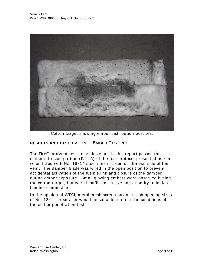
Cotton target showing ember distribution post test
RESULTS AND DISCUSSION – EMBER TESTING The FireGuardVent test items described in this report passed the ember intrusion portion (Part A) of the test protocol presented herein, when fitted with No. 18x14 steel mesh screen on the exit side of the vent. The damper blade was wired in the open position to prevent accidental activation of the fusible link and closure of the damper during ember exposure. Small glowing embers were observed hitting the cotton target, but were insufficient in size and quantity to initiate flaming combustion.
In the opinion of WFCi, metal mesh screen having mesh opening sizes of No. 18x14 or smaller would be suitable to meet the conditions of the ember penetration test.
Western Fire Center, Inc. Kelso, Washington Page 9 of 15
Vivico LLC WFCi PN# 08085, Report No. 08085.1 PART B – FLAME INTRUSION TEST
TEST OBSERVATIONS AND RESULTS
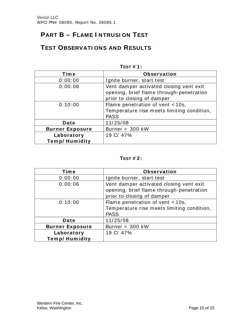
TEST #1: Time Observation
0:00:00 Ignite burner, start test 0:00:08 Vent damper activated closing vent exit
opening, brief flame through-penetration prior to closing of damper
0:10:00 Flame penetration of vent <10s, Temperature rise meets limiting condition, PASS
Date 11/25/08 Burner Exposure Burner = 300 kW
Laboratory Temp/Humidity
19 C/ 47%
TEST #2:
Time Observation 0:00:00 Ignite burner, start test 0:00:06 Vent damper activated closing vent exit
opening, brief flame through-penetration prior to closing of damper
0:10:00 Flame penetration of vent <10s, Temperature rise meets limiting condition, PASS
Date 11/25/08 Burner Exposure Burner = 300 kW
Laboratory Temp/Humidity
19 C/ 47%
Western Fire Center, Inc. Kelso, Washington Page 10 of 15

Vivico LLC WFCi PN# 08085, Report No. 08085.1
TEST #3:
Time Observation 0:00:00 Ignite burner, start test 0:00:07 Vent damper activated, closing vent exit
opening, brief flame through-penetration prior to closing of damper
0:10:00 Flame penetration of vent <10s, Temperature rise meets limiting condition, PASS
Date 11/25/08 Burner Exposure Burner = 300 KW
Laboratory Temp/Humidity
19 C/ 47%
Vent Exit Temperature Data Test 1
Flame Intrusion Test #1
0
50
100
150
200
250
300
350
-60 40 140 240 340 440 540 640 740
Time (s)
Deg
rees
C TC 1TC 2TC 3
Western Fire Center, Inc. Kelso, Washington Page 11 of 15
Vivico LLC WFCi PN# 08085, Report No. 08085.1
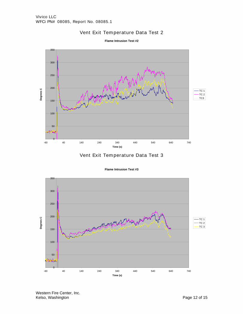
Vent Exit Temperature Data Test 2
Flame Intrusion Test #2
0
50
100
150
200
250
300
350
-60 40 140 240 340 440 540 640 740
Time (s)
Deg
rees
C TC 1TC 2TC3
Vent Exit Temperature Data Test 3
Flame Intrusion Test #3
0
50
100
150
200
250
300
350
-60 40 140 240 340 440 540 640 740
Time (s)
Deg
rees
C TC 1TC 2TC 3
Western Fire Center, Inc. Kelso, Washington Page 12 of 15

Vivico LLC WFCi PN# 08085, Report No. 08085.1
Vent in soffit position prior to flame exposure
Flame intrusion exposure
Western Fire Center, Inc. Kelso, Washington Page 13 of 15

Vivico LLC WFCi PN# 08085, Report No. 08085.1
Vent exit side during flame intrusion exposure
RESULTS AND DISCUSSION – FLAME INTRUSION TESTING No flame was observed on the non-fire side of the vents for a period in excess of 10 seconds in any of the three replicate tests. Likewise, the maximum temperature of any single thermocouple on the unexposed side of the vents did not exceed the limiting condition of 325°C for a period in excess of six seconds. Activation of the fusible link occurred within the first 8 seconds of flame exposure in all three cases. The vent construction therefore met the limiting conditions of Part B of the proposed test method.
CONCLUSION
The FireGuardVent construction as described in this report meets the limiting criteria established in Parts A and B of the Draft California State Fire Marshal Interim Test Method for Evaluating the Ability of Vents to Resist Entry of Embers and Flame Impingement.
Western Fire Center, Inc. Kelso, Washington Page 14 of 15

Vivico LLC WFCi PN# 08085, Report No. 08085.1
SIGNATURE PAGE
Reviewed and approved,
Howard Stacy
Director, Testing Services
WESTERN FIRE CENTER AUTHORIZES THE CLIENT NAMED HEREIN TO
REPRODUCE THIS REPORT ONLY IF REPRODUCED IN ITS ENTIRETY
The test specimen identification is as provided by the client and WFCi accepts no responsibilities for any inaccuracies therein. WFCi did not select the specimen and has not verified the composition, manufacturing techniques or quality assurance procedures.
Western Fire Center, Inc. Kelso, Washington Page 15 of 15