Embed Size (px)
Citation preview
TF03 UART/CAN Product Manual V1.2.2 Benewake(Beijing)Co., Ltd
Page1
TF03 Long-Distance LiDAR
UART/CAN
Product Manual V1.2.2

TF03 UART/CAN Product Manual V1.2.2 Benewake(Beijing)Co., Ltd
Page2
Specified Product
Product model: TF03 UART/CAN
Product Name: Long-Distance LiDAR
Manufacturer
Company name: Benewake (Beijing) Co., Ltd.
Address: NO.28 Xinxi Road, Haidian District, Beijing, PRC
Copyright
The Copyright of this document is protected. All the rights involved herein belong to
Benewake (Beijing) Co., Ltd. Any copy activity of this document, no matter in whole or in part,
should be in conformity of the Copyright Law. The actives of modification, omission or translation
of this document are not allowed unless a written permission from Benewake (Beijing) Co., Ltd.
All rights reserved © Benewake (Beijing) Co., Ltd.

TF03 UART/CAN Product Manual V1.2.2 Benewake(Beijing)Co., Ltd
Page3
Foreword
Dear users:
Thanks for choosing Benewake products, and it’s our pleasure to help you to solve any
technical question.
For the purpose of offering a better operation experience to you, we hereby write this manual
for an easier and simpler operation of our product, hoping to better solve the common problems
you maybe meet. Please contact us if you have any questions.( [email protected])
This operation manual covers the product operation introduction and common problem
solutions, but it is really hard to cover all the problems you maybe meet. So if you have any further
questions or problems, please feel free to consult our technical support service
([email protected]). We will do our best to solve any problem related to the product. If you
have any other good advice or suggestions, welcome to visit our official website and offer us your
feedback there (http://en.benewake.com/support), and we are looking forwards to your
participation.
We are Benewake who dedicated to making the best “Robotic Eyes” worldwide!

TF03 UART/CAN Product Manual V1.2.2 Benewake(Beijing)Co., Ltd
Page4
Catalog
1 ATTENTIONS ....................................................................................................................................... 6
1.1 ABOUT THIS DOCUMENT ........................................................................................................................ 6
1.2 USAGE OF PRODUCT.............................................................................................................................. 6
1.3 CONDITIONS WITH POTENTIAL PRODUCT FAILURE ........................................................................................ 6
2 PRODUCT INTRODUCTION ................................................................................................................... 7
2.1 APPEARANCE OVERVIEW ........................................................................................................................ 7
2.2 PRODUCT STRUCTURE ........................................................................................................................... 7
2.3 PRINCIPLE OF MEASUREMENT ................................................................................................................. 7
2.4 DETECTION ANGLE DESCRIPTIONS ............................................................................................................. 8
3 PHYSICAL INTERFACE ........................................................................................................................... 9
3.1 DESCRIPTION OF LINE SEQUENCE AND CONNECTION ...................................................................................... 9
3.2 ELECTRICAL CHARACTERISTICS ................................................................................................................ 10
4 COMMUNICATION INTERFACE AND DATA FORMAT ............................................................................. 11
4.1 UART INTERFACE ............................................................................................................................... 11
4.2 CAN BUS ........................................................................................................................................ 12
4.3 DESCRIPTIONS ON PARAMETER CONFIGURATION ......................................................................................... 13
4.3.1 FUNCTION OVERVIEW .................................................................................................................................. 13
4.3.2 COMMANDS ............................................................................................................................................... 13
4.3.3 INSTRUCTIONS OF COMMAND EDITING ............................................................................................................ 15
5 QUICK TEST PROCEDURE ................................................................................................................... 15
5.1 REQUIRED TOOLS OF PRODUCT TEST ....................................................................................................... 15
5.2 TEST PROCEDURE ................................................................................................................................ 16

TF03 UART/CAN Product Manual V1.2.2 Benewake(Beijing)Co., Ltd
Page5
5.3 TEST EXAMPLE ................................................................................................................................... 17
5.3.1 TEST RANGE WITH DIFFERENT REFLECTIVITY .................................................................................................... 17
5.3.2 ACCURACY OF DIFFERENT MATERIALS ............................................................................................................. 17
6 CONFIGURATION SOFTWARE OF TF03 ................................................................................................ 18
7 FAILURE REASONS AND TROUBLESHOOTING ...................................................................................... 19
8 FAQ .................................................................................................................................................. 20
ATTACHMENT 1: REFLECTIVITY OF DIFFERENT MATERIALS ........................................................................ 21

TF03 UART/CAN Product Manual V1.2.2 Benewake(Beijing)Co., Ltd
Page6
1 Attentions
1.1 About this Document
This Manual provides information necessary for the use of this product.
Please read this Manual carefully before using this product and make sure that you have
fully understood its contents.
1.2 Usage of Product
This product can only be maintained by qualified professionals and only the original spare
parts can be used to ensure its performance and safety.
The working temperature of the product is -25°C~60°C; please do not use it beyond this
temperature range, so as to avoid risks.
The storage temperature of the product is -40°C~85°C; please do not store it beyond this
temperature range, so as to avoid risks.
Do not open its enclosure for assembly or maintenance beyond this Manual; otherwise,
it will affect the product performance.
Do not twist the cable forcefully, so as to avoid damage to product.
The product can’t be aimed directly to the sun or another TF03, so as to avoid damage
the detector by strong light. If there is such an application, please contact our technician.
1.3 Conditions with Potential Product Failure
When the product transmitter and receiver lens are covered by dirt, there will be a risk of
failures. Please keep the lens clean.
The product will have a risk of failure when immersed completely in water. Do not use it
underwater.
When detecting objects with high reflectivity, such as mirrors and smooth tiles, the
product may have a high risk of failures.
TF03 UART/CAN Product Manual V1.2.2 Benewake(Beijing)Co., Ltd
Page7
2 Product Introduction
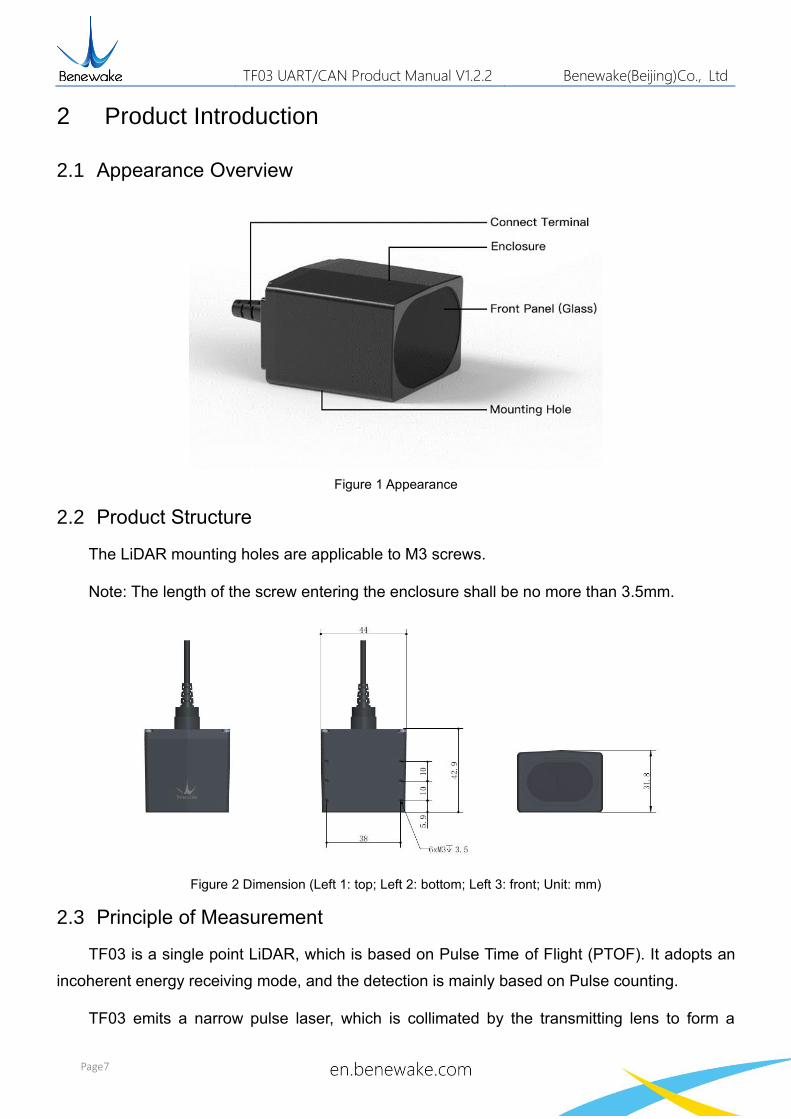
2.1 Appearance Overview
Figure 1 Appearance
2.2 Product Structure
The LiDAR mounting holes are applicable to M3 screws.
Note: The length of the screw entering the enclosure shall be no more than 3.5mm.
Figure 2 Dimension (Left 1: top; Left 2: bottom; Left 3: front; Unit: mm)
2.3 Principle of Measurement
TF03 is a single point LiDAR, which is based on Pulse Time of Flight (PTOF). It adopts an
incoherent energy receiving mode, and the detection is mainly based on Pulse counting.
TF03 emits a narrow pulse laser, which is collimated by the transmitting lens to form a

TF03 UART/CAN Product Manual V1.2.2 Benewake(Beijing)Co., Ltd
Page8
collimated light, which enters the receiving system after being reflected by the measured target
and is focused on the APD detector by the receiving lens. The time between the transmitted signal
and the received signal is calculated through the circuit amplification and filtering, and the distance
between TF03 and the measured target can be calculated through the speed of light.
Figure 3 Principle of measurement
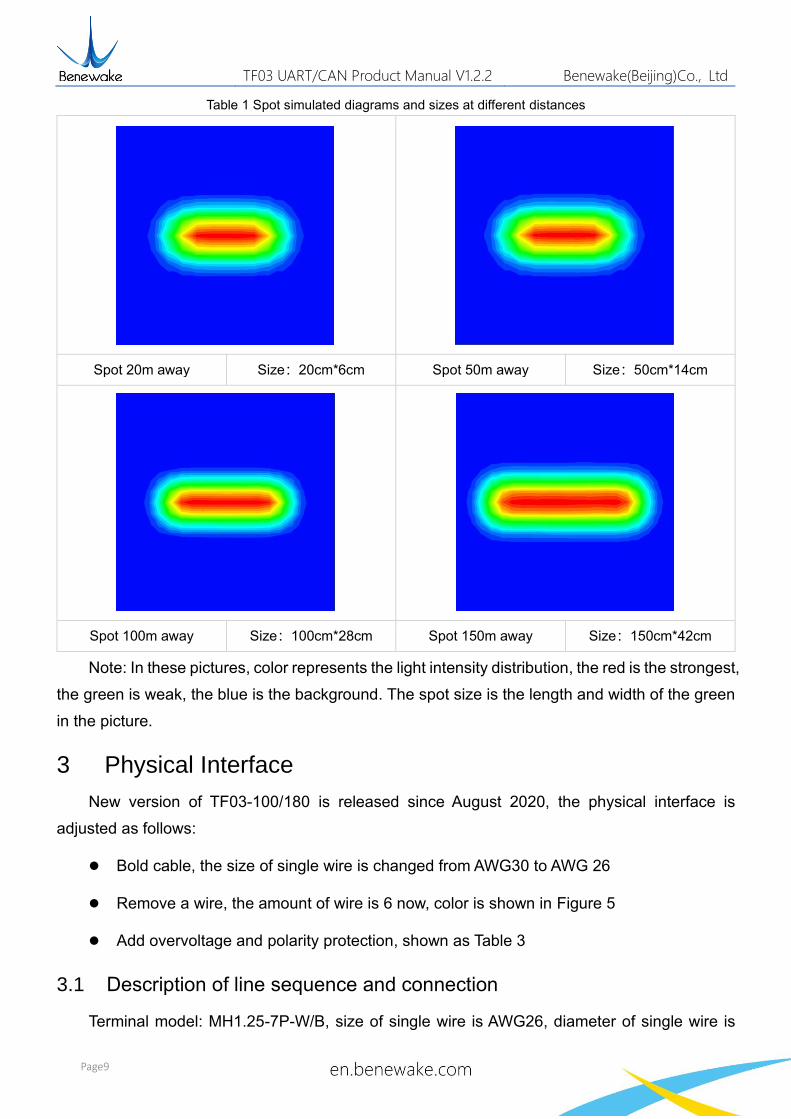
2.4 Detection angle descriptions
TF03 has a 0.5 degree detection angle and rectangular light spot, see Figure 4 for simulated
diagrams of the light spot. Therefore, at different distances, the spot size, namely detecting range,
is different as shown in Table 1.
Note: The side length of common objects detected should be greater than that of the
detection range of TF03; When the side length of the detected object is less than that of the
detection range, the LiDAR effective range will be reduced
Figure 4 Detection angle of TF03
Laser
Pulse timing
Module
TF03 UART/CAN Product Manual V1.2.2 Benewake(Beijing)Co., Ltd
Page9
Table 1 Spot simulated diagrams and sizes at different distances
Spot 20m away Size:20cm*6cm Spot 50m away Size:50cm*14cm
Spot 100m away Size:100cm*28cm Spot 150m away Size:150cm*42cm
Note: In these pictures, color represents the light intensity distribution, the red is the strongest,
the green is weak, the blue is the background. The spot size is the length and width of the green
in the picture.
3 Physical Interface
New version of TF03-100/180 is released since August 2020, the physical interface is
adjusted as follows:
⚫ Bold cable, the size of single wire is changed from AWG30 to AWG 26
⚫ Remove a wire, the amount of wire is 6 now, color is shown in Figure 5
⚫ Add overvoltage and polarity protection, shown as Table 3
3.1 Description of line sequence and connection
Terminal model: MH1.25-7P-W/B, size of single wire is AWG26, diameter of single wire is

TF03 UART/CAN Product Manual V1.2.2 Benewake(Beijing)Co., Ltd
Page10
0.404mm, cross-sectional area is 0.129mm2.
Figure 5 New Line Sequence of TF03
Table 2 Pin functions and connection instructions of TF03
No. Color Pin Function
1 Red VCC Voltage Input
2 White CAN_L CAN
3 Green CAN_H CAN
4 N/A N/A N/A
5 Blue TTL_RXD UART receiver
6 Brown TTL_TXD UART transmitter
7 Black GND GND
Note: If UART is used, the TTL_RXD and TTL_TXD must be connected and not allowed to
be left floating, So as not to be affected by electromagnetic interference.
3.2 Electrical Characteristics
New version has overvoltage and polarity protection.
Table 3 Main electrical parameters
Parameter Typical value
Supply voltage 5V~24V
Average current ≤150mA
Average power consumption ≤1W
Overvoltage protection 300V
Polarity protection 200V

TF03 UART/CAN Product Manual V1.2.2 Benewake(Beijing)Co., Ltd
Page11
4 Communication interface and Data format
The standard version of TF03 supports UART and CAN communication interface. The default
interface is UART. If necessary, the CAN mode can be set by sending command. Two interfaces
cannot output simultaneously.
4.1 UART Interface
TF03 adopts UART interface, LVTTL level is 0~3.3V. The specific communication interface is
shown as below.
Table 4 Communication interface of UART
Item Parameter
Communication interface UART
Baud rate 115200
Data bit 8
Stop bit 1
Parity None
The output data (hexadecimal numbers) of TF03 is shown in Table 5. Each data frame
consists of 9 bytes and the data contains the distance and signal strength1 information.
Table 5 TF03 UART data format
Data bit Definition Description
Byte0 Frame header 0x59
Byte1 Frame header 0x59
Byte2 DIST_L DIST low 8-bits
Byte3 DIST_H DIST high 8-bits
Byte4 Strength_L Signal strength low 8-bits
Byte5 Strength_H Signal strength high 8-bits
Byte6 Reserved bit /
Byte7 Reserved bit /
1 New version of TF03 adds strength information. Strength value is between 0 and 3500, threshold of strength is 40, when
strength is lower than 40, dist will output maximum value. When strength is between 40 and 1200, dist is more reliable. When
there is a high reflectivity object, strength will be over 1500.
TF03 UART/CAN Product Manual V1.2.2 Benewake(Beijing)Co., Ltd
Page12
Byte8 Checksum Low 8 bits of Checksum bit.
Checksum = Byte0 + Byte2+…+Byte7
4.2 CAN BUS
The CAN communication protocol of TF03 can be customized according to the customer's
demand. The CAN baud rate and ID and frame format can be modified. The contents of the
interface are shown in Table 6.
Table 6 Communication interface of CAN
Item Content
Communication protocol CAN
Baud rate 1M
Receive ID 0x3003
Transmit ID 0x3
Frame format The default transmit frame is standard frame.
Receive frame supports standard and extended frame.
The output data (hexadecimal numbers) of TF03 CAN is shown in Table 7. Each data frame
consists of 6 bytes and the data contains the distance and signal strength2 information.
Table 7 TF03 CAN data format
Data bit Definition Description
Byte0 DIST_L DIST low 8-bits
Byte1 DIST_H DIST high 8-bits
Byte2 Strength_L Signal strength low 8-bits
Byte3 Strength_H Signal strength high 8-bits
Byte4 Reserved bit /
Byte5 Reserved bit /
2 Under CAN interface, when the frame rate is under 1000Hz, TF03 can output DIST and Strength at the same time, but
when the frame rate is over 1000Hz, TF03 can only output DIST.

TF03 UART/CAN Product Manual V1.2.2 Benewake(Beijing)Co., Ltd
Page13
4.3 Descriptions on parameter configuration
4.3.1 Function Overview
To meet the demand of different customers, parameters can be set by yourselves.
Parameters, such as data format, frame rate could be changed by sending command. Parameter
will be stored in flash after configured successfully and customers don’t need to configure again
when restart.
Please change the parameter according to certain demands and do not frequently try
irrelevant instructions. Please configure the product according to the demands of the manual and
never send unstated command.
The Format of Command is:
Byte Definition Description
Byte0 Head Fixed to 0x5A
Byte1 Len The length of the entire instruction frame (unit: Byte)
Byte2 ID Identifies the function of each instruction
Byte3~ByteN-2 Payload Different meanings and lengths in different ID
instruction frames
ByteN-1 Check sum the lower 8 bits of the Len-1 byte data
4.3.2 Commands
Table 8 Commands list of TF03
Function Command Response Remark Default setting
Obtain firmware version
5A 04 01 5F 5A 07 01 V1 V2 V3 SU The version number V3.V2.V1 SU is check sum
/
System reset 5A 04 02 60 Success: 5A 05 02 00 61 Fail: no response over 1s
/ /
Frame rate3 5A 06 03 LL HH SU Success: 5A 06 03 LL HH SU Fail: no response over 1s
/ 100fps
3 New version of TF03 can only support (1~9) *10N, N values for 0, 1, 2, 3. If other value is set, TF03 will set it to 100Hz. If
10000Hz is necessary, please contact our technician.

TF03 UART/CAN Product Manual V1.2.2 Benewake(Beijing)Co., Ltd
Page14
Output switch Enable: 5A 05 07 01 67 Disable: 5A 05 07 00 66
Success: same as downward command Fail: no response over 1s
/ Enable
Trigger command
5A 04 04 62 Data frame / /
Output format 5A 05 05 LL SU Success: 5A 05 05 LL SU Fail: no response over 1s
LL: format shown as below, 00: ASCII (Reserved) 01: Binary output
Binary output
UART baud rate4 5A 08 06 H1 H2 H3 H4 SU
Success: 5A 08 06 H1 H2 H3 H4 SU Fail: no response over 1s
See chapter 4.3.3 115200
Enable checksum
Enable: 5A 05 08 01 68 Disable: 5A 05 08 00 67
Success: same as command Fail: no response over 1s
/ Enable
Restore factory settings
5A 04 10 6E Success: 5A 05 10 00 6F Fail: 5A 05 10 ER SU
Fail(when ER is not 0) /
Save settings 5A 04 11 6F Success: 5A 05 11 00 70 Fail: 5A 05 11 ER SU
same as above /
Over range threshold value
5A 06 4F LL HH SU Success: 5A 05 4F 00 AE Fail: no response over 1s
Unit: cm See chapter 4.3.3
18000
Transmit CAN ID 5A 08 50 H1 H2 H3 H4 SU
Success: 5A 05 50 00 AF Fail: no response over 1s
See chapter 4.3.3 Please configure the legal CAN ID. Unexpected results may occur for illegal ID
0x3
Receive CAN ID 5A 08 51 H1 H2 H3 H4 SU
Success: 5A 05 51 00 B0 Fail: no response over 1s
See chapter 4.3.3 Please configure the legal CAN ID. Unexpected results may occur for illegal ID
0x3003
CAN baud rate5 5A 08 52 H1 H2 H3 H4 SU
Success: 5A 05 52 00 B1 Fail: no response over 1s
See chapter 4.3.3 1000000
CAN transmit frame type
Standard frame: 5A 05 5D 00 BC Extended frame: 5A 05 5D 01 BD
Success: 5A 05 5D 00 BC Fail: no response over 1s
/ Standard frame
4 Baud rate of UART can be set to 9600, 14400, 19200, 38400, 56000, 57600, 115200, 128000, 230400, 256000, 460800,
500000, 512000, 600000, 750000, 921600 and 1000000, if other value is set, TF03 will set it to 115200.
5 Baud rate of CAN interface can be set to 1M, 800K, 666K, 500K, 400K, 250K, 200K, 125K, 100K, 83330, 80000, 66660,
50000, 40000, 33330, 20000, if other value is set, TF03 will set it to 1M.
TF03 UART/CAN Product Manual V1.2.2 Benewake(Beijing)Co., Ltd
Page15
Communication interface
UART: 5A 05 45 01 A5 CAN: 5A 05 45 02 A6
Success: 5A 05 45 00 A4 Fail: no response over 1s
/ UART
Rain-fog algorithm
Enable: 5A 05 64 00 C3 Disable: 5A 05 64 01 C4
Success: 5A 05 64 00 C3 Fail: no response over 1s
/ Enable
Offset configuration6
5A 06 69 LL HH SU Success: 5A 05 69 00 C8 Fail: no response over 1s
Unit: cm See chapter 4.3.3
0
4.3.3 Instructions of command editing
To send certain command to TF03, these steps should be followed:
⚫ Change value of parameter to HEX
⚫ Put the HEX value to certain command
⚫ Calculate the checksum, put low 8-bits into command
For example, changing the baud rate to 460800, first, changing 460800 to HEX, we can get
0x00 07 08 00, then we can get this command-5A 08 06 00 08 07 00 77.
5 Quick Test Procedure
5.1 Required Tools of Product Test
Note: the product package contains only TF03 and factory certificate, other accessories are
prepared by yourself. If you need TTL-USB convert board, please contact sales or technical
support.The UART version needs a TTL-USB board when connected with computer. Tools and
method are shown as below.
Table 9 Tools of test
TF03(UART) TTL-USB Board USB Cable PC TF display
application
6 “Offset configuration” can be used for secondary calibration of distance, for example, when dist is 195cm and you want
LiDAR outputs 200cm, you can set offset value to 5cm. This function is supported from v1.11.3 firmware version.

TF03 UART/CAN Product Manual V1.2.2 Benewake(Beijing)Co., Ltd
Page16
5.2 Test procedure
1)Download the TF display application
Please download the TF display application from http://en.benewake.com/support
Note: Please close the antivirus software before unpacking the TF display application,
otherwise the files will be deleted as viruses. The TF display application currently only supports
running on the Windows system. See Attachment 1: Instruction of TF Series PC Display Software.
2)Connecting
Figure 6 Diagram of connection
As Figure 6 shown, connect 『TF03』 and 『TTL- USB board』 and 『USB cable』, ensure
no looseness, then connect 『USB cable』with 『computer』.
3)TF display software connection and reading
Figure 7 The interface of TF display software
A
B
C
D

TF03 UART/CAN Product Manual V1.2.2 Benewake(Beijing)Co., Ltd
Page17
As shown in Figure 7, test steps are shown as below:
➢ Open the TF display application
➢ Select product model『TF03』 in area A
➢ Select serial port number in area B.
➢ Click『CONNECT』to establish the communication.
➢ After connected successfully, continuous data curve will be shown in the area C 『TIME
LINE CHART』 and area D 『REAL TIME DATA』 will display the current distance (Unit:
cm) and frame rate (Effective Points).
5.3 Test Example
5.3.1 Test Range with Different Reflectivity
As shown in Figure 8, red and blue curves represent the relationship between range
performance of TF03-180 and reflectivity of the target under different ambient light situation.
Figure 8 The relationship between range performance of TF03-180 and reflectivity
5.3.2 Accuracy of Different Materials
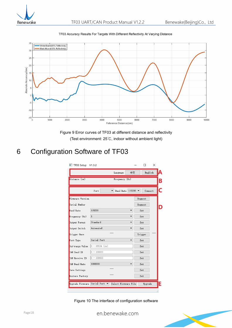
The accuracy of TF03 at different distances and reflectivity is shown in Figure 9. Two typical
background boards(black and white) are selected. The reflectivity of whiteboard is 90% and
blackboard is 10%.
TF03 UART/CAN Product Manual V1.2.2 Benewake(Beijing)Co., Ltd
Page18
Figure 9 Error curves of TF03 at different distance and reflectivity
(Test environment: 25℃, indoor without ambient light)
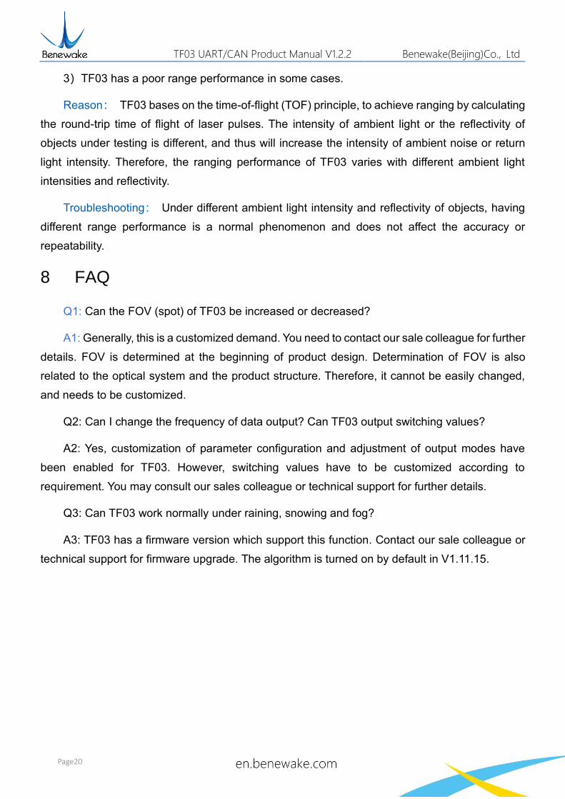
6 Configuration Software of TF03
Figure 10 The interface of configuration software
V1.3.2

TF03 UART/CAN Product Manual V1.2.2 Benewake(Beijing)Co., Ltd
Page19
Interface of configuration software is shown above.
1) After TF03 is connected to the computer, select the correct serial port number and baud
rate in Zone C manually and click the 『Connect』 button to establish communication
between the software and TF03.
2) After communication is established successfully, zone B will display the distance and
frequency of data. When no data is received over two seconds, the distance and
frequency display will disappear.
3) Zone D is dedicated to function configuration and its third column lists the buttons for
sending instructions. After clicking such buttons, the configuration software will send
commands and wait for reply from TF03. When no reply is received for a long time, 『No
Response』will be displayed on the right side of the instruction-sending buttons. Please
note that in order to ensure that TF03 reply instructions can be obtained normally, lower
the『frame rate』or set the『output mode』as『instruction trigger』before configuration.
If the changed parameters need to be saved, click 『Save Configuration』before power
down TF03.
4) Zone E is dedicated to firmware upgrade, BootLoader can be used to upgrade the
firmware.
7 Failure reasons and troubleshooting
1)Under normal operation, TF03 sometimes will output 18000(cm).
Reasons:The actual distance measured is beyond the range of TF03, TF03 will output 18000.
Troubleshooting:Treat 18000 as an exception value. When you receive 18000 from TF03,
don't adopt this data.
2)No data output after TF03 is connected to the TF display application.
Reason Ⅰ:The computer uses and operating system other than Windows.
Troubleshooting : Currently, the TF display application can only support the Windows
operating system. Use a computer with the Windows system installed.
Reason Ⅱ: Poor connection between TF03 and computer.
Troubleshooting: Please confirm that TF03 is correctly and reliably connected to the
computer, and ensure that the cables and adapter board work properly.
TF03 UART/CAN Product Manual V1.2.2 Benewake(Beijing)Co., Ltd
Page20
3)TF03 has a poor range performance in some cases.
Reason: TF03 bases on the time-of-flight (TOF) principle, to achieve ranging by calculating
the round-trip time of flight of laser pulses. The intensity of ambient light or the reflectivity of
objects under testing is different, and thus will increase the intensity of ambient noise or return
light intensity. Therefore, the ranging performance of TF03 varies with different ambient light
intensities and reflectivity.
Troubleshooting: Under different ambient light intensity and reflectivity of objects, having
different range performance is a normal phenomenon and does not affect the accuracy or
repeatability.
8 FAQ
Q1: Can the FOV (spot) of TF03 be increased or decreased?
A1: Generally, this is a customized demand. You need to contact our sale colleague for further
details. FOV is determined at the beginning of product design. Determination of FOV is also
related to the optical system and the product structure. Therefore, it cannot be easily changed,
and needs to be customized.
Q2: Can I change the frequency of data output? Can TF03 output switching values?
A2: Yes, customization of parameter configuration and adjustment of output modes have
been enabled for TF03. However, switching values have to be customized according to
requirement. You may consult our sales colleague or technical support for further details.
Q3: Can TF03 work normally under raining, snowing and fog?
A3: TF03 has a firmware version which support this function. Contact our sale colleague or
technical support for firmware upgrade. The algorithm is turned on by default in V1.11.15.

TF03 UART/CAN Product Manual V1.2.2 Benewake(Beijing)Co., Ltd
Page21
Attachment 1: Reflectivity of Different Materials
The reflectivity of different materials is listed below, ranging from low to high. According to
the test target and the corresponding reflectivity, we can measure whether the range of TF03 and
other parameters meet the requirements.
No. Materials Reflectivity
1 black foam rubber 2.4%
2 black cloth 3%
3 black rubber 4%
4 Coal (varies from coal to coal) 4~8%
5 Black car paint 5%
6 Black paper 10%
7 opaque black plastic 14%
8 Clean rough board 20%
9 newspapers 55%
10 translucent plastic bottles 62%
11 packing case cardboard 68%
12 Clean pine 70%
13 opaque white plastic 87%
14 white card 90%
15 Kodak standard whiteboard 100%
16 Unpolished white metal surface 130%
17 Shiny light metal surface 150%
18 stainless steel 200%
19 Reflective board, reflective adhesive tape >300%
C
on
tac
t
Headquarters:
400-880-9610
[email protected] [email protected]
Technical support:


![[PPT]UART and UART Driver - University at Buffalobina/cse321/fall2009/UARTDriver.ppt · Web viewUART and UART Driver B. Ramamurthy * UART UART: Universal Asynchronous Receiver/Transmitter](https://img.pdfslide.net/doc/110x75/5b2ab3637f8b9a55068b752f/pptuart-and-uart-driver-university-at-binacse321fall2009uartdriverppt.jpg)