Embed Size (px)
Citation preview

A direct replacement in every way
It may look different because of the process,UltraSTEEL™
but is a direct replacement for BS compliantUltraSTRUT™
41x41 and 41x21 strut channel sections in 2.5mm
It is light duty and fits all existing ancillary components
Being lighter, it's easier to handle, lift and transport, so it helpsreduce installation costs.
We provide plain, and slotted configurations in hot dipgalvanised material, so there’s a strut for all your applications
All this means, that when selecting you willUltraSTRUT™
require less steel for the same performance, which is good foryou and good for the environment.
BS6946: 1988 compliant
Fits all existing ancillary components
The 2.5mm Industry Standards ow 20% Strongeri nnd 40% Lightera
ULTRA-STRUT METAL FRAMING
The esult s ou etr i y g M or our M !ORE f y ONEY
� A in these configurationsvailable :
UL1000 41 x 41
UL1000T41 x 41 Slotted
UL3300 41 x 21
UL3300T 41 x 21 Slotted
� Standard length 5800mm
� Slot size 14 x 25 at 50mm pitch
� Ultra-strut standard finish is Plain, Pre-Galv & Hot DipGalvanised
Trunking & DuctingCertification Approved
IN ACCORDANCE WITH SANS 61084-1
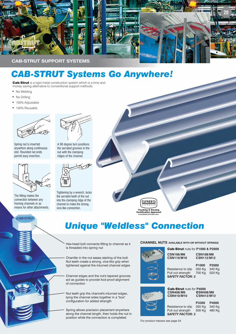
Tightening by a wrench, locks
the serrated teeth of the nut
into the clamping ridge of the
channel to make the strong,
vice-like connection.
Spring nut is inserted
anywhere along continuous
slot. Rounded nut ends
permit easy insertion.
A 90 degree turn positions
the serrated grooves in the
nut with the clamping
ridges of the channel.
The fitting makes the
connection between any
framing channels or as
means for other attachments.
NEW!
41 x 41 UNIFORMLY DISTRIBUTED LOAD
41 x 21 UNIFORMLY DISTRIBUTED LOAD
SAFE LOADS
41 x 41 PLAIN 41 x 41 SLOTTED
SPAN MM KG KG
500 941.6 876.6
1000 470.8 438.3
1500 313.9 292.2
2000 235.4 219.2
2500 188.3 175.3
3000 156.9 146.1
41 x 21 PLAIN 41 x 21 SLOTTED
SPAN MM KG KG
500 346.8 323.0
1000 173.4 161.5
1500 115.6 107.7
2000 86.7 80.8
2500 69.4 64.6
3000 57.8 53.8
19
P1000 P2000
Resistance to slip 350 Kg 340 KgPull out strength 700 Kg 520 KgSAFETY FACTOR: 2
Cab-Strut nuts for P1000 & P2000
CSN106/M6 CSN108/M8
CSN110/M10 CSN112/M12
Cab-Strut nuts for P4000
CSN406/M6 CSN408/M8
CSN410/M10 CSN412/M12
CHANNEL UTSN AVAILABLE WITH OR WITHOUT SPRINGS
P3300 P4000
Resistance to slip 350 Kg 340 KgPull out strength 500 Kg 480 KgSAFETY FACTOR: 2
For product masses see page 54
20
CAB-STRUT SUPPORT SYSTEMS
CAB-STRUT Systems Go Anywhere!
Tightening by a wrench, locks
the serrated teeth of the nut
into the clamping ridge of the
channel to make the strong,
vice-like connection.
Spring nut is inserted
anywhere along continuous
slot. Rounded nut ends
permit easy insertion.
A 90 degree turn positions
the serrated grooves in the
nut with the clamping
ridges of the channel.
The fitting makes the
connection between any
framing channels or as
means for other attachments.
Hex-head bolt connects fitting to channel as it
is threaded into spring nut
Chamfer in the nut eases starting of the bolt.
Nut teeth create a strong, vice-like grip when
tightened against the inturned channel edges
Channel edges and the nut's tapered grooves
act as guides to provide fool-proof alignment
of connection
Nut teeth grip the channel's inturned edges,
tying the channel sides together in a "box"
configuration for added strength
Spring allows precision placement anywhere
along the channel length, then holds the nut in
position while the connection is completed
Unique "Weldless" Connection
P1000 P2000
Resistance to slip 350 Kg 340 KgPull out strength 700 Kg 520 KgSAFETY FACTOR: 2
Cab-Strut nuts for P1000 & P2000
CSN106/M6 CSN108/M8
CSN110/M10 CSN112/M12
Cab-Strut nuts for P4000
CSN406/M6 SN408/M8C
CSN410/M10 CSN412/M12
CHANNEL UTSN AVAILABLE WITH OR WITHOUT SPRINGS
P3300 P4000
Resistance to slip 350 Kg 340 KgPull out strength 500 Kg 480 KgSAFETY FACTOR: 2
Cab-Strut is a rigid metal construction system which is a time andmoney saving alternative to conventional support methods.
� No Welding
� No Drilling
� 100% Adjustable
� 100% Reusable
Trunking & DuctingCertification Approved
IN ACCORDANCE WITH SANS 61084-1
For product masses see page 54
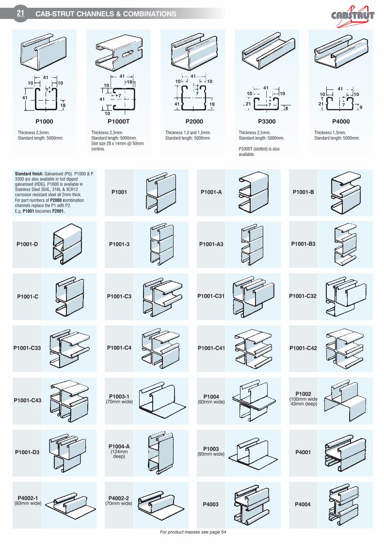
21 CAB-STRUT CHANNELS & COMBINATIONS
Thickness 2,5mm.
Standard length: 5000mm.
P1000 P2000 P3300 P4000P1000T
41
41
10
10
7
18
Thickness 2,5mm.
Standard length: 5000mm.
Slot size 28 x 14mm @ 50mm
centres.
Thickness 1,0 and 1,5mm.
Standard length: 5000mm.
Thickness 2,5mm.
Standard length: 5000mm.
P3300T (slotted) is also
available.
Thickness 1,5mm.
Standard length: 5000mm.
P1001 P1001-A P1001-B
P1001-C
P1001-D P1001-3 P1001-A3
P1001-C32
P1001-C33 P1001-C41 P1001-C42
P1001-C43
P1001-D3
P1002(100mm wide43mm deep)
P1003(93mm wide)
P1003-1(70mm wide)
P1004(93mm wide)
P1004-A(124mmdeep)
P1001-B3
P1001-C31
P4001
P4002-1(93mm wide)
P4002-2(70mm wide) P4003 P4004
Standard finish: Galvanised (PG). P1000 & P
3300 are also available in hot dipped
galvanised (HDG). P1000 is available in
Stainless Steel 304L, 316L & 3CR12
corrosion resistant steel all 2mm thick.
For part numbers of ombinationP2000 c
channels replace the P1 with P2.
E.g. becomesP1001 P2001.
P1001-C3
P1001-C4
41
41
10 10
18
7
41
41
7
19
10 10
41
21
8
10 10
7
41
10 10
219
7
For product masses see page 54
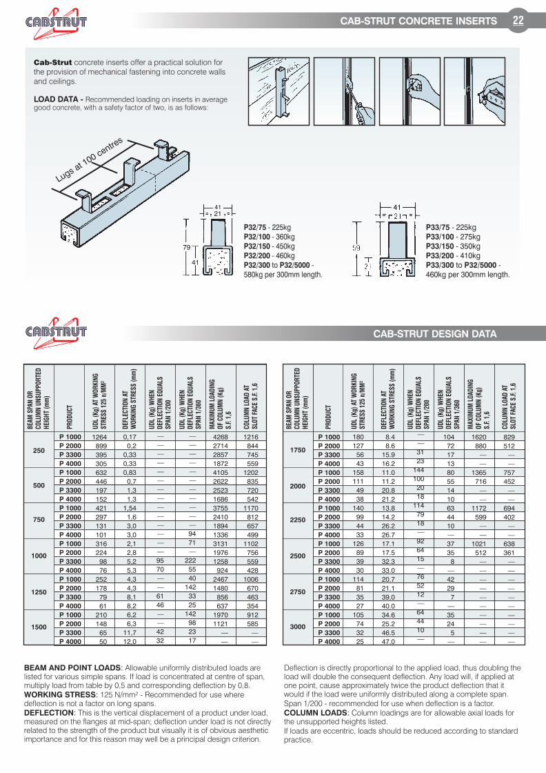
P32/75 - 225kg
- 360kgP32/100
- 450kgP32/150
- 460kgP32/200
to -P32/300 P32/5000
580kg per 300mm length.
P33/75 - 225kg
- 275kgP33/100
- 350kgP33/150
- 410kgP33/200
to -P33/300 P32/5000
460kg per 300mm length.
P 1000
P 2000
P 3300
P 4000
P 1000
P 2000
P 3300
P 4000
P 1000
P 2000
P 3300
P 4000
P 1000
P 2000
P 3300
P 4000
P 1000
P 2000
P 3300
P 4000
P 1000
P 2000
P 3300
P 4000
BEA
M S
PA
N O
R
CO
LU
MN
UN
SU
PP
OR
TED
HEIG
HT (
mm
)
PR
OD
UC
T
UD
L (
Kg)
AT W
OR
KIN
G
STR
ES
S 1
25 n
/MM
²
DEFLEC
TIO
N A
T
WO
RK
ING
STR
ES
S (
mm
)
UD
L (
Kg)
WH
EN
DEFLEC
TIO
N E
QU
ALS
SPA
N 1
/200
UD
L (
Kg)
WH
EN
DEFLEC
TIO
N E
QU
ALS
SPA
N 1
/360
MA
XIM
UM
LO
AD
ING
OF C
OLU
MN
(K
g)
S.F
. 1,6
CO
LU
MN
LO
AD
AT
SLO
T F
AC
E S
.F. 1,6
180
127
56
43
158
111
49
38
140
99
44
33
126
89
39
30
114
81
35
27
105
74
32
25
8.4
8.6
15.9
16.2
11.0
11.2
20.8
21.2
13.8
14.2
26.2
26.7
17.1
17.5
32.3
33.0
20.7
21.1
39,0
40.0
34.6
25.2
46.5
47.0
—
—
31
23
144
100
20
18
114
79
18
—
92
64
15
—
76
52
12
—
64
44
10
—
104
72
17
13
80
55
14
10
63
44
10
—
37
35
8
—
42
29
7
—
35
24
5
—
1620
880
—
—
1365
716
—
—
1172
599
—
—
1021
512
—
—
—
—
—
—
—
—
—
—
829
512
—
—
757
452
—
—
694
402
—
—
638
361
—
—
—
—
—
—
—
—
—
—
1750
2000
2250
2500
2750
3000
P 1000
P 2000
P 3300
P 4000
P 1000
P 2000
P 3300
P 4000
P 1000
P 2000
P 3300
P 4000
P 1000
P 2000
P 3300
P 4000
P 1000
P 2000
P 3300
P 4000
P 1000
P 2000
P 3300
P 4000
1264
899
395
305
632
446
197
152
421
297
131
101
316
224
98
76
252
178
79
61
210
148
65
50
0,17
0,2
0,33
0,33
0,83
0,7
1,3
1,3
1,54
1,6
3,0
3,0
2,1
2,8
5,2
5,3
4,3
4,3
8,1
8,2
6,2
6,3
11,7
12,0
—
—
—
—
—
—
—
—
—
—
—
—
—
—
95
70
—
—
61
46
—
—
42
32
—
—
—
—
—
—
—
—
—
—
—
94
71
—
222
55
40
142
33
25
142
98
23
17
4268
2714
2857
1872
4105
2622
2523
1686
3755
2410
1894
1336
3131
1976
1258
924
2467
1480
856
637
1970
1121
—
—
1216
844
745
559
1202
835
720
542
1170
812
657
499
1102
756
559
428
1006
670
463
354
912
585
—
—
250
500
750
1000
1250
1500
BEA
M S
PA
N O
R
CO
LU
MN
UN
SU
PP
OR
TED
HEIG
HT (
mm
)
PR
OD
UC
T
UD
L (
Kg)
AT W
OR
KIN
G
STR
ES
S 1
25
n/M
M²
DEFLEC
TIO
N A
T
WO
RK
ING
STR
ES
S (
mm
)
UD
L (
Kg)
WH
EN
DEFLEC
TIO
N E
QU
ALS
SP
AN
1/2
00
UD
L (
Kg)
WH
EN
DEFLEC
TIO
N E
QU
ALS
SP
AN
1/3
60
MA
XIM
UM
LO
AD
ING
OF C
OLU
MN
(K
g)
S.F
. 1
,6
CO
LU
MN
LO
AD
AT
SLO
T F
AC
E S
.F.
1,6
Cab-Strut concrete inserts offer a practical solution for
the provision of mechanical fastening into concrete walls
and ceilings.
LOAD DATA - Recommended loading on inserts in averagegood concrete, with a safety factor of two, is as follows:
4121
41
79
41
Lugs at 100 centres
22
CAB-STRUT DESIGN DATA
CAB-STRUT CONCRETE INSERTS
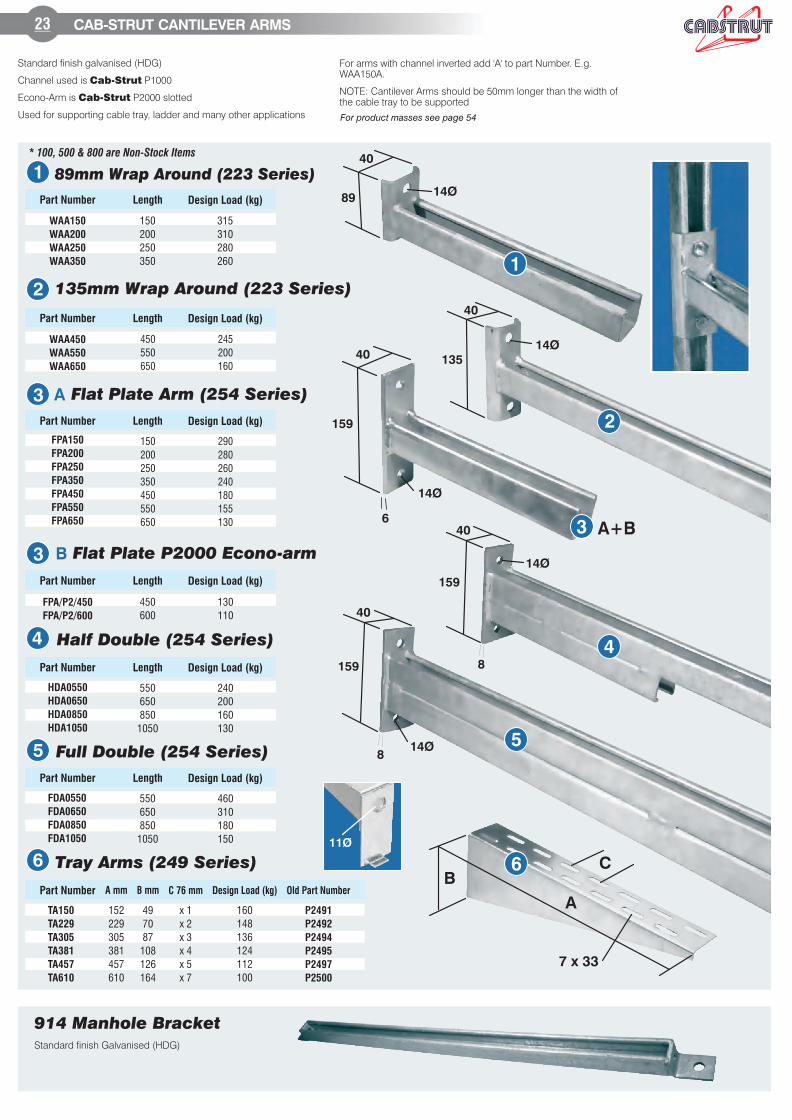
Standard finish galvanised (HDG)
Channel used is P1000Cab-Strut
Econo-Arm is 2P 000 slottedCab-Strut
Used for supporting cable tray, ladder and many other applications
23 CAB- CANTILEVER ARMSSTRUT
89mm Wrap Around (223 Series)
Part Number Length Design Load (kg)
WAA150
WAA200
WAA250
WAA350
150
200
250
350
315
310
280
260
* 100, 500 & 800 are Non-Stock Items
Standard finish Galvanised (HDG)
914 Manhole Bracket
For arms with channel inverted add 'A' to part Number. E.g.WAA150A.
NOTE: Cantilever Arms should be 50mm longer than the width ofthe cable tray to be supported
11Ø
1
89
40
14Ø
14Ø
14Ø
2
135
40
3
159
40
6
14Ø
4
40
159
8
514Ø
159
40
8
6
A
BC
7 x 33
A+B
1
2
3 A
3 B
4
5
6
135mm Wrap Around (223 Series)
Flat Plate Arm (254 Series)
Flat Plate P2000 Econo-arm
Half Double (254 Series)
Full Double (254 Series)
Tray Arms (249 Series)
Part Number Length Design Load (kg)
WAA450
WAA550
WAA650
450
550
650
245
200
160
Part Number Length Design Load (kg)
FPA150
FPA200
FPA250
FPA350
FPA450
FPA550
FPA650
150
200
250
350
450
550
650
290
280
260
240
180
155
130
Part Number Length Design Load (kg)
FPA/P2/450
FPA/P2/600
450
600
130
110
Part Number Length Design Load (kg)
HDA0550
HDA0650
HDA0850
HDA1050
550
650
850
1050
240
200
160
130
Part Number Length Design Load (kg)
FDA0550
FDA0650
FDA0850
FDA1050
550
650
850
1050
460
310
180
150
Part Number
TA150
TA229
TA305
TA381
TA457
TA610
P2491
P2492
P2494
P2495
P2497
P2500
A mm B mm C 76 mm Design Load (kg) Old Part Number
160
148
136
124
112
100
152
229
305
381
457
610
x 1
x 2
x 3
x 4
x 5
x 7
49
70
87
108
126
164
For product masses see page 54
450mmI0005867
550mmI0005868
600mmI0005869
650mmI0005870
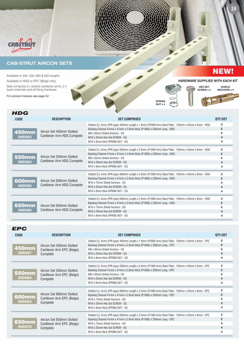
NEW!
CAB-STRUT AIRCON SETS
Available in 450, 550, 600 & 650 lengths
Available in HDG or EPC (Beige only)
Sets comprise 2 x slotted cantilever arms, 2 xback channels and all fixing hardware
Aircon Set 450mm Slotted
Cantilever Arm HDG Complete
Aircon Set 50mm Slotted5
Cantilever HDG CompleteArm
Slotted C/L Arms (FPA type) 50mm Length x mm (P1000 Arm) Back Plate : 150mm x 45mm x 6mm - HDG5 2.0
Backing Channel 41mm x 41mm x 2.0mm thick (P1000) x 250mm Long - HDG
M8 x 65 Shield Anchors - EGmm
M10 x 25mm Hex Set SCREW - EG
M10 x 8mm thick SPRING NUT - EG
2
2
4
4
4
Aircon Set 0mm Slotted60
Cantilever HDG CompleteArm
Slotted C/L Arms (FPA type) 0mm Length x mm (P1000 Arm) Back Plate : 150mm x 45mm x mm - HDG60 2.0 8
Backing Channel 41mm x 41mm x 2.0mm thick (P1000) x 250mm Long - HDG
M x 5 Shield Anchors - EG10 7 mm
M10 x 25mm Hex Set SCREW - EG
M10 x 8mm thick SPRING NUT - EG
Aircon Set 50mm Slotted6
Cantilever HDG CompleteArm
Slotted C/L Arms (FPA type) 50mm Length x 0mm (P 000 Arm) Back Plate : 150mm x 45mm x mm - HDG6 2. 1 8
Backing Channel 41mm x 41mm x 2.0mm thick (P1000) x 250mm Long - HDG
M x 5 Shield Anchors - EG10 7 mm
M10 x 25mm Hex Set SCREW - EG
M10 x 8mm thick SPRING NUT - EG
HDG
Aircon Set 450mm Slotted
Cantilever E ( eige)Arm PC B
Complete
Slotted C/L Arms (FPA type) 450mm Length x 1.6mm (P2000 Arm) Back Plate : 150mm x 45mm x 6mm - EPC
Backing Channel 41mm x 41mm x 2.0mm thick (P1000) x 250mm Long - EPC
M8 x 65 Shield Anchors - EGmm
M10 x 25mm Hex Set SCREW - EG
M10 x 8mm thick SPRING NUT - EG
Aircon Set 50mm Slotted5
Cantilever E ( eige)Arm PC B
Complete
Slotted C/L Arms (FPA type) 50mm Length x mm (P1000 Arm) Back Plate : 150mm x 45mm x 6mm -5 2.0 EPC
Backing Channel 41mm x 41mm x 2.0mm thick (P1000) x 250mm Long - EPC
M8 x 65 Shield Anchors - EGmm
M10 x 25mm Hex Set SCREW - EG
M10 x 8mm thick SPRING NUT - EG
Aircon Set 0mm Slotted60
Cantilever E ( eige)Arm PC B
Complete
Slotted C/L Arms (FPA type) 0mm Length x mm (P1000 Arm) Back Plate : 150mm x 45mm x mm -60 2.0 8 EPC
Backing Channel 41mm x 41mm x 2.0mm thick (P1000) x 250mm Long - EPC
M x 5 Shield Anchors - EG10 7 mm
M10 x 25mm Hex Set SCREW - EG
M10 x 8mm thick SPRING NUT - EG
Aircon Set 50mm Slotted6
Cantilever E ( eige)Arm PC B
Complete
Slotted C/L Arms (FPA type) 50mm Length x 0mm (P 000 Arm) Back Plate : 150mm x 45mm x mm -6 2. 1 8 EPC
Backing Channel 41mm x 41mm x 2.0mm thick (P1000) x 250mm Long - EPC
M x 5 Shield Anchors - EG10 7 mm
M10 x 25mm Hex Set SCREW - EG
M10 x 8mm thick SPRING NUT - EG
450mm
24
CODE DESCRIPTION SET COMPRISES QTY/SET
Slotted C/L Arms (FPA type) 450mm Length x 1.6mm (P2000 Arm) Back Plate : 150mm x 45mm x 6mm - HDG
Backing Channel 41mm x 41mm x 2.0mm thick (P1000) x 250mm Long - HDG
M8 x 65 Shield Anchors - EGmm
M10 x 25mm Hex Set SCREW - EG
M10 x 8mm thick SPRING NUT - EG
2
2
4
4
4
I0005863
550mmI0005864
600mmI0005865
650mmI0005866
CODE DESCRIPTION SET COMPRISES QTY/SET
2
2
4
4
4
EPC
HARDWARE SUPPLIED WITH EACH KIT
SPRING
NUT x 4
HEX SET
SCREW x 4
SHIELD
ANCHORS x 4
2
2
4
4
4
2
2
4
4
4
2
2
4
4
4
2
2
4
4
4
2
2
4
4
4
For product masses see page 54
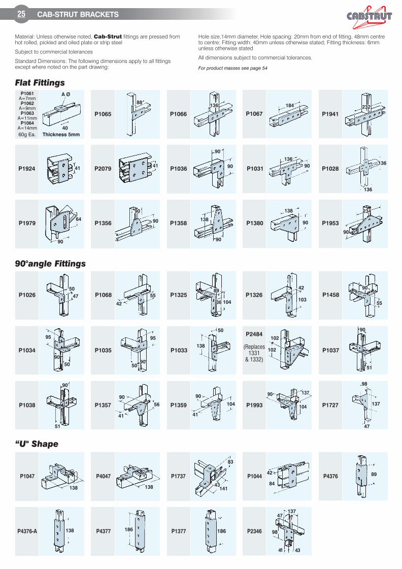
Flat Fittings
8888136136 184 232232
A Ø
40
4141
90
90
136
90
136
136
41
9090
90 138
90
138
90
90
234234
90
64
90°angle Fittings
42
55
89
3636 104
42
103
90
55
50
47
509090
95
138
50
102
102
90
51
95
9090
50
41
90
56
41
90
104
90 137
104
98
47
137
90
51
1384343
141
83
42
84
89
138
186 186
13747
98
4341
138
“ " ShapeU
P1065
P1924
P1068
P1035P1034 P1033
P2484
(Replaces
1331
& 1332)
P1037
P1026 P1325 P1326 P1458
P1979 P1358 P1380 P1953
P1028
60g Ea.
P1066 P1067 P1941
P1061
A=7mmP1062
A=9mmP1063
A=11mmP1064
A=14mm
P1727P1993P1359P1357P1038
P2079 P1036 P1031
P1356
P1047 P4376
P4376-A
P4047
P4377
P1737
P1377
P1044
P2346
Thickness 5mm
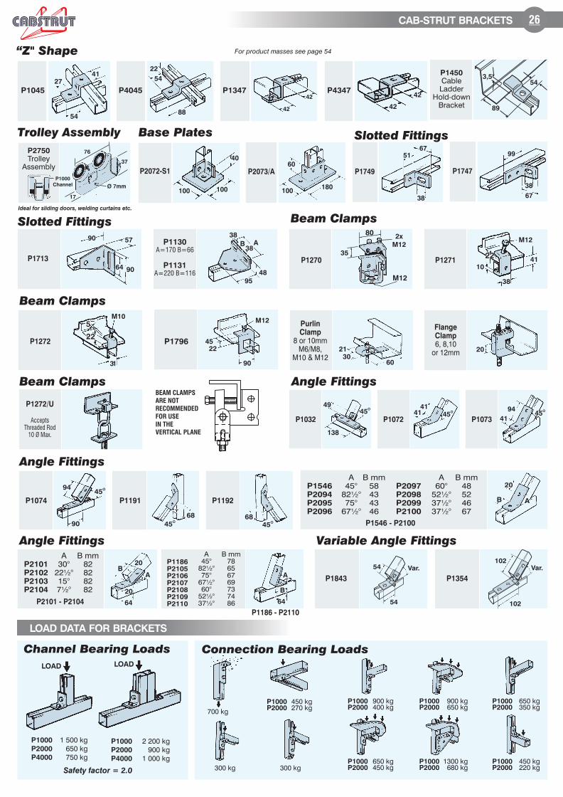
25 CAB-STRUT BRACKETS
Material: Unless otherwise noted, fittings are pressed fromCab-Strut
hot rolled, pickled and oiled plate or strip steel
Subject to commercial tolerances
Standard Dimensions: The following dimensions apply to all fittingsexcept where noted on the part drawing:
Hole size,14mm diameter, Hole spacing: 20mm from end of fitting, 48mm centreto centre: Fitting width: 40mm unless otherwise stated; Fitting thickness: 6mmunless otherwise stated
All dimensions subject to commercial tolerances.
For product masses see page 54
27
41
54
22
54
88
42
42
“ " ShapeZ
42
42
51
67
38
38
67
99
57
64 90
90
Slotted Fittings
95
48
A3838
B
38
M10
31
2222
55
45
22
90
M12
Beam Clamps
21
3060
20
35
M12
80
45O
4141
41
9445
O
45O94
90 45O
68
49
45O
138
AB
20
B
A
6464
20
BA
20
Angle Fittings
45O
68
P1045 P4045 P1347 P4347
P2101 - P2104
P2101
P2102
P2103
P2104
A30°
22½°15°7½°
B mm82828282
P1546 - P2100
P1546
P2094
P2095
P2096
P2097
P2098
P2099
P2100
A45°
82½°75°
67½°
A60°
52½°37½°37½°
B mm58434346
B mm48524667
P1186 - P2110
P1186
P2105
P2106
P2107
P2108
P2109
P2110
A45°
82½°75°
67½°60°
52½°37½°
B mm78656769737486
P1272
Purlin
Clamp
8 or 10mmM6/M8,
M10 & M12
P1272/U
Accepts
Threaded Rod
10 Ø Max.
Base Plates
40
100100
P2072-S1
180100
60
P2073/A P1749 P1747
P1713
Flange
Clamp
6, 8,10or 12mm
P1032 P1072
P1074 P1191 P1192
P1073
P1796
Connection Bearing Loads
900 kg400 kg
P1000P2000
650 kg450 kg
P1000P2000
900 kg650 kg
P1000P2000
1300 kg680 kg
P1000P2000
650 kg350 kg
P1000P2000
450 kg220 kg
P1000P2000
450 kg270 kg
P1000P2000
P1130
A=170 B=66
P1131
A=220 B=116
P1270
Channel Bearing Loads
Safety factor = 2.0
P1000
P2000
P4000
1 500 kg
650 kg
750 kg
LOAD
P1000
P2000
P4000
2 200 kg
900 kg
1 000 kg
LOAD
300 kg 300 kg
700 kg
M12
41
38
2222
10P1271
2x
M12
26CAB-STRUT BRACKETS
LOAD DATA FOR BRACKETS
BEAM CLAMPS
ARE NOT
RECOMMENDED
FOR USE
IN THE
VERTICAL PLANE
Trolley Assembly
89
543,5
P1450
CableLadder
Hold-downBracket
P2750
TrolleyAssembly
Ideal for sliding doors, welding curtains etc.
P1000
Channel Ø 7mm
37
17
76
For product masses see page 54
Slotted Fittings
Beam Clamps
Angle FittingsBeam Clamps
Angle Fittings
102
102
Var.
54
Var.54
P1843
Variable Angle Fittings
P1354
T
C ( Combi-nut)M8/M10
B
A
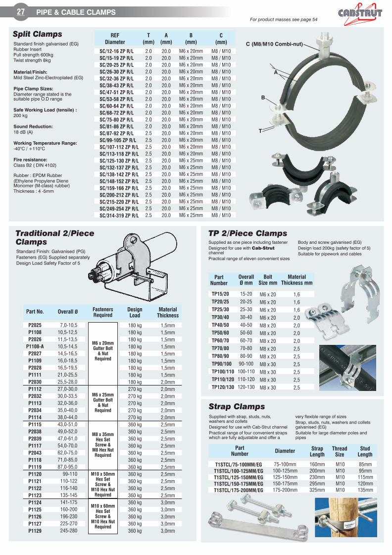
27 PIPE & CABLE CLAMPS
Split ClampsStandard finish galvanised (EG)Rubber InsertPull strength 600kgTwist strength 8kg
Material/Finish:
Mild Steel Zinc-Electroplated (EG)
Pipe Clamp Sizes:
Diameter range stated is thesuitable pipe O.D range
Safe Working Load (tensile) :
200 kg
Sound Reduction:
18 dB (A)
Working Temperature Range:
-40°C / +110°C
Fire resistance:
Class B2 ( DIN 4102)
Rubber : EPDM Rubber
(Ethylene Propylene DieneMonomer (M-class) rubber)
Thickness : 4 -5mm
REF
Diameter
T
(mm)
A
(mm)
B
(mm)
C
(mm)
SC/12-16 ZP R/L
SC/15-19 ZP R/L
SC/20-25 ZP R/L
SC/26-30 ZP R/L
SC/32-36 ZP R/L
SC/38-43 ZP R/L
SC/47-51 ZP R/L
SC/53-58 ZP R/L
SC/60-64 ZP R/L
SC/68-72 ZP R/L
SC/75-80 ZP R/L
SC/81-86 ZP R/L
SC/87-92 ZP R/L
SC/99-105 ZP R/L
SC/107-112 ZP R/L
SC/113-118 ZP R/L
SC/125-130 ZP R/L
SC/132-137 ZP R/L
SC/138-142 ZP R/L
SC/148-152 ZP R/L
SC/159-166 ZP R/L
SC/200-212 ZP R/L
SC/215-220 ZP R/L
SC/249-254 ZP R/L
SC/314-319 ZP R/L
20.0
20.0
20.0
20.0
20.0
20.0
20.0
20.0
20.0
20.0
20.0
20.0
20.0
20.0
20.0
20.0
20.0
20.0
20.0
20.0
20.0
20.0
20.0
20.0
20.0
2.0
2.0
2.0
2.0
2.0
2.0
2.0
2.0
2.0
2.0
2.0
2.0
2.5
2.5
2.5
2.5
2.5
2.5
2.5
2.5
2.5
2.5
2.5
2.5
2.5
M8 / M10
M8 / M10
M8 / M10
M8 / M10
M8 / M10
M8 / M10
M8 / M10
M8 / M10
M8 / M10
M8 / M10
M8 / M10
M8 / M10
M8 / M10
M8 / M10
M8 / M10
M8 / M10
M8 / M10
M8 / M10
M8 / M10
M8 / M10
M8 / M10
M8 / M10
M8 / M10
M8 / M10
M8 / M10
M6 x 20mm
M6 x 20mm
M6 x 20mm
M6 x 20mm
M6 x 20mm
M6 x 20mm
M6 x 20mm
M6 x 20mm
M6 x 20mm
M6 x 20mm
M6 x 20mm
M6 x 20mm
M6 x 20mm
M6 x 20mm
M6 x 20mm
M6 x 20mm
M6 x 25mm
M6 x 25mm
M6 x 25mm
M6 x 25mm
M6 x 25mm
M6 x 25mm
M6 x 25mm
M6 x 25mm
M6 x 25mm
For product masses see page 54
Supplied as one piece including fastener
Designed for use with Cab-Strut
channel
Practical range of eleven convenient sizes
Body and screw galvanised (EG)
Design load 200kg (safety factor of 5)
Suitable for pipework and cables
TP 2/Piece Clamps
TP15/20
TP20/25
TP25/30
TP30/40
TP40/50
TP50/60
TP60/70
TP70/80
TP80/90
TP90/100
TP100/110
TP110/120
TP120/130
15-20
20-25
25-30
30-40
40-50
50-60
60-70
70-80
80-90
90-100
100-110
110-120
120-130
Part
Number
Overall
mmØ
Bolt
Size mm
Material
Thickness mm
M6 x 20
M6 x 20
M6 x 20
M6 x 20
M8 x 20
M8 x 20
M8 x 20
M8 x 20
M8 x 20
M8 x 30
M8 x 30
M8 x 30
M8 x 30
1,6
1,6
1,6
2,0
2,0
2,0
2,0
2,5
2,5
2,5
2,5
2,5
2,5
Strap ClampsSupplied with strap, studs, nuts,washers and collets
Designed for use with channelCab-Strut
Practical range of four convenient strapswhich are fully adjustable and offer a
very flexible range of sizes
Strap, studs, nuts, washers and colletsgalvanised (EG)
Suitable for large diameter poles andpipes
Part
NumberDiameter
Strap
Length
Thread
Size
Stud
Length
T1STCL/ MM/EG75-100
T1STCL/100-125MM/EG
T1STCL/125-150MM/EG
T1STCL/150-175MM/EG
T1STCL/175-200MM/EG
75-100mm
100-125mm
125-150mm
150-175mm
175-200mm
160mm
200mm
230mm
295mm
325mm
M10
M10
M10
M10
M10
85mm
95mm
115mm
120mm
135mm
Standard Finish: Galvanised (PG)
Fasteners (EG) Supplied separately
Design Load Safety Factor of 5
Traditional 2/PieceClamps
Part No. Overall ØDesign
Load
180 kg
180 kg
180 kg
180 kg
180 kg
180 kg
180 kg
180 kg
180 kg
270 kg
270 kg
270 kg
270 kg
270 kg
360 kg
360 kg
360 kg
360 kg
360 kg
360 kg
360 kg
360 kg
360 kg
360 kg
360 kg
360 kg
360 kg
360 kg
360 kg
360 kg
P2025
P1108
P2026
P1108-A
P2027
P1109
P2028
P1111
P2030
P1112
P2032
P1113
P2034
P1114
P1115
P2038
P2039
P1117
P2043
P1118
P1119
P1120
P1121
P1122
P1123
P1124
P1125
P1126
P1127
P1129
Material
Thickness
Fasteners
Required
1,5mm
1,5mm
1,5mm
1,5mm
1,5mm
1,5mm
1,5mm
1,5mm
2,0mm
2,0mm
2,0mm
2,0mm
2,0mm
2,0mm
2,5mm
2,5mm
2,5mm
2,5mm
2,5mm
2,5mm
2,5mm
2,5mm
2,5mm
2,5mm
2,5mm
3,0mm
3,0mm
3,0mm
3,0mm
3,0mm
7,0-10,5
10,5-12,5
11,5-13,5
10,5-14,5
14,5-16,5
16,0-18,5
16,5-19,5
21,0-25,5
25,5-28,0
27,0-30,0
30,0-33,5
32,0-36,0
35,0-40,0
38,0-44,0
43,0-51,0
49,0-52,0
47,0-61,0
54,0-70,0
62,0-75,0
71,0-85,0
87,0-95,0
99-110
110-122
116-140
135-145
141-175
160-200
196-230
225-270
245-280
M6 x 20mm
Gutter Bolt
& Nut
Required
M6 x 25mm
Gutter Bolt
& Nut
Required
M8 x 35mm
Hex Set
Screw &
M8 Hex Nut
Required
M10 x 50mm
Hex Set
Screw &
M10 Hex Nut
Required
M10 x 60mm
Hex Set
Screw &
M10 Hex Nut
Required
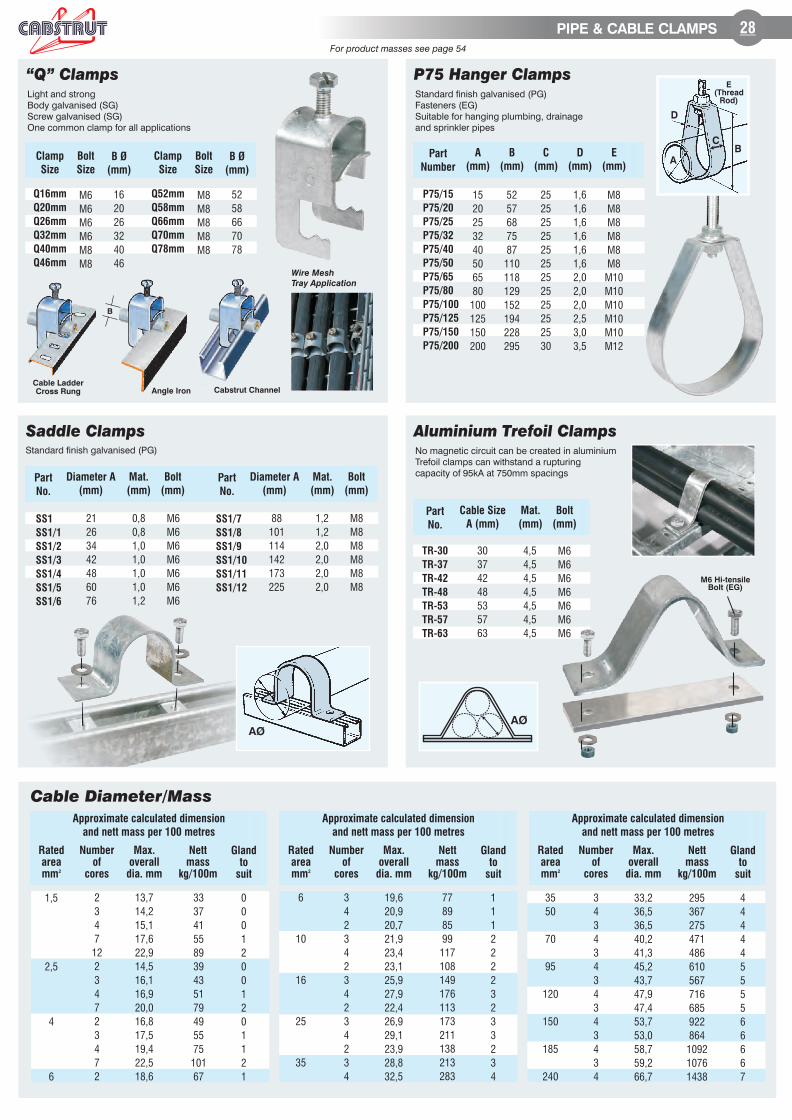
28PIPE & CABLE CLAMPS
“Q” ClampsLight and strong
Body galvanised (SG)
Screw galvanised (SG)
One common clamp for all applications
Clamp
Size
M6
M6
M6
M6
M8
M8
Q16mm
Q20mm
Q26mm
Q32mm
Q40mm
Q46mm
Bolt
Size
B Ø
(mm)
16
20
26
32
40
46
Clamp
Size
M8
M8
M8
M8
M8
Q52mm
Q58mm
Q66mm
Q70mm
Q78mm
Bolt
Size
B Ø
(mm)
52
58
66
70
78
P75 Hanger ClampsStandard finish galvanised (PG)
Fasteners (EG)
Suitable for hanging plumbing, drainage
and sprinkler pipes
Part
Number
A
(mm)
B
(mm)
C
(mm)
D
(mm)
E
(mm)
15
20
25
32
40
50
65
80
100
125
150
200
P75/15
P75/20
P75/25
P75/32
P75/40
P75/50
P75/65
P75/80
P75/100
P75/125
P75/150
P75/200
52
57
68
75
87
110
118
129
152
194
228
295
25
25
25
25
25
25
25
25
25
25
25
30
1,6
1,6
1,6
1,6
1,6
1,6
2,0
2,0
2,0
2,5
3,0
3,5
M8
M8
M8
M8
M8
M8
M10
M10
M10
M10
M10
M12
E
(Thread
Rod)
A
B
D
C
Saddle ClampsStandard finish galvanised (PG)
Aluminium Trefoil ClampsNo magnetic circuit can be created in aluminium
Trefoil clamps can withstand a rupturing
capacity of 95kA at 750mm spacings
Cable Diameter/ assM
Part
No.
Diameter A
(mm)
Mat.
(mm)
Bolt
(mm)
SS1
SS1/1
SS1/2
SS1/3
SS1/4
SS1/5
SS1/6
0,8
0,8
1,0
1,0
1,0
1,0
1,2
21
26
34
42
48
60
76
M6
M6
M6
M6
M6
M6
M6
SS1/7
SS1/8
SS1/9
SS1/10
SS1/11
SS1/12
1,2
1,2
2,0
2,0
2,0
2,0
88
101
114
142
173
225
M8
M8
M8
M8
M8
M8
Part
No.
Diameter A
(mm)
Mat.
(mm)
Bolt
(mm)
AØ
Part
No.
Cable Size
A (mm)
Mat.
(mm)
Bolt
(mm)
TR-30
TR-37
TR-42
TR-48
TR-53
TR-57
TR-63
4,5
4,5
4,5
4,5
4,5
4,5
4,5
30
37
42
48
53
57
63
M6
M6
M6
M6
M6
M6
M6
M6 Hi-tensile
Bolt (EG)
AØ
Rated
area
mm2
Number
of
cores
Approximate calculated dimension
and nett mass per 100 metres
Max.
overall
dia. mm
Nett
mass
kg/100m
Gland
to
suit
2
3
4
7
12
2
3
4
7
2
3
4
7
2
13,7
14,2
15,1
17,6
22,9
14,5
16,1
16,9
20,0
16,8
17,5
19,4
22,5
18,6
33
37
41
55
89
39
43
51
79
49
55
75
101
67
0
0
0
1
2
0
0
1
2
0
1
1
2
1
1,5
2,5
4
6
Cable Ladder
Cross Rung
B
Wire Mesh
Tray Application
Angle Iron Cabstrut Channel
6
10
16
25
35
3
4
2
3
4
2
3
4
2
3
4
2
3
4
19,6
20,9
20,7
21,9
23,4
23,1
25,9
27,9
22,4
26,9
29,1
23,9
28,8
32,5
77
89
85
99
117
108
149
176
113
173
211
138
213
283
1
1
1
2
2
2
2
3
2
3
3
2
3
4
35
50
70
95
120
150
185
240
3
4
3
4
3
4
3
4
3
4
3
4
3
4
33,2
36,5
36,5
40,2
41,3
45,2
43,7
47,9
47,4
53,7
53,0
58,7
59,2
66,7
295
367
275
471
486
610
567
716
685
922
864
1092
1076
1438
4
4
4
4
4
5
5
5
5
6
6
6
6
7
Rated
area
mm2
Number
of
cores
Approximate calculated dimension
and nett mass per 100 metres
Max.
overall
dia. mm
Nett
mass
kg/100m
Gland
to
suit
Rated
area
mm2
Number
of
cores
Approximate calculated dimension
and nett mass per 100 metres
Max.
overall
dia. mm
Nett
mass
kg/100m
Gland
to
suit
For product masses see page 54


![Wall SyStemS Custom Metal Walls - Acoustech Supplyacoustechsupply.com/pdf/datapages/MetalWalls.pdfRg 2504 Hole Size:Hole Size: 2.5mm [.098”] 2.5mm [.098”] % Open Area: % Open Area:](https://img.pdfslide.net/doc/110x75/5fc79e967ff37248f7459248/wall-systems-custom-metal-walls-acoustech-s-rg-2504-hole-sizehole-size-25mm.jpg)