Embed Size (px)
Citation preview
29.7.2004 Fracture Mechanics of solid rocket propellants
1
Fracture Mechanics – Presentation of the course report
The application of fracture mechanics to the structural assessment of solid propellant rocket motors
Giuseppe Tussiwand
SP Lab, Politecnico di Milano (aerospace, energetics)

29.7.2004 Fracture Mechanics of solid rocket propellants
2
Presentation outline
Introduction on Solid Rocket Technology, Effect of a crack in a motor
Material properties
Manufacturing problems
Literature Survey
Crack Deterioration Experiments
Subcritical Propagation, Fatigue and Service Life
Toughness Testing and unstable propagation limits

29.7.2004 Fracture Mechanics of solid rocket propellants
3
Solid Propellant Technology
Applications:
Mining
Solid Rocket Motors
Airbags
Gun propellant
Rescue Systems

29.7.2004 Fracture Mechanics of solid rocket propellants
4
Solid Rocket Motor Operation
motornozzlecombustion t
mmm∂∂=−
nb
solid aprdt
dx ==:
dtbb cAprA ⋅⋅=⋅⋅ρρ⋅⋅= bbcombustion Arm
dtnozzle cApm ⋅⋅=
pAcT tF ⋅⋅=
n
t
b
d AA
cap −
⎟⎟⎠
⎞⎜⎜⎝
⎛ ⋅= 11
ρ
casegrain
nozzleportigniter
29.7.2004 Fracture Mechanics of solid rocket propellants
5
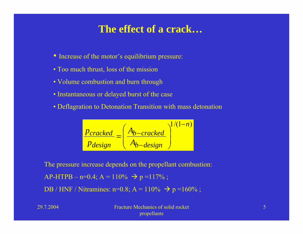
The effect of a crack…
)1/(1 n
designb
crackedb
design
crackedA
Ap
p−
−
−⎟⎟⎠
⎞⎜⎜⎝
⎛=
• Increase of the motor’s equilibrium pressure:
• Too much thrust, loss of the mission
• Volume combustion and burn through
• Instantaneous or delayed burst of the case
• Deflagration to Detonation Transition with mass detonation
The pressure increase depends on the propellant combustion:
AP-HTPB – n=0.4; A = 110% p =117% ;
DB / HNF / Nitramines: n=0.8; A = 110% p =160% ;
29.7.2004 Fracture Mechanics of solid rocket propellants
6
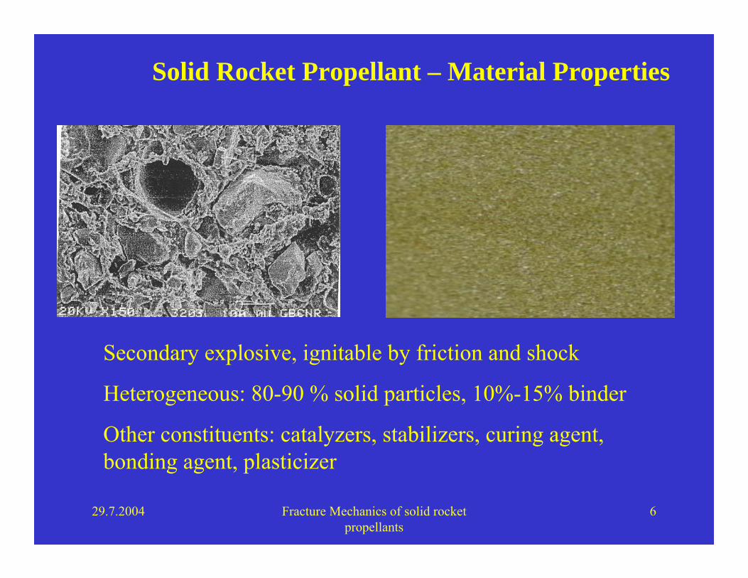
Solid Rocket Propellant – Material Properties
Secondary explosive, ignitable by friction and shock
Heterogeneous: 80-90 % solid particles, 10%-15% binder
Other constituents: catalyzers, stabilizers, curing agent, bonding agent, plasticizer
29.7.2004 Fracture Mechanics of solid rocket propellants
7
Solid Rocket Propellant – Material Properties
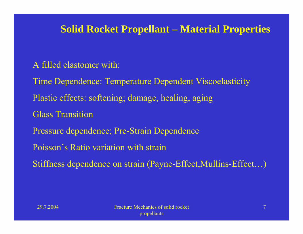
A filled elastomer with:
Time Dependence: Temperature Dependent Viscoelasticity
Plastic effects: softening; damage, healing, aging
Glass Transition
Pressure dependence; Pre-Strain Dependence
Poisson’s Ratio variation with strain
Stiffness dependence on strain (Payne-Effect,Mullins-Effect…)
29.7.2004 Fracture Mechanics of solid rocket propellants
8
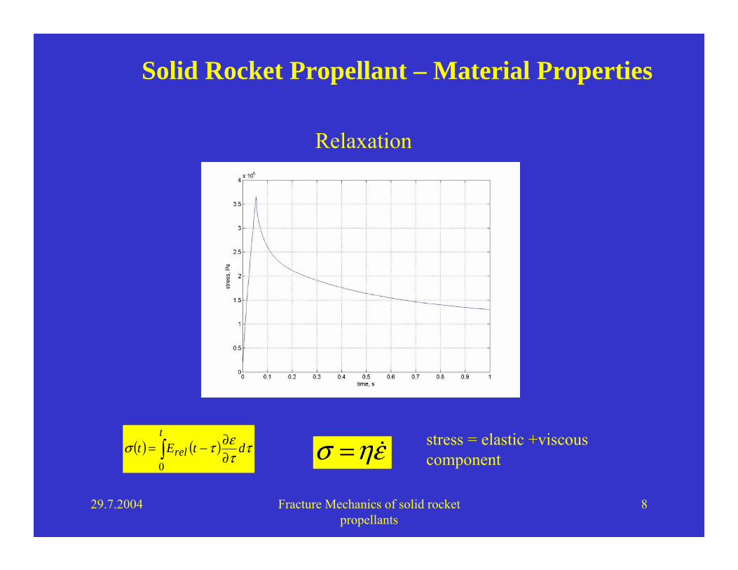
Solid Rocket Propellant – Material Properties
( ) ( ) ττετσ dtEt
t
rel ∂∂−= ∫
0
Relaxation
εησ = stress = elastic +viscous component

29.7.2004 Fracture Mechanics of solid rocket propellants
9
Tref
T1 < Tref
Log time
E(t)
log(aT) for T1 vs.Tref
Solid Rocket Propellant – Material Properties
Tatt =*
Definition of a material time
29.7.2004 Fracture Mechanics of solid rocket propellants
10
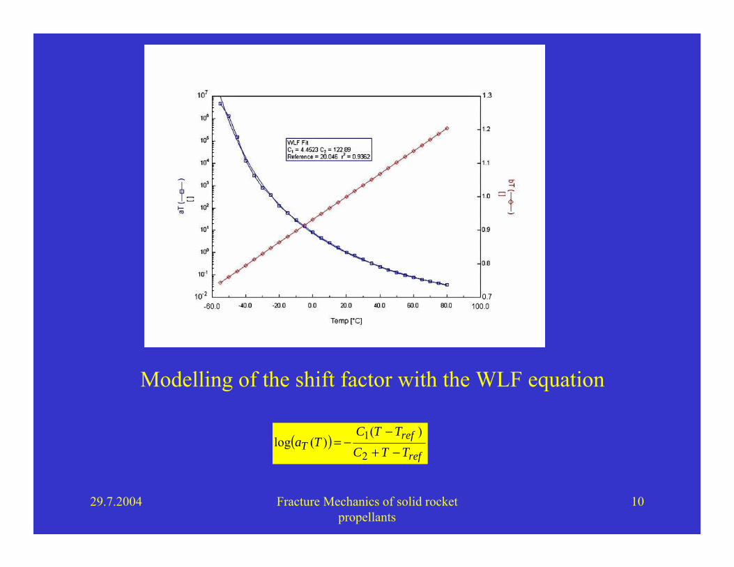
Modelling of the shift factor with the WLF equation
( )ref
refT TTC
TTCTa
−+−
−=2
1 )()(log
29.7.2004 Fracture Mechanics of solid rocket propellants
11
Solid Rocket Propellant – Material Properties
Failure by:
• Disentanglement
• Chain scission
• Shear yielding
• Crazing
• Dewetting
29.7.2004 Fracture Mechanics of solid rocket propellants
12
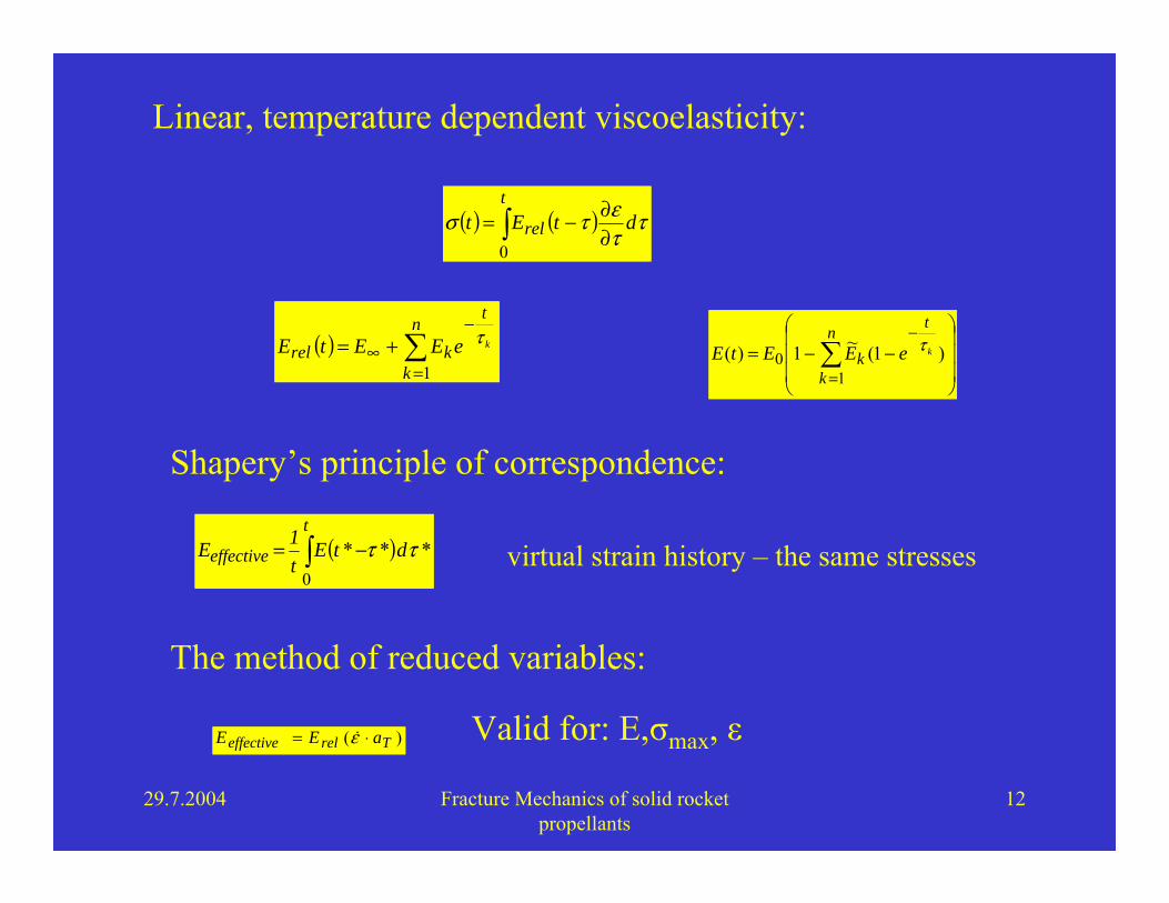
( ) ∑=
−∞ +=
n
k
t
krel keEEtE1
τ
Linear, temperature dependent viscoelasticity:
( ) ( ) ττετσ dtEt
t
rel ∂∂−= ∫
0
Shapery’s principle of correspondence:
⎟⎟⎟
⎠
⎞
⎜⎜⎜
⎝
⎛−−= ∑
=
−n
k
t
k keEEtE1
0 )1(~1)( τ
( )∫ −=t
effective dtEt1 E
0*** ττ virtual strain history – the same stresses
)( Treleffective aE E ⋅= ε
The method of reduced variables:
Valid for: E,σmax, ε

29.7.2004 Fracture Mechanics of solid rocket propellants
13
Load cases for a motor
Thermal Cycling due to different CTE for case and propellant (high strains in the bore – low-medium number of cycles)
Vibrations (Transport,Handling, Captive Carriage…-moderate stresses, but a lot of cycles)
Ignition pressurization (very high stresses, low strains, just once)
If there is a crack, even microscopic…
how fast does it propagate with cycling? (subcritical propagation)
How big can it be ? (ballistics,critical propagation,structural-ballistic coupling)

29.7.2004 Fracture Mechanics of solid rocket propellants
14
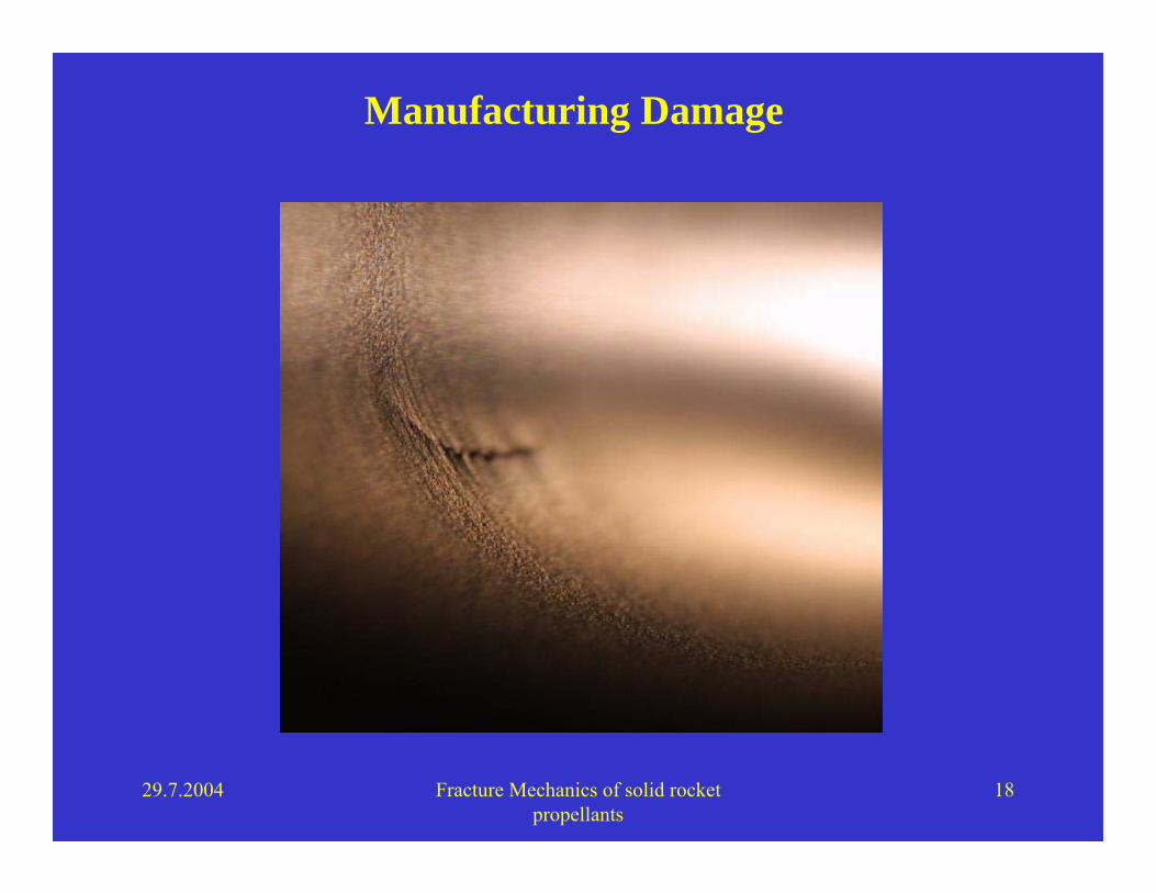
Manufacturing Flaws
• Mixing of the ingredients
• Casting (different methods)
• Curing at 60+ °C
• Cooling
• Extraction of the mandrel …troubles!

29.7.2004 Fracture Mechanics of solid rocket propellants
15
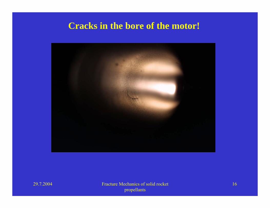
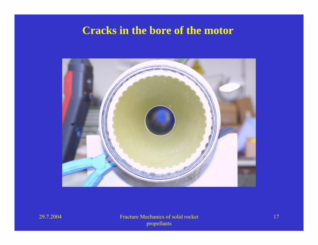
Manufacturing Flaws
The extraction might cause microcracks at the bore: significant service life reduction;
29.7.2004 Fracture Mechanics of solid rocket propellants
16
Cracks in the bore of the motor!
29.7.2004 Fracture Mechanics of solid rocket propellants
17
Cracks in the bore of the motor
29.7.2004 Fracture Mechanics of solid rocket propellants
18
Manufacturing Damage

29.7.2004 Fracture Mechanics of solid rocket propellants
19
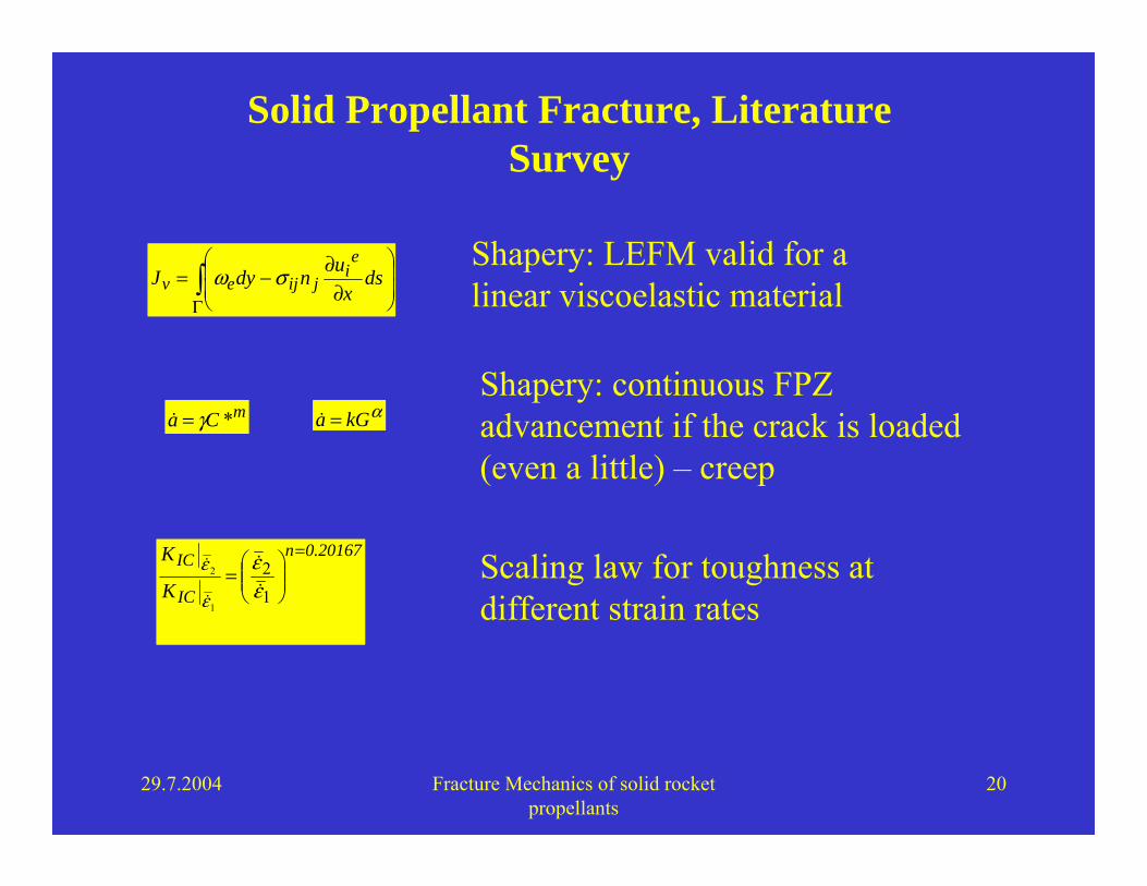
Solid Propellant Fracture, Literature Survey
Essentially: course material, Anderson, viscoelastic fracture, exact solutions.
Application and development of the work of Shapery & students allowed many predictions:
- qualitative and quantitative predictions on the P-E parameters, the toughness, the general behaviour
- scaling rules
- revision of the ASTM standard for toughness
These predictions were checked experimentally
29.7.2004 Fracture Mechanics of solid rocket propellants
20
Solid Propellant Fracture, Literature Survey
∫Γ
⎟⎟⎠
⎞⎜⎜⎝
⎛
∂∂−= ds
xundyJ
ei
jijev σω
αGka =
0.20167n
IC
IC
K
K =
⎟⎟⎠
⎞⎜⎜⎝
⎛=
1
2
1
2
εε
ε
ε
mCa *γ=
Shapery: LEFM valid for a linear viscoelastic material
Shapery: continuous FPZ advancement if the crack is loaded (even a little) – creep
Scaling law for toughness at different strain rates

29.7.2004 Fracture Mechanics of solid rocket propellants
21
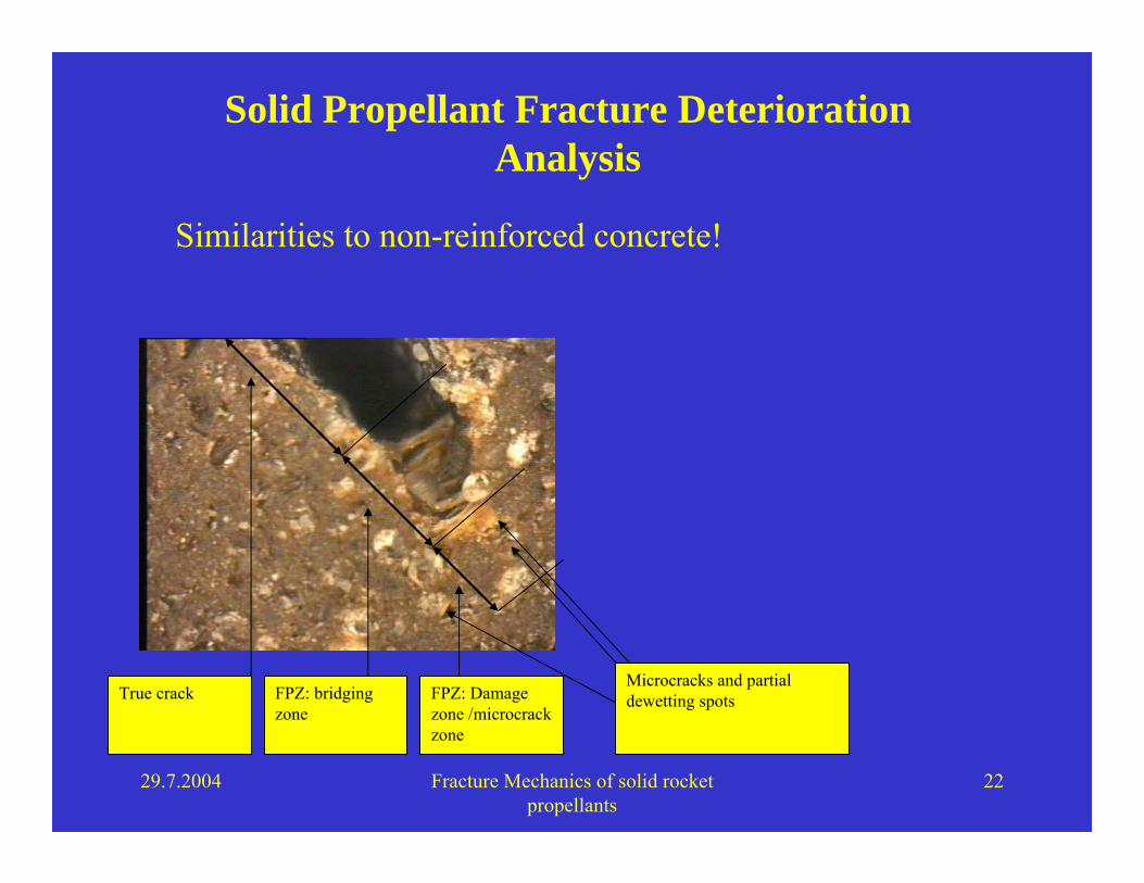
Solid Propellant Fracture Deterioration Analysis
29.7.2004 Fracture Mechanics of solid rocket propellants
22
Solid Propellant Fracture Deterioration Analysis
Microcracks and partialdewetting spotsFPZ: Damage
zone /microcrack zone
FPZ: bridging zone
True crack
Similarities to non-reinforced concrete!
29.7.2004 Fracture Mechanics of solid rocket propellants
23
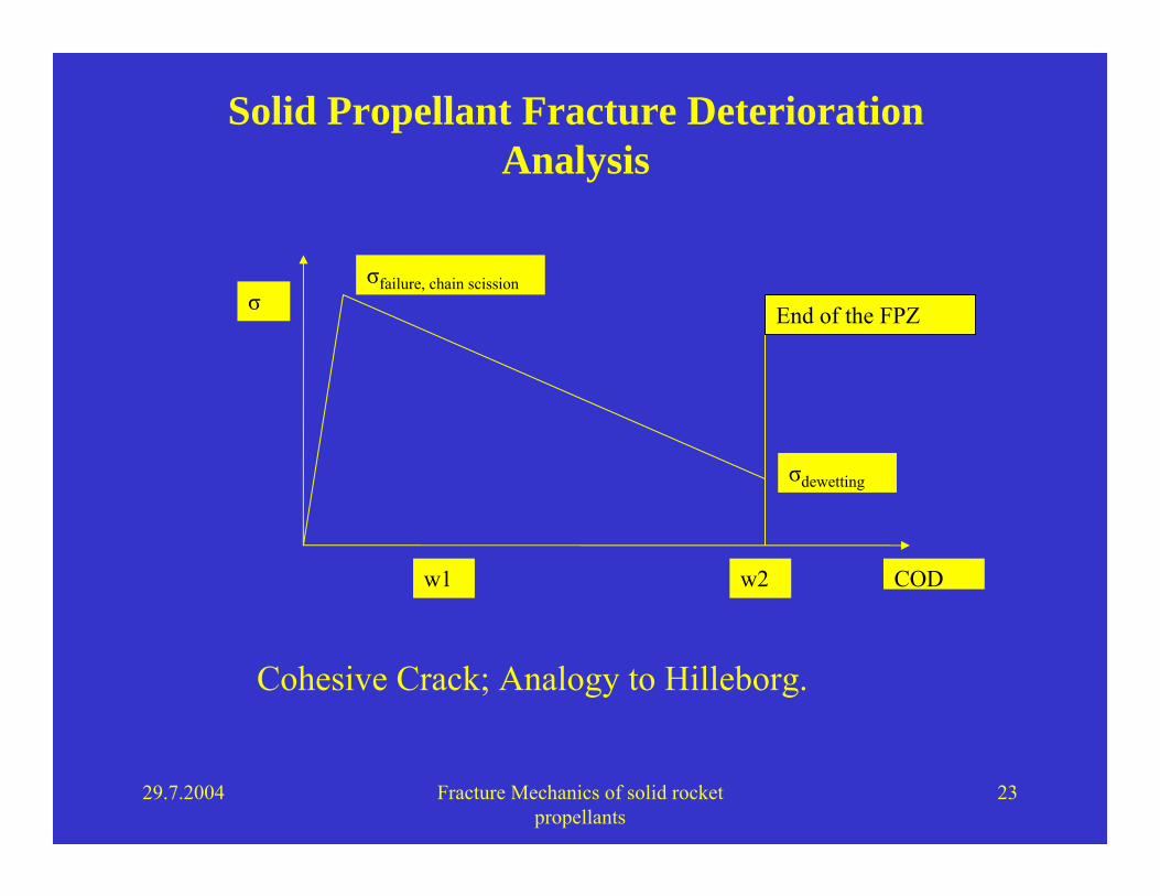
Solid Propellant Fracture Deterioration Analysis
End of the FPZ
σfailure, chain scission
σdewetting
σ
w1 w2 COD
Cohesive Crack; Analogy to Hilleborg.
29.7.2004 Fracture Mechanics of solid rocket propellants
24
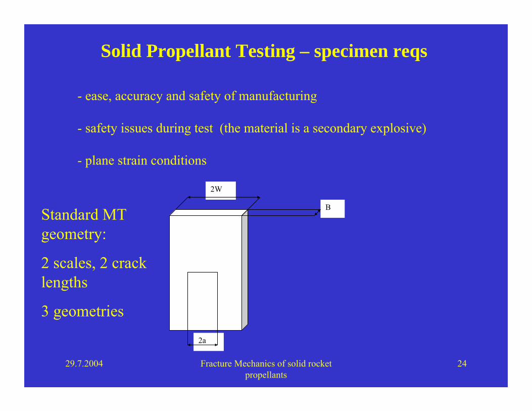
Solid Propellant Testing – specimen reqs
- ease, accuracy and safety of manufacturing
- safety issues during test (the material is a secondary explosive)
- plane strain conditions
2a
B
2W
Standard MT geometry:
2 scales, 2 crack lengths
3 geometries
29.7.2004 Fracture Mechanics of solid rocket propellants
25
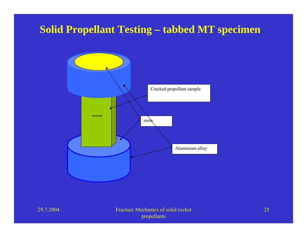
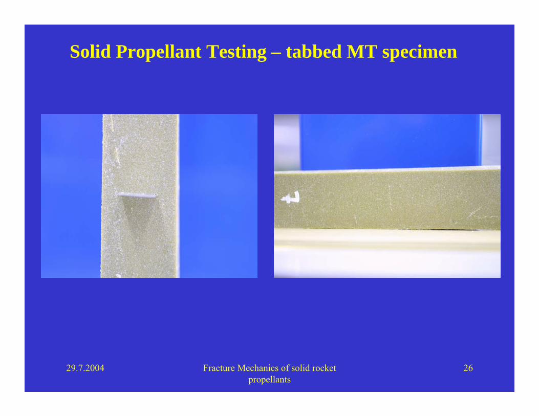
Solid Propellant Testing – tabbed MT specimen
resin
Aluminium alloy
Cracked propellant sample
29.7.2004 Fracture Mechanics of solid rocket propellants
26
Solid Propellant Testing – tabbed MT specimen
29.7.2004 Fracture Mechanics of solid rocket propellants
27
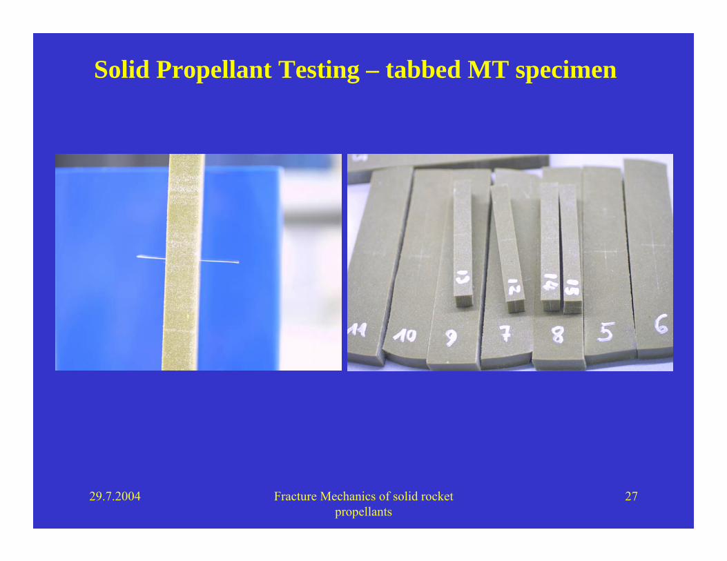
Solid Propellant Testing – tabbed MT specimen
29.7.2004 Fracture Mechanics of solid rocket propellants
28
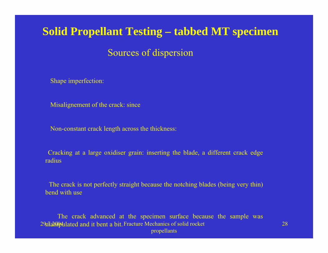
Solid Propellant Testing – tabbed MT specimen
Shape imperfection:
Misalignement of the crack: since
Non-constant crack length across the thickness:
Cracking at a large oxidiser grain: inserting the blade, a different crack edge radius
The crack is not perfectly straight because the notching blades (being very thin) bend with use
The crack advanced at the specimen surface because the sample was manipulated and it bent a bit.
Sources of dispersion

29.7.2004 Fracture Mechanics of solid rocket propellants
29
Solid Propellant Testing, Fatigue test procedure
• Digital measurement of the crack length before testing under an optical microscope
• Insertion of the sample in the machine and application of a very small pre-load (0.5 N) to make sure the specimen was rigidly fixed in the grips.
• Cycling between a maximum and a minimum load previously chosen, at a frequency of about 0.4-0.5 Hz.
• Extraction of the sample after the application of the cycles, and digital crack length measurement with the same optical microscope.

29.7.2004 Fracture Mechanics of solid rocket propellants
30
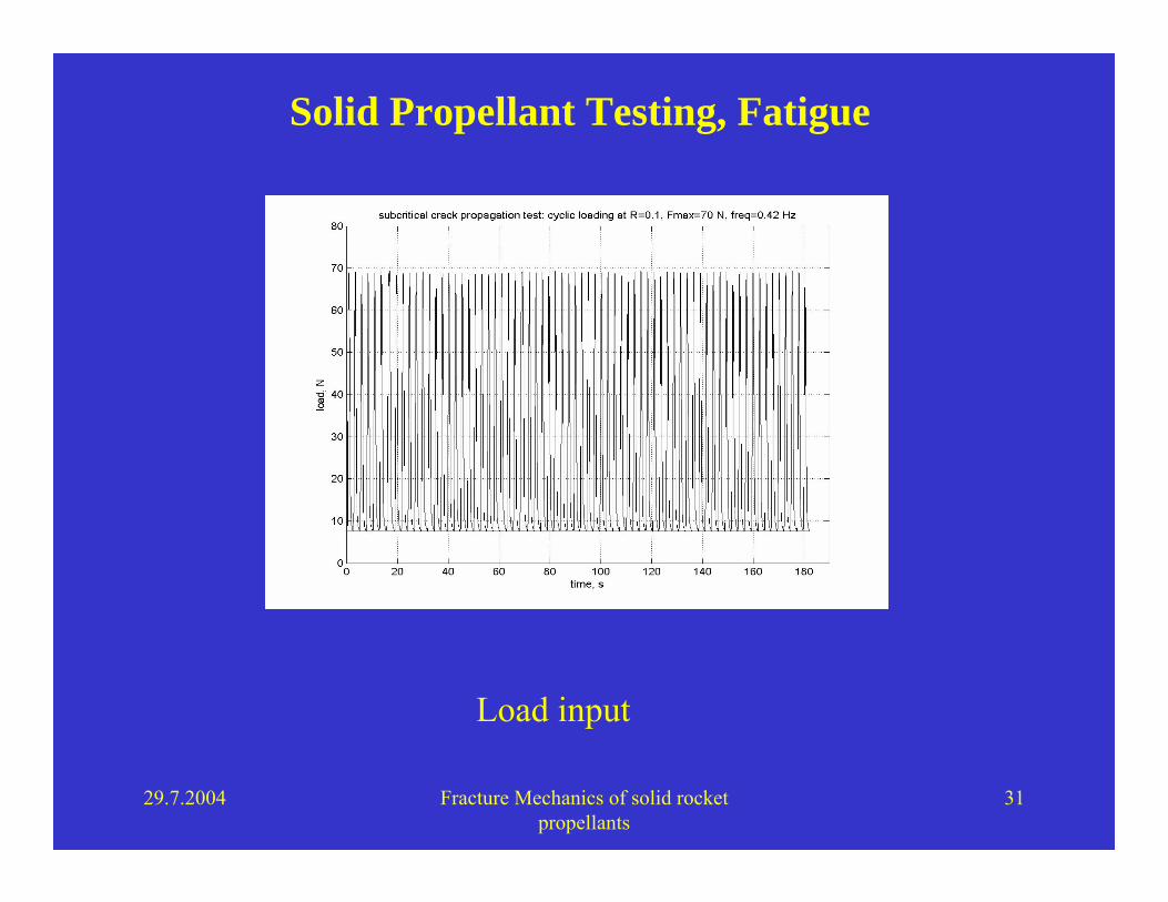
Solid Propellant Testing, Fatigue
Load input
29.7.2004 Fracture Mechanics of solid rocket propellants
31
Solid Propellant Testing, Fatigue
Load input

29.7.2004 Fracture Mechanics of solid rocket propellants
32
Fatigue, crack length measurements
29.7.2004 Fracture Mechanics of solid rocket propellants
33
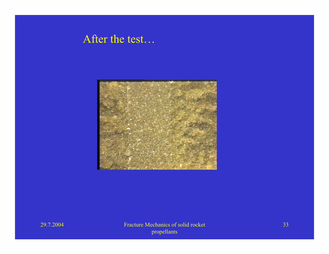
After the test…

29.7.2004 Fracture Mechanics of solid rocket propellants
34
subcritical crack growth
solid propellantAP-HTPB-Al
high burning rate
R 0.1
da/dN = 0.0809(∆Κ)7.5011
R2 = 0.9533
0
0,05
0,1
0,15
0,2
0,25
0,3
0 0,2 0,4 0,6 0,8 1 1,2 1,4
∆Κ, MPa*mm0.5
da/d
N, m
m/c
ycle
Experimental results

29.7.2004 Fracture Mechanics of solid rocket propellants
35
Fatigue, service life computations
Thermal cycling
Initial crack length Number of sustained loads
0.1 mm 863
0.2 mm 132
0.4 mm 22
0.6 mm 9
Computation of the induced stress
Application of exact solutions (2-4)
Propagation until a = a critical, pressurisation

29.7.2004 Fracture Mechanics of solid rocket propellants
36
Fatigue, service life computations

29.7.2004 Fracture Mechanics of solid rocket propellants
37
Solid Propellant Testing, Toughness
Initial crack length
Number of sustained loads
Hours of life
0.1 mm 1.096 e9 6087 hrs
0.2 mm 162’810’000 904.5 hrs
0.4 mm 24’131’000 134.1 hrs
0.6 mm 7'869’000 43.7 hrs
0.8 mm 3'530’400 19.6 hrs
Vibrations, (monochromatic, 50 Hz)

29.7.2004 Fracture Mechanics of solid rocket propellants
38
Solid Propellant Testing, Toughness
ASTM E 399 – D 5045 91a
Pmax
5% secant
P5%=PQ
displacement
load
29.7.2004 Fracture Mechanics of solid rocket propellants
39
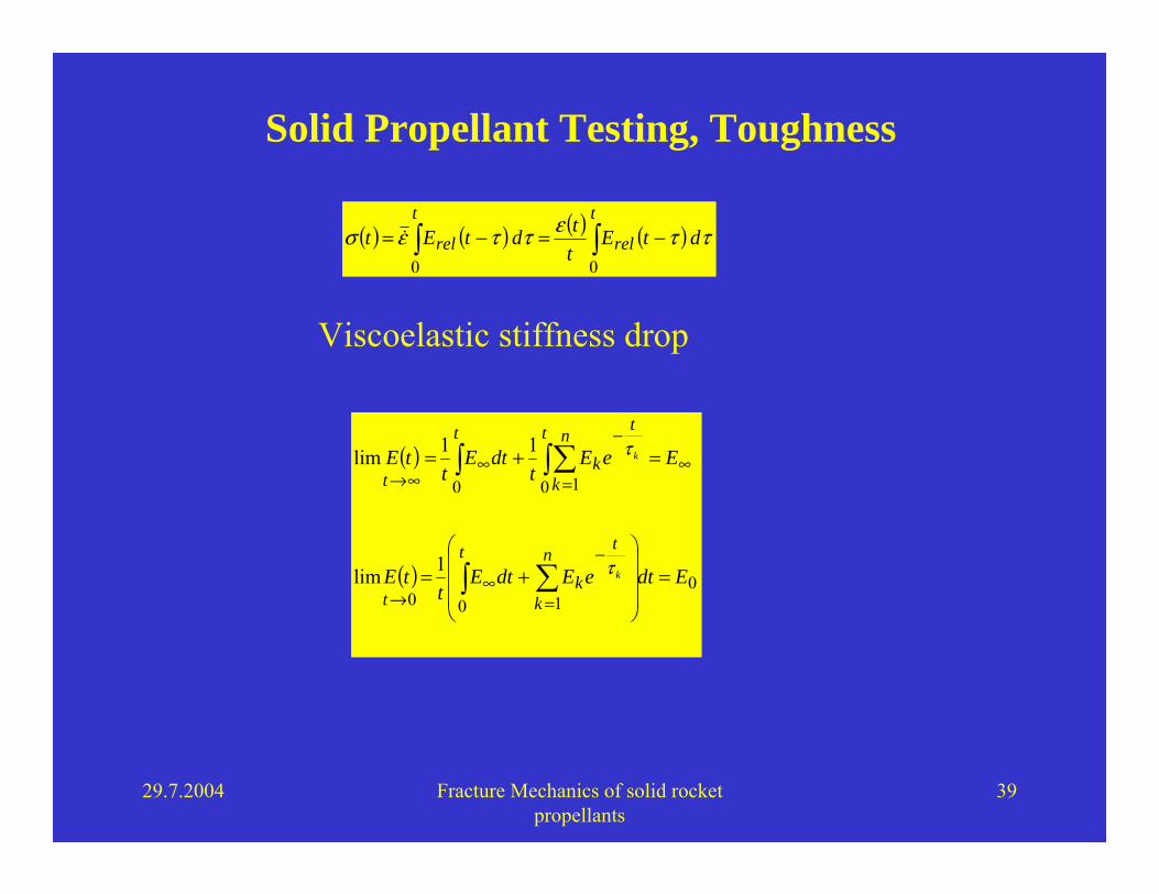
Solid Propellant Testing, Toughness
( ) ( ) ( ) ( ) ττεττεσ dtEttdtEt
t
rel
t
rel ∫∫ −=−=00
( )
( ) 0100
0 10
1lim
11lim
EdteEdtEt
tE
EeEt
dtEt
tE
n
k
t
k
t
t
t n
k
t
k
t
t
k
k
=⎟⎟⎟
⎠
⎞
⎜⎜⎜
⎝
⎛+=
=+=
∑∫
∫∑∫
=
−∞
→
∞=
−∞
∞→
τ
τ
Viscoelastic stiffness drop
29.7.2004 Fracture Mechanics of solid rocket propellants
40
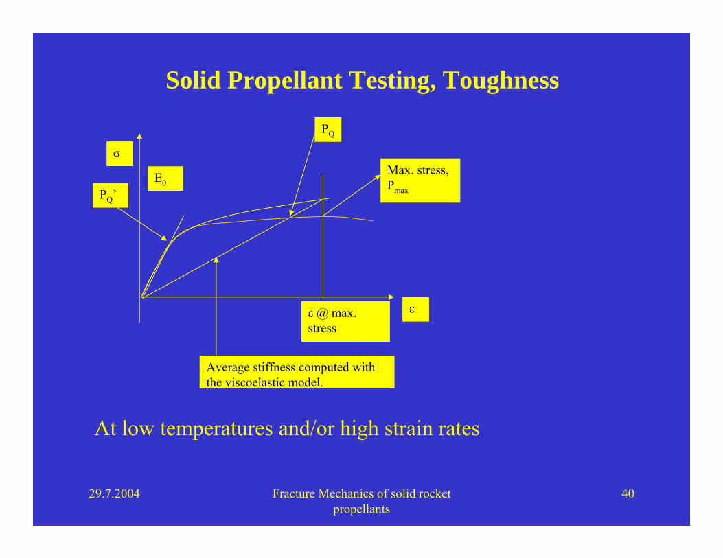
Solid Propellant Testing, Toughness
ε
σ
E0Max. stress,Pmax
ε @ max. stress
PQ’
Average stiffness computed with the viscoelastic model.
PQ
At low temperatures and/or high strain rates

29.7.2004 Fracture Mechanics of solid rocket propellants
41
Temperature Strain Rate Initial Stiffness Maximum stress
71 °C 0.01 mm/min. 2.9 MPa 0.54 MPa
-30 °C 50 mm/min. 15.77 MPa 2.09 MPa
Simulated Toughness test at –30°C and 50 mm/min.

29.7.2004 Fracture Mechanics of solid rocket propellants
42
Toughness, new data analysis methodology
29.7.2004 Fracture Mechanics of solid rocket propellants
43
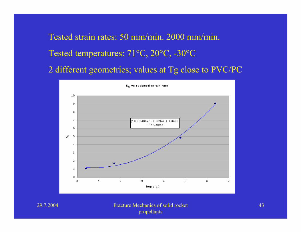
Tested strain rates: 50 mm/min. 2000 mm/min.
Tested temperatures: 71°C, 20°C, -30°C
2 different geometries; values at Tg close to PVC/PC KIC vs r e d u ce d s tr ain r ate
y = 0,2488x 2 - 0,3894x + 1,3433R2 = 0,9944
0
1
2
3
4
5
6
7
8
9
10
0 1 2 3 4 5 6 7
lo g (e 'aT)
K IC
29.7.2004 Fracture Mechanics of solid rocket propellants
44
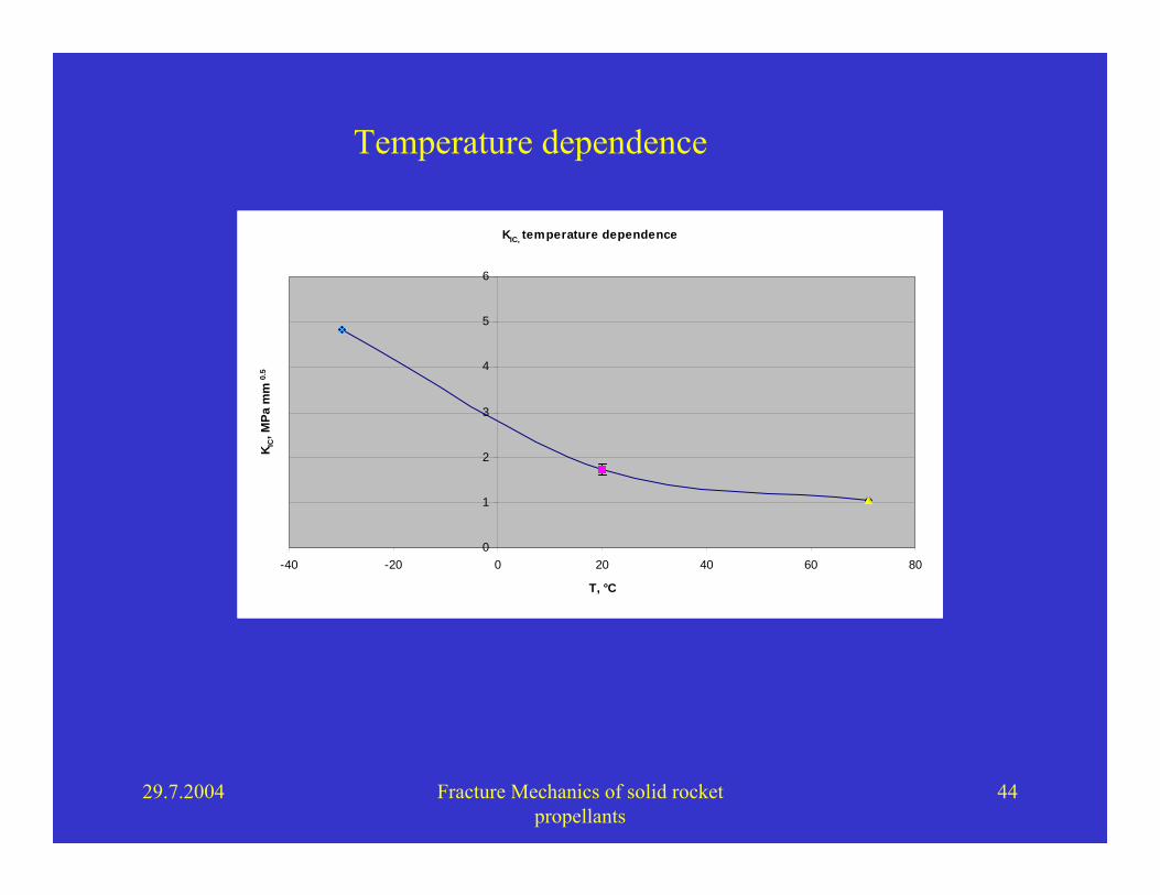
KIC, temperature dependence
0
1
2
3
4
5
6
-40 -20 0 20 40 60 80
T, °C
K IC, M
Pa m
m0.
5
Temperature dependence
29.7.2004 Fracture Mechanics of solid rocket propellants
45
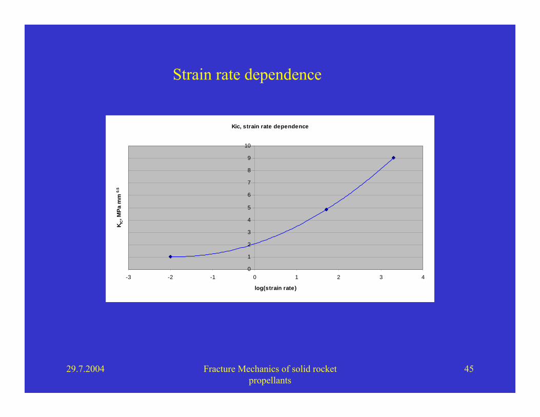
Kic, strain rate dependence
0
1
2
3
4
5
6
7
8
9
10
-3 -2 -1 0 1 2 3 4
log(strain rate)
K IC, M
Pa m
m0.
5
Strain rate dependence
29.7.2004 Fracture Mechanics of solid rocket propellants
46
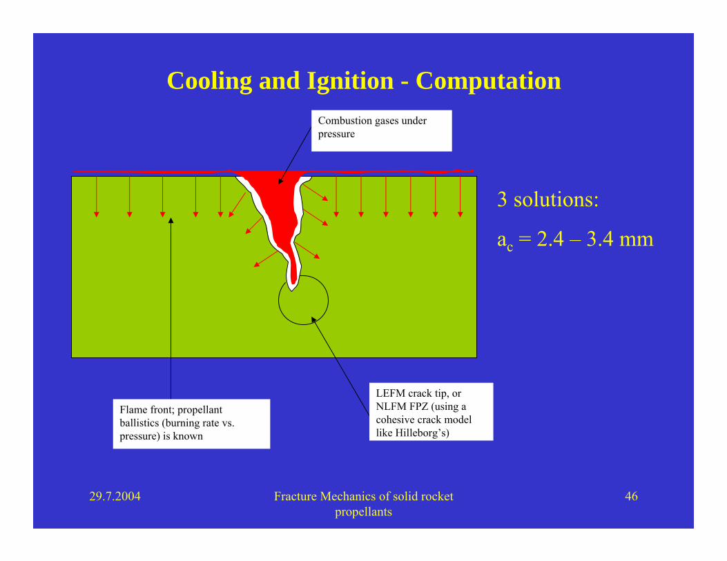
Cooling and Ignition - ComputationCombustion gases under pressure
Flame front; propellant ballistics (burning rate vs.pressure) is known
LEFM crack tip, orNLFM FPZ (using acohesive crack model like Hilleborg’s)
3 solutions:
ac = 2.4 – 3.4 mm

29.7.2004 Fracture Mechanics of solid rocket propellants
47
Conclusions
• Fracture mechanics explains many structural failures
• It can be applied to constitutive and failure modelling of thematerial
• LEFM gives sensible results, FE Analysis with NLFM cohesive elements required
• In Europe we have a similar situation to the one with metals before FM and with Woehler curves / Goodman diagrams
• Application is badly required to reduce testing, improve safety and increase the performance of motors!