Embed Size (px)
Citation preview
THE CONCEPT OF A NEW CAR SHOCK
ABSORBER WITH ENERGY RECUPERATION
KRZYSZTOF SICZEK1, MACIEJ KUCHAR2
Technical University of Lodz
Summary
The concept of a shock absorber able to recuperate from energy chassis vibrations has been presented in the article. Energy released from such vibrations has thus far simply dissipated. The shock absorber is composed of the cylinder, the turbine and the generator. Its dimensions are close to those of hydraulic shock absorber, so the new shock absorber can be used in a typical automobile. The changes for values of dynamic parameters during operation of the new shock absorber components have been estimated using published data. The analysis of dynamics for the shock absorber operating in road conditions has been based on this data. Such analysis has allowed checking the operation correctness of the new design from both the shock absorber and the electric generator point of view. The amount potential of electric power available for recovery in the shock absorber has been estimated for typical road conditions. Such electric power can be used as a comparative parameter in the cost-effectiveness analysis for use of new shock absorbers in automobiles. The model performed of the turbine has been elaborated. Analysis of fluid flows in the model has been carried out and results of it have been shown.
Keywords: shock absorber, energy recuperation, turbine, electric power generator.
Index determinations
A – cross section area of cylinder of the shock absorber, A1 – cross section area of the
upper stator outlet, Ap – pole cross section area, A
Z – magnetic vector potential in Z axis,
B – average magnetic flux density, Br – remanent magnetic flux density, E – electromotive
force, Hc – coercive magnetic flux intensity, J
0 – mass polar moment of inertia, L – the
blade width, M – moment, N – number of winds of coil, R – mean radius of force loading rotor blade, R
c – circuit resistance, U
A – battery voltage, p – fluid pressure in the cylinder
chamber, before the upper stator inlet, r – estimated blade radius, t – time, v – relative rod velocity against the shock absorber cylinder, v
1 – outlet velocity from upper stator, v
2 –
peripheral velocity of rotor, v3 – peripheral velocity of fluid against rotor, – angle of outlet
velocity from upper stator against the rotor axis, – fluid density, – angular velocity
1 Technical University of Lodz, Department of Vehicles and Fundamentals of Machine Design, 116 Żeromskiego Street, 90-924 Lodz, e-mail: [email protected], ph.: +48 42 631 22 50
2 Technical University of Lodz, Department of Vehicles and Fundamentals of Machine Design, 116 Żeromskiego Street, 90-924 Lodz, e-mail: [email protected], ph.: +48 42 631 22 55
Krzysztof Siczek, Maciej Kuchar50
1. Introduction
The automobile moving on rough road is loaded by stochastic vertical inputs, which act on
its wheel. All of such inputs are independent of each other. Their intensity is proportional
to the vehicle speed, almost linearly. Such inputs acting on the automobile wheels initiate
vibrations during driving, which are noticed by the driver or passengers as they can cre-
ate discomfort. Therefore, vehicle designers try to isolate these vibrations from the body
by a set of springs and to damp on them by a set of shock absorbers, usually one shock
absorber falls on one wheel. In most cases, hydraulic shock absorbers are used in which
the energy of vehicle vibrations is precipitated on the flow of hydraulic fluid through the
system throttling valves. The energy of the fluid is converted into heat and into used up in
the work for overcoming the flow resistance and, therefore, is lost forever.
Such energy, however, may be changed into useful electric power, with the help of
additional turbogenerator.
At least part of the energy may be recovered, without significantly decreasing the lev-
el of vibration damping, which is provided in most vehicles by classic hydraulic shock
absorbers.
The object of research presented in this paper has been a set of hydraulic shock absorber
with axial turbine and of electric power generator using permanent magnets.
The aim of the present paper is to investigate the performance of the new shock absorber
for different speed of automobile and road conditions.
2. Description of the new hydraulic shock absorber
with energy recuperation
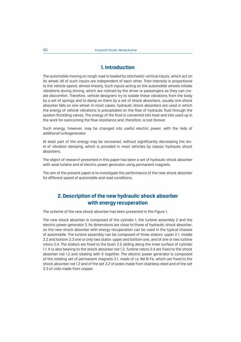
The scheme of the new shock absorber has been presented in the Figure 1.
The new shock absorber is composed of the cylinder 1, the turbine assembly 2 and the
electric power generator 3. Its dimensions are close to those of hydraulic shock absorber,
so the new shock absorber with energy recuperation can be used in the typical chassis
of automobile. The turbine assembly can be composed of three stators: upper 2.1, middle
2.2 and bottom 2.3 one or only two stator: upper and bottom one, and of one or two turbine
rotors 2.4. The stators are fixed to the bush 2.5 sliding along the inner surface of cylinder
1.1. It is also bearing to the shock absorber rod 1.2. Turbine rotors 2.4 are fixed to the shock
absorber rod 1.2 and rotating with it together. The electric power generator is composed
of the rotating set of permanent magnets 3.1, made of i.e. Nd-B-Fe, which are fixed to the
shock absorber rod 1.2 and of the set 3.2 of poles made from stainless steel and of the set
3.3 of coils made from copper.
The concept of a new car shock absorber with energy recuperation 51
Fig. 1. The scheme of the new shock absorber. 1 – cylinder, 2 – turbine assembly, 3 – electric power generator,
1.1 – inner surface of cylinder, 1.2 - shock absorber rod, 2.1 – upper stator, 2.2 – middle stator,
2.3 – bottom stator, 2.4 – turbine rotor, 3.1 – set of permanent magnets, 3.2 – set of poles,
3.3 – set of coils
3
3.3
2.5
1,2
2.1
2.2
2.3
2.4
21
1.1
3.2 3.1
3. The model of road roughness and of moving masses
for vehicle
The road quality is usually evaluated on the base of the spectral power density for road
microprofile. The representative model of road roughness analyzed has been established,
basing on the data from [1, 2].
Krzysztof Siczek, Maciej Kuchar52
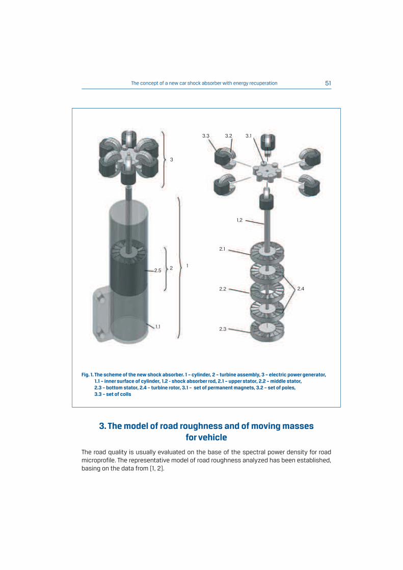
Fig. 2. The spectral density of road roughness GS vs. relative frequency
S; A – asphalt surface in good
conditions, B – asphalt surface in poor conditions set of poles, C – paved surface
Fig. 3. Road microprofile samples generated basing on values of their spectral power density vs. road length l;
A – asphalt surface in good conditions, B – asphalt surface in poor conditions, C – paved surface
The spectral density of road roughness, for different surface conditions has been shown
in the figure 2. The road profile samples have been generated based on such values and
using Inverse Fast Fourier Transform, (Fig. 3).
Such values have been used for the excitation of the wheel in the model of moving vehicles.
The chassis and the body of the vehicle and its wheels have been modeled as the set
1, E-03
1, E-05
1, E-04
1, E-06
1, E-07
0,01 0,1 101
Gs [
m3/r
ad
]
S [rad/m]
[mm]
l [m]
[m3/rad]
A
B
C
The concept of a new car shock absorber with energy recuperation 53
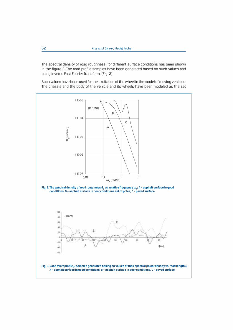
Fig. 4. The modeled set of moving masses for vehicle: the chassis and body and the wheel;
A – excitation (vibrations) from road profile, B – tire (stiffness 37 N/mm, damping coefficient 0.15 Ns/mm),
C – unsprung mass, D – spring (stiffness 28 N/mm), E - ¼ mass of vehicle (250 kg), F – shock absorber
(nonlinear damping coefficient)
4. Analysis on the fluid flow in the turbine assembly
The turbine operates in nonstationary conditions, which makes the analysis of the flow
very difficult. Equations for the calculation of axial turbines presented in [8] have been
elaborated for conditions of constant rotational velocityof turbine rotor. To simplify the
analysis, adiabatic flow of noncompresible hydraulic fluid has been assumed. In reality
fluid density can change because of gas bubble initiation or pressure changes. Some heat
transfer exists between the fluid and the material of turbine elements, in conditions of
high temeprature gradients arising during fluid flow. Such changes are of local character
and thus the need to accept the pressure and density values has been recognised, which
have been averaged over the time.
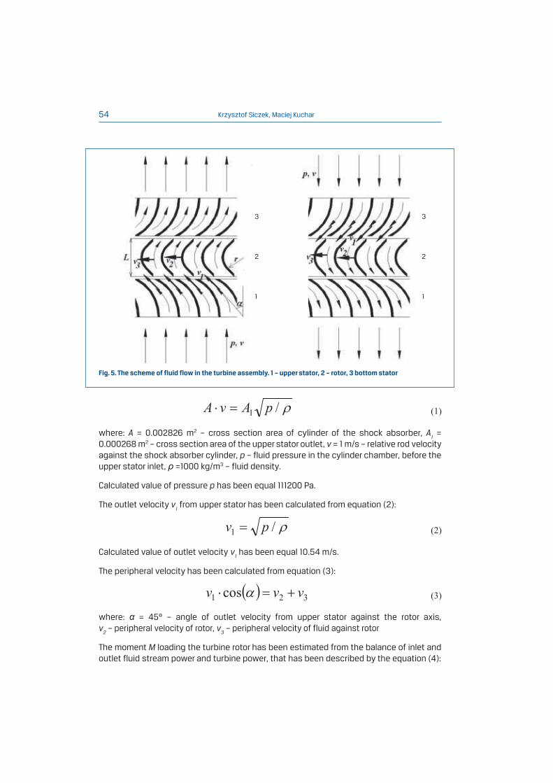
The scheme of fluid flow in the turbine assembly has been shown in the figure 5.
The fluid pressure p (fig. 5) in the cylinder chamber, before the upper stator inlet, have been
estimated from the equation (1):
E
C
F D
B
A
of two vibrating masses (Figure 4). Such set has been of two degree of freedom. The first
mass has been the wheel with the stiffness and damping of its tyre. The second mass has
been equal to ¼ of all vehicle mass and it has been associated with the stiffness of the
wheel spring and with the nonlinear damping of wheel shock absorber. The characteristic
data have been taken from [3].
Krzysztof Siczek, Maciej Kuchar54
Fig. 5. The scheme of fluid flow in the turbine assembly. 1 – upper stator, 2 – rotor, 3 bottom stator
where: A = 0.002826 m2 – cross section area of cylinder of the shock absorber, A1 =
0.000268 m2 – cross section area of the upper stator outlet, v = 1 m/s – relative rod velocity
against the shock absorber cylinder, p – fluid pressure in the cylinder chamber, before the
upper stator inlet, =1000 kg/m3 – fluid density.
Calculated value of pressure p has been equal 111200 Pa.
The outlet velocity v1 from upper stator has been calculated from equation (2):
Calculated value of outlet velocity v1 has been equal 10.54 m/s.
The peripheral velocity has been calculated from equation (3):
where: = 45° – angle of outlet velocity from upper stator against the rotor axis,
v2 – peripheral velocity of rotor, v
3 – peripheral velocity of fluid against rotor
The moment M loading the turbine rotor has been estimated from the balance of inlet and
outlet fluid stream power and turbine power, that has been described by the equation (4):
3 3
2 2
1 1
The concept of a new car shock absorber with energy recuperation 55
From the second hand the moment M has been calculated from equation (5):
where: r = 0.0105 m – estimated blade radius, R = 0.029 m – mean radius of force loading
rotor blade, L = 0.012 m – the blade width.
Calculated value of velocity v2 has been equal 5.53 m/s, what has corresponded for turbine
rotational speed 1820 rpm. The calculated value of velocity v3 wynosiła 1.93 m/s, has been
equal 1.93 m/s, what has corresponded for rotor moment M equal 0.62 Nm. The calculated
turbine power has been equal 0.118 kW.
5. Model of electric power generator
The electric power generator utilizes the known phenomenon of EMF generation in coil
winds 3.3 on the poles 3.2 (fig. 1), in result of magnetic flux changes in magnetic circuits
containing such poles 3.2 [9, 10]. Such changes arise during motion of permanent
magnets 3.1 in magnetic circuits, perpendicular to mean symmery planes of the circuits
(poles 3.2 – fig. 1). Magnetic flux in such magnetic circuit increases nonlinearly, until
peaking and then it decreases almost symmetrically. In order to obtain a higher electric
efficiency of generator, its coils can be arranged into the 3-phase set [9, 10]. The model
of electric power generator have been made using FEM. To simplify the analysis, the cyclic
symmetry concept has been used, so that only a part of electric power generator has
been taken into consideration. Such simplification could be supported with the fact of
cyclic symmetry existence for the structure of fixed generator, for current flow and for
magnetic field gradient. The model consisted of a permanent magnet 4 made of Nd-B-Fe
(Hc = 850000 A/m, B
r = 1.2 T), a steel pole 3 and copper coil 2. Such assembly has been
positioned in the block of air 1. The analysis has been made for a number of steady angular
positions of the permanent magnets assembly in respect to the poles assembly, so it has
been analyzed in a steady state only. For reasons of simplicity, the steady-state analysis
has been made. It has been assumed, that magnet motion can change values of vector
magnetic potential in the assembly, not more than about 5% in comparison to the fixed
case. The grid of finite elements has been generated automatically, by commercial program
ANSYS [11]. The boundary conditions have been following: on each external surface of the
mentioned air block the vector magnetic potential value has been equal zero. The model,
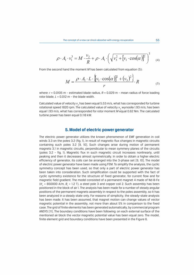
finite element grid and boundary conditions have been presented in the Figure 6.
Krzysztof Siczek, Maciej Kuchar56
Fig. 6. The model of electric power generator, grid of finite elements and boundary conditions. 1 – air block,
2 – coil, 3 – pole, 4 – permanent magnet
1 2 3 4 A=0
A=0
Moment M(t) loading rotor has been calculated from equation (6):
where: J0 – mass polar moment of inertia, E – electromotive force, – angular velocity,
N – number of winds of coil, t – time, Rc – circuit resistance, B – average magnetic
flux density, Ap – pole cross section area, U
A – battery voltage
6. Results of calculations
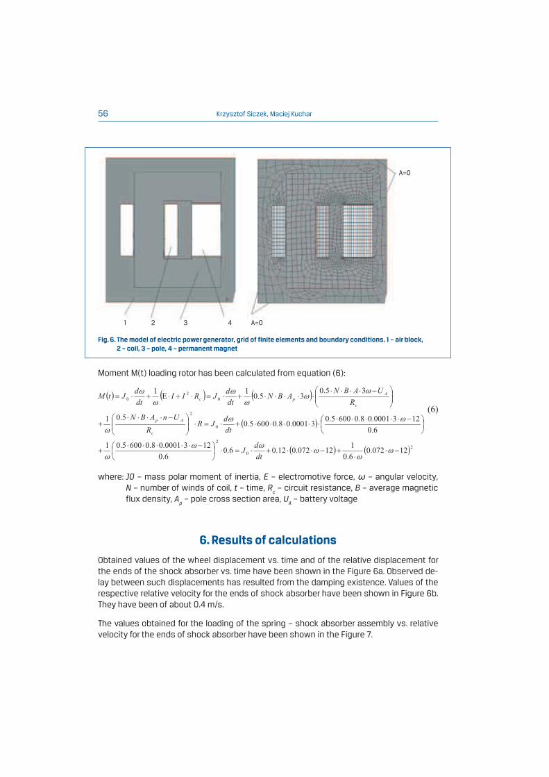
Obtained values of the wheel displacement vs. time and of the relative displacement for
the ends of the shock absorber vs. time have been shown in the Figure 6a. Observed de-
lay between such displacements has resulted from the damping existence. Values of the
respective relative velocity for the ends of shock absorber have been shown in Figure 6b.
They have been of about 0.4 m/s.
The values obtained for the loading of the spring – shock absorber assembly vs. relative
velocity for the ends of shock absorber have been shown in the Figure 7.
The concept of a new car shock absorber with energy recuperation 57
Fig. 7. a) The displacement vs. time 1 - of wheel, 2 - relative for the ends of shock absorber,
b) the relative velocity for the ends of shock absorber
Fig. 8. Loading of the set spring – shock absorber vs. relative velocity for the ends of shock absorber
a) b)t[s]
y[m
m] y
a[m
m]
Fs-s
a[N
]
v[m
m/s
]
v[mm/s]
t[s]
The irregular shape of such curves has probably resulted from nonlinear damping of shock
absorber. As could be predicted the loading of the spring – shock absorber assembly is 3-5
times greater than that of the shock absorber alone. It is similar to the case of the classic
hydraulic shock absorber.
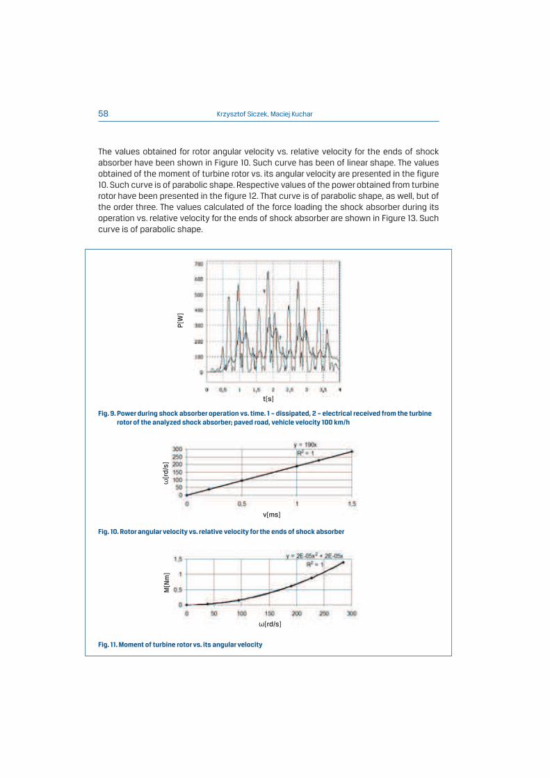
Calculated values for the dissipated power during shock absorber operation vs. time have
been presented in the Figure 9. The overage value of the power, dissipated during 4 s, has
been equal 171 W. The average value of the electrical power received from the turbine rotor,
in the same period, was equal 108 W.
Krzysztof Siczek, Maciej Kuchar58
Fig. 9. Power during shock absorber operation vs. time. 1 – dissipated, 2 – electrical received from the turbine
rotor of the analyzed shock absorber; paved road, vehicle velocity 100 km/h
Fig. 10. Rotor angular velocity vs. relative velocity for the ends of shock absorber
Fig. 11. Moment of turbine rotor vs. its angular velocity
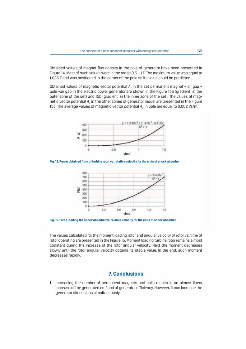
The values obtained for rotor angular velocity vs. relative velocity for the ends of shock
absorber have been shown in Figure 10. Such curve has been of linear shape. The values
obtained of the moment of turbine rotor vs. its angular velocity are presented in the figure
10. Such curve is of parabolic shape. Respective values of the power obtained from turbine
rotor have been presented in the figure 12. That curve is of parabolic shape, as well, but of
the order three. The values calculated of the force loading the shock absorber during its
operation vs. relative velocity for the ends of shock absorber are shown in Figure 13. Such
curve is of parabolic shape.
P[W
]
M[Nm]
t[s]
v[ms]
[rd/s]
[rd/s]
The concept of a new car shock absorber with energy recuperation 59
Fig. 12. Power obtained from of turbine rotor vs. relative velocity for the ends of shock absorber
Fig. 13. Force loading the shock absorber vs. relative velocity for the ends of shock absorber
v[ms]
v[ms]
P[W
]
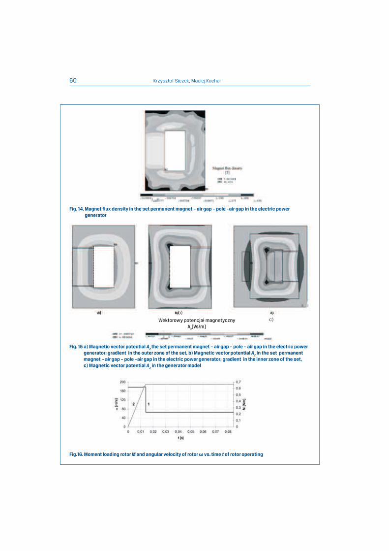
Obtained values of magnet flux density in the pole of generator have been presented in
Figure 14. Most of such values were in the range 0.5 – 1 T. The maximum value was equal to
1.635 T and was positioned in the corner of the pole so its value could be predicted.
Obtained values of magnetic vector potential AZ in the set permanent magnet – air gap –
pole –air gap in the electric power generator are shown in the Figure 15a (gradient in the
outer zone of the set) and 15b (gradient in the inner zone of the set). The values of mag-
netic vector potential AZ in the other zones of generator model are presented in the Figure
15c. The average values of magnetic vector potential AZ in pole are equal to 0.002 Vs/m.
F[N]
The values calculated for the moment loading rotor and angular velocity of rotor vs. time of
rotor operating are presented in the Figure 15. Moment loading turbine rotor remains almost
constant during the increase of the rotor angular velocity. Next the moment decreases
slowly until the rotor angular velocity obtains its stable value. In the end, such moment
decreases rapidly.
7. Conclusions
1. Increasing the number of permanent magnets and coils results in an almost linear
increase of the generated emf and of generator efficiency. However, it can increase the
generator dimensions simultaneously.
Krzysztof Siczek, Maciej Kuchar60
Fig. 14. Magnet flux density in the set permanent magnet – air gap – pole –air gap in the electric power
generator
Fig.16. Moment loading rotor M and angular velocity of rotor vs. time t of rotor operating
Fig. 15 a) Magnetic vector potential AZ the set permanent magnet – air gap – pole – air gap in the electric power
generator; gradient in the outer zone of the set, b) Magnetic vector potential AZ in the set permanent
magnet – air gap – pole –air gap in the electric power generator; gradient in the inner zone of the set,
c) Magnetic vector potential AZ in the generator model
a) b)
Wektorowy potencjał magnetyczny
Az[Vs/m]
c)
The concept of a new car shock absorber with energy recuperation 61
2. Rotor angular velocity increases with the relative velocity for the ends of shock absorber almost linearly.
3. Moment driving the turbine rotor increases with its angular velocity in parabolic way. Respective values of the power obtained from turbine rotor increases in the way of parabolic of the order three.
4. Moment loading turbine rotor is almost constant during begin increasing of the rotor angular velocity, then it decreases slowly until the rotor angular velocity obtains its stabile value. After it, the moment loading turbine rotor decreases rapidly.
5. Force loading the shock absorber during its operation increases with the relative velocity for the ends of shock absorber in the parabolic way.
6. It is possible to obtain a value of electrical power up to 118 W from the described shock absorber.
References
[1] KUCHAR M., SICZEK K.: Ocena możliwości odzyskiwania energii z układu zawieszenia przy wykorzystaniu
amortyzatora pneumatycznego, Archiwum Motoryzacji 2/2011, pp. 21-37.
[2] AVADHANY S.N.: Analizes of hydraulic Power Transductin in Regenerative Rotary Shock Absorber as Function
of Working Fluid Kinematic Viscosity. S.B. Materials of Science & Engineering Massachusetts Institute of Technology, 2009.
[3] KAMIŃSKI E., POKORSKI J.: Dynamika zawieszeń i układów napędowych pojazdów samochodowych, WKŁ, Warszawa, 1983.
[4] SAYERS M.W., KARAMIHAS S.M.: The basic information and measurement road profiles, University of Michigan, 1998.
[5] RAO M.D., GRUENBERG S.: Measurement of Equivalent Stiffness and Damping of Shock Absorbers, Michigan Technological University, Houghton, MI 49931, USA.
[6] EMAM M.A.A., SHAABAN S., EL-DEMERDASH S., EL-ZOMOR H.: A tyre-terrain interaction model for off-road
vehicles, Journal of Mechanical Engineering Research Vol. 3(7), pp. 226-238, July 2011
[7] ŚLĄZKI G., PIKOSZ H.: Wpływ zmian tłumienia w zakresie zmienności charakterystyki amortyzatora na pionowe
obciążenia dynamiczne kół, Transcomp – XIV International Conference Computer Systems Eided Science, Industry and Transport.
[8] AINLEY D.G., MATHIESONA G.C.R.: Method of Performance Estimation for Axial-Flow Turbines, London: Her Majesty’s Stationery Office 1957.
[9] PLAMITZER A. M.: Maszyny Elektryczne, PWN, Warszawa 1982.
[10] CHEDA W., MALSKI M.: Silniki, Wydawnictwo Komunikacji i Łączności, Warszawa 1984.
[11] ANSYS v.12 help on-line documentation.