Embed Size (px)
Citation preview
See discussions, stats, and author profiles for this publication at: https://www.researchgate.net/publication/286934043
THE DEVELOPMENT AND APPLICATION OF GUIDANCE DOCUMENTS FOR
GROUND CONTROL FOR SLURRY AND EPB TBM TUNNELLING IN HONG KONG
Conference Paper · November 2015
CITATIONS
3
READS
495
4 authors, including:
Some of the authors of this publication are also working on these related projects:
SCL 1103 Hong Kong View project
Assessing the variability of the Jurong Formation in Singapore View project
Nick Shirlaw
Golder Associates
112 PUBLICATIONS 371 CITATIONS
SEE PROFILE
David Salisbury
MTR Corporation
2 PUBLICATIONS 3 CITATIONS
SEE PROFILE
Pui Loi Richard Pang
Ex-Geotechnical Engineering Office
12 PUBLICATIONS 82 CITATIONS
SEE PROFILE
All content following this page was uploaded by Nick Shirlaw on 16 December 2015.
The user has requested enhancement of the downloaded file.
International Conference on Tunnel Boring Machines in Difficult Grounds (TBM DiGs)
Singapore, 18–20 November 2015 THE DEVELOPMENT AND APPLICATION OF GUIDANCE DOCUMENTS FOR GROUND CONTROL FOR SLURRY AND EPB TBM TUNNELLING IN HONG KONG Nick Shirlaw1, David Salisbury2, Patrick Chau3, P.L.R. Pang4
1Golder Associates (Singapore) Pte Ltd., Singapore. Email: [email protected] 2Mass Transit Railway Corporation, Hong Kong. Email: [email protected] 3Geotechnical Engineering Office, Hong Kong. Email: [email protected] 4Geotechnical Engineering Office, Hong Kong. Email: [email protected] ABSTRACT: The Geotechnical Engineering Office (GEO) of the Civil Engineering and Development Department in Hong Kong published GEO Report No. 249, on ground control for slurry TBM tunnelling in 2009. The companion report GEO Report No. 298, for EPB TBM tunnelling, was published in 2014. These reports serve as a basis for the review of geotechnical control submissions made by practitioners on slurry and Earth Pressure Balance (EPB) TBM tunnelling proposals, for consultation with the Hong Kong Special Administrative Region Government (HKSARG). The reports provide a framework for the calculation of the face and tail void grouting pressures required to guard against Ultimate and Serviceability Limit States, under the ground and groundwater conditions commonly encountered in Hong Kong. They also provide guidance for the calculation of compressed air pressures for TBM interventions. The risk of localized settlement (potentially leading ultimately to a sinkhole) and heave (potentially leading to a blow-out) is considered, with guidance on the risk factors involved in such events. The genesis of the reports, and what was included and excluded in terms of content is discussed. The methods outlined in the reports have been applied on a number of completed or ongoing TBM tunnel projects. The methods have generally proven robust, but appear to be slightly conservative, in practice. The experience of working to the reports will be outlined, with comments on issues arising from that experience. KEYWORDS: TBM; Slurry; EPB; Saprolite; Weathering; Sinkhole; Intervention; ULS; SLS 1. INTRODUCTION
The Geotechnical Engineering Office (GEO) of the Civil Engineering and Development Department (CEDD) in Hong Kong exercises geotechnical control on tunnel works in Hong Kong to protect public safety. In order to facilitate the control, the GEO published GEO Report No. 249, on ground control for slurry TBM tunnelling in 2009 (Pang, 2011). The companion report GEO Report No. 298, for EPB TBM tunnelling, was published in 2014. The core of these reports provides guidance on the calculation of the necessary support pressures in order to design against occurrence of ultimate limit states and serviceability limit states. In order to meet SLS requirements, the appropriate minimum support pressure needs to be applied at the face, along the skin and at the tail void (by grouting) of the TBM, during TBM driving and during interventions.
This paper will discuss the genesis of these reports, how they were developed, and present some experience with the application of the guidelines outlined in them.
289 of 691
2. GENESIS OF REPORTS
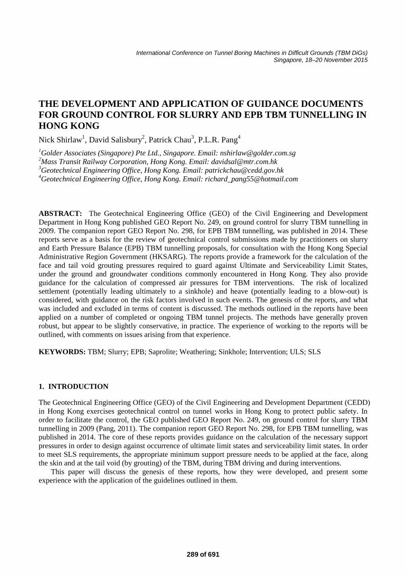
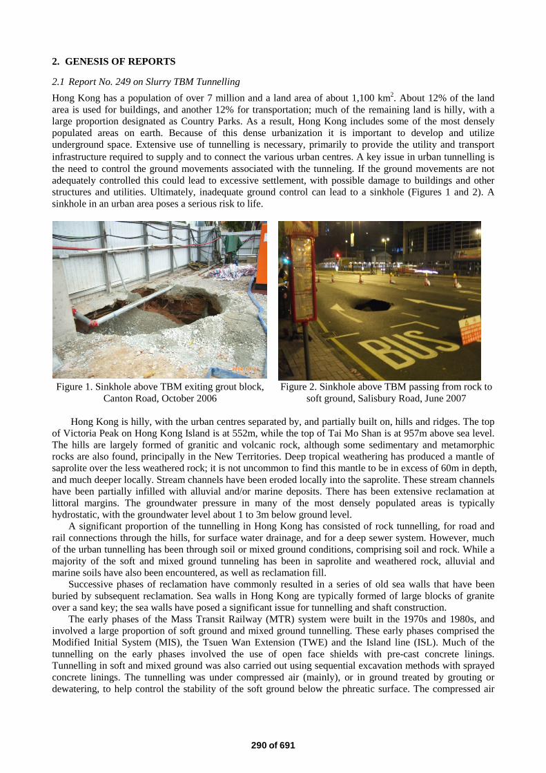
2.1 Report No. 249 on Slurry TBM Tunnelling Hong Kong has a population of over 7 million and a land area of about 1,100 km2. About 12% of the land area is used for buildings, and another 12% for transportation; much of the remaining land is hilly, with a large proportion designated as Country Parks. As a result, Hong Kong includes some of the most densely populated areas on earth. Because of this dense urbanization it is important to develop and utilize underground space. Extensive use of tunnelling is necessary, primarily to provide the utility and transport infrastructure required to supply and to connect the various urban centres. A key issue in urban tunnelling is the need to control the ground movements associated with the tunneling. If the ground movements are not adequately controlled this could lead to excessive settlement, with possible damage to buildings and other structures and utilities. Ultimately, inadequate ground control can lead to a sinkhole (Figures 1 and 2). A sinkhole in an urban area poses a serious risk to life.
Figure 1. Sinkhole above TBM exiting grout block,
Canton Road, October 2006 Figure 2. Sinkhole above TBM passing from rock to
soft ground, Salisbury Road, June 2007
Hong Kong is hilly, with the urban centres separated by, and partially built on, hills and ridges. The top of Victoria Peak on Hong Kong Island is at 552m, while the top of Tai Mo Shan is at 957m above sea level. The hills are largely formed of granitic and volcanic rock, although some sedimentary and metamorphic rocks are also found, principally in the New Territories. Deep tropical weathering has produced a mantle of saprolite over the less weathered rock; it is not uncommon to find this mantle to be in excess of 60m in depth, and much deeper locally. Stream channels have been eroded locally into the saprolite. These stream channels have been partially infilled with alluvial and/or marine deposits. There has been extensive reclamation at littoral margins. The groundwater pressure in many of the most densely populated areas is typically hydrostatic, with the groundwater level about 1 to 3m below ground level.
A significant proportion of the tunnelling in Hong Kong has consisted of rock tunnelling, for road and rail connections through the hills, for surface water drainage, and for a deep sewer system. However, much of the urban tunnelling has been through soil or mixed ground conditions, comprising soil and rock. While a majority of the soft and mixed ground tunneling has been in saprolite and weathered rock, alluvial and marine soils have also been encountered, as well as reclamation fill.
Successive phases of reclamation have commonly resulted in a series of old sea walls that have been buried by subsequent reclamation. Sea walls in Hong Kong are typically formed of large blocks of granite over a sand key; the sea walls have posed a significant issue for tunnelling and shaft construction.
The early phases of the Mass Transit Railway (MTR) system were built in the 1970s and 1980s, and involved a large proportion of soft ground and mixed ground tunnelling. These early phases comprised the Modified Initial System (MIS), the Tsuen Wan Extension (TWE) and the Island line (ISL). Much of the tunnelling on the early phases involved the use of open face shields with pre-cast concrete linings. Tunnelling in soft and mixed ground was also carried out using sequential excavation methods with sprayed concrete linings. The tunnelling was under compressed air (mainly), or in ground treated by grouting or dewatering, to help control the stability of the soft ground below the phreatic surface. The compressed air
290 of 691
pressure used for this tunnelling was based on trials (Haswell et al., 1980) and determined by observation, rather than by calculation.
Earth Pressure Balance (EPB) TBMs were used to drive tunnels for part of the West Rail line (completed in 2003), and for the Lok Ma Chau Spur line tunnels (completed in 2007). Slurry TBMs were used for the Kai Tak drainage tunnel (completed in 2004) and part of the Kowloon Southern Link (KSL), completed in 2008.
Detailed calculations of operating pressure were prepared in advance of the slurry shield tunnelling for the KSL. Advice on the basis for these calculations was provided by an expert from the US employed by the contractor, and review, with independent calculations, was carried out by another international expert employed by the GEO. The approaches used for the calculations and checking were based on published papers and experience from outside Hong Kong.
The West Rail and Kowloon Southern Link involved a limited length of pressurized TBM tunnelling. However, under the Railway Development Strategy 2000 the HKSARG outlined a number of new railway lines. These were subsequently implemented as five major railway projects: West Island Line, South Island Line (East), Shatin to Central Link, Express Rail Link and Kwun Tong Line Extension. In addition to these railway projects, major drainage and road projects were also being planned. Extensive tunnelling would be required for many of the projects. These projects are either still under construction or recently opened (as of mid-2015). As the planning of the projects developed, it became apparent that there would be a major increase in the use of pressurized TBMs in Hong Kong.
There had been two major, but localized, incidents of loss of ground during the construction of the KSL tunnels using a large diameter slurry TBM (Pang, 2011; Pang, 2014). Localized, but large, settlements and sinkholes had been documented over EPB tunnels in Singapore (Shirlaw et al., 2003) and over slurry and EPB shields elsewhere (Shirlaw et al., 2003; BTS/ICE, 2005). The need for a basis for detailed assessment of the appropriate operating support pressures and procedures for pressurized TBMs, as a risk control measure for such incidents, was evident. For the design and construction of deep cut and cover excavations, there was extensive experience within Hong Kong, and relevant standards and guidance documents were available. In comparison, at the time, there was limited experience in Hong Kong with pressurized TBM tunnelling, particularly the calculation of the critical support pressures required. There were no standards for such calculations. Although there were published papers outlining the basis for the calculations, these were scattered in a variety of publications, and there was no common basis on how they should be applied in practice.
It was considered that, with guidance and training, GEO staff would be able to undertake the review of operating support pressure calculations, carried out by contractors and consultants, for slurry and EPB TBMs. A guidance document was therefore prepared; which was initially intended for internal use within GEO.
The first draft of the guidance document was produced by the end of 2007, largely based on expert advice and review material produced for the KSL project and the general success of the TBM tunnelling undertaken on that project. However, during the review of the draft, a question was raised on the use of the document. If it was for GEO internal use only, contractors and consultants would be making submissions to GEO without being aware of the basis on which their submissions were being reviewed. Rather than keeping the document for internal use only, it was considered appropriate to make it available to the industry. This, in turn, meant that it was necessary to have the document peer reviewed by a group of experienced professionals, representing a cross-section of the industry, prior to issue. After peer review and further editing, the document was finally issued in early 2009, as GEO Report No. 249 Ground Control for Slurry TBM Tunnelling in Hong Kong, with a soft copy version that could be downloaded for free from the CEDD website. There are numerous other geotechnical guidance documents and reports available for downloading on the CEDD website, and the guidance document became the next report in the numerical sequence. 2.2 Report No. 298 on EPB TBM Tunnelling
Report No. 249 was prepared following the experience of the KSL project, and was specific to slurry TBM tunnelling. However, this immediately raised the question as to what extent the document could be applied to EPB TBM tunnelling. The Working Group on Cavern and Tunnel Engineering of the Hong Kong Institution of Engineers’ Geotechnical Division, which is made up of industry and government representatives, took it upon themselves to prepare a draft guidance document. The draft document went through a similar peer review process as Report No. 249, and the final document, GEO Report No. 298 Ground Control for EPB TBM Tunnelling in Hong Kong, was issued in 2014.
291 of 691
3. TECHNICAL CONTENT
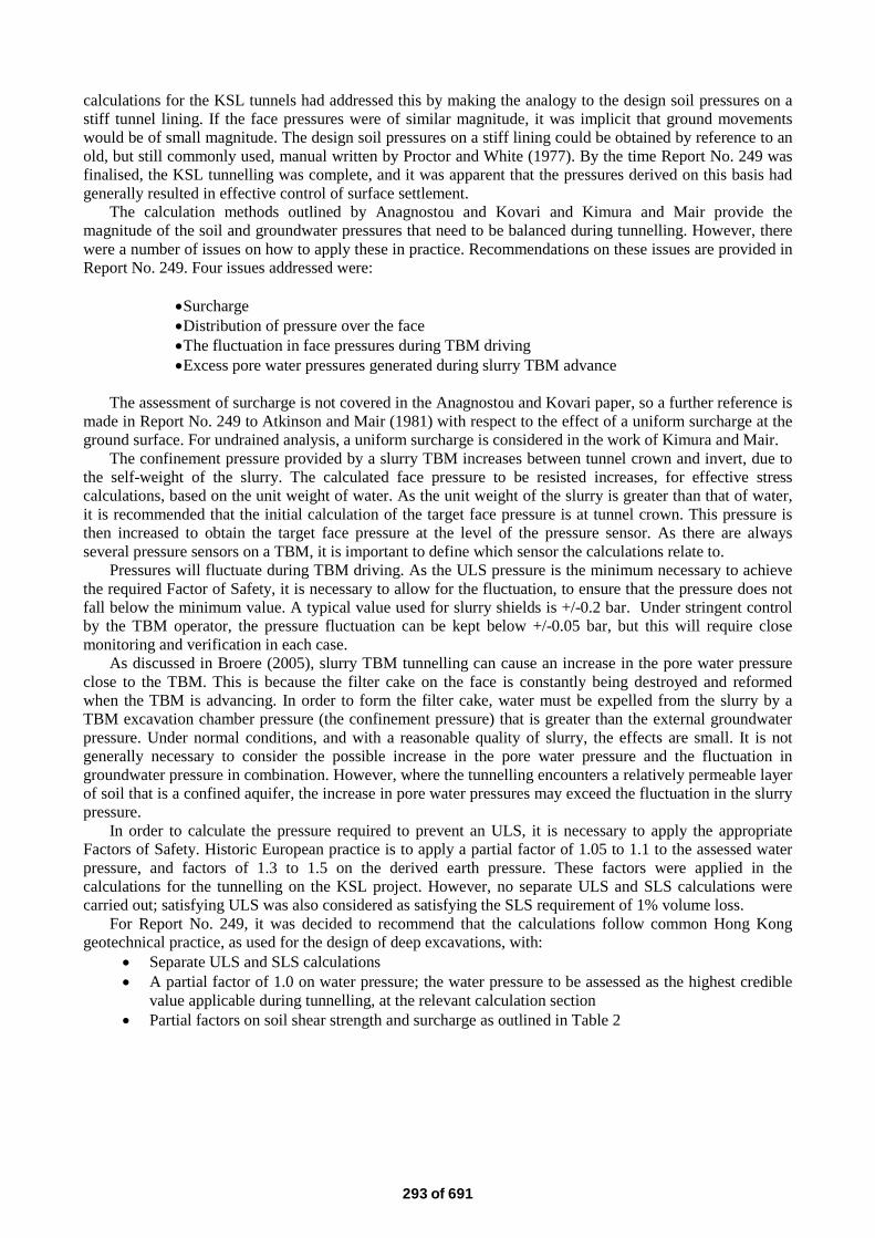
3.1 Report No. 249 The section titles and respective number of pages for Report No. 249 are given in Table 1.
Table 1. Summary of the sections in Report No. 249
Section title Number of pages Scope and objectives 1 Symbols and glossary 1
Slurry pressure assessment 22 Tail void grouting 2
Excavation Management System (volume measurement) 2
High Risk Activities 2 References, Tables, Figures, Plates 19
As can be seen in Table 1, the primary focus of the report is on assessment of the appropriate slurry
pressure required to provide support to the ground. Most of the references, figures and plates are related to this topic. However, tail void grouting, measurement of the volume of ground excavated, and risk identification and control are also important topics related to ground control. These items are discussed briefly to supplement the main section on assessment of the appropriate slurry pressure.
3.1.1 Slurry pressure calculations Report No. 249 was prepared for use in Hong Kong, and consideration was given to the typical ground and groundwater conditions encountered, although the karstic conditions encountered in the North West New Territories were specifically excluded. As discussed above, much of the soft and mixed ground tunnelling in Hong Kong involves tunnelling through saprolite and weathered rock, with relatively high piezometric pressures. The Grade V (completely decomposed) rocks of granitic and volcanic origin have a permeability similar to silty sand, and will flow or erode/ravel rapidly when subjected to seepage. Effective stress calculations are therefore appropriate. For tunnels in granular soils below the phreatic surface, the piezometric pressure is the dominant component in the face support (confinement) pressure required. Shirlaw (2012) provided worked examples where the piezometric pressure represented over 80% of the target pressure for tunnelling. Where there is a high groundwater table in granular soils, a high proportion of the face pressure balances the groundwater pressure, and only a small proportion of the pressure is required to support the soil skeleton.
In Hong Kong, a tunnel drive can experience rapidly changing piezometric pressure. Factors in changing piezometric conditions can be the steep topography under and near the hills and the tidal changes for tunnels near the sea. In a heavily urbanized environment, with many tall buildings, the magnitude of the surcharge can also vary significantly. In order to allow for the potential variation in groundwater pressures and surcharges, the report recommends that one calculation section is carried out for every 10m to 50m along the tunnel, i.e. 20 to 100 calculation sections per kilometer of tunnelling. Given the quantity of calculations required, the report is based on simple, chart-based methods of analysis, so that numerous calculations can be presented in a single spreadsheet. These spreadsheets can then be easily input into the programmable logic control (PLC) systems of modern TBMs. The use of numerical analysis is not excluded, but is seen as being used to supplement, or for the refinement of, the chart-based methods.
Much of the soft and mixed ground tunnelling in Hong Kong is likely to encounter saprolite, or alluvial or marine sand. For these ground conditions, the charts published by Anagnostou and Kovari (1996) are referenced in the report. The assessment of effect of surcharge is not covered in the Anagnostou and Kovari paper, so a further reference is made to Atkinson and Mair (1981) with respect to surcharges. Reference is made to alternative calculation methods to those given in Anagnostou and Kovari: specifically, reference is made to papers by Jancsecz and Steiner (1994), and to Broere (1998) and (2001).
For tunnelling in clay, undrained analysis is recommended. Reference is made to the results of the testing of model tunnels in a geotechnical centrifuge, published by Kimura and Mair (1981).
Calculations for both Ultimate Limit State (ULS) and Serviceability Limit State (SLS) are required. The methods proposed by Anagnostou and Kovari are strictly for ULS, and make no reference to settlement control. As a result guidance had to be given in Report No. 249 on how to assess SLS in granular soils. The
292 of 691
calculations for the KSL tunnels had addressed this by making the analogy to the design soil pressures on a stiff tunnel lining. If the face pressures were of similar magnitude, it was implicit that ground movements would be of small magnitude. The design soil pressures on a stiff lining could be obtained by reference to an old, but still commonly used, manual written by Proctor and White (1977). By the time Report No. 249 was finalised, the KSL tunnelling was complete, and it was apparent that the pressures derived on this basis had generally resulted in effective control of surface settlement.
The calculation methods outlined by Anagnostou and Kovari and Kimura and Mair provide the magnitude of the soil and groundwater pressures that need to be balanced during tunnelling. However, there were a number of issues on how to apply these in practice. Recommendations on these issues are provided in Report No. 249. Four issues addressed were:
•Surcharge •Distribution of pressure over the face •The fluctuation in face pressures during TBM driving •Excess pore water pressures generated during slurry TBM advance
The assessment of surcharge is not covered in the Anagnostou and Kovari paper, so a further reference is
made in Report No. 249 to Atkinson and Mair (1981) with respect to the effect of a uniform surcharge at the ground surface. For undrained analysis, a uniform surcharge is considered in the work of Kimura and Mair.
The confinement pressure provided by a slurry TBM increases between tunnel crown and invert, due to the self-weight of the slurry. The calculated face pressure to be resisted increases, for effective stress calculations, based on the unit weight of water. As the unit weight of the slurry is greater than that of water, it is recommended that the initial calculation of the target face pressure is at tunnel crown. This pressure is then increased to obtain the target face pressure at the level of the pressure sensor. As there are always several pressure sensors on a TBM, it is important to define which sensor the calculations relate to.
Pressures will fluctuate during TBM driving. As the ULS pressure is the minimum necessary to achieve the required Factor of Safety, it is necessary to allow for the fluctuation, to ensure that the pressure does not fall below the minimum value. A typical value used for slurry shields is +/-0.2 bar. Under stringent control by the TBM operator, the pressure fluctuation can be kept below +/-0.05 bar, but this will require close monitoring and verification in each case.
As discussed in Broere (2005), slurry TBM tunnelling can cause an increase in the pore water pressure close to the TBM. This is because the filter cake on the face is constantly being destroyed and reformed when the TBM is advancing. In order to form the filter cake, water must be expelled from the slurry by a TBM excavation chamber pressure (the confinement pressure) that is greater than the external groundwater pressure. Under normal conditions, and with a reasonable quality of slurry, the effects are small. It is not generally necessary to consider the possible increase in the pore water pressure and the fluctuation in groundwater pressure in combination. However, where the tunnelling encounters a relatively permeable layer of soil that is a confined aquifer, the increase in pore water pressures may exceed the fluctuation in the slurry pressure.
In order to calculate the pressure required to prevent an ULS, it is necessary to apply the appropriate Factors of Safety. Historic European practice is to apply a partial factor of 1.05 to 1.1 to the assessed water pressure, and factors of 1.3 to 1.5 on the derived earth pressure. These factors were applied in the calculations for the tunnelling on the KSL project. However, no separate ULS and SLS calculations were carried out; satisfying ULS was also considered as satisfying the SLS requirement of 1% volume loss.
For Report No. 249, it was decided to recommend that the calculations follow common Hong Kong geotechnical practice, as used for the design of deep excavations, with:
• Separate ULS and SLS calculations • A partial factor of 1.0 on water pressure; the water pressure to be assessed as the highest credible
value applicable during tunnelling, at the relevant calculation section • Partial factors on soil shear strength and surcharge as outlined in Table 2
293 of 691
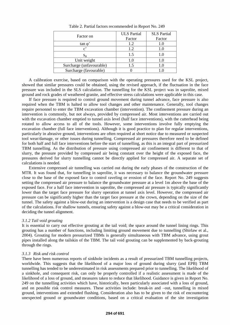
Table 2. Partial factors recommended in Report No. 249
Factor on ULS Partial Factor
SLS Partial Factor
tan φ’ 1.2 1.0 c’ 1.2 1.0 su 1.5 1.0
Unit weight 1.0 1.0 Surcharge (unfavourable) 1.5 1.0 Surcharge (favourable) 0 1.0
A calibration exercise, based on comparison with the operating pressures used for the KSL project,
showed that similar pressures could be obtained, using the revised approach, if the fluctuation in the face pressure was included in the SLS calculation. The tunnelling for the KSL project was in saprolite, mixed ground and rock grades of weathered granite, and effective stress calculations were applicable in this case.
If face pressure is required to control ground movement during tunnel advance, face pressure is also required when the TBM is halted to allow tool changes and other maintenance. Generally, tool changes require personnel to enter the TBM excavation chamber (intervention). The confinement pressure during an intervention is commonly, but not always, provided by compressed air. Most interventions are carried out with the excavation chamber emptied to tunnel axis level (half face interventions), with the cutterhead being rotated to allow access to all of the tools. However, some interventions involve fully emptying the excavation chamber (full face interventions). Although it is good practice to plan for regular interventions, particularly in abrasive ground, interventions are often required at short notice due to measured or suspected tool wear/damage, or other issues during tunnelling. Compressed air pressures therefore need to be defined for both half and full face interventions before the start of tunnelling, as this is an integral part of pressurized TBM tunnelling. As the distribution of pressure using compressed air confinement is different to that of slurry, the pressure provided by compressed air being constant over the height of the exposed face, the pressures derived for slurry tunnelling cannot be directly applied for compressed air. A separate set of calculations is needed.
Extensive compressed air tunnelling was carried out during the early phases of the construction of the MTR. It was found that, for tunnelling in saprolite, it was necessary to balance the groundwater pressure close to the base of the exposed face to control raveling or erosion of the face. Report No. 249 suggests setting the compressed air pressure to balance the groundwater pressure at a level 1m above the base of the exposed face. For a half face intervention in saprolite, the compressed air pressure is typically significantly lower than the target face pressure for slurry operation at tunnel axis level. However, the compressed air pressure can be significantly higher than the target face pressure at the crown, depending on the size of the tunnel. The safety against a blow-out during an intervention is a design case that needs to be verified as part of the calculations. For shallow tunnels, ensuring safety against a blow-out may be a critical consideration in deciding the tunnel alignment.
3.1.2 Tail void grouting It is essential to carry out effective grouting at the tail void; the space around the tunnel lining rings. This grouting has a number of functions, including limiting ground movement due to tunnelling (Shirlaw et al., 2004). Grouting for modern pressurized TBMs is generally simultaneous with TBM advance, using grout pipes installed along the tailskin of the TBM. The tail void grouting can be supplemented by back-grouting through the rings.
3.1.3 Risk and risk control There have been numerous reports of sinkhole incidents as a result of pressurized TBM tunnelling projects, worldwide. This suggests that the likelihood of a major loss of ground during slurry (and EPB) TBM tunnelling has tended to be underestimated in risk assessments prepared prior to tunnelling. The likelihood of a sinkhole, and consequent risk, can only be properly controlled if a realistic assessment is made of the likelihood of a loss of ground, and measures taken to reduce that likelihood. Guidance is given in Report No. 249 on the tunnelling activities which have, historically, been particularly associated with a loss of ground, and on possible risk control measures. These activities include: break-in and –out, tunnelling in mixed ground, interventions and extended flushing. Consideration also has to be given to the risk of encountering unexpected ground or groundwater conditions, based on a critical evaluation of the site investigation
294 of 691
information. It is now common practice in Hong Kong to have an emergency/contingency plan in place prior to the commencement of the tunnel drive.
3.1.4 Issues not covered or covered by reference Report No. 249 is intentionally focused on the calculations for the face pressures needed for slurry tunnelling, and on associated risk control measures. Issues that are not covered included:
• Detailed operation or arrangement of a slurry shield • Basis of selection of a slurry shield • Slurry preparation, cleaning or testing
These issues are covered elsewhere, and references are made in the report to selected documents.
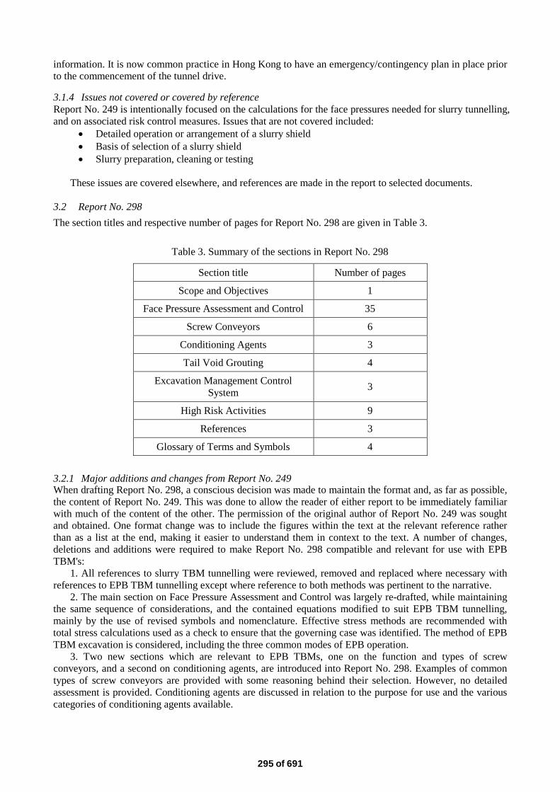
3.2 Report No. 298 The section titles and respective number of pages for Report No. 298 are given in Table 3.
Table 3. Summary of the sections in Report No. 298
Section title Number of pages
Scope and Objectives 1
Face Pressure Assessment and Control 35
Screw Conveyors 6
Conditioning Agents 3
Tail Void Grouting 4
Excavation Management Control System 3
High Risk Activities 9
References 3
Glossary of Terms and Symbols 4
3.2.1 Major additions and changes from Report No. 249 When drafting Report No. 298, a conscious decision was made to maintain the format and, as far as possible, the content of Report No. 249. This was done to allow the reader of either report to be immediately familiar with much of the content of the other. The permission of the original author of Report No. 249 was sought and obtained. One format change was to include the figures within the text at the relevant reference rather than as a list at the end, making it easier to understand them in context to the text. A number of changes, deletions and additions were required to make Report No. 298 compatible and relevant for use with EPB TBM's:
1. All references to slurry TBM tunnelling were reviewed, removed and replaced where necessary with references to EPB TBM tunnelling except where reference to both methods was pertinent to the narrative.
2. The main section on Face Pressure Assessment and Control was largely re-drafted, while maintaining the same sequence of considerations, and the contained equations modified to suit EPB TBM tunnelling, mainly by the use of revised symbols and nomenclature. Effective stress methods are recommended with total stress calculations used as a check to ensure that the governing case was identified. The method of EPB TBM excavation is considered, including the three common modes of EPB operation.
3. Two new sections which are relevant to EPB TBMs, one on the function and types of screw conveyors, and a second on conditioning agents, are introduced into Report No. 298. Examples of common types of screw conveyors are provided with some reasoning behind their selection. However, no detailed assessment is provided. Conditioning agents are discussed in relation to the purpose for use and the various categories of conditioning agents available.
295 of 691
3.2.2 Alternative operating modes The use of EPB TBM in Semi-Open mode, where compressed air is used in the upper half of the TBM excavation chamber is discussed. This mode of operation has been used on limited stretches of EPB TBM tunnelling in Hong Kong and Singapore, generally in mixed faces of rock and soil. However, there are significant risks and concerns over the use of this mode of operation, which are highlighted in the report.
The ongoing development of more complex variable density TBMs, which combine the advantages of both EPB and slurry TBMs, brings yet more variations in the area of confinement pressure assessment and control. As this new type of hybrid TBM was still in its early stage of development, it was not covered in either Report No. 249 or Report No. 298.
3.2.3 Conditioning agents Section 5 of Report No. 298 discusses the major types of conditioning agents currently available. They are broken down into four categories, viz. foaming agents, polymers, anti-clogging agents and anti-abrasion agents. Many of the products available on the market are designed to achieve a combination of these effects to achieve a suitable soil paste for EPB TBM operation, or to reduce the operating cost of the TBM. Foaming polymers are currently the most commonly used type of conditioning agents for EPB TBM tunnelling, providing a range of beneficial effects in commonly encountered ground conditions.
4. EXPERIENCE WITH REPORTS 249 AND 298
4.1 General A number of tunnel drives have been carried out in Hong Kong since Report No. 249 was issued. Many of these are either recently completed or still in progress, and a systematic review of the data has not been carried out. However, a summary of some of the relevant projects and the results of the tunnelling are presented below.
In this review, reference is made to the ‘overpressure’ applied during tunneling. Overpressure is the difference between the confinement pressure and the groundwater pressure, as discussed in Aristaghes and Autori (2003). The value of the overpressure provides a simple basis for comparing tunnels driven at different levels below ground and groundwater pressures. For slurry TBMs, the value of the overpressure is also a major factor in filter cake formation.
4.2 Slurry TBM Tunnelling for West Island Line Tsang, Salisbury and Yeung (2012) reported on the tunnelling for Contract C703 of the West Island line. There were two drives by the 6.35m diameter slurry TBM, with a total length of 1,260m. The drives were through Completely Decomposed Granite (CDG), mixed ground and rock, and passed under a number of high rise buildings. The target face pressures were initially calculated based on Report No. 249, and an SLS set at 1% volume loss, the default value for effective stress analysis in Report No. 249. Numerical analysis was carried out, with a target SLS for design of 1.5% volume loss. The numerical analysis indicated that higher confinement pressures were required to meet the SLS than found in the calculations using the simpler methods outlined in Report No. 249, despite the less stringent target for volume loss.
The overpressure applied at tunnel axis level was typically 0.1 bar in rock, 0.25 bar in CDG and mixed ground, but up to 0.7 bar when the tunnel was directly under the heavy loads imposed by the foundations of high rise buildings. Numerical analysis was particularly useful in assessing the effects of the buildings on the tunneling (and vice versa) and the interaction with an existing tunnel.
The reported actual volume loss was in the range of 0.24 to 0.44%, compared with the target value for design of 1.5%. Although 1.5% was set as the maximum target value for the tunnelling, a second check had been made to confirm that 3% volume loss would be acceptable in relation to the effect on buildings and utilities. Actual values of volume loss were therefore much lower than the highest value for which the buildings were assessed.
Based on the site investigation, the CDG encountered at tunnel level had an SPT-N value that was generally 100+, but locally about 50.
296 of 691
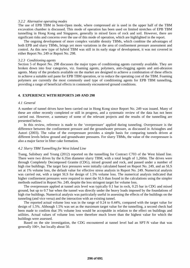
4.3 Slurry TBM Tunnelling for Guangzhou-Shenzhen-Hong Kong Express Rail Link (XRL), Contract 820, Mei Lai Road To Hoi Ting Road Tunnelling - Tunnel Sections from Tai Kok Tsui to Hoi Wang Road
The XRL is a cross boundary infrastructure project which will provide high speed rail connection between Guangzhou and Hong Kong. Four of the construction contracts involve soft and mixed ground tunneling: XRL 820, 823A, 825 and 826. XRL 823A and 825 have used EPB shields, while 820 and 826 have used slurry TBMs.
This sub-section will review data from XRL 820, Tai Kok Tsui to Hoi Wang Road. XRL820 comprises two sections of bored tunnels, driving north and south from the launching shaft at Nam Cheong. The route length of the tunnels is about 3.8km. The 9.33m diameter TBMs tunnels passed through saprolite, mixed ground, strong rock, with approximately 250m of alluvial and marine deposits. The tunnels were driven beneath two sensitive areas: Tai Kok Tsui and Hoi Wang Road, largely built in the 1960’s and 1990’s respectively, which were directly above or adjacent to the tunnels (Figures 3 and 4). Report No. 249 was adopted for assessing the required confinement pressures.
For granular soils, ULS analysis was carried out using the method based on Anagnostou and Kovari (1996), following section 3.2.1 of Report No. 249. For clayey soils, ULS analysis was carried out based on the results outlined in Kimura and Mair (1981). In order to assess the effects of the existing foundation loads and the adequacy of applied face pressures, and to properly control ground settlement and building movements, numerical analysis using a finite element computer program was also carried out to supplement Report No. 249. The target volume loss for the design was 1.0% to 2.0%, depending on the presence and nature of sensitive receivers.
Figure 3. One of the TBMs used for the XRL 820 tunnels, at the end of the drive
Figure 4. Jet grouting for a cross-passage and pile foundation protection along the running tunnels. Note the dense urban area with many high-rise buildings
The TBM drives were completed in September 2014, with face stability adequately maintained during
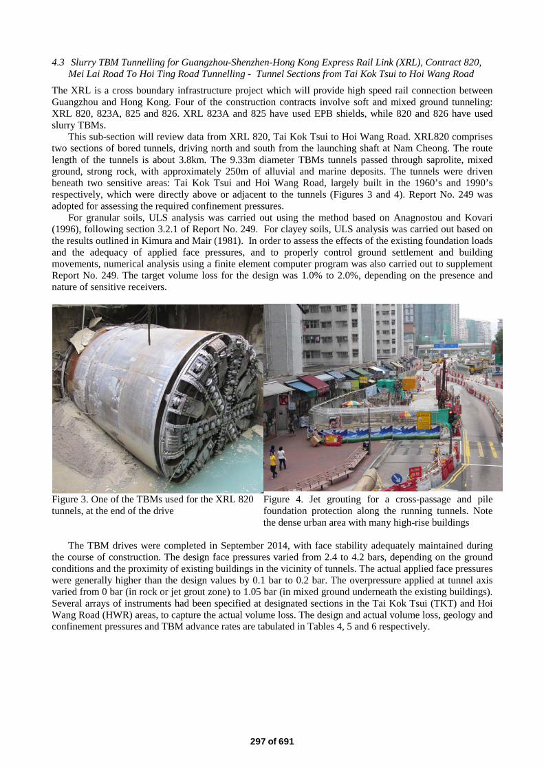
the course of construction. The design face pressures varied from 2.4 to 4.2 bars, depending on the ground conditions and the proximity of existing buildings in the vicinity of tunnels. The actual applied face pressures were generally higher than the design values by 0.1 bar to 0.2 bar. The overpressure applied at tunnel axis varied from 0 bar (in rock or jet grout zone) to 1.05 bar (in mixed ground underneath the existing buildings). Several arrays of instruments had been specified at designated sections in the Tai Kok Tsui (TKT) and Hoi Wang Road (HWR) areas, to capture the actual volume loss. The design and actual volume loss, geology and confinement pressures and TBM advance rates are tabulated in Tables 4, 5 and 6 respectively.
297 of 691
Table 4. Summary of Volume Loss and Settlement for XRL Project Contract 820
Table 5. Summary of Confinement Pressures
*Before grouting
Table 6. Average TBM Advance Rates
Cross Section/
Length (m) Area Design Volume
Loss (%)
Actual Volume Loss (settlement in mm)
(Downtrack Tunnel /Uptrack Tunnel)
Remarks
1 (20m) TKT 1.5 1.3(22) / 0.65(11) Trial section 2 (10m) TKT 1.5 1.0(17) / 0.18(3) Mixed ground 3 (20m) TKT 1.5 0.65(11) / 0.71(12) Stiffer soil (refer to Table 5 for
SPT ‘N’ values) 4 (50m) TKT 1.0 0.24(4) / 0.12(2) Rock 5 (20m) TKT 1.0 0.18(3) / 0.12(2) Rock 6 (60m) TKT 1.0 0.24(4) / 0.24(4) Rock 7 (10m) HWR 2.0 0.18(3) / 0.18(3) Local jet/TAM grout blocks 8 (40m) HWR 2.0 0.18(3) / 0.29(5) Local jet grout blocks 9 (60m) HWR 2.0 Heave (-5) / 0.18(3) Local jet grout blocks
10 (50m) HWR 1.0 Heave (-3) / 0.18(3) Jet grout zone
Tunnel Face Geology
Ground Cover
(m)
SPT ‘N’ at Tunnel Crown
Confinement Pressure/Hydrostatic Pressure at Tunnel Axis Level/ Overpressure (Bar)
Design (Downtrack)
Actual (Downtrack)
Design (Uptrack)
Actual (Uptrack)
CDG 30 45 4.0/3.2/0.8 4.1/3.2/0.9 4.0/3.2/ 0.8 4.0/3.2/0.8 Mixed
ground, CDG & Rock
30 55 4.1/3.4/0.7 4.35/3.3/1.05 4.1/3.4/0.7 4.1/3.3/0.8
CDG 30 96 3.9/3.45/0.45 4.1/3.5/0.6 4.2/3.45/0.75 4.2/3.4/0.8 Mixed
ground, CDG & Rock
30 >200 3.7/3.5/0.2 3.73/3.5/0.23 4.24/3.5/0.74 4.24/3.44/0.8
Rock 31 N/A 3.6/3.43/0.17 3.42/3.4/0.22 3.7/3.43/0.27 3.7/3.5/0.2 Rock 31 N/A 3.6/3.4/0.2 3.4/3.4/0 3.7/3.4/0.3 3.7/3.5/0.2 CDG 30 34* 3.5/3.1/0.4 3.5/2.8/0.7 3.5/3.1/0.4 3.5/3.2/0.3 CDG 27 32* 3.5/3.0/0.5 3.5/2.8/0.7 3.4/3.0/0.4 3.4/3.0/0.4 CDG
/Alluvium 25 18* 3.3/2.8/0.5 3.3/2.6/0.5 3.3/2.8/0.5 3.3/2.74/0.56
CDG/Alluvium (With
Jet Grouting) 21 12* 2.6/2.4/0.2 2.6/2.4/0.2 2.4/2.4/0 2.4/2.4/0
Cross Section
Average TBM Advance Rate (m/day) Downtrack Uptrack
1 16 16 2 4.5 4 3 13 9 4 8 9 5 11 9 6 9 7 7 16 30 8 28 34 9 22 25
10 10 15
298 of 691
The actual volume loss was generally significantly lower than the design target. However, the maximum measured volume loss, at 1.3%, was only a small margin lower than the design target value of 1.5%. If the design volume loss is treated as a ‘not to exceed’ value, then the result, overall, appears reasonable. Very low values of volume loss were recorded where the tunnel was in a full face of rock or a ground treatment zone. There also appears to be a general correlation between the SPT ‘N’ value of the CDG at tunnel crown and the measured volume loss, with a smaller value of volume loss in CDG with SPT>100, compared with the experience in SPT<100.
The presence of underground structures/facilities (piles foundation, utilities, etc.), may have also beneficially influenced the measured volume loss.
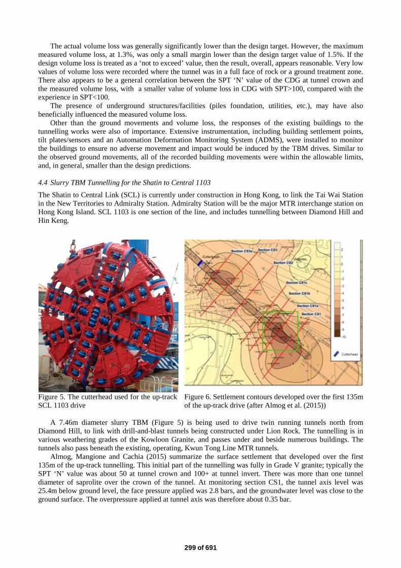
Other than the ground movements and volume loss, the responses of the existing buildings to the tunnelling works were also of importance. Extensive instrumentation, including building settlement points, tilt plates/sensors and an Automation Deformation Monitoring System (ADMS), were installed to monitor the buildings to ensure no adverse movement and impact would be induced by the TBM drives. Similar to the observed ground movements, all of the recorded building movements were within the allowable limits, and, in general, smaller than the design predictions. 4.4 Slurry TBM Tunnelling for the Shatin to Central 1103 The Shatin to Central Link (SCL) is currently under construction in Hong Kong, to link the Tai Wai Station in the New Territories to Admiralty Station. Admiralty Station will be the major MTR interchange station on Hong Kong Island. SCL 1103 is one section of the line, and includes tunnelling between Diamond Hill and Hin Keng.
Figure 5. The cutterhead used for the up-track SCL 1103 drive
Figure 6. Settlement contours developed over the first 135m of the up-track drive (after Almog et al. (2015))
A 7.46m diameter slurry TBM (Figure 5) is being used to drive twin running tunnels north from
Diamond Hill, to link with drill-and-blast tunnels being constructed under Lion Rock. The tunnelling is in various weathering grades of the Kowloon Granite, and passes under and beside numerous buildings. The tunnels also pass beneath the existing, operating, Kwun Tong Line MTR tunnels.
Almog, Mangione and Cachia (2015) summarize the surface settlement that developed over the first 135m of the up-track tunnelling. This initial part of the tunnelling was fully in Grade V granite; typically the SPT ‘N’ value was about 50 at tunnel crown and 100+ at tunnel invert. There was more than one tunnel diameter of saprolite over the crown of the tunnel. At monitoring section CS1, the tunnel axis level was 25.4m below ground level, the face pressure applied was 2.8 bars, and the groundwater level was close to the ground surface. The overpressure applied at tunnel axis was therefore about 0.35 bar.
299 of 691
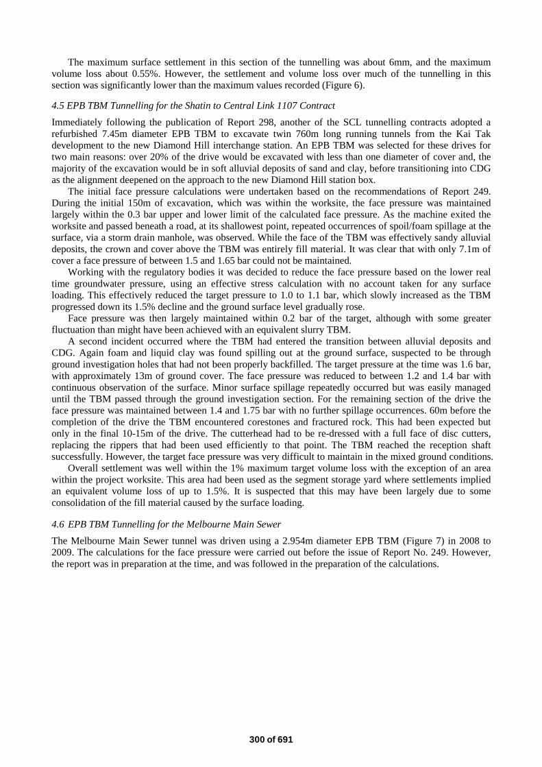
The maximum surface settlement in this section of the tunnelling was about 6mm, and the maximum volume loss about 0.55%. However, the settlement and volume loss over much of the tunnelling in this section was significantly lower than the maximum values recorded (Figure 6). 4.5 EPB TBM Tunnelling for the Shatin to Central Link 1107 Contract Immediately following the publication of Report 298, another of the SCL tunnelling contracts adopted a refurbished 7.45m diameter EPB TBM to excavate twin 760m long running tunnels from the Kai Tak development to the new Diamond Hill interchange station. An EPB TBM was selected for these drives for two main reasons: over 20% of the drive would be excavated with less than one diameter of cover and, the majority of the excavation would be in soft alluvial deposits of sand and clay, before transitioning into CDG as the alignment deepened on the approach to the new Diamond Hill station box.
The initial face pressure calculations were undertaken based on the recommendations of Report 249. During the initial 150m of excavation, which was within the worksite, the face pressure was maintained largely within the 0.3 bar upper and lower limit of the calculated face pressure. As the machine exited the worksite and passed beneath a road, at its shallowest point, repeated occurrences of spoil/foam spillage at the surface, via a storm drain manhole, was observed. While the face of the TBM was effectively sandy alluvial deposits, the crown and cover above the TBM was entirely fill material. It was clear that with only 7.1m of cover a face pressure of between 1.5 and 1.65 bar could not be maintained.
Working with the regulatory bodies it was decided to reduce the face pressure based on the lower real time groundwater pressure, using an effective stress calculation with no account taken for any surface loading. This effectively reduced the target pressure to 1.0 to 1.1 bar, which slowly increased as the TBM progressed down its 1.5% decline and the ground surface level gradually rose.
Face pressure was then largely maintained within 0.2 bar of the target, although with some greater fluctuation than might have been achieved with an equivalent slurry TBM.
A second incident occurred where the TBM had entered the transition between alluvial deposits and CDG. Again foam and liquid clay was found spilling out at the ground surface, suspected to be through ground investigation holes that had not been properly backfilled. The target pressure at the time was 1.6 bar, with approximately 13m of ground cover. The face pressure was reduced to between 1.2 and 1.4 bar with continuous observation of the surface. Minor surface spillage repeatedly occurred but was easily managed until the TBM passed through the ground investigation section. For the remaining section of the drive the face pressure was maintained between 1.4 and 1.75 bar with no further spillage occurrences. 60m before the completion of the drive the TBM encountered corestones and fractured rock. This had been expected but only in the final 10-15m of the drive. The cutterhead had to be re-dressed with a full face of disc cutters, replacing the rippers that had been used efficiently to that point. The TBM reached the reception shaft successfully. However, the target face pressure was very difficult to maintain in the mixed ground conditions.
Overall settlement was well within the 1% maximum target volume loss with the exception of an area within the project worksite. This area had been used as the segment storage yard where settlements implied an equivalent volume loss of up to 1.5%. It is suspected that this may have been largely due to some consolidation of the fill material caused by the surface loading.
4.6 EPB TBM Tunnelling for the Melbourne Main Sewer The Melbourne Main Sewer tunnel was driven using a 2.954m diameter EPB TBM (Figure 7) in 2008 to 2009. The calculations for the face pressure were carried out before the issue of Report No. 249. However, the report was in preparation at the time, and was followed in the preparation of the calculations.
300 of 691
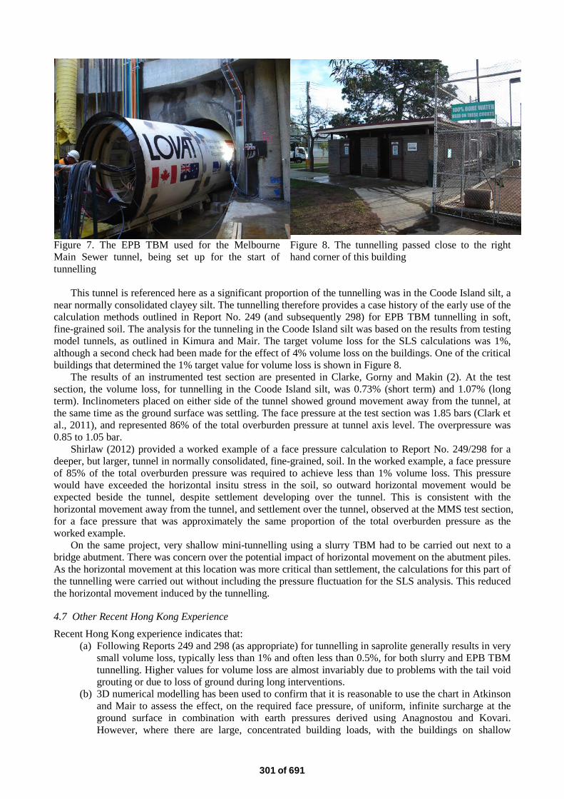
Figure 7. The EPB TBM used for the Melbourne Main Sewer tunnel, being set up for the start of tunnelling
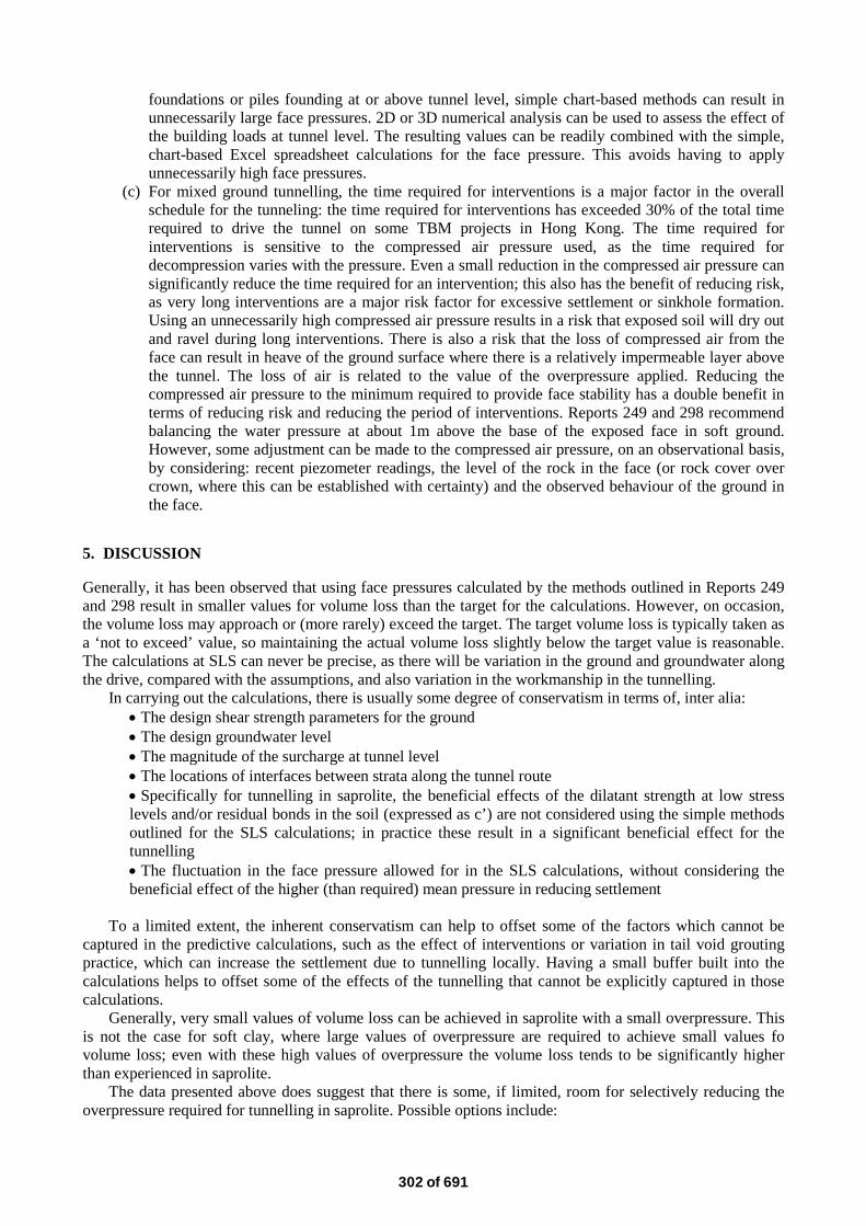
Figure 8. The tunnelling passed close to the right hand corner of this building
This tunnel is referenced here as a significant proportion of the tunnelling was in the Coode Island silt, a
near normally consolidated clayey silt. The tunnelling therefore provides a case history of the early use of the calculation methods outlined in Report No. 249 (and subsequently 298) for EPB TBM tunnelling in soft, fine-grained soil. The analysis for the tunneling in the Coode Island silt was based on the results from testing model tunnels, as outlined in Kimura and Mair. The target volume loss for the SLS calculations was 1%, although a second check had been made for the effect of 4% volume loss on the buildings. One of the critical buildings that determined the 1% target value for volume loss is shown in Figure 8.
The results of an instrumented test section are presented in Clarke, Gorny and Makin (2). At the test section, the volume loss, for tunnelling in the Coode Island silt, was 0.73% (short term) and 1.07% (long term). Inclinometers placed on either side of the tunnel showed ground movement away from the tunnel, at the same time as the ground surface was settling. The face pressure at the test section was 1.85 bars (Clark et al., 2011), and represented 86% of the total overburden pressure at tunnel axis level. The overpressure was 0.85 to 1.05 bar.
Shirlaw (2012) provided a worked example of a face pressure calculation to Report No. 249/298 for a deeper, but larger, tunnel in normally consolidated, fine-grained, soil. In the worked example, a face pressure of 85% of the total overburden pressure was required to achieve less than 1% volume loss. This pressure would have exceeded the horizontal insitu stress in the soil, so outward horizontal movement would be expected beside the tunnel, despite settlement developing over the tunnel. This is consistent with the horizontal movement away from the tunnel, and settlement over the tunnel, observed at the MMS test section, for a face pressure that was approximately the same proportion of the total overburden pressure as the worked example.
On the same project, very shallow mini-tunnelling using a slurry TBM had to be carried out next to a bridge abutment. There was concern over the potential impact of horizontal movement on the abutment piles. As the horizontal movement at this location was more critical than settlement, the calculations for this part of the tunnelling were carried out without including the pressure fluctuation for the SLS analysis. This reduced the horizontal movement induced by the tunnelling.
4.7 Other Recent Hong Kong Experience Recent Hong Kong experience indicates that:
(a) Following Reports 249 and 298 (as appropriate) for tunnelling in saprolite generally results in very small volume loss, typically less than 1% and often less than 0.5%, for both slurry and EPB TBM tunnelling. Higher values for volume loss are almost invariably due to problems with the tail void grouting or due to loss of ground during long interventions.
(b) 3D numerical modelling has been used to confirm that it is reasonable to use the chart in Atkinson and Mair to assess the effect, on the required face pressure, of uniform, infinite surcharge at the ground surface in combination with earth pressures derived using Anagnostou and Kovari. However, where there are large, concentrated building loads, with the buildings on shallow
301 of 691
foundations or piles founding at or above tunnel level, simple chart-based methods can result in unnecessarily large face pressures. 2D or 3D numerical analysis can be used to assess the effect of the building loads at tunnel level. The resulting values can be readily combined with the simple, chart-based Excel spreadsheet calculations for the face pressure. This avoids having to apply unnecessarily high face pressures.
(c) For mixed ground tunnelling, the time required for interventions is a major factor in the overall schedule for the tunneling: the time required for interventions has exceeded 30% of the total time required to drive the tunnel on some TBM projects in Hong Kong. The time required for interventions is sensitive to the compressed air pressure used, as the time required for decompression varies with the pressure. Even a small reduction in the compressed air pressure can significantly reduce the time required for an intervention; this also has the benefit of reducing risk, as very long interventions are a major risk factor for excessive settlement or sinkhole formation. Using an unnecessarily high compressed air pressure results in a risk that exposed soil will dry out and ravel during long interventions. There is also a risk that the loss of compressed air from the face can result in heave of the ground surface where there is a relatively impermeable layer above the tunnel. The loss of air is related to the value of the overpressure applied. Reducing the compressed air pressure to the minimum required to provide face stability has a double benefit in terms of reducing risk and reducing the period of interventions. Reports 249 and 298 recommend balancing the water pressure at about 1m above the base of the exposed face in soft ground. However, some adjustment can be made to the compressed air pressure, on an observational basis, by considering: recent piezometer readings, the level of the rock in the face (or rock cover over crown, where this can be established with certainty) and the observed behaviour of the ground in the face.
5. DISCUSSION
Generally, it has been observed that using face pressures calculated by the methods outlined in Reports 249 and 298 result in smaller values for volume loss than the target for the calculations. However, on occasion, the volume loss may approach or (more rarely) exceed the target. The target volume loss is typically taken as a ‘not to exceed’ value, so maintaining the actual volume loss slightly below the target value is reasonable. The calculations at SLS can never be precise, as there will be variation in the ground and groundwater along the drive, compared with the assumptions, and also variation in the workmanship in the tunnelling.
In carrying out the calculations, there is usually some degree of conservatism in terms of, inter alia: • The design shear strength parameters for the ground • The design groundwater level • The magnitude of the surcharge at tunnel level • The locations of interfaces between strata along the tunnel route • Specifically for tunnelling in saprolite, the beneficial effects of the dilatant strength at low stress levels and/or residual bonds in the soil (expressed as c’) are not considered using the simple methods outlined for the SLS calculations; in practice these result in a significant beneficial effect for the tunnelling • The fluctuation in the face pressure allowed for in the SLS calculations, without considering the beneficial effect of the higher (than required) mean pressure in reducing settlement
To a limited extent, the inherent conservatism can help to offset some of the factors which cannot be
captured in the predictive calculations, such as the effect of interventions or variation in tail void grouting practice, which can increase the settlement due to tunnelling locally. Having a small buffer built into the calculations helps to offset some of the effects of the tunnelling that cannot be explicitly captured in those calculations.
Generally, very small values of volume loss can be achieved in saprolite with a small overpressure. This is not the case for soft clay, where large values of overpressure are required to achieve small values fo volume loss; even with these high values of overpressure the volume loss tends to be significantly higher than experienced in saprolite.
The data presented above does suggest that there is some, if limited, room for selectively reducing the overpressure required for tunnelling in saprolite. Possible options include:
302 of 691
(a) Leaving the term to allow for the fluctuation in the face pressure in the ULS calculations, but
excluding the term from the SLS calculations. (b) Instead of setting a target face pressure, set minimum and maximum values for face pressure; this
would leave some flexibility for the tunnel team to adjust where they set the pressure within these boundaries. The minimum in this case would be an absolute minimum against excessive ground settlement for that location: the pressure that the actual pressure should not fall below at any time
(c) Reassessing the concept of, and the response to, the target volume loss. Typically, the target value has been used in the design to assess the potential impact on buildings and utilities, but a second set of calculations carried out at a higher value to confirm that the higher value would still be acceptable. Thus, if the design value is 1% volume loss, a check may be made for 2% volume loss. If the value of 1% volume loss is then treated as a ‘do not exceed’ value, a double level of conservatism is introduced. One way to overcome this might be to treat the value for volume loss in the same way that other instrumentation data is reviewed. For the example values given, using the ‘traffic light’ system, up to 1% volume loss would be green (no action required), 1 to 1.5% would be amber (watch more closely) and over 1.5% red (take action to reduce).
(d) Specifically for saprolite, develop methods to take account in the SLS analysis of the effective cohesion present. Currently, this can be considered in numerical analysis, but not in the simpler spreadsheet methods that form the basis for the GEO guidance documents. Parametric studies, justified by empirical data, may allow a simple, chart-based adjustment to the current methods, rather than embarking on extensive numerical analyses for every tunnel drive.
(e) Based on the examples given above, there appears to be a significant difference between tunnelling in CDG with an SPT ‘N’ value <100, for which volume loss values are typically only slightly smaller than target values, and CDG with N >100, for which the volume loss values are much smaller, for the same value of overpressure. A more comprehensive assessment of the field data than has been carried out in this paper should allow for some refinement of the current basis for SLS calculations in saprolite.
(f) As water pressure is a very large proportion of the total face pressure required in coarse-grained soils, including many saprolites in Hong Kong, refining the design water pressure can significantly reduce the conservatism in the input parameters. If there are only a few piezometers, widely spaced, along the tunnel drive, then the design water pressure that has to be adopted is necessarily conservative. More piezometers, and more detailed assessment of the data from those piezometers, should allow fine tuning of this key input parameter. In critical locations, as in the example given above for SCL 1107, adjusting the target pressure based on real time monitoring information is a viable method of minimizing the target pressure.
The first item above would be a change to Reports 249 and 298. The remaining suggestions would not
require modification of the reports, but could modify the way in which they are applied.
6. CONCLUSIONS
GEO Reports 249 and 298 have provided a basis for face pressure calculations for slurry and EPB TBM tunnelling respectively. This paper has provided a limited review of some of the experience of working to the reports, and of the degree of ground control achieved on selected projects.
For tunnelling in saprolite, it appears that the calculation methods outlined in the reports are probably slightly conservative. This conservatism is likely to be mainly due to conservatism in the derivation of the design soil parameters and groundwater pressures. Where the tunnel is in saprolite, with an adequate cover of saprolite, small values for overpressure in the range of 0.25 to 0.4 bar generally result in very small settlement and volume loss. A small reduction in the overpressure used for tunnelling in saprolite appears to be justifiable.
Tunnelling in the dense urban areas of Hong Kong involves tunnelling under and near tall buildings, frequently over 30 storeys. The loads imposed on the ground by such buildings can be very large. It is worthwhile to carry out detailed numerical analysis of the effects of the buildings on the confinement pressure required at the face of the TBM, to avoid applying unnecessarily large pressures.
Good control of ground movements can be achieved even in soft clay, using pressures calculated by the methods outlined in the reports. However, the face pressures required to achieve very small values for
303 of 691
volume loss in normally consolidated clay are high, as a proportion of the total overburden pressure. At this level of face pressure, the clay can be displaced away from the tunnel horizontally, at the same time as the ground over the tunnel is settling. Depending on whether vertical or horizontal ground movements are critical, some adjustment to the confinement pressures may be necessary to minimize the impact of the tunnelling.
One possible modification to the reports is to exclude the term for the fluctuation in pressure from the SLS analysis. However, given the very small values for overpressure that result from calculations based on the current reports, the scope and practical effect the reduction that can be achieved for TBM driving is limited. It is suggested that there is greater scope for economy and tunnel advance rate improvement, without compromising safety, in refining the assessment of the design groundwater pressure and the compressed air pressure required for interventions.
Both reports should be used with due caution when considering areas of low overburden, i.e. less than 1.5 diameters of cover, where the cover is largely fill material or where large buried structures such as storm drains or manholes are encountered.
ACKNOWLEDGEMENTS
This paper is published with the permission of the Director of Civil Engineering and Development and the Head of the Geotechnical Engineering Office of the CEDD, HKSARG. The authors thank the Mass Transit Railway Corporation Limited for permission to use the data from their projects. The assistance of Ir Ivan Chan of GEO in collecting information on the XRL project and in reviewing the paper is also acknowledged. REFERENCES
Almog, E., Mangione, M. and Cachia, G. (2015). Ground relaxation in segmental lining design using the Convergence-Confinement Method. In press.
Anagnostu, G. & Kovari, K. (1996). Face stability in slurry and EPB shield tunnelling. Proceedings of the Symposium on Geotechnical Aspects of Underground Construction in Soft Ground, London, 379-384.
Aristaghes, P. and Autuori, P. (2003). Confinement efficiency concept in soft ground bored tunnels. Proceedings of World Tunnelling Congress, (Re) Claiming the Underground Space, Vol 2, Ed. J. Saveur, publ. A.A. Balkema, pp909-914
Atkinson, J.H. and Mair, R.J. (1981). Soil mechanics aspects of soft ground tunnelling. Ground Engineering, July, 20-26.
BTS/ICE. (2005). Closed-face Tunnelling Machines and Ground Stability: A Guideline for Best Practice. British Tunnelling Society with the Institution of Civil Engineers, Thomas Telford, 77 p.
Broere, W. (1998). Face stability calculation for a slurry shield in heterogeneous soft soils. Tunnels and Metropolises, Sao Paulo, Brazil, 215-218.
Broere, W. (2001). Tunnel Face Stability & New CPT Applications. PhD Thesis, Technical University of Delft.
Broere, W. (2005). Influence of excess pore pressures on the stability of the tunnel face. (Re)Claiming the Underground Space, ITA, Amsterdam, 2003, 759-765.
Clark, P., Gorny, A. and Makin, N. (2011). Melbourne Main Sewer Project – Construction Phase – Soft ground tunnelling in the Yarra Delta. Proceedings of the 14th Australasian Tunnelling Conference, Auckland, New Zealand, March 2011, 69-81.
Jancsecz, S. and Steiner, W. (1994). Face support for a large Mixshield in heterogeneous ground conditions. Tunnelling 94, London, The Institution of Mining and Metallurgy.
Haswell, C.K., Umney, A.R., Hall, P., Hansen, F.J., Storey, F.G., Archer, G.O. and Langfield, R.A. (1980). Hong Kong Mass Transit Railway Modified Initial System: Design and construction of the driven tunnels and the immersed tube. Proceedings of the Institution of Civil Engineers, vol. 68: 627-655. (Discussion, vol. 72, 1982: 87-98).
Kimura, T. and Mair, R.J. (1981). Centrifugal testing of model tunnels in soft clay. Proceedings of the 10th International Conference on Soil Mechanics and Foundation Engineering, Stockholm, 1: 319-322.
304 of 691
Pang, P.L.R. (2011). Geotechnical control and risk management of tunnel projects in Hong Kong. Invited Special Lecture. Proceedings of the International Conference on Tunnelling and Trenchless Technology, Kuala Lumpur, Malaysia, 41-51.
Pang, P.L.R. (2014). Geotechnical control of tunnel works in Hong Kong. Proceedings of the Institution of Civil Engineers: Forensic Engineering. http://dx.doi.org/10.1680/feng.13.00025.
Proctor, R.V. and White, T.L. (1977). Earth Tunnelling with Steel Supports. Commercial Shearing and Stamping Co, Youngstown, Ohio.
Shirlaw, J.N., Ong, J.C.W. Rosser, H.B., Tan, C.G, Osborne, N.H. and Heslop P.J.E. (2003). Local settlements and sinkholes due to EPB tunnelling. Geotechnical Engineering, 156(4): 193 – 211.
Shirlaw, J.N., Richards, D.P., Raymond, P. and Longchamp, P. (2004). Recent experience in automatic tail void grouting with soft ground tunnel boring machines. Proceedings of the 30th ITA-AITES World Tunnel Congress, Singapore, Ed. J.N. Shirlaw, J. Zhao and R. Krishnan. Tunnelling and Underground Space Technology July-September 2004, 19(4-5).
Shirlaw, J.N. (2012). Setting operating pressures for TBM tunnelling. Keynote lecture, HKIE Geotechnical Division, 32nd Annual Seminar, Geotechnical Aspects of Tunnelling for Infrastructure Development, May 2012, Hong Kong, 7-28.
Surjadamata, O’Shannessy and Hull, T. (2011). Measurement of tunnelling induced soil movement in Coode Island Silt. Proceedings of the International Conference on Advances in Geotechnical Engineering, Perth, Australia, Nov 7-9, 2011.
Tsang, A.C.M., Salisbury, C.D. and Yeung, S.S.M. (2012). Confinement pressure for face stability of tunnel boring machine (TBM) excavation under Hong Kong’s Western District. HKIE Geotechnical Division, 32nd Annual Seminar, Geotechnical Aspects of Tunnelling for Infrastructure Development, May 2012, Hong Kong, pp147-158.
305 of 691
View publication statsView publication stats


![TBM 렌탈솔루션 - cafe24mrrental.cafe24.com/tbm/tbmrs_service_introduction.pdf · 01. TBM 렌탈솔루션소개 [이미지출처: 효성에프엠에스뉴스레터(2019.01.28)]](https://img.pdfslide.net/doc/110x75/5ece13d36c14a753b559968e/tbm-eoefe-01-tbm-eoefeoeeoe-eoe-ee20190128.jpg)