Embed Size (px)
Citation preview

The development of the NIMISiS The development of the NIMISiS Bias Control GUIBias Control GUIby Christopher Crane by Christopher Crane
Mentor Dr. Sherry YennelloMentor Dr. Sherry Yennello
OutlineOutline
Overview of intermediate energy physicsOverview of intermediate energy physics
Why use NIMROD?Why use NIMROD?
NIMROD upgradeNIMROD upgrade
What is a silicon detector and a photodiode What is a silicon detector and a photodiode detector?detector?
What is a bias box?What is a bias box?
Previous methods of setting channels and Previous methods of setting channels and why use a graphical user interface?why use a graphical user interface?
Connecting NIMROD and SummaryConnecting NIMROD and Summary
A
ZNa
A
ZAAaAaMevE symcsvB
2
31
23
2 )()(
Intermediate Energy PhysicsIntermediate Energy Physics
Different kinds of particles and the necessity for Different kinds of particles and the necessity for different kinds of particle detectorsdifferent kinds of particle detectors
From fragment yields at intermediate energies From fragment yields at intermediate energies From isobaric ratios From isobaric ratios
We can learn about temperature We can learn about temperature
The asymmetry term in the equation of state*The asymmetry term in the equation of state*
Get isotopic distributions Get isotopic distributions Phase transitionPhase transition
Why Use NIMROD?Why Use NIMROD?
NIMROD consists of telescopes and super NIMROD consists of telescopes and super telescopes.telescopes. A telescope consists of a gas detector, a silicon detector, A telescope consists of a gas detector, a silicon detector,
and a cesium iodide detector. and a cesium iodide detector. A super telescope consists of a gas detector, two silicon A super telescope consists of a gas detector, two silicon
detectors, and a cesium iodide detectordetectors, and a cesium iodide detector. .
These are arranged in a 4These are arranged in a 4ππ or spherical or spherical arrangement.arrangement.
This is good for central, intermediate energy This is good for central, intermediate energy collisions. It is also efficient at detecting heavy collisions. It is also efficient at detecting heavy residues.residues.
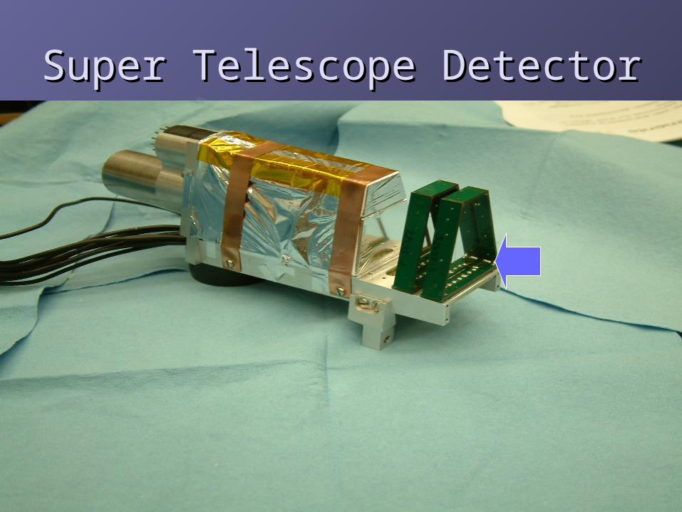
Super Telescope DetectorSuper Telescope Detector
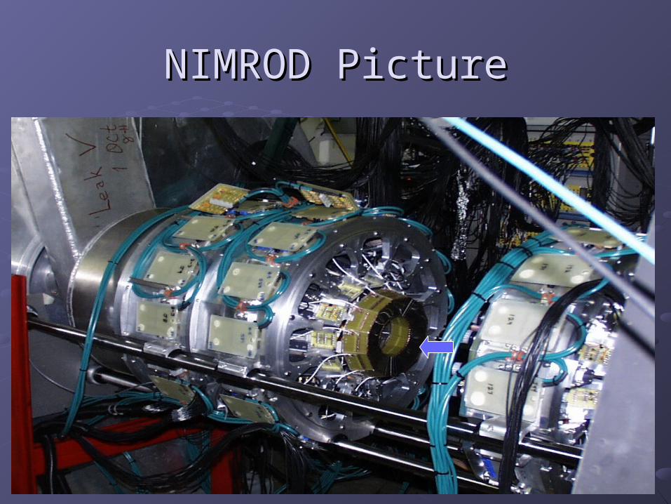
NIMROD PictureNIMROD Picture
Upgrade of NIMROD Upgrade of NIMROD
Additional silicon detectors are being Additional silicon detectors are being added in the forward beam direction to added in the forward beam direction to NIMRODNIMRODThe addition consists of an additional ring The addition consists of an additional ring from 45 to 90 degrees and a half sphere from 45 to 90 degrees and a half sphere from the ISiS array.from the ISiS array.The ISiS array also consists of telescopes The ISiS array also consists of telescopes (gas detector, silicon detector, and cesium (gas detector, silicon detector, and cesium iodide detector)iodide detector)
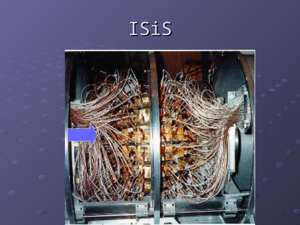
ISiSISiS
Silicon DetectorsSilicon Detectors
Silicon detectors are a PN junction.Silicon detectors are a PN junction.The detectors need an electrical voltage to The detectors need an electrical voltage to be applied in order to create a layer of be applied in order to create a layer of depletion at the junction. depletion at the junction. Why depletion is important?Why depletion is important?What is leakage current?What is leakage current?As Radiation bombards these silicon As Radiation bombards these silicon detectors it becomes harder and harder to detectors it becomes harder and harder to maintain the depletion layer. maintain the depletion layer.
Photodiode DetectorPhotodiode Detector
A silicon wafer that is used to capture light A silicon wafer that is used to capture light signals produced by radiation in cesium signals produced by radiation in cesium iodide detectorsiodide detectors
This are used to collect the signals from This are used to collect the signals from the cesium iodide detectors of ISiS the cesium iodide detectors of ISiS
What is a Bias Box?What is a Bias Box?
Delivers positive or negative voltage.Delivers positive or negative voltage.
between 0-255 voltsbetween 0-255 volts
It can control up to 320 channels at one It can control up to 320 channels at one timetime
Can monitor leakage current and actual Can monitor leakage current and actual voltage on a silicon or photodiode type voltage on a silicon or photodiode type detectordetector
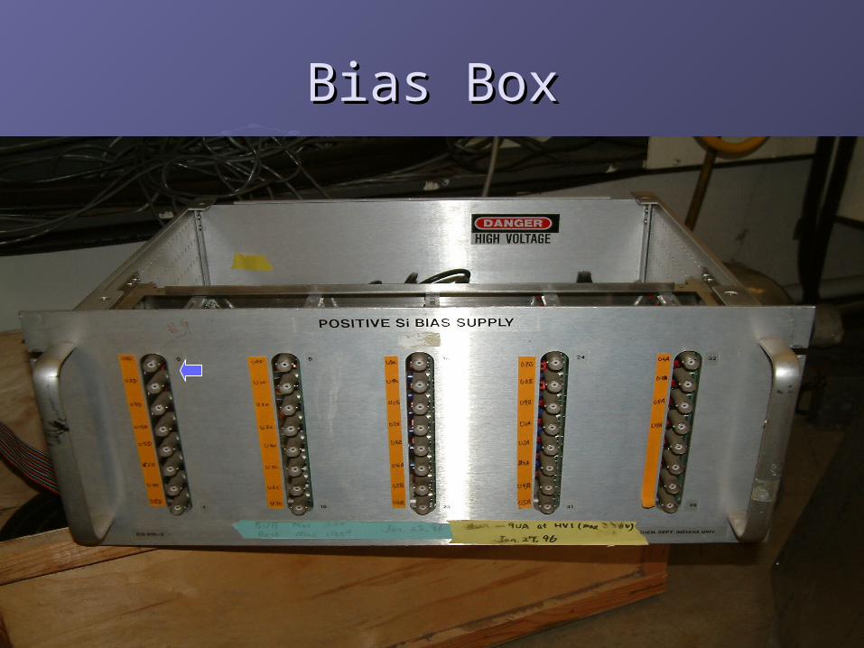
Bias BoxBias Box
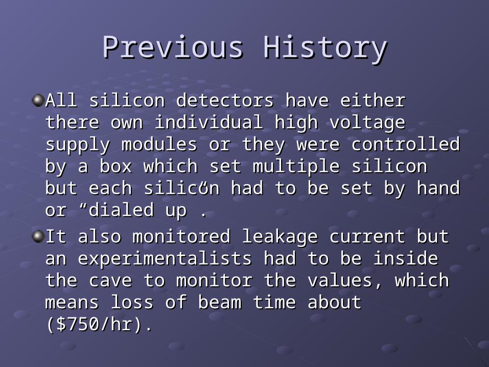
Previous HistoryPrevious History
All silicon detectors have either there own All silicon detectors have either there own individual high voltage supply modules or individual high voltage supply modules or they were controlled by a box which set they were controlled by a box which set multiple silicon but each silicon had to be multiple silicon but each silicon had to be set by hand or “dialed up”. set by hand or “dialed up”.
It also monitored leakage current but an It also monitored leakage current but an experimentalists had to be inside the cave experimentalists had to be inside the cave to monitor the values, which means loss of to monitor the values, which means loss of beam time about ($750/hr).beam time about ($750/hr).
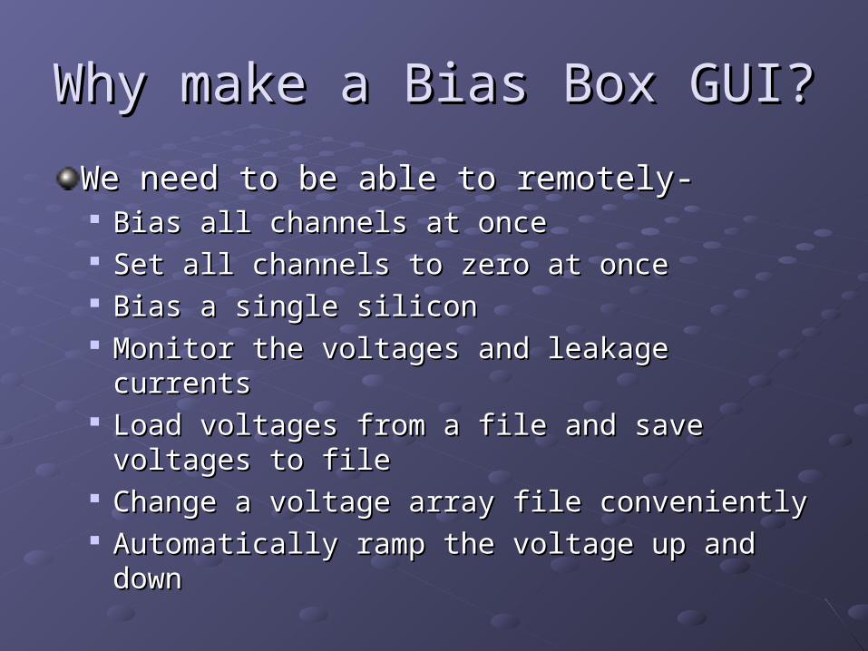
Why make a Bias Box GUI?Why make a Bias Box GUI?
We need to be able to remotely-We need to be able to remotely- Bias all channels at onceBias all channels at once Set all channels to zero at onceSet all channels to zero at once Bias a single siliconBias a single silicon Monitor the voltages and leakage currentsMonitor the voltages and leakage currents Load voltages from a file and save voltages to Load voltages from a file and save voltages to
filefile Change a voltage array file convenientlyChange a voltage array file conveniently Automatically ramp the voltage up and downAutomatically ramp the voltage up and down
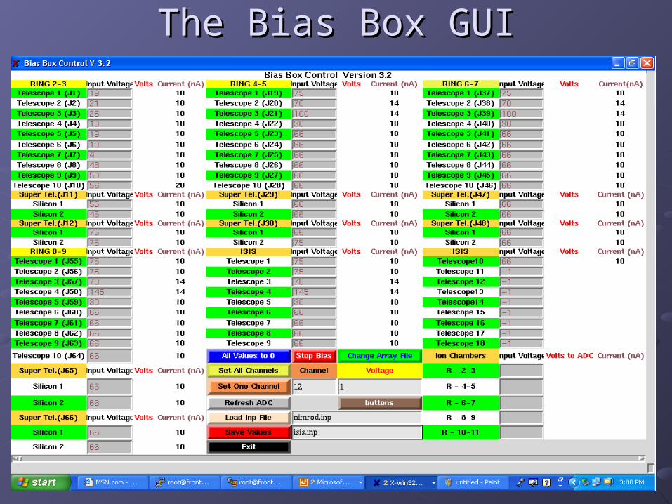
The Bias Box GUIThe Bias Box GUI
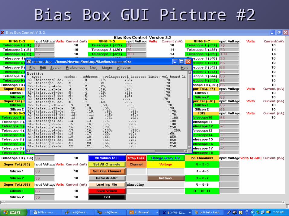
Bias Box GUI Picture #2Bias Box GUI Picture #2
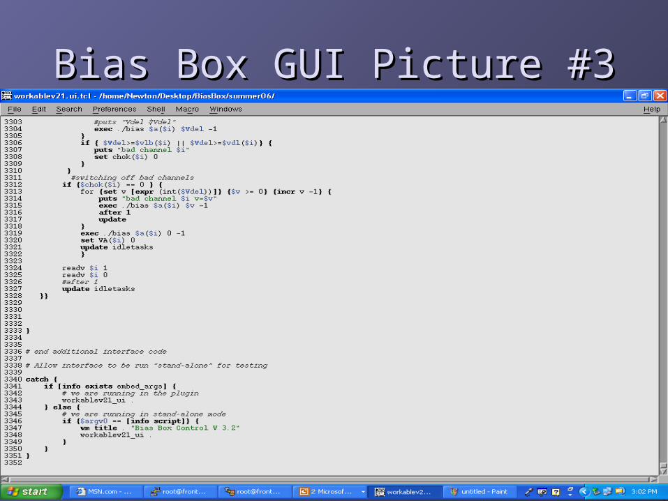
Bias Box GUI Picture #3Bias Box GUI Picture #3
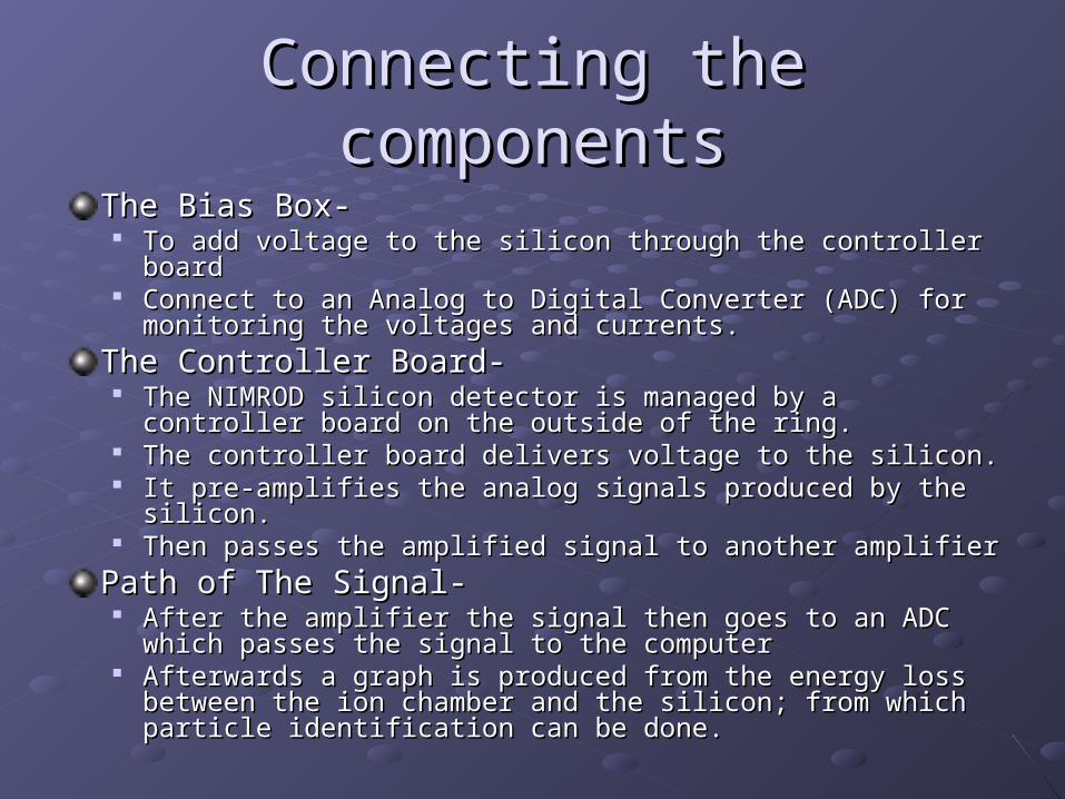
Connecting the componentsConnecting the components
The Bias Box-The Bias Box- To add voltage to the silicon through the controller boardTo add voltage to the silicon through the controller board Connect to an Analog to Digital Converter (ADC) for monitoring Connect to an Analog to Digital Converter (ADC) for monitoring
the voltages and currents.the voltages and currents.
The Controller Board-The Controller Board- The NIMROD silicon detector is managed by a controller board The NIMROD silicon detector is managed by a controller board
on the outside of the ring.on the outside of the ring. The controller board delivers voltage to the silicon.The controller board delivers voltage to the silicon. It pre-amplifies the analog signals produced by the silicon.It pre-amplifies the analog signals produced by the silicon. Then passes the amplified signal to another amplifierThen passes the amplified signal to another amplifier
Path of The Signal-Path of The Signal- After the amplifier the signal then goes to an ADC which passes After the amplifier the signal then goes to an ADC which passes
the signal to the computer the signal to the computer Afterwards a graph is produced from the energy loss between Afterwards a graph is produced from the energy loss between
the ion chamber and the silicon; from which particle identification the ion chamber and the silicon; from which particle identification can be done.can be done.
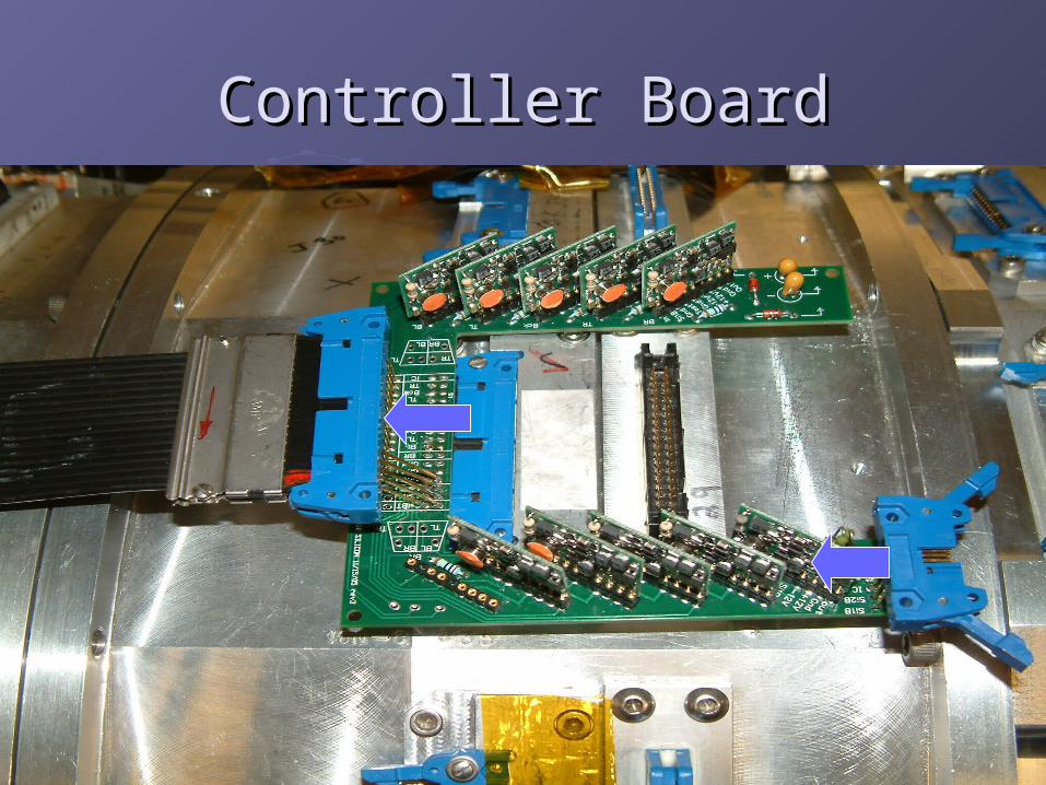
Controller BoardController Board
SummarySummary
User Interface program was designed with the intent of monitoring voltage and current while biasing to NIMROD’s detectors remotely, including the new addition of ISiS, a spherical particle detector.
The program takes user input values and sends Biasing voltages to NIMROD’s silicon detectors. The GUI also monitors the actual charge held in the detectors of a specified silicon, and the leakage current on a specific silicon.
Acknowledgements
The National Science Foundation
The Department of Energy
SJY Group- Dr. Sherry Yennello, Sara Wuenschel, August
Keksis, Zach Kohley, Brian Stein, Sarah Soisson, George Souliotis, and Dinesh Shetty.
Thank You for your attentionThank You for your attention
Thank You REU Program at Texas A & M Thank You REU Program at Texas A & M UniversityUniversity