Embed Size (px)
Citation preview
© 2000, Red Hot Radio, © 2012, Hendricks QRP Kits – Unauthorized Copying or Publication Prohibited
1
The Hendricks QRP Kits SMK-2 Construction Manual
A Learning Tool For
Surface Mount Construction Kit Building
By Dave Fifield, AD6A Revision 1.9 April 2012
WARNING – DO NOT OPEN ANY OF THE PARTS BAGS YET!
If you really must skip the introduction - be sure and read the section titled “Don’t Open the Parts Bags Yet” at the top of page 3 BEFORE you start!
© 2000, Red Hot Radio, © 2012, Hendricks QRP Kits – Unauthorized Copying or Publication Prohibited
2
The SMK-2 Construction Manual
Introduction
Thank you for buying a Hendricks QRP Kits SMK-2 kit. We’re sure you will enjoy learning/practicing surface mount construction techniques by building the SMK-2. As a bonus, when built, the SMK-2 is a fully working 40m CW transceiver that you will be able to use on the air to make contacts! The idea to produce the SMK-2 kit came from Doug Hendricks, KI6DS, who thought it would be a good idea to have a cheap learning tool to get hams used to doing surface mount construction, since that’s the way virtually the whole electronic industry has gone and will inevitably become the technique of necessity for ham kits in the future. It was first kitted by the NorCal QRP Club known as the SMK-1. It was a board only kit at that time. Red Hot Radio was purchased by Hendricks QRP Kits in December 2011, and the decision was made to update the SMK-1 by adding a case and making a small circuit change to improve the performance. The updated kit also uses two 3 pin female SIP strips as crystal sockets. This will allow crystals to be changed easily. The Hendricks QRP Kit will ship with both 7.030 and 7.040 crystals, hence the name SMK-2. Everything you will need to turn the SMK-2 into a fully working rig is included in the kit. The custom case was designed by Ken LoCasale, WA4MNT, and is an addition to the original SMK-1 kit. The SMK-2 contains over 80 components. Most of them are surface mount parts. Some parts, like crystals, trim caps and pots, are either too expensive or not easily obtained in surface mount packages, so through hole parts are used. The surface mount parts used in the SMK-2 were chosen to be large enough for most hams to be able to handle them with a small pair of tweezers and solder them in place using a fine-tip soldering iron. They are not the smallest surface mount parts by a long way, but they are small. I have personally built several kits now without using a magnifier, but I do recommend you use one if you have one! It will make life a lot easier for you, especially if your eyesight isn’t quite what it used to be! I recommend that you use a 1/16th inch or smaller soldering iron tip, preferably temperature controlled, and use 0.020” silver solder (although just about any solder will do!).
You will need a small pair of angled tweezers to handle the components with dexterity and without damage. Have fun building your SMK-2 kit – please let us know your progress and give us your comments/feedback on the QRP-L email reflector. General Description
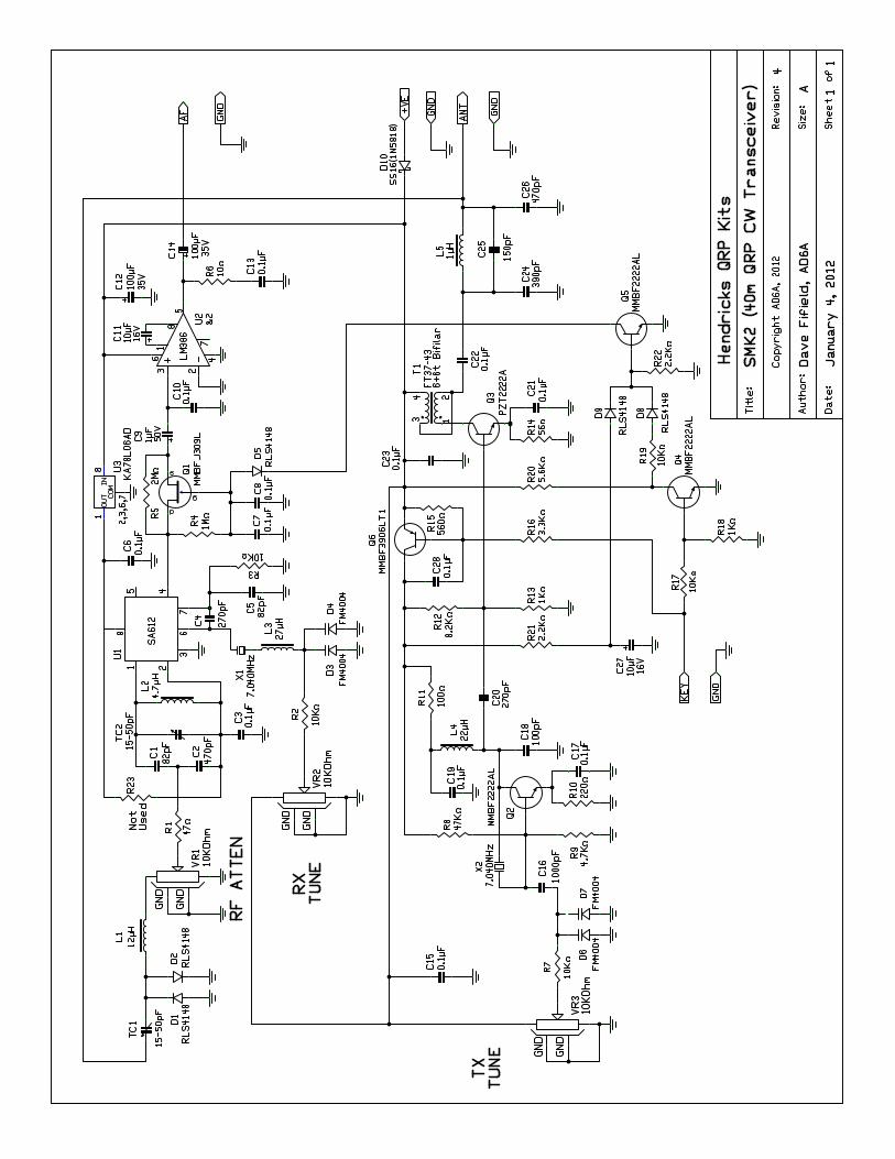
The SMK-2 circuit is basically a modified Tuna Tin 2 transmitter integrated with a modified MRX-40 receiver. It is a further modification of the modified TT2/MRX-40 that I built for the indoor foxhunt at Pacificon 1999. All this is fitted onto a small 2.475” x 2.25” PCB. The transmitter consists basically of the two 2N2222A transistor lineup of the original TT2 but with electronic keying. A key-switched crystal oscillator that has some degree of VXO feeds a medium power packaged version of the 2N2222A as a final in class A mode. After harmonic filtering, the result is about 350mW of fairly clean transmitting power on 7.030MHz (+/- a bit). The RX front end uses the ubiquitous NE602 mixer/oscillator with a crystal VXO. The RX is a direct conversion receiver, so you will hear both sidebands as you tune through a station. The audio output of the NE602 direct conversion front end goes through a FET switch that serves to mute the audio to an acceptable side tone level during TX and then on to a standard LM386 audio power amplifier running as much gain as it can. The three controls on the front panel of the SMK-2 are (left to right as you look at it): RF attenuation, RX tuning, and TX tuning. Operating the SMK-2 requires a little knowledge of where you are receiving and transmitting – there will be more on this in a later section of this manual.
© 2000, Red Hot Radio, © 2012, Hendricks QRP Kits – Unauthorized Copying or Publication Prohibited
3
Don’t Open The Parts Bags Yet – MUST READ! The kit contains mostly surface mount parts. Before you open the parts bag, please understand how you will identify them. The resistors are marked with a number code. A 222 means 2.2K resistor, etc. They are listed in the manual and on the parts list. The capacitors are not marked. We have used a color code for them, and the color code is listed in the manual and on the parts list. The transistors and diodes are also color coded, and the key is in the manual and on the parts list. The inductors are also marked; the key is also in the manual and on the parts list. Make sure that you pay attention and install the correct part. Do not take a part out of the carrier until you are ready to install it. The through-hole parts and the transmit output transformer are fitted last. Save the crystals, pots and trim caps till the end before you solder them in – it will make life much easier. Missing/Defective Parts We have made every effort to insure that all parts are included in your kit. However, due to the nature of the small surface mount components in the kit, it is very easy for you to lose parts and we anticipate that there will be some loss! Hendricks QRP Kits will replace parts for no charge, but you will need to send a self-addressed stamped envelope. Send your lost parts requirements to: Doug Hendricks, KI6DS 862 Frank Avenue Dos Palos CA 93620 USA Please include an SASE for the parts. Technical Support For complex problems or issues or if you don’t obtain satisfaction from the QRP-L email list, please email me at [email protected]
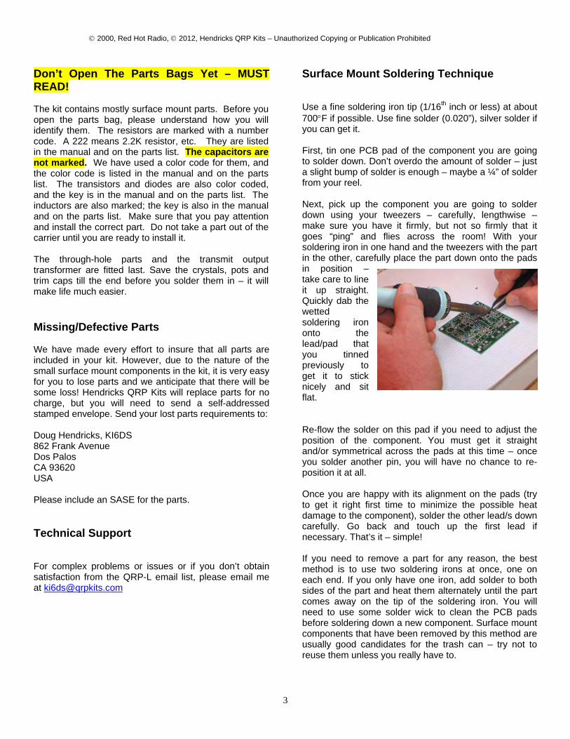
Surface Mount Soldering Technique Use a fine soldering iron tip (1/16th inch or less) at about 700°F if possible. Use fine solder (0.020”), silver solder if you can get it. First, tin one PCB pad of the component you are going to solder down. Don’t overdo the amount of solder – just a slight bump of solder is enough – maybe a ¼” of solder from your reel. Next, pick up the component you are going to solder down using your tweezers – carefully, lengthwise – make sure you have it firmly, but not so firmly that it goes “ping” and flies across the room! With your soldering iron in one hand and the tweezers with the part in the other, carefully place the part down onto the pads in position – take care to line it up straight. Quickly dab the wetted soldering iron onto the lead/pad that you tinned previously to get it to stick nicely and sit flat. Re-flow the solder on this pad if you need to adjust the position of the component. You must get it straight and/or symmetrical across the pads at this time – once you solder another pin, you will have no chance to re-position it at all. Once you are happy with its alignment on the pads (try to get it right first time to minimize the possible heat damage to the component), solder the other lead/s down carefully. Go back and touch up the first lead if necessary. That’s it – simple! If you need to remove a part for any reason, the best method is to use two soldering irons at once, one on each end. If you only have one iron, add solder to both sides of the part and heat them alternately until the part comes away on the tip of the soldering iron. You will need to use some solder wick to clean the PCB pads before soldering down a new component. Surface mount components that have been removed by this method are usually good candidates for the trash can – try not to reuse them unless you really have to.
© 2000, Red Hot Radio, © 2012, Hendricks QRP Kits – Unauthorized Copying or Publication Prohibited
4
Getting Started STEP 1: Capacitors Using a pair of scissors, cut open the parts bag containing the capacitors. This is the one with white parts marked with different colored ink. Use the pictures on page 9 to help separate and identify the capacitors. Install them in this order: □ 1. 13 x 0.1uF caps. They will all be in a strip. They
are marked with a black stripe. Remove and install one at a time at C3, C6, C7, C8, C10, C13, C15, C17, C19, C21, C22, C23, and C28.
□ 2. 3 x 82pF caps. They are marked with a blue stripe. They go at C1, C5, and C25.
□ 3. 1 x 100pF cap. It is marked with a brown stripe. It goes at C18.
□ 4. 2 x 270pF. It is marked with a red stripe. They go at C4, C20.
□ 5. 1 x 390pF. It is marked with an orange stripe. It goes at C24.
□ 6. 2 x 470pF. They are marked with a yellow stripe. They go at C2 and C26.
□ 7. 1 x 1000pF. It is marked with a green stripe and goes at C16.
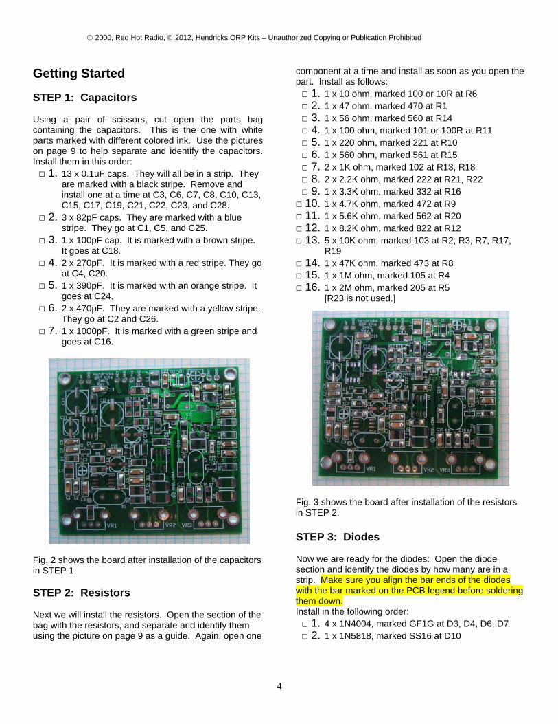
Fig. 2 shows the board after installation of the capacitors in STEP 1. STEP 2: Resistors Next we will install the resistors. Open the section of the bag with the resistors, and separate and identify them using the picture on page 9 as a guide. Again, open one
component at a time and install as soon as you open the part. Install as follows: □ 1. 1 x 10 ohm, marked 100 or 10R at R6 □ 2. 1 x 47 ohm, marked 470 at R1 □ 3. 1 x 56 ohm, marked 560 at R14 □ 4. 1 x 100 ohm, marked 101 or 100R at R11 □ 5. 1 x 220 ohm, marked 221 at R10 □ 6. 1 x 560 ohm, marked 561 at R15 □ 7. 2 x 1K ohm, marked 102 at R13, R18 □ 8. 2 x 2.2K ohm, marked 222 at R21, R22 □ 9. 1 x 3.3K ohm, marked 332 at R16 □ 10. 1 x 4.7K ohm, marked 472 at R9 □ 11. 1 x 5.6K ohm, marked 562 at R20 □ 12. 1 x 8.2K ohm, marked 822 at R12 □ 13. 5 x 10K ohm, marked 103 at R2, R3, R7, R17,
R19 □ 14. 1 x 47K ohm, marked 473 at R8 □ 15. 1 x 1M ohm, marked 105 at R4 □ 16. 1 x 2M ohm, marked 205 at R5
[R23 is not used.]
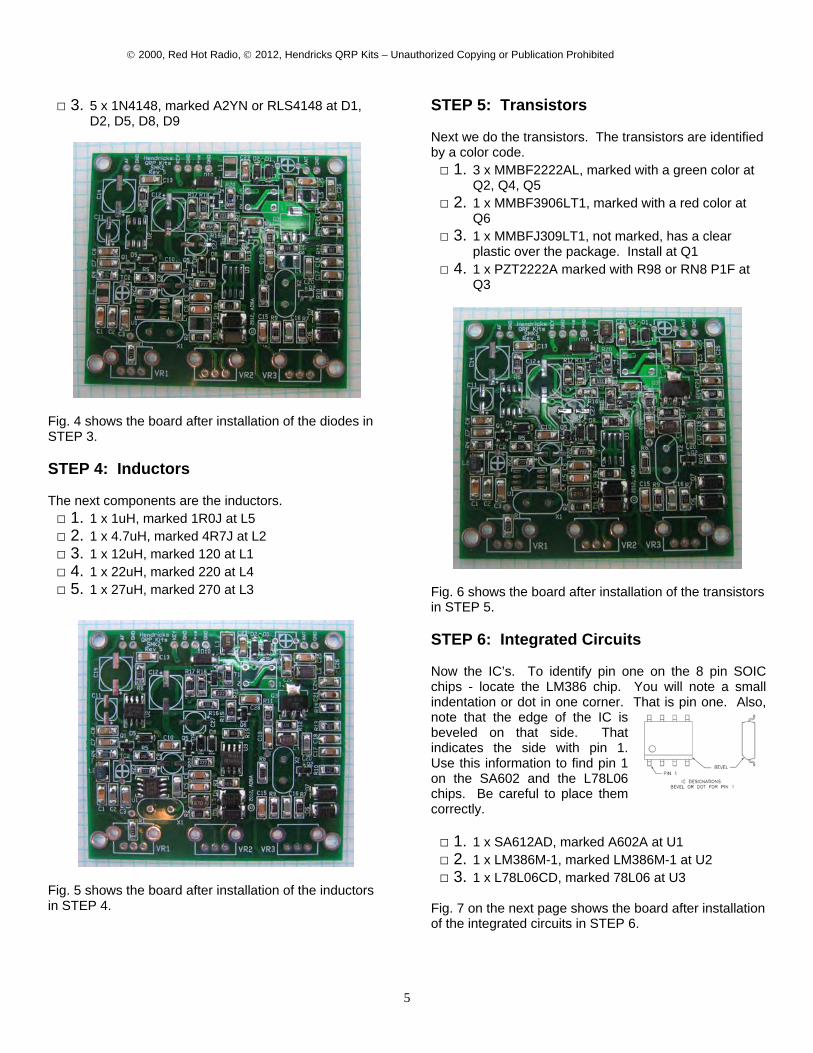
Fig. 3 shows the board after installation of the resistors in STEP 2. STEP 3: Diodes Now we are ready for the diodes: Open the diode section and identify the diodes by how many are in a strip. Make sure you align the bar ends of the diodes with the bar marked on the PCB legend before soldering them down. Install in the following order: □ 1. 4 x 1N4004, marked GF1G at D3, D4, D6, D7 □ 2. 1 x 1N5818, marked SS16 at D10
© 2000, Red Hot Radio, © 2012, Hendricks QRP Kits – Unauthorized Copying or Publication Prohibited
5
□ 3. 5 x 1N4148, marked A2YN or RLS4148 at D1, D2, D5, D8, D9
Fig. 4 shows the board after installation of the diodes in STEP 3. STEP 4: Inductors The next components are the inductors. □ 1. 1 x 1uH, marked 1R0J at L5 □ 2. 1 x 4.7uH, marked 4R7J at L2 □ 3. 1 x 12uH, marked 120 at L1 □ 4. 1 x 22uH, marked 220 at L4 □ 5. 1 x 27uH, marked 270 at L3
Fig. 5 shows the board after installation of the inductors in STEP 4.
STEP 5: Transistors Next we do the transistors. The transistors are identified by a color code. □ 1. 3 x MMBF2222AL, marked with a green color at
Q2, Q4, Q5 □ 2. 1 x MMBF3906LT1, marked with a red color at
Q6 □ 3. 1 x MMBFJ309LT1, not marked, has a clear
plastic over the package. Install at Q1 □ 4. 1 x PZT2222A marked with R98 or RN8 P1F at
Q3
Fig. 6 shows the board after installation of the transistors in STEP 5. STEP 6: Integrated Circuits Now the IC’s. To identify pin one on the 8 pin SOIC chips - locate the LM386 chip. You will note a small indentation or dot in one corner. That is pin one. Also, note that the edge of the IC is beveled on that side. That indicates the side with pin 1. Use this information to find pin 1 on the SA602 and the L78L06 chips. Be careful to place them correctly. □ 1. 1 x SA612AD, marked A602A at U1 □ 2. 1 x LM386M-1, marked LM386M-1 at U2 □ 3. 1 x L78L06CD, marked 78L06 at U3
Fig. 7 on the next page shows the board after installation of the integrated circuits in STEP 6.
© 2000, Red Hot Radio, © 2012, Hendricks QRP Kits – Unauthorized Copying or Publication Prohibited
6
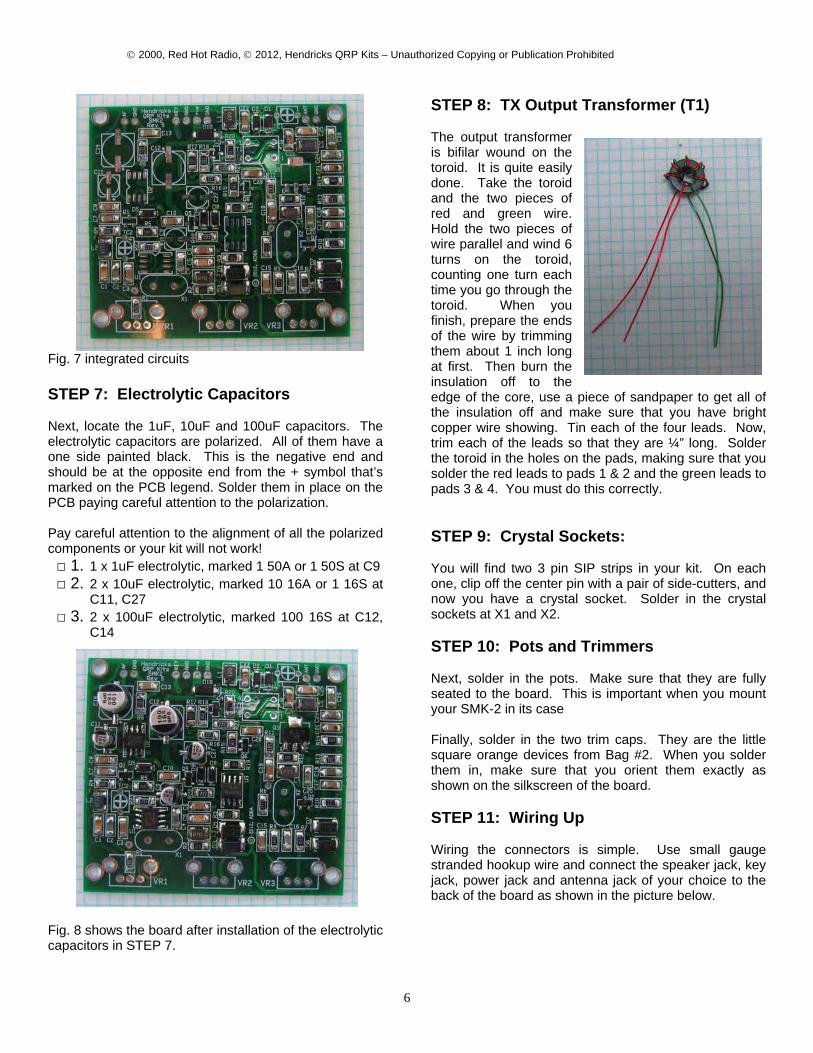
Fig. 7 integrated circuits STEP 7: Electrolytic Capacitors Next, locate the 1uF, 10uF and 100uF capacitors. The electrolytic capacitors are polarized. All of them have a one side painted black. This is the negative end and should be at the opposite end from the + symbol that’s marked on the PCB legend. Solder them in place on the PCB paying careful attention to the polarization. Pay careful attention to the alignment of all the polarized components or your kit will not work! □ 1. 1 x 1uF electrolytic, marked 1 50A or 1 50S at C9 □ 2. 2 x 10uF electrolytic, marked 10 16A or 1 16S at
C11, C27 □ 3. 2 x 100uF electrolytic, marked 100 16S at C12,
C14
Fig. 8 shows the board after installation of the electrolytic capacitors in STEP 7.
STEP 8: TX Output Transformer (T1) The output transformer is bifilar wound on the toroid. It is quite easily done. Take the toroid and the two pieces of red and green wire. Hold the two pieces of wire parallel and wind 6 turns on the toroid, counting one turn each time you go through the toroid. When you finish, prepare the ends of the wire by trimming them about 1 inch long at first. Then burn the insulation off to the edge of the core, use a piece of sandpaper to get all of the insulation off and make sure that you have bright copper wire showing. Tin each of the four leads. Now, trim each of the leads so that they are ¼” long. Solder the toroid in the holes on the pads, making sure that you solder the red leads to pads 1 & 2 and the green leads to pads 3 & 4. You must do this correctly. STEP 9: Crystal Sockets: You will find two 3 pin SIP strips in your kit. On each one, clip off the center pin with a pair of side-cutters, and now you have a crystal socket. Solder in the crystal sockets at X1 and X2. STEP 10: Pots and Trimmers Next, solder in the pots. Make sure that they are fully seated to the board. This is important when you mount your SMK-2 in its case Finally, solder in the two trim caps. They are the little square orange devices from Bag #2. When you solder them in, make sure that you orient them exactly as shown on the silkscreen of the board. STEP 11: Wiring Up Wiring the connectors is simple. Use small gauge stranded hookup wire and connect the speaker jack, key jack, power jack and antenna jack of your choice to the back of the board as shown in the picture below.

© 2000, Red Hot Radio, © 2012, Hendricks QRP Kits – Unauthorized Copying or Publication Prohibited
7
STEP 12: Testing Now it is time to test your efforts. Attach a dummy load. Then apply 12 volts. Check for smoke. (Hopefully there won’t be any!!) Replace the dummy load with an antenna. We will start with the receiver section. Plug in a set of headphones. Peak TC1 first to make sure that you have 2 peaks. Go for highest noise level or signal. Next peak TC2 for loudest signal. Next is the easy part; the transmitter. Plug in a key, and transmit. Monitor on another receiver to make sure that you are putting out power. If you have problems, go to QRP-L, and post your problem. There are literally thousands of fellow QRPers there who will be more than happy to help with your problem. FINAL STEP: Operation Test units of the SMK-2 have tuned just below the marked crystal frequencies. The amount of VXO range varies with different crystals and component tolerances. Test units varied 1000-4000 Hz on the receiver and 200-1500 Hz on the transmitter. Thus the transmitter is the limiting factor on making contacts. Use a transceiver to verify which side of your signal that you want to tune the receiver to. You will soon learn that a dc receiver has two sidebands, and that you want to be on the correct one to make contacts. Verify the correct sideband on a transceiver, and then note which way that you tune the receiver in relation to the tone, (whether it goes up or down in pitch as you tune). Don’t worry; you will soon get the hang of it. If you have questions, again, get on QRP-L, someone will be there to assist you. Again, the purpose of this kit was to assist you in learning how to work with surface mount parts. We believe that it succeeds, and for a very modest cost. The transceiver does work, and it is capable of making contacts. It is not an ICOM 706 by any means though.

© 2000, Red Hot Radio, © 2012, Hendricks QRP Kits – Unauthorized Copying or Publication Prohibited
8
SMK-2 Decal install and finish assembly
Thoroughly clean the surface of the panel to remove any oils or contamination. If you do not paint your case, we have found that moving the decals into position on a bare aluminum chassis is more difficult, due to the brushed surface, so we advise pre-coating the chassis with a light coating of the Krylon clear before applying the decals. The decals are applied the same as model decals. Cut around each group of text you wish to apply. It doesn’t have to be perfect as the background film is transparent. Apply the decals before you mount anything to the chassis. Use the above picture to get the correct spacing around the holes, as it is very easy to do a great decal installation and have a portion covered up with a knob. Trim around the decal. After trimming, place the decal in a bowl of lukewarm water, with a small drop of dish soap to reduce the surface tension, for 10-15 seconds. Using tweezers, handle carefully to avoid tearing. Start to slide the decal off to the side of the backing paper, and place the unsupported edge of the decal close to the final location. Hold the edge of the decal against the panel, with your finger, and slide the paper out from under the decal. You can slide the decal around to the right position, as it will float slightly on the film of water. Use a knife point or something sharp to do this. When in position, hold the edge of the decal with your finger and gently squeegee excess water out from under the decal with a tissue or paper towel. Work from the center, to both sides. Remove any bubbles by blotting or wiping gently to the sides. Do this for each decal, and take your time. Allow to set overnight, or speed drying by placing near a fan for a few of hours. When dry, spray two light coats of matte finish, Krylon, clear to seal and protect the decals, and allow the spray to dry in between coats. All decals come with two complete sets, in case you mess one up.
© 2000, Red Hot Radio, © 2012, Hendricks QRP Kits – Unauthorized Copying or Publication Prohibited
9
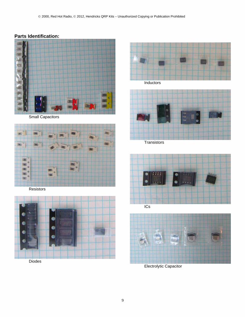
Parts Identification:
Small Capacitors
Resistors
Diodes
Inductors
Transistors
ICs
Electrolytic Capacitor

© 2000, Red Hot Radio, © 2012, Hendricks QRP Kits – Unauthorized Copying or Publication Prohibited
10
SMK-2 Parts List
Item # Description Package Value Quantity Marked Circuit References
1 Capacitor Ceramic NPO 1206 82pF 3 blue C1,5,25
2 Capacitor Ceramic NPO 1206 100pF 1 brown C18
3 Capacitor Ceramic NPO 1206 270pF 2 red C4,20
4 Capacitor Ceramic NPO 1206 390pF 1 orange C24
5 Capacitor Ceramic NPO 1206 470pF 3 yellow C2,26
6 Capacitor Ceramic NPO 1206 1000pF 3 green C16
7 Capacitor Ceramic X7R 1206 0.1uF 13 black C3, 6, 7, 8,
10,13,15,17,19, 21,22,23,28
8 Capacitor Aluminum Elec. B 1uF 50V 1 1 50A or 1 50S C9
9 Capacitor Aluminum Elec. B 10uF 16V 2 10 16A or 10 16S C11,27
10 Capacitor Aluminum Elec. D 100uF 16V 2 100-35V C12,14
11 Diode 1A (=1N4004) DO214 SS16 4 SS16 D3,4,6,7
12 Diode 1A (=1N5818) DO214 GF1G 1 GF1G D10
13 Diode Small Signal (=1N4148) LL-34 RLS4148 5 A2YN or RLS4148 D1,2,5,8,9
14 Inductor 1210 1uH 1 1R0 L5
15 Inductor 1210 4.7uH 1 4R7 L2
16 Inductor 1210 12uH 1 120 L1
17 Inductor 1210 22uH 1 220 L4
© 2000, Red Hot Radio, © 2012, Hendricks QRP Kits – Unauthorized Copying or Publication Prohibited
11
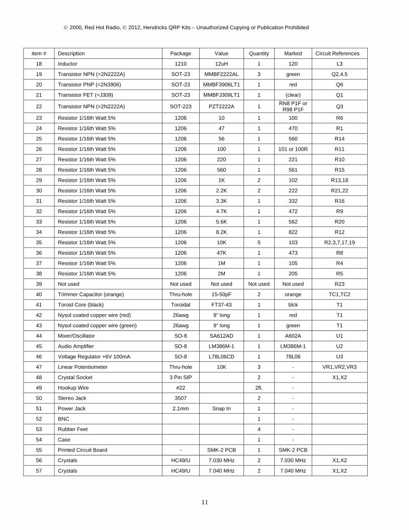
item # Description Package Value Quantity Marked Circuit References
18 Inductor 1210 12uH 1 120 L3
19 Transistor NPN (=2N2222A) SOT-23 MMBF2222AL 3 green Q2,4,5
20 Transistor PNP (=2N3906) SOT-23 MMBF3906LT1 1 red Q6
21 Transistor FET (=J309) SOT-23 MMBFJ309LT1 1 (clear) Q1
22 Transistor NPN (=2N2222A) SOT-223 PZT2222A 1 RN8 P1F or R98 P1F Q3
23 Resistor 1/16th Watt 5% 1206 10 1 100 R6
24 Resistor 1/16th Watt 5% 1206 47 1 470 R1
25 Resistor 1/16th Watt 5% 1206 56 1 560 R14
26 Resistor 1/16th Watt 5% 1206 100 1 101 or 100R R11
27 Resistor 1/16th Watt 5% 1206 220 1 221 R10
28 Resistor 1/16th Watt 5% 1206 560 1 561 R15
29 Resistor 1/16th Watt 5% 1206 1K 2 102 R13,18
30 Resistor 1/16th Watt 5% 1206 2.2K 2 222 R21,22
31 Resistor 1/16th Watt 5% 1206 3.3K 1 332 R16
32 Resistor 1/16th Watt 5% 1206 4.7K 1 472 R9
33 Resistor 1/16th Watt 5% 1206 5.6K 1 562 R20
34 Resistor 1/16th Watt 5% 1206 8.2K 1 822 R12
35 Resistor 1/16th Watt 5% 1206 10K 5 103 R2,3,7,17,19
36 Resistor 1/16th Watt 5% 1206 47K 1 473 R8
37 Resistor 1/16th Watt 5% 1206 1M 1 105 R4
38 Resistor 1/16th Watt 5% 1206 2M 1 205 R5
39 Not used Not used Not used Not used Not used R23
40 Trimmer Capacitor (orange) Thru-hole 15-50pF 2 orange TC1,TC2
41 Toroid Core (black) Toroidal FT37-43 1 blck T1
42 Nysol coated copper wire (red) 26awg 9" long 1 red T1
43 Nysol coated copper wire (green) 26awg 9" long 1 green T1
44 Mixer/Oscillator SO-8 SA612AD 1 A602A U1
45 Audio Amplifier SO-8 LM386M-1 1 LM386M-1 U2
46 Voltage Regulator +6V 100mA SO-8 L78L06CD 1 78L06 U3
47 Linear Potentiometer Thru-hole 10K 3 - VR1,VR2,VR3
48 Crystal Socket 3 Pin SIP 2 - X1,X2
49 Hookup Wire #22 2ft. -
50 Stereo Jack 3507 2 -
51 Power Jack 2.1mm Snap In 1 -
52 BNC 1 -
53 Rubber Feet 4 -
54 Case 1 -
55 Printed Circuit Board - SMK-2 PCB 1 SMK-2 PCB
56 Crystals HC49/U 7.030 MHz 2 7.030 MHz X1,X2
57 Crystals HC49/U 7.040 MHz 2 7.040 MHz X1,X2

© 2000, Red Hot Radio, © 2012, Hendricks QRP Kits – Unauthorized Copying or Publication Prohibited
12
© 2000, Red Hot Radio, © 2012, Hendricks QRP Kits – Unauthorized Copying or Publication Prohibited
14
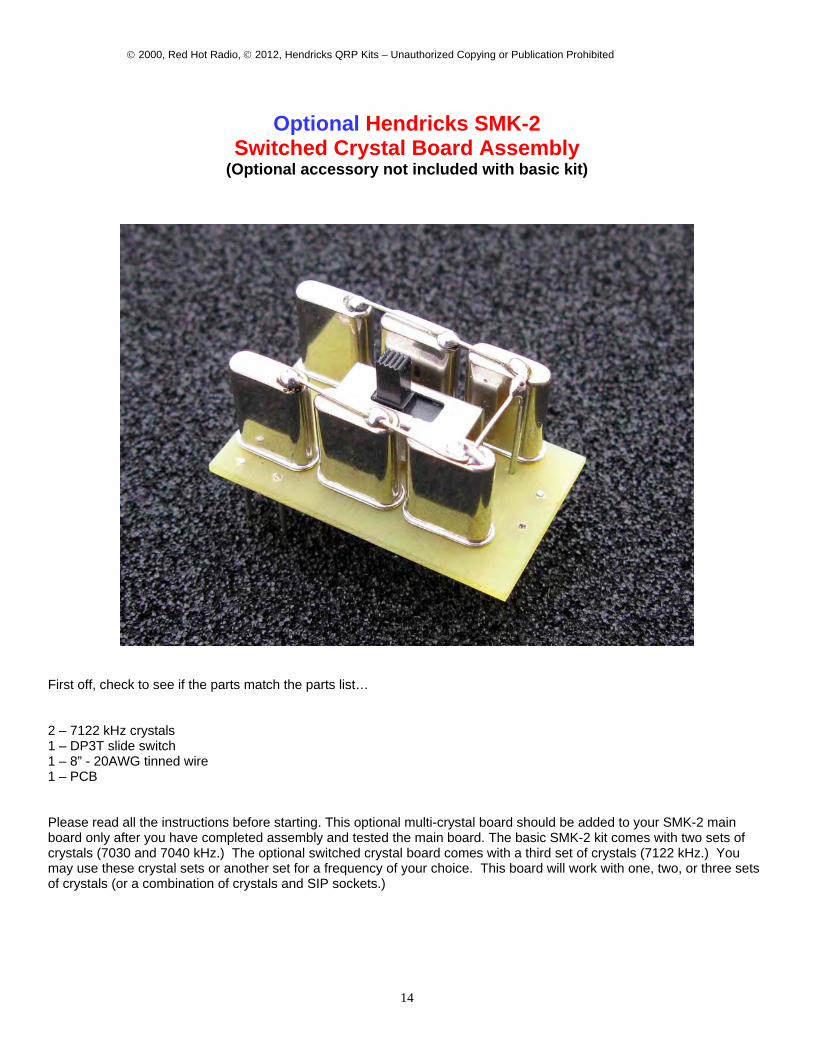
Optional Hendricks SMK-2 Switched Crystal Board Assembly
(Optional accessory not included with basic kit)
First off, check to see if the parts match the parts list… 2 – 7122 kHz crystals 1 – DP3T slide switch 1 – 8” - 20AWG tinned wire 1 – PCB Please read all the instructions before starting. This optional multi-crystal board should be added to your SMK-2 main board only after you have completed assembly and tested the main board. The basic SMK-2 kit comes with two sets of crystals (7030 and 7040 kHz.) The optional switched crystal board comes with a third set of crystals (7122 kHz.) You may use these crystal sets or another set for a frequency of your choice. This board will work with one, two, or three sets of crystals (or a combination of crystals and SIP sockets.)
© 2000, Red Hot Radio, © 2012, Hendricks QRP Kits – Unauthorized Copying or Publication Prohibited
15
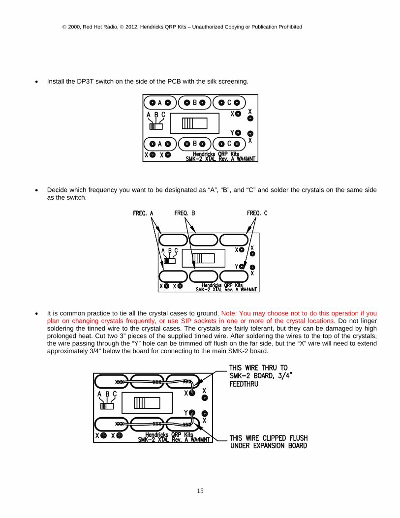
• Install the DP3T switch on the side of the PCB with the silk screening.
• Decide which frequency you want to be designated as “A”, “B”, and “C” and solder the crystals on the same side
as the switch.
• It is common practice to tie all the crystal cases to ground. Note: You may choose not to do this operation if you plan on changing crystals frequently, or use SIP sockets in one or more of the crystal locations. Do not linger soldering the tinned wire to the crystal cases. The crystals are fairly tolerant, but they can be damaged by high prolonged heat. Cut two 3” pieces of the supplied tinned wire. After soldering the wires to the top of the crystals, the wire passing through the “Y” hole can be trimmed off flush on the far side, but the “X” wire will need to extend approximately 3/4” below the board for connecting to the main SMK-2 board.
© 2000, Red Hot Radio, © 2012, Hendricks QRP Kits – Unauthorized Copying or Publication Prohibited
16
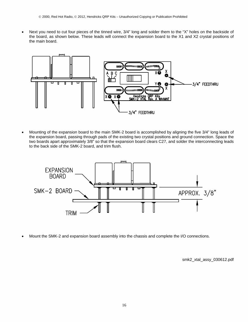
• Next you need to cut four pieces of the tinned wire, 3/4” long and solder them to the “X” holes on the backside of the board, as shown below. These leads will connect the expansion board to the X1 and X2 crystal positions of the main board.
• Mounting of the expansion board to the main SMK-2 board is accomplished by aligning the five 3/4” long leads of the expansion board, passing through pads of the existing two crystal positions and ground connection. Space the two boards apart approximately 3/8” so that the expansion board clears C27, and solder the interconnecting leads to the back side of the SMK-2 board, and trim flush.
• Mount the SMK-2 and expansion board assembly into the chassis and complete the I/O connections.
smk2_xtal_assy_030612.pdf