Embed Size (px)
Citation preview
PESA Eastern Australasian Basins Symposium II Adelaide, 19–22 September, 2004 431
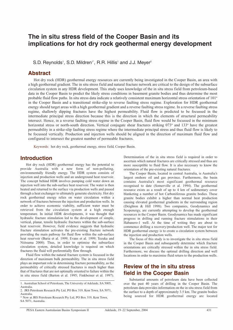
The in situ stress field of the Cooper Basin and itsimplications for hot dry rock geothermal energy development
AbstractHot dry rock (HDR) geothermal energy resources are currently being investigated in the Cooper Basin, an area with
a high geothermal gradient. The in situ stress field and natural fracture network are critical to the design of the subsurfacecirculation system in any HDR development. This study uses knowledge of the in situ stress field from petroleum-baseddata in the Cooper Basin to predict the likely stress conditions in basement granite bodies and thus determine the mostprobable fluid flow paths. In situ stress data indicate a relatively consistent maximum horizontal stress orientation of 101ºin the Cooper Basin and a transitional strike-slip to reverse faulting stress regime. Exploration for HDR geothermalenergy should target areas with a high geothermal gradient and a reverse faulting stress regime. In a reverse faulting stressregime, shallowly dipping fractures have the highest permeability. Fluid flow is predicted to be focussed in theintermediate principal stress direction because this is the direction in which the elements of structural permeabilityintersect. Hence, in a reverse faulting stress regime in the Cooper Basin, fluid flow would be focussed in the minimumhorizontal stress or north-south direction. Vertical conjugate shear fractures striking 073º and 133º have the greatestpermeability in a strike-slip faulting stress regime where the intermediate principal stress and thus fluid flow is likely tobe focussed vertically. Production and injection wells should be aligned in the direction of maximum fluid flow andconfigured to intersect the greatest number of permeable fractures.
Keywords: hot dry rock, geothermal energy, stress field, Cooper Basin.
S.D. Reynolds1, S.D. Mildren1*, R.R. Hillis1 and J.J. Meyer2
IntroductionHot dry rock (HDR) geothermal energy has the potential to
provide Australia with a new form of non-polluting,environmentally friendly energy. The HDR system consists ofinjection and production wells and an underground heat reservoir.The concept behind HDR involves pumping cold water down aninjection well into the sub-surface heat reservoir. The water is thenheated and returned to the surface via production wells and passedthrough a heat exchanger to ultimately generate electricity. Hot dryrock geothermal energy relies on water circulation within anetwork of fractures between the injection and production wells. Inorder to achieve economic viability, sufficient water must beretrieved from the circulation system at a high enoughtemperature. In initial HDR developments, it was thought thathydraulic fracture stimulation led to the development of simple,vertical, planar, tensile hydraulic fractures within the sub-surfaceheat reservoir. However, field evidence suggests that hydraulicfracture stimulation activates the pre-existing fracture networkproviding the main pathway for fluid flow within the sub-surfaceheat reservoir (Baria et al. 1999; Evans et al. 1999; Tezuka andNiitsuma 2000). Thus, in order to optimise the subsurfacecirculation system, detailed knowledge is required on whichfractures the fluid will preferentially flow through.
Fluid flow within the natural fracture system is focussed in thedirection of maximum bulk permeability. The in situ stress fieldplays an important role in determining fracture permeability, as thepermeability of critically stressed fractures is much higher thanthat of fractures that are not optimally oriented to failure within thein situ stress field (Barton et al. 1995; Finkbeiner et al. 1997).
Determination of the in situ stress field is required in order toascertain which natural fractures are critically stressed and thus aremore susceptible to fluid flow. It is also necessary to know theorientation of the pre-existing natural fractures.
The Cooper Basin, located in central Australia, is Australia’slargest onshore oil and gas province. Furthermore, the basincontains Australia’s most significant geothermal resourcerecognised to date (Somerville et al. 1994). The geothermalresource exists as a result of up to 4 km of sedimentary coverblanketing a number of hot Carboniferous granite bodies. Thesegranite bodies exhibit a higher than normal heat productioncausing elevated geothermal gradients in the surrounding region(Deighton & Hill 1998). Two companies, Geodynamics andScopenergy, are currently attempting to develop the geothermalresources in the Cooper Basin. Geodynamics has made significantprogress in drilling and running fracture stimulations in theirHabanero-1 well. At the time of writing they are about tocommence drilling a recovery/production well. The major test forHDR geothermal energy is to create a circulation system betweenthe injection and production wells.
The focus of this study is to investigate the in situ stress fieldin the Cooper Basin and subsequently determine which fractureorientations are critically stressed within the in situ stress field.Furthermore, we discuss the optimal drilling direction and welllocations in order to maximise fluid return to the production wells.
Review of the in situ stressfield in the Cooper Basin
Substantial amounts of petroleum data have been collectedover the past 40 years of drilling in the Cooper Basin. Thepetroleum data provides information on the in situ stress field fromthe surface to a depth of approximately 3.5 km. The granite bodiesbeing sourced for HDR geothermal energy are located
1. Australian School of Petroleum, The University of Adelaide, SA 5005,Australia.2. JRS Petroleum Research Pty Ltd, PO Box 319, Kent Town, SA 5071,Australia.* Now at JRS Petroleum Research Pty Ltd, PO Box 319, Kent Town, SA 5071, Australia.
432 PESA Eastern Australasian Basins Symposium II Adelaide, 19–22 September, 2004
S.D. REYNOLDS, S.D. MILDREN, R.R. HILLIS and J.J. MEYER
approximately 4 to 4.5 km deep. As a consequence, the in situstress field determined from the petroleum-based data isextrapolated to a depth of 4 km.
In order to define the in situ stress field, knowledge of theorientation and magnitude of the three principal stresses, and thepore pressure distribution is required. For the purpose of this study,we have made the common assumption that the vertical stress is aprincipal stress and hence the maximum and minimum horizontal
stresses are also principal stresses. This assumption is likely validgiven the relatively flat topography in this part of central Australia.
A number of the deeper petroleum wells in the basin, such asMoomba-73, have intersected granite bodies. Fractures have beeninterpreted in a granite body from Schlumberger’s FormationMicroScanner (FMS) log run in Moomba-73. These fractures havebeen used as an example dataset to assess the likelihood of an openfracture network within the granite bodies.
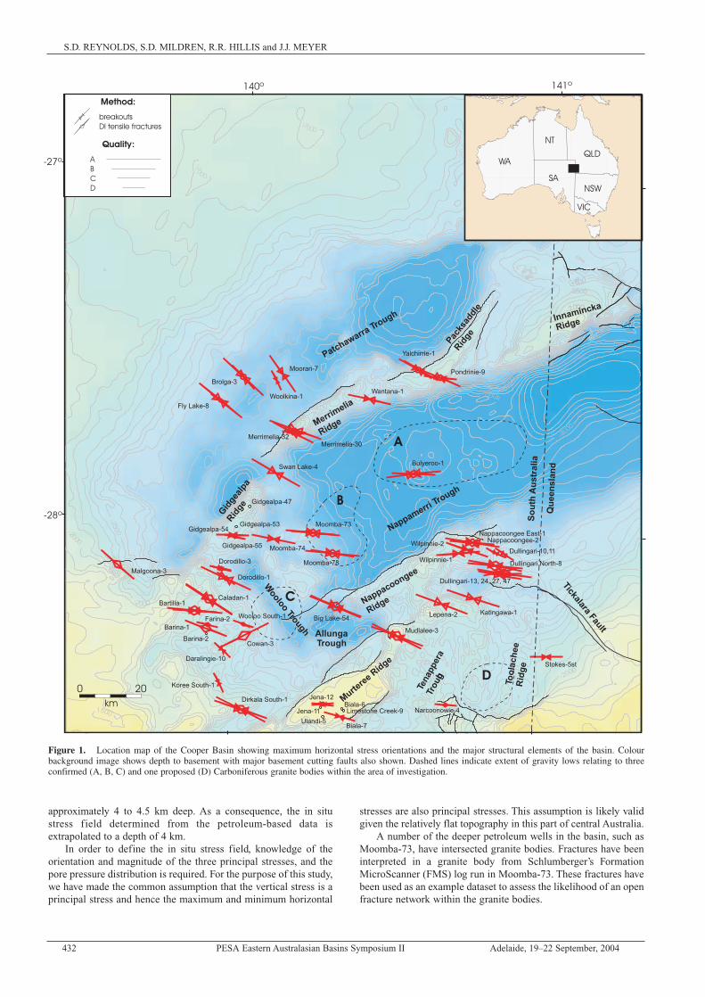
Figure 1. Location map of the Cooper Basin showing maximum horizontal stress orientations and the major structural elements of the basin. Colourbackground image shows depth to basement with major basement cutting faults also shown. Dashed lines indicate extent of gravity lows relating to threeconfirmed (A, B, C) and one proposed (D) Carboniferous granite bodies within the area of investigation.
PESA Eastern Australasian Basins Symposium II Adelaide, 19–22 September, 2004 433
THE IN SITU STRESS FIELD OF THE COOPER BASIN AND IMPLICATIONS FOR GEOTHERMAL ENERGY
Pore pressureKnowledge of the pore pressure distribution is required for the
accurate determination of the minimum and maximum horizontalstress magnitudes. A number of direct pressure measurements havebeen undertaken in the Cooper Basin. These measurements includedrill stem tests (DSTs) and wireline repeat formation tests (RFTs).Direct pressure measurements provide the most accurate porepressure estimates. However, their spatial and depth distribution isoften limited. A comparison of DSTs with mudweights fromconventionally drilled wells in the Cooper Basin has shown thatthey are generally consistent (van Ruth and Hillis 2000). Thus, inthe absence of direct pressure data mudweights have been used asa proxy for pore pressure. Mud weight can, with caution, be usedas a proxy for pore pressure, as mud weight is often just in excessof pore pressure to avoid drilling problems and maximise drillingefficiency. Care must be exercised to ensure any increases in mudweight are due to pore pressure changes and not, for example, toaddress wellbore stability issues.
The available pore pressure data indicates the Cooper Basin ison average hydrostatically pressured. However, a number of wellsdo indicate significant overpressures, which start at a depth ofaround 2,700 m. These wells include McLeod-1, Bulyeroo-1,Kirby-1, Burley-1, Burley-2 and Moomba-55, which are all locatedin the Nappamerri Trough (van Ruth and Hillis 2000). Theoverpressured units occur in the Toolachee formation and deeperunits (van Ruth & Hillis 2000). In addition, a number of directpressure measurements, largely from the Moomba field, indicateunderpressure, which is a result of draw down due to extensiveproduction in the basin over the past 40 years.
Due to the limited information on the distribution ofoverpressure, both laterally and vertically, we have assumedhydrostatic pore pressures for this study. Hence, only stressmeasurements at hydrostatic pressures have been examined toobtain estimates for the maximum and minimum horizontal stressmagnitudes. In regions where overpressure or underpressureoccurs, the results presented herein require modification.
Maximum horizontal stress orientationThe maximum horizontal stress orientation was determined
from borehole breakouts and drilling-induced tensile fractures(DITFs) interpreted from Cooper Basin image logs. Boreholebreakouts form when the circumferential stress acting around awellbore exceeds the compressive strength of the rock (Bell &Gough 1979; Zoback et al. 1985). When this arises in a verticalwell, conjugate shear fractures form at the wellbore wall centred onthe minimum horizontal stress direction, causing the rock to spalloff (Gough & Bell 1982). As a consequence, the wellbore becomesenlarged in the minimum horizontal stress direction. In contrast,DITFs form in the orientation of the maximum horizontal stresswhen the circumferential stress around the wellbore is less than thetensile strength of the rock (Brudy & Zoback 1999).
A total of 890 borehole breakouts and 608 DITFs wereinterpreted from 64 wells in the Cooper Basin. The meanmaximum horizontal stress orientation from all wells with A–Cquality borehole breakouts and DITFs is 101º (Reynolds et al.under review). Overall, the stress data for the Cooper Basinindicates a fairly consistent approximately east-west maximumhorizontal stress orientation. However, a number ofgeographic/geological domains have their own distinct stresstrends. Stress data from four wells in the Patchawarra Troughindicate a southeast-northwest maximum horizontal stressorientation (Fig. 1). Wells northeast of Gigealpa-47 on theGidgealpa-Merrimelia-Packsaddle ridge appear to have a west-northwest to east-southeast maximum horizontal stress orientation.In the Nappamerri Trough, the stress data indicates an east-westmaximum horizontal stress orientation. For the purpose of thisstudy, we have used the basin-averaged maximum horizontal stress
orientation of 101º, which corresponds more closely to themaximum horizontal stress orientation observed in the NappamerriTrough (location of the majority of the hot granite bodies; Fig. 1).The maximum horizontal stress orientation does not varysignificantly with depth in the basin. Hence, the approximate east-west maximum horizontal stress orientation can be extrapolatedwith reasonable confidence to the basement granites.
Vertical stress magnitudeThe vertical, or overburden stress, at a specified depth can be
equated with the pressure exerted by the weight of the overlyingrocks. Density log data are commonly run in petroleum wells andwas used to approximate the density of the rock column in order todetermine the magnitude of the vertical stress. Vertical stresscalculations require that the density log be integrated from thesurface. However, the density log is not commonly run from thesurface. The average density from the surface to the top of thedensity log run was estimated by converting checkshot velocitydata to density using the Nafe-Drake velocity/density transform(Ludwig et al. 1970).
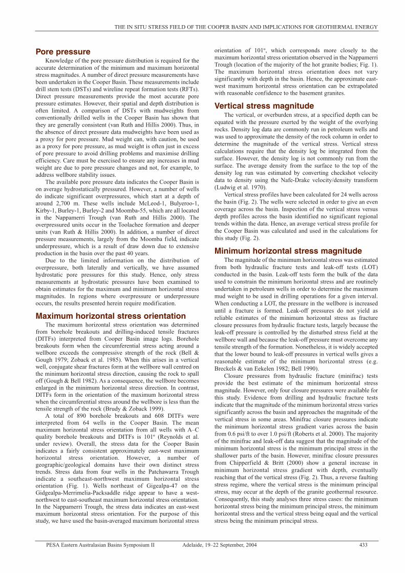
Vertical stress profiles have been calculated for 24 wells acrossthe basin (Fig. 2). The wells were selected in order to give an evencoverage across the basin. Inspection of the vertical stress versusdepth profiles across the basin identified no significant regionaltrends within the data. Hence, an average vertical stress profile forthe Cooper Basin was calculated and used in the calculations forthis study (Fig. 2).
Minimum horizontal stress magnitudeThe magnitude of the minimum horizontal stress was estimated
from both hydraulic fracture tests and leak-off tests (LOT)conducted in the basin. Leak-off tests form the bulk of the dataused to constrain the minimum horizontal stress and are routinelyundertaken in petroleum wells in order to determine the maximummud weight to be used in drilling operations for a given interval.When conducting a LOT, the pressure in the wellbore is increaseduntil a fracture is formed. Leak-off pressures do not yield asreliable estimates of the minimum horizontal stress as fractureclosure pressures from hydraulic fracture tests, largely because theleak-off pressure is controlled by the disturbed stress field at thewellbore wall and because the leak-off pressure must overcome anytensile strength of the formation. Nonetheless, it is widely acceptedthat the lower bound to leak-off pressures in vertical wells gives areasonable estimate of the minimum horizontal stress (e.g.Breckels & van Eekelen 1982; Bell 1990).
Closure pressures from hydraulic fracture (minifrac) testsprovide the best estimate of the minimum horizontal stressmagnitude. However, only four closure pressures were available forthis study. Evidence from drilling and hydraulic fracture testsindicate that the magnitude of the minimum horizontal stress variessignificantly across the basin and approaches the magnitude of thevertical stress in some areas. Minifrac closure pressures indicatethe minimum horizontal stress gradient varies across the basinfrom 0.6 psi/ft to over 1.0 psi/ft (Roberts et al. 2000). The majorityof the minifrac and leak-off data suggest that the magnitude of theminimum horizontal stress is the minimum principal stress in theshallower parts of the basin. However, minifrac closure pressuresfrom Chipperfield & Britt (2000) show a general increase inminimum horizontal stress gradient with depth, eventuallyreaching that of the vertical stress (Fig. 2). Thus, a reverse faultingstress regime, where the vertical stress is the minimum principalstress, may occur at the depth of the granite geothermal resource.Consequently, this study analyses three stress cases: the minimumhorizontal stress being the minimum principal stress, the minimumhorizontal stress and the vertical stress being equal and the verticalstress being the minimum principal stress.
434 PESA Eastern Australasian Basins Symposium II Adelaide, 19–22 September, 2004
S.D. REYNOLDS, S.D. MILDREN, R.R. HILLIS and J.J. MEYER
Figure 2. Stress magnitude verse depth plot for the Cooper Basin. Light gray lines are vertical stress profiles calculated at individual wells in the basin. Thered line is the average vertical stress profile for the basin and was used to estimate the vertical stress magnitude in this study. Shmin: minimum horizontalstress, Sv: vertical stress, Shmax: maximum horizontal stress, LOT: leak-off tests from Hillis et al. (1998), Minifracs: closure pressures from hydraulic fracturetests as reported by Chipperfield and Britt (2000).
PESA Eastern Australasian Basins Symposium II Adelaide, 19–22 September, 2004 435
THE IN SITU STRESS FIELD OF THE COOPER BASIN AND IMPLICATIONS FOR GEOTHERMAL ENERGY
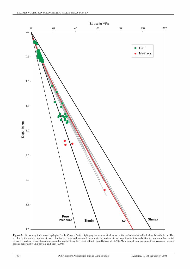
Maximum horizontal stress magnitudeThe magnitude of the maximum horizontal stress is generally
the most difficult component of the stress tensor to determine. Themagnitude of the maximum horizontal stress can be constrained byassuming that the ratio of the maximum to minimum effectivestress cannot exceed that required to cause faulting on an optimallyoriented pre-existing fault (Sibson 1974). The frictional limit tostress is given by Jaeger & Cook (1979):
1
where µ is the coefficient of friction on an optimally orientedpre-existing fault, S1 is the maximum principal stress, S3 is theminimum principal stress and Pp is the pore pressure. For a typicalvalue of µ=0.6:
2
This relationship can be used to estimate the magnitude of themaximum principal stress in seismically active regions (Zoback &Healy 1984) and provides an upper limit to the maximum principalstress in seismically inactive regions. In all three stress casesanalysed in this study, the maximum principal stress corresponds tothe maximum horizontal stress, assuming the maximum principalstress is at its frictional limits. Calculations of the maximumhorizontal stress were based on a hydrostatic pore pressure.
The first stress case assumes a lower bound for the minimumhorizontal stress of 0.68 times the vertical stress. Thecorresponding frictional limit to the maximum horizontal stressequates to 1.18 times the vertical stress (i.e. a strike-slip faultingstress regime). The second stress case assumes the minimumhorizontal stress and the vertical are equal (i.e. boundary of strike-slip to reverse faulting stress regime). Consequently, the frictionallimit to the maximum horizontal stress is 2.18 times the verticaland minimum horizontal stresses. Similarly, the maximumhorizontal stress is 2.18 times the vertical stress in the third stresscase when the vertical stress is the minimum principal stress (i.e. areverse faulting stress regime). The relative components of thestress tensor for the three stress cases are summarised in Table 1and can be converted to absolute stress magnitudes at 4 km depthby multiplying the table values by 91.42 MPa (vertical stressmagnitude at 4 km depth). The location of the three stress caseswithin the stress polygon space is plotted on Figure 3.
Optimising the sub-surfacecirculation system
Optimising the sub-surface circulation system requires detailedknowledge of the interaction between the in situ stress field, thepre-existing fracture network and the likelihood of creation of newfractures. The ultimate goal of the circulation system is tomaximise the amount of water recovered in the production wells atthe desired temperature. The identification of fracture orientationsthat are highly susceptible to fluid flow is required to achieve thisgoal. Critically stressed fractures within the in situ stress field havebeen found to have higher permeability than fractures that are notoptimally oriented within the in situ stress field (Barton et al. 1995;Finkbeiner et al. 1997).
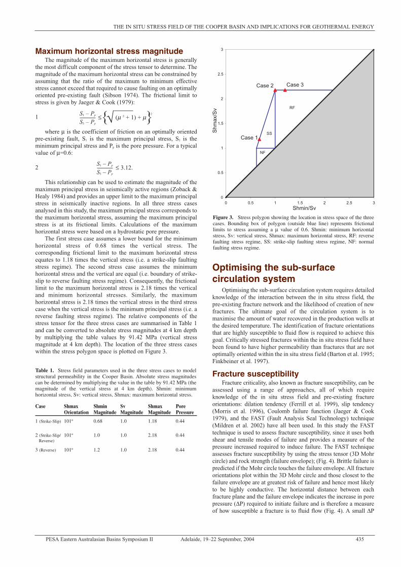
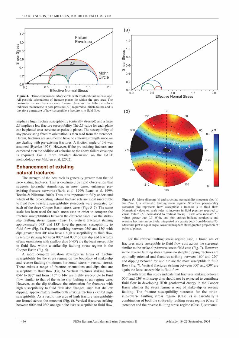
Fracture susceptibilityFracture criticality, also known as fracture susceptibility, can be
assessed using a range of approaches, all of which requireknowledge of the in situ stress field and pre-existing fractureorientations: dilation tendency (Ferrill et al. 1999), slip tendency(Morris et al. 1996), Coulomb failure function (Jaeger & Cook1979), and the FAST (Fault Analysis Seal Technology) technique(Mildren et al. 2002) have all been used. In this study the FASTtechnique is used to assess fracture susceptibility, since it uses bothshear and tensile modes of failure and provides a measure of thepressure increased required to induce failure. The FAST techniqueassesses fracture susceptibility by using the stress tensor (3D Mohrcircle) and rock strength (failure envelope); (Fig. 4). Brittle failure ispredicted if the Mohr circle touches the failure envelope. All fractureorientations plot within the 3D Mohr circle and those closest to thefailure envelope are at greatest risk of failure and hence most likelyto be highly conductive. The horizontal distance between eachfracture plane and the failure envelope indicates the increase in porepressure (∆P) required to initiate failure and is therefore a measureof how susceptible a fracture is to fluid flow (Fig. 4). A small ∆P
S1 – Pp
S3 – Pp
≤ √{ }(µ 2 + 1) + µ2
S1 – Pp
S3 – Pp
≤ 3.12.
Table 1. Stress field parameters used in the three stress cases to modelstructural permeability in the Cooper Basin. Absolute stress magnitudescan be determined by multiplying the value in the table by 91.42 MPa (themagnitude of the vertical stress at 4 km depth). Shmin: minimumhorizontal stress, Sv: vertical stress, Shmax: maximum horizontal stress.
Case Shmax Shmin Sv Shmax PoreOrientation Magnitude Magnitude Magnitude Pressure
1 (Strike-Slip) 101º 0.68 1.0 1.18 0.44
2 (Strike-Slip/ 101º 1.0 1.0 2.18 0.44Reverse)
3 (Reverse) 101º 1.2 1.0 2.18 0.44
Figure 3. Stress polygon showing the location in stress space of the threecases. Bounding box of polygon (outside blue line) represents frictionallimits to stress assuming a µ value of 0.6. Shmin: minimum horizontalstress, Sv: vertical stress, Shmax: maximum horizontal stress, RF: reversefaulting stress regime, SS: strike-slip faulting stress regime, NF: normalfaulting stress regime.
436 PESA Eastern Australasian Basins Symposium II Adelaide, 19–22 September, 2004
S.D. REYNOLDS, S.D. MILDREN, R.R. HILLIS and J.J. MEYER
implies a high fracture susceptibility (critically stressed) and a large∆P implies a low fracture susceptibility. The ∆P value for each planecan be plotted on a stereonet as poles to planes. The susceptibility ofany pre-existing fracture orientation is then read from the stereonet.Herein, fractures are assumed to have no cohesive strength since weare dealing with pre-existing fractures. A friction angle of 0.6 wasassumed (Byerlee 1978). However, if the pre-existing fractures arecemented then the addition of cohesion to the above failure envelopeis required. For a more detailed discussion on the FASTmethodology see Mildren et al. (2002).
Enhancement of existingnatural fractures
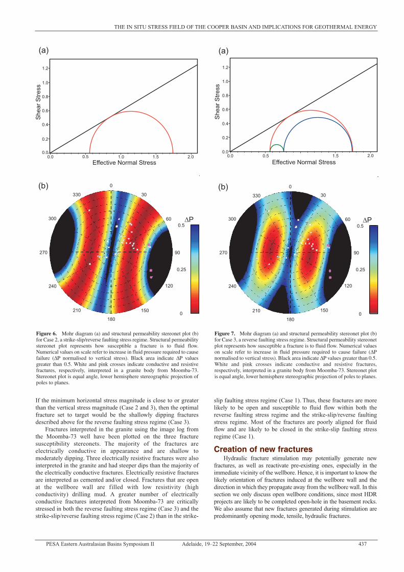
The strength of the host rock is generally greater than that ofpre-existing fractures. This is confirmed by field observation thatsuggests hydraulic stimulation, in most cases, enhances pre-existing fracture networks (Baria et al. 1999; Evans et al. 1999;Tezuka & Niitsuma 2000). Thus, it is important to fully understandwhich of the pre-existing natural fracture sets are most susceptibleto fluid flow. Fracture susceptibility stereonets were generated foreach of the three Cooper Basin stress cases (Figs 5–7). The samescale has been used for each stress case in order to compare thefracture susceptibilities between the different cases. For the strike-slip faulting stress regime (Case 1), vertical fractures strikingapproximately 073º and 133º have the greatest susceptibility tofluid flow (Fig. 5). Fractures striking between 050º and 150º withdips greater than 40º also have a high susceptibility to fluid flow.Fractures striking between 000º and 030º of any dip and fracturesof any orientation with shallow dips (<40º) are the least susceptibleto fluid flow within a strike-slip faulting stress regime in theCooper Basin (Fig. 5).
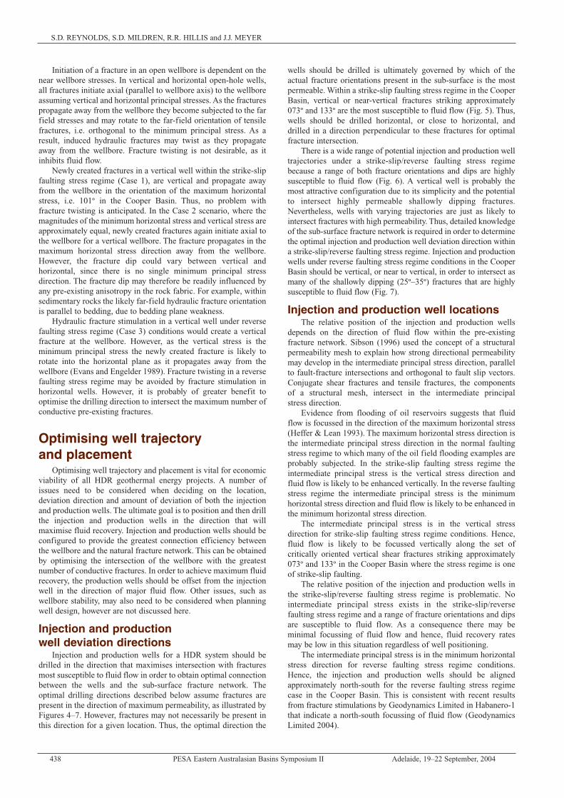
A more complex situation develops in terms of fracturesusceptibility for the stress regime on the boundary of strike-slipand reverse faulting (minimum horizontal stress = vertical stress).There exists a range of fracture orientations and dips that aresusceptible to fluid flow (Fig. 6). Vertical fractures striking from056º to 086º and from 116º to 146º are highly susceptible to fluidflow, similar to that of the strike-slip faulting stress regime case.However, as the dip shallows, the orientation for fractures withhigh susceptibility to fluid flow also changes, such that shallowdipping, approximately north-south striking fractures exhibit highsusceptibility. As a result, two arcs of high fracture susceptibilityare formed across the stereonet (Fig. 6). Vertical fractures strikingbetween 000º and 030º are again the least susceptible to fluid flow.
For the reverse faulting stress regime case, a broad arc offractures more susceptible to fluid flow cuts across the stereonetsimilar to the strike-slip/reverse stress field case (Fig. 7). However,in the reverse faulting stress regime no steeply dipping fractures areoptimally oriented and fractures striking between 160º and 220ºand dipping between 25º and 35º are the most susceptible to fluidflow (Fig. 7). Vertical fractures striking between 000º and 030º areagain the least susceptible to fluid flow.
Results from this study indicate that fractures striking between000º and 030º with steep dips should not be expected to contributefluid flow in developing HDR geothermal energy in the CooperBasin whether the stress regime is one of strike-slip or reversefaulting. The fracture susceptibility stereonet for the strike-slip/reverse faulting stress regime (Case 2) is essentially acombination of both the strike-slip faulting stress regime (Case 1)stereonet and the reverse faulting stress regime (Case 3) stereonet.
Figure 4. Three-dimensional Mohr circle with Coulomb failure envelope.All possible orientations of fracture planes lie within the grey area. Thehorizontal distance between each fracture plane and the failure envelopeindicates the increase in pore pressure (∆P) required to initiate failure and istherefore a measure of how susceptible a fracture is to fluid flow.
Figure 5. Mohr diagram (a) and structural permeability stereonet plot (b)for Case 1, a strike-slip faulting stress regime. Structural permeabilitystereonet plot represents how susceptible a fracture is to fluid flow.Numerical values on scale refer to increase in fluid pressure required tocause failure (∆P normalised to vertical stress). Black area indicate ∆Pvalues greater than 0.5. White and pink crosses indicate conductive andresistive fractures, respectively, interpreted in a granite body from Moomba-73.Stereonet plot is equal angle, lower hemisphere stereographic projection ofpoles to planes.
PESA Eastern Australasian Basins Symposium II Adelaide, 19–22 September, 2004 437
THE IN SITU STRESS FIELD OF THE COOPER BASIN AND IMPLICATIONS FOR GEOTHERMAL ENERGY
If the minimum horizontal stress magnitude is close to or greaterthan the vertical stress magnitude (Case 2 and 3), then the optimalfracture set to target would be the shallowly dipping fracturesdescribed above for the reverse faulting stress regime (Case 3).
Fractures interpreted in the granite using the image log fromthe Moomba-73 well have been plotted on the three fracturesusceptibility stereonets. The majority of the fractures areelectrically conductive in appearance and are shallow tomoderately dipping. Three electrically resistive fractures were alsointerpreted in the granite and had steeper dips than the majority ofthe electrically conductive fractures. Electrically resistive fracturesare interpreted as cemented and/or closed. Fractures that are openat the wellbore wall are filled with low resistivity (highconductivity) drilling mud. A greater number of electricallyconductive fractures interpreted from Moomba-73 are criticallystressed in both the reverse faulting stress regime (Case 3) and thestrike-slip/reverse faulting stress regime (Case 2) than in the strike-
slip faulting stress regime (Case 1). Thus, these fractures are morelikely to be open and susceptible to fluid flow within both thereverse faulting stress regime and the strike-slip/reverse faultingstress regime. Most of the fractures are poorly aligned for fluidflow and are likely to be closed in the strike-slip faulting stressregime (Case 1).
Creation of new fracturesHydraulic fracture stimulation may potentially generate new
fractures, as well as reactivate pre-existing ones, especially in theimmediate vicinity of the wellbore. Hence, it is important to know thelikely orientation of fractures induced at the wellbore wall and thedirection in which they propagate away from the wellbore wall. In thissection we only discuss open wellbore conditions, since most HDRprojects are likely to be completed open-hole in the basement rocks.We also assume that new fractures generated during stimulation arepredominantly opening mode, tensile, hydraulic fractures.
Figure 6. Mohr diagram (a) and structural permeability stereonet plot (b)for Case 2, a strike-slip/reverse faulting stress regime. Structural permeabilitystereonet plot represents how susceptible a fracture is to fluid flow.Numerical values on scale refer to increase in fluid pressure required to causefailure (∆P normalised to vertical stress). Black area indicate ∆P valuesgreater than 0.5. White and pink crosses indicate conductive and resistivefractures, respectively, interpreted in a granite body from Moomba-73.Stereonet plot is equal angle, lower hemisphere stereographic projection ofpoles to planes.
Figure 7. Mohr diagram (a) and structural permeability stereonet plot (b)for Case 3, a reverse faulting stress regime. Structural permeability stereonetplot represents how susceptible a fracture is to fluid flow. Numerical valueson scale refer to increase in fluid pressure required to cause failure (∆Pnormalised to vertical stress). Black area indicate ∆P values greater than 0.5.White and pink crosses indicate conductive and resistive fractures,respectively, interpreted in a granite body from Moomba-73. Stereonet plotis equal angle, lower hemisphere stereographic projection of poles to planes.
438 PESA Eastern Australasian Basins Symposium II Adelaide, 19–22 September, 2004
S.D. REYNOLDS, S.D. MILDREN, R.R. HILLIS and J.J. MEYER
Initiation of a fracture in an open wellbore is dependent on thenear wellbore stresses. In vertical and horizontal open-hole wells,all fractures initiate axial (parallel to wellbore axis) to the wellboreassuming vertical and horizontal principal stresses. As the fracturespropagate away from the wellbore they become subjected to the farfield stresses and may rotate to the far-field orientation of tensilefractures, i.e. orthogonal to the minimum principal stress. As aresult, induced hydraulic fractures may twist as they propagateaway from the wellbore. Fracture twisting is not desirable, as itinhibits fluid flow.
Newly created fractures in a vertical well within the strike-slipfaulting stress regime (Case 1), are vertical and propagate awayfrom the wellbore in the orientation of the maximum horizontalstress, i.e. 101º in the Cooper Basin. Thus, no problem withfracture twisting is anticipated. In the Case 2 scenario, where themagnitudes of the minimum horizontal stress and vertical stress areapproximately equal, newly created fractures again initiate axial tothe wellbore for a vertical wellbore. The fracture propagates in themaximum horizontal stress direction away from the wellbore.However, the fracture dip could vary between vertical andhorizontal, since there is no single minimum principal stressdirection. The fracture dip may therefore be readily influenced byany pre-existing anisotropy in the rock fabric. For example, withinsedimentary rocks the likely far-field hydraulic fracture orientationis parallel to bedding, due to bedding plane weakness.
Hydraulic fracture stimulation in a vertical well under reversefaulting stress regime (Case 3) conditions would create a verticalfracture at the wellbore. However, as the vertical stress is theminimum principal stress the newly created fracture is likely torotate into the horizontal plane as it propagates away from thewellbore (Evans and Engelder 1989). Fracture twisting in a reversefaulting stress regime may be avoided by fracture stimulation inhorizontal wells. However, it is probably of greater benefit tooptimise the drilling direction to intersect the maximum number ofconductive pre-existing fractures.
Optimising well trajectoryand placement
Optimising well trajectory and placement is vital for economicviability of all HDR geothermal energy projects. A number ofissues need to be considered when deciding on the location,deviation direction and amount of deviation of both the injectionand production wells. The ultimate goal is to position and then drillthe injection and production wells in the direction that willmaximise fluid recovery. Injection and production wells should beconfigured to provide the greatest connection efficiency betweenthe wellbore and the natural fracture network. This can be obtainedby optimising the intersection of the wellbore with the greatestnumber of conductive fractures. In order to achieve maximum fluidrecovery, the production wells should be offset from the injectionwell in the direction of major fluid flow. Other issues, such aswellbore stability, may also need to be considered when planningwell design, however are not discussed here.
Injection and productionwell deviation directions
Injection and production wells for a HDR system should bedrilled in the direction that maximises intersection with fracturesmost susceptible to fluid flow in order to obtain optimal connectionbetween the wells and the sub-surface fracture network. Theoptimal drilling directions described below assume fractures arepresent in the direction of maximum permeability, as illustrated byFigures 4–7. However, fractures may not necessarily be present inthis direction for a given location. Thus, the optimal direction the
wells should be drilled is ultimately governed by which of theactual fracture orientations present in the sub-surface is the mostpermeable. Within a strike-slip faulting stress regime in the CooperBasin, vertical or near-vertical fractures striking approximately073º and 133º are the most susceptible to fluid flow (Fig. 5). Thus,wells should be drilled horizontal, or close to horizontal, anddrilled in a direction perpendicular to these fractures for optimalfracture intersection.
There is a wide range of potential injection and production welltrajectories under a strike-slip/reverse faulting stress regimebecause a range of both fracture orientations and dips are highlysusceptible to fluid flow (Fig. 6). A vertical well is probably themost attractive configuration due to its simplicity and the potentialto intersect highly permeable shallowly dipping fractures.Nevertheless, wells with varying trajectories are just as likely tointersect fractures with high permeability. Thus, detailed knowledgeof the sub-surface fracture network is required in order to determinethe optimal injection and production well deviation direction withina strike-slip/reverse faulting stress regime. Injection and productionwells under reverse faulting stress regime conditions in the CooperBasin should be vertical, or near to vertical, in order to intersect asmany of the shallowly dipping (25º–35º) fractures that are highlysusceptible to fluid flow (Fig. 7).
Injection and production well locationsThe relative position of the injection and production wells
depends on the direction of fluid flow within the pre-existingfracture network. Sibson (1996) used the concept of a structuralpermeability mesh to explain how strong directional permeabilitymay develop in the intermediate principal stress direction, parallelto fault-fracture intersections and orthogonal to fault slip vectors.Conjugate shear fractures and tensile fractures, the componentsof a structural mesh, intersect in the intermediate principalstress direction.
Evidence from flooding of oil reservoirs suggests that fluidflow is focussed in the direction of the maximum horizontal stress(Heffer & Lean 1993). The maximum horizontal stress direction isthe intermediate principal stress direction in the normal faultingstress regime to which many of the oil field flooding examples areprobably subjected. In the strike-slip faulting stress regime theintermediate principal stress is the vertical stress direction andfluid flow is likely to be enhanced vertically. In the reverse faultingstress regime the intermediate principal stress is the minimumhorizontal stress direction and fluid flow is likely to be enhanced inthe minimum horizontal stress direction.
The intermediate principal stress is in the vertical stressdirection for strike-slip faulting stress regime conditions. Hence,fluid flow is likely to be focussed vertically along the set ofcritically oriented vertical shear fractures striking approximately073º and 133º in the Cooper Basin where the stress regime is oneof strike-slip faulting.
The relative position of the injection and production wells inthe strike-slip/reverse faulting stress regime is problematic. Nointermediate principal stress exists in the strike-slip/reversefaulting stress regime and a range of fracture orientations and dipsare susceptible to fluid flow. As a consequence there may beminimal focussing of fluid flow and hence, fluid recovery ratesmay be low in this situation regardless of well positioning.
The intermediate principal stress is in the minimum horizontalstress direction for reverse faulting stress regime conditions.Hence, the injection and production wells should be alignedapproximately north-south for the reverse faulting stress regimecase in the Cooper Basin. This is consistent with recent resultsfrom fracture stimulations by Geodynamics Limited in Habanero-1that indicate a north-south focussing of fluid flow (GeodynamicsLimited 2004).

PESA Eastern Australasian Basins Symposium II Adelaide, 19–22 September, 2004 439
THE IN SITU STRESS FIELD OF THE COOPER BASIN AND IMPLICATIONS FOR GEOTHERMAL ENERGY
Recommendations for future HDRexploration in the Cooper Basin
Detailed knowledge of the in situ stress field is currentlyrestricted to the sedimentary rocks overlying the granite bodies inthe Cooper Basin. In this study we have extrapolated the in situstress field to the depth of the granite bodies. Future explorationshould include in situ stress measurements within the granitebodies. Also, only limited knowledge of the natural fracturenetwork in the granite is available. Detailed knowledge of theactual fracture network is critical for well placement andconfiguration. Information on the in situ stress field and fracturenetwork can be obtained through the use of image logs. However,the high temperatures within the granite bodies means the imagetools are at the limit of their working environment and therefore theacquisition of oriented core is also recommended.
A reverse faulting stress regime provides the best in situ stressconditions for HDR geothermal energy development. Petroleum-based in situ stress data suggests that a reverse faulting stressregime may exist at the depth of HDR development in the CooperBasin. Future HDR exploration should preferentially select areaswith a reverse faulting stress regime in combination with highgeothermal gradients. In a reverse faulting stress regime, fluid flowis predicted to be along shallowly dipping fractures and focussed inthe minimum horizontal stress direction (i.e. approximately north-south in the Cooper Basin). In a strike-slip faulting stress regimefluid flow will occur along vertical fractures and hence fielddevelopment would be more problematic than in the reversefaulting stress regime case. Care should be taken when evaluatingareas where the magnitude of the minimum horizontal stress andvertical stress are approximately equal as fracture susceptibilitypredictions suggest that optimal fracture orientation for fluid flowis highly variable and therefore fluid recovery at the productionwell may be poor.
AcknowledgementsThe authors wish to thank Santos and Primary Industries and
Resources South Australia for providing access to image log data.The depth to basement map for the Cooper Basin was kindlyprovided by Primary Industries and Resources South Australia,Queensland Department of Mines and Energy, Northern TerritoryDepartment of Mines and Energy, Mineral Resources New SouthWales and Geoscience Australia. JRS Petroleum Research isthanked for the use of the SWIFT software package. This researchhas been part of the Australasian Stress Map project funded by anAustralian Research Council grant.
ReferencesBARIA, R., BAUMGÄRTNER, J., RUMMEL, F., PINE, R.J., and
SATO, Y., 1999. HDR/HWR reservoirs: concepts,understanding and creation. Geothermics, v. 28, 533–552.
BARTON, C.A., ZOBACK, M.D., and MOOS, D., 1995. Fluidflow along potentially active faults in crystalline rock.Geology, v. 23, 683–686.
BELL, J.S., 1990. The stress regime of the Scotian Shelf offshoreeastern Canada to 6 kilometres depth and implications forrock mechanics and hydrocarbon migration. In: Maury, V. andFourmaintraux, D. (Eds), Rock at Great Depth, Rotterdam,Balkema. 1,243–1,265.
BELL, J.S., and GOUGH, D.I., 1979. Northeast-southwestcompressive stress in Alberta-evidence from oil wells. Earthand Planetary Science Letters, v. 45, 475–482.
BRECKELS, I.M., and VAN EEKELEN, H.A.M., 1982.Relationship between horizontal stress and depth insedimentary basins. Journal of Petroleum Technology, v. 34,2,191–2,198.
BRUDY, M., and ZOBACK, M.D., 1999. Drilling-induced tensilewall-fractures: implications for determination of in situ stressorientation and magnitude. International Journal of RockMechanics and Mining Sciences, v. 36, 191–215.
BYERLEE, J., 1978. Friction of rocks. Pure and AppliedGeophysics, v. 116, 615–626.
CHIPPERFIELD, S.T., and BRITT, L.K., 2000. Application ofafter-closure analysis for improved fracture treatmentoptimisation: A Cooper Basin case study. SPE RockyMountain Regional/Low Permeability ReservoirsSymposium, Denver, Colorado, 1–15.
DEIGHTON, I., and HILL, A.J., 1998. Thermal and burial history.In: Gravestock, D. I., Hibburt, J.E. and Drexel, J.F. (Eds),Petroleum Geology of South Australia, Volume 4: Cooper Basin,Primary Industries and Resources South Australia, 143–156.
EVANS, K., and ENGELDER, T., 1989. Some problems inestimating horizontal stress magnitudes in "thrust" regimes.International Journal of Rock Mechanics, Mineral Scienceand Geomechanical Abstracts, v. 26, 647–660.
EVANS, K.F., CORNET, F.H., HASHIDA, T., HAYASHI, K., ITO,T., MATSUKI, K., and WALLROTH, T., 1999. Stress and rockmechanics issues of relevance to HDR/HWR engineeredgeothermal systems: review of developments during the past15 years. Geothermics, v. 28, 455–474.
FERRILL, D.A., WINTERLE, J., WITTMEYER, G., SIMS, D.,COLTON, S., ARMSTRONG, A., and MORRIS, A.P., 1999.Stressed rock strains groundwater at Yucca Mountain, Nevada.GSA Today, May, 1–8.
FINKBEINER, T., BARTON, C.A., and ZOBACK, M.D., 1997.Relationships among in situ stress, fractures and faults, andfluid flow: Monterey Formation, Santa Maria Basin,California. AAPG Bulletin, v. 81, 1,975–1,999.
GEODYNAMICS LIMITED, 2004. Quarterly Report periodending 31 December 2003.
GOUGH, D.I., and BELL, J.S., 1982. Stress orientations fromborehole wall fractures with examples from Colorado, eastTexas, and northern Canada. Canadian Journal of EarthSciences, v. 19, 1,358–1,370.
HEFFER, K.J., and LEAN, J.C., 1993. Earth stress orientation—acontrol on, and guide to, flooding directionality in a majorityof reservoirs. In: Linville, B. (Eds), ReservoirCharacterization III, PennWell Books, Tulsa.
HILLIS, R.R., MEYER, J.J., and REYNOLDS, S.D., 1998. TheAustralian stress map. Exploration Geophysics, v. 29, 420–427.
JAEGER, J.C., and COOK, N.G.W., 1979. Fundamentals of rockmechanics, 3rd ed. Chapman and Hall.
LUDWIG, W.J., NAFE, J.E., and DRAKE, C.L., 1970. SeismicRefraction. In: Maxwell, A.E. (Eds), The Sea: Ideas andObservations on Progress in the Study of the Seas, Vol. 4: NewConcepts of Sea Floor Evolution, Wiley-Interscience, NewYork. 53–84.
MILDREN, S.D., HILLIS, R.R., and KALDI, J., 2002. Calibratingpredictions of fault seal reactivation in the Timor Sea. APPEAJournal, v. 42, 187–202.
MORRIS, A., FERRILL, D.A., and HENDERSON, D.B., 1996. Slip-tendency analysis and fault reactivation. Geology, 24, 275–278.
REYNOLDS, S.D., MILDREN, S.D., HILLIS, R.R., MEYER, J.J.,and FLOTTMANN, T., under review. Maximum horizontalstress orientations in the Cooper Basin, Australia:Implications for plate scale tectonics and local stress sources.Geophysical Journal International.

440 PESA Eastern Australasian Basins Symposium II Adelaide, 19–22 September, 2004
S.D. REYNOLDS, S.D. MILDREN, R.R. HILLIS and J.J. MEYER
ROBERTS, G.A., CHIPPERFIELD, S.T., and MILLER, W.K.,2000. The evolution of a high-wellbore pressure loss treatmentstrategy for the Australian Cooper Basin. SPE AnnualTechnical Conference and Exhibition, Dallas, Texas, 1–12.
SIBSON, R.H., 1974. Frictional constraints on thrust, wrench andnormal faults. Nature, v. 249, 542–544.
SIBSON, R.H., 1996. Structural permeability of fluid-driven fault-fracture meshes. Journal of Structural Geology, v. 18,1,031–1,042.
SOMERVILLE, M., WYBORN, D., CHOPRA, P., RAHMAN, S.,ESTRELLA, D., and VAN DER MEULEN, T., 1994. Hot DryRocks Feasibility Study, Energy Research and DevelopmentCorporation (ERDC) Report 243, 133p.
TEZUKA, K., and NIITSUMA, H., 2000. Stress estimated usingmicroseismic clusters and its relationship to the fracturesystem of the Hijiori hot dry rock reservoir. EngineeringGeology, v. 56, 47–62.
VAN RUTH, P., and HILLIS, R., 2000. Estimating pore pressure inthe Cooper Basin, South Australia: sonic log method in anuplifted basin. Exploration Geophysics, v. 31, 441–447.
ZOBACK, M.D., and HEALY, J.H., 1984. Friction, faulting and insitu stress. Annales Geophysicae, v. 2, 689–698.
ZOBACK, M.D., MOOS, D., MASTIN, L., and ANDERSON,R.N., 1985. Well bore breakouts and in situ stress. Journal ofGeophysical Research, v. 90, 5,523–5,530.