Embed Size (px)
Citation preview

The Influence of Different Vibration Exciter Systems on High
Frequency Primary Calibration of Single-Ended
Accelerometers
A. Täubner1, H. Schlaak
1, M. Brucke
2, Th. Bruns
1
1Physikalisch-Technische Bundesanstalt (PTB), Bundesallee 100, 38816 Braunschweig, Germany
2SPEKTRA Schwingungstechnik und Akustik GmbH Dresden, Gostritzer Str. 61-63, 01217 Dresden,
Germany
e-mail: [email protected]
Abstract During the monitoring of the long term stability of two
accelerometers intended for the use in the CIPM Key Comparison CCAUV.V-
K2 significant deviations of the magnitude results of the single ended transducer
were discovered. These deviations depend on whether the calibration was
performed on an armature made of Beryllium or of ceramic. Further
investigations exhibited that this effect must be attributed to some not yet readily
understood dynamic process between the contact surfaces of accelerometer and
armature. The relative motion underlying the deviations have a significant
systematic influence already at 5 kHz and beyond. Therefore, the effect needs to
be considered in some way while comparing results within the key comparison,
as some laboratories are using Beryllium armatures and some are using ceramic
armatures.
The contribution describes the details and outcome of the investigations
performed on the topic so far and is intended to trigger the necessary discussion
of consequences and solutions.
1 Introduction, the disconcerting findings
Under the auspices of the Consultative Committee “Acoustic, Ultrasound and Vibration” (CCAUV) in 2008
the decision was made to start a new international Key Comparison in vibration, CCAUV.V-K2. The task of
the comparison would be to calibrate a single ended and a back-to-back type of accelerometer in the
frequency range from 10 Hz to 10 kHz with primary methods according to ISO 16063-11 [1]. In preparation
of this comparison the designated pilot laboratory, namely PTB, was already monitoring two artefacts since
late 2007. These accelerometers, a B&K 8305 and a B&K 8305-001, were periodically recalibrated every
month in order to confirm the stability of the devices. The calibration in the upper frequency range was
performed on the High Frequency Primary Acceleration Calibration Facility of the PTB using a modified1
vibration exciter (VE) from Bouche, where the accelerometer is mounted on an air borne Beryllium
1Differing from the commercially available VE from Bouche the PTB device has a replacement air bearing designed
and built in the PTB and a replacement zero positioning unit connected to the air bearing.

armature. Shortly before the scheduled start of the comparison in April 2009 the laboratory purchased a new
high frequency shaker from SPEKTRA Schwingungstechnik und Akustik GmbH (SPEKTRA), namely an
SE-09 type, which uses an airborne ceramic armature. During the subsequent monitoring calibrations with
the new vibration exciter the results of the back-to-back accelerometer (8305) were well confirmed.
However, the results of the single ended transducer (8305-001) exhibited a systematic deviation which
increased with rising frequency, starting at 5 kHz. The effect is depicted in Fig. 1. The relative deviation
went up to 3 % at 20 kHz. An instability of that order would have drawn the use of this individual artefact for
the key comparison into question. But a further recalibration on the original Bouche VE again reproduced the
original results.
The findings of a systematic deviation could be reproduced with other examples of this type of transducer.
Further investigations with a different single ended accelerometer of type 2270-M8 from Endevco exhibited
the same effect (but to a lower degree).
The question thus arising was, what is the origin of such deviations and what is the actual sensitivity of the
accelerometer. Several possible causes for the effect were investigated with the help of three different VE in
two laboratories and will be discussed in the subsequent text in order to draw a clearer picture of the
situation. The laboratories participating in the investigation were PTB and the accredited calibration lab of
SPEKTRA in Dresden. The exciters used by the laboratories together with some technical data are listed in
table 1.
Fig. 1 Diagram of the deviation of primary calibration results “magnitude
of complex sensitivity” on the modified Bouche and SE-09 vibration
exciters for two different examples of the B&K 8305 WH
accelerometer.
Table 1. Availability of the vibration exciters in the two laboratories and
some technical data of the VE
Modified Bouche SPEKTRA SE-09 ENDEVCO 2911
PTB
SPEKTRA
Material of armature Beryllium Ceramic Beryllium
Weight of armature 142 g 230 g 200 g
Density of armature 1860 kg/m³ 3200 kg/m³ 1860 kg/m³
Modulus of Elasticity 315 Gpa 385 Gpa 315 GPa

2 Basic assumptions
In order to find an explanation for the systematic effect several investigations were made as it will be
described in the following. However, after extensive technical discussion between the authors some basic
assumptions were made, which exclude some components because they were considered irrelevant for the
investigated deviations. Please note, that these components are not at all considered irrelevant for the primary
accelerometer calibration as a whole.
2.1 Base strain sensitivity
We consider the effect of base strain and the respective sensitivity component of the accelerometer negligible
for the comparison between the different VE. The flatness of the mounting surface is of the same quality for
all VE and the mounting torque was controlled by use of a measuring wrench to be (2,0± 0,1) N·m.
The fact that a lubricant was used between the mounting surfaces of accelerometer and armature should
finally equalize any difference in the base strain conditions on the different VE.
2.2 Disturbance of optical measurement
The surfaces of all used VE were polished to provide an undisturbed interferometric signal. The intensity
indicator of the Polytec Laser Vibrometers used in all systems was always beyond 90 % during the
measurement. Considering a disturbance from the optical quality of the measurement surface an increase of
this influence with increasing displacement amplitude was anticipated, however, the effect under
consideration increases with frequency, while the acceleration amplitude is held constant and thus the
displacement amplitude is drastically decreasing.
2.3 Internal acceleration to charge conversion
It is a very basic, seemingly trivial assumption, which should still be noted here, that the seismic system has
the same acceleration to charge conversion property with respect to the true acceleration at the base point of
the internal piezo stack no matter to what armature it is mounted. That means the accelerometer does not
change it's basic internal properties in dependence of the VE.
3 Influence of the mass of the armature on the frequency response of the accelerometer
The coupled mechanical system of the accelerometer with the armature could be described as a two-mass-
oscillator with one mass being that of the seismic mass and the second mass being the sum of the
armature and the base of the transducer . These masses are coupled via the stiffness and the
damping of the seismic system inside the transducer.
Fig. 2 Schematic of the single ended
transducer mounted on the armature of
the VE.
It follows directly from this model that the mechanical resonance frequency of the system is a function of the
masses coupled to the spring for a constant stiffness and damping.
For an excitation of the system with a driving force the equation of motion can be written as
(1)
With the ansatz
(2)
some calculation leads to the mechanical frequency response of the elongation of the seismic element:
(3)
From the dependence of this response on the reduced mass it is obvious, that the mechanical resonance of
the mounted system is changed, when the mass of the armature changes.
Note however, that the elongation is not the target measurand of an accelerometer calibration. The
measurand of interest is in fact the (complex) charge sensitivity I.e. the ratio of output charge to input
(base) acceleration. With the typical assumption for piezo electric elements, that the output charge is
proportional to the force acting on the elements and the fact that this force is one can write the
proportionality
(4)
With equations (1) and (2) it is straight forward to derive the relations
(5)
and
(6)
Thus it follows for the charge sensitivity
(7)
where the last step follows by re-substitution of according to the Ansatz (2). This shows clearly that
although the armature mass has an influence on the mechanical resonance, it does not influence the
frequency response of the charge sensitivity, which in turn depends for the assumed two mass system only on
the seismic mass .
4 Modal behaviour
With increasing excitation frequency the dynamic behaviour of the bulk material of the armature is of
increasing importance. Investigations with Laser scanning show, that the Eigenmodes of the armature body
lead to a deformation of the mounting surface, which again results in different acceleration amplitudes
measured at different positions on the surface. The outcome is that the accelerometer mounted on top of the
armature detects a different acceleration than what is measured by the Laser vibrometer next to it. Fig. (3) is
a pictorial description of the situation.
Fig. 3 Schematic of the effect of eigenmodes on the
displacement measured with the Laser

vibrometer
This problem was partly already addressed in other publications like [2] where an air bearing shaker with
Beryllium armature was taken as best reference. However, as we will see, the problem goes even further.
4.1 Finite Element Simulations
In order to get an impression of the influence of the modal deformation on the magnitude of acceleration on
the surface of an armature finite element simulations based on the geometry of the modified Bouche VE
were performed. Fig. (4) shows the meshed geometric model and a color coded result plot from the FEM
analysis [3].
Fig. 4 FEM analysis of the acceleration distribution on the top surface of the modified Bouche
VE at 20 kHz excitation frequency. On the left is the meshed geometric model on the
right a colour coded plot of results.
For the analysis a single geometric model was used, which was evaluated once setting the material properties
(elasticity, density) to those of Beryllium and a second time setting these properties to the values of the
ceramics. Considering a measurement point (Laser spot) at a radial distance of 12,5 mm from the centre, the
acceleration measured on the Beryllium armature is 0,45 % less than in the centre at 10 kHz, while that on
the ceramic armature is 0,65 % less. For a frequency of 20 kHz the difference for Beryllium is 1,5 % while it
is 2,7 % for the ceramic of the SE-09.
However, any confidence, that this is the explanation for the effect seen in the calibration results is in vain,
considering the sign of this deviations.
Considering that the deviation expresses a reduction of the measured acceleration in comparison to the
acceleration acting on the accelerometer, the magnitude of sensitivity determined on the SE-09 VE is
supposed to be systematically higher than that resulting from primary calibration on the modified Bouche
VE. This is due to the fact that for the definition of the magnitude of charge sensitivity the ratio of output
charge amplitude to input acceleration amplitude has to be calculated, that is the acceleration is in the
denominator.
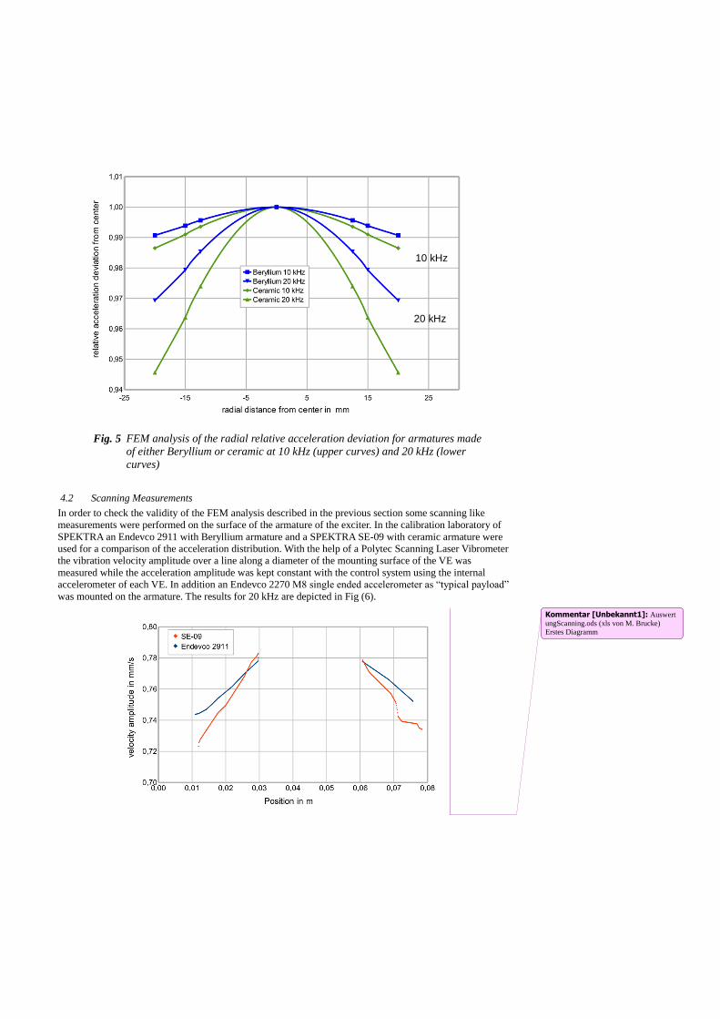
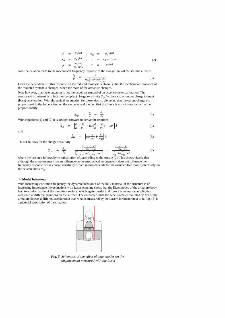
Fig. 5 FEM analysis of the radial relative acceleration deviation for armatures made
of either Beryllium or ceramic at 10 kHz (upper curves) and 20 kHz (lower
curves)
4.2 Scanning Measurements
In order to check the validity of the FEM analysis described in the previous section some scanning like
measurements were performed on the surface of the armature of the exciter. In the calibration laboratory of
SPEKTRA an Endevco 2911 with Beryllium armature and a SPEKTRA SE-09 with ceramic armature were
used for a comparison of the acceleration distribution. With the help of a Polytec Scanning Laser Vibrometer
the vibration velocity amplitude over a line along a diameter of the mounting surface of the VE was
measured while the acceleration amplitude was kept constant with the control system using the internal
accelerometer of each VE. In addition an Endevco 2270 M8 single ended accelerometer as “typical payload”
was mounted on the armature. The results for 20 kHz are depicted in Fig (6).
10 kHz
20 kHz
Kommentar [Unbekannt1]: Auswert
ungScanning.ods (xls von M. Brucke)
Erstes Diagramm
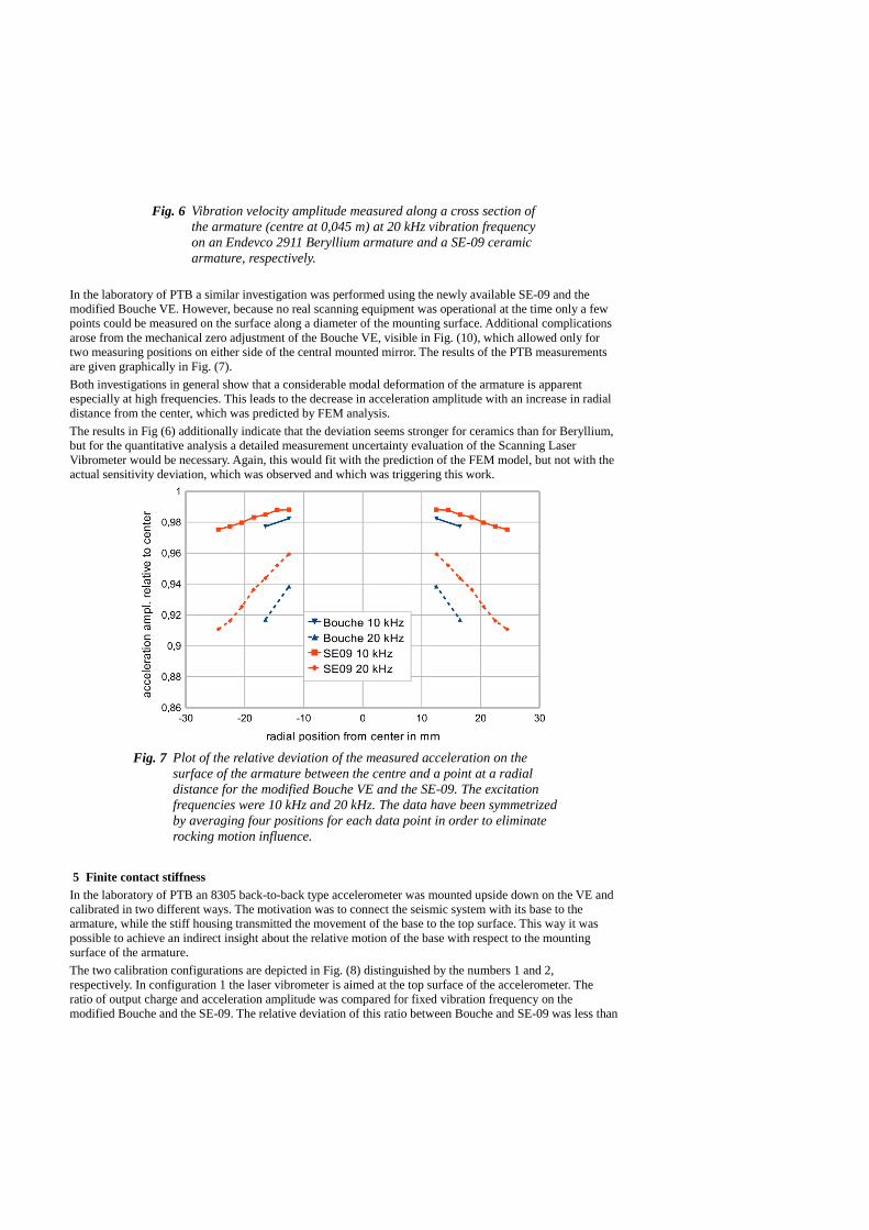
Fig. 6 Vibration velocity amplitude measured along a cross section of
the armature (centre at 0,045 m) at 20 kHz vibration frequency
on an Endevco 2911 Beryllium armature and a SE-09 ceramic
armature, respectively.
In the laboratory of PTB a similar investigation was performed using the newly available SE-09 and the
modified Bouche VE. However, because no real scanning equipment was operational at the time only a few
points could be measured on the surface along a diameter of the mounting surface. Additional complications
arose from the mechanical zero adjustment of the Bouche VE, visible in Fig. (10), which allowed only for
two measuring positions on either side of the central mounted mirror. The results of the PTB measurements
are given graphically in Fig. (7).
Both investigations in general show that a considerable modal deformation of the armature is apparent
especially at high frequencies. This leads to the decrease in acceleration amplitude with an increase in radial
distance from the center, which was predicted by FEM analysis.
The results in Fig (6) additionally indicate that the deviation seems stronger for ceramics than for Beryllium,
but for the quantitative analysis a detailed measurement uncertainty evaluation of the Scanning Laser
Vibrometer would be necessary. Again, this would fit with the prediction of the FEM model, but not with the
actual sensitivity deviation, which was observed and which was triggering this work.
Fig. 7 Plot of the relative deviation of the measured acceleration on the
surface of the armature between the centre and a point at a radial
distance for the modified Bouche VE and the SE-09. The excitation
frequencies were 10 kHz and 20 kHz. The data have been symmetrized
by averaging four positions for each data point in order to eliminate
rocking motion influence.
5 Finite contact stiffness
In the laboratory of PTB an 8305 back-to-back type accelerometer was mounted upside down on the VE and
calibrated in two different ways. The motivation was to connect the seismic system with its base to the
armature, while the stiff housing transmitted the movement of the base to the top surface. This way it was
possible to achieve an indirect insight about the relative motion of the base with respect to the mounting
surface of the armature.
The two calibration configurations are depicted in Fig. (8) distinguished by the numbers 1 and 2,
respectively. In configuration 1 the laser vibrometer is aimed at the top surface of the accelerometer. The
ratio of output charge and acceleration amplitude was compared for fixed vibration frequency on the
modified Bouche and the SE-09. The relative deviation of this ratio between Bouche and SE-09 was less than

0,25 % over the frequency range from 4 kHz to 20 kHz , which could be interpreted the way, that the
accelerometer's intrinsic behaviour is in no way depending on the armature it is mounted on. In addition it
shows that the effect we are looking for is not caused by electromagnetic cross talk.
In configuration 2 the laser vibrometer was aimed at the surface of the armature close to the accelerometer,
just like for a calibration of a single ended accelerometer. Again, the ratio of the output charge amplitude and
the acceleration amplitude was compared between the two VE. The result is given in the chart of Fig. (9).
The relative deviation rises up to almost 16 % at 20 kHz vibration and is about 2 % at10 kHz.
The sign of the deviation fits to the deviation of the original effect. Considering a constant acceleration of the
accelerometer base (shown with configuration 1) the acceleration amplitude measured by the laser
vibrometer on the Beryllium armature is higher than that on the ceramic armature. This effect is contrary to
that of the modal deformation discussed before.
Fig. 8 Measurement of a back-to-back accelerometer
mounted upside-down in two different
configurations (1 and 2).
A possible explanation of the described results is a finite contact stiffness, which could be visualized as a
sinking in of the accelerometer into the surface of the armature. However, considering a typical displacement
amplitude of 5 nm at 20 kHz this relative motion difference is in the order of 100 pm, which is in the order of
the diameter of a single atom.
These results were also reproduced by Laser scanning measurements performed in the laboratory of
SPEKTRA, where the top surface of an reversed mounted B&K 8305-001 was included in the scanned area
or the armature's surface.
VE armature B2B-Accelerometer
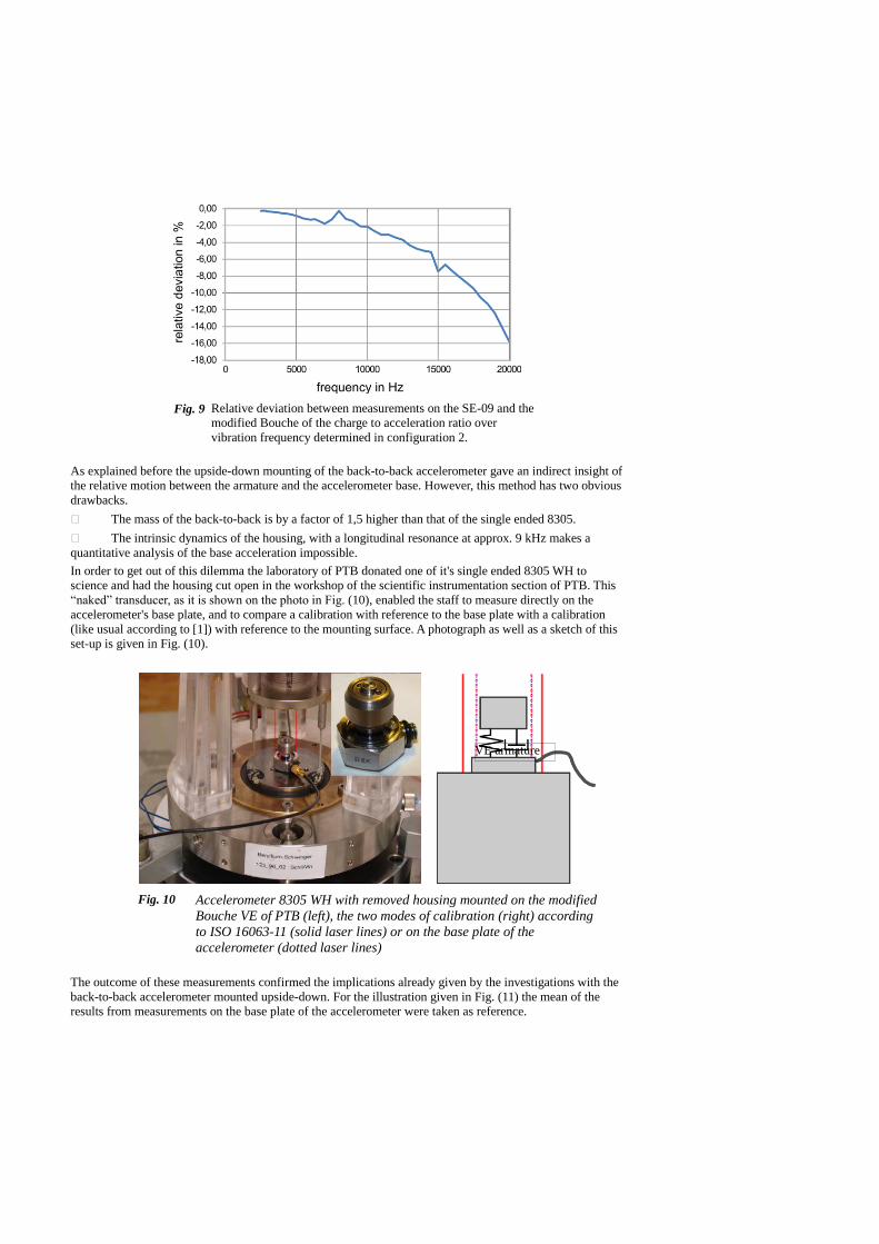
Fig. 9 Relative deviation between measurements on the SE-09 and the
modified Bouche of the charge to acceleration ratio over
vibration frequency determined in configuration 2.
As explained before the upside-down mounting of the back-to-back accelerometer gave an indirect insight of
the relative motion between the armature and the accelerometer base. However, this method has two obvious
drawbacks.
The mass of the back-to-back is by a factor of 1,5 higher than that of the single ended 8305.
The intrinsic dynamics of the housing, with a longitudinal resonance at approx. 9 kHz makes a
quantitative analysis of the base acceleration impossible.
In order to get out of this dilemma the laboratory of PTB donated one of it's single ended 8305 WH to
science and had the housing cut open in the workshop of the scientific instrumentation section of PTB. This
“naked” transducer, as it is shown on the photo in Fig. (10), enabled the staff to measure directly on the
accelerometer's base plate, and to compare a calibration with reference to the base plate with a calibration
(like usual according to [1]) with reference to the mounting surface. A photograph as well as a sketch of this
set-up is given in Fig. (10).
Fig. 10 Accelerometer 8305 WH with removed housing mounted on the modified
Bouche VE of PTB (left), the two modes of calibration (right) according
to ISO 16063-11 (solid laser lines) or on the base plate of the
accelerometer (dotted laser lines)
The outcome of these measurements confirmed the implications already given by the investigations with the
back-to-back accelerometer mounted upside-down. For the illustration given in Fig. (11) the mean of the
results from measurements on the base plate of the accelerometer were taken as reference.
VE armature
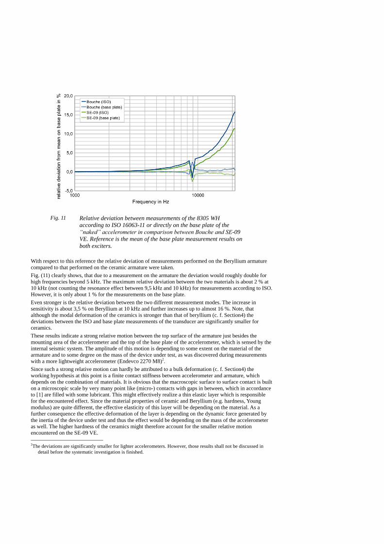
Fig. 11 Relative deviation between measurements of the 8305 WH
according to ISO 16063-11 or directly on the base plate of the
“naked” accelerometer in comparison between Bouche and SE-09
VE. Reference is the mean of the base plate measurement results on
both exciters.
With respect to this reference the relative deviation of measurements performed on the Beryllium armature
compared to that performed on the ceramic armature were taken.
Fig. (11) clearly shows, that due to a measurement on the armature the deviation would roughly double for
high frequencies beyond 5 kHz. The maximum relative deviation between the two materials is about 2 % at
10 kHz (not counting the resonance effect between 9,5 kHz and 10 kHz) for measurements according to ISO.
However, it is only about 1 % for the measurements on the base plate.
Even stronger is the relative deviation between the two different measurement modes. The increase in
sensitivity is about 3,5 % on Beryllium at 10 kHz and further increases up to almost 16 %. Note, that
although the modal deformation of the ceramics is stronger than that of beryllium (c. f. Section4) the
deviations between the ISO and base plate measurements of the transducer are significantly smaller for
ceramics.
These results indicate a strong relative motion between the top surface of the armature just besides the
mounting area of the accelerometer and the top of the base plate of the accelerometer, which is sensed by the
internal seismic system. The amplitude of this motion is depending to some extent on the material of the
armature and to some degree on the mass of the device under test, as was discovered during measurements
with a more lightweight accelerometer (Endevco 2270 M8)2.
Since such a strong relative motion can hardly be attributed to a bulk deformation (c. f. Section4) the
working hypothesis at this point is a finite contact stiffness between accelerometer and armature, which
depends on the combination of materials. It is obvious that the macroscopic surface to surface contact is built
on a microscopic scale by very many point like (micro-) contacts with gaps in between, which in accordance
to [1] are filled with some lubricant. This might effectively realize a thin elastic layer which is responsible
for the encountered effect. Since the material properties of ceramic and Beryllium (e.g. hardness, Young
modulus) are quite different, the effective elasticity of this layer will be depending on the material. As a
further consequence the effective deformation of the layer is depending on the dynamic force generated by
the inertia of the device under test and thus the effect would be depending on the mass of the accelerometer
as well. The higher hardness of the ceramics might therefore account for the smaller relative motion
encountered on the SE-09 VE.
2The deviations are significantly smaller for lighter accelerometers. However, those results shall not be discussed in
detail before the systematic investigation is finished.


Fig. 12 Pictorial explanation of the two counter acting
effects of modal deformation and finite contact
stiffness. With higher modal deformation of the
ceramics but still smaller relative motion due to
the contact stiffness
Figure 12 is an attempt to visualize the two counteracting effects discussed in this contribution, the
modal deformation as a bulk effect and the finite contact stiffness as an effect at the coupling
surfaces.
1 Summary and conclusion
An unknown systematic effect with a significant influence on the calibration results for primary calibration
of single ended accelerometers was discovered more or less incidentally by PTB. The effect is characterized
as it seems by a material dependency of the measured magnitude of sensitivity. The effect is not easily
explained by modal bulk deformations of the armature, but originates from some not yet fully understood
complex processes probably at the contact surfaces between accelerometer and armature of the vibration
exciter. The systematic deviation for the calibration results achieved on different exciters becomes significant
for frequencies beyond 5 kHz, it can rise up to 2 % at 10 kHz or even beyond 4 % at 20 kHz due to this
effect.
These findings draw the use of this type of single ended accelerometers in high frequency key comparisons
seriously into question. However, for other types of accelerometers the knowledge about the metrological
characteristics, especially the long term stability and low sensitivity to disturbing components are so far
insufficient for the use in international key comparisons.
Apart from the topic of key comparisons the critical question arises, what happens in the case where, e.g. a
transfer standard is calibrated on a exciter of material A, say Beryllium, and later on used to provide
traceability to a system of material B, say steel. This problem should be further investigated by the
international community of vibration metrologists and possible solutions, how to handle the consequences of
the described effect, should be discussed in the near future.
2 Bibliographie
[1] ISO 16063-11:1999, Methods for the calibration of vibration and shock transducers --
Part 11: Primary vibration calibration by laser interferometry, International Organization for
Standardization, Geneva (1999)
[2] G. Ripper, G. A. Garcia, R. S. Dias, Primary accelerometer Calibration Problems due to
Vibration Exciters, XVIII IMEKO World Congress “metrology for a sustainable
Development”, 2006, Rio de Janeiro, Brazil,
http://www.imeko.org/publications/wc-2006/PWC-2006-TC22-008u.pdf
[3] Software COMSOL Multiphysics V 3.4, COMSOL AB, Stockholm