Embed Size (px)
Citation preview

The Long-Term Performance of Surface Support Liners for Ground Control in A Underground Limestone Mine Deno M. Pappas, Timothy M. Barton, Eric S. Weiss National Institute for Occupational Safety and Health, Pittsburgh Research Laboratory, P.O. Box 18070, Cochrans Mill Road, Pittsburgh, PA, USA, 15236 National Institute for Occupational Safety and Health, Pittsburgh Research Laboratory, P.O. Box 18070, Cochrans Mill Road, Pittsburgh, PA, USA, 15236 National Institute for Occupational Safety and Health, Lake Lynn Laboratory, P.O. Box 528, Fairchance , PA, USA, 15436
Abstract During the past few years, the Pittsburgh Research Laboratory of the National Institute for Occupational Safety and Health (NIOSH) has been evaluating developments with surface support liners which includes shotcrete and thin spray-on liners (also referred to as sealants, coatings and membranes) from a ground control perspective. The proper selection and use of a surface support material can significantly enhance ground control which may result in a decrease in worker related injuries due to ground falls. The purpose of this paper is to evaluate the preliminary findings of a long-term underground study of various types of surface support liners, and to examine installation practices that are critical for an effective liner material application. The underground study utilizes NIOSH’s Lake Lynn Laboratory Experimental Mine to evaluate the long-term performance of several types of shotcrete and thin spray-on liner materials. Liner material performance to date was evaluated on a regular basis over a three year period. Although the study is still ongoing, critical mining practices were identified that may seriously affect the bond of the liner material to the mine roof and rib.
1 INTRODUCTION Most underground mines in the United States are composed of deteriorated rock of some
degree. When this rock is exposed to a cyclical weathering process, it often accelerates the deterioration of the mine roof or rib. This presents a stability problem and potential safety hazard for underground workers. In underground coal mines for instance, it is estimatedthat over 400 injuries occur annually due to skin failure of the roof or rib in permanently supported areas of the mine (Molinda, et al., 2002). Critical and long-life areas in the mine, such as the shafts, shops, beltways, haulage ways, and overcasts, can often experienceweathering over time which may require remedial support to arrest this process. These surface support methods include additional bolting, wire meshing, or sealing the weathered rock with materials such as shotcrete. Shotcrete, or pneumatically sprayed concrete, offersthe benefits of low cost, high compressive strength, high tolerance for humid conditions, and a good long-term performance record.
The newest generation of surface support liners are materials known as thin spray-onliner materials (also referred to sealants, coatings and membranes). Liners can generically be classified as multi-component polymeric material and offer these advantages: fast application rates, fast setting times, reduced material handling underground, good tensilestrength, excellent elongation properties, and good bond strength. Although shotcrete offers excellent rigid support, most thin spray-on liner materials can provide active support where the elastic liner supplies resistance as it deforms due to failure of the rock. Thin

spray-on liner materials are considered an emerging technology and are gaining favor in an increasing number of mines.
More information on recent developments with the use of shotcrete and thin spray-on liner materials is discussed further in other publications (Espley, et al., 2001; Rispin, et al., 1999; Espley, et al., 2001; Baiden, 1999; Spearing and Champa, 2001; Pappas, et al., 2002).
This paper presents preliminary results of a three year comparison study of several types of surface support liners in an underground environment and reviews critical practices in effectively using liner materials.
Figure 1 - Shale bands dividing limestone formation at LLEM.
2 LAKE LYNN EXPERIMENTAL MINE STUDY 2.1 Background
The three-year study of surface support liner materials was conducted at the NIOSH, Pittsburgh Research Laboratory’s Lake Lynn Laboratory (Triebsch and Sapko, 1990). Developed in 1979, the Lake Lynn Laboratory is one of the world’s foremost facilities forconducting mining safety and health research. Located at the site of a former underground limestone mine and quarry, Lake Lynn is a multipurpose research lab designed to provide a modern, full-scale, realistic environment for performing research in mining safety andhealth technology. The Lake Lynn Experimental Mine (LLEM) is located in the Greenbrier limestone formation which has three to five shale bands horizontally bedded in the limestone throughout the mine (figure 1). Large seasonal variations of the temperature andhumidity have caused the shale bands to weather and degrade. Frequent explosion tests generate overpressures as high as 550 kPa which accelerates the degradation of the mine ribs. Vibration effects often dislodge loose rib and roof rock onto the mine floor andthereby exposing fresh rock to weathering. This continual process presents long-term structural degradation issues for the rib lines and pillars as well as a potential safety concern. Additionally, each year significant worker hours are committed to facilitymaintenance for the removal of the spalled and loose material. To alleviate this problem, a long-term maintenance solution of sealing the mine ribs and roof with shotcrete was initiated. This provided an ideal opportunity to initiate a research study to evaluate various

types of surface support liner materials in conditions typically encountered in undergroundmine environments.
The goal of this study is to evaluate the long-term performance of various types of shotcrete and thin spray-on liner materials at critical mine locations (predominately on mine ribs). The LLEM offers the advantages of an underground mine environment without the constraints of a production mine. The uniform presence of shale bands throughout the mine provides a good opportunity to evaluate the liner adherence to weathered rock. The mine setting also allows the liner materials to be equally exposed to cyclical changes in temperature, humidity, vibration, stress conditions, and other factors. These variable conditions may help identify those materials that are most effective under differentunderground environments.
2.2 Study MethodologyThe study at the LLEM is very basic. Before a site is sealed, the rib is mechanically
scaled, washed with water at pressures ranging from 690 to 1000 kPa, and photographed. The photographs are taken to record any structural defects that may affect the linerperformance after application. A second series of photographs are taken to record the appearance of sealed rib after application. This series of photographs provide a baseline of the rib’s appearance for future comparisons.
Most of the study sites are clustered in areas of the mine that are more prone to weathering, vibration effects, and high stress conditions. The weather effects are most severe near the entrance portal (e.g., study site M in figure 2), the vibration effects are more intense near where the explosion tests are initiated (e.g., study sites D, Q, R, S, and X in figure 2), and the high stress conditions are more pronounced where the mine pillars have spalled in the old mine workings near the hydrostatic chamber area of the mine (e.g. study sites A and C in figure 2). Shotcrete parameters examined include bedded shale effects and debonded shotcrete. These factors were quantified and evaluated with a Schmidt Hammer tool to estimate the compressive strength of the applied shotcrete. A few locations of shotcrete were cored, examined and photographed to identify problems within the shotcrete that may have weakened or debonded the shotcrete from the mine rib.
Figure 2 - Diagram of LLEM (not to scale).

2.3 Schmidt Rebound Hammer According to Beaupre (1994), the rebounding Schmidt Hammer was found to be an
effective tool to determine shotcrete hardness and correlates well with compressive strength. Each shotcrete site has 4-6 test areas upon which each area has 10 SchmidtHammer tests conducted on a bimonthly or monthly basis. Each test surface area is first smoothed with a grinder to provide a uniform test surface. The Schmidt Hammer contains a spring-loaded mass that is released against a plunger when the hammer is pressed against the shotcrete. Once the plunger impacts the shotcrete and the mass recoils, the rebound value of the mass is measured by a gauge on the hammer’s side. Testing is done according to ASTM C 805 (2001). This procedure requires 10 readings at each site, and if any of thereadings exceed the average by 6 units, those readings are removed and a new average is determined. The average is then multiplied by an average calibration correction factor based on a series of 10 tests using a calibration anvil before and after each mine visit.Based on a series of calibration curves provided by the Schmidt Hammer manufacturer, the estimated compressive strength can be interpolated based on the calibrated average value and the angle of the hammer with regards to the horizontal.
Since the Schmidt Hammer provides only an estimate of the shotcrete compressive strength, a verification test was conducted to compare the Schmidt Hammer results with laboratory unconfined compressive strength test results of shotcrete samples. The coarse shotcrete was poured into a test mold, cured for 8 months, and cut into two inch cubes. A surface grinding machine was then used to finish the cube surfaces at the required tolerances. Unconfined compressive strength tests were run on these shotcrete cubesamples. The Schmidt Hammer results produced an estimated compressive strength of 48 MPa while the laboratory unconfined compressive strength of the shotcrete was 50 MPa (both shotcrete series were cured more than 8 months). From these results, it appears that the Schmidt Hammer produces a fairly reasonable estimate of the actual compressive strength.
The non shotcrete materials cannot be tested with the Schmidt Hammer due to the nonrigid behavior of those materials.
2.4 Other Monitoring TechniquesWeather data loggers are stationed in the vicinity of the study sites to track the
temperature and humidity every hour. Periodic explosion tests are conducted in A, C, and D drifts and at the hydrostatic chamber. These test results are documented including the date and the corresponding maximum overpressure generated during the test. Defining the stress conditions is a more difficult task
2.5 Surface Support Liners Studied Two types of commonly used shotcrete materials and three types of promising thin
spray-on liner materials were selected and evaluated in this long-term study. The materials will be referred to by their generic names to avoid any appearance of NIOSH endorsement of individual products. � Coarse shotcrete - contains cement, sand, “BB-sized” gravel aggregate, micro silica
fume and 1.3 cm acid resistant glass fibers. The shotcrete is applied using dry process equipment primarily composed of a large rotary barrel gun. As with all dry process shotcrete machines, the shotcrete is conveyed dry through the hose and water is added to the dry shotcrete at the nozzle. The nozzleman controls the amount of water to obtain the proper consistency which can vary depending on the particular application. The coarse shotcrete was installed at sites C, D, M, R, S, and X as shown in figure 2.

� Fine shotcrete - contains cement, well graded silica aggregate, micro silica fume and 1.3 cm acid resistant glass fibers. The same dry process shotcrete machine used to apply the coarse shotcrete was used to apply the fine shotcrete. The fine shotcrete was installed at site Q as shown in figure 2.
� Latex/cement thin spray-on liner - contains two separate components, a liquid polymer latex and hydraulic cement powder. The two components are mixed in a single bin and an air compressor provides a nozzle pressure of 690 kPa to apply the liner. This thin spray-on liner material was installed at sites BP1 and A.
� Methacrylate-based thin spray-on liner - contains two liquid, high viscosity, multicomponent parts. One part is a methacrylate monomer and the second is a peroxide initiator. The two parts are placed into separate bins and pumped to the nozzle in separate hoses. At the nozzle they are combined using air pressure of 413-690 kPa. The air acts as both the mixing and propelling medium for the thin spray-on liner as it isapplied to the substrate. Different experimental versions were tested due to the wide range of performance of the material based on the chemistry of the monomer chosen and the specific formulation
� Polyurea thin spray-on liner - contains two separate liquid components, an isocyanate material and resin mixture. The two materials are mixed in separate barrels, heated, and pumped to the nozzle in separate hoses. At the nozzle they are combined under apressure of 17 MPa. Three different layers of polyurea are applied: first layer is a primer that provides a tacky surface for a strong initial bond to the rock, second layer forms a low strength (polyurea is heated to 35° C) stringy material that can span large cracks and fissures, and the third layer forms a high strength (polyurea is heated to 63° C) which provides durable and glossy final coating. The third coating contains graphite chips to extinguish flames. The polyurea was installed at sites F and K.Table 1 shows a summary of some of the properties of the materials chosen for the
study. Most of the liner properties were obtained from an extensive study by Archibald and DeGagne at Queen’s University (2001). After a decade of study, Archibald and DeGagne(2001) found that thin spray-on liners offer significant ground support potential and, from a health and safety perspective, the majority of liners were found to be acceptable for underground use.
Table 1. Summary of liner material properties.
Support liner type
Manufacturer’s compressive
strength1
(MPa)
Estimated tensile
strength1
(MPa)
Percent elongation
(%)
Set time (Minutes) Flammability Health issues
Coarse Shotcrete 55 6.9 0 45-602 Nonflamable Dust Fine Shotcrete 56 6.5 0 45-602 Nonflamable Dust Latex/Cement - >1 (1 hr) 12-30 <3 Self Extinguishing Respiration Methacrylate - >2 (1 hr) >100 <3 Self Extinguishing Respiration Polyurea - 18.5 125 10 sec Self Extinguishing Respiration
1Strength in 28 days.2Initial set time. Portions of this table are taken from laboratory studies conducted by Archibald (2001).
The two shotcrete materials evaluated at the LLEM have high compressive strengths but no ability to elongate. This makes the shotcrete behave as a rigid restraint whereas the

more elastic spray-on liner materials deform and confine the pillar which increases the overall pillar strength. The Material Safety Data Sheets (MSDS) indicate that they areeither nonflammable or self extinguishing. Set (cure) times of the thin spray-on liner materials are much quicker than the shotcrete materials. Although the Mine Safety and Health Administration (MSHA) does not require certification of ground support linermaterials, MSHA has developed flammability guidelines for polyurethane foams.
2.6 Preliminary Study ResultsMost of the quantitative data compiled for this study is associated with the Schmidt
Hammer results on the shotcrete which have been evaluated on a regular basis for the past 3 years for the coarse shotcrete and 1-1/2 years for the fine shotcrete. The study observationsof the thin spray-on liner materials will be discussed in the later section. Table 2 lists some of the results for shotcretes and thin spray-on liner materials.
Table 2 - Summary of liner material study information.
Support liner type
Sites Thickness (mm)
Date installed
Estimated cost (US$/m2)
Materi al loss2
(%)
In situ compressive
strength1 (MPa)
Coarse Shotcete R,X C,D,M,S,R,X C,M,R,X
12.7 25.4 50.8
11/99 11/99-2/00 11/99-2/00
7.10 13.34 21.63
14.9 15.0 15.0
51.1 41.4 47.3
Fine Shotcrete Q Q Q
12.7 25.4 50.8
9/01 9/01 9/01
5.16 7.96 18.73
17.6 15.3 14.9
30.0 38.7 44.1
Latex/Cement A BP1
7.6 3.8-7.6
10/99 10/99
17.54 10.55
n/a n/a
Methacrylate L,E E E
2 3-5
3.6-5
1/01-3/01 9/01 11/02
24.5 n/a
34.75
n/a n/a
Polyurea F,K 5 4/02 43.00 n/a n/a 1Estimated (based on recent Schmidt Hammer results). 2Loss due to rebound and overspray combined. n/a = not available
2.7 Coarse Shotcrete The coarse shotcrete was first installed in November 1999 at sites S, M, X and R
followed by sites C and D in February and June 2000, respectively. None of the coarse shotcrete sites have shown any signs of failure or deterioration, except Site M has shown afew hairline cracks but no signs of failure. Over the years some of the Schmidt Hammer test sites have deteriorated from the repeated hammer blows and had to be re-ground to provide a smooth test surface. The hammer test results provide a good quantitativeindicator of the shotcrete’s performance. The most noticeable problem with shotcrete is the loss of material due to overspray and rebound during installation. During application, 15% of the mixed shotcrete falls on the mine floor (table 2). According to Browning (2002),shotcrete (with silica fume) applied to the rib using the dry method will experience a

material loss of 5%, while overhead application to the roof is about 8% loss. The higher loss of shotcrete at the LLEM may be due to irregular rib surfaces. Sometimes the horizontal ledges make it nearly impossible to apply the shotcrete perpendicular to the surface. Other contributing factors could be the age of the equipment and the infrequent replacement of the nozzle.
2.8 Weather Effects Figure 3 shows a large increase in the coarse shotcrete average compressive strength
over the three-year period. Examining the cumulative rate of strength increase from the averaged hammer test results for all the test sites, as shown in figure 4, indicates a 60% increase during the spring and summer of 2000. However by the fall of 2000, the rate of increase had lessened. Shotcrete is normally expected to reach its design strength in 28 days, but may increase in strength another 5-10% after 56 days (Browning, 2002). The coarse shotcrete was installed between November 1999 and early February 2000, so the shotcrete should have reached at least its 56 days strength by the time the hammer tests were started. Consequently, most of the strength increase may be attributed to other factors, perhaps the high humidity levels present during the time in question. Typically, the humidity levels at the LLEM during the summer months are 100% which produces condensation on the rib and roof of the mine (figures 5-6). Possibly, the continual presence of moisture prolonged the curing process of the shotcrete and resulted in the large increase in shotcrete strength. This seems to indicate that spraying the shotcrete with water, in dry mines or dry winter months, may help cure the shotcrete and allow it to reach its full strength.
50
40
30
20
Ave
rage
Str
engt
h (M
Pa)
Coarse Shotcrete 10
Fine Shotcrete
0 0 5 10 15 20 25 30 35 40
Months After Installation
Figure 3 - Schmidt Hammer averaged for coarse and fine shotcrete results - time versus average of compressive strength.

Mar-00
May-00Jul-00
Sep-00
Nov-00Jan-01
Mar-01May-01
Jul-01
Sep-01
Nov-01Jan-02
Mar-02May-02
Jul-02 Sep-02
Nov-02Jan-03
0%
10%
20%
30%
40%
50%
60%
70%
80%
Cum
ulat
ativ
e Pe
rcen
t Inc
reas
e
Date
Figure 4 - Schmidt Hammer coarse shotcrete results - time versus cumulative percent increase in strength.
Dec-99 Jan-00
Feb-00 Mar-00
Apr-00 May-00
Jun-00
Jul-00 Aug-00
Sep-00 Oct-00
Nov-00
Dec-00 Jan-01
Feb-01 Mar-01
Apr-01 May-01
Jun-01 Jul-01
Aug-01
Sep-01
Oct-01 Nov-01
0
20
40
60
80
100
Hum
idity
(%)
0
5
10
15
20
25
30
35
40
45
50
Tem
pera
ture
(C o )
Humidity (%)
Temperature C
Date
Figure 5 - Weather station data at BP-1 site – time versus temperature and humidity versus time.
Dec-01Dec-01
Jan-02Jan-02
Feb-02Feb-02
Mar-02Mar-02
Apr-02Apr-02
May-02May-02
May-02Jun-02
Jun-02Jul-02
Jul-02Aug-02
Aug-02Sep-02
Sep-02Oct-02
Oct-02Oct-02
Nov-02Nov-02
Dec-02Dec-02
Jan-03Jan-03
Feb-03Feb-03
Mar-03
100
80
60
40
Humidity (%)
Temperature (C)
0 0
35
30
25
20
15
10
Hum
idity
(%)
20
Tem
pera
ture
(Co )
Date
Figure 6 -humidity.
Weather station data near Pillar Q site – time versus temperature and
5
10/31/02 Sites S (227 kPa)
5/16/2000 Sites X (214 kPa)
12/20/2000 Sites X (213 kPai)
3/13/2001 Sites X (241 kPa)
8/20/2001
sion Sites X (131 kPa)
9/25/2001xplo Sites X (207 kPa)
2/27/2001
Dat
e of
E Sites D,R (103 kPa)
4/4/2001 Sites D,R (117 kPa)
03/12/02 Sites D,R (117 kPa)
Before Explosion 5/31/2000 Site C (538 kPa)
After Explosion 6/12/2000 Site C (669 kPa)
9/7/2000 Site C (221 kPa) Note: In parenthese shows size of explosion in kPa
0 10 20 30 40 50 60 70 80 90 100
Strength (MPa)
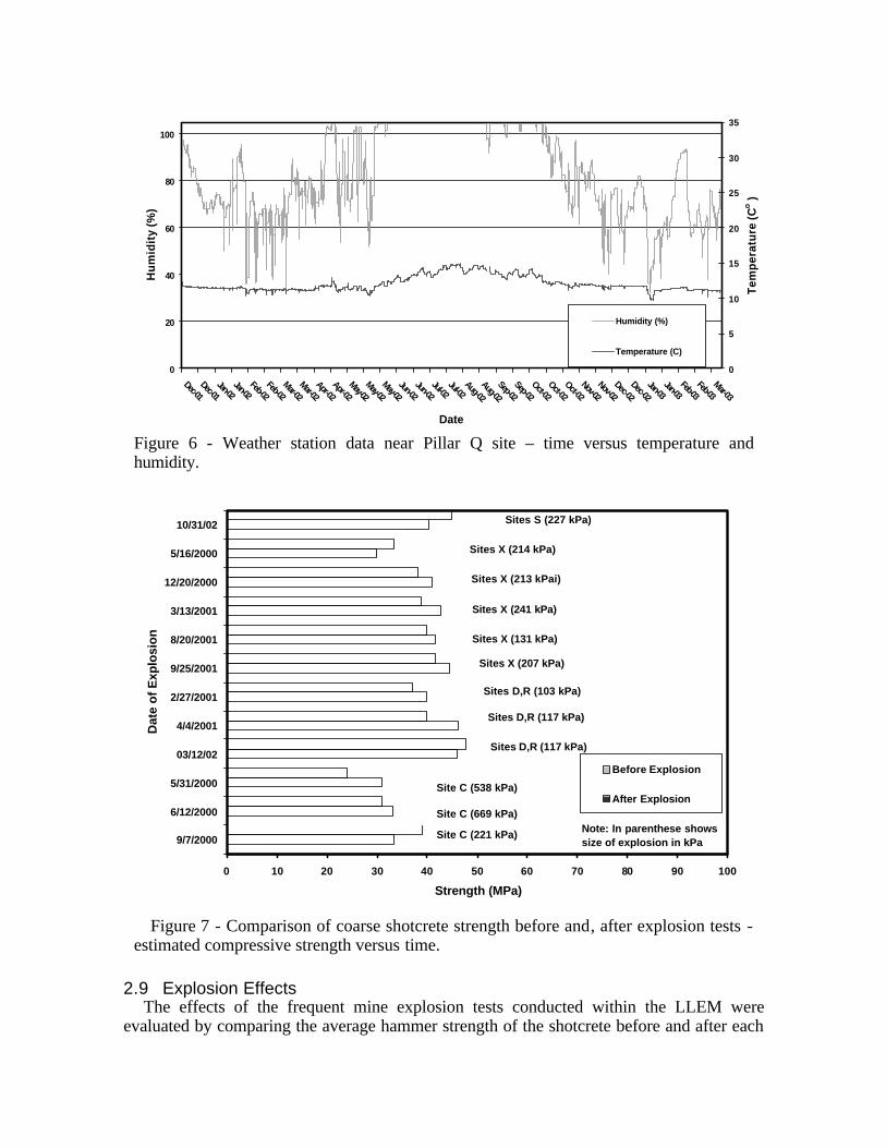
Figure 7 - Comparison of coarse shotcrete strength before and, after explosion tests estimated compressive strength versus time.
2.9 Explosion EffectsThe effects of the frequent mine explosion tests conducted within the LLEM were
evaluated by comparing the average hammer strength of the shotcrete before and after each

explosion test. As can be seen in figure 7, there is no significant decrease in the shotcrete strength. In addition, examinations of the sites before and after each mine explosion testdid not reveal any effects on the physical integrity of the shotcrete. It was apparent after the explosion tests, that the shotcrete had maintained its integrity and stayed completely intact. No fallen roof or rib debris was detected in the areas that were shotcreted. A few areas near site D have scrapings in the shotcrete due to debris hitting the face from explosions tests in the D drift.
2.10 Bedded Shale Effects
Mar-00
May-00
Jul-00 Sep-00
Nov-00
Jan-01
Mar-01
May-01
Jul-01 Sep-01
Nov-01
Jan-02
Mar-02
May-02
Jul-02
Sep-02
Nov-02
Jan-03
0
5
10
15
20
25
30
35
40
45
50
Ave
rage
d St
reng
th (M
Pa)
Limestone Bedded Shale
Date
Figure 8 - Comparison of coarse shotcrete strength in the limestone and bedded shale time versus estimated compressive strength.
Test sites were also established to determine if the shotcrete strength is different on the shale than on limestone surfaces. The preliminary short-term results, as shown in figure 8, do not reveal any significant difference in the shotcrete strength, which appears to indicate that the shotcrete adheres equally well on the bedded shale as it does with the limestone. If the shale binder did not provide a good bond or had detached from the shotcrete, thehammer results would have been significantly lower.
2.11 Bonding Effects Following the shotcrete cure period (greater than 56 days), the shotcrete was sounded
with a geologist’s hammer to indicate isolated areas in the shotcrete that produced a hollow(drummy) sound compared to the solid sound elsewhere. This hollow sound may be the result of an air cavity behind the shotcrete. To determine if cavities behind the shotcrete affects its strength, a representative sample of hollow and solid sounding areas wereevaluated. Figure 9 shows that the hollow cavity areas have 25% lower strength than the solid areas. This trend is fairly consistent through the three year study period. The periodic
Mar-00
May-00
Jul-00
Sep-0
0
Nov-00
Jan-01
Mar-01
May-01
Jul-01
Sep-0
1
Nov-01
Jan-02
Mar-02
May-02
Jul-02
Sep-0
2
Nov-02
Jan-03
0
5
10
15
20
25
30
35
40
45
50
Ave
rage
d St
reng
th (M
Pa)
Solid Hollow
Figure 9 - Comparison of coarse shotcrete strength by bond effects -time versus estimated compressive strength.
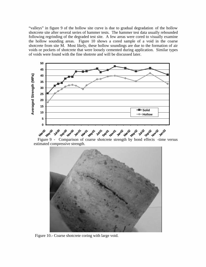
“valleys” in figure 9 of the hollow site curve is due to gradual degradation of the hollow shotcrete site after several series of hammer tests. The hammer test data usually reboundedfollowing regrinding of the degraded test site. A few areas were cored to visually examine the hollow sounding areas. Figure 10 shows a cored sample of a void in the coarse shotcrete from site M. Most likely, these hollow soundings are due to the formation of airvoids or pockets of shotcrete that were loosely cemented during application. Similar types of voids were found with the fine shotrete and will be discussed later.
Figure 10.- Coarse shotcrete coring with large void.

2.12 Fine Shotcrete Fine shotcrete was installed in September 2001 at site Q in A drift. As listed in table 2, a
16% overspray/rebound rate was estimated with the fine shotcrete which was comparable to the coarse shotcrete rate. After 16 months of monitoring its strength using the SchmidtHammer the estimated compressive strength of the fine shotcrete had increased 45% compared to 72% for the coarse shotcrete for the same time period (figure 4 and 11). Figure 3 shows that the initial 56-day strength of the fine shotcrete was higher than coarse shotcrete (29 MPa versus 22 MPa) however, the maximum strengths appear to be similar (42 MPa vs. 43 MPa). According to the manufacturer’s specification sheet, the maximum strength is 55 MPa for the coarse shotcrete and 57 MPa for the fine shotcrete. In addition, the greatest increase in strength for both the coarse and fine shotcrete seems to coincide with the late spring and early summer period, 60% and 35% increase respectively (figure 4 and 11). Perhaps the full curing of the shotcrete (after 56 days) is not so much a function oftime, but rather a function of greatest time exposure to moisture. To date, the fine shotcrete has not shown any signs of deterioration.
Oct-01
Dec-01
Feb-02
Apr-02
Jun-02
Aug-02
Oct-02
Dec-02
0%
5%
10%
15%
20%
25%
30%
35%
40%
45%
50%
Cum
ulat
ive
Perc
ent I
ncre
ase
Date
Figure 11- Schmidt Hammer fine shotcrete results - time versus cumulative percentincrease in strength.
2.13 Sample CoresCores were taken of the in situ fine shotcrete from an accessible site. Several of these
cores were found to have vertical bedded voids, inadequately mixed shotcrete, and shotcrete areas that were poorly bonded to the rib rock. Figures 12-13 show core samples with large vertical voids parallel to the rib face. Figure 13 shows a void that originates from shotcrete that is poorly mixed and cemented together. Perhaps the loosely cemented

aggregate and glass fibers allows the shotcrete to bridge air gaps resulting in narrow vertical voids as each layer is applied.
Figure 12 - Fine shotcrete coring with large void.
Figure 13 - Fine shotcrete coring with voids originating from poorly mixed material.
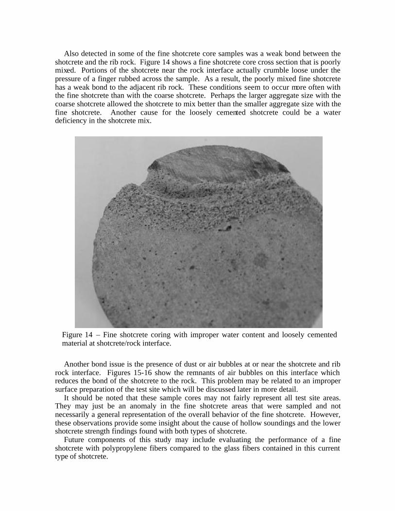
Also detected in some of the fine shotcrete core samples was a weak bond between the shotcrete and the rib rock. Figure 14 shows a fine shotcrete core cross section that is poorlymixed. Portions of the shotcrete near the rock interface actually crumble loose under the pressure of a finger rubbed across the sample. As a result, the poorly mixed fine shotcrete has a weak bond to the adjacent rib rock. These conditions seem to occur more often with the fine shotcrete than with the coarse shotcrete. Perhaps the larger aggregate size with the coarse shotcrete allowed the shotcrete to mix better than the smaller aggregate size with the fine shotcrete. Another cause for the loosely cemented shotcrete could be a water deficiency in the shotcrete mix.
Figure 14 – Fine shotcrete coring with improper water content and loosely cemented material at shotcrete/rock interface.
Another bond issue is the presence of dust or air bubbles at or near the shotcrete and rib rock interface. Figures 15-16 show the remnants of air bubbles on this interface which reduces the bond of the shotcrete to the rock. This problem may be related to an improper surface preparation of the test site which will be discussed later in more detail.
It should be noted that these sample cores may not fairly represent all test site areas.They may just be an anomaly in the fine shotcrete areas that were sampled and not necessarily a general representation of the overall behavior of the fine shotcrete. However, these observations provide some insight about the cause of hollow soundings and the lower shotcrete strength findings found with both types of shotcrete.
Future components of this study may include evaluating the performance of a fine shotcrete with polypropylene fibers compared to the glass fibers contained in this currenttype of shotcrete.

Figure 15 - Fine shotcrete coring with poor bonding at the rock/shotcrete interface due to air pockets and bubbles.
Figure 16 - Fine shotcrete coring with small air bubbles formed at the shotcrete/rock interface.

2.14 Latex/Cement Thin Spray-on Liner The latex/cement thin spray-on liner has been the longest standing material in the study.
It was applied in October 1999 and has performed favorably. A double thickness of 8 mm of spray-on liner material was applied on pillar A in the hydrostatic test chamber area (figure 2) of the mine. In this area, ventilation control structures are frequently evaluatedthrough explosion testing to study failure mechanisms. These explosion tests generate considerable blast vibrations in the area. Over the past 40 years, the pillars in this area have spalled considerably due to weathering as described earlier and more recently due todamage caused by debris propelled at the pillar as the result of the explosion tests. Added stress conditions due to the greater overburden at this site may also be influencing the pillar spalling in this area. To date it appears that despite the severe conditions, the latex/cementliner has effectively sealed the pillar from additional weathering mechanisms. No rock spalling has occurred since application of the liner. Although the liner material does not contribute significant structural support (table 1-2) it may provide some additionalconfinement to the pillar which, in turn, may increase its load carrying capacity.
The latex/cement thin spray-on liner was also applied on a 76 m section of the large barrier pillar (BP1) near the entrance portal (figure 2). This area of the mine is subject tofrequent freeze thaw cycles and large changes in temperature and humidity (figure 5). An 8 mm thick double coating of liner material was applied around a corner area and on the unmeshed areas of the adjacent roof. The liner at this site has also performed well, with theexception of four small patches (approximately 3.7 m2 total area) that have detached from the rib. These patches represent less than 1% of the total area covered. Upon close observation, it appeared the cause of failure was more related to the failure of the rock thanfailure of the liner material. In three of the cases, the area was located at the bedded shale material near the rib/roof corner. Most likely, the fractured shale was partially degraded when initially sealed. Close examination of the detached liner material indicates that the dominant failure mechanism was the rock failing and not the liner material. However, the weight of the loose rib rock eventually exceeded the strength of the liner (which in two of the cases was a single thickness of 4 mm), allowing a section to tip and fall from the rib. If this site had been properly scaled and the damaged rock removed, in all probability the latex/cement liner would not have detached.
2.15 Methacrylate-Based Thin Spray-on Liner Several different experimental versions of the methacrylate-based thin spray-on liner
were installed on small trial areas at sites L and E (figure 2) in 2001 and 2002. The liner trials that did not perform adequately were removed and the methacrylate formulation was adjusted for the next trial. Several adjustments were made to the formulation to decrease the viscosity and improve its tolerance to moisture. Pump and application problems werecorrected to provide a more uniform thickness of the spray-on liner to the mine ribs.
The reformulated methacrylate thin spray-on liner was applied to three different types of surface conditions at the site L. The first was a test surface that had been previouslycoated with an earlier methacrylate-based thin spray-on liner that did not mix and set properly. A portion of the un-reacted liner material on this surface was removed from the rib however, a considerable amount of material remained. Application of the reformulatedmethacrylate material over the un-reacted material did not provide a good base for adherence. After a few days, most of the new application debonded from the mine wall. At the second L site, a surface that had been scaled and then saturated with water without drying the surface was evaluated The reformulated methacrylate material debonded from the saturated mine wall, due to the excess water on the rock surface. At the third site, the

surface that had been scaled and then blown dry was evaluated. In this case, with the surface moist but with no excess water on the rock surface, the reformulated methacrylate material performed well. In a few minor areas where the reformulated methacrylate liner was applied in a very thin coating, some debonding occurred. After four months of application, the reformulated methacrylate-based thin spray-on liner continues tosufficiently seal the mine rib and prevent the rib from deterioration.
2.16 Polyurea Thin Spray-on LinerA polyurea liner material was installed in April 2002 at sites K and F. The rib face was
scaled and washed before application of the three layers of polyurea. Both test sites had small trial areas where the face was not washed and areas that were saturated with water. After nearly a year of application, it does not appear that these trial areas were adversely affected by the dirt or moisture.
At the site F, three trial areas were established without applying the initial primer layer.In the first area, only the second and third layer of polyurea was applied. In the second
area, only the second layer of polyurea was applied. In the third area, only the third layer of polyurea was applied to the unprimed rib rock. After nearly a year of application, onlythe second layer (web layer) showed some areas of debonding. The other trial areas appear to be unaffected with the absence of the primer layer. The remaining areas of the site F appear to be securely sealed.
2.17 MDI Exposure Evaluation The polyurea “A” component contains diphenylmethane diisocyanate (MDI), which can
be a powerful irritant to the respiratory system. According to the Coal Mine Health Inspections Procedures Manual (MSHA, 2003), workers exposed to isocyanate foams can become sensitized, making them subject to severe asthma attacks if they are re-exposed,even at low concentrations. To address these concerns, the Mine Safety Health Administration (MSHA), Physical and Toxic Agents Division were contacted to monitor the MDI concentration levels during the application of the polyurea liner material. MSHA used five midget impingers with 20 mL of solution (NIOSH Method #5522) with sampling pumps to sample the air (both vapor and droplets) at both application sites. Figure 17, shows the placement of the impingers relative to the pillar.
According to the MSHA report (Arnold, et al., 2002), the sample analysis showed a nearly unquantifiable concentration of airborne MDI present during and following the application of the polyurea (figure 17). All of the measured concentrations were well below the MSHA ceiling value of 0.2 mL/m3 or 20 ppb. Sixteen of the nineteen samples taken showed no measurable MDI. The first set of readings (readings noted on figure 17 adjacent to the test sites) monitored the application of the polyurea primer and web layersand the second set of readings monitored the application of the final coating. The samples that showed some presence of MDI were mostly located downwind or near the rib during the application of the first two layers at site F. These very low but measurable levels areassociated with the polyurea primer and web layers that were applied to site F. Perhaps, the primer layer may be responsible for these readings since this material is atomized longer in the air than the web layer. At site K, no measurable MDI were detected for any of thepolyurea layers applied.
Although, the air sampling results showed that all MDI concentrations were well below the MSHA ceiling value in the work area and downwind, workers applying the polyurea should follow the respirator requirements detailed in the MSDS (1999). A positive pressure supplied respirator with full face-piece or hood or self contained apparatus is required for

MDI concentrations less than 250 ppb. A NIOSH type C respirator, self contained or supplied positive, demand or continuous flow is required for MDI concentrations greater than 250 ppb.
Figure 17 - Diagram of sampling locations and MDI concentration levels at the F and K sites during the polyurea installation (not to scale).
3 CRITICAL PRACTICES The shotcrete and thin spray-on liner materials are only as strong as their weakest link.
The physical properties of these materials are severely diminished if they are not properlyinstalled. The direct experience gained while working with these materials as well, as numerous discussions with manufacturers (Spearing and Champa, 2001; Browning, 2002; Degville, 2002) and mining personnel (Espley, et al., 2001; Espley, et al., 2001;), indicate that the following critical practices should be carefully considered before using any type of shotcrete or thin spray-on liner material.
3.1 Surface Preparation Probably the most critical and most overlooked component that may hinder the
successful application of a shotcrete or thin spray-on liner material is the surface preparation prior to application. For the LLEM study, the rib and roof were scaled the day before application and washed (689-1,034 kPa water pressure) the day of application. The scaling removes most of the loose material and provides a clean surface for the shotcrete to adhere. Washing the site with water removes most of the smaller size broken rock and dust

that coats the rib and horizontal ledges. A recent study by Kuchta (2002) found an increase in the shotcrete adhesion strength by a factor of four on a concrete wall cleaned with waterat 21 MPa as compared to surface cleaned at 689 kPa. If diesel equipment is operated in the area, a high water pressure cleaning may be capable of removing the slick diesel soot or any oil that may have accumulated on the rib and roof. The Colorado School of Mines included LLEM as a test site for their field study of high pressure water treatment of shotcrete.
3.2 Mine Conditions In the selection of an effective liner material, several questions need to be considered to
fit the needs of the mine. How long must the liner material perform; i.e., what is theanticipated life of the site? Generally, if it is a temporary site, a lower strength liner material can be used with a minimum thickness. If it is a critical site that may play a long-term role in the life of the mine, for example the main beltway, a high strength materialwith a greater thickness than is typically used may be appropriate.
If shotcrete is being installed during the drier winter months, it appears to be beneficial to spray water on the shotcrete on a consistent basis after application. According to thepreliminary results from the LLEM study, shotcrete applied during the winter mo nths increased in strength by 35-60% (figure 4 and 11) during the following summer possibly due to the high humidity that may enhance the curing process and result in the addedshotcrete strength. Humidity levels at the LLEM during the summer months are typically over 100% which produce condensation on the rib and roof of the mine. This seems to indicate that spraying the shotcrete with water may help to better cure the shotcrete to reachits maximum strength.
Not one of the thin spray-on liner or shotcrete materials will perform adequately when applied under flowing water conditions. Flowing water will prevent the material fromproperly curing and adhering to the rock. The source of the water should be identified, diverted, drained, and the substrate relatively dry before any liner material applications.
3.3 Logistical Issues Critical logistical issues that may hinder the effectiveness of the support liner materials
include the proper conditions for storing and applying the material. Most of the liner materials specify a storage temperature range of 4-43° C, however, some polyurethane materials require a minimum storage temperature of 20° C. In addition, all of the materials specify dry storage conditions, especially the shotcrete. Maintaining dry conditions may be difficult to control especially if the materials are stored underground. In mines of limited mining extent, such as LLEM, there are large fluctuations in humidity as shown in the humidity charts (figures 5-6), which can result in condensation. The liner materials should be stored in heated warehouses until required underground and then tarps and shrink wrap should be used to protect the material from condensation.
Another critical factor is tracking the shelf life of the materials. While shotcretes have an indefinite shelf life (if kept in a warm and dry location), most thin spray-on liner materials have a shelf life of just 3 to 6 months. Materials that exceed the shelf life may have a reduced strength.
Finally, the project conditions may affect the curing and bonding of the liner to the rock surface. Some specifications for shotcrete require the surface temperature of the rock be greater than 9° C. In addition, the shotcrete should not be exposed to temperatures below 9° C for a minimum of 96 hours after application. During some of the summer months, areas in close proximity to intake air in many mines experience nearly 100% humidity

which may seriously affect the curing and bonding of some thin spray-on liner materials. The temperature and humidity levels of the application site need to be considered when scheduling the thin spray-on liner and shotcrete work.
3.4 Human Factors Also critical to the performance of the shotcrete is the experience and technique of the
nozzleman installing the material. The basic technique for the LLEM application involved keeping the nozzle perpendicular and maintaining the nozzle approximately 1 m distantfrom the rock surface. According to Browning (2002), the art of shotcreting is building up the proper thickness of shotcrete on the rock at the optimum rate so it adheres but not so fast so that it starts to rebound. Applying shotcrete to the roof is even more difficult due tooverspray and rebound of the shotcrete. Rispin and Brooks (2001) mentions that there are industry wide training programs for nozzlemen, as well as other associated positions, that offer a blend of practical and theoretical knowledge and the importance of properplacement of the shotcrete. Usually application of thin spray-on liner material is not quite as challenging as shotcrete due to shotcrete’s denser consistency and sensitive application process. Critical issues for thin spray-on liner material application are maintaining a proper thickness so that the liner will cure properly and obtaining the proper pump mixing ratios of the two components.
Some other factors that may indirectly benefit the nozzleman’s performance include:• providing the optimal airflow to minimize dust; • using additional lighting to enhance visual attention to ensure proper material adherence
and thickness; • using the required personal protective equipment including a fitted respirator (according
to MSDS specifications); • providing hearing protection;• providing disposable water/chemical resistance coveralls, gloves, and boots; and • following the recommended maintenance and replacement schedules for the nozzle and
other parts of the liner material application equipment.
4 CONCLUSIONS An ongoing study of various types of thin spray-on liner and shotcrete materials at
NIOSH’s LLEM is providing a unique forum for evaluating the long-term behavior of liners in an underground environment. Preliminary results indicate that the latex/cement performed favorably, with less than 1% of the material surface area debonded from the mine rib three years after application. After several trials, a reformulated experimental methacrylate provides a competent seal to prevent weathering on pillars that are relatively dry. The three layer polyurea system provides a durable bond to the pillar and appears to work well even under saturated conditions. In addition, the MDI monitoring of polyurea found that these levels are very low or undetectable.
The coarse and fine shotcrete have performed favorably over the study period. Althoughno observations of shotcrete failure occurred to date during the study, several areas indicated an incomplete bond with the rock according to the results obtained from the Schmidt Hammer tests. The hollow sounding areas in the coarse shotcrete resulted in 25% lower compressive strengths. Sample corings indicate these hollow sounding areas may be related to voids, poor mixing, water deficiency in the mix, and/or air bubbles in the shotcrete. Hammer test results indicate that the shotcrete strength does not seem to be affected by the bedded shale or vibrations induced by the experimental explosion tests. However, a delay in the full curing process appeared to have occurred for both types of

shotcrete. Full curing was not achieved until the humid summer months. Then a 35-60% increase in the shotcrete strength was achieved as documented by the Schmidt Hammer testresults. Humidity levels at the LLEM during the summer months are typically over 100% which produces condensation on the rib and roof of the mine which may promote the shotcrete reaction and additional strength.
Other critical practices that need to be addressed specifically include proper surface preparation of the mine strata prior to application. A clean surface that is devoid of loose rocks, dust, or diesel soot ensures a good bond with the thin spray-on liner or shotcrete materials. Additional critical practices are related to the mine conditions, logistical issues, and human factors.
With the emerging technology of thin spray-on liner materials, more U.S. mines arestarting to use these materials to rehabilitate critical underground locations afflicted with weathering and unraveling ground conditions. The use of these liner materials is expected to reduce the occurrence of groundfalls which will provide an additional tool to enhance worker safety and extend the longevity of the underground workings. In the not too distant future, both shotcrete and thin spray-on liner materials may be used in the underground metal mi nes as the primary ground control component during the mining development cycle. Perhaps segments of this technology may be applied to underground coal mines and provide a partial solution to reducing the high number of roof and rib fall injuries during face development.
REFERENCES American Society for Testing and Materials (2001) Standard test method for rebound
number of hardened concrete, C 805-97 in 2001 in Annual Book of ASTM Standards. Sec. 4, Vol. 04.02, Concrete and Aggregates. Philadelphia, PA. pp. 416-418.
Archibald J., and DeGagne D. (2001) Spay-on lining support in canadian underground mining- a research summary, CIM Bulletin. Vol. 94, no. 1050. pp. 49-56.
Arnold, E., Mewa, P., and Valoski, M. (2002) Industrial hygiene field investigation rock web mine roof and rib support adhesive, U.S. Department of Labor, Mine Safety and Health Administration, IR PP-001-03O.
Baiden, G. (1999) Telemining systems applied to hard rock metal mining at inco limited, Proceedings from the 2nd International Conference on Intelligent Processing and Manufacturing of Materials. Honolulu, HI. Vol. 2. pp. 53-58.
Beaupre, D. (1994) Underground shotcrete quality assessment, Centre de Recherche Interuniversitaire Sur Le Beton. Laval University, Montreal, Quebec. December. 21 pp.
Browning, A. (2002) Personal Conversation. Degville, D. (2002) Personal Conversation. Espley, S., Gustas, R., Heilig, H., and Moreau, L. (2001) Thin spray-on liner research and
field trials at INCO, Australian Center for Geomechanics, International Seminar on Mine Surface Support Liners 2001: Membrane, Shotcrete and Mesh. Perth, Australia. Sec. 25. pp. 1-23.
Espley, S., Malek, F., and O’Donnell, J. (2001) INCO’s experience with shotcrete for ground support, Australian Center for Geomechanics, International Seminar on Mine Surface Support Liners 2001: Membrane, Shotcrete and Mesh. Perth, Australia. Sec. 9. pp. 1-22.
Kuchta, M. (2002) Quantifying the increase in adhesion strength of shotcrete applied to surfaces treated with high pressure water, SME Annual Meeting. Phoenix, AZ. SME preprint 02-035. 4 pp.

Molinda, G., Dolinar, D., and Robertson, S. (2002) Reducing injuries from the fall of roof in u.s. coal mines, Unpublished paper presented at the Society for Mining, Metallurgy, and Exploration, Inc. (SME), Annual Meeting and Exhibit. Phoenix, AZ. February 2527, 2002.
MSHA (2003) Polyurethane foam, In: Coal Mine Health Inspection Procedure Handbook.Washington, DC: U.S. Department of Labor, Mine Safety Health Administration. PH89V-1. pp. 9.1-9.9.
Pappas, D., Barton, T., and Weiss, E. (2002) Developments in sealant support systems for ground control, Proceedings from the 21st International Conference on Ground Control in Mining. Morgantown, WV. August 6-8. pp. 344-353.
Rispin, M. and Brooks, J. (2001) Shotcrete in North American underground mines:yesterday, today and tomorrow, CIM Bulletin. Vol. 94, no. 1052. pp. 76-79.
Rispin, M., Runciman, N., and Knight, B. (1999) Shotcrete research and development at INCO’s test mine, Proceedings of the 3rd International Symposium on Sprayed Concrete:Modern Use. Oslo, Norway. pp 430-438.
Spearing, A. and Champa, J. (2001) Superskins - the present and the future, Australian Center for Geomechanics, International Seminar on Mine Surface Support Liners 2001: Membrane, Shotcrete and Mesh. Perth, Australia. Sec. 16. pp 1-11.
Spray-On Plastics (1999) Material safety data sheet for Rock Web system “A”. Triebsch, G. and Sapko, M. J. (1990) Lake Lynn Laboratory: A state-of-the-art mining
research facility, Proceedings of the International Symposium on Unique Underground Structures. Denver, CO. June 12-15. CSM Press, Vol. 2. pp. 75-1 to 75-21