Embed Size (px)
Citation preview

The programming Projects
Student Book
Third Secondary
Unit Two
General Directory for Developing the Subject of Computer & Information
Technology
Developing Curriculums and Educational Subjects Center
2017/2016

1
Information and communication
Technology The Programming Projects
Third Secondary Second Term – Student Book
Prepared by
Dr.Taher Abdelhamid Eladly Computer and Information Technology
Curricula Expert and Head of Department Centre For Curriculum &Instructional Materials
Development
Eng. Wassim Salah Eldeen El Manzalawy
Department Director
General Administration for Computer & Information Technology Development
Mr. Tamer Abdelmohsen Mansour Department Director
General Administration for Computer & Information Technology Development
Mr. Ahmed El Anasari ElSalamoni Department Director
General Administration for Computer & Information Technology Development
Educationally revised by
Dr.Rougina Mohamad Hegazy Expert in Centre For Curriculum & Instructional Materials Development
Technically revised by
Ms Mashaallah Mohamad Mohammad Computer and Information Technology Curricula Expert Computer
Prof. Mohamad Fahmi Tolba Computer and Information Technology Prof
Ain Shams University
2
Designed by
Ms Abeer Mohamad Anwar Mohamad Department Director
General Administration for Computer & Information Technology development
Translated by
Dalia Hassen Mohamed Mahmoud
Educational specialist of English language
Office of the development of the English language
material director
Amira Fawzy Ahmed
Head of Foreign Languages Department
Centre for Curriculum & Instructional
Materials Development
Technical Terms
Dr Amany Korany Ibrahim General Manager
General Administration for Computer and Information Technology Development
Eng. Wassim Salah Eldeen El Manzalawy Department Director
General Administration for Computer & Information Technology Development

3
Second Unit Producing a project of logic gates simulation
Information and Communication Technology – Third Secondary
Introduction
This book presents a comprehensive vision of the relationship between
science, technology and society, which reflects the role of information and
communication technology and its innovations in various fields of life and
community development, through training students on the skill of the
implementation of some software projects based on the Markup language
HTML, programming languages PHP &VB.NET and applications such as
Expression Web.
Those projects help students practice many of the technological skills and
conscious behaviors by using information and communication technology, in
addition to the development of their multi positive attitudes.
The first unit of the book deals with implementation of a project to convert
a number between the numerical systems programmatically, and this unit
includes a simplified explanation of numerical systems as a cognitive basic
background, followed by display the unit topics that represent the stages of
implementation of the project, and the implied skills that the students have to
train on.
The second unit deals with the Logic Gates which is considered the basics
for the electronic integrated circuits and it represents the basics for the
computer and electronic devices, and how it performs through applied projects
production which stimulate it, with showing some life applications to employ the
idea of Logic Gates, by considering life decisions as a set of issues or
mathematical formulas which can be evaluated and judged right or wrong ,
which is considered a lifestyle and style of thinking which helps in taking life
decisions in a scientific method, which represents a very important input to
qualify you, dear student, for your future life, and qualification towards the
specialized study in this field.
GOD GRANTS SUCCESS
STAFF

4
Second Unit Producing a project of logic gates simulation
Information and Communication Technology – Third Secondary
Table of contents
page number Subjects
6 Unit two: Producing a project of the logic gates simulation
10 First subject: The logic AND gate
19 Second subject: Producing a project of the logic gate simulation AND by using visual basic.net
32 Third subject: Producing a project of the logic AND gate simulation by using PHP Enrichment only for the academic year 15 _ 16
40 Forth subject: The logic OR gate
48 Fifth subject: Producing a project of the logic OR gate simulation
60 Sixth subject: Producing a project of the logic gate OR simulation by PHP language
Enrichment only for the academic year 15 _ 16
65Sevens subject: The logic NOT gate
71 Eighth subject: Producing a project of the logic NOT gate simulation.................61
78 Ninth subject: Producing a project of the logic NOT gate simulation.by PHP language.............. Enrichment only for the academic year 15 _ 16
82 Tenth subject: Employing the logic gates in taking life decisions
5
Second Unit Producing a project of logic gates simulation
Information and Communication Technology – Third Secondary
Aims of INFORMATION & COMMUNICATION TECHNOLOGY book for Third-grade general secondary: Acquiring some basic concepts and processes for computer systems
and information and communication technology basics.
Taking into account certain aspects of Intellectual Security (human,
moral and social life) that are concerned with the use of Information &
Communication Technology.
Using the technological production tools (Visual Basic .Net &
PHP............) in supporting and developing education.
Producing work and projects that is relatively creative by using
technological processes, programs and tools.
Employing technological communication tools in communication,
interaction, cooperation and exchange of content and insights with
others, in order to support learning.
Using technological (tools and resources) in data processing, evaluating
and reporting the results.
6
Unit two
Information and Communication Technology – Third Secondary
Unit two Producing a project of the logic gates simulation
By the end of the unit students will be able to:
1- Recognize some scientific concepts and terminology related to the
computer (Programming Languages - The logic gates AND-OR-NOT).
2- Suggest simple projects for the logic gates simulation (AND&OR&NOT).
3- Employ information and communication technology applications in the
construction of his educational content and development of its tasks.
4- Practice programming skills PHP&VB.NET in performing his tasks.
5- Follow the ethics and behaviors of respect for copyrights when dealing
with information, devices, networks, services and web applications.
6- Employ interactive learning environments in his learning.
7- Employ the logic gates to solve some life and educational problems.
8- Use the information and electronic data in the performance of research
and educational tasks in partnership with his classmates.
9- Employ the technological tools and resources in supporting making life
decisions.

7
Unit two
Information and Communication Technology – Third Secondary
The logic gates
Introduction Dear students, after the implementation of a project of a program to
convert a number between the numerical systems, we start together to
implement several projects to produce software to simulate some of the
logic gates ,which requires you to be aware of some of the concepts and
knowledge which is considered its cognitive base.
This unit deals with the concept of Logic (gates and circuits) and
their kinds, and their related applications and uses in our daily lives, and
how it can be produced. These subjects reflect the role of the logic gates in
taking many decisions .and especially daily life decisions.
The concept of "logic" refers to the correct thinking rules which we
follow to judge right or wrong issues or mathematical formulas.
In addition, the logic gates are the entry point for university study
specialized in this field.
8
Unit two
Information and Communication Technology – Third Secondary
Before dealing with subjects of this unit, we should recognize
the following:
The idea of the work of a lot of electronic devices depends on the
use of logic circuits to perform the basic processes that are performed in a
frequently, accurately and very high speed aspect.
The Logic Circuit The logic circuits consist of a number of components which are
called logic gates; the logic gate is a simple electronic circuit that has one
INPUT or more and only one OUTPUT.
Based on the availability of certain conditions in the inputs, the
value of the output is determined, and thus it can be considered as it
implements a logical process.
There are many Logic gates which is differ in its function according
to its design.
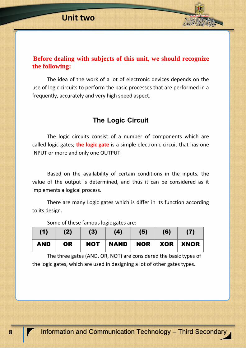
Some of these famous logic gates are:
(1) (2) (3) (4) (5) (6) (7)
AND OR NOT NAND NOR XOR XNOR
The three gates (AND, OR, NOT) are considered the basic types of
the logic gates, which are used in designing a lot of other gates types.

9
Unit two
Information and Communication Technology – Third Secondary
XOR
10
Unit two
Information and Communication Technology – Third Secondary
Learning outcomes
At the end of this subject, learner should have the ability to:
Explain the logic AND gate.
Discuss the compatibility gate symbol with his classmates.
Design possibilities table of the effect of the two input switches
state on the output.
Explain The Truth Table of AND gate.
The logic AND gate
11
Unit two
Information and Communication Technology – Third Secondary
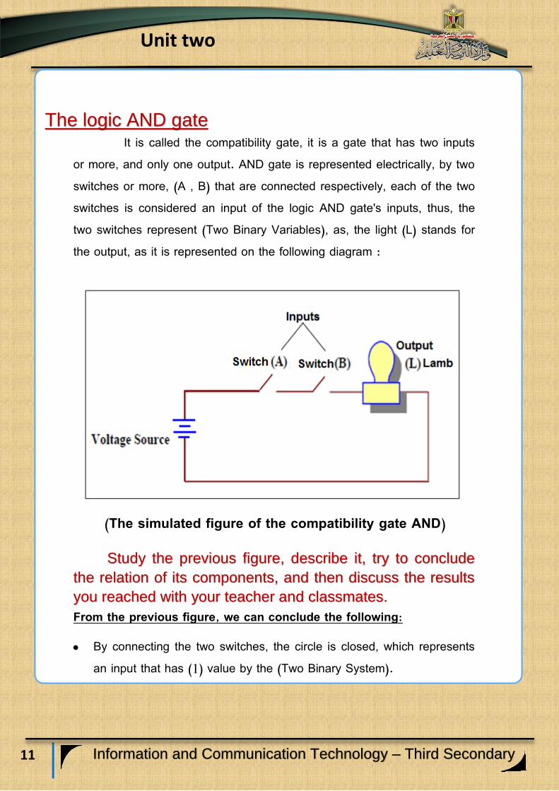
The logic AND gate It is called the compatibility gate, it is a gate that has two inputs
or more, and only one output. AND gate is represented electrically, by two switches or more, (A , B) that are connected respectively, each of the two switches is considered an input of the logic AND gate's inputs, thus, the two switches represent (Two Binary Variables), as, the light (L) stands for the output, as it is represented on the following diagram :
(The simulated figure of the compatibility gate AND)
Study the previous figure, describe it, try to conclude
the relation of its components, and then discuss the results
you reached with your teacher and classmates.
From the previous figure, we can conclude the following:
By connecting the two switches, the circle is closed, which represents an input that has (1) value by the (Two Binary System).

12
Unit two
Information and Communication Technology – Third Secondary
By disconnecting any switch, the circle is opened, so, this represents an input that has (0) value by the (Two Binary System), i.e. the value of any switch that leads to opening the circle is equivalent to (0).
Lighted light means that the output value equivalent (1). The non-lighted light means that the output value equivalent (0).
Discuss with your classmates and your teacher the results you get, and match it with the following diagram:
The question now is: What are the possibilities of the two switches state (A, B) and their effect on the electric light (L) state?
Practice (1) "The circuit that is equivalent to the
logic AND gate”
Activity book (p: 5)

13
Unit two
Information and Communication Technology – Third Secondary
Table (1) The possibilities of the two switches state (A, B) and their
effect on the electric light (L) state.
A B L
OFF OFF NON -
LIGHTED
OFF ON NON -
LIGHTED
ON OFF NON -
LIGHTED
ON ON LIGHTED

14
Unit two
Information and Communication Technology – Third Secondary
The logic AND gate symbol
The following symbol represents the logic AND gate that has two
binary inputs, study the code, describe it, and then, discuss with
your classmates and your teacher.
AND gate symbol (two binary inputs)
By studying the logic AND gate symbol, it is cleared
that:
(A, B) refer to the inputs of AND gate, and (L) refers to the
output of the gate.
The gate's input that is on the left side of the symbol
includes the value of all the input possibilities, as it
expresses the input as (two binary numbers) (0,1), on the
other hand, the output is on the right side (binary numbers)
also.

15
Unit two
Information and Communication Technology – Third Secondary
Number of forms (possibilities)
Each of the logic gates has a number of forms or possibilities that is accounted by knowing the number of inputs of
the logic gate by the following law: N = 2n
As, N refers to number of forms, the (2) number refers to the binary system base, that we use as a value of the gate's input (0,1), and (n) refers to the number of the gate's input. For example: AND gate (two binary inputs), its forms number is:
N = 22
= 4
If the AND gate has triple inputs, its number of forms or possibilities are:
N = 23
= 8
On the same pattern, you can calculate the number of forms or possibilities of any logic gate. The Truth Table
It is a table which helps in explanation of the logic gate behavior, taking into account, the relation between the input and the output of the Logic gate.
16
Unit two
Information and Communication Technology – Third Secondary
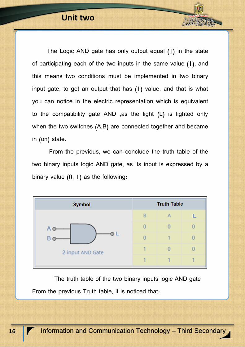
The Logic AND gate has only output equal (1) in the state of participating each of the two inputs in the same value (1), and this means two conditions must be implemented in two binary input gate, to get an output that has (1) value, and that is what you can notice in the electric representation which is equivalent to the compatibility gate AND ,as the light (L) is lighted only when the two switches (A,B) are connected together and became in (on) state.
From the previous, we can conclude the truth table of the two binary inputs logic AND gate, as its input is expressed by a binary value (0, 1) as the following:
The truth table of the two binary inputs logic AND gate
From the previous Truth table, it is noticed that:

17
Unit two
Information and Communication Technology – Third Secondary
By considering that any input is a condition, if the two conditions (1) are achieved in the logic AND gate, it leads to getting the output.
The output in AND gate= (1) just when all the inputs equal the value (1).
The Boolean formula of the logic AND gate
The Boolean algebra is considered a formula of logistic that shows how logic gates work. The Boolean expression is a brief method in order to show what is happening in any logic circuit, the following Boolean expression represents the AND gate that has two inputs and it is expressed with two formulas :
Y = A . B Or Y = AB
This is called “Logical Multiplication”, We can express it as the following:
Practice (2) Forms (possibilities) of the output of
the logic AND gate and the truth table
Activity book (p: 6)

18
Unit two
Information and Communication Technology – Third Secondary
The output Y is equal to A AND B
We can summarize what is mentioned before in the following table:
Statement Representation on the AND gate
The gate's
name
AND
The logic
symbol -
standard- of
the gate
The number of
forms
We can calculate the number of possibilities that
forms the truth table of the gate of the two binary
inputs by the following law:
N = 2n
N = 22
= 4
The truth table
The Boolean
formula of the
gate
Y = A. B OR Y = AB
An Expression of the Boolean formula of the gate
AND that has two inputs.
Table (2) the AND gate summary

19
Unit two
Information and Communication Technology – Third Secondary
Learning outcomes:
By the end of this subject learner should have the ability to:
1. Determine the stages of producing a project of the logic AND gate simulation by using the Visual Studio.Net application.
2. Design the interface of the project of the logic AND gate simulation.
3. Use the Visual Studio.Net application to build up the interface of the project, explaining the controls.
4. Explain the used programming code in the project of the logic AND gate simulation.
5. Employ the code of the project implementation practically.
Producing a project of the
logic AND gate simulation
20
Unit two
Information and Communication Technology – Third Secondary
The project purpose
Producing a program to simulate the logic AND gate.
The project production requirements:
1- The scientific background of the logic gate AND, and that is what is studied before.
2- Determination of the programming language that you can use in the project production, you can make use of what is previously studied and employ your experience and your skills in Visual Basic.Net and PHP languages.
Implementation of the project procedures:
1- Designing the interface that the user uses for the project "Graphic
User Interface" GUI, and determining the suitable controls for each use
of the project implementation in a suitable aspect.
2- Adjusting controls’ properties in view of the necessary needs of the
project production.
3- Writing the programming code.

21
Unit two
Information and Communication Technology – Third Secondary
The stages of the project production:
Firstly: The designing stage
Dear student, you can design the interface of the project that is
based on your desires, and include controls on it, to achieve your aim of
simulating the (connect/disconnect) switch of turning on the electric light
process. The following figure is a proposal of designing the form window
and its necessary controls to produce the project.
By studying the components and the elements of the previous
form, we can conclude controls on the form window and the
aim of each of them, and it is obviously shown in the following
table:
22
Unit two
Information and Communication Technology – Third Secondary
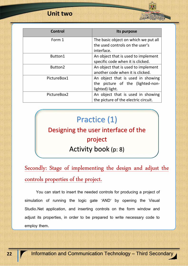
Control Its purpose
Form 1 The basic object on which we put all the used controls on the user's interface.
Button1 An object that is used to implement specific code when it is clicked.
Button2 An object that is used to implement another code when it is clicked.
PictureBox1 An object that is used in showing the picture of the (lighted-non-lighted) light.
PictureBox2 An object that is used in showing the picture of the electric circuit.
Secondly: Stage of implementing the design and adjust the
controls properties of the project.
You can start to insert the needed controls for producing a project of simulation of running the logic gate "AND" by opening the Visual Studio.Net application, and inserting controls on the form window and adjust its properties, in order to be prepared to write necessary code to employ them.
Practice (1) Designing the user interface of the
project
Activity book (p: 8)

23
Unit two
Information and Communication Technology – Third Secondary
Thirdly: Writing the programming code stage:
Before starting writing the project code, try to suggest the possible results of the project code implementation according to the light state (the output), we can show its four possibilities in the following table:
- The first light state is: Off
- The second light state is: Off
- The light picture : non-lighted
- The first light state is: On
- The second light state is: On
- The light picture : lighted
Activity (1)
"Designing the user's interface
implementation by using
(Visual Studio. Net) application"
Activity book (p: 9) (The procedures from 1:3)

24
Unit two
Information and Communication Technology – Third Secondary
- The first light state is : Off
- The second light state is : On
- The light picture : non-lighted
- The first light state is : On
- The second light state is : Off
- The light picture : non-lighted

25
Unit two
Information and Communication Technology – Third Secondary
Observations:
The idea of code is summarized as follows:
Determining an object or more that is responsible for the code
implementation when a certain event occurs on the object, and in the
project, a code can be written in the following objects:
Form object (Form1_load event):
To show the non-lighted light image in picturebox1. To show the electrical circuit image in pocturebox2. To show the two buttons in (Off) state.
Button1 object:
By pressing click on it, the code tests the switch state and changes it between (on- off).
Then, testing the first and second switches state, and changing the light image into the suitable correct state for the two power switches state.
The button state is changed between "On" and "Off" by pressing on Click.
Finding two pictures in two different files of the light, one of them is lighted and the other is non-lighted, are shown in the same place of the PictureBox1 tool depending on the instructions of the programming code.

26
Unit two
Information and Communication Technology – Third Secondary
Button 2 Object:
By pressing click on it, the code tests the switch state and changes it between (On- Off).
Then, testing the first and second switches state, and changing the light image into the suitable correct state for the two switches state.
Writing the specific code of each object from the previous
three objects and this is through:
A code you prepared. Or
Searching the internet for a code that could do the mission and it can be altered or developed as your project requires.
Or By using a ready function that is afforded by the programming
language which you use.
In a project of operating the logic gate AND simulation, we will study and explain the used code through the specific code of the book, its effect appears on the light state , whether it is lighted or non-lighted, according to the two switches state “On or Off” after pressing Click on the two switches.
Dear student, you can study and explain the next code, it is divided into three parts to facilitate its study:

27
Unit two
Information and Communication Technology – Third Secondary
Private Sub Form1_Load(ByVal sender As Object, ByVal e As
System.EventArgs) Handles Me.Load
Me.PictureBox1.Image = Image.FromFile("off.jpg")
Me. PictureBox2.Image = Image.FromFile("andcircuit.jpg")
Me.Button1.Text = "Off"
Me.Button2.Text = "Off"
End Sub
Private Sub Button1_Click(ByVal sender As System.Object, ByVal e As
System.EventArgs) Handles Button1.Click
If Me.Button1.Text = "Off" Then
Me.Button1.Text = "On"
If Me.Button2.Text = "On" Then
Me.PictureBox1.Image = Image.FromFile("on.jpg")
End If
Else
Me.Button1.Text = "Off"
Me.PictureBox1.Image = Image.FromFile("off.jpg")
End If
End Sub
Private Sub Button2_Click(ByVal sender As System.Object, ByVal e As
System.EventArgs) Handles Button2.Click
If Me.Button2.Text = "Off" Then
Me.Button2.Text = "On"
If Me.Button1.Text = "On" Then
Me.PictureBox1.Image = Image.FromFile("on.jpg")
End If
Else
Me.Button2.Text = "Off"
Me.PictureBox1.Image = Image.FromFile("off.jpg")
End If
End Sub
First
part
Second
part
Third
part

28
Unit two
Information and Communication Technology – Third Secondary
Code explanation:
The first part:” setting the default state of the circuit “
Private Sub Form1_Load(ByVal sender As Object, ByVal e
As System.EventArgs) Handles Me.Load
Me.PictureBox1.Image = Image.FromFile("off.jpg")
Me. PictureBox2.Image = Image.FromFile("andcircuit.jpg")
Me.Button1.Text = "Off"
Me.Button2.Text = "Off"
End Sub
Its purpose is:
Giving the role of the programming code to form1 in load event, to be implemented when loading the form window, where:
The non-lighted light image is specified from “off.jpg” file to PictureBox1.
The circuit image is specified from “circuit.Jpg” to PictureBox2.
Showing button1 and button2 switches in off state.
29
Unit two
Information and Communication Technology – Third Secondary
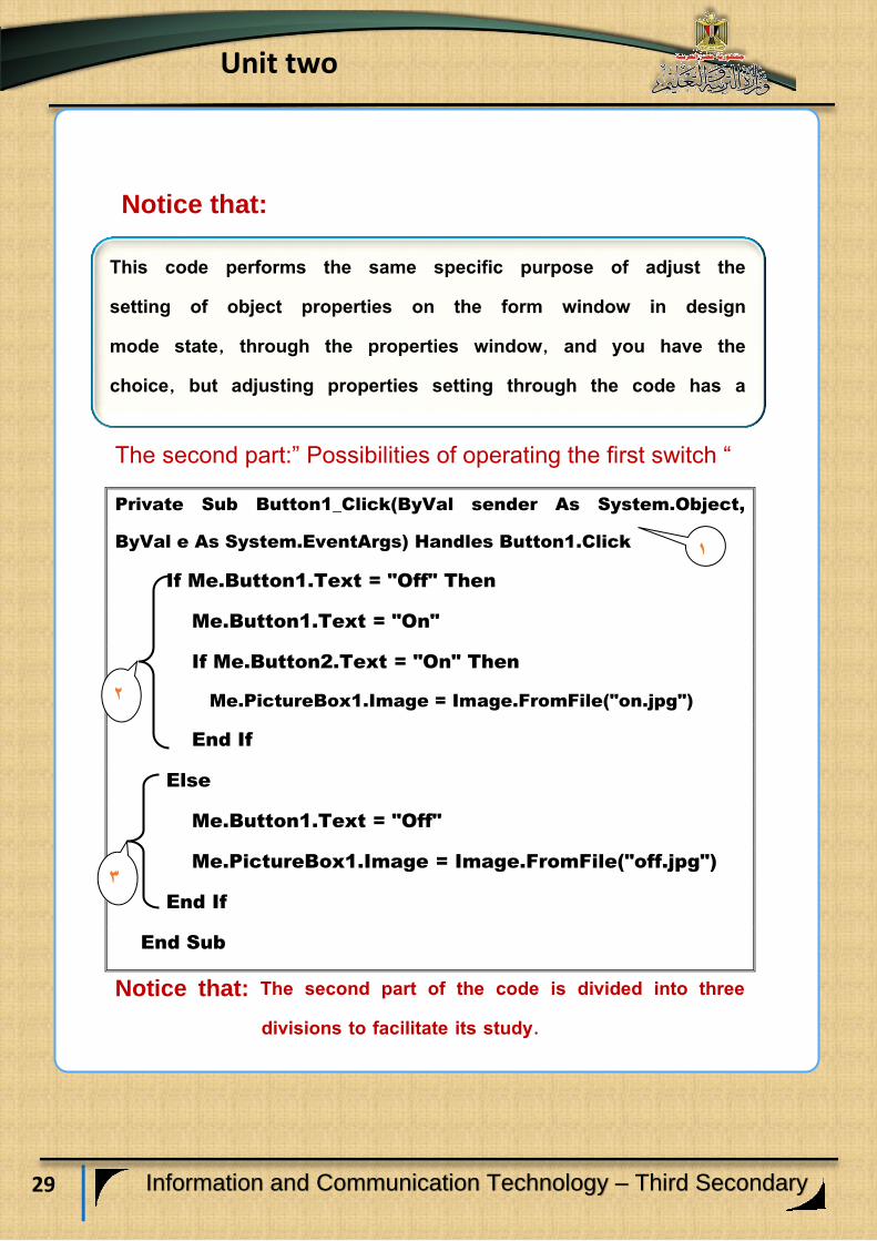
Notice that:
The second part:” Possibilities of operating the first switch “
Private Sub Button1_Click(ByVal sender As System.Object,
ByVal e As System.EventArgs) Handles Button1.Click
If Me.Button1.Text = "Off" Then
Me.Button1.Text = "On"
If Me.Button2.Text = "On" Then
Me.PictureBox1.Image = Image.FromFile("on.jpg")
End If
Else
Me.Button1.Text = "Off"
Me.PictureBox1.Image = Image.FromFile("off.jpg")
End If
End Sub
Notice that: The second part of the code is divided into three divisions to facilitate its study.
1
2
3
This code performs the same specific purpose of adjust the setting of object properties on the form window in design mode state, through the properties window, and you have the choice, but adjusting properties setting through the code has a better and stronger effect.
30
Unit two
Information and Communication Technology – Third Secondary
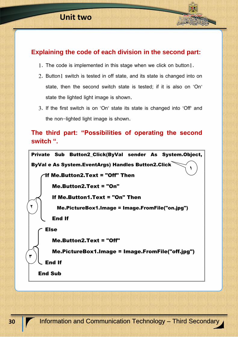
Explaining the code of each division in the second part:
1. The code is implemented in this stage when we click on button1. 2. Button1 switch is tested in off state, and its state is changed into on
state, then the second switch state is tested; if it is also on "On" state the lighted light image is shown.
3. If the first switch is on "On" state its state is changed into "Off" and the non-lighted light image is shown.
The third part: “Possibilities of operating the second
switch “.
Private Sub Button2_Click(ByVal sender As System.Object,
ByVal e As System.EventArgs) Handles Button2.Click
If Me.Button2.Text = "Off" Then
Me.Button2.Text = "On"
If Me.Button1.Text = "On" Then
Me.PictureBox1.Image = Image.FromFile("on.jpg")
End If
Else
Me.Button2.Text = "Off"
Me.PictureBox1.Image = Image.FromFile("off.jpg")
End If
End Sub
1
2
3

31
Unit two
Information and Communication Technology – Third Secondary
Explaining the code of each section in the third part:
(1) The code is implemented in this step when we click on Button 2. (2) Button 2 is tested in off state, we change its state into on, then we test
the first switch state if it is on the lighted light image is also shown. (3) If the second switch is in on state, its state is changed into off, and
the image of the non-lighted light is also shown.
Activity (2) Employing the code in production and
implementation of the project of the logic gate
"AND" simulation
STAGE (4)
Activity book (p: 11)
32
Unit two
Information and Communication Technology – Third Secondary
Learning outcomes: At the end of this subject, learner should have the ability to:
Explain stages of producing a project of the logic gate AND in PHP
language.
Produce a project of the work of the logic gate AND simulation
on the Internet browser screen in PHP language.
Explain the code that is used in the Implementation of the
project of the logic gate AND simulation.
Employ the PHP code in producing the project practically.
Producing a project of the logic AND
gate in PHP language

33
Unit two
Information and Communication Technology – Third Secondary
Requirements for the implementation of the project in PHP
language:
(1) Implementation of the project through the Internet browser
window based on some of the basics of markup language HTML,
Expression Web application, and PHP language that previously
studied.
(2) Using Expression Web application to set up a static Web page in
order to help you design the user's interface of the project and
display it on the browser screen.
Producing a project of the logic gate "AND" simulation in
PHP language is going through the following stages:
1-Designing stage:
Dear Student you can design your Web page from your proposal
contains the appropriate Controls to achieve the target of producing a
project of the logic gate "AND" simulation to display it on the Internet
browser screen.
2-The implementation stage of the web page project:
Dear student, there are many applications that can be used in
inserting controls on the browser window, like Expression Web
application, as you can put necessary texts, titles and Controls to
implement the design of the web page, through Control Tool Box.
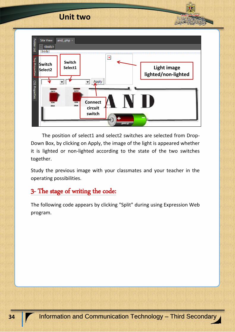
The following figure shows the proposals of a Web page design that
appears on the Internet browser window, and the implied Controls that
are necessary for producing the project.
34
Unit two
Information and Communication Technology – Third Secondary
The position of select1 and select2 switches are selected from Drop-
Down Box, by clicking on Apply, the image of the light is appeared whether
it is lighted or non-lighted according to the state of the two switches
together.
Study the previous image with your classmates and your teacher in the
operating possibilities.
3- The stage of writing the code:
The following code appears by clicking "Split" during using Expression Web
program.
Light image lighted/non-lighted
Connect circuit switch
SwitchSelect1
Switch Select2

35
Unit two
Information and Communication Technology – Third Secondary
<html>
<head>
<meta content="text/html; charset=utf-8" http-quiv="Content-Type" />
<title> AND GATE </title>
</head>
<body>
<form method="post"action=" ">
<?php
$lightstate="off.jpg";
$choosekey1="off";
$choosekey2="off";
if(isset($_POST['Submit1']))
{
$choosekey1=$_POST['Select1'];
$choosekey2=$_POST['Select2'];
if ($choosekey1=="on" && $choosekey2=="on" )
{ $lightstate="on.jpg"; }
else
{ $lightstate="off.jpg"; }
}
?>
<select name="Select1" style="width: 89px">
<option> on </option>
<option> off </option>
<option selected= 'selected'> <?php echo $choosekey1; ?> </option>
</select>
<select name="Select2" style="width: 94px" >
<option> on </option>
<option> off </option>
<option selected= 'selected'> <?php echo $choosekey2; ?>
</option>
</select>
<input name="Submit1" type="submit" value="Apply" />
<input name="Image1" type="image" height= "123" src="<?php echo $lightstate;
?>" width="105"/>
<br /> <img alt="" height="164" src="andconect1.jpg" width="604" />
</form>
</body>
</html>
1
2
3
4
36
Unit two
Information and Communication Technology – Third Secondary
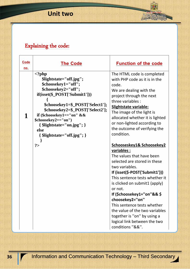
Explaining the code:
Function of the code The Code Code no.
The HTML code is completed with PHP code as it is in the code. We are dealing with the project through the next three variables : Slightstate variable: The image of the light is allocated whether it is lighted or non-lighted according to the outcome of verifying the condition. Schooseskey1& Schoosekey2 variables : The values that have been selected are stored in these two variables. If (isset($-POST{'Submit1'})) This sentence tests whether it is clicked on submit1 (apply) or not. If ($choosekey1=''on''&& $ choosekey2=''on'' This sentence tests whether the value of the two variables together is ''on'' by using a logical link between the two conditions ''&&''.
<?php
$lightstate="off.jpg";
$choosekey1="off";
$choosekey2="off";
if(isset($_POST['Submit1']))
{
$choosekey1=$_POST['Select1'];
$choosekey2=$_POST['Select2'];
if ($choosekey1=="on" &&
$choosekey2=="on")
{ $lightstate="on.jpg"; }
else
{ $lightstate="off.jpg"; } }
?>
1
37
Unit two
Information and Communication Technology – Third Secondary
Function of the code The Code Code No.
The code (Select): It is used to insert the first Drop-Down box, determine its name of property (name) and determine displaying Drop-Down width by the property Width. The code (Option): To determine the options to be displayed in the Drop-Down box. The code (php): <? Php echo $chooseswitch1 ;?> To print a selection value $chooseswitch1.
<select name="Select1" style="width:
89px">
<option> on </option>
<option> off </option>
<option selected= 'selected'>
<?php echo $choosekey1; ?>
</option>
</select>
2
The code (Select): It is used to insert the second Drop-Down box, determine its name of property (name) and determine displaying Drop-Down width by the property Width. The code (Option): To determine the options to be displayed in the Drop-Down box. The code (php): <? php echo $chooseswitch2 ;?> To print a selection value $choosekey2.
<select name="Select2" style="width:
94px" >
<option> on </option>
<option> off </option>
<option selected= 'selected'>
<?php echo $choosekey2; ?>
</option>
</select>
3

38
Unit two
Information and Communication Technology – Third Secondary
Function of the code The Code Code No.
-The code input: Its mission is to insert a button that has a name Submit1 by name property and determine the value Apply by Value.
<input name="Submit1"
type="submit" value="Apply" />
4 -The code input: To insert an object of image type, The source to get an image of the lighted light by the variable $lightstate, in php statement. -The code img: Inserting the image of the battery on the browser screen, and determining the image resource by the file andconect1.jpg.
<input name="Image1" type="image"
height= "123" src="<?php echo
$lightstate; ?>" width="105"/>
<img alt="" height="164"
src="andconect1.jpg" width="604" />

39
Unit two
Information and Communication Technology – Third Secondary
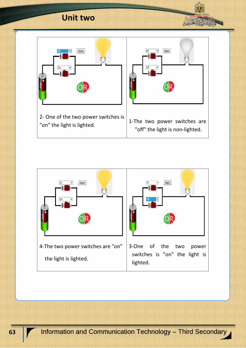
Possibilities of running the logic circuit AND on
the internet browser window.
2- One of the two power switches
are "off", the light is non-lighted
1- The two power switches are
"off", the light is non-lighted
4- The two power switches are
"on", the light is lighted
3- One of the two power switches
are "off", the light is non-lighted
Activity (1)
"Producing a project of logic AND gate simulation In PHP language
on the web page."
Activity book (p: 13)
40
Unit two
Information and Communication Technology – Third Secondary
Learning outcomes: At the end of this subject learner should have the ability to:
Explain the work of the logic gate OR.
Discuss the selecting gate code OR with his classmates.
Explain Truth Table of OR gate.
The Logic OR gate

41
Unit two
Information and Communication Technology – Third Secondary
Logic OR gate:
It is called selecting gate, it has two inputs or more, and only one
output, OR gate is represented electrically with two switches or more
which are conducted together in parallel (A, B) as each of the two switches
represents an input of the logic gate OR inputs, thus they represent (two
binary inputs), while the light (L) represents the output as it is shown in
the following equivalent figure of the selecting OR gate:
(The equivalent figure of the selecting OR gate)
Study the previous figure; describe it, conclude the relation between
its components, discuss this with your classmates and your teacher.
42
Unit two
Information and Communication Technology – Third Secondary
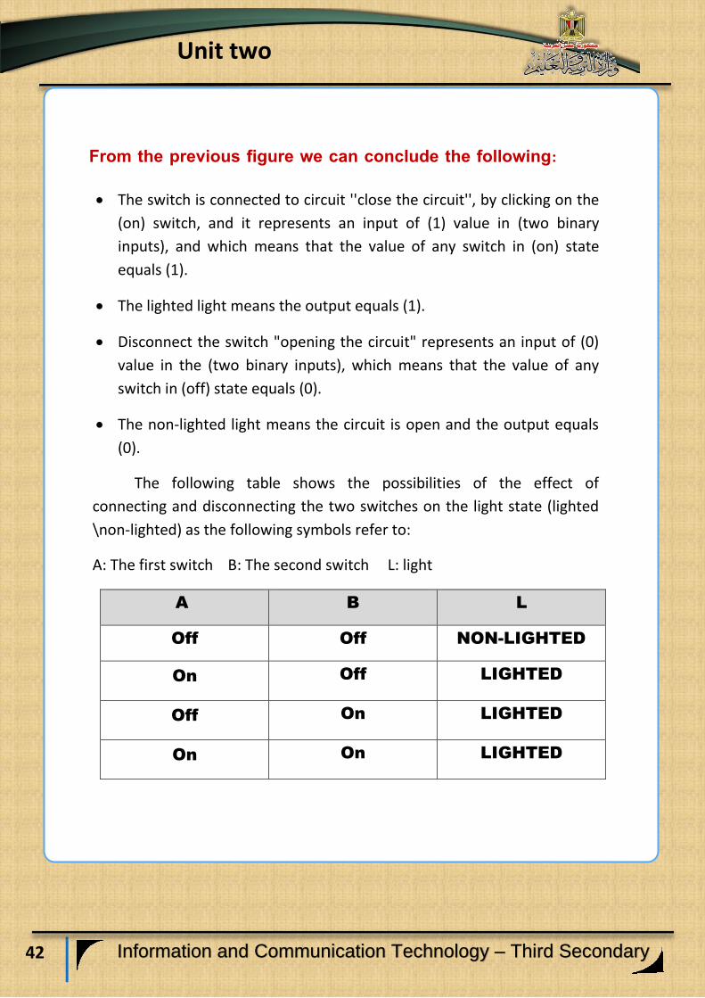
From the previous figure we can conclude the following:
The switch is connected to circuit ''close the circuit'', by clicking on the
(on) switch, and it represents an input of (1) value in (two binary
inputs), and which means that the value of any switch in (on) state
equals (1).
The lighted light means the output equals (1).
Disconnect the switch "opening the circuit" represents an input of (0)
value in the (two binary inputs), which means that the value of any
switch in (off) state equals (0).
The non-lighted light means the circuit is open and the output equals
(0).
The following table shows the possibilities of the effect of
connecting and disconnecting the two switches on the light state (lighted
\non-lighted) as the following symbols refer to:
A: The first switch B: The second switch L: light
L B A
NON-LIGHTED Off Off
LIGHTED Off On
LIGHTED On Off
LIGHTED On On
43
Unit two
Information and Communication Technology – Third Secondary
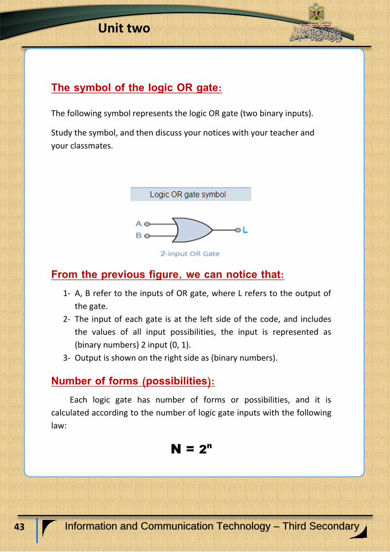
The symbol of the logic OR gate: The following symbol represents the logic OR gate (two binary inputs).
Study the symbol, and then discuss your notices with your teacher and
your classmates.
From the previous figure, we can notice that: 1- A, B refer to the inputs of OR gate, where L refers to the output of
the gate.
2- The input of each gate is at the left side of the code, and includes
the values of all input possibilities, the input is represented as
(binary numbers) 2 input (0, 1).
3- Output is shown on the right side as (binary numbers).
Number of forms (possibilities): Each logic gate has number of forms or possibilities, and it is
calculated according to the number of logic gate inputs with the following
law:
N = 2n
44
Unit two
Information and Communication Technology – Third Secondary
As N refers to the number of forms, as this law is previously studied in the
first subject the Logic AND gate.
Example: OR gate (two binary inputs), its forms are calculated as:
N= 22
=4
But if the OR gate that has three inputs, its forms or possibilities are:
N=23
=8
By the same method, you can calculate the forms or possibilities of any OR
gate.
Truth Table: Truth table helps in explaining the logic OR gate behaviors according to the
relation between inputs and output of the logic gate.
If the value of the two inputs (A, B) equals (0), output will not be found
which means:
(L) = (0)
Which means: if the two conditions don't exist together, we can't get the
output, which is represented on the electric figure that simulates the
selecting OR gate.
The light is lighted when any condition of them or both of them exist
together, and the value is (On).
45
Unit two
Information and Communication Technology – Third Secondary
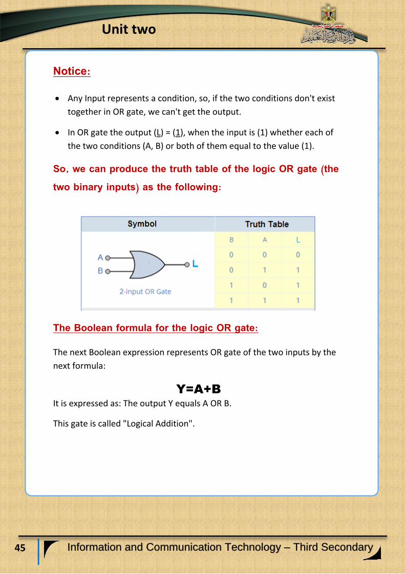
Notice:
Any Input represents a condition, so, if the two conditions don't exist
together in OR gate, we can't get the output.
In OR gate the output (L) = (1), when the input is (1) whether each of
the two conditions (A, B) or both of them equal to the value (1).
So, we can produce the truth table of the logic OR gate (the two binary inputs) as the following:
The Boolean formula for the logic OR gate:
The next Boolean expression represents OR gate of the two inputs by the
next formula:
Y=A+B
It is expressed as: The output Y equals A OR B.
This gate is called "Logical Addition".
46
Unit two
Information and Communication Technology – Third Secondary
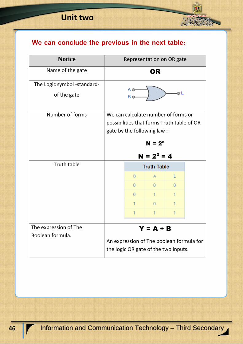
We can conclude the previous in the next table:
Representation on OR gate Notice
OR Name of the gate
The Logic symbol -standard-
of the gate
We can calculate number of forms or
possibilities that forms Truth table of OR
gate by the following law :
N = 2n
N = 22
= 4
Number of forms
Truth table
Y = A + B
An expression of The boolean formula for
the logic OR gate of the two inputs.
The expression of The
Boolean formula.
47
Unit two
Information and Communication Technology – Third Secondary
Activity (1)
"Truth table of the logic OR gate"
Activity book (p: 15)

48
Unit two
Information and Communication Technology – Third Secondary
Learning outcomes:
At the end of this subject learner should have the ability to:
Explain stages of producing a project of the logic gate (OR)
simulation by using (VB.NET) language.
Design the interface of the project by using Visual Studio.NET
application.
Explain the code that is used in a project of operating the logic
gate OR simulation.
Employ the code in the project implementation practically.
Producing a project of the
logic OR gate simulation
49
Unit two
Information and Communication Technology – Third Secondary
The project purpose:
Producing a program that simulates the logic OR gate.
Requirements of producing the project:
1- Providing the scientific background of the logic gate OR in terms of:
Its concept, its truth table, and the Boolean formula of the logic
gate, and that is what is studied before.
2- Selecting the programming language that you can use in producing
the project and you can benefit from your previous experience in
Visual Basic.NET language or PHP language.
Stages of the project implementation:
1- Designing the user's interface of the project “Graphic User
Interface" GUI, and determining appropriate Controls for each use
to produce the project properly.
2- Adjusting the controls properties in the light of the necessary needs
for the production of the project.
3- Writing the programming code.
Stages of the project production:
Firstly: Designing the user's interface of the project:
You can design the user's interface of the project and put appropriate
controls on it to achieve the purpose of (connecting- disconnecting)
electric light switch simulation.
50
Unit two
Information and Communication Technology – Third Secondary
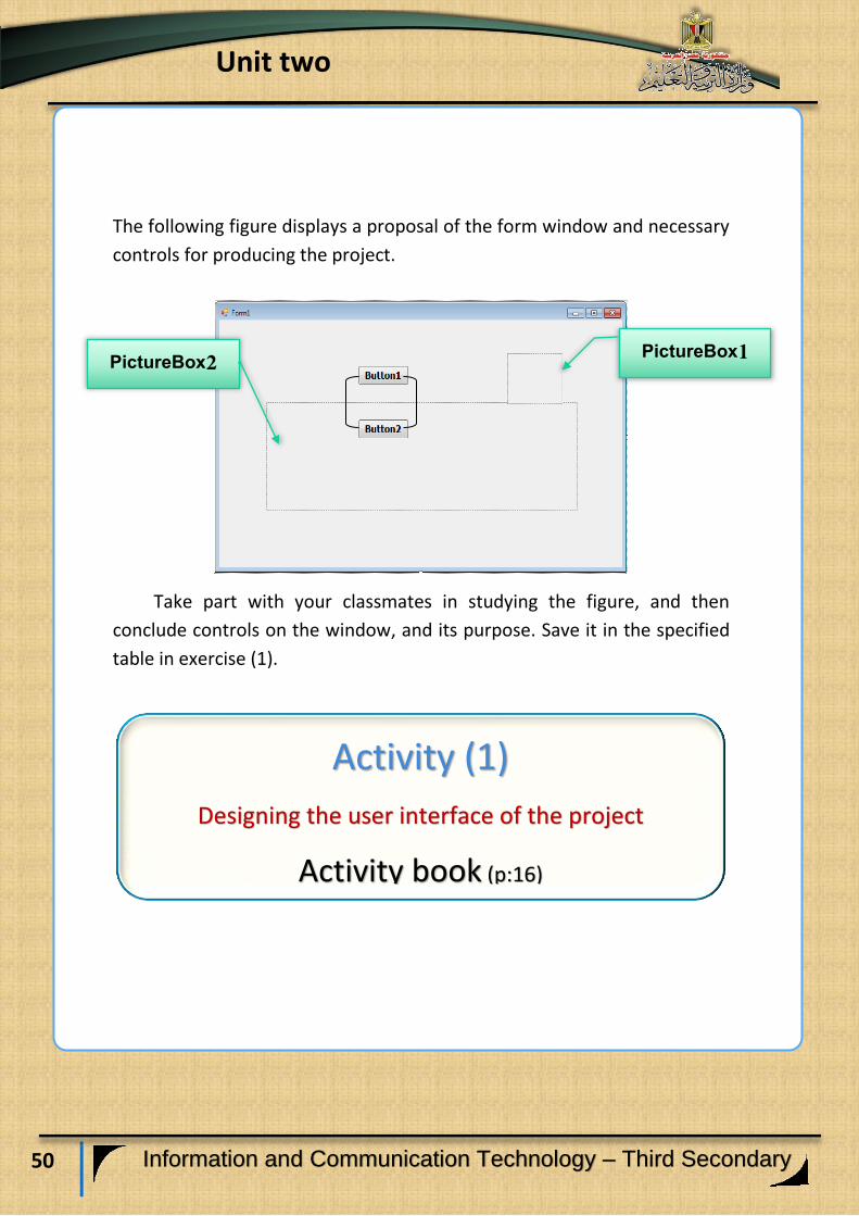
The following figure displays a proposal of the form window and necessary
controls for producing the project.
Take part with your classmates in studying the figure, and then
conclude controls on the window, and its purpose. Save it in the specified
table in exercise (1).
Activity (1)
Designing the user interface of the project
Activity book (p:16)
PictureBox1 PictureBox2
51
Unit two
Information and Communication Technology – Third Secondary
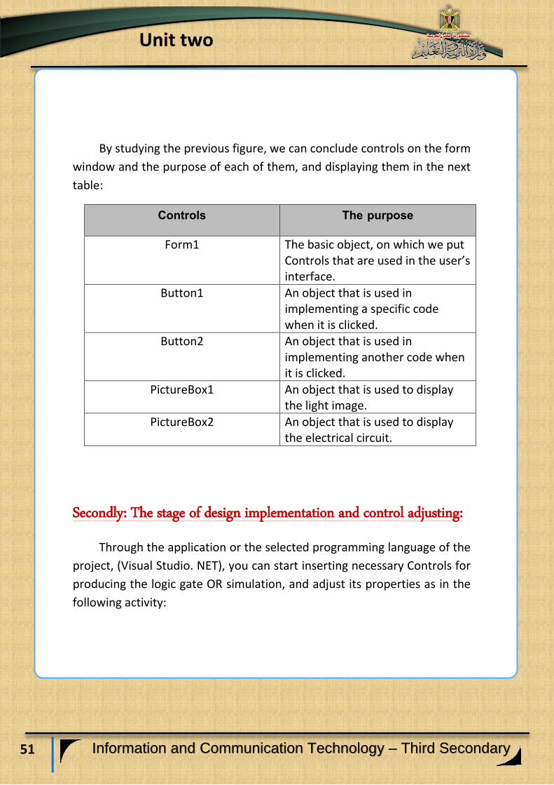
By studying the previous figure, we can conclude controls on the form
window and the purpose of each of them, and displaying them in the next
table:
Controls The purpose
Form1 The basic object, on which we put Controls that are used in the user’s interface.
Button1 An object that is used in implementing a specific code when it is clicked.
Button2 An object that is used in implementing another code when it is clicked.
PictureBox1 An object that is used to display the light image.
PictureBox2 An object that is used to display the electrical circuit.
Secondly: The stage of design implementation and control adjusting:
Through the application or the selected programming language of the
project, (Visual Studio. NET), you can start inserting necessary Controls for
producing the logic gate OR simulation, and adjust its properties as in the
following activity:

52
Unit two
Information and Communication Technology – Third Secondary
Thirdly: The stage of writing the programming code:
Before starting to write and implement the project code, try to
guess the possible results of flowing or not flowing of the current in the
circuit, there are four possibilities that we can display in the following
table:
First switch state: off
Second switch state: off
Light image: non-lighted
First switch state: on
Second switch state: on
Light image: lighted
Activity (2)
Implementing a design of the user interface
application (Visual Studio.Net)
Activity book (p:17)

53
Unit two
Information and Communication Technology – Third Secondary
First switch state: off
Second switch state: on
Light image: lighted
First switch state: on
Second switch state: off
Light image: lighted
From the previous table, we can conclude the following:
Switch state is changed between "On "and" Off" by clicking (Click)
on the switch.
There are two images of the light in two separated files, (one of
them is lighted and the other is non-lighted), which are shown on
PictureBox1.
The idea of the code is summarized in the following:
1. Selecting an object or more that is responsible for the code
implementation, on the occurrence of a particular event.
In this project, we can write the code in the following objects:
Form object in loading event form1_load:
To show the non-lighted light image, the" circuit" image, and showing
the state of the two switches "off".
54
Unit two
Information and Communication Technology – Third Secondary
Button1 object:
When we press click, switch state is selected, and its state is changed
between (Off, On).
Testing first and second switches state and changing the light image into
the valid state that is appropriate to the two switches state.
Button2 object:
When we press click, switch state is tested, and its state is changed
between (Off, On).
Testing first and second switches state and changing the light image into
the valid state that is appropriate to the two switches state.
2. Writing the code of each object from the three previous objects.
In producing a project of logic OR gate simulation, we will study and
explain the used code through a particular code of the book , its operating
effect is represented on Light state ,whether it is lighted or non-lighted
according to the two switches state,
Whether it is "On "or "Off "after pressing Click on the two switches,
through the following code:
55
Unit two
Information and Communication Technology – Third Secondary
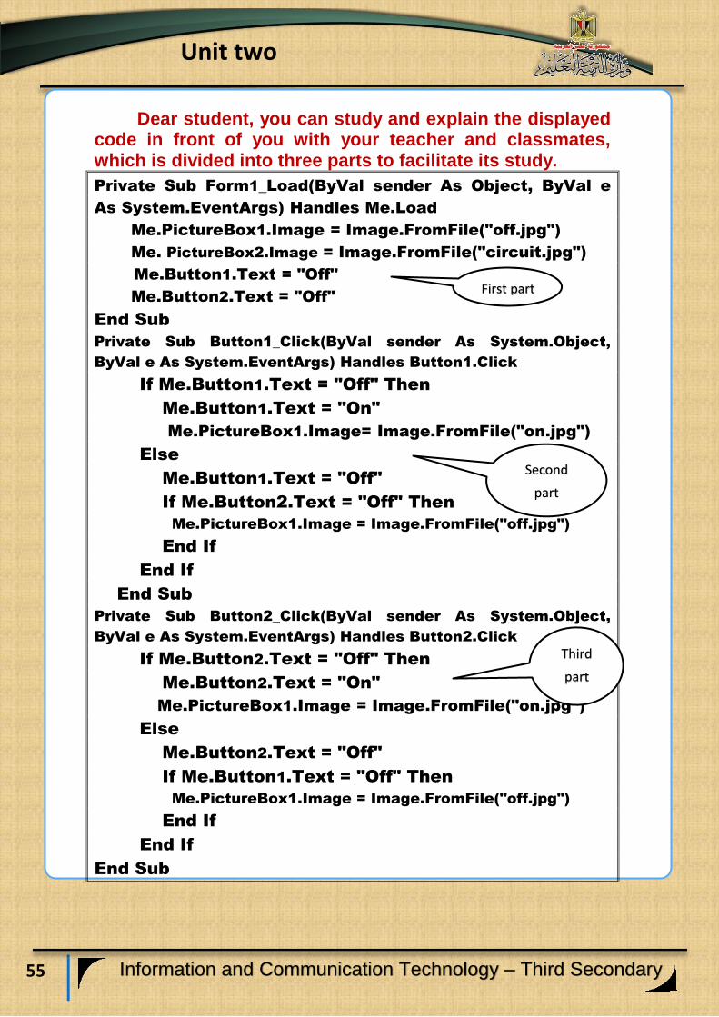
Dear student, you can study and explain the displayed code in front of you with your teacher and classmates, which is divided into three parts to facilitate its study.
Private Sub Form1_Load(ByVal sender As Object, ByVal e
As System.EventArgs) Handles Me.Load
Me.PictureBox1.Image = Image.FromFile("off.jpg")
Me. PictureBox2.Image = Image.FromFile("circuit.jpg")
Me.Button1.Text = "Off"
Me.Button2.Text = "Off"
End Sub
Private Sub Button1_Click(ByVal sender As System.Object,
ByVal e As System.EventArgs) Handles Button1.Click
If Me.Button1.Text = "Off" Then
Me.Button1.Text = "On"
Me.PictureBox1.Image= Image.FromFile("on.jpg")
Else
Me.Button1.Text = "Off"
If Me.Button2.Text = "Off" Then
Me.PictureBox1.Image = Image.FromFile("off.jpg")
End If
End If
End Sub
Private Sub Button2_Click(ByVal sender As System.Object,
ByVal e As System.EventArgs) Handles Button2.Click
If Me.Button2.Text = "Off" Then
Me.Button2.Text = "On"
Me.PictureBox1.Image = Image.FromFile("on.jpg")
Else
Me.Button2.Text = "Off"
If Me.Button1.Text = "Off" Then
Me.PictureBox1.Image = Image.FromFile("off.jpg")
End If
End If
End Sub
First part
Second
part
Third
part
56
Unit two
Information and Communication Technology – Third Secondary
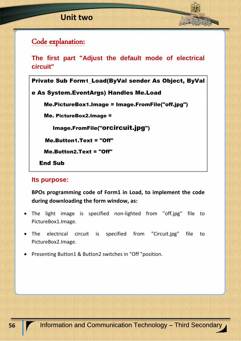
Code explanation:
The first part "Adjust the default mode of electrical
circuit"
Private Sub Form1_Load(ByVal sender As Object, ByVal
e As System.EventArgs) Handles Me.Load
Me.PictureBox1.Image = Image.FromFile("off.jpg")
Me. PictureBox2.Image =
Image.FromFile("orcircuit.jpg")
Me.Button1.Text = "Off"
Me.Button2.Text = "Off"
End Sub
Its purpose:
BPOs programming code of Form1 in Load, to implement the code
during downloading the form window, as:
The light image is specified non-lighted from ''off.jpg'' file to
PictureBox1.Image.
The electrical circuit is specified from "Circuit.jpg" file to
PictureBox2.Image.
Presenting Button1 & Button2 switches in "Off "position.
57
Unit two
Information and Communication Technology – Third Secondary
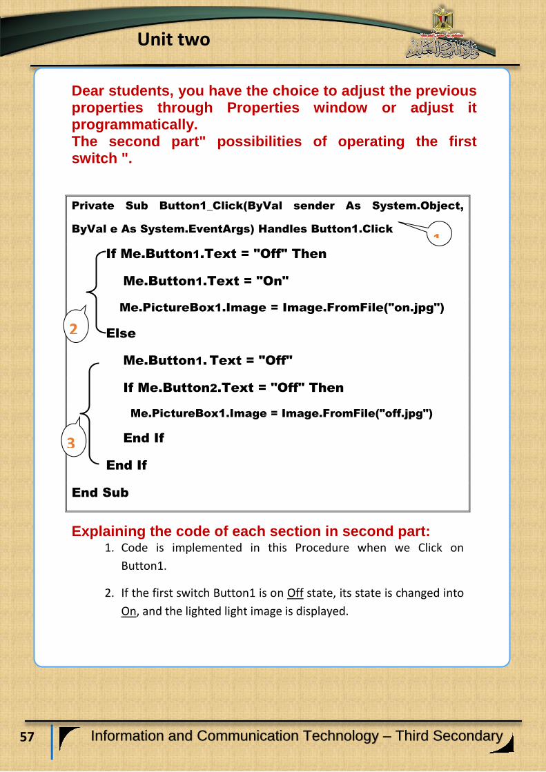
Dear students, you have the choice to adjust the previous properties through Properties window or adjust it programmatically. The second part" possibilities of operating the first switch ".
Private Sub Button1_Click(ByVal sender As System.Object,
ByVal e As System.EventArgs) Handles Button1.Click
If Me.Button1.Text = "Off" Then
Me.Button1.Text = "On"
Me.PictureBox1.Image = Image.FromFile("on.jpg")
Else
Me.Button1. Text = "Off"
If Me.Button2.Text = "Off" Then
Me.PictureBox1.Image = Image.FromFile("off.jpg")
End If
End If
End Sub
Explaining the code of each section in second part: 1. Code is implemented in this Procedure when we Click on
Button1.
2. If the first switch Button1 is on Off state, its state is changed into
On, and the lighted light image is displayed.
1
2
3

58
Unit two
Information and Communication Technology – Third Secondary
3. But, if the first switch Button1 is on On state, its state is changed
into Off, and testing the second switch state , if it is on Off state,
this means that the two switches states are on Off state ,and the
non-lighted light image is displayed.
The third part: "possibilities of operating the second switch".
Private Sub Button2_Click(ByVal sender As System.Object,
ByVal e As System.EventArgs) Handles Button2.Click
If Me.Button2.Text = "Off" Then
Me.Button2.Text = "On"
Me.PictureBox1.Image = Image.FromFile("on.jpg")
Else
Me.Button2.Text = "Off"
If Me.Button1.Text = "Off" Then
Me.PictureBox1.Image = Image.FromFile("off.jpg")
End If
End If
End Sub
Explaining the code of each section in third part:
1. Code is implemented in this action when we Click on Button2.
2. If the second switch Button2 is on Off state, its state is changed
into On, and the lighted light image is displayed.
3. If the second switch Button2 is on On state, its state is changed
into Off, and then testing the first switch state , if it is on Off
state, this means that the two switches states are on Off state
,and the non-lighted light image is shown.
1
2
3
59
Unit two
Information and Communication Technology – Third Secondary
Activity (3) You can use the code in producing and implementing
"The logic OR gate simulation project"
Procedure No (4)
Activity book (p:20)

60
Unit two
Information and Communication Technology – Third Secondary
Learning outcomes:
At the end of this subject, learner should have the ability to:
- Explain stages of producing a project of logic gate OR in PHP
language.
- Produce a project of the logic gate OR work simulation on
the Internet browser screen in PHP language.
- Explain PHP code in implementing a project of logic gate OR
simulation.
- Employ PHP code in producing a project.
Producing a project of logic OR gate in PHP
language

61
Unit two
Information and Communication Technology – Third Secondary
Requirements of the project implementation in PHP language:
(1) Project implementation through Internet browser window depends on some basics of markup language HTML, Expression Web application and PHP language that is studied before.
(2) Using Expression Web application to create a Static Web Page, to help you in designing the user's interface of the project, and displaying it on the browser window.
Producing a project of logic OR gate simulation in PHP
language passes through the following stages:
1- Designing stage:
Dear student, you can design a web page from your own, which
contains the possible controls of achieving the purpose, which is producing
the project "logic OR gate simulation" and displaying it on the browser
window.
2- Stage of implementing the web page of the project:
Dear student, there are a lot of applications that you can use in adding
controls on the browser window, as Expression Web, and through Toolbox,
you can put necessary articles, titles and controls to implement designing
the web page.
62
Unit two
Information and Communication Technology – Third Secondary
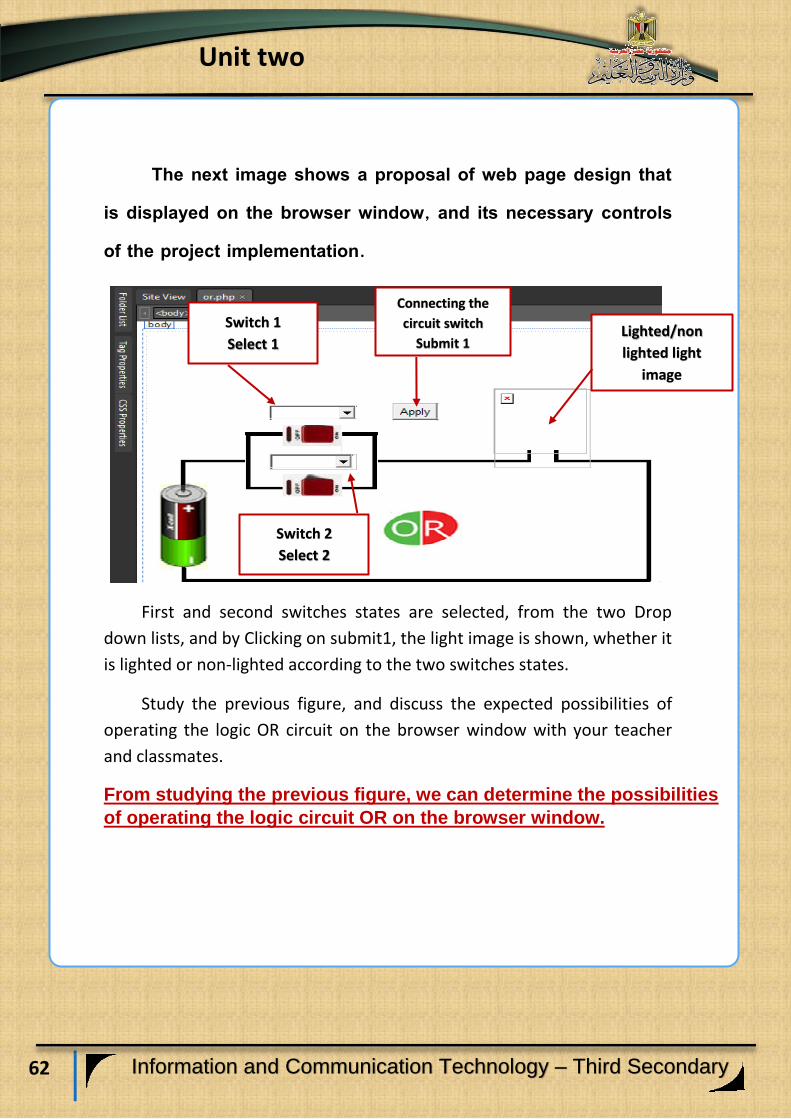
The next image shows a proposal of web page design that is displayed on the browser window, and its necessary controls of the project implementation.
First and second switches states are selected, from the two Drop
down lists, and by Clicking on submit1, the light image is shown, whether it
is lighted or non-lighted according to the two switches states.
Study the previous figure, and discuss the expected possibilities of
operating the logic OR circuit on the browser window with your teacher
and classmates.
From studying the previous figure, we can determine the possibilities
of operating the logic circuit OR on the browser window.
Lighted/non
lighted light
image
Connecting the
circuit switch
Submit 1
Switch 1
Select 1
Switch 2
Select 2
63
Unit two
Information and Communication Technology – Third Secondary
1-The two power switches are
"off" the light is non-lighted.
2- One of the two power switches is
"on" the light is lighted.
3-One of the two power
switches is "on" the light is
lighted.
4-The two power switches are "on"
the light is lighted.

64
Unit two
Information and Communication Technology – Third Secondary
3- Stage of writing the programming code:
Dear students, you can employ the programming code in PHP
language, in treating data of the web page and put the Controls objects on
the model window of the interface application of the project. Thus
through your implementation of the following activity in the activities
book, as the previous study of explaining the code of the logic gate AND,
under the supervision of your teacher.
Activity (1)
Employing PHP code in producing a project that
simulates the logic OR gate
Activity book (22)
65
Unit two
Information and Communication Technology – Third Secondary
Learning outcomes:
At the end of this subject, learners should have the ability to:
Explain the logic NOT gate. Discuss the code of the logic NOT gate with his
classmates. Conclude Truth Table of NOT gate.
The logic NOT gate

66
Unit two
Information and Communication Technology – Third Secondary
The logic gate NOT:
It is called the Inverter Gate, it is the gate that has only one input
and one output, and the inverter changes the logic value of the input into
its reflection, so if the value of the input is (1), the value of the output is (0)
and if the value of the input is (0) the value of the output is (1).
The NOT gate is represented electrically with only one switch (A) as
the gate input, and the light (L) represents the gate output, as what is
shown in the following simulating figure of the Inverter Gate NOT:
The simulating figure of the Inverter NOT gate
Study the previous figure of the selecting NOT gate simulation,
describe it, conclude the relationship among its components, and discuss
the results with your classmates and teachers.
From the previous simulating figure of the Inverter NOT Gate,
we can conclude the possibilities of the effect of opening or shutting
the switch on Light state, and representing it on the following table:

67
Unit two
Information and Communication Technology – Third Secondary
Assume A: switch state L: light.
Table shows the effect of opening or shutting the switch on the Light:
A L
OFF Lighted
ON Non-lighted
- From the previous table, we can conclude that the light is lighted only
when the switch is separated and be in Off state.
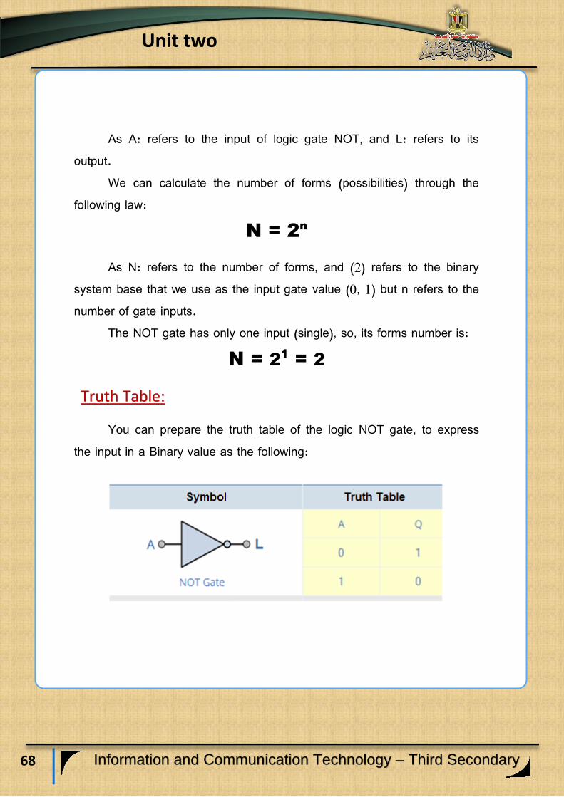
The symbol of NOT gate:
The logic gate symbol of NOT gate is presented as:
The logic gate symbol of NOT gate
68
Unit two
Information and Communication Technology – Third Secondary
As A: refers to the input of logic gate NOT, and L: refers to its output.
We can calculate the number of forms (possibilities) through the following law:
N = 2n
As N: refers to the number of forms, and (2) refers to the binary system base that we use as the input gate value (0, 1) but n refers to the number of gate inputs.
The NOT gate has only one input (single), so, its forms number is: N = 2
1
= 2
Truth Table:
You can prepare the truth table of the logic NOT gate, to express the input in a Binary value as the following:

69
Unit two
Information and Communication Technology – Third Secondary
Discuss the previous table with your teacher and classmates.
From the previous table, it is clear that:
Any input represents one condition, so, if the condition exists in the
logic NOT gate, the result will be the absence of the output.
In NOT gate the output = (1) when the input = (0).
The Boolean formula of the Logic gate NOT:
The Boolean expression that represents NOT gate is expressed by the
following formula.
Y = A
It is said:
The output Y equals NOT A
We can summarize the above in the following table:
Representation at the NOT gate Statement
NOT Gate name
Logic symbol standard of
the gate
Number of forms or possibilities of the
truth table is calculated by the following
law
N = 2n
N = 21
= 2
Number of forms
70
Unit two
Information and Communication Technology – Third Secondary
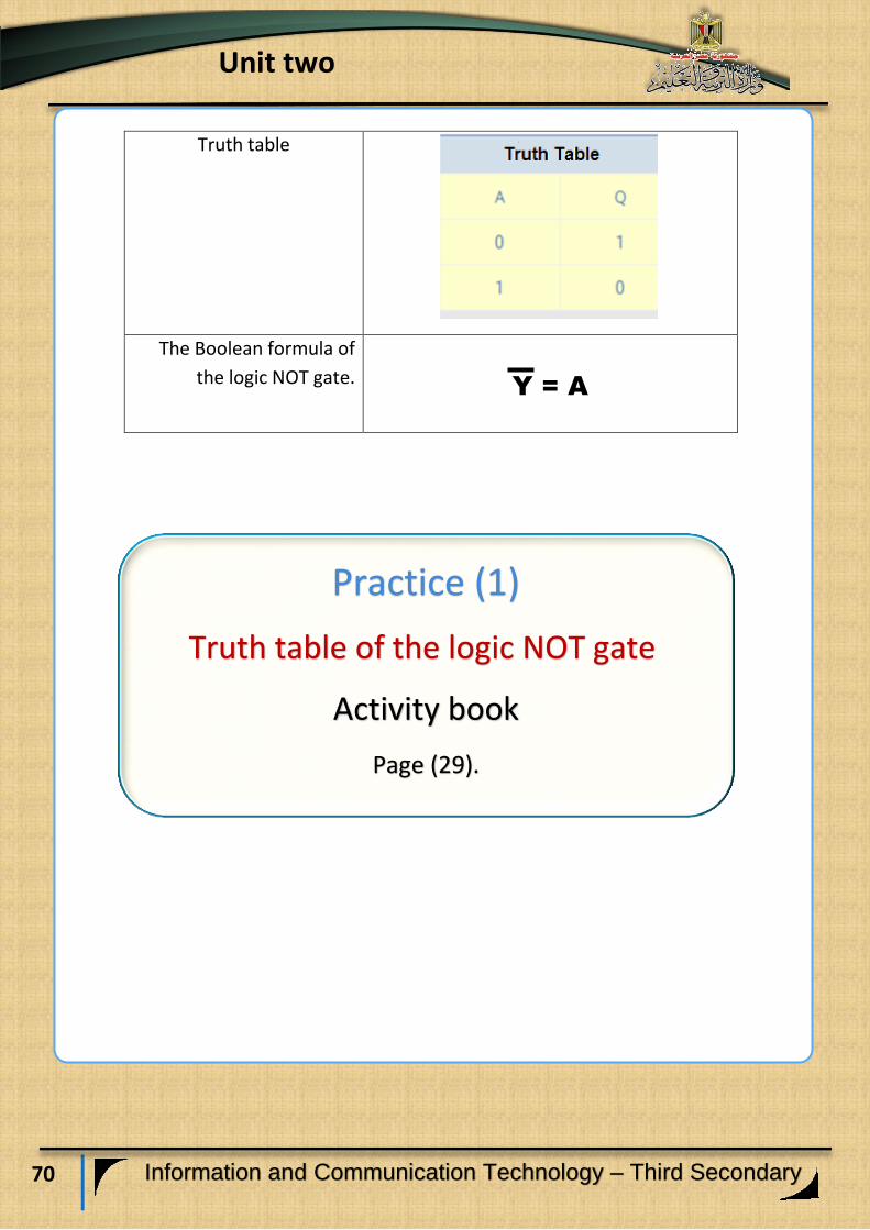
Truth table
Y = A
The Boolean formula of
the logic NOT gate.
Practice (1)
Truth table of the logic NOT gate
Activity book
Page (29).
71
Unit two
Information and Communication Technology – Third Secondary
Learning outcomes:
At the end of this subject, learner should have the ability to:
Recognize the stages of a project of logic NOT gates simulation by using VB.NET language.
Implement the user's interface design of a project of logic gates NOT simulation by using Visual Studio .NET application and one of the graphic programs.
Explain the code that is used in a project of operating the logic NOT gate simulation.
Employ the code that is used in the project implementation practically.
A project of the logic NOT
gate simulation.

72
Unit two
Information and Communication Technology – Third Secondary
The project purpose: Producing a program that simulates the logic NOT gate.
Requirements of producing the project: 1- 1-Providing the scientific background of the logic gate NOT In terms
of its concept, its truth table, and the Boolean formula of the gate,
and that what is previously studied.
2- 2-Providing the experience in coding languages that you can use in
producing the project and you can benefit from your previous
experience in Visual Basic.NET language.
Stages of the project implementation: 1- Designing the user's interface of the project “Graphic User
Interface" GUI, and determining appropriate Controls for each use
to produce the project properly.
2- Setting the Controls properties in the light of the necessary needs
for producing the project.
3- Writing the programming code.

73
Unit two
Information and Communication Technology – Third Secondary
Stages of the project production Firstly: designing stage:
The following figure is the proposed model window and its necessary
Controls of producing the project:
(Employ one of the graphic programs in designing the circuit image
and the lighted and non-lighted light images).
Practice (1)
Designing the user interface by using
(Visual Studio.NET)
Activity book Page (30)

74
Unit two
Information and Communication Technology – Third Secondary
Secondly: Implementation stage: Use the selected application or coding language in starting inserting
necessary Controls to implement the form design of the project of the
logic NOT gate simulation.
Practice (2)
Designing the user interface of the project
Activity book Page (28:31)

75
Unit two
Information and Communication Technology – Third Secondary
Thirdly: stage of writing programming code: Before starting writing the project code, try to predict the possible
results of the relation between the input and the output that help you in
the project code implementation, which is about the following
possibilities:
- Switch state: On
- Light image: non-lighted
- Switch state: Off
- Light image: lighted
The idea of the code is summarized in the following: (1) Determining the object (or more) that is responsible for the code
implementation upon the occurrence of a particular event on it, in this
project ,we can write the code in the following objects:
- Object model in Form_Load.
To show the non-lighted light and the circuit images and showing the
switch state '' 0n''.
- Button1:
To select switch state, which is On or Off and its effect on changing the
light image into the valid appropriate state to the operating switch state in
view of the truth table of the logic NOT gate.
76
Unit two
Information and Communication Technology – Third Secondary
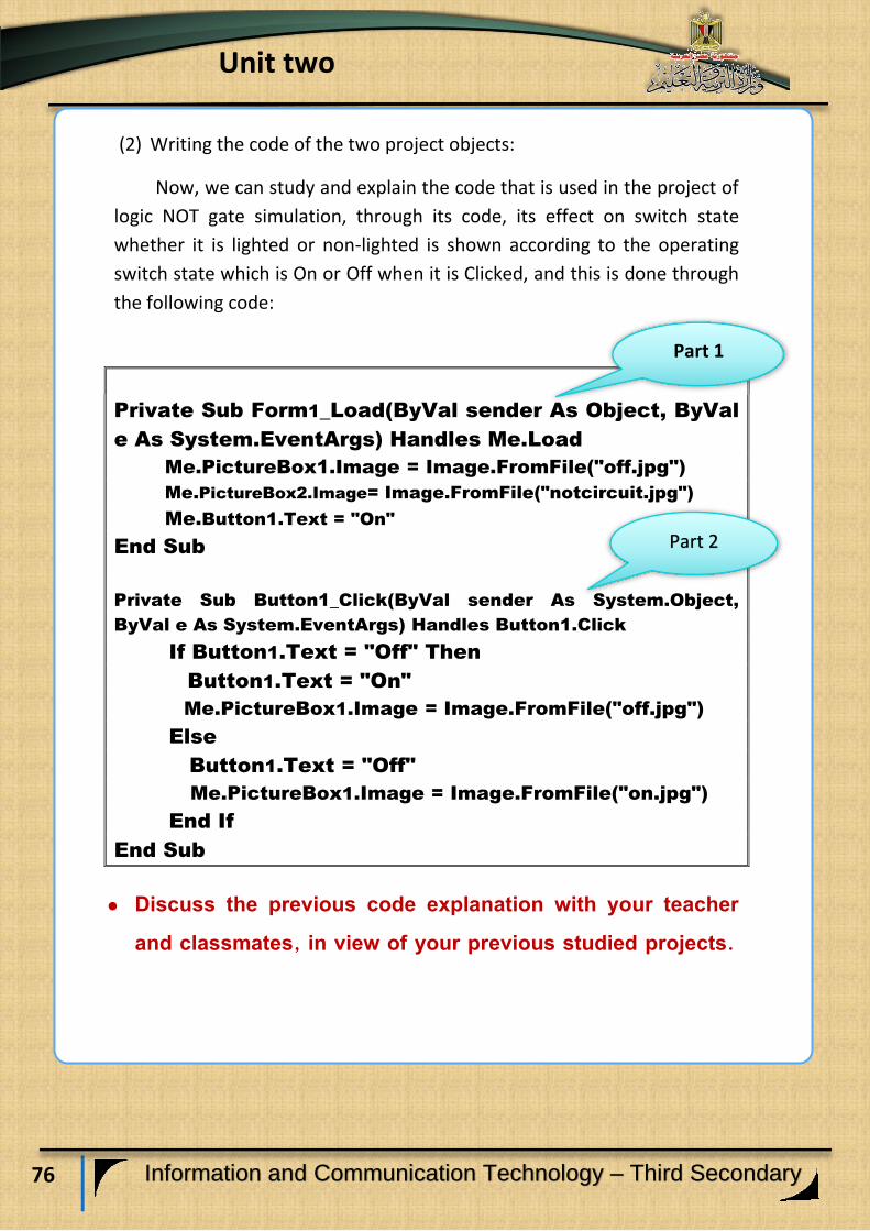
(2) Writing the code of the two project objects:
Now, we can study and explain the code that is used in the project of
logic NOT gate simulation, through its code, its effect on switch state
whether it is lighted or non-lighted is shown according to the operating
switch state which is On or Off when it is Clicked, and this is done through
the following code:
Private Sub Form1_Load(ByVal sender As Object, ByVal
e As System.EventArgs) Handles Me.Load
Me.PictureBox1.Image = Image.FromFile("off.jpg")
Me.PictureBox2.Image= Image.FromFile("notcircuit.jpg")
Me.Button1.Text = "On"
End Sub
Private Sub Button1_Click(ByVal sender As System.Object,
ByVal e As System.EventArgs) Handles Button1.Click
If Button1.Text = "Off" Then
Button1.Text = "On"
Me.PictureBox1.Image = Image.FromFile("off.jpg")
Else
Button1.Text = "Off"
Me.PictureBox1.Image = Image.FromFile("on.jpg")
End If
End Sub
Discuss the previous code explanation with your teacher and classmates, in view of your previous studied projects.
Part 1
Part 2

77
Unit two
Information and Communication Technology – Third Secondary
Practices (3),(4)
"Study of the code that is used in production and
implementation of the project simulation of operating the
logic NOT gate"
Activity book Page (33:35)

78
Unit two
Information and Communication Technology – Third Secondary
Learning outcomes:
At the end of this subject learner should have the ability to:
Conclude stages of logic gate NOT simulation project in PHP
language.
Implement the user's interface design of logic gate NOT
simulation project by using Expression Web application.
Explain the code that is used in logic gate NOT simulation project.
Employ PHP code practically in producing the project.
Producing a project of the logic NOT gate in PHP language

79
Unit two
Information and Communication Technology – Third Secondary
Requirements of the project implementation in PHP language:
(1) Implementing the project through the Internet browser screen depends
on some basics of HTML coding language, Expression Web application
and PHP language.
(2) Using Expression Web application to create a Static Web Page in order
to help you in designing the user's interface of the project and
displaying it on the browser screen.
Producing a project of the logic NOT gate simulation
(by using PHP language) passes through the following
stages:
1- Designing stage:
Dear student, you can design a web page that has the appropriate
controls to achieve the purpose of producing a project of the logic NOT
gate simulation, in order to display it on the Internet browser window.
2- The stage of implementing the web page of the project:
Dear student, there are a lot of applications that you can use to add
Controls on the browser window, as Expression Web application , as you
can add necessary text, titles and controls to implement a design of the
web page through Control ToolBox.
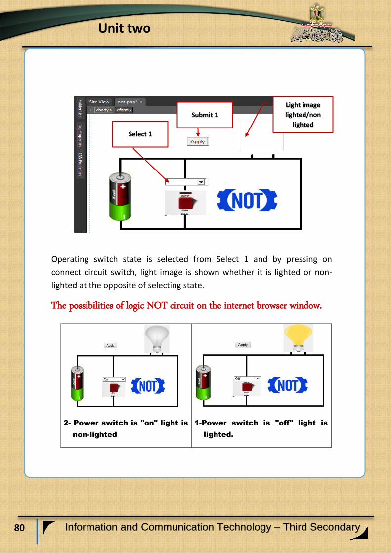
The following figure show a proposal of a web page design
which is displayed on internet browser screen, and its
necessary Controls of producing the project.
80
Unit two
Information and Communication Technology – Third Secondary
Operating switch state is selected from Select 1 and by pressing on
connect circuit switch, light image is shown whether it is lighted or non-
lighted at the opposite of selecting state.
The possibilities of logic NOT circuit on the internet browser window.
1-Power switch is "off" light is
lighted.
2- Power switch is "on" light is
non-lighted
Light image
lighted/non
lighted
Submit 1
Select 1
81
Unit two
Information and Communication Technology – Third Secondary
You can practice the following activity from Activities and exercises
book, in view of the projects of the logic circuits which are previously
studied , and thus through your co-operation with your classmates and
your teacher.
(1)
Activity (1)
"Employing PHP code in producing a project of the
logic NOT gate simulation on the web page"
Activity book Page (37).
82
Unit two
Information and Communication Technology – Third Secondary
Learning outcomes:
At the end of this subject learner should have the ability to:
Examine the problem depending on the possible inputs
and required outputs.
Make use of logical thinking in the problem solution.
Select the appropriate logic gate to solve the problem.
Employ the logic gates in life – taking decisions.
Employing logic gates in life–taking decisions
83
Unit two
Information and Communication Technology – Third Secondary
Do you know, dear students that the behavior you can precede in life-
taking decisions, is enormously similar to the logic gate idea:
As, taking any decision depends on the possible inputs and required
outputs, and selections depend on the logic gate type that is appropriate
to decision kind that is taken.
We hope to ensure on the importance of the logic gates and clarify it
as a method of thinking and a life style that we can practice and use
unconsciously in taking any decision , especially when this decision
depends on more than one condition or one input.
Example:
We have an example that shows employing the logic gate in taking
decision:
The ministry of Housing and constructing societies declares about
the beginning of booking in youth society project, and to be accepted, you
have to be older than 25 years old and to be married.
By examining the declaration of the competition we reached that:
The required output is accepting the applicant form of housing.
Number of conditions (outputs) is two conditions:
- Age is to be older than 25.
- The applicant marital status is to be married.
The two conditions have to be existed together in order to reach
the application to acceptance stage.
84
Unit two
Information and Communication Technology – Third Secondary
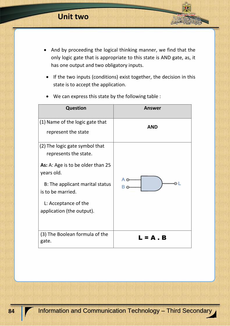
And by proceeding the logical thinking manner, we find that the
only logic gate that is appropriate to this state is AND gate, as, it
has one output and two obligatory inputs.
If the two inputs (conditions) exist together, the decision in this
state is to accept the application.
We can express this state by the following table :
Answer Question
AND (1) Name of the logic gate that
represent the state
(2) The logic gate symbol that
represents the state.
As: A: Age is to be older than 25
years old.
B: The applicant marital status
is to be married.
L: Acceptance of the
application (the output).
L = A . B (3) The Boolean formula of the gate.

85
Unit two
Information and Communication Technology – Third Secondary
(4) Truth table of the logic gate
that represents the state.
As we find that the only state
that produces the output is the
existence of the two conditions
A, B together, which makes the
application accepted.
As the previous, you can study the applications of the following activity
with your classmates and with your teacher's help.
(2)
Activity (1)
Applications on "employing
Logic gates in life taking-decisions"
Activity book Page (41)
86
Unit two
Information and Communication Technology – Third Secondary
Book conclusion
Dear students:
By the end of the second unit, third grade book of INFORMATION& COMMUNICATION TECHNOLOGY is finished through producing the suggested programming projects, which affords new visions of producing other projects of your design by using possible programs and applications, especially Free Source.
We hope to be succeeded to participate in enrichment of your knowledge and learning, through affording the necessary programming code in projects implementation, which represents a base to develop your learning in writing a code completely or update the available code to be suitable for your needs.
GOD BLESSES YOU.
STAFF


![Alfabetiesemodulelys/Alphabeticalmodulelist Semester1 · Alfabetiesemodulelys/Alphabeticalmodulelist Semester1 19/03/2018 Inhoudsopgawe/Table of contents ... ALDA111e[Rg: 5v]Lokaal/Venue:](https://img.pdfslide.net/doc/110x75/5b50094a7f8b9a346e8d92af/alfabetiesemodulelysalphabeticalmodulelist-alfabetiesemodulelysalphabeticalmodulelist.jpg)