Embed Size (px)
Citation preview

The Use of Creep Data in Power Generation
Mike Spindler Assessment Technology Group
The Use of Creep Data in Power Generation, NOT PROTECTIVELY MARKED2
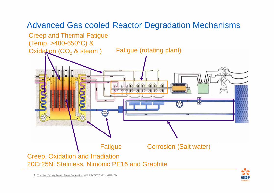
Advanced Gas cooled Reactor Degradation Mechanisms
Creep, Oxidation and Irradiation20Cr25Ni Stainless, Nimonic PE16 and Graphite
Creep and Thermal Fatigue (Temp. >400-650°C) & Oxidation (CO2 & steam )
Fatigue Corrosion (Salt water)
Fatigue (rotating plant)
The Use of Creep Data in Power Generation, NOT PROTECTIVELY MARKED3
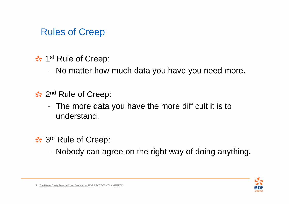
Rules of Creep
1st Rule of Creep:- No matter how much data you have you need more.
2nd Rule of Creep:- The more data you have the more difficult it is to
understand.
3rd Rule of Creep:- Nobody can agree on the right way of doing anything.

The Use of Creep Data in Power Generation, NOT PROTECTIVELY MARKED4
Engineering Disasters
‘Sultana’ Boiler explosion 27 April 1865,
1238 killed

The Use of Creep Data in Power Generation, NOT PROTECTIVELY MARKED5
Design Code Requirements for Creep DataASME II Part D and ASME VIII :- Stress to produce a creep rate of 0.01%/1000 h- Stress to cause rupture at the end of 100,000 h
- Base metal and appropriate weld metals and weldments at 50°C intervals and 50°C above the maximum intended use temperature.
ASME III-NH also requires:- Stress to a Total (elastic, plastic, primary, and secondary) Strain of 1%;- Stress to cause initiation of tertiary creep
IMechE Creep of Steels Working Party also provides- 0.1, 0.2, 0.5, 1, 2, 5% Creep Strain
BS EN 13445-3:2009- 1% Creep Strain- Rupture strength
RCC-MR- Time and creep strain at the end of primary, - min creep strain rate, - Time and creep strain at the initiation of tertiary.

The Use of Creep Data in Power Generation, NOT PROTECTIVELY MARKED6
Creep Testing Requirements for Design DataASME- Tests to 30,000 hours for extrapolation to 100,000 hours- Base metal and appropriate weld metals and weldments
at 50°C intervals and 50°C above the maximum intended use temperature.
TÜV - Min. 3 Casts Tested to 30,000hours
BS and European Standards, ISO 6303 and PD6605 and ECCC- x3 the test duration exceeded by data points from 5 Casts
at temperatures within 25°C of that specified- i.e. >70,000h testing for 200kh design- i.e. >80,000h testing for 250kh design

The Use of Creep Data in Power Generation, NOT PROTECTIVELY MARKED7
½CrMoV at 550°C
0
20
40
60
80
100
120
140
160
180
200
0 50000 100000 150000 200000 250000 300000 350000 400000Time (hours)
Stre
ss (M
Pa)
550°C PD6525 550°C
Beech 550°C AJB2 550°C
ISO 1978 550°C
End of life window (T 500 to 540°C)
The Use of Creep Data in Power Generation, NOT PROTECTIVELY MARKED8
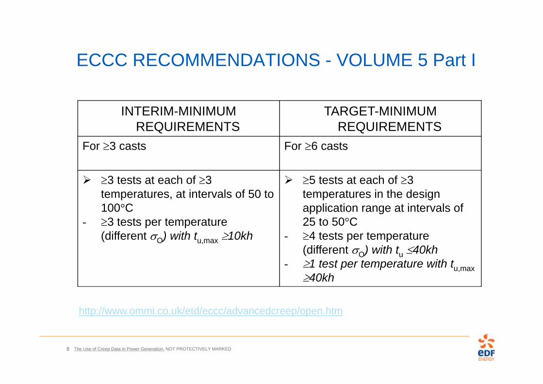
ECCC RECOMMENDATIONS - VOLUME 5 Part I
INTERIM-MINIMUM REQUIREMENTS
TARGET-MINIMUM REQUIREMENTS
For 3 casts For 6 casts
3 tests at each of 3 temperatures, at intervals of 50 to 100°C
- 3 tests per temperature (different O) with tu,max 10kh
5 tests at each of 3 temperatures in the design application range at intervals of 25 to 50°C
- 4 tests per temperature (different O) with tu 40kh
- 1 test per temperature with tu,max40kh
http://www.ommi.co.uk/etd/eccc/advancedcreep/open.htm
The Use of Creep Data in Power Generation, NOT PROTECTIVELY MARKED9
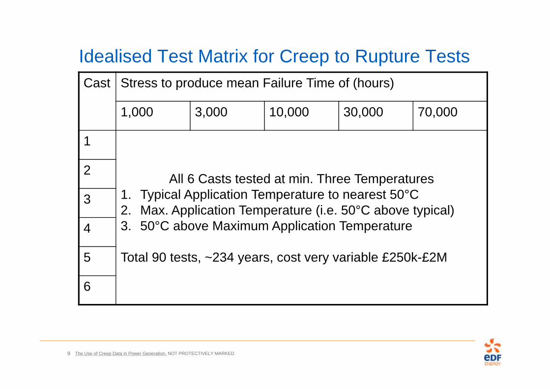
Idealised Test Matrix for Creep to Rupture TestsCast Stress to produce mean Failure Time of (hours)
1,000 3,000 10,000 30,000 70,000
1
All 6 Casts tested at min. Three Temperatures 1. Typical Application Temperature to nearest 50°C2. Max. Application Temperature (i.e. 50°C above typical)3. 50°C above Maximum Application Temperature
Total 90 tests, ~234 years, cost very variable £250k-£2M
2
3
4
5
6
The Use of Creep Data in Power Generation, NOT PROTECTIVELY MARKED10
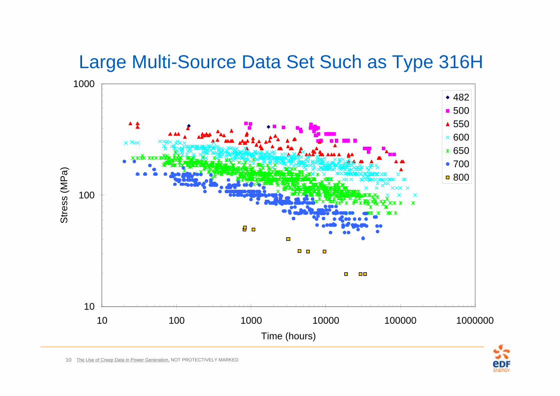
Large Multi-Source Data Set Such as Type 316H
10
100
1000
10 100 1000 10000 100000 1000000Time (hours)
Stre
ss (M
Pa)
482500550600650700800

The Use of Creep Data in Power Generation, NOT PROTECTIVELY MARKED11
Medium Single/Double Source Data Sets - NF709R
0
50
100
150
200
250
300
350
400
450
500
100 1000 10000 100000
Time (hours)
Line
ar S
tress
(Pro
prie
tary
Dat
a)
600°C 650°C 700°C 750°C800°C 600°C unfailed 650°C unfailed 700°C unfailed750°C unfailed 800°C unfailed 3S2T Model Multi-Region
The Use of Creep Data in Power Generation, NOT PROTECTIVELY MARKED12
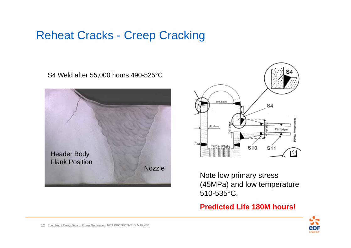
Reheat Cracks - Creep Cracking
Note low primary stress (45MPa) and low temperature 510-535°C.
Predicted Life 180M hours!
Header Body Flank Position
S4 Weld after 55,000 hours 490-525°C
Nozzle
The Use of Creep Data in Power Generation, NOT PROTECTIVELY MARKED13
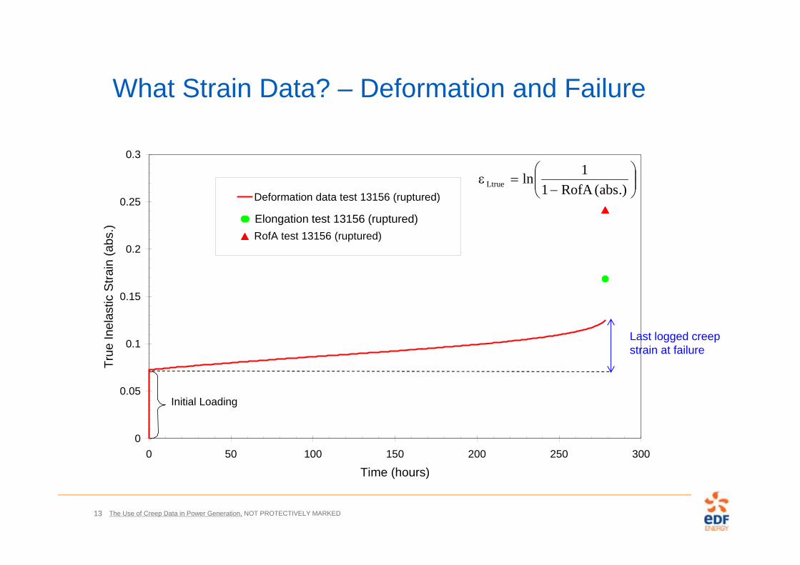
0
0.05
0.1
0.15
0.2
0.25
0.3
0 50 100 150 200 250 300
Time (hours)
True
Inel
astic
Stra
in (a
bs.)
Deformation data test 13156 (ruptured)
RofA test 13156 (ruptured)
Initial Loading
Elongation test 13156 (ruptured)
Last logged creep strain at failure
What Strain Data? – Deformation and Failure
.)abs(RofA1
1lnLtrue
The Use of Creep Data in Power Generation, NOT PROTECTIVELY MARKED14
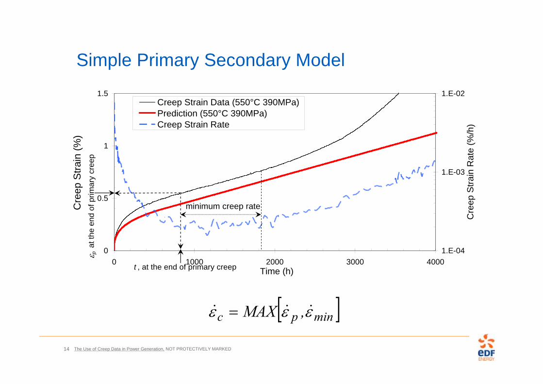
Simple Primary Secondary Model
0
0.5
1
1.5
0 1000 2000 3000 4000Time (h)
Cre
ep S
train
(%)
1.E-04
1.E-03
1.E-02
Cre
ep S
train
Rat
e (%
/h)
Creep Strain Data (550°C 390MPa)Prediction (550°C 390MPa)Creep Strain Rate
t , at the end of primary creep
minimum creep rate
p a
t the
end
of p
rimar
y cr
eep
minpc ,MAX
The Use of Creep Data in Power Generation, NOT PROTECTIVELY MARKED15
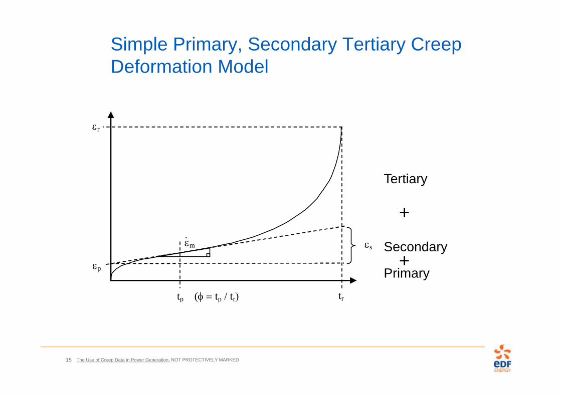
Simple Primary, Secondary Tertiary Creep Deformation Model
s
r
p
tp (tp / tr tr
m
Tertiary
Secondary
Primary
+
+
The Use of Creep Data in Power Generation, NOT PROTECTIVELY MARKED16
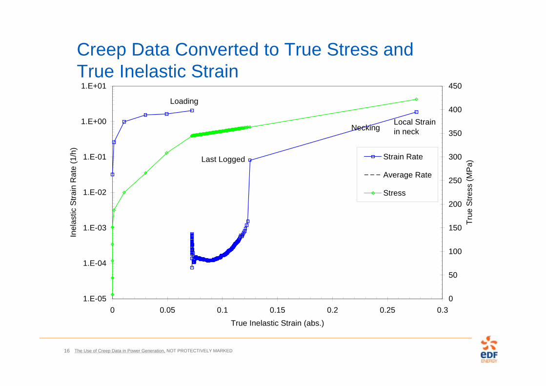
Creep Data Converted to True Stress and True Inelastic Strain
1.E-05
1.E-04
1.E-03
1.E-02
1.E-01
1.E+00
1.E+01
0 0.05 0.1 0.15 0.2 0.25 0.3True Inelastic Strain (abs.)
Inel
astic
Stra
in R
ate
(1/h
)
0
50
100
150
200
250
300
350
400
450
True
Stre
ss (M
Pa)
Strain Rate
Average Rate
Stress
Loading
Last Logged
NeckingLocal Strain in neck
The Use of Creep Data in Power Generation, NOT PROTECTIVELY MARKED17
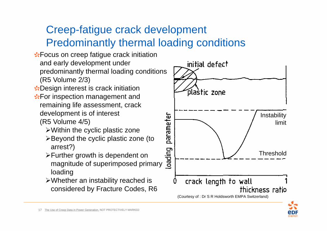
Creep-fatigue crack developmentPredominantly thermal loading conditions
Threshold
Instabilitylimit
Focus on creep fatigue crack initiation and early development under predominantly thermal loading conditions (R5 Volume 2/3)Design interest is crack initiationFor inspection management and remaining life assessment, crack development is of interest (R5 Volume 4/5)Within the cyclic plastic zoneBeyond the cyclic plastic zone (to
arrest?)Further growth is dependent on
magnitude of superimposed primary loadingWhether an instability reached is
considered by Fracture Codes, R6(Courtesy of : Dr S R Holdsworth EMPA Switzerland)

The Use of Creep Data in Power Generation, NOT PROTECTIVELY MARKED18
R5 Volume 2/3 Creep-fatigue crack initiation for defect free structuresThe integrity of a defect-free component is considered in Volume 2/3 by the following mechanisms:- Excessive plastic deformation- Creep rupture- Ratchetting or incremental collapse- Initiation of cracking due to combined creep and fatigue damage- Creep deformation enhanced by cyclic loadings
Design codes tend to use “elastic” calculations in the first instance, which are often excessively conservative. R5 Volume 2/3 uses “simplified inelastic analysis”, “reference stress” and “shakedown” concepts to give more realistic assessments while retaining some conservatism. R5 Volume 2/3 also allows “full inelastic analysis”.
The Use of Creep Data in Power Generation, NOT PROTECTIVELY MARKED19
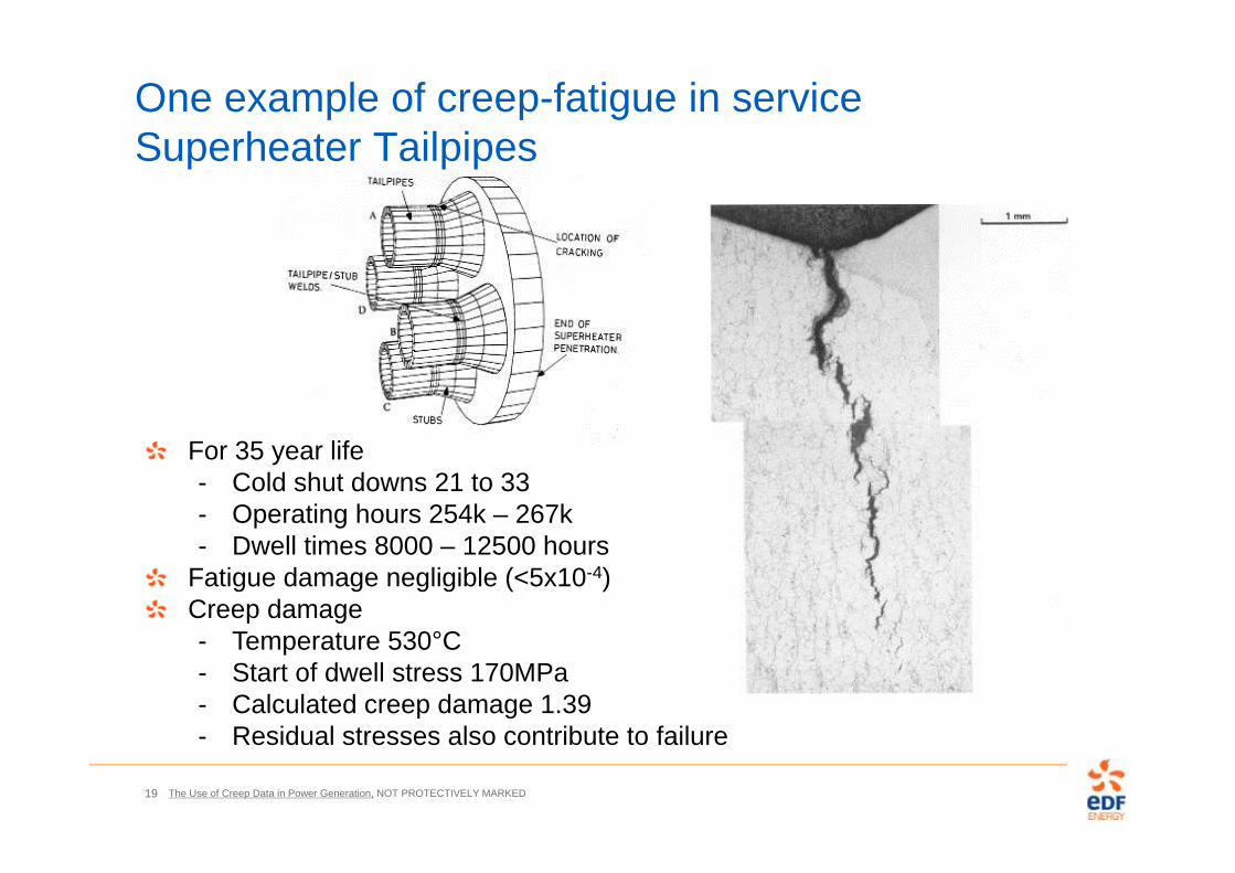
For 35 year life- Cold shut downs 21 to 33- Operating hours 254k – 267k - Dwell times 8000 – 12500 hours
Fatigue damage negligible (<5x10⁻⁴)Creep damage - Temperature 530°C- Start of dwell stress 170MPa- Calculated creep damage 1.39- Residual stresses also contribute to failure
One example of creep-fatigue in service Superheater Tailpipes
The Use of Creep Data in Power Generation, NOT PROTECTIVELY MARKED20
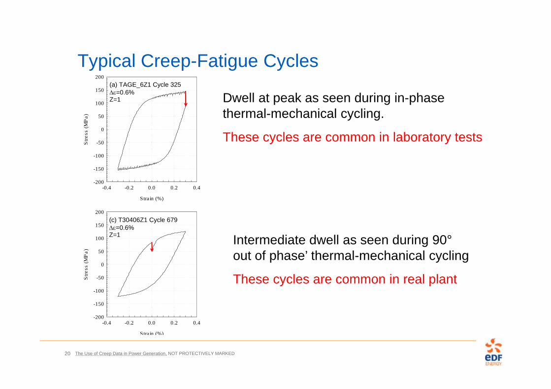
Typical Creep-Fatigue Cycles
Stra in (%)
-0.4 -0.2 0.0 0.2 0.4
Stre
ss (M
Pa)
-200
-150
-100
-50
0
50
100
150
200(c) T30406Z1 Cycle 679=0.6%Z=1
Stra in (%)
-0.4 -0.2 0.0 0.2 0.4
Stre
ss (M
Pa)
-200
-150
-100
-50
0
50
100
150
200(a) TAGE_6Z1 Cycle 325=0.6%Z=1 Dwell at peak as seen during in-phase
thermal-mechanical cycling.
These cycles are common in laboratory tests
Intermediate dwell as seen during 90°out of phase’ thermal-mechanical cycling
These cycles are common in real plant
The Use of Creep Data in Power Generation, NOT PROTECTIVELY MARKED21
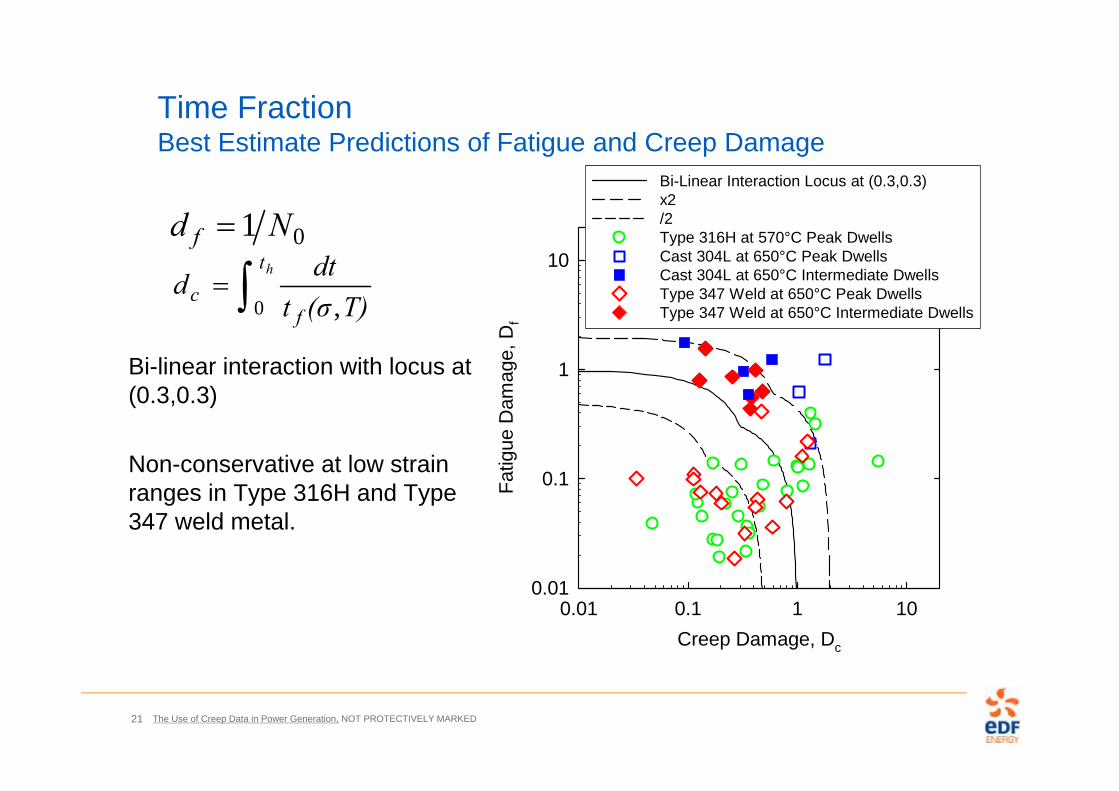
Time Fraction Best Estimate Predictions of Fatigue and Creep Damage
Bi-linear interaction with locus at (0.3,0.3)
Non-conservative at low strain ranges in Type 316H and Type 347 weld metal.
ht
fc T)(σt
dtd0 ,
01 Nd f
Creep Damage, Dc
0.01 0.1 1 10
Fatig
ue D
amag
e, D
f
0.01
0.1
1
10
Bi-Linear Interaction Locus at (0.3,0.3)x2/2Type 316H at 570°C Peak DwellsCast 304L at 650°C Peak DwellsCast 304L at 650°C Intermediate DwellsType 347 Weld at 650°C Peak DwellsType 347 Weld at 650°C Intermediate Dwells

The Use of Creep Data in Power Generation, NOT PROTECTIVELY MARKED22
Stress Modified Ductility Exhaustion (SMDE)Best Estimate Predictions of Fatigue and Creep Damage
Linear interaction
Decreased scatter about linear interaction for all tests.
Particularly, intermediate dwells Type 347 weld metal and Cast 304L and low strain ranges all materials.
Creep Damage, Dc
0.01 0.1 1 10
Fatig
ue D
amag
e, D
f
0.01
0.1
1
10
Linear Interactionx2/2Type 316H at 570°C Peak DwellsCast 304L at 650°C Peak DwellsCast 304L at 650°C Intermediate DwellsType 347 Weld at 650°C Peak DwellsType 347 Weld at 650°C Intermediate Dwells
dtT
dht
inf
inSMc
0),,(
11exp. mninf TPA

The Use of Creep Data in Power Generation, NOT PROTECTIVELY MARKED23
Local Strain at Failure
Elongation =39.3%
RofA =74.4%
Ltrue =148.6% (ln(1/(1-RofA(abs.)))
1
10
100
1000
1.E-08 1.E-07 1.E-06 1.E-05 1.E-04 1.E-03 1.E-02 1.E-01 1.E+00
Creep Strain Rate (1/h)
Duc
tility
(%)
True Local 100MPaElong. 100MPaTrue Local 201MPaElong. 201MPa True Local
Elongation

The Use of Creep Data in Power Generation, NOT PROTECTIVELY MARKED24
1
10
100
1000
0.0000001 0.000001 0.00001 0.0001 0.001 0.01 0.1
Average Strain Rate (1/h)
True
Loc
al S
train
(%)
116 to 185201 to 247278 to 312324 to 401Fit 151Fit 224Fit 295Fit 372
Stress (MPa)
Fitting Creep Ductility Data
111
1, exp mncUf T
PAMIN
The Use of Creep Data in Power Generation, NOT PROTECTIVELY MARKED25
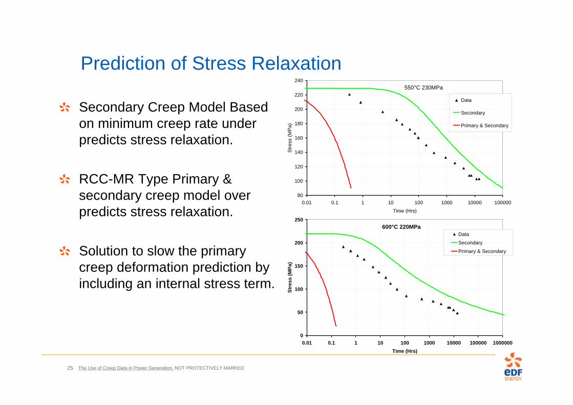
Prediction of Stress Relaxation
Secondary Creep Model Based on minimum creep rate under predicts stress relaxation.
RCC-MR Type Primary & secondary creep model over predicts stress relaxation.
Solution to slow the primary creep deformation prediction by including an internal stress term.
600°C 220MPa
0
50
100
150
200
250
0.01 0.1 1 10 100 1000 10000 100000 1000000Time (Hrs)
Stre
ss (M
Pa)
Data
Secondary
Primary & Secondary
550°C 230MPa
80
100
120
140
160
180
200
220
240
0.01 0.1 1 10 100 1000 10000 100000Time (Hrs)
Stre
ss (M
Pa)
Data
Secondary
Primary & Secondary
The Use of Creep Data in Power Generation, NOT PROTECTIVELY MARKED26
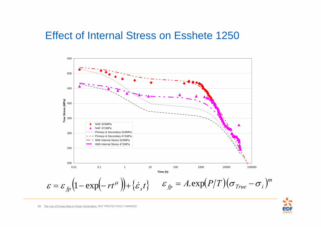
Effect of Internal Stress on Esshete 1250
200
250
300
350
400
450
500
550
0.01 0.1 1 10 100 1000 10000 100000
Time (h)
True
Str
ess
(MPa
)
NAE 523MPaNAF 471MPaPrimary & Secondary 523MPaPrimary & Secondary 471MPaWith Internal Stress 523MPaWith Internal Stress 471MPa
trt sfp exp1 miTruefp TPA exp.
The Use of Creep Data in Power Generation, NOT PROTECTIVELY MARKED27
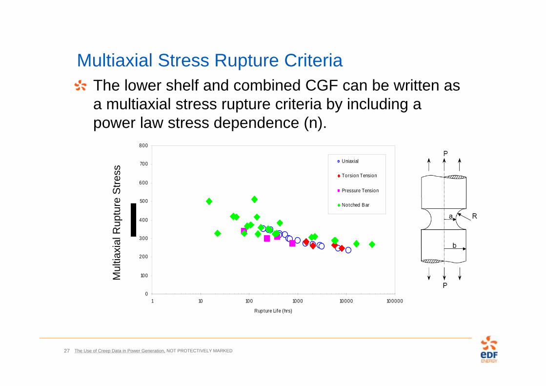
Multiaxial Stress Rupture CriteriaThe lower shelf and combined CGF can be written as a multiaxial stress rupture criteria by including a power law stress dependence (n).
0
100
200
300
400
500
600
700
800
1 10 100 1000 10000 100000
Rupture Life (hrs)
Uniaxial
Torsion Tension
Pressure Tension
Notched Bar
Mul
tiaxi
al R
uptu
re S
tress

The Use of Creep Data in Power Generation, NOT PROTECTIVELY MARKED28
Plant States of Stress
0.333
0.417
0.500
0.583
0.667
0.5 1 1.5 2 2.51/equ
S 1/
equ
Notched Bars a/R=0.53 to 25
Biaxial
Plant Experience
Region where tests are needed
Max Principal/von Mises Stress
Dev
iato
ric/v
on M
ises
Stre
ss
The Use of Creep Data in Power Generation, NOT PROTECTIVELY MARKED29
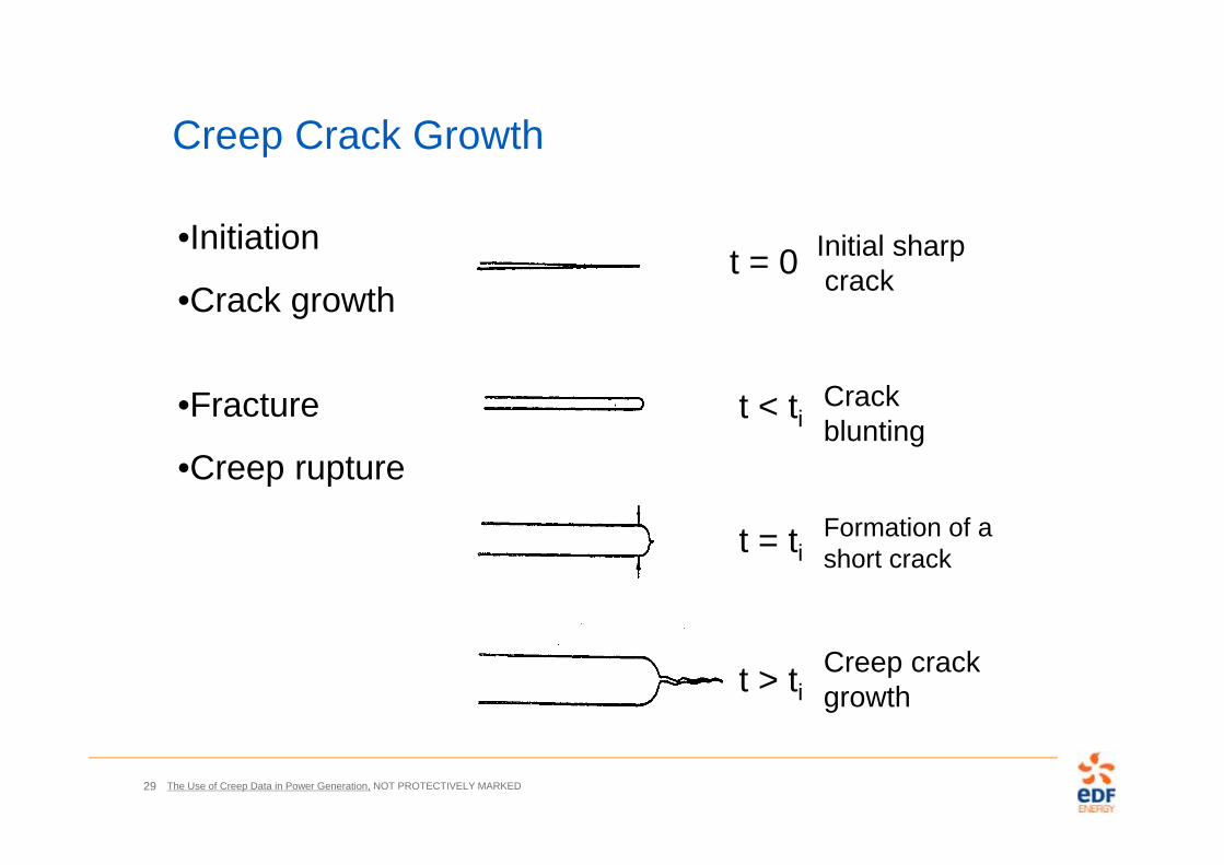
Creep Crack Growth
t > ti
t = ti
t < ti
t = 0 Initial sharpcrack
Crack blunting
Formation of ashort crack
Creep crackgrowth
•Initiation
•Crack growth
•Fracture
•Creep rupture
The Use of Creep Data in Power Generation, NOT PROTECTIVELY MARKED30
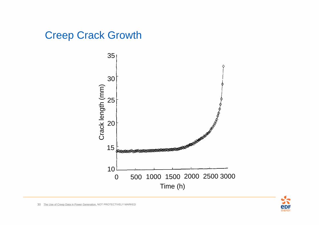
Creep Crack Growth
0 500 1000 1500 2000 2500 300010
15
20
25
30
35
Time (h)
Cra
ck le
ngth
(mm
)
The Use of Creep Data in Power Generation, NOT PROTECTIVELY MARKED31
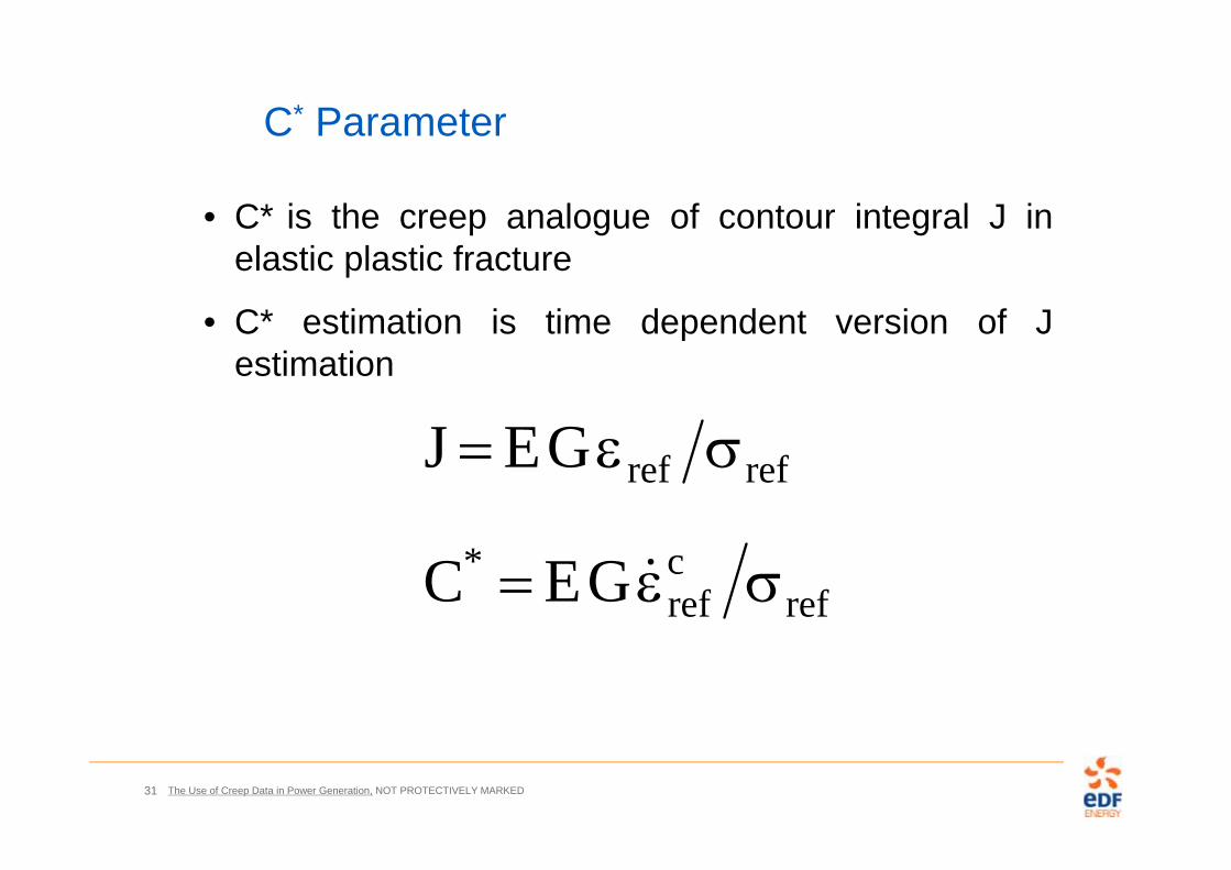
• C* is the creep analogue of contour integral J inelastic plastic fracture
• C* estimation is time dependent version of Jestimation
C* Parameter
refcref
*
refref
GEC
GEJ

The Use of Creep Data in Power Generation, NOT PROTECTIVELY MARKED32
Creep Crack Growth Testing
0 500 1000 1500 2000 2500 3000 3500
0.2
0.4
0.6
0.8
1Load line displacement (mm)
Hours
0 500 1000 1500 2000 2500 3000 3500
0.5
1
1.5
2
2.5
3
Hours
Crack growth (mm)
20 amp DC
32mm
p.d.output
50mm
p.d.output
p.d.output
4mm
Potentialmeasurementpoints
Displacement transducer(lvdt)

The Use of Creep Data in Power Generation, NOT PROTECTIVELY MARKED33
Creep Crack Growth Data
1E-07
1E-06
1E-05
1E-04
1E-03
1E-06 1E-05 1E-04 1E-03
C* [MPa m/h]
da/d
t [m
/h]
Sepc. 01Spec. 07cSpec. 08Spec. 10Spec. 15Spec. 14R66 UB: A=0.5Base Line Creep: A=0.2R66 Mean: A=0.1
R66 Mean
R66 Mean x 2
R66 Upper Bound
qACa *
Decreasing Ductility
Increasing Creep Rate
The Use of Creep Data in Power Generation, NOT PROTECTIVELY MARKED34
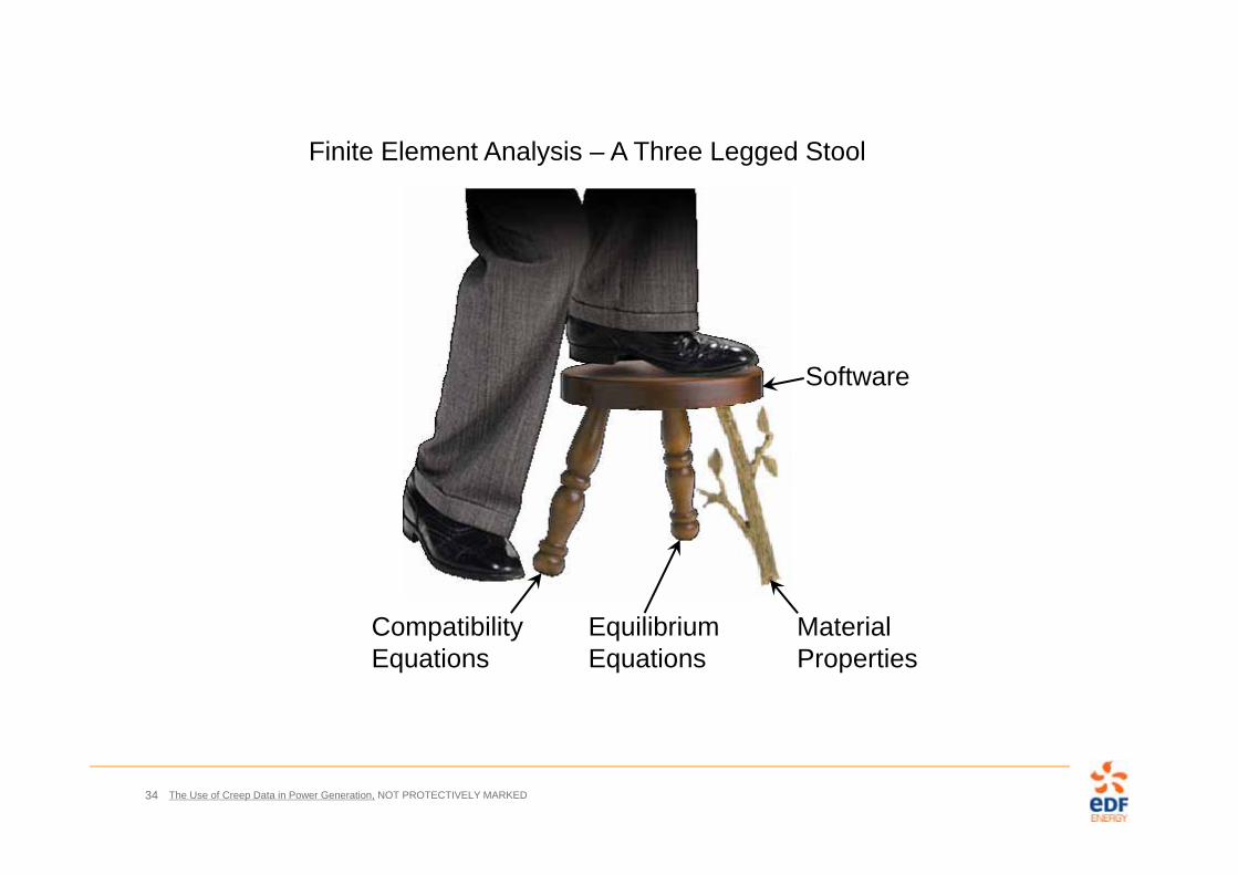
Finite Element Analysis – A Three Legged Stool
Software
Compatibility Equations
Equilibrium Equations
Material Properties
The Use of Creep Data in Power Generation, NOT PROTECTIVELY MARKED35
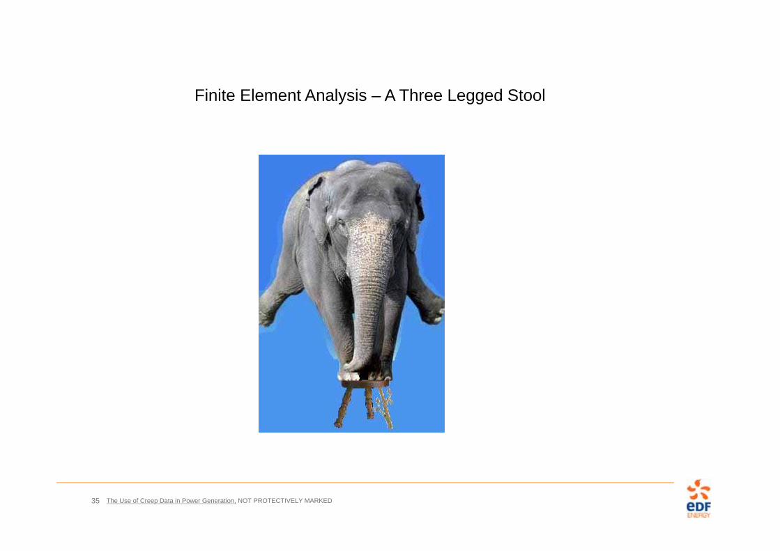
Finite Element Analysis – A Three Legged Stool


![HIGH-TEMPERATURE EXPERIMENTAL ......hardening [4] and power law (Norton) creep is used to model the creep deformation during the dwell period of each forming cycle. Cyclic plasticity](https://img.pdfslide.net/doc/110x75/5fc43384d5073f285b2220ba/high-temperature-experimental-hardening-4-and-power-law-norton-creep.jpg)