Embed Size (px)
Citation preview
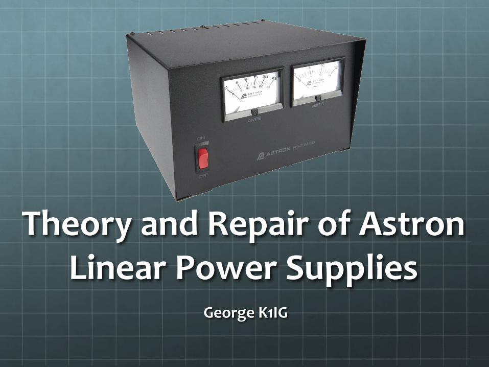
Theory and Repair of AstronLinear Power Supplies
George K1IG
TopicsLinear Power Supplies
Astron Observations
Block Diagrams
Components
Electrical Safety
Troubleshooting & Repair
Test & Calibration
Efficiency & Noise Measurements
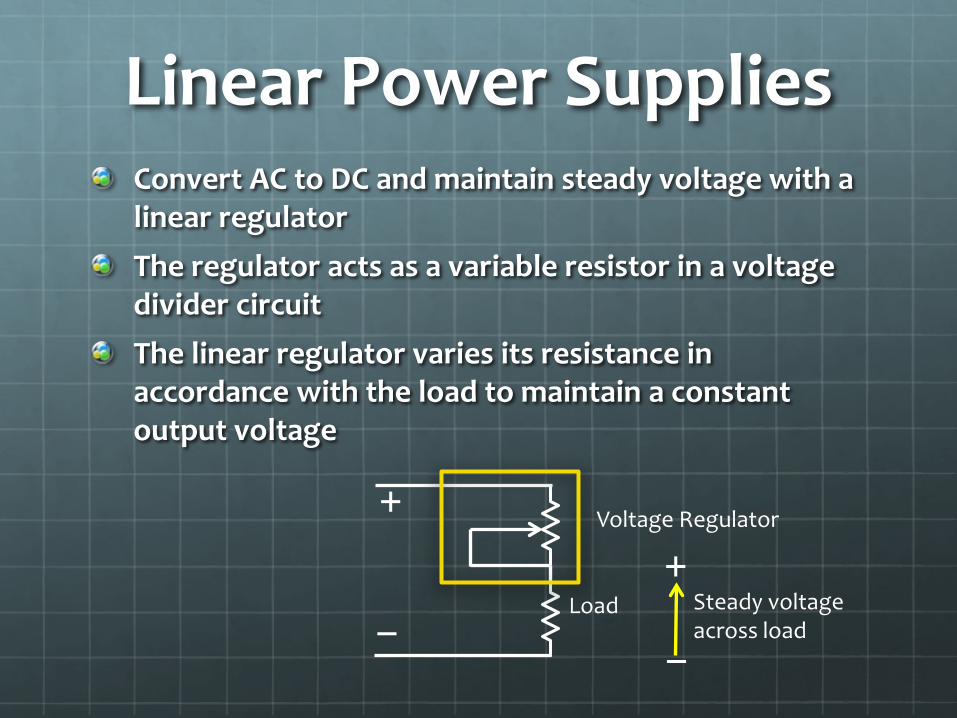
Linear Power SuppliesConvert AC to DC and maintain steady voltage with a linear regulatorThe regulator acts as a variable resistor in a voltage divider circuit The linear regulator varies its resistance in accordance with the load to maintain a constant output voltage
Load
Voltage Regulator+
− −
+Steady voltage across load

Astron ObservationsLongevity
Family of RS supplies – all the same design
Simple and inexpensive to repair
No configuration control; circuit diagrams are sometimes incorrect
No help on Astron web site
Lots of help on www.repeater-builder.com
Electrical safety hazards

Astron RS Block Diagram
Voltage Regulator
120 VAC
13.8 VDC
Crowbar
28 VDC
28 VAC
Pass Transistors
+
LM 723
+
−
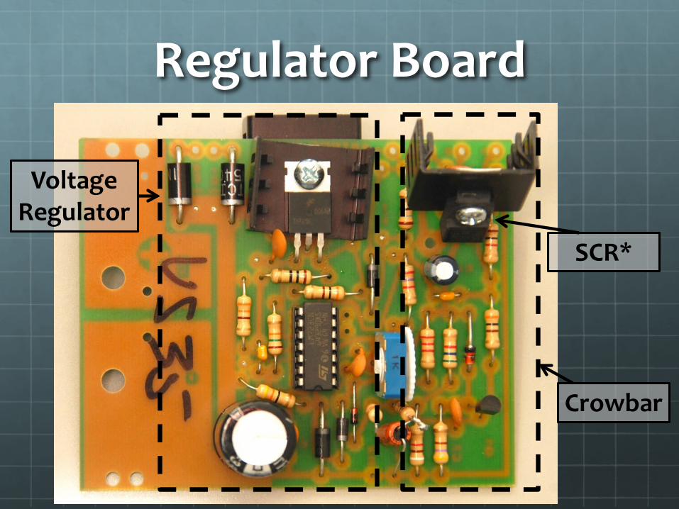
Regulator Board
Voltage Regulator
Crowbar
SCR*
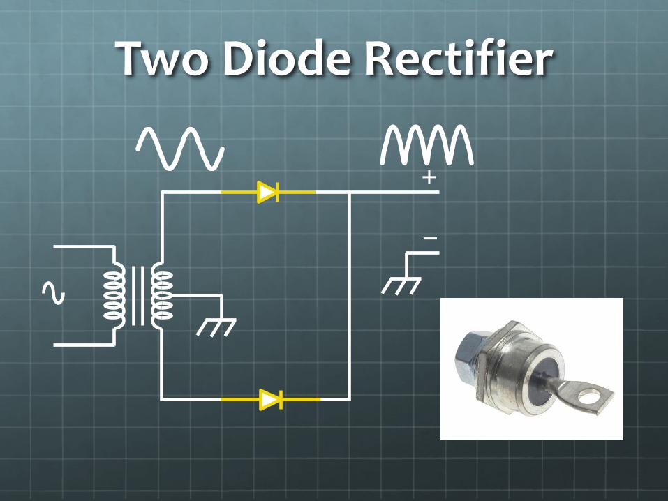
Two Diode Rectifier
+
−

Bridge Rectifier
+
−
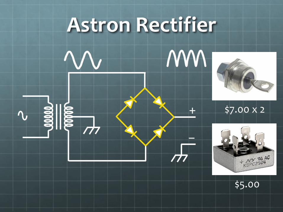
Astron Rectifier
+
−
$7.00 x 2
$5.00
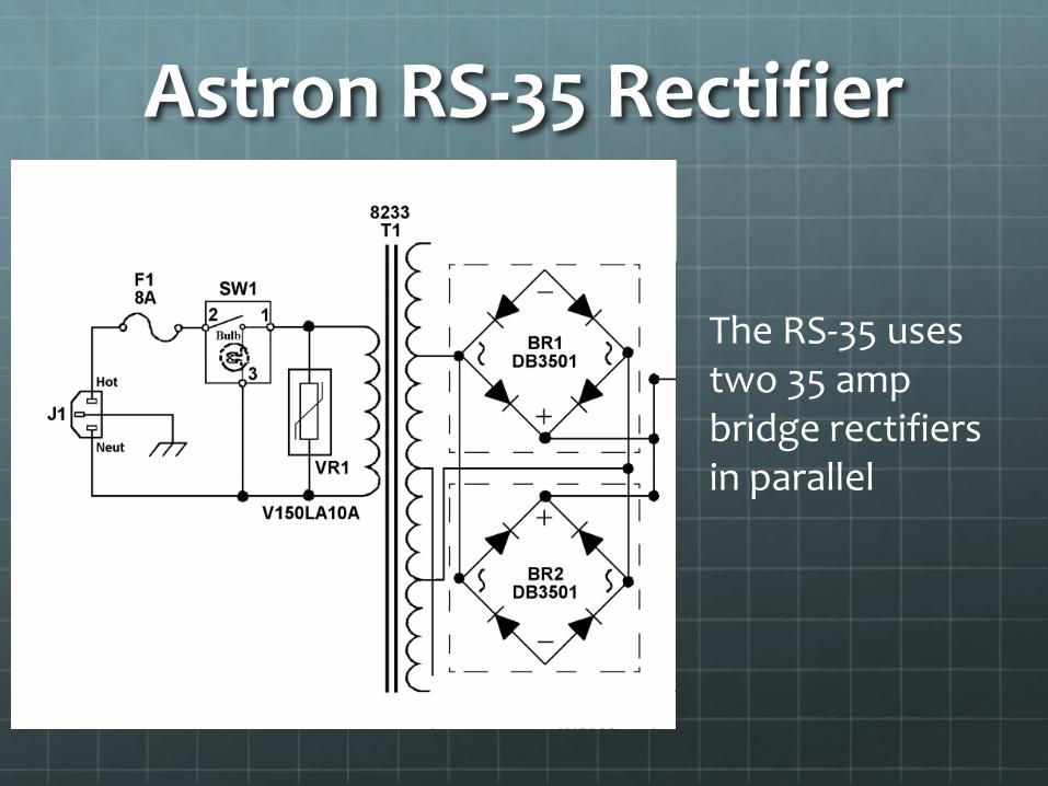
Astron RS-35 Rectifier
The RS-35 uses two 35 amp bridge rectifiers in parallel

Astron RS-35M

Electrical SafetyExposed voltages
28 VDC
12

Electrical Safety
13.8 VDC
Fixes
Relocate diodes and SCR to the inside of the cabinet
Cover them upTapeHeat shrink
Exposed voltages
13

Floating Ground?
Astron is inconsistent – some do, and some don’tDon’t rely on the circuit diagram; check it yourselfDoes it matter?
+
−
Floating
+
−
Non-Floating

Floating GroundElecraft: “We don't recommend a floating ground. If you insist on trying it, at the minimum you should fuse the + and − leads with 25 Amp fast blow fuses.”
Icom: “The issue is most devices that have a floating ground will short out if the negative lead touches its chassis or create a ground loop. The radio negative DC IN wire is also at the chassis (not floating) so if you tie the power supply chassis with floating ground and the radio chassis to ground you could be shorting out the power supply letting the smoke out of it and possibly the radio also.”
Don’t Float

TroubleshootingThink of the power supply as five modules
Transformer Rectifier Filter Capacitor
Pass Transistors
Regulator Board

TroubleshootingJust two symptoms1. It blows a fuse when you turn it on2. The output isn’t what it’s supposed to be
Too highToo lowDrops under loadHum
We’ll only look at most common causes
Only a volt-ohmmeter for test equipment

Blows A FuseThe most common problem in the RS-35
Design flaw
18

Blows A FuseTroubleshooting
Disconnect wires
Test resistance
Replace with a single bridge rectifier
19

Blows A FuseReplacing
Verify polarity
Use thermal compound

Bad Output
Could be:Filter capacitor (rare)Pass transistor(s) Regulator board
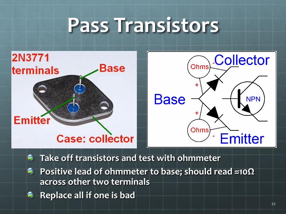
Pass Transistors
Take off transistors and test with ohmmeterPositive lead of ohmmeter to base; should read ≈10Ω across other two terminalsReplace all if one is bad
22
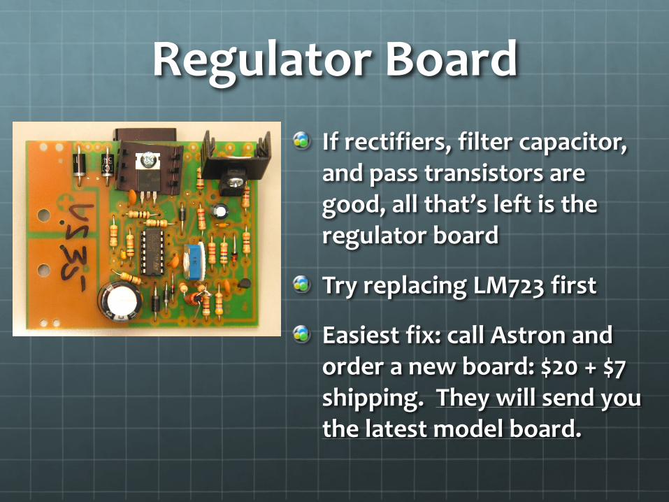
Regulator BoardIf rectifiers, filter capacitor, and pass transistors are good, all that’s left is the regulator board
Try replacing LM723 first
Easiest fix: call Astron and order a new board: $20 + $7 shipping. They will send you the latest model board.

Regulator Board Replacement
Label all the wires and mark the connections on the old and new boards before you remove the old board. Don’t rely on the circuit diagram.
Take pictures before unsoldering the old board
Don’t mess with the potentiometer
If your power supply has the SCR off the board, consult “Installing a New Regulator Board in an Old Astron Power Supply” on the Repeater-Builder website
24
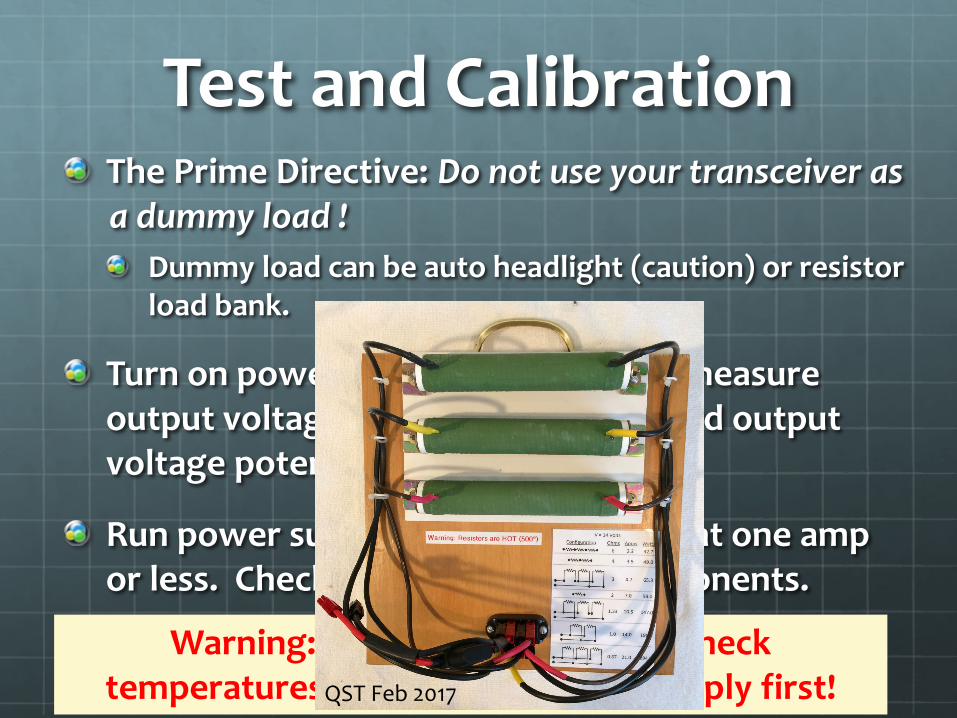
Test and CalibrationDo not use your transceiver as
a dummy load !The Prime Directive:
Dummy load can be auto headlight (caution) or resistor load bank.
Turn on power supply (no load) and measure output voltage. Adjust regulator board output voltage potentiometer if necessary.
Run power supply for about an hour at one amp or less. Check for hot and cold components.
Cold: bad componentHot: bad component or heat sink problem
Warning: If using your finger to check temperatures, turn off the power supply first! QST Feb 2017

Test and CalibrationRun power supply at increased loads for a few minutes.
Check for hot/cold components at each load incrementCheck voltage stabilityCheck power supply voltmeter and ammeter calibrations. Adjust with plastic tool.
GET ON THE AIR!

Power Supply Efficiency
We can compare efficiency of the linear versus switched-mode power supplies
Efficiency = Output PowerInput Power
x 100%

Power Supply Efficiency

QST Product Review
QST, Feb 2012

Noise Measurements

Switching PS Noise
Synthesizer?
On Power Supply
On Battery
S0
P.S. Signal
S4
Broadband Noise
dBm