Embed Size (px)
Citation preview
USER MANUALTHERA-TRAINER BALO
English translation of original user manual
( BALANCE-TRAINER)
Congratulations!
Opting for a THERA-Trainer was a great choice. This innovative movement exerciser offers top perfor-mance „Made in Germany“.
This user manual will help you get to know your THERA-Trainer better. It will safely guide you through allfunctions and control options and provide you with tips and information on how to use your new exerciserbest.
Before starting the unit for the first time, please read and observe chapter 2 “Safety and dangers”.
Should you have any questions or suggestions, your local specialist dealer will be happy to help.
Have fun and get moving with your THERA-Trainer.
THERA-TRAINER BALOUSER MANUAL
2 Art. no.: A002-565Version: 04/2013
3Art. no: A002-565Version: 04/2013
THERA-TRAINER BALOUSER MANUAL
1 USER GUIDE . . . . . . . . . . . . . . . . . . . . . . . . . . . . . . . . . . . . . . . . . . . . . . . . . . . . . . . . . . . . . . . . . . 41.1 Warning notices . . . . . . . . . . . . . . . . . . . . . . . . . . . . . . . . . . . . . . . . . . . . . . . . . . . . . . . . . . . . . . . . 41.2 Notes . . . . . . . . . . . . . . . . . . . . . . . . . . . . . . . . . . . . . . . . . . . . . . . . . . . . . . . . . . . . . . . . . . . . . . . . 41.3 Symbols in the user manual . . . . . . . . . . . . . . . . . . . . . . . . . . . . . . . . . . . . . . . . . . . . . . . . . . . . . . . 41.4 Symbols on the product . . . . . . . . . . . . . . . . . . . . . . . . . . . . . . . . . . . . . . . . . . . . . . . . . . . . . . . . . . 5
2 SAFETY AND DANGERS . . . . . . . . . . . . . . . . . . . . . . . . . . . . . . . . . . . . . . . . . . . . . . . . . . . . . . . . 6
3 INTENDED USE. . . . . . . . . . . . . . . . . . . . . . . . . . . . . . . . . . . . . . . . . . . . . . . . . . . . . . . . . . . . . . . . 73.1 Indications . . . . . . . . . . . . . . . . . . . . . . . . . . . . . . . . . . . . . . . . . . . . . . . . . . . . . . . . . . . . . . . . . . . . 73.2 Biocompatibility. . . . . . . . . . . . . . . . . . . . . . . . . . . . . . . . . . . . . . . . . . . . . . . . . . . . . . . . . . . . . . . . . 7
4 FORESEEABLE MISUSE . . . . . . . . . . . . . . . . . . . . . . . . . . . . . . . . . . . . . . . . . . . . . . . . . . . . . . . . 74.1 Contraindications . . . . . . . . . . . . . . . . . . . . . . . . . . . . . . . . . . . . . . . . . . . . . . . . . . . . . . . . . . . . . . . 84.2 Misuse . . . . . . . . . . . . . . . . . . . . . . . . . . . . . . . . . . . . . . . . . . . . . . . . . . . . . . . . . . . . . . . . . . . . . . . 8
5 SCOPE OF DELIVERY AND DESCRIPTION OF DE-LIVERED EQUIPMENT . . . . . . . . . . . . . . . 95.1 Scope of delivery . . . . . . . . . . . . . . . . . . . . . . . . . . . . . . . . . . . . . . . . . . . . . . . . . . . . . . . . . . . . . . . 95.2 Basic equipment . . . . . . . . . . . . . . . . . . . . . . . . . . . . . . . . . . . . . . . . . . . . . . . . . . . . . . . . . . . . . . . . 95.3 Options . . . . . . . . . . . . . . . . . . . . . . . . . . . . . . . . . . . . . . . . . . . . . . . . . . . . . . . . . . . . . . . . . . . . . . . 9
6 OVERVIEW . . . . . . . . . . . . . . . . . . . . . . . . . . . . . . . . . . . . . . . . . . . . . . . . . . . . . . . . . . . . . . . . . . 10
7 START-UP . . . . . . . . . . . . . . . . . . . . . . . . . . . . . . . . . . . . . . . . . . . . . . . . . . . . . . . . . . . . . . . . . . . 117.1 Unpacking. . . . . . . . . . . . . . . . . . . . . . . . . . . . . . . . . . . . . . . . . . . . . . . . . . . . . . . . . . . . . . . . . . . . 117.2 Installation of THERA-Trainer balo. . . . . . . . . . . . . . . . . . . . . . . . . . . . . . . . . . . . . . . . . . . . . . . . . 117.3 Transport of THERA-Trainer balo. . . . . . . . . . . . . . . . . . . . . . . . . . . . . . . . . . . . . . . . . . . . . . . . . . 13
8 OPERATION . . . . . . . . . . . . . . . . . . . . . . . . . . . . . . . . . . . . . . . . . . . . . . . . . . . . . . . . . . . . . . . . . 148.1 Preparation for training . . . . . . . . . . . . . . . . . . . . . . . . . . . . . . . . . . . . . . . . . . . . . . . . . . . . . . . . . . 148.2 Safety devices . . . . . . . . . . . . . . . . . . . . . . . . . . . . . . . . . . . . . . . . . . . . . . . . . . . . . . . . . . . . . . . . 24
9 CONTROL . . . . . . . . . . . . . . . . . . . . . . . . . . . . . . . . . . . . . . . . . . . . . . . . . . . . . . . . . . . . . . . . . . . 259.1 Control elements . . . . . . . . . . . . . . . . . . . . . . . . . . . . . . . . . . . . . . . . . . . . . . . . . . . . . . . . . . . . . . 259.2 Electric lift . . . . . . . . . . . . . . . . . . . . . . . . . . . . . . . . . . . . . . . . . . . . . . . . . . . . . . . . . . . . . . . . . . . . 259.3 Lifting and lowering without electric lift . . . . . . . . . . . . . . . . . . . . . . . . . . . . . . . . . . . . . . . . . . . . . . 289.4 Starting up the control and display unit . . . . . . . . . . . . . . . . . . . . . . . . . . . . . . . . . . . . . . . . . . . . . 29
10 CLEANING AND DISINFECTION . . . . . . . . . . . . . . . . . . . . . . . . . . . . . . . . . . . . . . . . . . . . . . . . . 31
11 MAINTENANCE AND REPAIR . . . . . . . . . . . . . . . . . . . . . . . . . . . . . . . . . . . . . . . . . . . . . . . . . . . 3211.1 Replacing the balance unit . . . . . . . . . . . . . . . . . . . . . . . . . . . . . . . . . . . . . . . . . . . . . . . . . . . . . . . 3211.2 Replacing the patient belt with leg straps and bottom enlarged . . . . . . . . . . . . . . . . . . . . . . . . . . . 3211.3 Replacing the fuse . . . . . . . . . . . . . . . . . . . . . . . . . . . . . . . . . . . . . . . . . . . . . . . . . . . . . . . . . . . . . 3211.4 Further use . . . . . . . . . . . . . . . . . . . . . . . . . . . . . . . . . . . . . . . . . . . . . . . . . . . . . . . . . . . . . . . . . . . 32
12 TECHNICAL DATA . . . . . . . . . . . . . . . . . . . . . . . . . . . . . . . . . . . . . . . . . . . . . . . . . . . . . . . . . . . . 33
13 STANDARDS AND LAWS. . . . . . . . . . . . . . . . . . . . . . . . . . . . . . . . . . . . . . . . . . . . . . . . . . . . . . . 33
14 DISPOSAL . . . . . . . . . . . . . . . . . . . . . . . . . . . . . . . . . . . . . . . . . . . . . . . . . . . . . . . . . . . . . . . . . . . 33
15 NOTES ON ELECTROMAGNETIC COMPATIBILITY . . . . . . . . . . . . . . . . . . . . . . . . . . . . . . . . . 3415.1 Lines, line lengths and accessories . . . . . . . . . . . . . . . . . . . . . . . . . . . . . . . . . . . . . . . . . . . . . . . . 3415.2 Warning notice regarding installation . . . . . . . . . . . . . . . . . . . . . . . . . . . . . . . . . . . . . . . . . . . . . . . 3415.3 Level of conformity . . . . . . . . . . . . . . . . . . . . . . . . . . . . . . . . . . . . . . . . . . . . . . . . . . . . . . . . . . . . . 3415.4 Electromagnetic emission. . . . . . . . . . . . . . . . . . . . . . . . . . . . . . . . . . . . . . . . . . . . . . . . . . . . . . . . 3415.5 Immunity . . . . . . . . . . . . . . . . . . . . . . . . . . . . . . . . . . . . . . . . . . . . . . . . . . . . . . . . . . . . . . . . . . . . . 3515.6 Recommended protective distances between portable and mobile HF telecommunication devices
and THERA-Trainer balo . . . . . . . . . . . . . . . . . . . . . . . . . . . . . . . . . . . . . . . . . . . . . . . . . . . . . . . . 37
16 WARRANTY. . . . . . . . . . . . . . . . . . . . . . . . . . . . . . . . . . . . . . . . . . . . . . . . . . . . . . . . . . . . . . . . . . 37
THERA-TRAINER BALOUSER MANUAL
4 Art. no: A002-565Version: 04/2013
1 USER GUIDE
User manual and product are labelled with symbols. The symbols and theirfunctions make it easier to use the product safely and efficiently.
1.1 Warning notices
Classification of warning notices
There are different types of warning notices indicated by the following signal words depending on the type of danger:
Caution warns about the risk of material damage. Warning warns about the risk of physical injury. Danger warns about the risk of fatal injury.
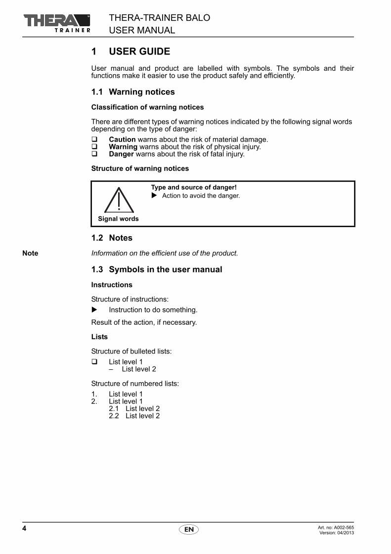
Structure of warning notices
1.2 Notes
Note Information on the efficient use of the product.
1.3 Symbols in the user manual
Instructions
Structure of instructions:
Instruction to do something.
Result of the action, if necessary.
Lists
Structure of bulleted lists:
List level 1– List level 2
Structure of numbered lists:
1. List level 12. List level 1
2.1 List level 22.2 List level 2
Signal words
Type and source of danger! Action to avoid the danger.
5Art. no: A002-565Version: 04/2013
THERA-TRAINER BALOUSER MANUAL
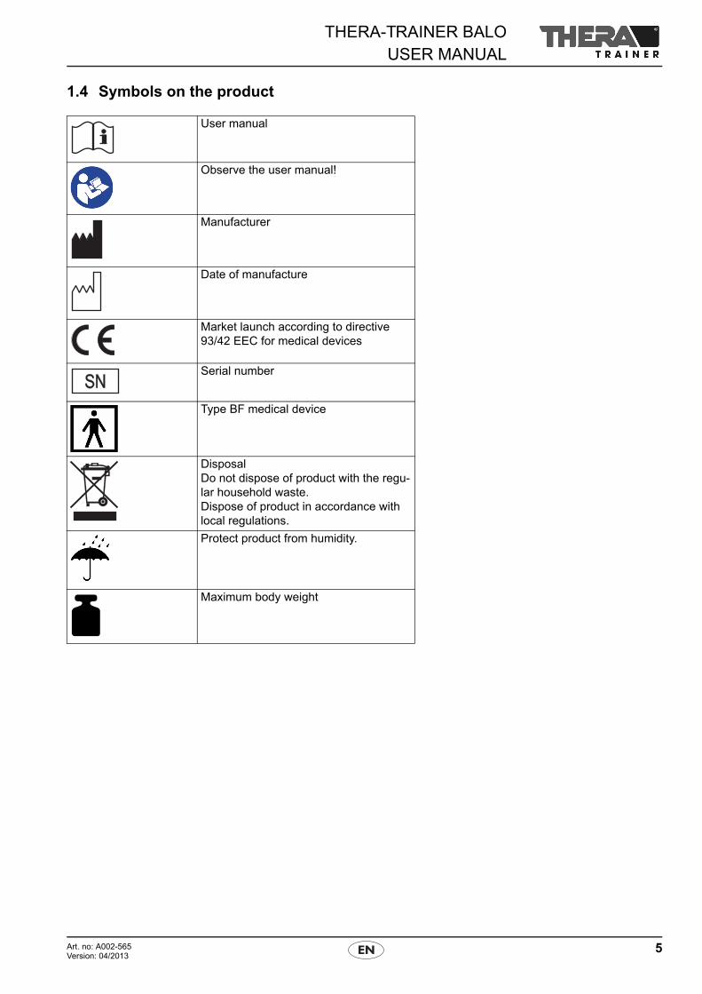
1.4 Symbols on the product
User manual
Observe the user manual!
Manufacturer
Date of manufacture
Market launch according to directive 93/42 EEC for medical devices
Serial number
Type BF medical device
DisposalDo not dispose of product with the regu-lar household waste.Dispose of product in accordance with local regulations.
Protect product from humidity.
Maximum body weight
THERA-TRAINER BALOUSER MANUAL
6 Art. no: A002-565Version: 04/2013
2 SAFETY AND DANGERS
Observe the user manual. Use THERA-Trainer balo exclusively in good and functional condition. Regularly check tightness of screws. Prior to the initial start-up, have your trained dealer, doctor or therapist show
you how to use the product. Put THERA-Trainer balo on even and slip-proof floor. Keep sufficient distance between THERA-Trainer balo and any walls and
obstacles. Always wear closed shoes when training (both user and assistant). Always use THERA-Trainer balo with knee support set and pelvic support set. Before getting in, make sure that all transport castors with brake are blocked. Block balance function before getting in. Exercise exclusively under supervision of a trained assistant. Do not use THERA-Trainer balo in wet, humid or hot environments. Have exclusively trained dealers do any repair or maintenance work. In case of damage, malfunctions, etc. of the THERA-Trainer balo, contact a
trained dealer immediately. Consult the manufacturer before any modification and modify
THERA-Trainer balo exclusively with the manufacturer's approval. Disinfect THERA-Trainer balo before every training. Do not smoke while exercising. Make sure that THERA-Trainer balo does not get wet. Do not use THERA-Trainer balo to transport persons. If any symptoms of illness occur during or after training, seek medical advice
immediately. Make sure that buckle tongues audibly click into place in belt buckles. Make sure that SAFETY-STOP button is easily accessible for user and
trained assistant at all times. When laying cables, make sure that
– the user's movements are not limited.– the movements of the THERA-Trainer balo are not limited.– there is no risk of persons falling over or being limited by cables.
Use the manufacturer's original parts exclusively. Use THERA-Trainer balo and battery charger exclusively with undamaged
and functional cables. Take care not to pinch any fingers when adjusting settings (e. g. height of
table unit) on THERA-Trainer balo. Electric lift of THERA-Trainer balo:
– use exclusively with correctly set supply voltage.– do not use continuously (maximum 10 lifts within 5 minutes when loaded,
then let it cool down for 10 minutes).– use exclusively with the fuses indicated in technical data.– use exclusively with accessory patient belt with leg straps and bottom
enlarged.– use exclusively with pelvic support set.
Before using the electric lift, check if patient belt with leg straps and bottomenlarged is correctly fastened.
Before using the THERA-Trainer balo, check if pelvic support set and kneesupport set are correctly fastened.
7Art. no: A002-565Version: 04/2013
THERA-TRAINER BALOUSER MANUAL
Before every training, make sure that safety equipment is working correctly. Before every training, make sure that balance unit is working correctly. Keep animals and playing children away from THERA-Trainer balo. Set spring resistance of THERA-Trainer balo to fit the user's activity, body
size and body weight.
3 INTENDED USE
The THERA-Trainer balo is an indoor therapy device for supervised indoor useonly.
The THERA-Trainer balo helps the user to stand dynamically or maintain a vertical (or nearly vertical) position by:
Verticalisation Tone regulation Improving balance (with fall prophylaxis). Maintaining or prolonging the supporting leg phase. Preventing muscular atrophy. Strengthening existing musculature. Stabilising the hip joint. Improving upper body stability. Activating or stabilising the circulation. Activating or stabilising the metabolism. Contracture prophylaxis
NoteThe THERA-Trainer balo is a medical device. The intended use includes the treat-ment as a medical device.
3.1 Indications
The THERA-Trainer balo is suitable for users with congenital or acquired restric-tions or loss of their ability to stand (e.g. for stroke patients, elderly patients, or per-sons with multiple sclerosis, Parkinson's disease, muscular diseases orparaplegia). The THERA-Trainer balo enables users to get out of their wheelchairssafely, with or without help depending on the user's condition.
The THERA-Trainer balo is suitable for users with balance or coordination pro-blems while standing.
Minimum requirement:
the user's lower extremities are able to support his full weight.
To stand in the THERA-Trainer balo without assistance:
The user is able to actively straighten his upper body.
If the user is able to control the THERA-Trainer balo without assistance:
Make sure that a trained assistant supervises the training.
3.2 Biocompatibility
All components and options of the THERA-Trainer balo the user will touch whenusing the unit as intended are designed to meet the biocompatibility requirementsof the applicable standards.
For any questions, contact a trained dealer.
THERA-TRAINER BALOUSER MANUAL
8 Art. no: A002-565Version: 04/2013
4 FORESEEABLE MISUSE
The THERA-Trainer balo is not suitable for:
Diagnosis Monitoring Measuring
4.1 Contraindications
Do not use THERA-Trainer balo for:
users weighing more than 140 kg. users shorter than 120 cm (with balance unit short). users taller than 160 cm (with balance unit short). users shorter than 150 cm (with balance unit long). for users taller than 200 cm (with balance unit long). users with serious contractures. users with ulcers or raw skin that would touch the unit
(if in doubt, seek medical advice). users with extreme osteoporosis. users with imperfect osteogenesis (Osteogenesis imperfecta). users with unstable circulation,
– e. g. due to being bedridden. users with limited exercise tolerance of their lower extremities. outdoor exercise. transport (e. g. of the user). unsupervised training.
4.2 Misuse
Do not use THERA-Trainer balo in:
combination with other products emitting ionising radiation (e. g. radiation therapy, nuclear medicine, etc.)
rooms containing– explosive substances– oxygenated air
the presence of – flammable anaesthetics– volatile solvents
9Art. no: A002-565Version: 04/2013
THERA-TRAINER BALOUSER MANUAL
5 SCOPE OF DELIVERY AND DESCRIPTION OF DE-LIVERED EQUIPMENT
The THERA-Trainer balo comes with individual options. This user manualdescribes all options available for the THERA-Trainer balo. Depending on the model, the user manual may include options not featured by theTHERA-Trainer balo. If the THERA-Trainer balo features options not described in the user manual, anappendix will be included.
5.1 Scope of delivery
The delivery note contains all necessary information on the scope of delivery.
5.2 Basic equipment
Base unit– Powder-coated metal pipe frame– Transport castors with brake (blockable)
Tread unit– Metal tread with holes for variable positioning of foot fixing– Wear-resistant anti-slip mat– Forefoot securing system
Balance unit Knee support set in different sizes Pelvic support set Hand/arm fixing
– Handrail, adjustable in height– Table unit
User manual THERA-Trainer balo
5.3 Options
Available options:
Tread extension Tread enhancement Forefoot quick securing system Quick securing system for heels Knee support lowering Knee support set in different sizes
– small, knee width up to approx. 10 cm– normal, knee width up to approx. 12 cm– wide, knee width up to approx. 14 cm
Center cushion for pelvic support set Electric lift
– Main cable– SAFETY-STOP button
Patient belt with leg straps and bottom enlarged in different sizes– size S, abdominal girth 85-106 cm– size M, abdominal girth 91-114 cm– size L, abdominal girth 104-130 cm– size XL, abdominal girth 117-146 cm
Cushion for arm rest Upper body support Center cushion Control and display unit with 23’’ colour screen incl. touch function, in combi-
nation with:– Mobile holder for control and display unit
Control and display unit with 10.4" colour screen incl. touch function, in com-bination with:– Table holder for control and display unit
Software package Balancing individual therapy Position sensor
THERA-TRAINER BALOUSER MANUAL
10 Art. no: A002-565Version: 04/2013
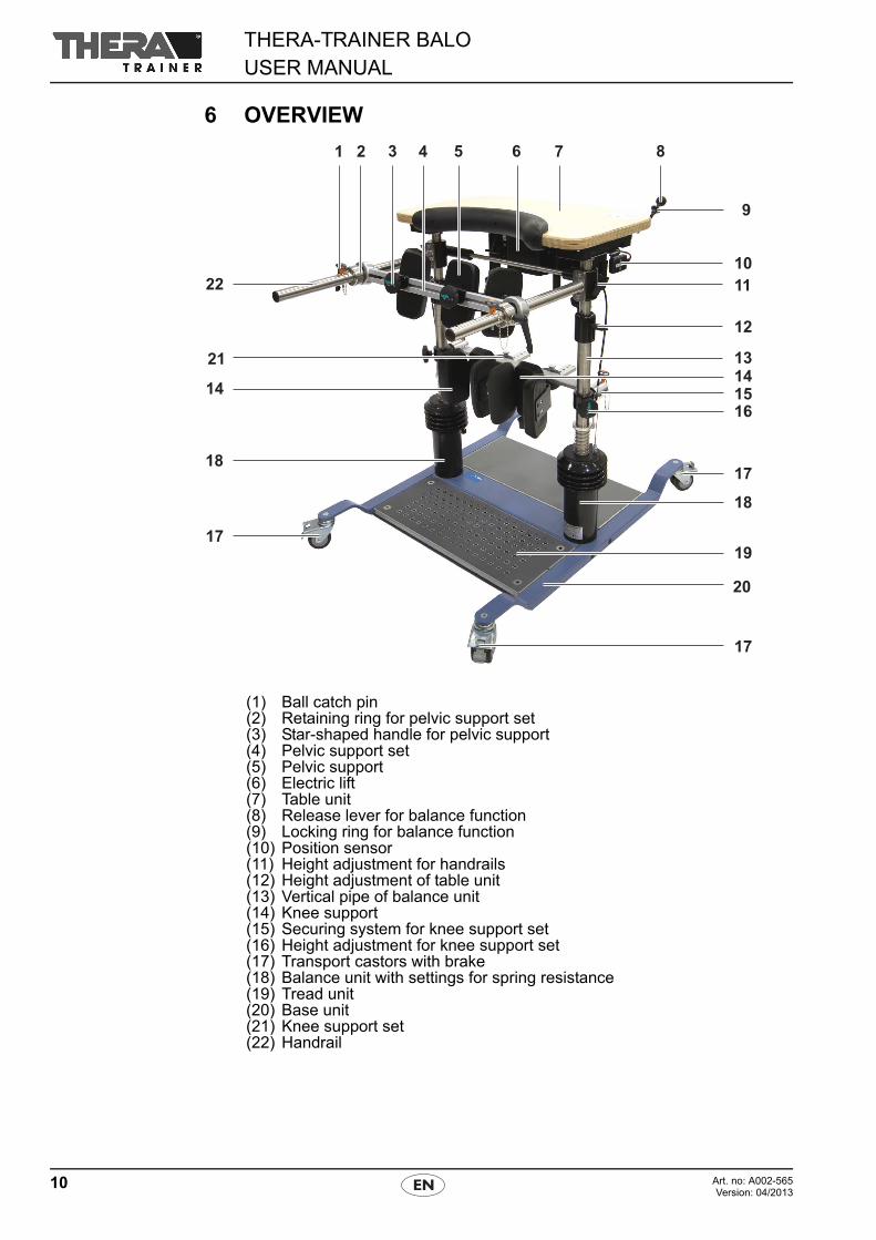
6 OVERVIEW
(1) Ball catch pin(2) Retaining ring for pelvic support set(3) Star-shaped handle for pelvic support(4) Pelvic support set(5) Pelvic support(6) Electric lift(7) Table unit(8) Release lever for balance function(9) Locking ring for balance function(10) Position sensor(11) Height adjustment for handrails(12) Height adjustment of table unit(13) Vertical pipe of balance unit(14) Knee support(15) Securing system for knee support set(16) Height adjustment for knee support set(17) Transport castors with brake(18) Balance unit with settings for spring resistance(19) Tread unit(20) Base unit(21) Knee support set(22) Handrail
11Art. no: A002-565Version: 04/2013
THERA-TRAINER BALOUSER MANUAL
7 START-UP
7.1 Unpacking
Unpack THERA-Trainer balo:
Remove THERA-Trainer balo from packaging. Check THERA-Trainer balo incl. all accessories/options for transport
damage. Check if delivery is complete. Inform supplier or forwarding agent immediately about any damage. Make sure that voltage supply matches voltage of electric lift.
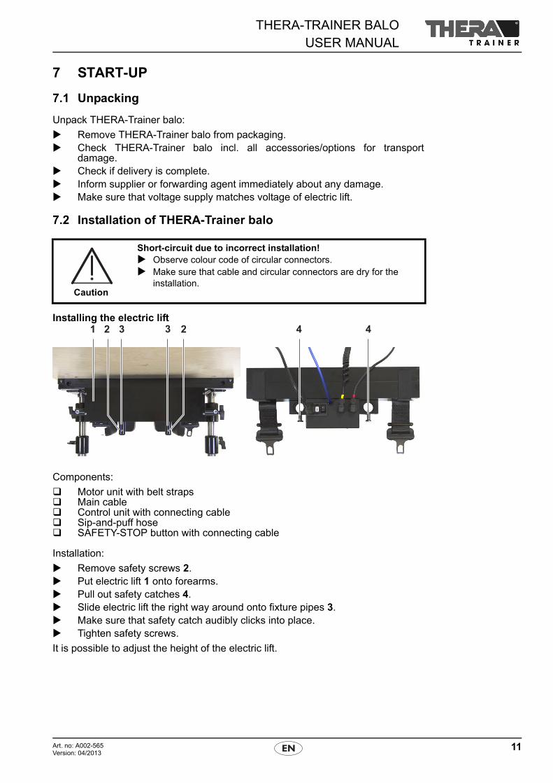
7.2 Installation of THERA-Trainer balo
Installing the electric lift
Components:
Motor unit with belt straps Main cable Control unit with connecting cable Sip-and-puff hose SAFETY-STOP button with connecting cable
Installation:
Remove safety screws 2. Put electric lift 1 onto forearms. Pull out safety catches 4. Slide electric lift the right way around onto fixture pipes 3. Make sure that safety catch audibly clicks into place. Tighten safety screws.
It is possible to adjust the height of the electric lift.
Caution
Short-circuit due to incorrect installation! Observe colour code of circular connectors. Make sure that cable and circular connectors are dry for the
installation.
THERA-TRAINER BALOUSER MANUAL
12 Art. no: A002-565Version: 04/2013
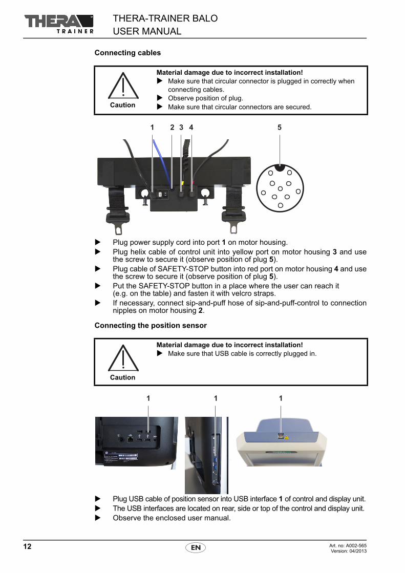
Connecting cables
Plug power supply cord into port 1 on motor housing. Plug helix cable of control unit into yellow port on motor housing 3 and use
the screw to secure it (observe position of plug 5). Plug cable of SAFETY-STOP button into red port on motor housing 4 and use
the screw to secure it (observe position of plug 5). Put the SAFETY-STOP button in a place where the user can reach it
(e.g. on the table) and fasten it with velcro straps. If necessary, connect sip-and-puff hose of sip-and-puff-control to connection
nipples on motor housing 2.
Connecting the position sensor
Plug USB cable of position sensor into USB interface 1 of control and display unit. The USB interfaces are located on rear, side or top of the control and display unit. Observe the enclosed user manual.
Caution
Material damage due to incorrect installation! Make sure that circular connector is plugged in correctly when
connecting cables. Observe position of plug. Make sure that circular connectors are secured.
Caution
Material damage due to incorrect installation! Make sure that USB cable is correctly plugged in.
13Art. no: A002-565Version: 04/2013
THERA-TRAINER BALOUSER MANUAL
7.3 Transport of THERA-Trainer balo
Use exclusively transport castors with brake for moving the THERA-Trainer balo. Before any transport, make sure that
– THERA-Trainer balo is standing on transport castors with brake.– balance function is locked.
8 OPERATION
8.1 Preparation for training
NoteHeight markings on table unit, knee supports and handrails make it easy to changehorizontal settings.Before every training session, adjust settings of THERA-Trainer balo to match theuser's individual needs.
Locking transport castors with brake
Prevent THERA-Trainer balo from moving as follows:
Before every training session, lock all four transport castors with brake. Push down locking lever on transport castors with brake.
Releasing transport castors with brake
To transport THERA-Trainer balo:
Release locking lever on transport castors with brake.
Warning
Risk of injury due to incorrect transport! Do not use THERA-Trainer balo for training in transport con-
dition. Never use THERA-Trainer balo to transport users.
Warning
Risk of injury due to insufficient preparation! Before starting any exercise, make sure that balance unit is
intact and working correctly. Make sure that patient belt with leg straps and bottom enlarged is
intact (e.g. no defective seams). Make sure that patient belt with leg straps and bottom enlarged is
correctly positioned and and safely connected to the buckles. Make sure that pelvic support set is correctly fastened. Disinfect THERA-Trainer balo before every training
(see 10 Cleaning and disinfection).
THERA-TRAINER BALOUSER MANUAL
14 Art. no: A002-565Version: 04/2013
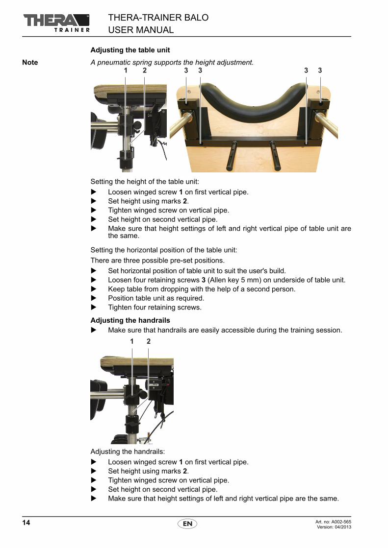
Adjusting the table unit
Note A pneumatic spring supports the height adjustment.
Setting the height of the table unit:
Loosen winged screw 1 on first vertical pipe. Set height using marks 2. Tighten winged screw on vertical pipe. Set height on second vertical pipe. Make sure that height settings of left and right vertical pipe of table unit are
the same.
Setting the horizontal position of the table unit:
There are three possible pre-set positions.
Set horizontal position of table unit to suit the user's build. Loosen four retaining screws 3 (Allen key 5 mm) on underside of table unit. Keep table from dropping with the help of a second person. Position table unit as required. Tighten four retaining screws.
Adjusting the handrails Make sure that handrails are easily accessible during the training session.
Adjusting the handrails:
Loosen winged screw 1 on first vertical pipe. Set height using marks 2. Tighten winged screw on vertical pipe. Set height on second vertical pipe. Make sure that height settings of left and right vertical pipe are the same.
15Art. no: A002-565Version: 04/2013
THERA-TRAINER BALOUSER MANUAL
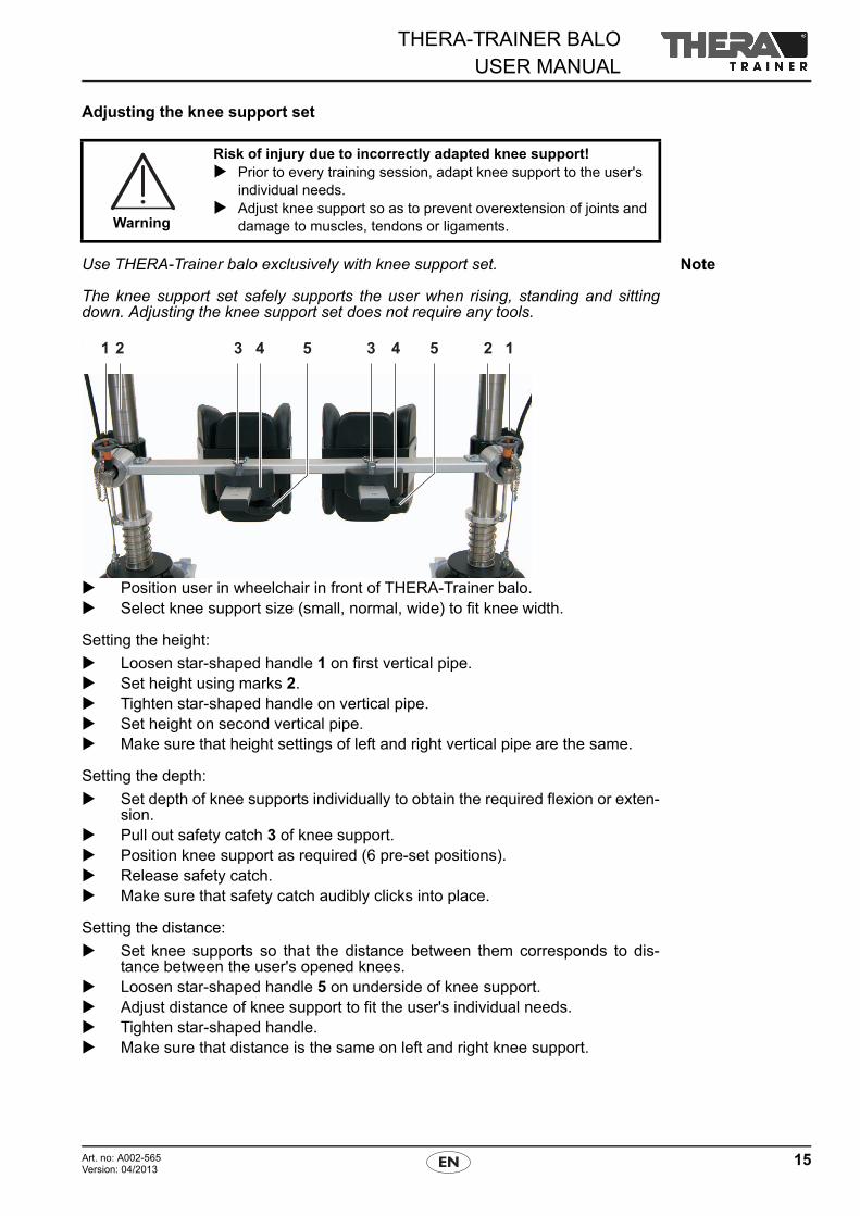
Adjusting the knee support set
NoteUse THERA-Trainer balo exclusively with knee support set.
The knee support set safely supports the user when rising, standing and sittingdown. Adjusting the knee support set does not require any tools.
.
Position user in wheelchair in front of THERA-Trainer balo. Select knee support size (small, normal, wide) to fit knee width.
Setting the height:
Loosen star-shaped handle 1 on first vertical pipe. Set height using marks 2. Tighten star-shaped handle on vertical pipe. Set height on second vertical pipe. Make sure that height settings of left and right vertical pipe are the same.
Setting the depth:
Set depth of knee supports individually to obtain the required flexion or exten-sion.
Pull out safety catch 3 of knee support. Position knee support as required (6 pre-set positions). Release safety catch. Make sure that safety catch audibly clicks into place.
Setting the distance:
Set knee supports so that the distance between them corresponds to dis-tance between the user's opened knees.
Loosen star-shaped handle 5 on underside of knee support. Adjust distance of knee support to fit the user's individual needs. Tighten star-shaped handle. Make sure that distance is the same on left and right knee support.
Warning
Risk of injury due to incorrectly adapted knee support! Prior to every training session, adapt knee support to the user's
individual needs. Adjust knee support so as to prevent overextension of joints and
damage to muscles, tendons or ligaments.
THERA-TRAINER BALOUSER MANUAL
16 Art. no: A002-565Version: 04/2013
Removing a single knee support:
Remove knee support before user is standing in THERA-Trainer balo. Pull out safety catch 3 of knee support. Pull knee support out of securing system 4. Make sure that user is able to maintain upright standing position safely and
without assistance. Never remove both knee supports at the same time.
Lowering the knee supports:
It is possible to lower the knee supports by 60 mm.
Observe extra service instructions.
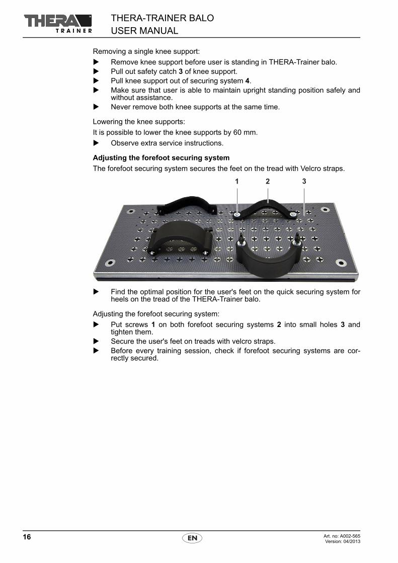
Adjusting the forefoot securing system
The forefoot securing system secures the feet on the tread with Velcro straps.
Find the optimal position for the user's feet on the quick securing system forheels on the tread of the THERA-Trainer balo.
Adjusting the forefoot securing system:
Put screws 1 on both forefoot securing systems 2 into small holes 3 andtighten them.
Secure the user's feet on treads with velcro straps. Before every training session, check if forefoot securing systems are cor-
rectly secured.
17Art. no: A002-565Version: 04/2013
THERA-TRAINER BALOUSER MANUAL
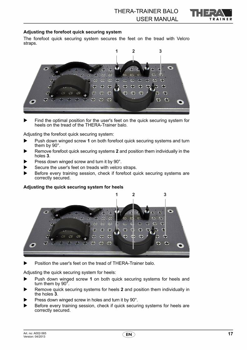
Adjusting the forefoot quick securing system
The forefoot quick securing system secures the feet on the tread with Velcrostraps.
Find the optimal position for the user's feet on the quick securing system forheels on the tread of the THERA-Trainer balo.
Adjusting the forefoot quick securing system:
Push down winged screw 1 on both forefoot quick securing systems and turnthem by 90°.
Remove forefoot quick securing systems 2 and position them individually in theholes 3.
Press down winged screw and turn it by 90°. Secure the user's feet on treads with velcro straps. Before every training session, check if forefoot quick securing systems are
correctly secured.
Adjusting the quick securing system for heels
Position the user's feet on the tread of THERA-Trainer balo.
Adjusting the quick securing system for heels:
Push down winged screw 1 on both quick securing systems for heels andturn them by 90°.
Remove quick securing systems for heels 2 and position them individually inthe holes 3.
Press down winged screw in holes and turn it by 90°. Before every training session, check if quick securing systems for heels are
correctly secured.
THERA-TRAINER BALOUSER MANUAL
18 Art. no: A002-565Version: 04/2013
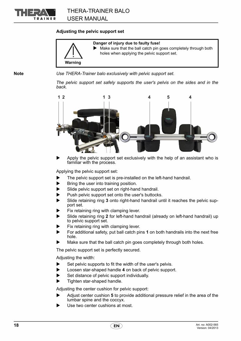
Adjusting the pelvic support set
Note Use THERA-Trainer balo exclusively with pelvic support set.
The pelvic support set safely supports the user's pelvis on the sides and in theback.
Apply the pelvic support set exclusively with the help of an assistant who isfamiliar with the process.
Applying the pelvic support set:
The pelvic support set is pre-installed on the left-hand handrail. Bring the user into training position. Slide pelvic support set on right-hand handrail. Push pelvic support set onto the user's buttocks. Slide retaining ring 3 onto right-hand handrail until it reaches the pelvic sup-
port set. Fix retaining ring with clamping lever. Slide retaining ring 2 for left-hand handrail (already on left-hand handrail) up
to pelvic support set. Fix retaining ring with clamping lever. For additional safety, put ball catch pins 1 on both handrails into the next free
hole. Make sure that the ball catch pin goes completely through both holes.
The pelvic support set is perfectly secured.
Adjusting the width:
Set pelvic supports to fit the width of the user's pelvis. Loosen star-shaped handle 4 on back of pelvic support. Set distance of pelvic support individually. Tighten star-shaped handle.
Adjusting the center cushion for pelvic support:
Adjust center cushion 5 to provide additional pressure relief in the area of thelumbar spine and the coccyx.
Use two center cushions at most.
Warning
Danger of injury due to faulty fuse! Make sure that the ball catch pin goes completely through both
holes when applying the pelvic support set.
19Art. no: A002-565Version: 04/2013
THERA-TRAINER BALOUSER MANUAL
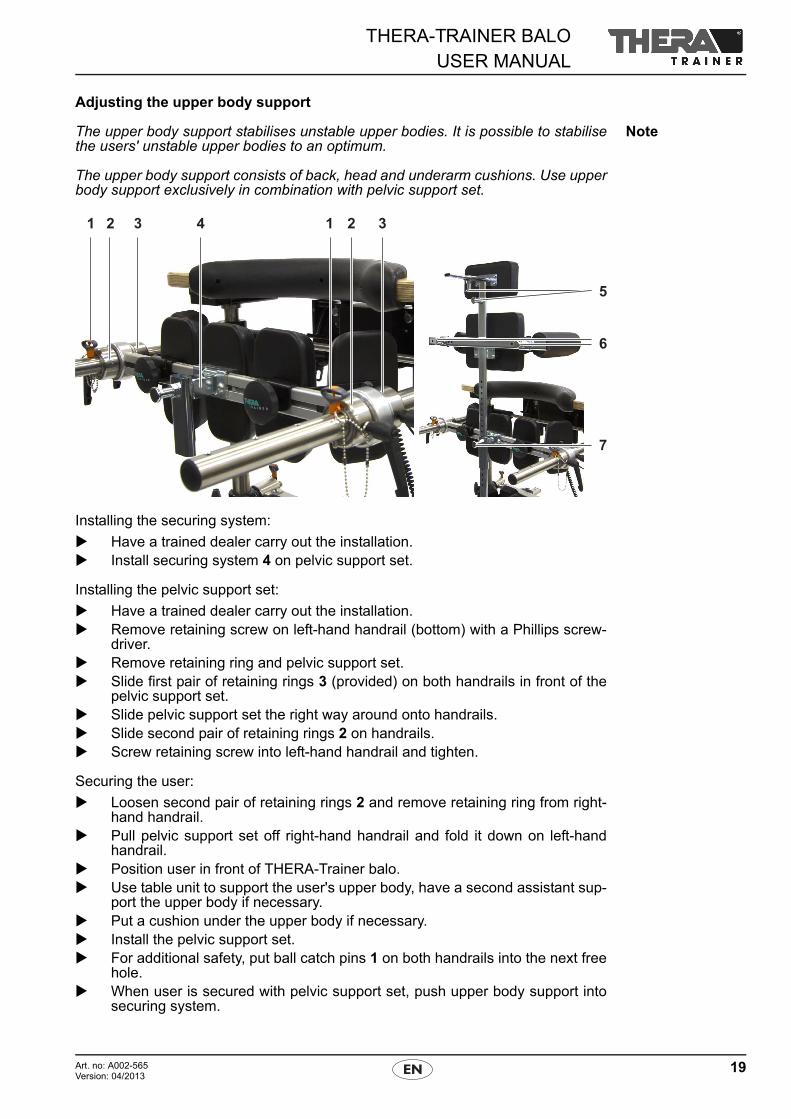
Adjusting the upper body support
NoteThe upper body support stabilises unstable upper bodies. It is possible to stabilisethe users' unstable upper bodies to an optimum.
The upper body support consists of back, head and underarm cushions. Use upperbody support exclusively in combination with pelvic support set.
Installing the securing system:
Have a trained dealer carry out the installation. Install securing system 4 on pelvic support set.
Installing the pelvic support set:
Have a trained dealer carry out the installation. Remove retaining screw on left-hand handrail (bottom) with a Phillips screw-
driver. Remove retaining ring and pelvic support set. Slide first pair of retaining rings 3 (provided) on both handrails in front of the
pelvic support set. Slide pelvic support set the right way around onto handrails. Slide second pair of retaining rings 2 on handrails. Screw retaining screw into left-hand handrail and tighten.
Securing the user:
Loosen second pair of retaining rings 2 and remove retaining ring from right-hand handrail.
Pull pelvic support set off right-hand handrail and fold it down on left-handhandrail.
Position user in front of THERA-Trainer balo. Use table unit to support the user's upper body, have a second assistant sup-
port the upper body if necessary. Put a cushion under the upper body if necessary. Install the pelvic support set. For additional safety, put ball catch pins 1 on both handrails into the next free
hole. When user is secured with pelvic support set, push upper body support into
securing system.
THERA-TRAINER BALOUSER MANUAL
20 Art. no: A002-565Version: 04/2013
Pushing the upper body support into the securing system:
Pull out safety catch 7 on securing system. Push upper body support into securing system. Set height as required. Release safety catch. Make sure that safety catch audibly clicks into place.
Applying the upper body support:
Straighten the user into an upright position. Make sure that pelvic support set and the four retaining rings fastened tightly
and without slack. Secure user with upper body support. Adjust cushions of upper body support with safety catches 5/6 to fit the user's
needs. Adapt chest belt to the user's chest circumference. Secure user completely with upper body support.
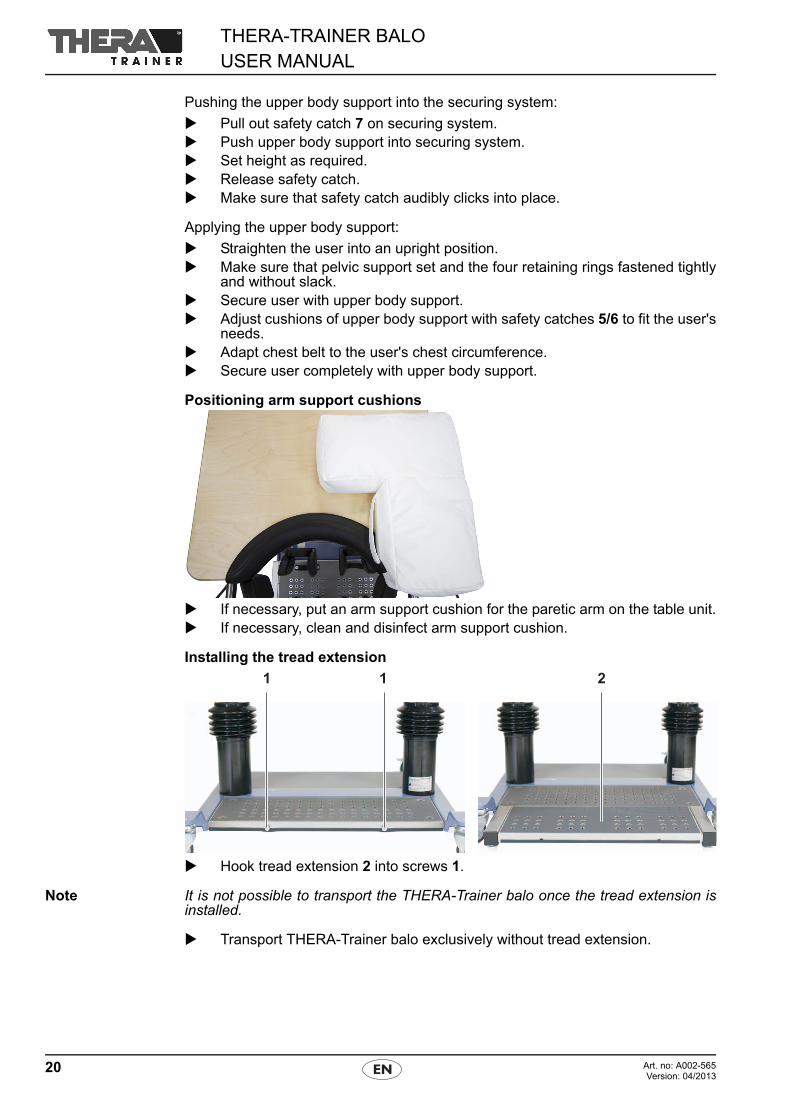
Positioning arm support cushions
If necessary, put an arm support cushion for the paretic arm on the table unit. If necessary, clean and disinfect arm support cushion.
Installing the tread extension
Hook tread extension 2 into screws 1.
Note It is not possible to transport the THERA-Trainer balo once the tread extension isinstalled.
Transport THERA-Trainer balo exclusively without tread extension.
21Art. no: A002-565Version: 04/2013
THERA-TRAINER BALOUSER MANUAL
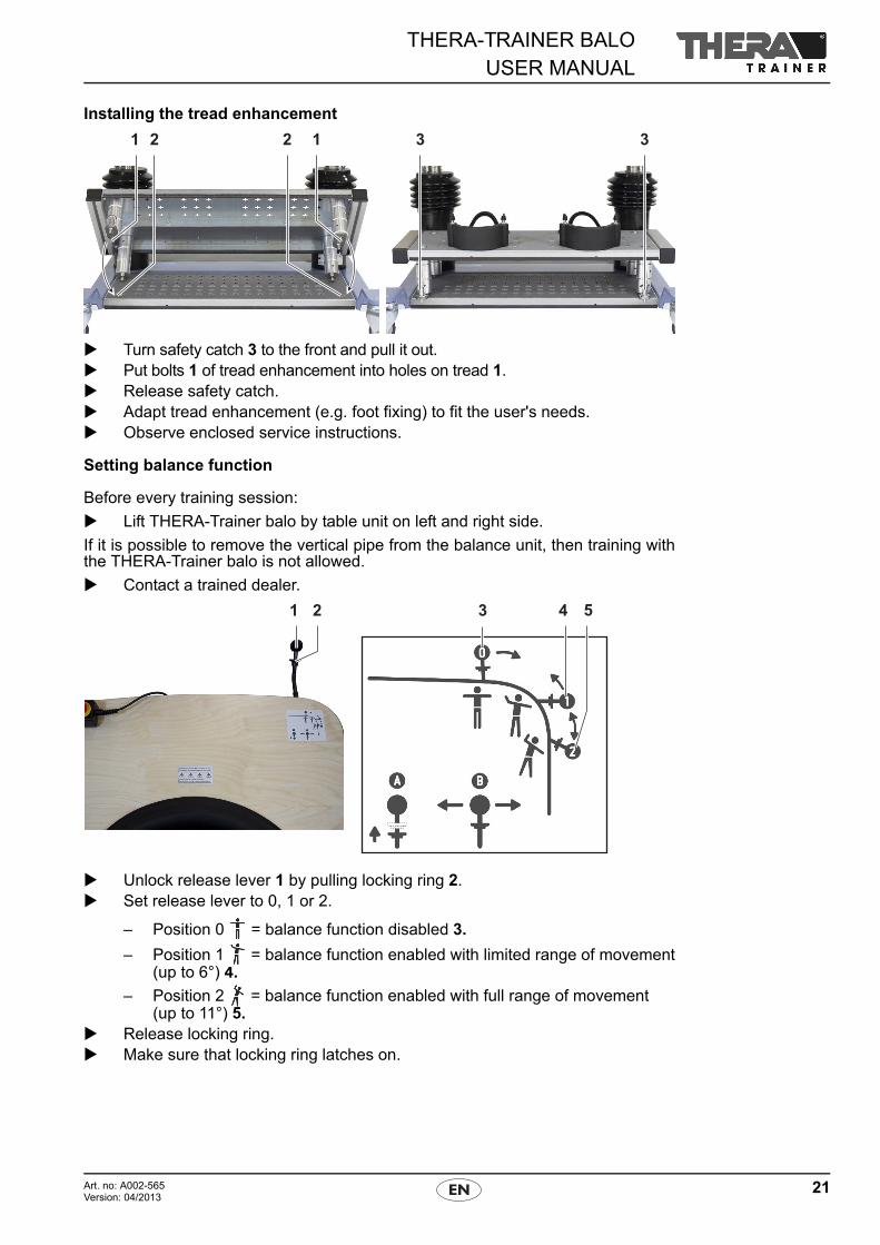
Installing the tread enhancement
Turn safety catch 3 to the front and pull it out. Put bolts 1 of tread enhancement into holes on tread 1. Release safety catch. Adapt tread enhancement (e.g. foot fixing) to fit the user's needs. Observe enclosed service instructions.
Setting balance function
Before every training session:
Lift THERA-Trainer balo by table unit on left and right side.
If it is possible to remove the vertical pipe from the balance unit, then training withthe THERA-Trainer balo is not allowed.
Contact a trained dealer.
Unlock release lever 1 by pulling locking ring 2. Set release lever to 0, 1 or 2.
– Position 0 = balance function disabled 3.
– Position 1 = balance function enabled with limited range of movement(up to 6°) 4.
– Position 2 = balance function enabled with full range of movement (up to 11°) 5.
Release locking ring. Make sure that locking ring latches on.
THERA-TRAINER BALOUSER MANUAL
22 Art. no: A002-565Version: 04/2013
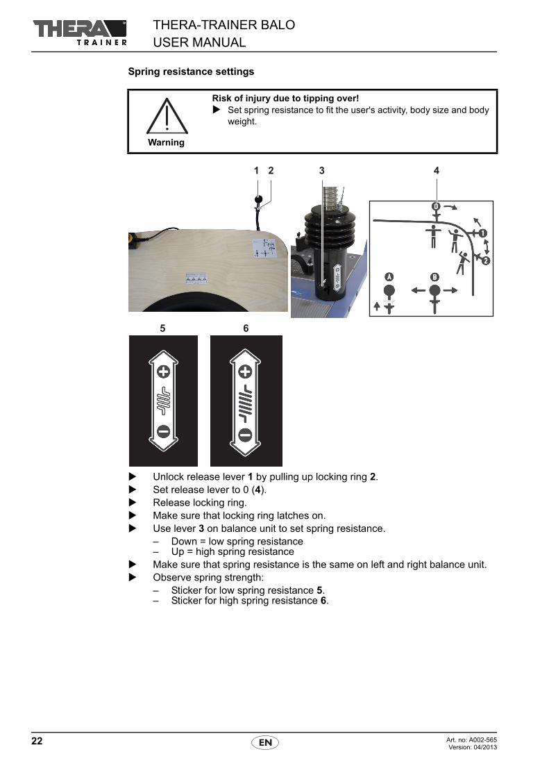
Spring resistance settings
Unlock release lever 1 by pulling up locking ring 2. Set release lever to 0 (4). Release locking ring. Make sure that locking ring latches on. Use lever 3 on balance unit to set spring resistance.
– Down = low spring resistance– Up = high spring resistance
Make sure that spring resistance is the same on left and right balance unit. Observe spring strength:
– Sticker for low spring resistance 5.– Sticker for high spring resistance 6.
Warning
Risk of injury due to tipping over! Set spring resistance to fit the user's activity, body size and body
weight.
23Art. no: A002-565Version: 04/2013
THERA-TRAINER BALOUSER MANUAL
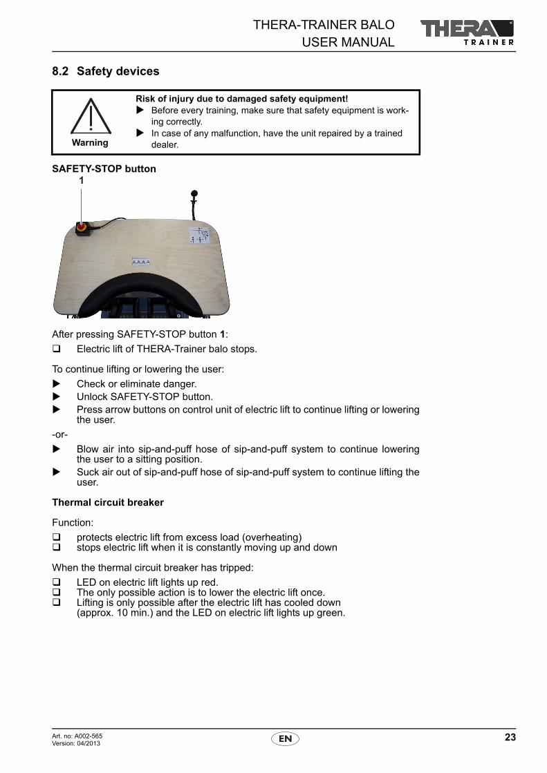
8.2 Safety devices
SAFETY-STOP button
After pressing SAFETY-STOP button 1:
Electric lift of THERA-Trainer balo stops.
To continue lifting or lowering the user:
Check or eliminate danger. Unlock SAFETY-STOP button. Press arrow buttons on control unit of electric lift to continue lifting or lowering
the user.
-or-
Blow air into sip-and-puff hose of sip-and-puff system to continue loweringthe user to a sitting position.
Suck air out of sip-and-puff hose of sip-and-puff system to continue lifting theuser.
Thermal circuit breaker
Function:
protects electric lift from excess load (overheating) stops electric lift when it is constantly moving up and down
When the thermal circuit breaker has tripped:
LED on electric lift lights up red. The only possible action is to lower the electric lift once. Lifting is only possible after the electric lift has cooled down
(approx. 10 min.) and the LED on electric lift lights up green.
Warning
Risk of injury due to damaged safety equipment! Before every training, make sure that safety equipment is work-
ing correctly. In case of any malfunction, have the unit repaired by a trained
dealer.
THERA-TRAINER BALOUSER MANUAL
24 Art. no: A002-565Version: 04/2013
9 CONTROL
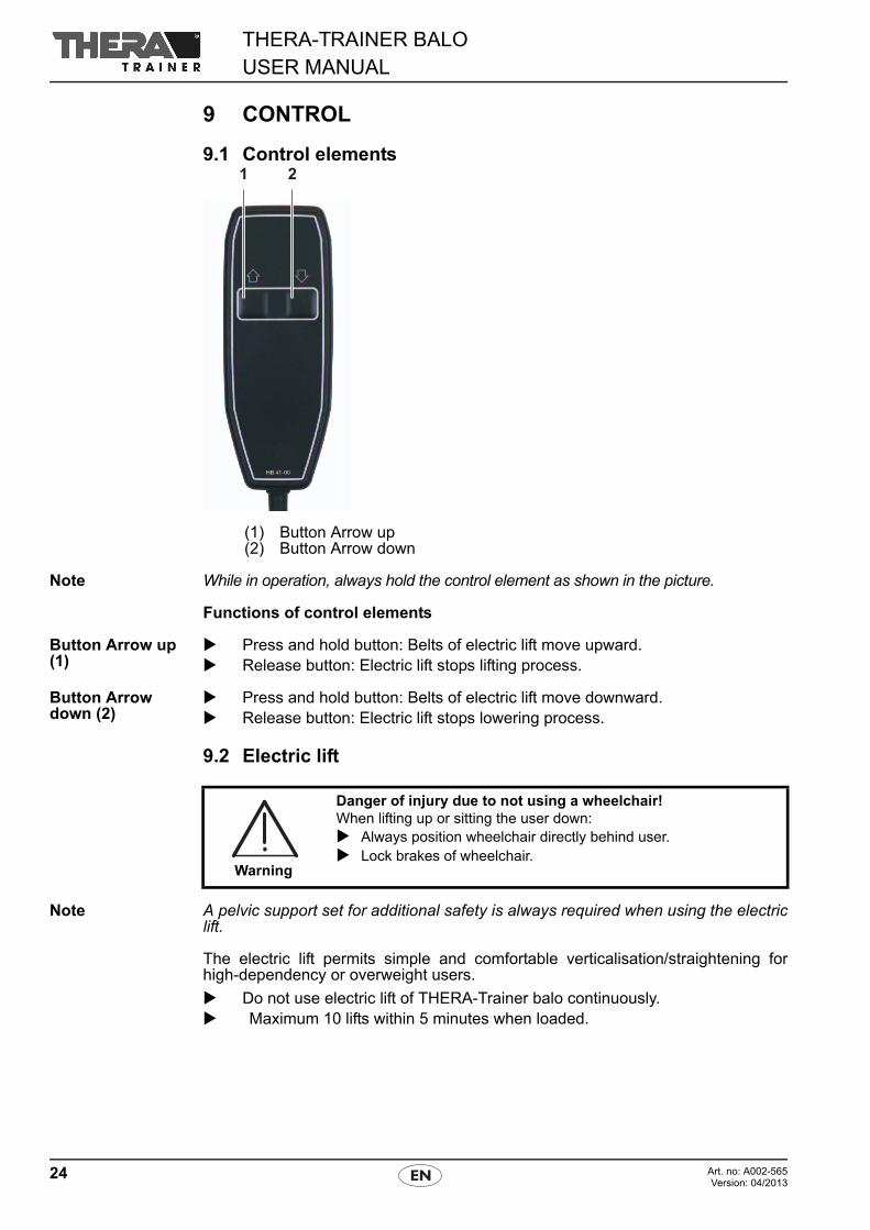
9.1 Control elements
(1) Button Arrow up(2) Button Arrow down
Note While in operation, always hold the control element as shown in the picture.
Functions of control elements
Button Arrow up (1)
Press and hold button: Belts of electric lift move upward. Release button: Electric lift stops lifting process.
Button Arrow down (2)
Press and hold button: Belts of electric lift move downward. Release button: Electric lift stops lowering process.
9.2 Electric lift
Note A pelvic support set for additional safety is always required when using the electriclift.
The electric lift permits simple and comfortable verticalisation/straightening forhigh-dependency or overweight users.
Do not use electric lift of THERA-Trainer balo continuously. Maximum 10 lifts within 5 minutes when loaded.
Warning
Danger of injury due to not using a wheelchair!When lifting up or sitting the user down: Always position wheelchair directly behind user. Lock brakes of wheelchair.
25Art. no: A002-565Version: 04/2013
THERA-TRAINER BALOUSER MANUAL
Starting up the electric lift
Plug power plug into socket outlet. Switch on electric lift with ON-/OFF-button. Make sure that SAFETY-STOP button is unlocked.
Green LED is on.
Check if SAFETY-STOP button is functional. Unlock SAFETY-STOP button.
THERA-Trainer balo is ready for use.
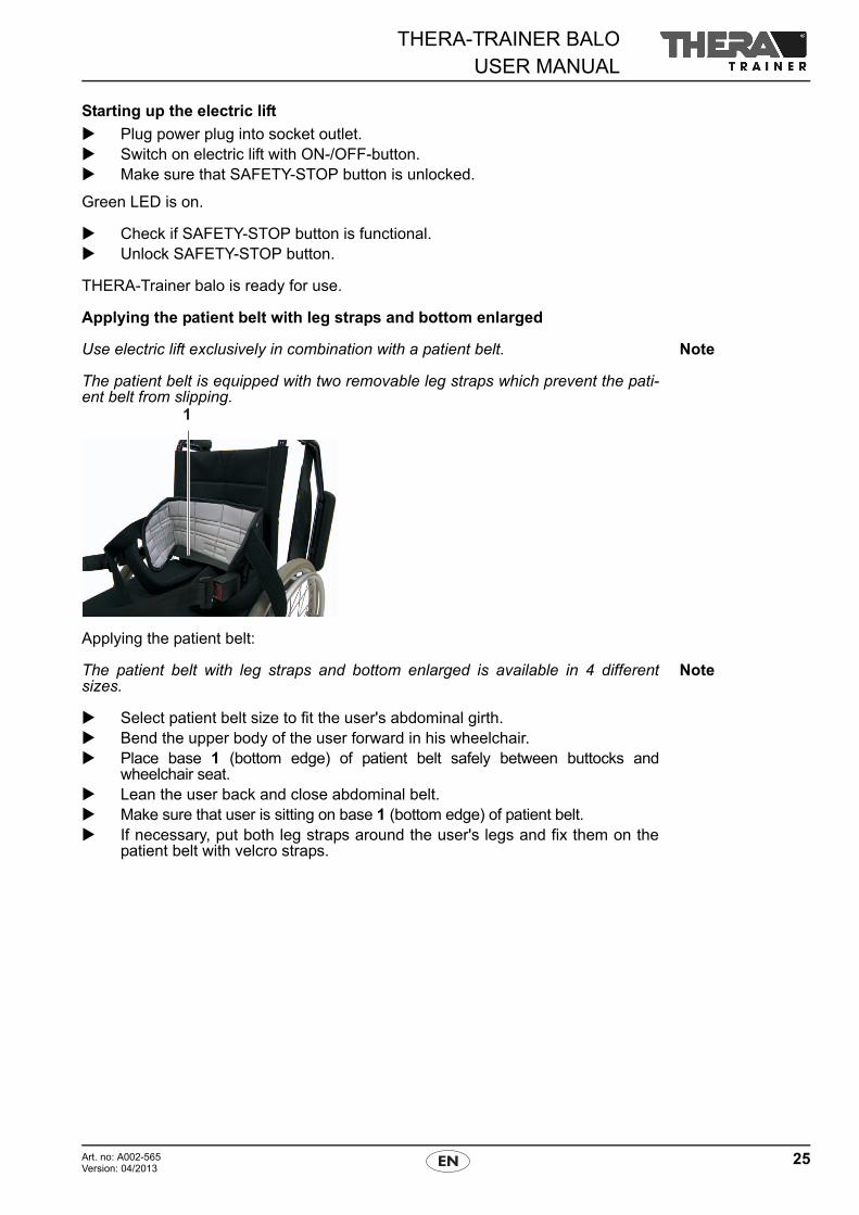
Applying the patient belt with leg straps and bottom enlarged
NoteUse electric lift exclusively in combination with a patient belt.
The patient belt is equipped with two removable leg straps which prevent the pati-ent belt from slipping.
Applying the patient belt:
NoteThe patient belt with leg straps and bottom enlarged is available in 4 differentsizes.
Select patient belt size to fit the user's abdominal girth. Bend the upper body of the user forward in his wheelchair. Place base 1 (bottom edge) of patient belt safely between buttocks and
wheelchair seat. Lean the user back and close abdominal belt. Make sure that user is sitting on base 1 (bottom edge) of patient belt. If necessary, put both leg straps around the user's legs and fix them on the
patient belt with velcro straps.
THERA-TRAINER BALOUSER MANUAL
26 Art. no: A002-565Version: 04/2013
Controlling the electric lift via control unit
To lift the user:
Press button Arrow down on control unit.
Belts move down.
Pull down right and left belt. Close patient belt by putting buckle tongues into buckles. Make sure that buckle tongues audibly click into place. Make sure that base of patient belt is under the user's buttocks. Press button Arrow up on control unit.
The electric lift slowly lifts the user.
To lower the user:
Press button Arrow down on control unit.
The electric lift slowly lowers the user.
Open patient belt by pulling buckle tongues out of belt buckles. Press button Arrow up on control unit.
Belts move up.
Remove patient belt from user.
Controlling the electric lift via sip-and-puff control Plug provided sip-and-puff hose into electric lift.
To lift the user:
Blow air into sip-and-puff hose.
Belts move down.
Pull down right and left belt. Close patient belt by putting buckle tongues into buckles. Make sure that buckle tongues audibly click into place. Make sure that base (bottom edge) of patient belt is under the user's but-
tocks. Suck air out of sip-and-puff hose.
The electric lift slowly lifts the user.
To lower the user:
Blow air into sip-and-puff hose.
The electric lift slowly lowers the user.
Open patient belt by pulling buckle tongues out of belt buckles. Suck air out of sip-and-puff hose.
Belts move up.
Remove patient belt from user.
27Art. no: A002-565Version: 04/2013
THERA-TRAINER BALOUSER MANUAL
9.3 Lifting and lowering without electric lift
NoteIf necessary, lift or lower the user without the electric lift with the help of an assis-tant who is trained for the process.
To lift the user:
Set height (see 8.1 Preparation for training)– of knee supports– of table unit– of handrails
Before starting the training session, make sure that transport castors withbrake are locked.
Move user directly behind THERA-Trainer balo in a wheelchair. Secure wheelchair to prevent it from moving. Put the user's feet on tread of THERA-Trainer balo and secure them
(see 8.1 Preparation for training). Position knees in knee supports. Lift the user and stand him into the training position. Apply pelvic support and secure the user (see 8.1 Preparation for training).
To lower the user:
Move wheelchair directly behind THERA-Trainer balo. Remove pelvic support set from user. Seat user in wheelchair. Remove the user's feet from the tread of THERA-Trainer balo.
Warning
Danger of injury due to faulty fuse! Make sure that the ball catch pin goes completely through both
holes when applying the pelvic support set.
Warning
Danger of injury due to not using a wheelchair!When lifting up or sitting the user down: Always position wheelchair directly behind user. Lock brakes of wheelchair.
THERA-TRAINER BALOUSER MANUAL
28 Art. no: A002-565Version: 04/2013
9.4 Starting up the control and display unit
The control and display unit supports goal-oriented training with biofeedback illus-trations.
Note Use control and display unit with 10.4’’ or 23’’ colour screen exclusively with soft-ware package Balancing individual therapy, position sensor and holder.
Switch on control and display unit. Operate control and display unit via touch soft keys. Observe the enclosed user manual.
Adjusting the mobile holder
Note Mobile holder is suitable for control and display unit with 23” colour screen.
Set mobile holder individually to– correct height.– correct tilt.– correct distance.
Before starting the training session, make sure that transport castors withbrake are locked.
Observe the enclosed user manual.
Adjusting the table holder
Note Table holder is suitable for control and display unit with 10.4” colour screen.
Set table holder individually to correct tilt. Before every training session, make sure that metal support foot is in optimal
training position. Observe the enclosed user manual.
29Art. no: A002-565Version: 04/2013
THERA-TRAINER BALOUSER MANUAL
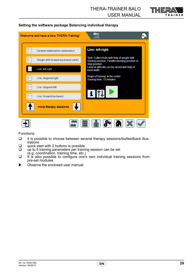
Setting the software package Balancing individual therapy
Functions:
it is possible to choose between several therapy sessions/biofeedback illus-trations
quick start with 2 buttons is possible up to 5 training parameters per training session can be set
(e.g. coordination, training time, etc.) It is also possible to configure one's own individual training sessions from
pre-set modules. Observe the enclosed user manual.
THERA-TRAINER BALOUSER MANUAL
30 Art. no: A002-565Version: 04/2013
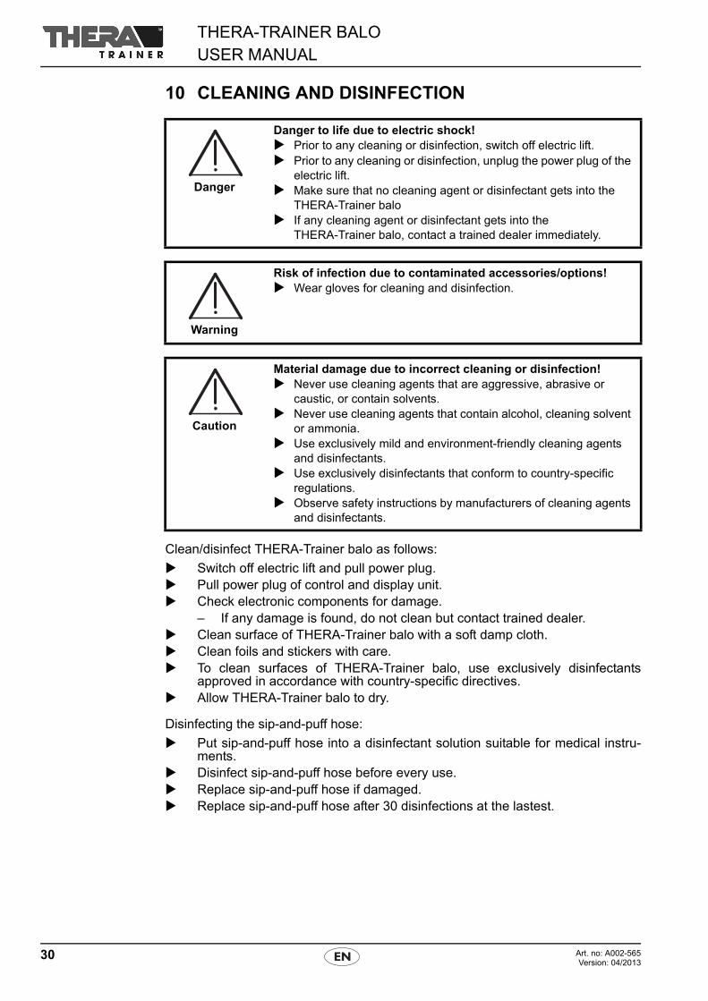
10 CLEANING AND DISINFECTION
Clean/disinfect THERA-Trainer balo as follows:
Switch off electric lift and pull power plug. Pull power plug of control and display unit. Check electronic components for damage.
– If any damage is found, do not clean but contact trained dealer. Clean surface of THERA-Trainer balo with a soft damp cloth. Clean foils and stickers with care. To clean surfaces of THERA-Trainer balo, use exclusively disinfectants
approved in accordance with country-specific directives. Allow THERA-Trainer balo to dry.
Disinfecting the sip-and-puff hose:
Put sip-and-puff hose into a disinfectant solution suitable for medical instru-ments.
Disinfect sip-and-puff hose before every use. Replace sip-and-puff hose if damaged. Replace sip-and-puff hose after 30 disinfections at the lastest.
Danger
Danger to life due to electric shock! Prior to any cleaning or disinfection, switch off electric lift. Prior to any cleaning or disinfection, unplug the power plug of the
electric lift. Make sure that no cleaning agent or disinfectant gets into the
THERA-Trainer balo If any cleaning agent or disinfectant gets into the
THERA-Trainer balo, contact a trained dealer immediately.
Warning
Risk of infection due to contaminated accessories/options! Wear gloves for cleaning and disinfection.
Caution
Material damage due to incorrect cleaning or disinfection! Never use cleaning agents that are aggressive, abrasive or
caustic, or contain solvents. Never use cleaning agents that contain alcohol, cleaning solvent
or ammonia. Use exclusively mild and environment-friendly cleaning agents
and disinfectants. Use exclusively disinfectants that conform to country-specific
regulations. Observe safety instructions by manufacturers of cleaning agents
and disinfectants.
31Art. no: A002-565Version: 04/2013
THERA-TRAINER BALOUSER MANUAL
11 MAINTENANCE AND REPAIR
11.1 Replacing the balance unit
NoteAccording to the manufacturer's specifications, the balance unit of the THERA-Trainer balo must be replaced after five years.
11.2 Replacing the patient belt with leg straps and bottom enlarged
NoteAccording to the manufacturer's specifications, the patient belt with leg straps andbottom enlarged on the THERA-Trainer balo must be replaced after 5 years.
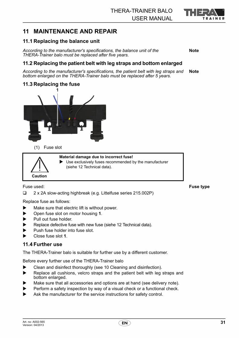
11.3 Replacing the fuse
(1) Fuse slot
Fuse typeFuse used:
2 x 2A slow-acting highbreak (e.g. Littelfuse series 215.002P)
Replace fuse as follows:
Make sure that electric lift is without power. Open fuse slot on motor housing 1. Pull out fuse holder. Replace defective fuse with new fuse (siehe 12 Technical data). Push fuse holder into fuse slot. Close fuse slot 1.
11.4 Further use
The THERA-Trainer balo is suitable for further use by a different customer.
Before every further use of the THERA-Trainer balo
Clean and disinfect thoroughly (see 10 Cleaning and disinfection). Replace all cushions, velcro straps and the patient belt with leg straps and
bottom enlarged. Make sure that all accessories and options are at hand (see delivery note). Perform a safety inspection by way of a visual check or a functional check. Ask the manufacturer for the service instructions for safety control.
Caution
Material damage due to incorrect fuse! Use exclusively fuses recommended by the manufacturer
(siehe 12 Technical data).
THERA-TRAINER BALOUSER MANUAL
32 Art. no: A002-565Version: 04/2013
12 TECHNICAL DATA
13 STANDARDS AND LAWSThe THERA-Trainer balo conforms to the following standards:
MDD 93/42 EEC Machinery directive 2006/42 EC DIN EN 60601-1 DIN EN 60601-2 DIN EN 12182 DIN EN ISO 13485
14 DISPOSAL
To dispose of the THERA-Trainer balo:
Observe country-specific regulations and specifications. Dispose of metal parts as scrap metal. Dispose of plastic parts as prescribed, depending on the type of material. Dispose of electric and electronic components as electronic scrap.
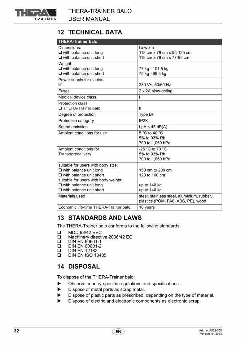
THERA-Trainer balo
Dimensions: with balance unit long with balance unit short
l x w x h118 cm x 78 cm x 95-125 cm118 cm x 78 cm x 77-98 cm
Weight: with balance unit long with balance unit short
77 kg - 101.5 kg75 kg - 99.5 kg
Power supply for electric lift 230 V~, 50/60 Hz
Fuses 2 x 2A slow-acting
Medical device class I
Protection class: THERA-Trainer balo II
Degree of protection Type BF
Protection category IP2X
Sound emission LpA < 45 dB(A)
Ambient conditions for use 5 °C to 40 °C5% to 93% Rh700 to 1,060 hPa
Ambient conditions forTransport/delivery
-25 °C to 70 °C 5% to 93% Rh700 to 1,060 hPa
suitable for users with body size: with balance unit long with balance unit shortsuitable for users with body weight: with balance unit long with balance unit short
150 cm to 200 cm120 to 160 cm
up to 140 kgup to 140 kg
Materials used steel, stainless steel, aluminium, rubber, plastics (POM, PA6, ABS, PE), wood
Economic life-time THERA-Trainer balo: 10 years
33Art. no: A002-565Version: 04/2013
THERA-TRAINER BALOUSER MANUAL
15 NOTES ON ELECTROMAGNETIC COMPATIBILITY
15.1Lines, line lengths and accessories
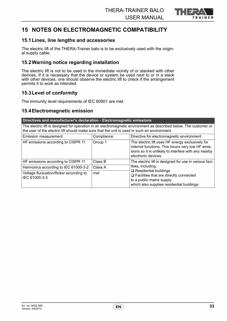
The electric lift of the THERA-Trainer balo is to be exclusively used with the origin-al supply cable.
15.2Warning notice regarding installation
The electric lift is not to be used in the immediate vicinity of or stacked with otherdevices. If it is necessary that the device or system be used next to or in a stackwith other devices, one should observe the electric lift to check if the arrangementpermits it to work as intended.
15.3Level of conformity
The immunity level requirements of IEC 60601 are met.
15.4Electromagnetic emission
Directives and manufacturer's declaration - Electromagnetic emissions
The electric lift is designed for operation in an electromagnetic environment as described below. The customer or the user of the electric lift should make sure that the unit is used in such an environment.
Emission measurement Compliance Directive for electromagnetic environment
HF emissions according to CISPR 11 Group 1 The electric lift uses HF energy exclusively for internal functions. This incurs very low HF emis-sions so it is unlikely to interfere with any nearby electronic devices.
HF emissions according to CISPR 11 Class B The electric lift is designed for use in various faci-lities, including: Residential buildings Facilities that are directly connectedto a public mains supplywhich also supplies residential buildings.
Harmonics according to IEC 61000-3-2 Class A
Voltage fluctuation/flicker according to IEC 61000-3-3
met
THERA-TRAINER BALOUSER MANUAL
34 Art. no: A002-565Version: 04/2013
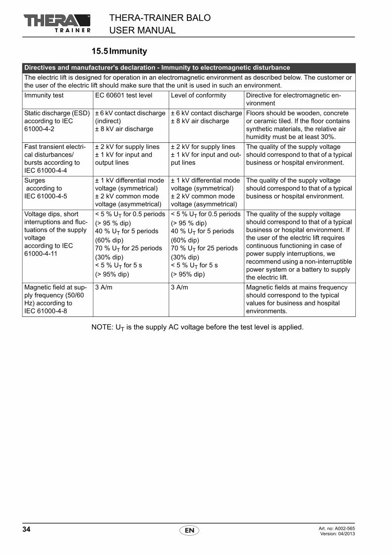
15.5 Immunity
NOTE: UT is the supply AC voltage before the test level is applied.
Directives and manufacturer's declaration - Immunity to electromagnetic disturbance
The electric lift is designed for operation in an electromagnetic environment as described below. The customer or the user of the electric lift should make sure that the unit is used in such an environment.
Immunity test EC 60601 test level Level of conformity Directive for electromagnetic en-vironment
Static discharge (ESD) according to IEC 61000-4-2
± 6 kV contact discharge (indirect)± 8 kV air discharge
± 6 kV contact discharge± 8 kV air discharge
Floors should be wooden, concrete or ceramic tiled. If the floor contains synthetic materials, the relative air humidity must be at least 30%.
Fast transient electri-cal disturbances/bursts according toIEC 61000-4-4
± 2 kV for supply lines± 1 kV for input and output lines
± 2 kV for supply lines± 1 kV for input and out-put lines
The quality of the supply voltage should correspond to that of a typical business or hospital environment.
Surges according toIEC 61000-4-5
± 1 kV differential mode voltage (symmetrical)± 2 kV common mode voltage (asymmetrical)
± 1 kV differential mode voltage (symmetrical)± 2 kV common mode voltage (asymmetrical)
The quality of the supply voltage should correspond to that of a typical business or hospital environment.
Voltage dips, short interruptions and fluc-tuations of the supply voltageaccording to IEC 61000-4-11
< 5 % UT for 0.5 periods (> 95 % dip)40 % UT for 5 periods(60% dip)70 % UT for 25 periods(30% dip)< 5 % UT for 5 s(> 95% dip)
< 5 % UT for 0.5 periods (> 95 % dip)40 % UT for 5 periods(60% dip)70 % UT for 25 periods(30% dip)< 5 % UT for 5 s(> 95% dip)
The quality of the supply voltage should correspond to that of a typical business or hospital environment. If the user of the electric lift requires continuous functioning in case of power supply interruptions, we recommend using a non-interruptible power system or a battery to supply the electric lift.
Magnetic field at sup-ply frequency (50/60 Hz) according to IEC 61000-4-8
3 A/m 3 A/m Magnetic fields at mains frequency should correspond to the typical values for business and hospital environments.
35Art. no: A002-565Version: 04/2013
THERA-TRAINER BALOUSER MANUAL
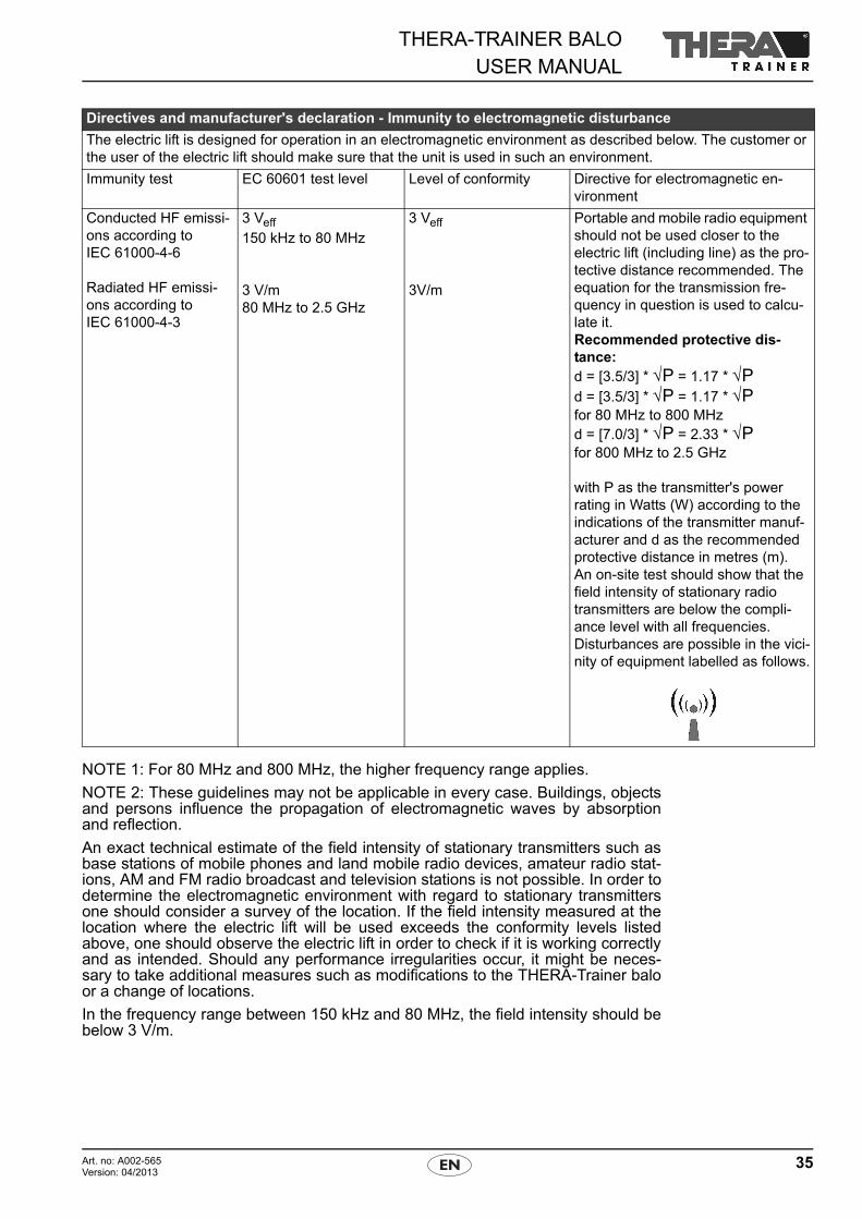
NOTE 1: For 80 MHz and 800 MHz, the higher frequency range applies.
NOTE 2: These guidelines may not be applicable in every case. Buildings, objectsand persons influence the propagation of electromagnetic waves by absorptionand reflection.
An exact technical estimate of the field intensity of stationary transmitters such asbase stations of mobile phones and land mobile radio devices, amateur radio stat-ions, AM and FM radio broadcast and television stations is not possible. In order todetermine the electromagnetic environment with regard to stationary transmittersone should consider a survey of the location. If the field intensity measured at thelocation where the electric lift will be used exceeds the conformity levels listedabove, one should observe the electric lift in order to check if it is working correctlyand as intended. Should any performance irregularities occur, it might be neces-sary to take additional measures such as modifications to the THERA-Trainer baloor a change of locations.
In the frequency range between 150 kHz and 80 MHz, the field intensity should bebelow 3 V/m.
Directives and manufacturer's declaration - Immunity to electromagnetic disturbance
The electric lift is designed for operation in an electromagnetic environment as described below. The customer or the user of the electric lift should make sure that the unit is used in such an environment.
Immunity test EC 60601 test level Level of conformity Directive for electromagnetic en-vironment
Conducted HF emissi-ons according to IEC 61000-4-6
Radiated HF emissi-ons according to IEC 61000-4-3
3 Veff
150 kHz to 80 MHz
3 V/m80 MHz to 2.5 GHz
3 Veff
3V/m
Portable and mobile radio equipment should not be used closer to the electric lift (including line) as the pro-tective distance recommended. The equation for the transmission fre-quency in question is used to calcu-late it.Recommended protective dis-tance:d = [3.5/3] * √P = 1.17 * √Pd = [3.5/3] * √P = 1.17 * √P for 80 MHz to 800 MHzd = [7.0/3] * √P = 2.33 * √Pfor 800 MHz to 2.5 GHz
with P as the transmitter's power rating in Watts (W) according to the indications of the transmitter manuf-acturer and d as the recommended protective distance in metres (m).An on-site test should show that the field intensity of stationary radio transmitters are below the compli-ance level with all frequencies.Disturbances are possible in the vici-nity of equipment labelled as follows.
THERA-TRAINER BALOUSER MANUAL
36 Art. no: A002-565Version: 04/2013
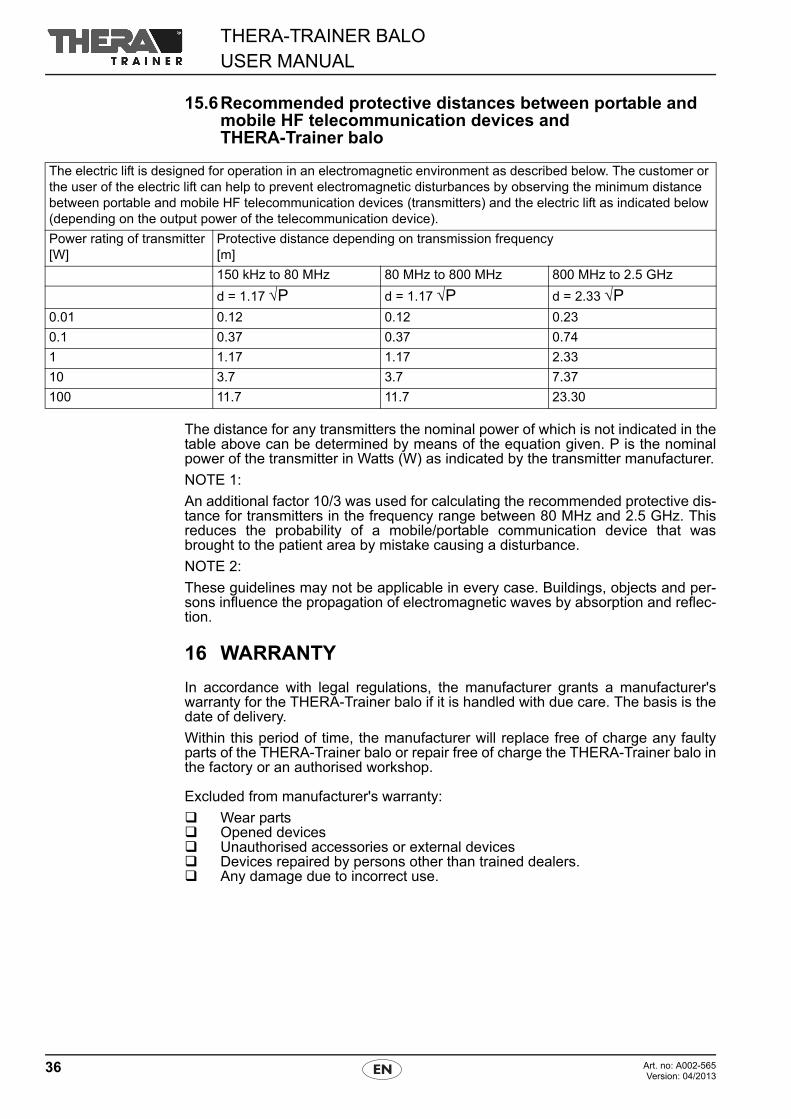
15.6Recommended protective distances between portable and mobile HF telecommunication devices and THERA-Trainer balo
The distance for any transmitters the nominal power of which is not indicated in thetable above can be determined by means of the equation given. P is the nominalpower of the transmitter in Watts (W) as indicated by the transmitter manufacturer.
NOTE 1:
An additional factor 10/3 was used for calculating the recommended protective dis-tance for transmitters in the frequency range between 80 MHz and 2.5 GHz. Thisreduces the probability of a mobile/portable communication device that wasbrought to the patient area by mistake causing a disturbance.
NOTE 2:
These guidelines may not be applicable in every case. Buildings, objects and per-sons influence the propagation of electromagnetic waves by absorption and reflec-tion.
16 WARRANTY
In accordance with legal regulations, the manufacturer grants a manufacturer'swarranty for the THERA-Trainer balo if it is handled with due care. The basis is thedate of delivery.
Within this period of time, the manufacturer will replace free of charge any faultyparts of the THERA-Trainer balo or repair free of charge the THERA-Trainer balo inthe factory or an authorised workshop.
Excluded from manufacturer's warranty:
Wear parts Opened devices Unauthorised accessories or external devices Devices repaired by persons other than trained dealers. Any damage due to incorrect use.
The electric lift is designed for operation in an electromagnetic environment as described below. The customer or the user of the electric lift can help to prevent electromagnetic disturbances by observing the minimum distance between portable and mobile HF telecommunication devices (transmitters) and the electric lift as indicated below (depending on the output power of the telecommunication device).
Power rating of transmitter[W]
Protective distance depending on transmission frequency[m]
150 kHz to 80 MHz 80 MHz to 800 MHz 800 MHz to 2.5 GHz
d = 1.17 √P d = 1.17 √P d = 2.33 √P0.01 0.12 0.12 0.23
0.1 0.37 0.37 0.74
1 1.17 1.17 2.33
10 3.7 3.7 7.37
100 11.7 11.7 23.30

37Art. no: A002-565Version: 04/2013
THERA-TRAINER BALOUSER MANUAL
NOTES
THERA-TRAINER BALOUSER MANUAL
38 Art. no: A002-565Version: 04/2013
NOTES
39Art. no: A002-565Version: 04/2013
THERA-TRAINER BALOUSER MANUAL
NOTES
MANUFACTURER:
THERA-Trainera trademark bymedica Medizintechnik GmbH
Blumenweg 888454 HochdorfGermany
Phone: +49 7355-93 14-0Fax: +49 7355-93 14-15
E-mail: [email protected]: www.thera-trainer.de
Base unit: A002-308Version: 04/2013
For declarations of conformity, see www.thera-trainer.de