Embed Size (px)
Citation preview
Global Journal of Pure and Applied Mathematics.
ISSN 0973-1768 Volume 12, Number 1 (2016), pp. 603-615
© Research India Publications
http://www.ripublication.com
Thermal Calculation of Airship Hull Protection
from Snow
Aleksandr Nikolaevich Kirilin Stock Company – Aerostatica,
24 Petrovka st., Moscow, 127051, Russia.
Anna Aleksandrovna Boldyreva
Stock company - Aerostatica, 24 Petrovka st., Moscow, 127051, Russia.
Sergey Fiodorovich Timushev
Scientific Research Center of New Technology of Moscow Aviation Institute (National Research University) 4, Volokolamskoye Highway,
Moscow, 125993, Russia.
Anton Vladimirovich Tsipenko Scientific Research Center of New Technology of Moscow Aviation Institute,
(National Research University) 4, Volokolamskoye Highway, Moscow, 125993, Russia.
Abstract
This paper contains the results of calculation study of options for a system for
heating airship hull in order to select the most energy-efficient solutions that
should fit into the existing structure. In building computation models, real
geometrical dimensions of the airship hull were used with the maximum
diameter of 20.8 m and length of 104 m. Non-stationary three-dimensional
turbulent flow was calculated using the Flow Vision 2.5 software package.
Computer modeling of blowing airship hull with wind made it possible to
determine the empirical formula for heat transfer coefficient with accuracy of
15% for preliminary calculations of the heat flux. Numerical modeling of
snow fall onto the airship hull showed that the maximum concentration of
snow is observed in the upper part of the hull in the sector about 60 degrees.
On the basis of numerical experiments it was shown that feeding hot air into
the bottom compartment or from below into the gap between the shells is
inefficient from the standpoint of the upper surface of the airship reaching
604 Aleksandr Nikolaevich Kirilin et al
required temperature. Feeding hot air from manifolds from above into the gap
between the shells is more efficient. The computational experiment for
calculating the thermal balance at 2 °C at the outer surface of the wall showed
that the heat flux into the surrounding atmosphere is up to 2.3 MW; 0.42 MW
is spent for heating internal volume, the maximum total heat for melting snow
is 0.21 MW. Thus, to maintain the average temperature of the wall at 2 °C for
operation of the anti-icing system (AIS), the maximum thermal power of 2.74
MW is sufficient at the ambient temperature down to -10 °C and wind speed
30 m/s. The calculations showed that most of the heat (up to 84%) is, in fact,
spent on heating the atmosphere.
Keywords: airship, coefficient of heat transfer, heat exchange, empirical
formula, anti-icing system, design, computational experiment, FlowVision
software package.
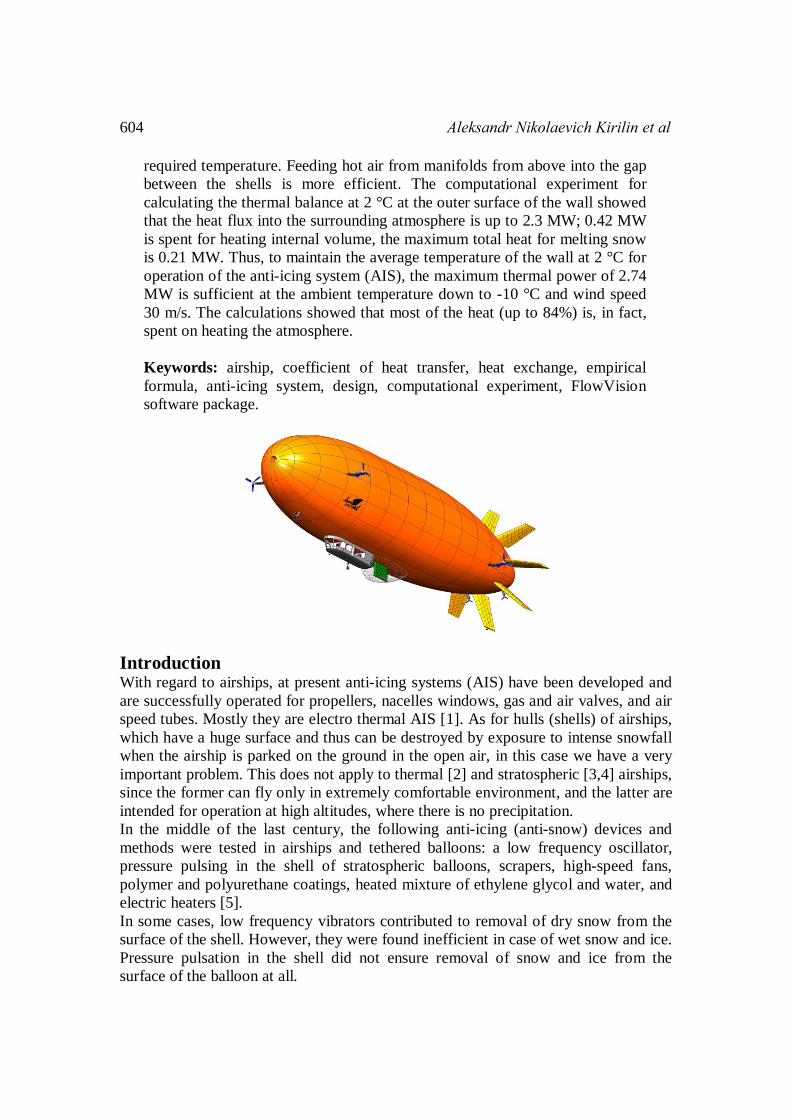
Introduction With regard to airships, at present anti-icing systems (AIS) have been developed and
are successfully operated for propellers, nacelles windows, gas and air valves, and air
speed tubes. Mostly they are electro thermal AIS [1]. As for hulls (shells) of airships,
which have a huge surface and thus can be destroyed by exposure to intense snowfall
when the airship is parked on the ground in the open air, in this case we have a very
important problem. This does not apply to thermal [2] and stratospheric [3,4] airships,
since the former can fly only in extremely comfortable environment, and the latter are
intended for operation at high altitudes, where there is no precipitation.
In the middle of the last century, the following anti-icing (anti-snow) devices and
methods were tested in airships and tethered balloons: a low frequency oscillator,
pressure pulsing in the shell of stratospheric balloons, scrapers, high-speed fans,
polymer and polyurethane coatings, heated mixture of ethylene glycol and water, and
electric heaters [5].
In some cases, low frequency vibrators contributed to removal of dry snow from the
surface of the shell. However, they were found inefficient in case of wet snow and ice.
Pressure pulsation in the shell did not ensure removal of snow and ice from the
surface of the balloon at all.
Thermal calculation of airship hull protection from snow 605
Scrapers were successfully used to remove dry and wet snow from most of the surface
of balloons located on ground holding devices. However, scrapers are ineffective for
removing snow from stabilizers and the aft.
High-speed fans were successfully used to remove dry and partly wet snow from the
surfaces of the tail-plane.
Polymer and polyurethane coatings do not prevent icing of surfaces.
An installation with a mixture of ethylene glycol and water can handle almost all
surfaces of aerostatic aircraft. Preheated ethylene glycol together with a scraper may
be used to remove ice from the top of the shell.
Electric heaters proved to be effective in preventing formation of ice on fans, gas and
air valves.
Based on the above, it may be concluded that snow and ice from both airships and
tethered balloons was mainly removed using mechanical and physico-chemical
methods. Experience has shown that these methods are cumbersome and ineffective
when used for aerostatic aircraft. However, it is known that in aviation thermal AIS
are used in most cases. Continuously operating air-and-heat AISes are the most
common and simple systems.
In case of constant heating, water droplets or wet snow that fall on the heated surface
do not freeze but roll off it with partial evaporation. When using thermal AISes, hot
air is supplied to the protected surface (wing, fins) to heat it to the required
temperature. Hot air is taken either from the compressor of the gas turbine, or from
the heat exchanger through which the exhaust gases escape. Sometimes the air is
heated by special gasoline heaters. Air heaters are also used. Introduction
Use of air-and-heat method of fighting with snow and ice should be a general
direction in development of AISes for airships of a new generation. To do so, airship
design should provide an "air gap" between the outer surface of the hull and gas
compartments, a system of channels for hot air, and heat exchangers or heaters.
Since in practice ice and wet snow do not significantly affect flying capacity of an
airship, the AIC for the hull and tail-plane should be calculated for parked vehicle.
Melting ice and snow on a large area, especially in severe icing conditions and in case
of very heavy snowfalls (over 20 kg/m² for 10 hours) requires higher energy
consumption. But, as preliminary calculations show, power of the propulsion unit
designed for cruising should be enough for intensive operation of airship's AIS when
it is parked in the open air.
This article is aimed at clarifying the required heat output for AIS operation and
computation research of variants of the airship hull heating system in order to select
the most energy-efficient solution that should fit into the existing design.
Non-stationary three-dimensional turbulent flow was computed using the FlowVision
2.5 software package [6]. This software has been under development for over twenty
years and is recognized by the engineering and university community as a fairly
reliable tool for computer simulation of heat and mass transfer in three-dimensional
turbulent flow [7,8]. The results of computer simulation are used for selecting the
empirical formula of heat transfer that can be used at the stage of design (TDA) for
rapid assessment of energy efficiency of a system in case of changes in the basic
606 Aleksandr Nikolaevich Kirilin et al
thermophysical parameters: temperature of heated wall, external air temperature, and
wind speed.
An important aspect of the problem is correct calculation of the interaction between
precipitation and surface of the aircraft. It is necessary to take into account particles
behavior in the boundary layer and the flow of liquid on the surface, as discussed in
several papers, e.g. [9,10]. This work takes into account the boundary layer, but it
shows that for an airship, it is not necessary to take into account fluid running down
the shell.
In building computational models, real geometrical dimensions of the airship hull
were used with the maximum diameter of 20.8 m and length of 104 m. The size of the
gap between the outer shell and the gas bag is 0.2 m. The volume of the airship was
26 thousand cubic meters. The required AIS heating power was calculated for varying
intensity of snowfall at outside temperatures varying from 0 to -10 °C and wind speed
varying from 0 to 30 m/s. Temperature of the outer wall of the airship hull was
assumed to be ≥ 2 ºC.
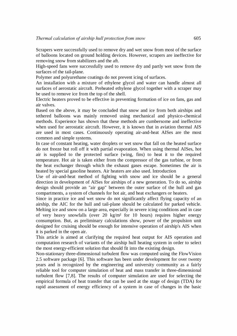
Choice of an Empirical formula for calculating the heat flux from the airship Airship's hull surface heat transfer depends on the turbulent flux that occurs due to
blowing with wind. It is assumed that the airship is attached to the landing site with a
mooring mast and a bow rope, that is, its hull acts as a weather vane, so we expect
that the wind is always directed along the hull of the airship. Simulation of wind
action was studied in a two-dimensional computation experiment on axisymmetric
model. To save time and computing resources, computational domain is limited by
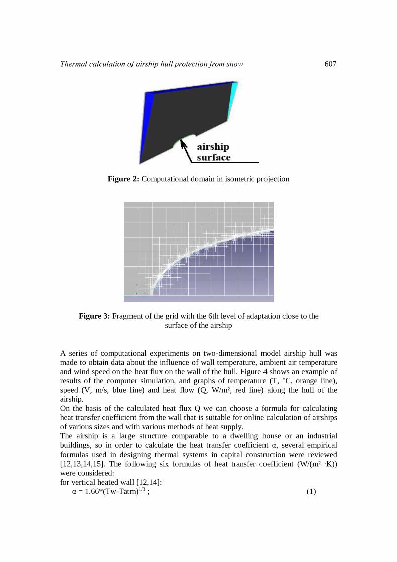
two planes, as shown in the front view in Figure 1 and in isometric projection in
Figure 2. The computational domain is limited by the 12 degrees sector in relation to
the axis of the airship hull. Adaptations of high level mesh (6 - 8) (Fig. 3) and a
standard k-ε turbulence model were used [6,11]. In setting the boundary conditions,
parameters recommended by ICAO in manual (ICAO, 1993) were used.
Figure 1: Front view of the computational domain
Thermal calculation of airship hull protection from snow 607
Figure 2: Computational domain in isometric projection
Figure 3: Fragment of the grid with the 6th level of adaptation close to the
surface of the airship
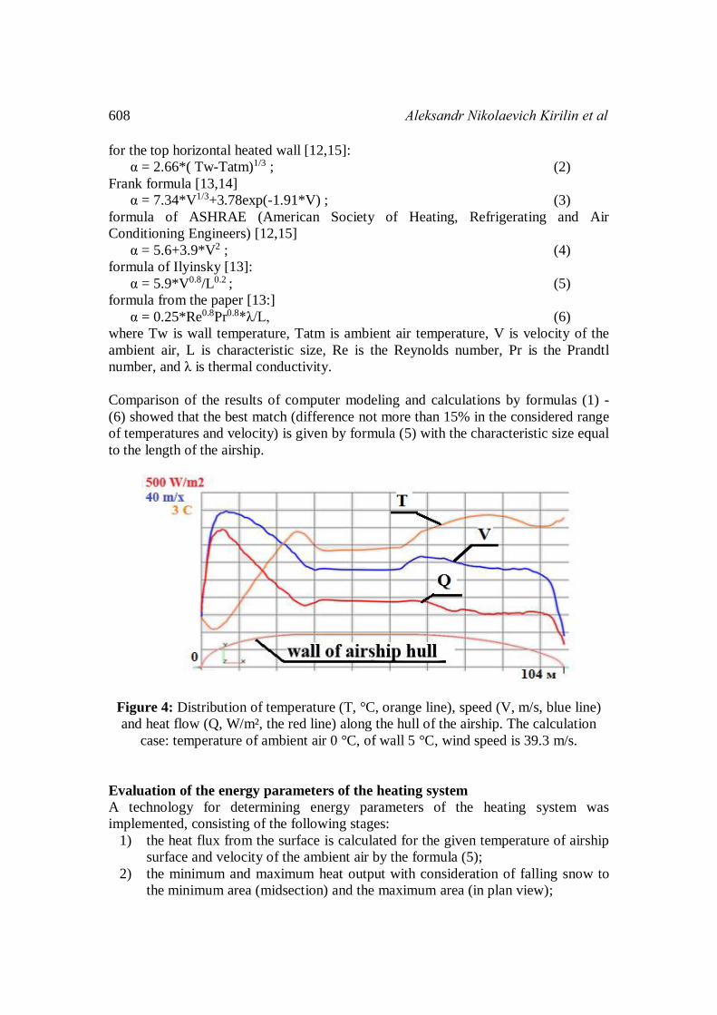
A series of computational experiments on two-dimensional model airship hull was
made to obtain data about the influence of wall temperature, ambient air temperature
and wind speed on the heat flux on the wall of the hull. Figure 4 shows an example of
results of the computer simulation, and graphs of temperature (T, °C, orange line),
speed (V, m/s, blue line) and heat flow (Q, W/m², red line) along the hull of the
airship.
On the basis of the calculated heat flux Q we can choose a formula for calculating
heat transfer coefficient from the wall that is suitable for online calculation of airships
of various sizes and with various methods of heat supply.
The airship is a large structure comparable to a dwelling house or an industrial
buildings, so in order to calculate the heat transfer coefficient α, several empirical
formulas used in designing thermal systems in capital construction were reviewed
[12,13,14,15]. The following six formulas of heat transfer coefficient (W/(m² ∙K))
were considered:
for vertical heated wall [12,14]:
α = 1.66*(Tw-Tatm)1/3 ; (1)
608 Aleksandr Nikolaevich Kirilin et al
for the top horizontal heated wall [12,15]:
α = 2.66*( Tw-Tatm)1/3 ; (2)
Frank formula [13,14]
α = 7.34*V1/3+3.78exp(-1.91*V) ; (3)
formula of ASHRAE (American Society of Heating, Refrigerating and Air
Conditioning Engineers) [12,15]
α = 5.6+3.9*V2 ; (4)
formula of Ilyinsky [13]:
α = 5.9*V0.8/L0.2 ; (5)
formula from the paper [13:]
α = 0.25*Re0.8Pr0.8*λ/L, (6)
where Tw is wall temperature, Tatm is ambient air temperature, V is velocity of the
ambient air, L is characteristic size, Re is the Reynolds number, Pr is the Prandtl
number, and λ is thermal conductivity.
Comparison of the results of computer modeling and calculations by formulas (1) -
(6) showed that the best match (difference not more than 15% in the considered range
of temperatures and velocity) is given by formula (5) with the characteristic size equal
to the length of the airship.
Figure 4: Distribution of temperature (T, °C, orange line), speed (V, m/s, blue line)
and heat flow (Q, W/m², the red line) along the hull of the airship. The calculation
case: temperature of ambient air 0 °C, of wall 5 °C, wind speed is 39.3 m/s.
Evaluation of the energy parameters of the heating system
A technology for determining energy parameters of the heating system was
implemented, consisting of the following stages:
1) the heat flux from the surface is calculated for the given temperature of airship
surface and velocity of the ambient air by the formula (5);
2) the minimum and maximum heat output with consideration of falling snow to
the minimum area (midsection) and the maximum area (in plan view);

Thermal calculation of airship hull protection from snow 609
3) motion of snowflakes around the airship is calculated for clarifying the area
covered with snow;
4) variants of AIS design are chosen;
5) for the chosen AIS variants, heat flux from the surface of the airship section
and temperature distribution on the surface of the airship section are calculated
(in three-dimensional layout basing on design features of the heating system
and on internal volume of the airship); and
6) for the best AIS variant the required total thermal power for AIS operation is
evaluated.
A. Result of step 1-5 of definition of AIS energy parameters
Phases 1 and 2 are shown in Figure 5, taking into account the fact that the midsection
area (339.8 m²) was taken as the minimum area of snowfall, and the area of the
horizontal projection of the airship (1786 m2) as the maximum area. The surface area
of the airship without fins was estimated at 5733 m². Preliminary assessment shows
the required thermal power for AIS operation of 3 MW.
Figure 5: Thermal power Q required for AIS operation with the minimum (a) and the maximum (b) area of snowfall. The vertical axis is AIS power in kW.
The horizontal axis is wind speed in m/s.
Computer simulation (step 3) of snow falling onto the body of the airship was made
with the assumption that the particles that touch the surface leave the computational
domain. Since the test particles in the FlowVision software suite are spherical, their
diameter and particle density in the calculation set correspond to snowflakes with
weight of 0.004 g and diameter of 5 mm. Figure 6 shows that the maximum
concentration of snow was observed on the top of the airship hull in the sector about
60 degrees. Based on these data about distribution of snow on the surface of the
airship, we can choose the layout of collectors for supplying hot air to designed AIS.
In Figure 6 separate, unrelated areas of high concentration of snow are due to the
technology of test particles - snowflakes start from points evenly distributed in space.

610 Aleksandr Nikolaevich Kirilin et al
Figure 6: Distribution of snow concentration on the surface of the airship hull. Speed
of wind 15 m/sec (flow from left to right). Red dots visualize test particles - flakes.
In step 4, two variants of supplying hot air to heat the outer surface of the airship were
considered:
- the simpler method of supplying from below into the space between the outer and
the inner shells (Figure 7);
- a more sophisticated method of feeding hot air from above through manifolds
into the gap between the outer and the inner shells (Figure 8).
In stage 5, one section of the airship hull corresponding to the actual size of the
section in the middle of the chassis (Figure 7-a) was used for calculation model. The
computational domain consists of three sub-areas: airship hull, sub-domain with
helium gas bag, sub-domain of the gas bag with air and outer sub-domain that
simulates the ambient air.
In the first case, heaters are located one by one on the left and the right side of the
airship at the bottom near the gap. Terms of numerical experiment are as follows:
initial temperature of helium and air 0 °C, air temperature at the outlet of heaters 50
°С; area of heaters 0.0353 m2; air flow rate at the outlet of the heaters 1.4 kg/s; air
velocity at the outlet of the heaters 33.7 m/s; external surface area 522 m², wind speed
15 m/s.
A computational experiment showed that a strong convective flow occurs in the
volume of helium that equalize temperature in the volume, and therefore the local
temperature differs from the average by no more than 5%. 50 minutes after the start of
heating, steady state is not reached, helium continues to heat up. The average
temperature of the outer surface is 6.3 °C, the average temperature of helium is 8 °C.
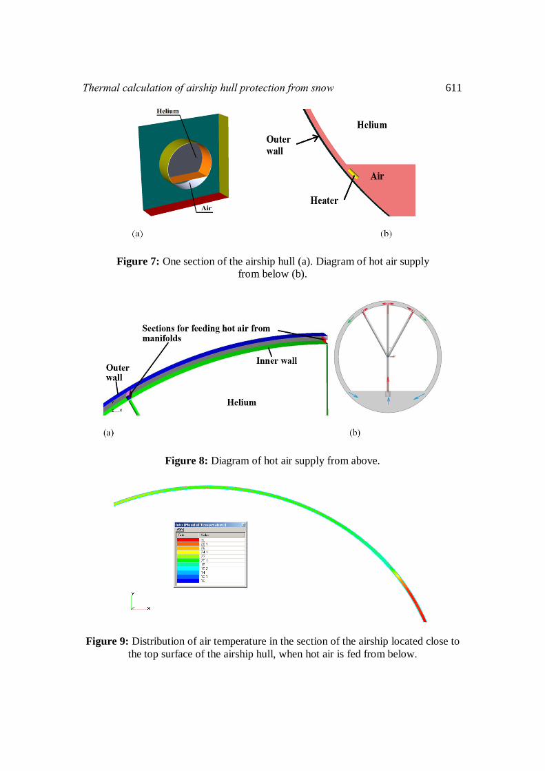
The main heat flow goes to heating air in the lower half of the airship (see Figure 9),
causing a powerful thermal flux to the atmosphere from the surface of the bottom of
the airship, where there is no snow. Thus, this design is not efficient.
Thermal calculation of airship hull protection from snow 611
Figure 7: One section of the airship hull (a). Diagram of hot air supply
from below (b).
Figure 8: Diagram of hot air supply from above.
Figure 9: Distribution of air temperature in the section of the airship located close to
the top surface of the airship hull, when hot air is fed from below.
612 Aleksandr Nikolaevich Kirilin et al
In the second variant, hot air is fed through three manifolds to the top part of the
airship hull (Figure 8). Hot air outlet from the central manifold is located in the
uppermost part and extends parallel to the axis of the airship. The other two outlets of
manifolds are located parallel to the first one, and are located at the angle +/-30° to it,
in accordance with the results of snowfall calculations (Figure 6). Terms of the
computer modeling are similar to the previously discussed scheme of the hot air
supply from below.
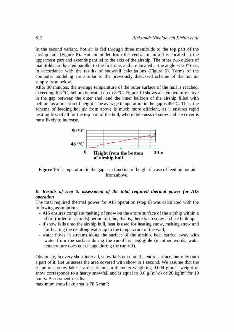
After 30 minutes, the average temperature of the outer surface of the hull is reached,
exceeding 6.3 °C, helium is heated up to 8 °C. Figure 10 shows air temperature curve
in the gap between the outer shell and the inner balloon of the airship filled with
helium, as a function of height. The average temperature in the gap is 49 °C. Thus, the
scheme of feeding hot air from above is much more efficient, as it ensures rapid
heating first of all for the top part of the hull, where thickness of snow and ice cover is
most likely to increase.
Figure 10: Temperature in the gap as a function of height in case of feeding hot air
from above.
B. Results of step 6: assessment of the total required thermal power for AIS
operation
The total required thermal power for AIS operation (step 6) was calculated with the
following assumptions:
- AIS ensures complete melting of snow on the entire surface of the airship within a
short (order of seconds) period of time, that is, there is no snow and ice buildup;
- if snow falls onto the airship hull, heat is used for heating snow, melting snow and
for heating the resulting water up to the temperature of the wall;
- water flows in streams along the surface of the airship, heat carried away with
water from the surface during the runoff is negligible (in other words, water
temperature does not change during the run-off).
Obviously, in every short interval, snow falls not onto the entire surface, but only onto
a part of it. Let us assess the area covered with show in 1 second. We assume that the
shape of a snowflake is a disc 5 mm in diameter weighting 0.004 grams, weight of
snow corresponds to a heavy snowfall and is equal to 0.6 g/(m²∙c) or 20 kg/m² for 10
hours. Assessment results:
maximum snowflake area is 78.5 mm²;
Thermal calculation of airship hull protection from snow 613
specific amount of snowflakes is calculated as
<weight of snow per second per 1 m² of the horizontal surface>/<average weight of a
snowflake> = 0.6/0.004 = 150 pcs/m²;
the specific area covered by snow within 1 s is defined as <specific amount of
snowflakes> *<maximum area of a snowflake> = 11,775 mm² (0.012 m²);
or 1.2%
Thus, it can be concluded that every second the snow falls on the area not exceeding
0.6% of the surface area of the airship (taking into account that the probability of
snow contact and holding on the bottom surface is negligible). On this basis, in
calculating the heat flux from the surface of the airship, the share of the surface
covered with snow is neglected. The surface of the airship is believed convex, so the
water does not stay on the surface and flows down. The time of the film running off in
the gravity field is at least 2 seconds, therefore as the top assessment we assume that
the water has enough time to warm up to the temperature of the wall. The maximum
amount of heat required for heating snow, melting snow for heating the resulting
water up to the temperature of the wall (2°C) is 220 J/(m²∙s), based on data [16,17].
Computer modeling experiment for calculating the heat balance for a 104 m long
airship, composed of 13 gas sections, at the temperature of external surface of the wall
of 2°C, shows that the heat flow to the surrounding atmosphere (-10°C and wind
speed of 30 m/s) is 2.3 MW. According to formula (2), heating of the internal volume
requires 0.42 MW, and the maximum total heat required for melting snow is 0.21
MW (snow falls onto the area equal to 1/6 of the surface area of the airship). Thus, if
the average temperature of the wall is maintained at 2 °C, the maximum thermal
power of 2.74 MW is sufficient for AIS operation at the ambient temperature down to
-10 °C and wind speed up to 30 m/s.
Conclusion 1. In computer simulation of blowing the airship hull with wind, calculation of the
heat flux from the surface of the airship in axisymmetric environment makes it
possible to determine an empirical formula for the heat transfer coefficient (5)
with the accuracy of 15% from work [13], depending on hull size and speed of
flight for preliminary calculations of the heat flow.
2. On the basis of computational experiments, a conclusion can be made that
feeding hot air into the bottom compartment, or from below into the gap
between the shells is inefficient from the standpoint of the upper surface of the
airship reaching the required temperature. Feeding hot air from manifolds from
above into the gap between the shells is more efficient.
3. Computer modeling made it possible to adjust the required thermal power for
AIS operation by about 10% upwards.
4. The maximum thermal power required to ensure efficient AIS operation at a
middle-size airship at the ambient temperature of -10 °C and wind speed of 30
614 Aleksandr Nikolaevich Kirilin et al
m/s is 2.74 MW. In less severe weather conditions (ambient temperature of -5
°C and wind speed of 20 m/s), the required AIS heat will be twice lower.
The computations showed that most of the heat (up to 84%) is, in fact, spent on
heating the atmosphere. In this situation, particular importance has the maximum
accurate estimation of the heat flow to the atmosphere, which is associated with the
best simulation of turbulence near the wall, the internal volume heated and the heat
flux through the material of the wall. Comparison of different turbulence models is of
interest for choosing the model that is the best for simulating separating flows. It is
supposed to use a set of models and their modifications similar to [18] for obtaining a
more complete vision on applicability of turbulence models used in [18]. For correct
computation of the heat used for melting snow in different conditions, we further
propose to use the methods [19]. The second, applied area of the work is the
consideration of various systems for feeding hot air from manifolds on top into the
gap between the shells with consideration of flow in the manifolds in order to find the
required thermal and mechanical power in different weather conditions.
References
[1] M.G. Akopov, M.I. Bekasov, V.G. Dolgushev, “Aircraft Equipment Systems:
Textbook for Students of Higher Technical Educational Institutions”. -
Moscow: Mechanical Engineeringm 2005.
[2] Oi, Song, “The Simulation and Analysis of Diurnal Different Temperature in
the Process of Station of Stratospheric Airships”, In the Proceedings of 9th
International Airship Conference, Ashford, 2012.
[3] K.L. Busemeyer, “Hot Air Airships. Airship Technology”, Cambridge:
Cambridge University Press, 2012.
[4] A.A. Boldyreva, “Daily Temperature Fluctuations of the Altitude of
Stratospheric Platform and Methods of Compensation thereof. System
Analysis, Management and Information Processing”. In the Proceedings of the
III International Scientific Workshop, Settl. Divnomorskoe, Sep 27. - Oct 2,
DSTU. Rostov-On-Don, 2012.
[5] A.N. Kirilin, “Airships”. - Moscow: MAI-PRINT Publishing House, 2013.
[6] Software package for gas and fluid flow simulation FlowVision. Version 2.5.0.
Manual CAPVIDIA, 1999-2007. Leuven, Belgium.
[7] A. Aksenov, A. Dyadkin, V. Pokhilko, “Overcoming of Barrier between CAD
and CFD by Modified Finite Volume Method”, In the Proceedings of “1998
ASME Pressure Vessels and Piping Division Conference”, San Diego, ASME
PVP, vol. 377-1, pp. 79-83, 1998.
[8] A.S. Shishaeva, A.A. Aksenov, S.V. Zhluktov, N.F. Kudimov, E.E. Son, M.D.
Taran, O.N. Tretyakov, “About Modeling Complex Heat Transfer in High
Power Transformers”, Bulletin of RAS: Energy, vol. 2, pp.131-140, 2013.
URL: http://scholar.google.ru/citations?view_op=view_citation&hl=ru&user=
Thermal calculation of airship hull protection from snow 615
OmI6J6gAAAAJ&pagesize=100&citation_for_view=OmI6J6gAAAAJ:dBIO0
h50nwkC.
[9] A.L. Stasenko, “Physical Mechanics of Multiphase Flows”. - Moscow: MIPT,
2004.
[10] A.L. Stasenko, V.A. Tolstoy, D.A. Shirobokov, “Re. Aircraft Icing: Dynamics
of Drops and Wetting Surface”, Mathematical Modeling, vol. 13 (6), pp. 81-86,
2001. URL: http://www.mathnet.ru/rus/mm734
[11] D.C. Wilcox, “Turbulence Modeling for CFD”. – USA: DCW Industries, Inc.
1994.
[12] E.G. Malyavina, “Heat Loss of a Building: Handbook”. - Moscow: AVOK-
PRESS, 2007.
[13] IV.M. lyinsky, “Construction Thermal Physics (Envelope and the Micro-
Climate of Buildings): A Handbook for Construction and Engineering
Universities”. - Moscow: Vysshaya Shkola, 1974.
[14] A.M. Shklover, B.F. Vasiliev, F.V.Ushkov, “Fundamentals of Thermal
Engineering of Residential and Public Buildings”. - Moscow: Gosstroyizdat,
1956.
[15] ASHRAE Fundamentals (1985). ASHRAE.
[16] N.V. Vargaftik, “Handbook of Thermo-Physical Properties of Gases and
Liquids”. - Moscow: Nauka (Science), 1972.
[17] D.H. Male, D.M. Gray, “Handbook of Snow: Principles, Processes,
Management And Use. By Item 1-932846-06-9”. – Caldwell: The Blackburn
Press, 1981.
[18] I.E. Ivanov, I.A. Kryukov, E.V. Larina, “Influence of Turbulent Viscosity
Relaxation Time on Simulation of Flows in Nozzles and Jets”, Bulletin of
RAS: Mechanics of Fluids and Gases, vol. 5, pp. 149-159, 2014.
[19] N.N. Svetushkov, “The Method of Geometric Integrals in Modeling Heat
Transfer Processes in Phase Transformation Problems”, Bulletin of the
Moscow Aviation Institute, vol. 19 (5), pp. 182-186, 2012.
[20] International Civil Aviation Organization, Manual of the ICAO Standard
Atmosphere (extended to 80 kilometres (262 500 feet)), Doc 7488-CD, Third
Edition, 1993, ISBN 92-9194-004-6. URL: http://en.wikipedia.org/wiki/
International_Civil_Aviation_Organizationhttp://en.wikipedia.org/wiki/Special
:BookSources/9291940046

616 Aleksandr Nikolaevich Kirilin et al