Embed Size (px)
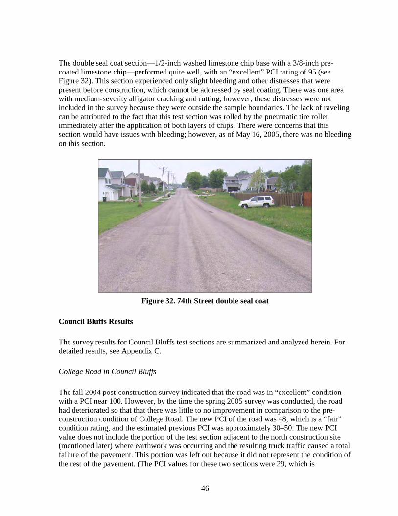
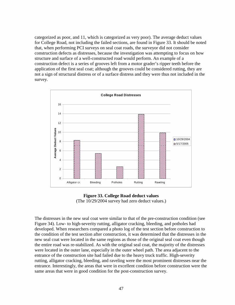
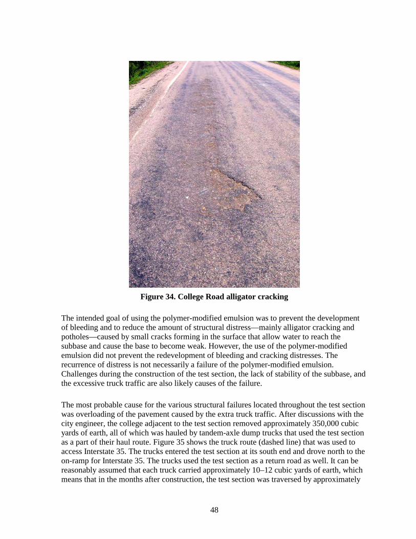
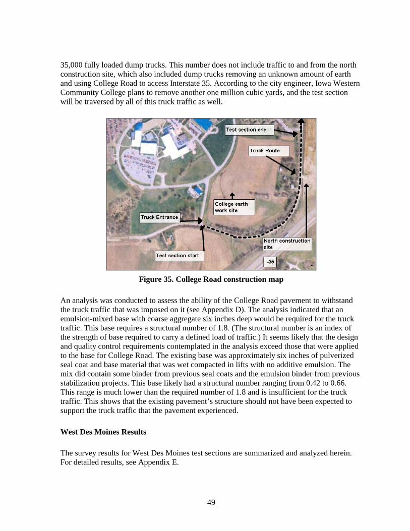
Citation preview
Thin Maintenance Surfaces for Municipalities
Final Report May 2007
Sponsored by the Iowa Highway Research Board (IHRB Project TR-507) and the Iowa Department of Transportation (CTRE Project 03-161)
Iowa State Universityrsquos Center for Transportation Research and Education is the umbrella organization for the following centers and programs Bridge Engineering Center bull Center for Weather Impacts on Mobility
and Safety bull Construction Management amp Technology bull Iowa Local Technical Assistance Program bull Iowa Traffi c Safety Data Service bull Midwest Transportation Consortium bull National Concrete Pavement
Technology Center bull Partnership for Geotechnical Advancement bull Roadway Infrastructure Management and Operations Systems bull Statewide Urban Design and Specifications bull Traffic Safety and Operations
About CTREISU
The mission of the Center for Transportation Research and Education (CTRE) at Iowa State Unishyversity is to develop and implement innovative methods materials and technologies for improvshying transportation efficiency safety and reliability while improving the learning environment of students faculty and staff in transportation-related fi elds
Disclaimer Notice
The contents of this report reflect the views of the authors who are responsible for the facts and the accuracy of the information presented herein The opinions findings and conclusions expressed in this publication are those of the authors and not necessarily those of the sponsors
The sponsors assume no liability for the contents or use of the information contained in this document This report does not constitute a standard specification or regulation
The sponsors do not endorse products or manufacturers Trademarks or manufacturersrsquo names appear in this report only because they are considered essential to the objective of the document
Non-discrimination Statement
Iowa State University does not discriminate on the basis of race color age religion national origin sexual orientation gender identity sex marital status disability or status as a US veteran Inquiries can be directed to the Director of Equal Opportunity and Diversity (515) 294-7612
Technical Report Documentation Page
1 Report No IHRB Project TR-507
2 Government Accession No 3 Recipientrsquos Catalog No
4 Title and Subtitle Thin Maintenance Surfaces for Municipalities
5 Report Date May 2007
6 Performing Organization Code
7 Author(s) Charles Jahren Duane Smith and Cliff Plymesser
8 Performing Organization Report No CTRE Project 03-161
9 Performing Organization Name and Address Center for Transportation Research and Education
Iowa State University
2711 South Loop Drive Suite 4700
Ames IA 50010-8664
10 Work Unit No (TRAIS)
11 Contract or Grant No
12 Sponsoring Organization Name and Address Iowa Highway Research Board
Iowa Department of Transportation
800 Lincoln Way
Ames IA 50010
13 Type of Report and Period Covered Final Report
14 Sponsoring Agency Code
15 Supplementary Notes Visit wwwctreiastateedu for color PDF files of this and other research reports
16 Abstract As streets age officials must deal with rehabilitating and reconstructing these pavements to maintain a safe and comfortable ride In light of nationwide budget shortfalls cost-effective methods of extending pavement service life must be developed or the overall condition of street systems will continue to fall Thin maintenance surfaces (TMSs) are a set of cost-effective preventive maintenance surfacing techniques that can be used to extend the life of bituminous pavementmdashpavement built with hot mix asphalt hot mix asphalt overlays of portland cement concrete pavements built-up seal coat (chip seal) stabilized materials or a combination of these
While previous phases of TMS research have provided information about the uses of thin maintenance surfaces in rural settings urban areas have different road maintenance challenges that should be considered separately This research provides city street officials with suggestions for TMS techniques that street departments can easily test and include into their current programs This research project facilitated the construction of TMS test sections in Cedar Rapids Council Bluffs and West Des Moines (all urban settings in Iowa) Test section sites and surfaces were selected to suit the needs of municipalities and were applied to roads with an array of various distresses and maintenance needs Condition surveys of each test section were performed before construction after construction and after the first winter to record the amount and severity of existing distress and calculate the pavement condition index
Because conditions of the test sections varied greatly determining which surface was most successful by comparing case studies was not feasible However some general conclusions can be made from this research TMSs are suitable preventive maintenance techniques for a municipal street departmentrsquos program for preserving existing pavements Careful attention should be paid to proper planning quality control during construction aggregate and binder selection and aggregate embedment in order to support successful TMS application
17 Key Words chipmatmdashfog sealmdashmicro-surfacingmdashseal coatmdashslurry sealmdashthin overlays
18 Distribution Statement No restrictions
19 Security Classification (of this report) Unclassified
20 Security Classification (of this page) Unclassified
21 No of Pages
74 plus appendices
22 Price
NA
Form DOT F 17007 (8-72) Reproduction of completed page authorized
THIN MAINTENANCE SURFACES FOR
MUNICIPALITIES
Final ReportMay 2007
Principal Investigator Charles Jahren
Associate Professor of Civil Construction and Environmental EngineeringIowa State University
Co-Principal Investigator Duane Smith
Associate Director for Outreach Center for Transportation Research and Education Iowa State University
Research Assistant Cliff Plymesser
Authors Charles Jahren Duane Smith and Cliff Plymesser
Sponsored bythe Iowa Highway Research Board
(IHRB Project TR-507)
Preparation of this report was financed in part through funds provided by the Iowa Department of Transportation
through its research management agreement with theCenter for Transportation Research and Education
CTRE Project 03-161
A report from Center for Transportation Research and Education
Iowa State University 2711 South Loop Drive Suite 4700
Ames IA 50010-8664 Phone 515-294-8103 Fax 515-294-0467
wwwctreiastateedu
TABLE OF CONTENTS
ACKNOWLEDGEMENTS IX
EXECUTIVE SUMMARY XI
INTRODUCTION1
Rationale 1 Research Objectives3 Study Methodology3 Pavement Condition Survey Procedure 5
THIN MAINTENANCE SURFACES6
Seal Coat (Chip Seal)6 Chipmat8 Slurry Seal8 Micro-surfacing9 Fog Seal 9 Thin HMA Overlays Smooth Seal and Other Thin Overlays 10 Decision Matrix for TMSs11
LITERATURE REVIEW12
Seal Coating 12 Chipmat13 Fog Seal 14 Micro-surfacing14 LTPPSPS-3 Preventive Maintenance Study 15
TEST SECTION DESCRIPTION AND CONSTRUCTION16
Cedar Rapids Test Sections 16 Vermont Avenue16 Vermont Avenue Construction 18 74th Street 22 74th Street Construction 22
Council Bluffs Test Section 28 College Road28 College Road Construction 31
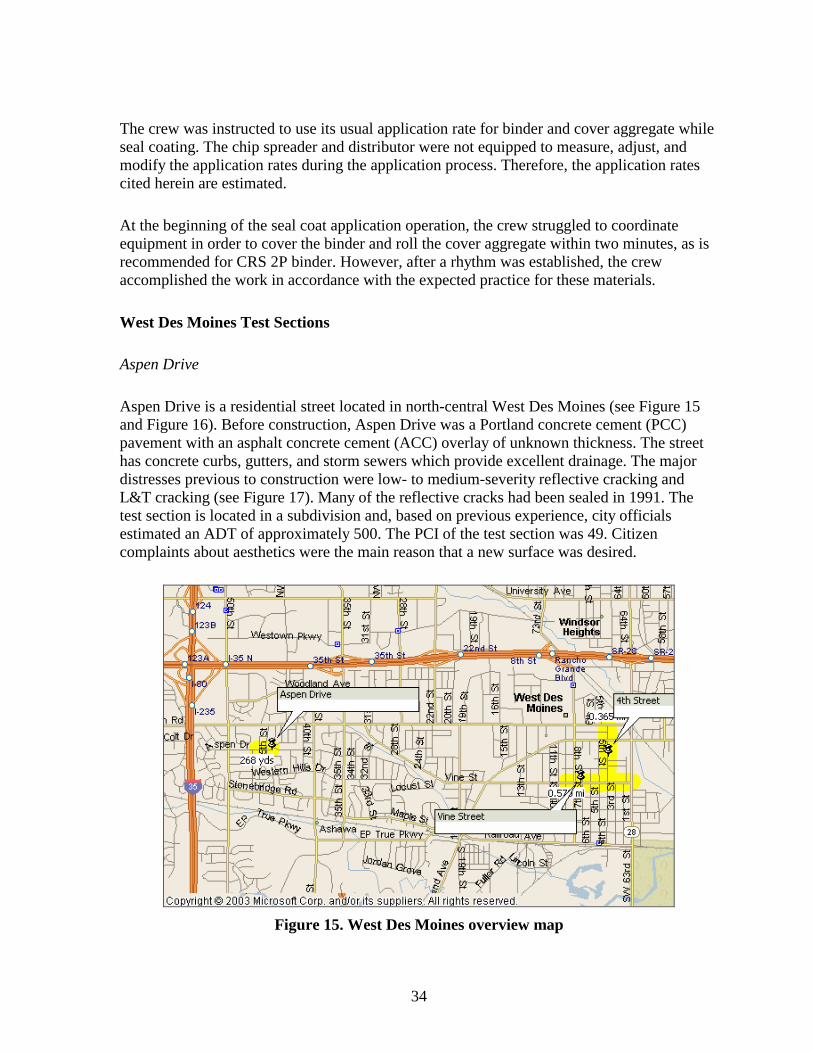
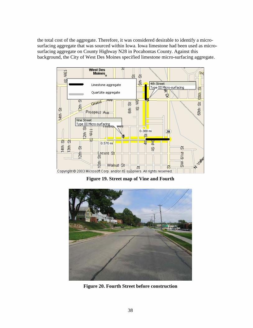
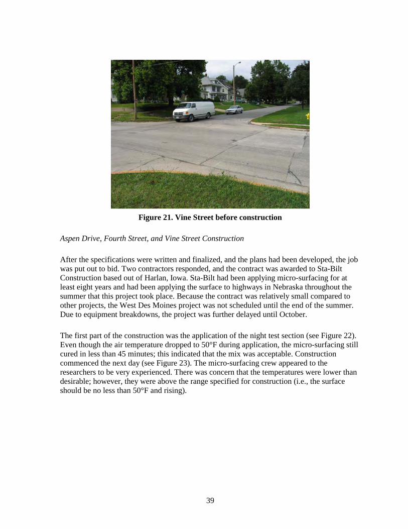
West Des Moines Test Sections34 Aspen Drive 34 Fourth Street and Vine Street37 Aspen Drive Fourth Street and Vine Street Construction39
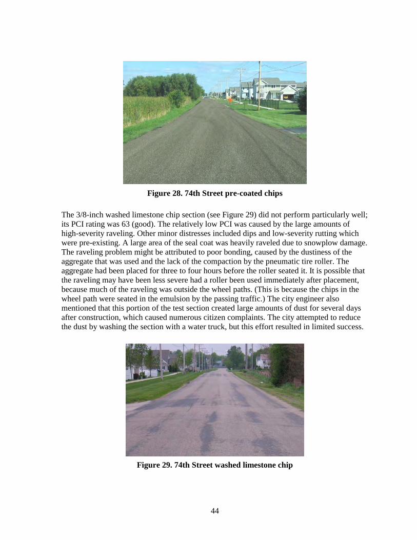
RESULTS AND DISCUSSION 41
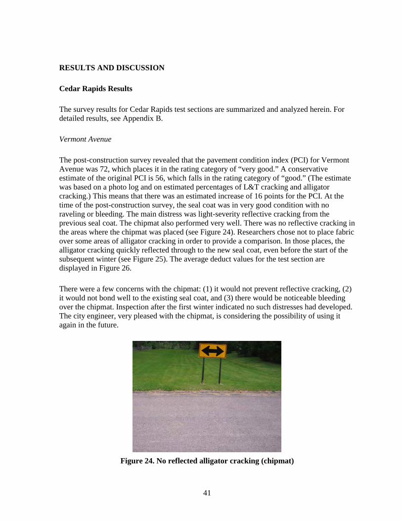
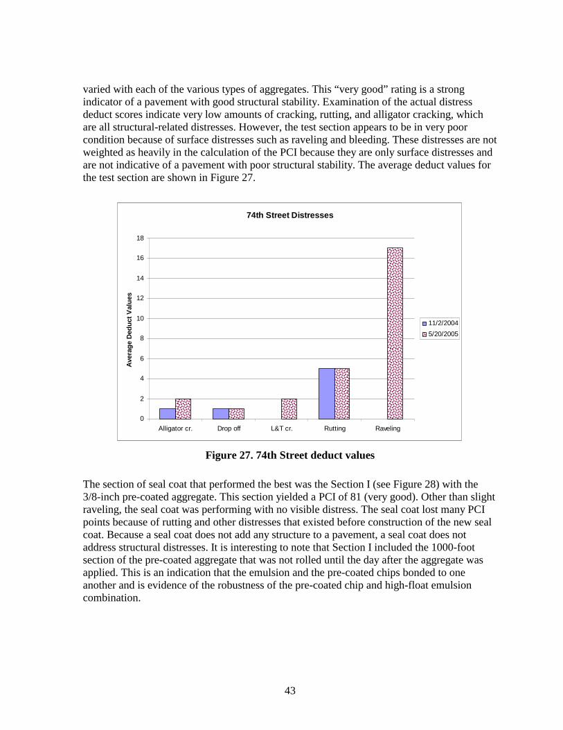
Cedar Rapids Results 41Vermont Avenue41
v
74th Street in Cedar Rapids 42 Council Bluffs Results 46
College Road in Council Bluffs 46 West Des Moines Results 49
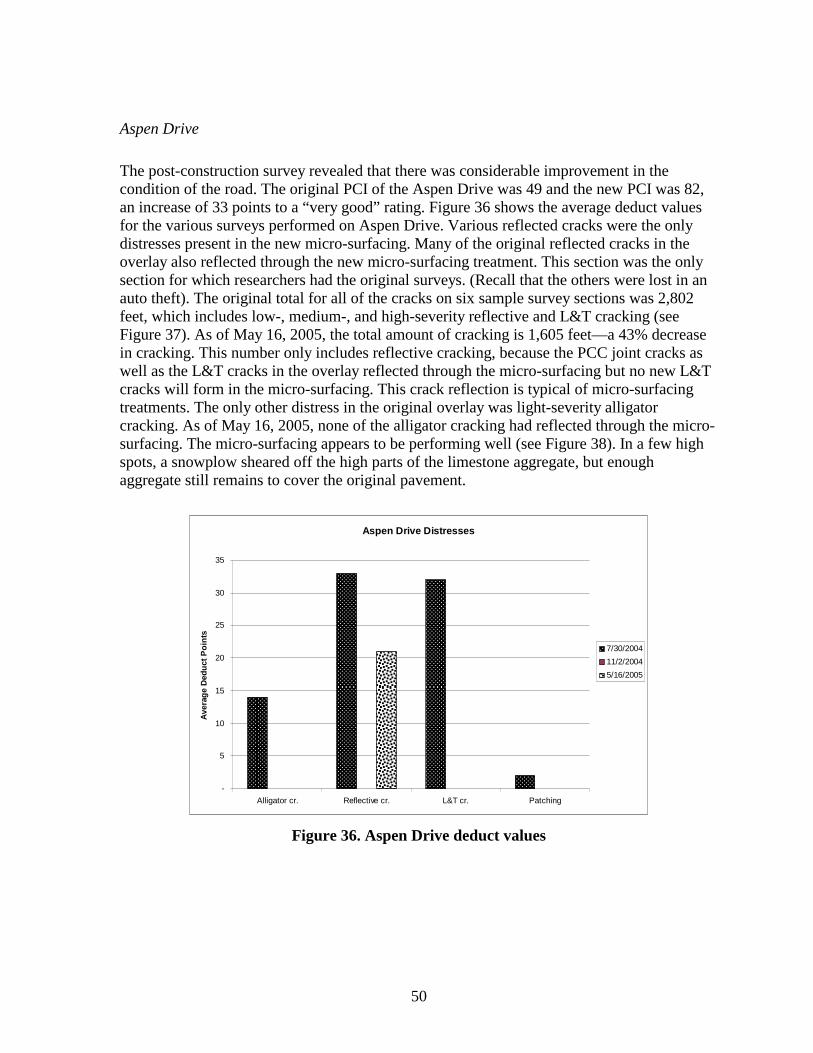
Aspen Drive 50 Fourth Street and Vine Street52
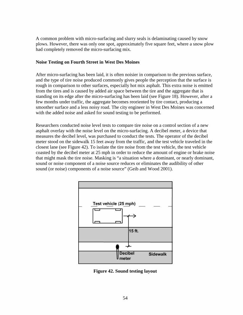
Noise Testing on Fourth Street in West Des Moines54 Additional Testing 57
CONCLUSIONS AND RECOMMENDATIONS 58
Cedar Rapids Conclusions 58 Council Bluffs Conclusions 58 West Des Moines Conclusions 59 General Conclusions 59Recommendations60
REFERENCES 61
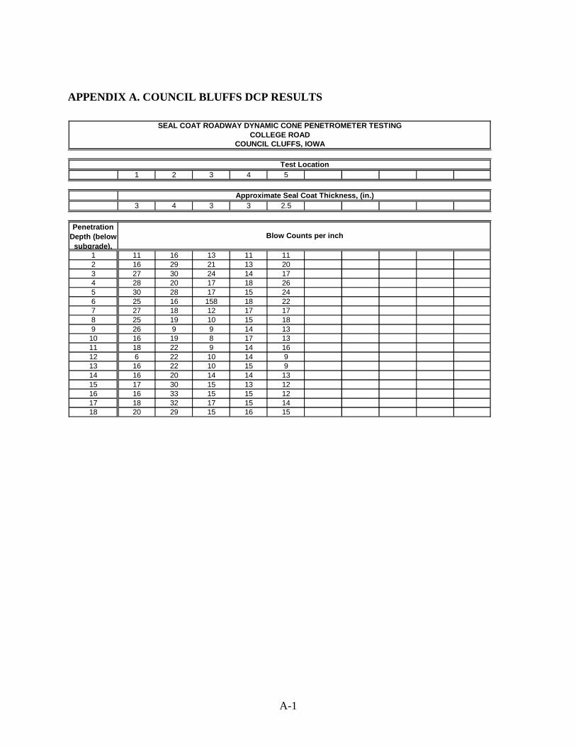
APPENDIX A COUNCIL BLUFFS DCP RESULTS A-1
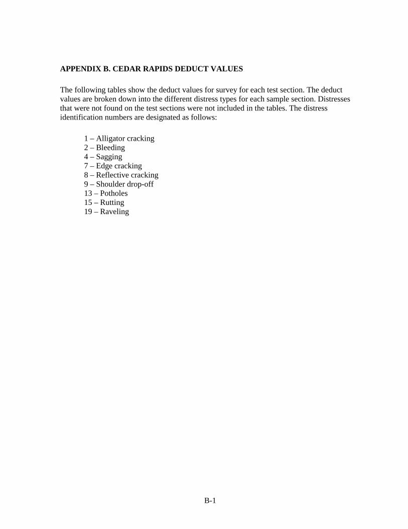
APPENDIX B CEDAR RAPIDS DEDUCT VALUESB-1
APPENDIX C COUNCIL BLUFFS DEDUCT VALUES C-1
APPENDIX D COUNCIL BLUFFS PAVEMENT DESIGN D-1
APPENDIX E WEST DES MOINES DEDUCT VALUESE-1
APPENDIX F NOVEMBER 2005 INSPECTION RESULTSF-1
APPENDIX G WEST DES MOINES SOUND RESULTS G-1
vi
LIST OF FIGURES
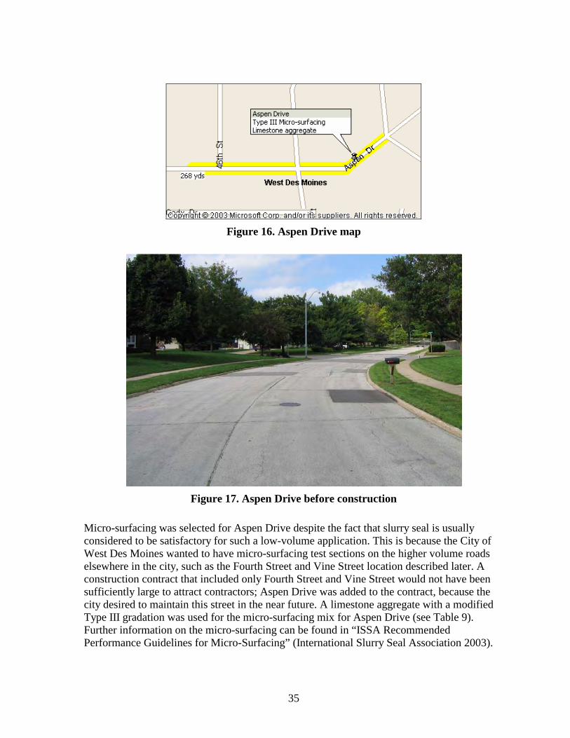
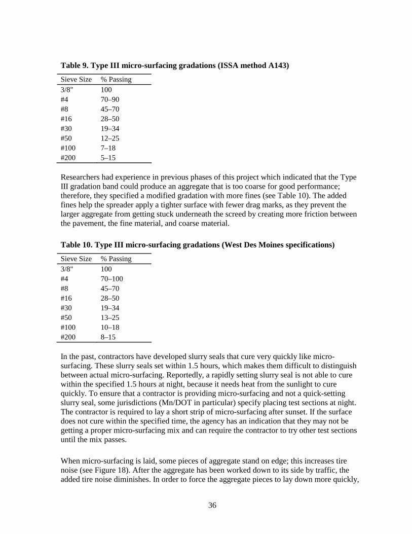
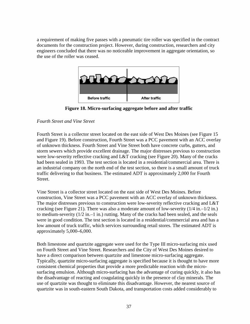
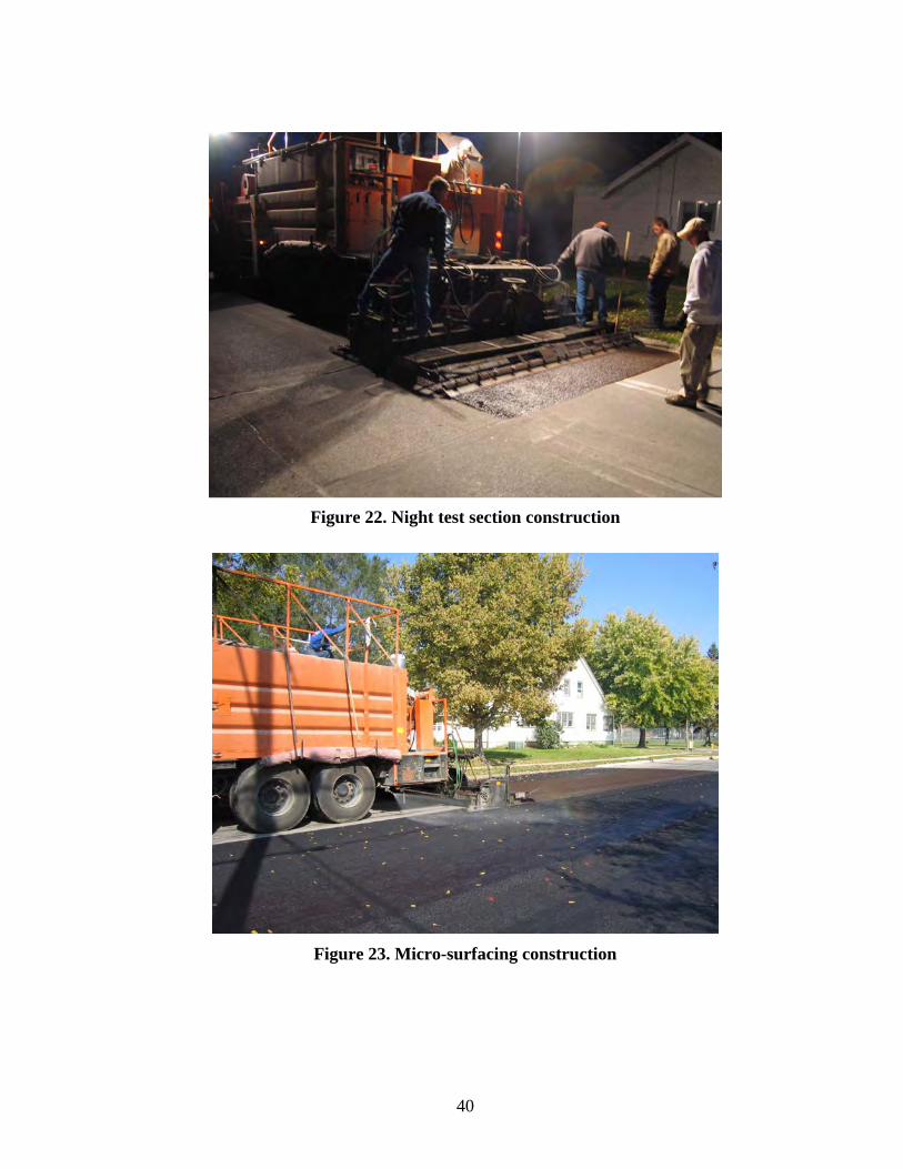
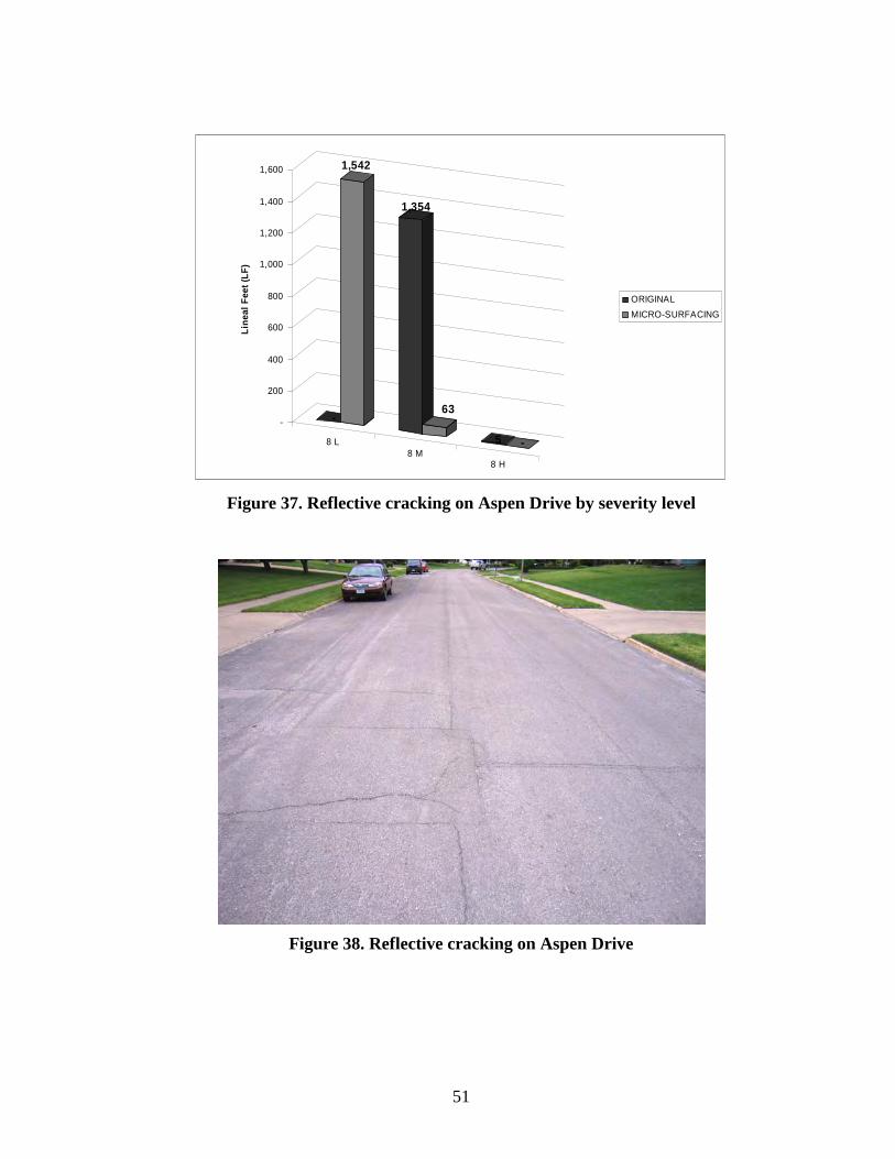
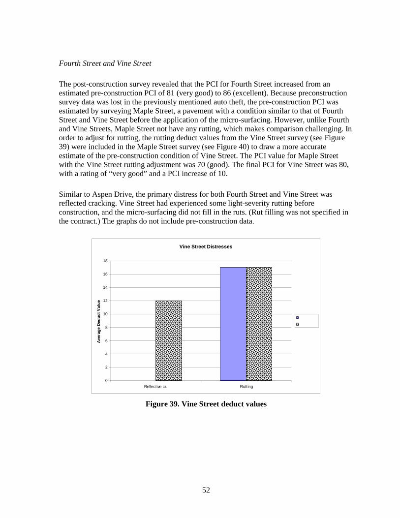
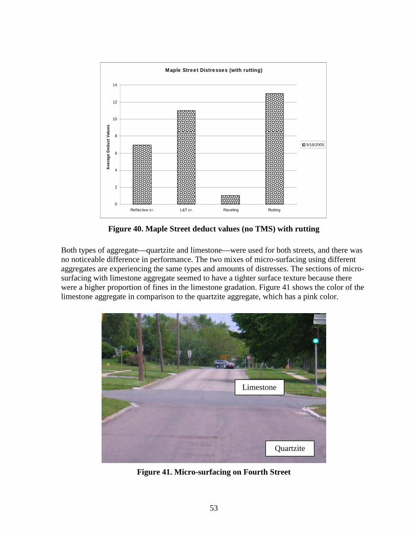
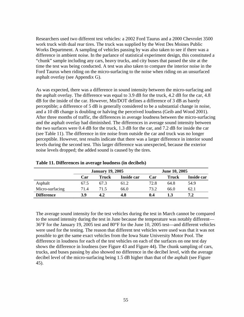
Figure 1 Municipal test section locations 16Figure 2 Vermont Avenue overview map17Figure 3 Vermont Avenue test section layout17Figure 4 Alligator cracking on Vermont Avenue 18Figure 5 Placement of the fabric in the tack coat19Figure 6 Cedar Rapids emulsion21Figure 7 74th Street overview map 22Figure 8 74th Street (dark areas are bleeding) 23Figure 9 74th Street test section layout 25Figure 10 Seal coat construction on 74th Street 27Figure 11 College Road overview map29Figure 12 College Road map 30Figure 13 College Road alligator cracking potholes and bleeding 30Figure 14 Stabilization of College Road33Figure 15 West Des Moines overview map 34Figure 16 Aspen Drive map 35Figure 17 Aspen Drive before construction 35Figure 18 Micro-surfacing aggregate before and after traffic 37Figure 19 Street map of Vine and Fourth 38Figure 20 Fourth Street before construction 38Figure 21 Vine Street before construction 39Figure 22 Night test section construction 40Figure 23 Micro-surfacing construction40Figure 24 No reflected alligator cracking (chipmat)41Figure 25 Reflected alligator cracking (no chipmat) 42Figure 26 Vermont Avenue deduct values42Figure 27 74th Street deduct values43Figure 28 74th Street pre-coated chips 44Figure 29 74th Street washed limestone chip 44Figure 30 74th Street pea rock 45Figure 31 Dusty washed limestone and dirty pea rock chips 45Figure 32 74th Street double seal coat 46Figure 33 College Road deduct values 47Figure 34 College Road alligator cracking 48Figure 35 College Road construction map49Figure 36 Aspen Drive deduct values 50Figure 37 Reflective cracking on Aspen Drive by severity level51Figure 38 Reflective cracking on Aspen Drive51Figure 39 Vine Street deduct values 52Figure 40 Maple Street deduct values (no TMS) with rutting 53Figure 41 Micro-surfacing on Fourth Street 53Figure 42 Sound testing layout 54Figure 43 First sound readings (in order of intensity)56
vii
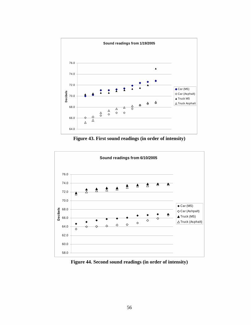
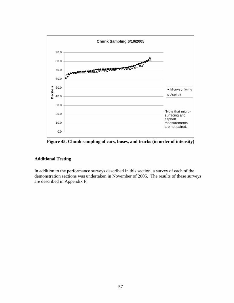
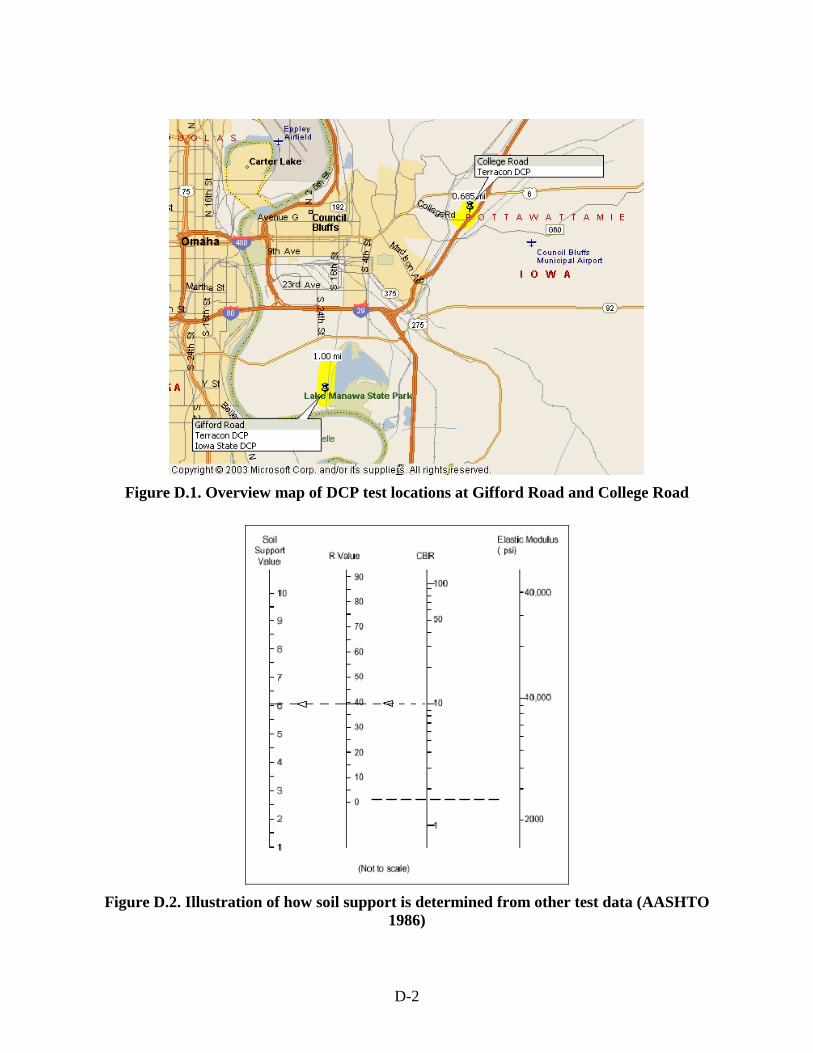
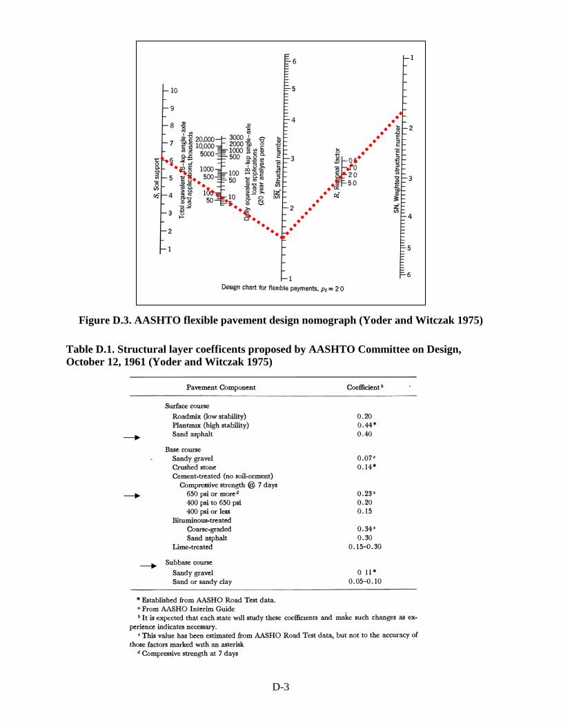
Figure 44 Second sound readings (in order of intensity) 56Figure 45 Chunk sampling of cars buses and trucks (in order of intensity)57Figure D1 Overview map of DCP test locations at Gifford Road and College Road D-2Figure D2 Illustration of how soil support is determined from other test data (AASHTO
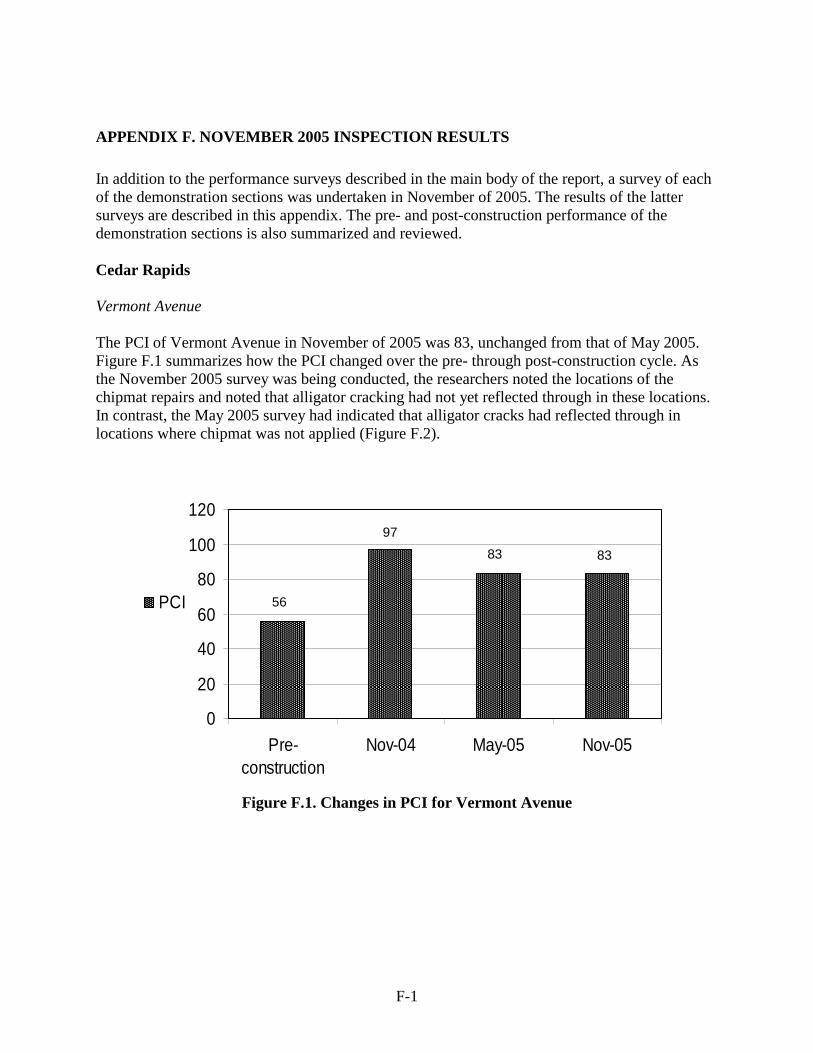
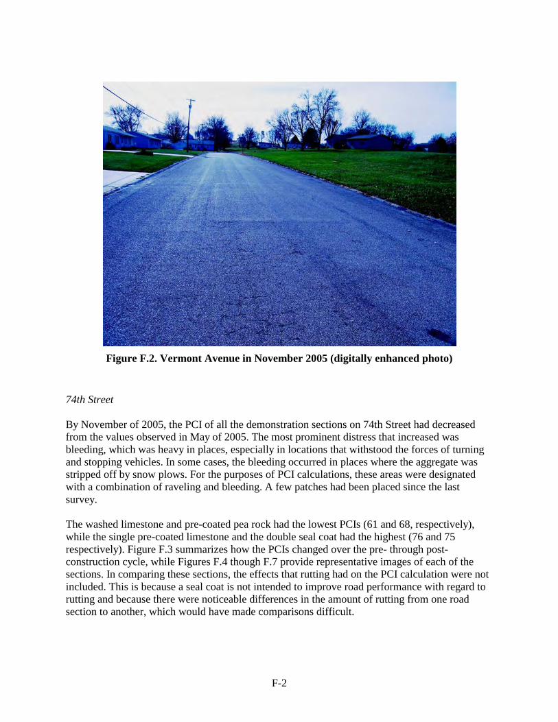
1986) D-2Figure D3 AASHTO flexible pavement design nomograph (Yoder and Witczak 1975) D-3Figure F1 Changes in PCI for Vermont Avenue F-1Figure F2 Vermont Avenue in November 2005 (digitally enhanced photo) F-2Figure F3 Changes in PCI for 74th Street F-3Figure F4 Typical view of pre-coated limestone on 74th Street (digitally enhanced photo) F-3Figure F5 Typical view of washed limestone on 74th Street (digitally enhanced photo)F-4Figure F6 Typical view of pre-coated pea rock on 74th Street (digitally enhanced photo) F-4Figure F7 Typical view of double seal coat on 74th Street (digitally enhanced photo)F-5Figure F8 Changes in PCI for Aspen Drive F-6Figure F9 Changes in PCI for Vine Street and Fourth StreetF-6
LIST OF TABLES
Table 1 PCI condition rating5 Table 2 Decision matrix11 Table 3 Limestone chip gradation (used for both pre-coated and washed chips) 24 Table 4 Gradation of 38-inch pea rock 24 Table 5 Gradation of 12-inch limestone 25 Table 6 Construction summary for Cedar Rapids 74th Street test section 28 Table 7 Council Bluffs pea rock gradation (seal coat cover aggregate) 31 Table 8 Pea rock gradation for Council Bluffs seal coat cover aggregate (mineral aggregate
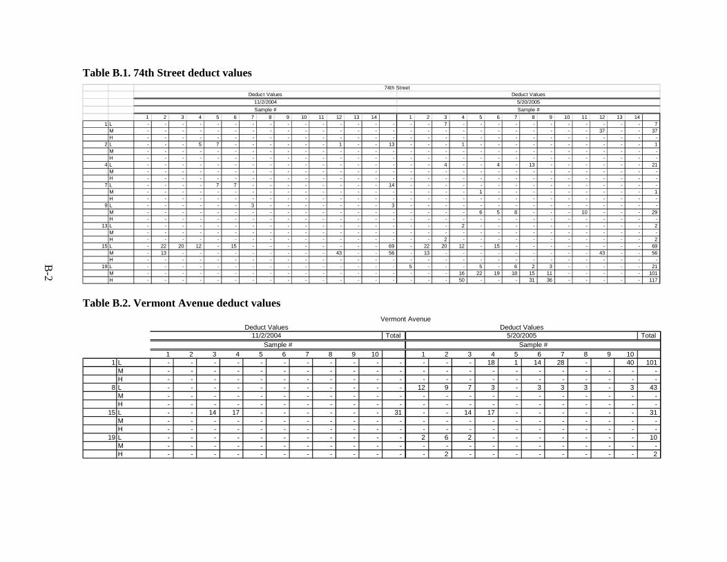
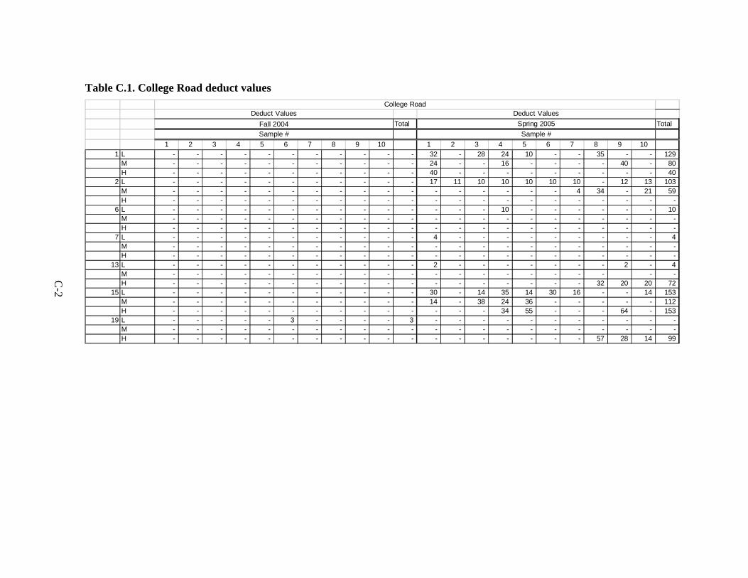
for armor coat) 32 Table 9 Type III micro-surfacing gradations (ISSA method A143) 36 Table 10 Type III micro-surfacing gradations (West Des Moines specifications)36 Table 11 Differences in average loudness (in decibels)55 Table B1 74th Street deduct valuesB-2Table B2 Vermont Avenue deduct values B-2 Table B3 Original estimated deduct values for 74th Street B-3 Table B4 Original estimated deduct values for Vermont Avenue B-3 Table C1 College Road deduct values C-2Table D1 Structural layer coefficents proposed by AASHTO Committee on Design October
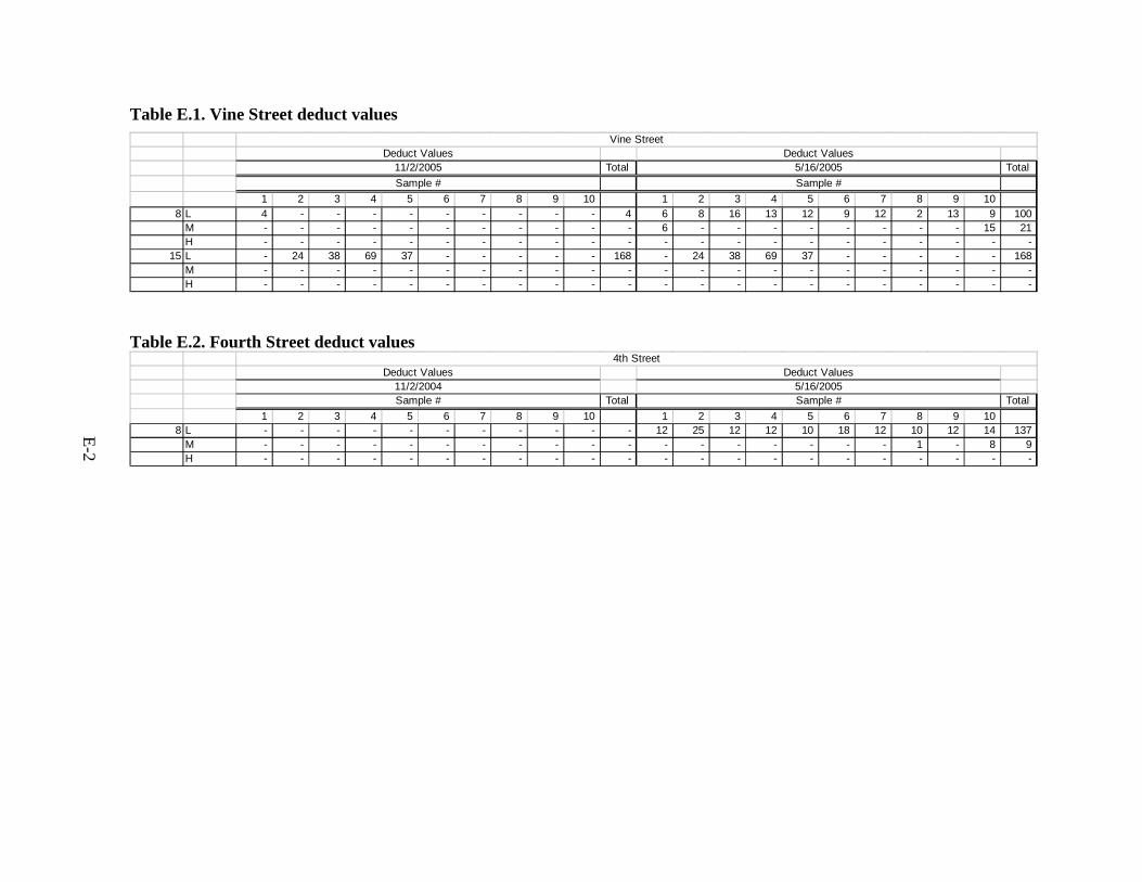
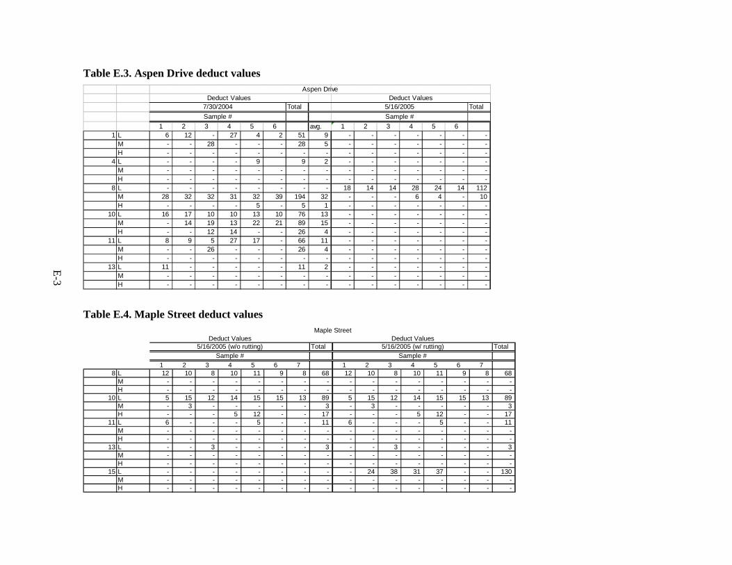
12 1961D-3 Table E1 Vine Street deduct values E-2 Table E2 Fourth Street deduct values E-2 Table E3 Aspen Drive deduct valuesE-3 Table E4 Maple Street deduct valuesE-3 Table G1 Fourth Street sound levels for micro-surfacing and asphalt surfaces G-1 Table G2 Bulk sample results of micro-surfacing and asphalt surface sound levels G-2
viii
ACKNOWLEDGEMENTS
This project was funded by the Iowa Highway Research Board as Project TR-507 The technical review panel included
bull Jeff Nash PE City of West Des Moines bull Jeff Krist PE City of Council Bluffs bull Denny Clift City of Cedar Rapids bull Greg Parker PE Johnson County Engineer bull David Paulson PE Carroll County Engineer
Sta-Built Construction of Harlan Iowa and municipal staff members from the City of Cedar Rapids the City of West Des Moines and the City of Council Bluffs participated in the construction of test sections This support is gratefully acknowledged
ix
EXECUTIVE SUMMARY
When thin maintenance surfaces are properly applied they can economically extend the life of a road enhance appearances and improve the road usersrsquo driving experience Thin maintenance surfaces include fog seals seal coats slurry seals and micro-surfacing Thin hot mix overlays are closely related maintenance treatments All these treatments waterproof and restore the pavement surface Some can also fill ruts and depressions but none significantly add to the structure of the pavement Previous phases of this study investigated the use of thin maintenance surfaces on primary and secondary roads in rural areas of Iowa (Jahren et al 1999 and 2003) This phase of the project focuses on the use of thin maintenance surfaces in municipalities
The objectives of this report are as follows
bull Update previously conducted literature reviews on the topic bull Demonstrate and compare the use of thin maintenance surfaces for municipalities in a
series of test sections bull Revise the treatment selection matrix based on the findings of this investigation
A handbook for the use of thin maintenance surface treatments will be provided in a separate forthcoming document
Test sections were constructed in five locations in three Iowa cities Cedar Rapids Council Bluffs and West Des Moines
Cedar RapidsmdashTwo comparisons took place (1) a demonstration of chipmat (geotechnical fabricndashreinforced seal coat) over alligator cracked but stable pavement included a comparison between areas with chipmat and areas without chipmat and (2) a comparison of four seal coat cover aggregates using high-float emulsion binder HFE-90
bull 38-inuncoated limestone chip single seal coat bull 38-in pre-coated limestone chips single seal coat bull 38-in precoated pearock single seal coat bull 12-in uncoated limestone and 38-in pre-coated limestone chip double seal coat
Council BluffsmdashDemonstration of seal coating on an unbound stabilized road with 38-in pearock and CRS 2P binder
West Des MoinesmdashComparison between Type III micro-surfacing with quartzite versus limestone aggregate
xi
The test section locations and treatment types were selected in consultation with the municipal engineers in their respective locations and applied by in-house crews or by contract through the municipality The test sections were rated for distresses before and after application of the treatments according the method described by Shahin (1994) and summarized as a pavement condition index (PCI)
The following conclusions were drawn
bull Pre-coated limestone chips and high-float emulsion provided a robust treatment that performed well despite shortcomings in the construction process has good public acceptance and generates low amounts of fugitive dust
bull Chipmat is a promising maintenance treatment for low-volume roads with relatively stable alligator cracks
bull Type III limestone micro-surfacing aggregate appears to be a promising alternative to quartzite aggregate The modified gradation used for this investigation produced micro-surfacing with a tighter surface that suffered less snowplow damage in comparison to the surface that was investigated (from 1999) in Jahren et al (2003)
bull The exterior noise produced by vehicles trafficking new micro-surfacing was higher in comparison to a smooth hot mix surface However the noise level was reduced as the micro-surfacing aged and the surface became smoother and tighter under traffic
bull Proper treatment selection good construction techniques and careful planning are necessary for good results in applying thin maintenance surfaces
It is recommended that highway and road officials (1) consider selecting robust maintenance treatments in order to enhance chances for success (2) maintain good quality control and schedule control in applying treatments and (3) consider the use of limestone for micro-surfacing aggregate
More testing is recommended for chip mat and limestone aggregate micro-surfacing
xii
INTRODUCTION
Rationale
Cities across America are continually facing budget cuts from decreased revenues
In the National League of Citiesrsquo latest annual survey of city finance directors more than three in five respondents (63) said their cities were less able to meet financial needs during 2004 than in the previous year Looking ahead 61 percent say they expect their cities to be less able to meet their 2005 needs relative to the current fiscal year (Pagano 2004)
As a result of decreased revenues city officials are forced to cut budgets and streamline services provided Major sectors requiring large amounts of city budgets are municipal public works departments These departments are responsible for facilities such as streets sewers water works electricity cemeteries and parks maintenance Although a city cannot radically reduce public works funding for obvious reasons funding may not be adequate to meet current needs or effectively increased to support growth
To compound the problem of budget shortfalls public works officials must also deal with aging public works systemsmdashspecifically streets As these streets age street officials must deal with rehabilitating and reconstructing these pavements to maintain safety and a comfortable ride The cost of maintenance rehabilitation and reconstruction of these streets is increasing When budgets are fixed the amount of work the public works department can perform each season is reduced This lack of resources and attention causes other streets and facilities to degrade
Cost-effective methods of extending pavement service life must be developed or the overall condition of street systems will continue to fall By extending the life of a pavement public officials are able to spread out the workload and decrease the amount of rehabilitation and reconstruction necessary to maintain the system in good condition
However in cities many public officials who are responsible for streets are also responsible for cemeteries sewer systems and city mowing These additional responsibilities reduce the amount of time that could be used to investigate and test different techniques to determine effective pavement maintenance strategies Currently many street officials have limited awareness of and experience with the wide variety of maintenance techniques that are available
Some public works directors and street superintendents utilize preventive maintenance strategies to address the deterioration of their aging streets The American Association of State and Highway Transportation Officials (AASHTO) defines preventive maintenance as ldquothe planned strategy of cost-effective treatments to an existing roadway system and its
1
appurtenances that preserves the system retards future deterioration and maintains or improves the functional condition of the system (without substantially increasing structural capacity)rdquo (1986) Many types of preventive maintenance techniques have been developed to maintain and extend the service life of a street Each of these surfaces and techniques can effectively mitigate or prevent distresses such as cracking and raveling that shorten a pavementrsquos service life However many of the techniques that work well with certain types of pavements and distresses are not necessarily effective on others
Thin maintenance surfaces (TMSs) are a set of cost-effective preventive maintenance surfacing techniques that can be used to extend the life of bituminous pavementmdashpavement built with hot mix asphalt hot mix asphalt overlays of portland cement concrete pavements built-up seal coat (chip seal) stabilized materials or a combination of these These thin maintenance surfaces do not serve to increase the strength or structure of a road but rather to mitigate existing distresses and prevent future distresses that shorten a pavementrsquos service life TMSs include surfacing techniques such as seal coats slurry seals micro-surfacing fog seals and smooth seals A municipality can both address the issues that cause early deterioration and simultaneously extend pavement life by using thin maintenance surfaces When pavement life is extended funding does not have to be invested in rehabilitation and rebuilding as often allowing more funding to be invested in each cycle with better results
Extensive research and numerous studies have been performed to improve and evaluate the effectiveness of these various TMSs These studies include the Long Term Pavement Performance (LTPP) SPS-3 test sections conducted by the State Highway Research Program (SHRP) which constructed 81 test sites that used various thin maintenance surfaces (Galehouse et al 2005 Hanna 1994) and the two previous phases of research performed at Iowa State University which involved construction of test sections on four US highways (Jahren et al 1999 Jahren et al 2003) Many other states such as Alaska (McHattie and Elieff 2001) Colorado (Outcalt 2001) and Minnesota (Geib and Wood 2001) have conducted their own studies of TMSs These studies and others have focused on developing new design techniques for each surface determining what distresses are mitigated determining ideal application times defining best practices for construction (Gransberg and James 2005) developing decision matrices for determining which surface to apply (Hicks and Peshkin 2000) and analyzing life cycle costs of the maintenance techniques
The previously referenced studies also encourage public officials to develop pavement management programs and overhaul existing programs to incorporate preventive maintenance and TMSs However many of these studies are lengthy and do not provide street and road officials with easy access to relevant material if officials must struggle to learn about and test new techniques the chances of adopting a new program are small Additionally although these studies may provide useful information many public officials prefer to see the surface for themselves or discuss the effectiveness of these techniques with colleagues who have had actual experience Furthermore some elements of these programs need to be modified to meet the needs of smaller communities
2
Research Objectives
Previous phases of TMS research have provided information about the uses of thin maintenance surfaces in rural settings and a decision matrix for selecting appropriate TMS strategies Although this information is somewhat applicable to an urban setting urban areas have different road maintenance challenges that should be considered separately This research project will provide street officials with suggestions for thin maintenance surface techniques that street departments can easily test and include into their current programs
This research project facilitated the construction of five test sections in three municipalities using TMSs in urban settings Test section sites and surfaces were selected to suit the needs of municipalities and were applied to roads with an array of various distresses and maintenance needs The test sections were constructed and the performance observed for a period of one year
During construction of the test sections successes hindrances and lessons learned were documented for inclusion in this report and other technology transfer activities
Study Methodology
City street engineers who expressed interest in this project were asked to serve on the technical advisory committee and recommend streets in their respective cities to become candidate test sections The following individuals comprised the advisory committee
bull Jeff Nash PE City of West Des Moines bull Jeff Krist PE City of Council Bluffs bull Denny Clift City of Cedar Rapids bull Greg Parker PE Johnson County Engineer bull David Paulson PE Carroll County Engineer
The labor equipment and materials for test section construction were to be supplied by the sponsoring city In each case test section construction addressed a current maintenance need for each of the sponsoring cities The criteria defined by the researchers for the test sections were as follows
bull Street needed to be located in an urban setting bull Existing surface needed to be bituminous bull Situation needed to be similar to situations that officials in other cities were
experiencing
Moreover each city was asked to outline its current street maintenance program This included brief descriptions of current maintenance practices and previous experiences with
3
TMSs Researchers needed to become familiar with the needs of the city as well as the level of funding available for the test sections
Each city provided three to six streets of varying ages locations traffic loads and pavement conditions The researchers toured the designated roads and made final selections Consideration was given to the pavement type types of distress present density of the distresses and the traffic volume The researchers also wanted to test some pavements with higher traffic volumes so efforts were made to include at least some streets with higher average daily traffic (ADT) densities If the test section had distresses that indicated structural failure of the pavement the pavement was considered for a stopgap procedure A stopgap procedure is a procedure that is intended to extend the life of a pavement for a few years before a more expensive rehabilitation or reconstruction project can take place Because TMSs are not effective at mitigating or preventing structural-related distresses researchers recommended that base stabilization or full-depth patching be performed in problem areas before application of a new surface The test sections selected were three in West Des Moines two in Cedar Rapids and one in Council Bluffs
Discussions between the city engineers and researchers aided the process of selecting test sections Researchers interviewed the city engineers collecting further details on each test section in order to determine the goals for each effort A number of TMSs were suggested for each pavement that was a likely candidate The advantages and disadvantages of each surface were discussed for each street These discussions involved several topics ranging from construction limitations to material availability and funding concerns In some cases city engineers were uncertain whether the materials for certain TMSs could be acquired These discussions required a number of weeks to complete in order to ensure that all concerns could be identified and uncertainties addressed
After the final TMS selection for each test section researchers finished investigating how the surface would be constructed what materials were available and which materials were the best to use Past experiences and information gleaned from the literature were considered in making decisions Material suppliers and contractors were contacted
Condition surveys of each of the test sections were performed before construction after construction and after the first winter These condition surveys recorded the amount and severity of existing distresses and a pavement condition index was calculated The condition survey procedure is described in the following section Digital photo logs were taken of the test sections before during and after construction
A description of the construction process for of each test section is included in subsequent sections
4
Pavement Condition Survey Procedure
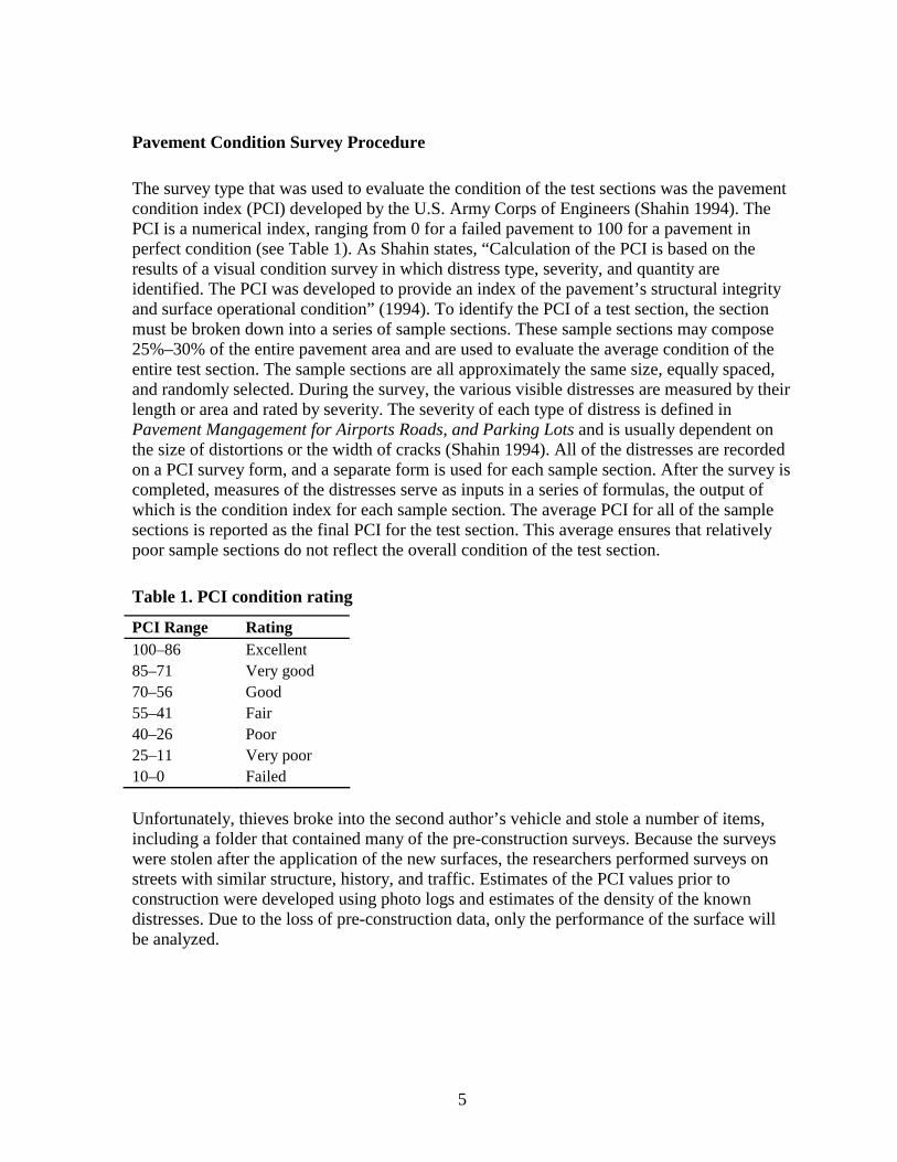
The survey type that was used to evaluate the condition of the test sections was the pavement condition index (PCI) developed by the US Army Corps of Engineers (Shahin 1994) The PCI is a numerical index ranging from 0 for a failed pavement to 100 for a pavement in perfect condition (see Table 1) As Shahin states ldquoCalculation of the PCI is based on the results of a visual condition survey in which distress type severity and quantity are identified The PCI was developed to provide an index of the pavementrsquos structural integrity and surface operational conditionrdquo (1994) To identify the PCI of a test section the section must be broken down into a series of sample sections These sample sections may compose 25ndash30 of the entire pavement area and are used to evaluate the average condition of the entire test section The sample sections are all approximately the same size equally spaced and randomly selected During the survey the various visible distresses are measured by their length or area and rated by severity The severity of each type of distress is defined in Pavement Mangagement for Airports Roads and Parking Lots and is usually dependent on the size of distortions or the width of cracks (Shahin 1994) All of the distresses are recorded on a PCI survey form and a separate form is used for each sample section After the survey is completed measures of the distresses serve as inputs in a series of formulas the output of which is the condition index for each sample section The average PCI for all of the sample sections is reported as the final PCI for the test section This average ensures that relatively poor sample sections do not reflect the overall condition of the test section
Table 1 PCI condition rating
PCI Range Rating 100ndash86 Excellent 85ndash71 Very good 70ndash56 Good 55ndash41 Fair 40ndash26 Poor 25ndash11 Very poor 10ndash0 Failed
Unfortunately thieves broke into the second authorrsquos vehicle and stole a number of items including a folder that contained many of the pre-construction surveys Because the surveys were stolen after the application of the new surfaces the researchers performed surveys on streets with similar structure history and traffic Estimates of the PCI values prior to construction were developed using photo logs and estimates of the density of the known distresses Due to the loss of pre-construction data only the performance of the surface will be analyzed
5
THIN MAINTENANCE SURFACES
Thin maintenance surfaces are thin applications of an asphalt binder and aggregate that is applied to an existing bituminous pavement These surfaces are not intended to add any structure but serve as a waterproof seal and a new wearing course These surfaces can be used to extend the life of a pavement by preventing future distress or mitigating current distress
There are three types of an asphalt binder that can be chosen for a TMS The three options are a hot asphalt binder an emulsion and a cutback A hot asphalt binder is merely an asphalt binder that has been heated to 300degF so that it has reached its melting point and has become liquid and sufficiently non-viscous to allow application by spraying After the hot asphalt binder is applied and the temperature of the binder drops it becomes viscous and hardens An emulsion is a mixture of asphalt binder water and an emulsifier An emulsion can be heated to 150 ordmF to 185ordmF (65 ordmC to 85ordmC) and can then be applied at ambient summertime temperatures (Iowa DOT 2006) After an emulsion is applied to a pavement the water evaporates and leaves the asphalt binder (called residue) behind A cutback is a mixture of an asphalt binder and a petroleum solvent usually kerosene or fuel oil When a cutback is applied to a pavement the solvent evaporates leaving the asphalt binder behind
The aggregate that is selected for a TMS is typically that which is locally available The common aggregates that are used in Iowa are limestone quartzite and pea rock One of the main considerations when selecting the aggregate for a TMS is the aggregate gradation Depending on the TMS the proper aggregate gradations can vary greatly from a dense gradation (for slurry seal or micro-surfacing) to a single-size gradation (for certain seal coat or chip seal applications)
Seal Coat (Chip Seal)
A seal coat is an application of a bituminous binder followed by an application of single-sized aggregate chips Although ldquoseal coatrdquo is the most common terminology for this procedure in Iowa the same procedure is often called ldquochip sealrdquo elsewhere Seal coats can be used on bituminous surfaces (such as hot mix asphalt pavements) and for further maintenance and sealing of built-up seal coat With proper operation it may be used to provide a bound surface for unpaved roads such as gravel or crushed rock roads Seal coats can be used as (1) a preventive maintenance treatment on hot mix asphalt (2) another layer for a road surfaced with many layers of built-up seal coat or (3) as a stopgap holding treatment to extend the life of a severely distressed pavement a short amount of time until rehabilitation or reconstruction can take place However if seal coat is used as a stopgap for severely distressed pavement the amount of time it can be expected to extend the life of the pavement is considerably less than the amount of life extension that would result from using seal coat as a preventive maintenance treatment on lightly distressed pavement
6
Seal coats are useful in waterproofing the surface and sealing existing cracks in the pavement They also provide a new wearing course and add friction for traction Some disadvantages of a seal coast include that it may have the appearance of a gravel road to some road users and neighboring property owners and there is a possibility for dust and flyrock both of which may be annoyances to vehicle and property owners Also seal coats add no structure to a pavement and cannot be used to fill in ruts
Traffic can be allowed on a seal coat after the aggregate has been seated by a pneumatic tire roller However the speed should be controlled (possibly by a pilot car) so that the top vehicle speed does not exceed 25 mph Seal coats are also very cost effective with an average price of $080yd2 (based on anecdotal evidence from first author in 2005)
Variations on a typical seal coat include a double seal coat cape seal sandwich seal and racked-in seal A double seal coat is the double application of a single chip seal The nominal aggregate dimension used for the first layer of the seal coat is typically one and a half to two times the dimension of the second layer of aggregate A double seal coat provides more waterproofing and is more robust than a single seal coat A cape seal is single seal coat followed by the application of a slurry seal (Slurry seal will be discussed in more detail later) A sandwich seal is an application of aggregate followed by the application of the binder and topped off with another layer of smaller aggregate A racked-in seal is a single seal coat followed by an application of sand to fill voids
In Iowa seal coats are typically used on low-volume roads (lt 2000 vehicles per day) such as residential streets and lower volume secondary and primary roads In other locations particularly some western states they are used on higher traffic roads as well
Construction of a seal coat requires the following steps
bull Set up traffic control bull Sweep the pavement removing any debris such as sand rocks salt or dirt bull Spray the pavement with an emulsion cutback or hot asphalt binder with a
distributor truck Specified application rates are 035 to 035 galyd2 (11 to 16 lm2 ) for 12-in cover aggregate and 025 to 035 galyd2 (16 to 20 lm2) for 38-in cover aggregate (Iowa DOT 2006) In previous research application rates ranged from 022 to 032 galyd2 after a material application rate design was executed (Jahren et al 2003) This was less than the standard practice in Iowa
bull Spread a single layer of chips over the binder with a chip spreader A specified application rate is 30 lbyd2 (16 kgm2) (Iowa DOT 2006) Reports from construction projects indicate that this spread rate results in extra aggregate that must be swept from the road and that 25 lbyd2 (14 kgm2 ) often provides better results In previous research application rates ranged from 19 to 22 lbyd2 after a material application rate design was executed (Jahren et al 2003)
bull Immediately seat the aggregate in the binder by following the chip spreader with a pneumatic tire roller The roller should make several passes to adequately seat the
7
aggregate If one roller cannot keep up with the operation additional rollers should be added to the fleet
bull Allow the binder to cure and then sweep off any unbound aggregate
Chipmat
Chipmat is a thin maintenance technique that is new to Iowa It is a single seal coat placed over geotechnical fabric The geotechnical fabric is used to bridge over existing cracks in order to mitigate the reflections of cracks to the new surface The binder-soaked fabric also provides an extra layer of waterproofing and resists water entrance in the subbase an already weakened area A chipmat process using hot asphalt binder has been developed and successfully used in the hot arid regions of southern California (Davis 2003) However hot asphalt is not commonly used in Iowa Since emulsion is more commonly available in Iowa the following construction process was developed specifically for use with emulsion as part of this research project
bull Set up traffic control bull Sweep the pavement Blow out the cracks with an air compressor bull Apply the tack coat with the distributor truck bull Roll the fabric over the binder bull Spread sand over the fabric and any exposed binder If the fabric will not be covered
by the seal coat for a number of days more sand should be used to protect the fabric from traffic
bull Seat the fabric in the binder using a pneumatic tire roller Sweep the sand off of the fabric
bull Wait several days for the emulsion to cure completely and for water to evaporate from the tack coat that is holding the geotechnical fabric
bull Sweep sand from the geotechnical fabric bull Place the standard seal coat
When placed correctly on alligator cracks that do not pump under traffic the chipmat is effective for limiting the extent to which these cracks reflect through to the new seal coat One of the disadvantages of the chipmat is that if the agency ever desires to mill the road using a milling machine the fabric can get tangled in the teeth of the milling drum Specifications and a guide for the fabric have been developed by the Asphalt Interlayer Association (AIA) and can be downloaded at httpwwwaia-usorg
Slurry Seal
A slurry seal is a mixture of emulsion well-graded aggregate mineral filler (typically cement) and water The ingredients are mixed before placement and after application the mixture cures into a hard wearing surface The slurry has a consistency of wet mud and can be easily shaped with hand tools
8
The advantages of a slurry seal are that it provides water resistance seals micro-cracks (small cracks that have not propagated through the entire pavement layer) and provides a new wearing surface with more friction and a black appearance similar to that of hot mix asphalt (HMA) Slurry seal also has sufficient stability to fill ruts With careful mix design and application anecdotal evidence indicates that slurry seal has been successfully use to fill ruts in Iowa up to one inch deep Compared to seal coat slurry seals have fewer problems with flyrock and dust and they cure to a darker color which in many cases is more satisfactory to road users and neighboring property owners One disadvantage of a slurry seal is that after it cures it becomes brittle Because the surface is brittle when the underlying pavement moves cracks are reflected very quickly Another disadvantage of slurry seals is that the road must be closed for approximately 6 hours after application in order for the binder to properly cure Once the binder has properly cured traffic can be allowed on the surface without traffic control
Slurry seals are also cost-effective solutions The average price was $090ndash$110yd2 in Iowa in 2005 based on anecdotal evidence from the first author and interviews with city engineers Construction of a slurry seal involves sweeping the surface removing vegetation from cracks and applying the slurry with a machine
Micro-surfacing
Micro-surfacing is a slurry seal that uses 100 crushed aggregate and polymer-modified emulsion Micro-surfacing is also very brittle like slurry seals however because of the added polymers micro-surfacing is more robust and the cracks do not spall and widen as quickly as they do in slurry seals Compared to slurry seal micro-surfacing is more stable and therefore can be more effective at filling ruts in more extreme situations Another advantage of micro-surfacing over slurry seal is that it can be trafficked within one hour of application The main disadvantage of micro-surfacing compared to other TMS is the higher cost Also there is less working time which makes this technique less forgiving if hand work is necessary
The average price of micro-surfacing was approximately $150yd2 in Iowa in 2005 based anecdotal evidence from the author The micro-surfacing application process is similar to that of slurry seal
Fog Seal
A fog seal is a light application of binder to a pavement which serves to seal the surface restore volatile components the surface binder and slow or reverse the effects of oxidation (hardening of surface asphalt) Fog seals should only be used on pavements that are in good condition and serve only to prevent distresses such as oxidation and raveling If necessary a light coating of sand should be spread over the fog seal to provide sufficient friction The binder used in fog seal can be asphalt emulsion gilsonite or a mixture of asphalt and other chemicals known as rejuvenators that are intended to improve the properties of the asphalt surface
9
Some advantages of a fog seal are the low cost ease of construction and black appearance Some disadvantages include the fact that a road with a new fog seal cannot be trafficked until the binder has cured which can take up to 6ndash8 hours depending on weather conditions Also fog seals may have low friction numbers until the binder wears off from the surface of the aggregate that engages tires
The average cost of a fog seal is $018ndash$080yd2 The cost increases if rejuvenators have been added to the emulsion Rejuvenators help to soften oxidized asphalt on the surface of the pavement Construction involves sweeping the surface applying the diluted emulsion and spreading the sand
Thin HMA Overlays Smooth Seal and Other Thin Overlays
Thin HMA overlays are typically less than two inches thick and are applied in manner that is similar to that of a regular HMA overlay HMA has the stability to fill ruts dips and depressions and it provides a smooth quiet surface Although design assumptions are that thin overlays do not add structure to the pavement in actuality they do add a marginal amount of structure and that can be helpful in extending the life of the pavement
A smooth seal a trade name coined by Heartland Asphalt of Mason City IA is a one- to two-inch HMA overlay on an existing seal coat road that is in good condition with little to no structural distress A smooth seal should be applied over low-volume roads with small amounts of truck traffic If regular truck traffic is present the thickness of the overlay should be increased to two inches or more Advantages of the smooth seal include a smooth black pavement long life and elimination of the need for seal coat at short intervals Typically for a pavement made from built-up seal coat it is necessary to apply a new seal coat every one to three years to prevent water from reaching the subbase through newly formed cracks However if a smooth seal is applied it is no longer necessary to apply seal coats unless the purpose is for preventive maintenance of the asphalt pavement These maintenance seal coats can last from five to seven years Smooth seals have performed very well with overlays having a life of 12 years with little to no distress This good performance can be attributed to the fact that the seal coat pavements that they covered provided excellent bases
Cost of a smooth seal is dependent on the local cost for HMA Before application of the smooth seal any structural distress should be repaired with full-depth asphalt patches to prevent the distress from reflecting through on the overlay The application of the smooth seal is the same as the application of any asphalt overlay
Another thin overlay is NovaChipreg which is a proprietary process developed by Koch Pavement Solutions NovaChipreg is a thin lift overlay that uses a coarse-graded aggregate The overlay is placed over a special membrane called NovaBondreg NovaBondreg an emulsion which according to product literature provides a superior bond between the existing pavement and the overlay and also provides a water-resistant membrane Advantages of NovaChipreg include (1) quick application because only one piece of equipment is
10
necessary for application and (2) good drainage and skid resistance due to the coarse-graded aggregate Based on an interview with Koch Pavement Solutions in 2004 the average cost of NovaChipreg is $350yd2 (Matteson)
Decision Matrix for TMSs
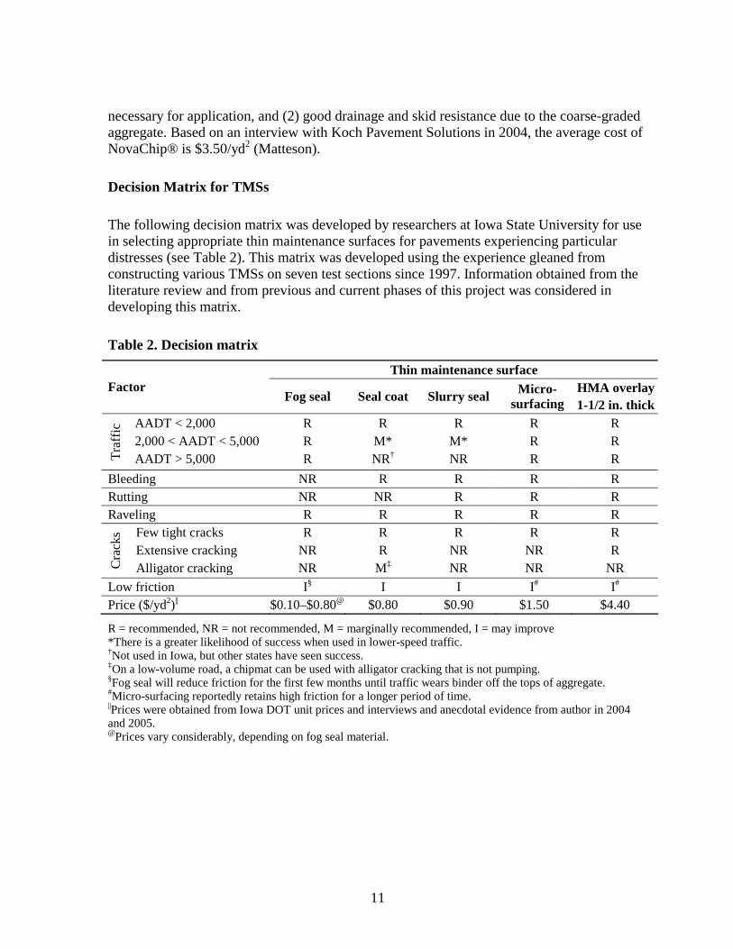
The following decision matrix was developed by researchers at Iowa State University for use in selecting appropriate thin maintenance surfaces for pavements experiencing particular distresses (see Table 2) This matrix was developed using the experience gleaned from constructing various TMSs on seven test sections since 1997 Information obtained from the literature review and from previous and current phases of this project was considered in developing this matrix
Table 2 Decision matrix
Thin maintenance surface Factor Micro- HMA overlay
Fog seal Seal coat Slurry seal surfacing 1-12 in thick
Tra
ffic
AADT lt 2000 R R R R R 2000 lt AADT lt 5000 R M M R R AADT gt 5000 R NRdagger NR R R
Bleeding Rutting
NR NR
R NR
R R
R R
R R
Raveling R R R R R Few tight cracks R R R R R
Cra
cks
Extensive cracking NR R NR NR R Alligator cracking NR MDagger NR NR NR
Low friction Isect I I I I
Price ($yd2)|| $010ndash$080 $080 $090 $150 $440
R = recommended NR = not recommended M = marginally recommended I = may improve There is a greater likelihood of success when used in lower-speed traffic daggerNot used in Iowa but other states have seen success DaggerOn a low-volume road a chipmat can be used with alligator cracking that is not pumpingsectFog seal will reduce friction for the first few months until traffic wears binder off the tops of aggregate Micro-surfacing reportedly retains high friction for a longer period of time ||Prices were obtained from Iowa DOT unit prices and interviews and anecdotal evidence from author in 2004 and 2005 Prices vary considerably depending on fog seal material
11
LITERATURE REVIEW
This section provides a summary review of literature written on thin maintenance surfaces since 2000 A complete version of this review is provided by Plymesser (2005) Previous literature was reviewed in reports for previous phases of this research (Jahren et al 1999 and 2003) This review covers the following seal coats chipmats fog seals slurry seals micro-surfacing thin HMA overlays and any studies that have tested these surfaces
Seal Coating
A seal coat is an application of an asphalt binder onto a bituminous pavement followed by a single layer of aggregate In a report analyzing the effectiveness of seal coats in America researchers found that states which regarded their seal coat programs as excellent used seal coats as a preventive maintenance measure These states had set a cycle for applying the seal coat to a pavement at specific times and in specific intervals These agencies use a five-year cycle and expect a six-year service life from the chip seal (Gransberg and James 2005)
The success of a seal coat is based largely on the timing of the application with respect to the life of the pavement or in the words of AASHTO ldquoplacing the right treatment on the right road at the right timerdquo (1986) Research has quantitatively shown that when seal coats are used on pavements in good condition the initial increase in pavement condition is small but the reduction in pavement deterioration is high (Labi and Sinha 2004) Likewise if the initial increase in pavement condition is high the reduction in pavement deterioration is low For example if a seal coat was placed on a new pavement with low-severity cracks the initial increase in the pavementrsquos condition would be relatively low but the life of the pavement would be extended because the surface and cracks would be sealed from water damage However if a seal coat was placed on a pavement in poor to fair condition the initial increase in the pavement condition would be high because the existing distresses would be sealed and covered but because the pavement has already been distressed no value other than a waterproof membrane was added to the pavement In that scenario failure has already occurred and distress will reflect through to the new surface quickly
Research and common experience has shown that the use of polymer-modified emulsions for chip sealing increases the effectiveness of the seal coat Although the cost of a polymer-modified emulsion is greater many agencies choose to use it because it retains chips better than regular bindersmdashespecially under heavy traffic Polymer-modified binders also prevent bleeding and have more resilience against cracking and crack spalling The international scan team found that each country visited vigorously promoted and used polymer-modified emulsions for seal coats so the team strongly encouraged all agencies to adopt the use of polymer-modified emulsions (Beatty et al 2002 Gransberg and James 2005)
When placing a seal coat it is necessary to use rollers to embed the aggregate into the binder and assure chip retention Rolling should be performed immediately after the chips have been
12
placed on the binder When placing a seal coat the distributor truck governs the speed at which the seal coat is placed because no other activities can take place until the binder has been applied Sometimes it is necessary to provide more than one roller in order for the rollers to keep up with the distributor truck and chip spreader Gransberg Karaca and Senadheera (2004) released a paper that provides information on determining the number of passes a roller must make on the seal coat to ensure that the entire seal is rolled This paper also details how to select the number of rollers required based many variables including the speed of the distributor truck width of the seal coat width of the rollers and speed of the rollers (Gransberg Karaca and Senadheera 2004)
Chipmat
The method of seal coating over fabric called chipmat has proved to be effective for reducing the likelihood that existing alligator cracks will reflect through the new seal coat This process is gaining popularity in southern California In 1987 San Diego County constructed a number of test sections on a pavement in the desert The county used seal coats with various binders over sealed cracks and over fabric All of the surface treatments were effective at sealing the surface However the only treatment that eliminated reflective cracking was the chipmat As of 2003 no cracks had reflected through the chipmats constructed in 1987 In 1999 the San Diego County performed a life cycle cost analysis of the three different treatment methods and found that although the cost of placing the fabric increased the initial construction costs the annual cost of the chipmat was far less than the other seal coats using rubberized emulsion or seal coats over sealed cracks (Davis 2003)
Based on 19 years of experience with the method Brown (2003) describes successful construction methods for chipmat The procedure is briefly summarized as follows
1 Fill all cracks that are wider than 14 inch to prevent the fabric from having to span the cracks
2 Spray tack coat binder at a rate of 030 to 040 galyd2 for hot oil (AR4000 or AR8000) or 035 to 045 galyd2 for emulsion
3 Roll geotechnical fabric from a modified tractor Brown recommends 4-ozyd2 nonshywoven needle-punched fabric
4 Immediately roll the fabric with pneumatic rollers to immerse it in the binder 5 If it is necessary to traffic the road between application of the fabric and application of
the seal coat apply a light coating of sand (2 to 4 lbyd2) to reduce tackiness 6 Apply seal coat according to the usual good practice
Like Davis (2003) Brown (2003) reported excellent results in mitigating crack reflection at a reasonable life cycle cost with this method
13
Fog Seal
A fog seal is an application of binder onto the surface of an asphalt pavement The purpose is to seal the surface and to mitigate oxidation
After applying a fog seal to a pavement it is common to spread a light application of blotting sand Because the fog seal can temporarily reduce the friction of the pavement the sand is used to restore texture and increase skid resistance A brief study analyzing the effects of a fog seal product with the trade name GSB-88 has investigated the effect of a gilsonite sealer binder (GSB) fog seal on pavement friction numbers (Hall 2004) Gilsonite is a naturally occurring substance that is mined in Utah and has a high content of nitrogen and resin it is reportedly effective as an asphalt rejuvenator Under the study three test sections were constructed and researchers monitored changes in friction for eight to ten months The study found that after the fog seal was applied friction values dropped by 12 to 27 points This drop in friction number can be dangerous as motorists are not able to stop as quickly because there is little skid resistance However after about five to nine months of traffic the friction numbers were restored to their pre-construction numbers because the seal had worn off of the top of the aggregate The report also commented that the fog seal was effective at filling in the voids between the individual pieces of aggregate (Hall 2004)
A second phase of research on the fog seal is currently testing the ability of the fog seal to waterproof a surface Again one test section was constructed and monitored Researchers were using a falling head permeameter to test the permeability of both the untreated and treated sections Initial results show that the fog seal was effective at sealing the surface (Hall 2004)
Micro-surfacing
Micro-surfacing is a slurry seal that uses a polymer-modified emulsion and other additives that produce a chemical break One main advantage of micro-surfacing is its ability to cure and be trafficked within one hour
Because micro-surfacing is stable after curing it can be effectively used as filler for ruts up to 15 inches deep When deep ruts are filled a special rut box is used that places the micro-surfacing slurry in one rut at a time The rut box places the largest aggregate in the deepest part of the rut to provide the most stability When micro-surfacing is used to fill ruts or other voids it is recommended that multiple lifts be placed The multiple lifts provide structure and also produce a smoother pavement surface with a more uniform appearance (McHattie and Elieff 2001)
From the perspective of Minnesota Department of Transportation (MnDOT) the primary benefits of micro-surfacing are the fast-paced construction and ability to handle traffic on the surface within one hour of placement (Geib and Wood 2001) This MnDOT report
14
concluded that micro-surfacing is effective at filling ruts when a rut box or scratch course is used When micro-surfacing is initially applied the surface is noisier than a conventional asphalt pavement due to the stones in the surface that do not lay flat until after the surface is trafficked The MnDOT performed a noise level study and found that there was very little increase (Geib and Wood 2001)
LTPPSPS-3 Preventive Maintenance Study
In 1987 the Strategic Highway Research Program (SHRP) set up a project to study the cost effectiveness and optimum timing for application of preventive maintenance treatments A number of test sections consisting of seal coats slurry seals thin HMA overlays and crack seals were constructed throughout the country in different regions with different climates and the test sections were constructed on pavements with various subbases These test sections were monitored by Long Term Pavement Performance (LTPP) and designated as SPS-3 Many of the test sections had exceeded their design lives and were still in service in 2004
The seal coat was the best performer on many of the test sections sites in Texas and is recommended as the best choice for high-traffic routes based on the SPS-3 test sections if rutting is not a concern (Chen Lin and Luo 2003) Seal coats were also very effective in reducing longitudinal transverse and fatigue cracking and the seal coat sealed and protected the centerline joints Thin HMA overlays had the lowest roughness and rutting values but were experiencing some structural distresses such as fatigue cracking and potholes Sections that received the slurry seal are performing better than the control sections and the crack sealed sections which shows that the slurry seal is effective at protecting and sealing the surface (Galehouse et al 2005)
Of interesting note was the fact that the TMS in Michiganmdashthe test sections which had the most severe climatemdashwere performing very well This is strong evidence that preventive maintenance techniques are suitable in all climates (Galehouse et al 2005)
15
TEST SECTION DESCRIPTION AND CONSTRUCTION
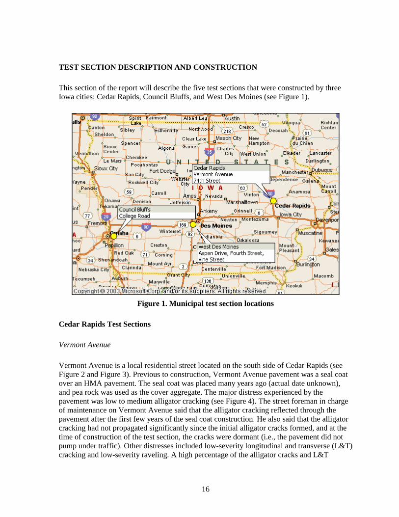
This section of the report will describe the five test sections that were constructed by three Iowa cities Cedar Rapids Council Bluffs and West Des Moines (see Figure 1)
Figure 1 Municipal test section locations
Cedar Rapids Test Sections
Vermont Avenue
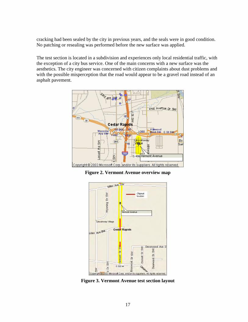
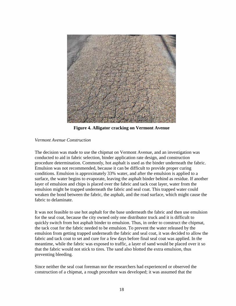
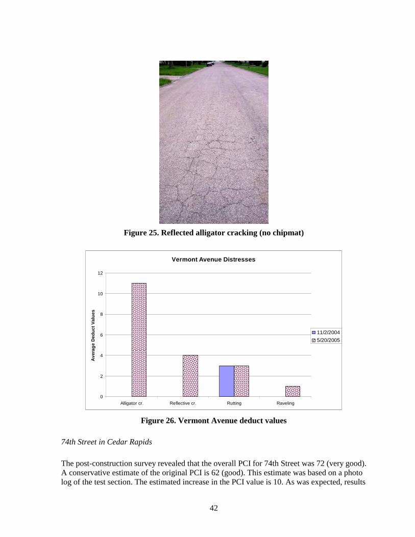
Vermont Avenue is a local residential street located on the south side of Cedar Rapids (see Figure 2 and Figure 3) Previous to construction Vermont Avenue pavement was a seal coat over an HMA pavement The seal coat was placed many years ago (actual date unknown) and pea rock was used as the cover aggregate The major distress experienced by the pavement was low to medium alligator cracking (see Figure 4) The street foreman in charge of maintenance on Vermont Avenue said that the alligator cracking reflected through the pavement after the first few years of the seal coat construction He also said that the alligator cracking had not propagated significantly since the initial alligator cracks formed and at the time of construction of the test section the cracks were dormant (ie the pavement did not pump under traffic) Other distresses included low-severity longitudinal and transverse (LampT) cracking and low-severity raveling A high percentage of the alligator cracks and LampT
16
cracking had been sealed by the city in previous years and the seals were in good condition No patching or resealing was performed before the new surface was applied
The test section is located in a subdivision and experiences only local residential traffic with the exception of a city bus service One of the main concerns with a new surface was the aesthetics The city engineer was concerned with citizen complaints about dust problems and with the possible misperception that the road would appear to be a gravel road instead of an asphalt pavement
Figure 2 Vermont Avenue overview map
Figure 3 Vermont Avenue test section layout
17
Figure 4 Alligator cracking on Vermont Avenue
Vermont Avenue Construction
The decision was made to use the chipmat on Vermont Avenue and an investigation was conducted to aid in fabric selection binder application rate design and construction procedure determination Commonly hot asphalt is used as the binder underneath the fabric Emulsion was not recommended because it can be difficult to provide proper curing conditions Emulsion is approximately 33 water and after the emulsion is applied to a surface the water begins to evaporate leaving the asphalt binder behind as residue If another layer of emulsion and chips is placed over the fabric and tack coat layer water from the emulsion might be trapped underneath the fabric and seal coat This trapped water could weaken the bond between the fabric the asphalt and the road surface which might cause the fabric to delaminate
It was not feasible to use hot asphalt for the base underneath the fabric and then use emulsion for the seal coat because the city owned only one distributor truck and it is difficult to quickly switch from hot asphalt binder to emulsion Thus in order to construct the chipmat the tack coat for the fabric needed to be emulsion To prevent the water released by the emulsion from getting trapped underneath the fabric and seal coat it was decided to allow the fabric and tack coat to set and cure for a few days before final seal coat was applied In the meantime while the fabric was exposed to traffic a layer of sand would be placed over it so that the fabric would not stick to tires The sand also blotted the extra emulsion thus preventing bleeding
Since neither the seal coat foreman nor the researchers had experienced or observed the construction of a chipmat a rough procedure was developed it was assumed that the
18
procedure would take the better part of a day Once on site the foreman and crew discussed the procedure and agreed on a final procedure to be followed A small trial section was constructed in an alley before any fabric was laid on the actual test section The procedure used was as follows
bull Sweep the pavement to remove any large debris bull Use compressed air to blow any sand and debris out of the alligator cracks to be
covered bull Set the distributorrsquos spray bar approximately 1ndash15 feet wider than the fabric This
ensures that the edges of the fabric are completely saturated minimizing the chances that the edges might roll up
bull Apply the emulsion to the pavement The length of the strip should be a few feet longer than the piece of fabric
bull Adjust the application rate based on the amount width and depth of alligator cracking This is because some of the emulsion will seep into the cracks and will not be available to tack the fabric
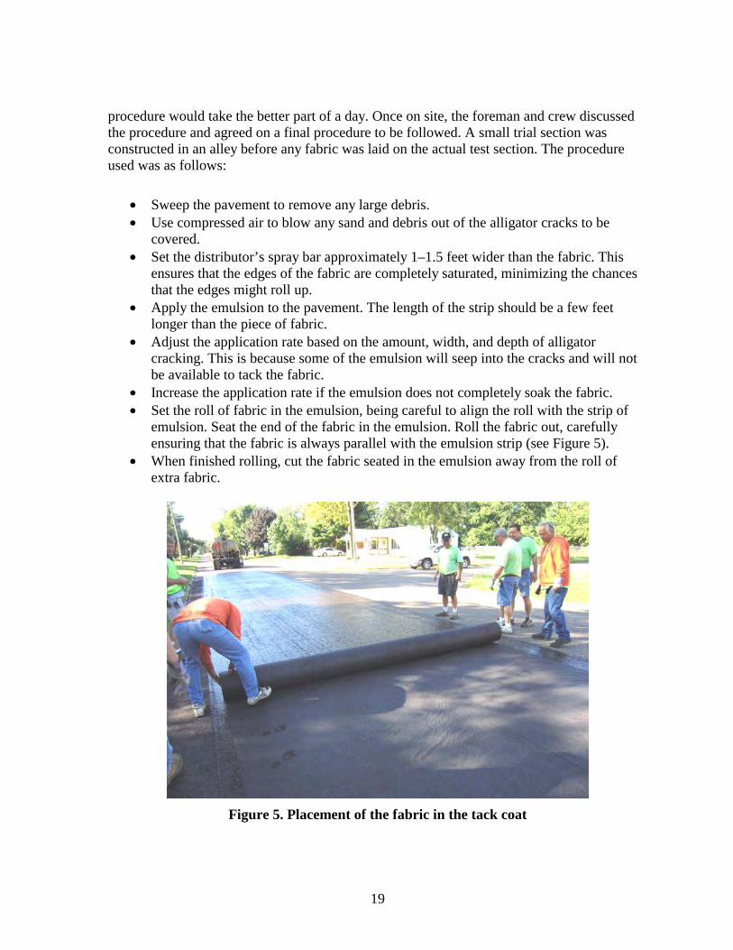
bull Increase the application rate if the emulsion does not completely soak the fabric bull Set the roll of fabric in the emulsion being careful to align the roll with the strip of
emulsion Seat the end of the fabric in the emulsion Roll the fabric out carefully ensuring that the fabric is always parallel with the emulsion strip (see Figure 5)
bull When finished rolling cut the fabric seated in the emulsion away from the roll of extra fabric
Figure 5 Placement of the fabric in the tack coat
19
bull Repair any large wrinkles in the fabric Make a cut down the middle of the wrinkle and overlap the fabric in the direction of traffic If the wrinkle is large cut away any excess fabric
bull Spread approximately 14 inch of sand on top of the fabric with a sand spreader truck Make multiple passes if necessary
bull Make several passes over the fabric and sand using a pneumatic tire roller If any fabric begins to pull up do not attempt to reseat the fabric just cut it away
bull Allow the emulsion and fabric to cure for a few days bull Apply standard seal coat
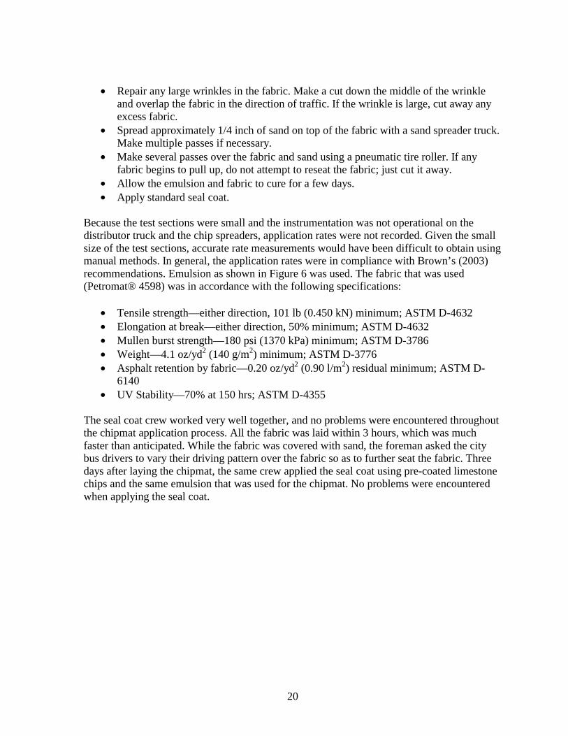
Because the test sections were small and the instrumentation was not operational on the distributor truck and the chip spreaders application rates were not recorded Given the small size of the test sections accurate rate measurements would have been difficult to obtain using manual methods In general the application rates were in compliance with Brownrsquos (2003) recommendations Emulsion as shown in Figure 6 was used The fabric that was used (Petromatreg 4598) was in accordance with the following specifications
bull Tensile strengthmdasheither direction 101 lb (0450 kN) minimum ASTM D-4632 bull Elongation at breakmdasheither direction 50 minimum ASTM D-4632 bull Mullen burst strengthmdash180 psi (1370 kPa) minimum ASTM D-3786 bull Weightmdash41 ozyd2 (140 gm2) minimum ASTM D-3776 bull Asphalt retention by fabricmdash020 ozyd2 (090 lm2) residual minimum ASTM Dshy
6140 bull UV Stabilitymdash70 at 150 hrs ASTM D-4355
The seal coat crew worked very well together and no problems were encountered throughout the chipmat application process All the fabric was laid within 3 hours which was much faster than anticipated While the fabric was covered with sand the foreman asked the city bus drivers to vary their driving pattern over the fabric so as to further seat the fabric Three days after laying the chipmat the same crew applied the seal coat using pre-coated limestone chips and the same emulsion that was used for the chipmat No problems were encountered when applying the seal coat
20
Figure 6 Cedar Rapids emulsion
21
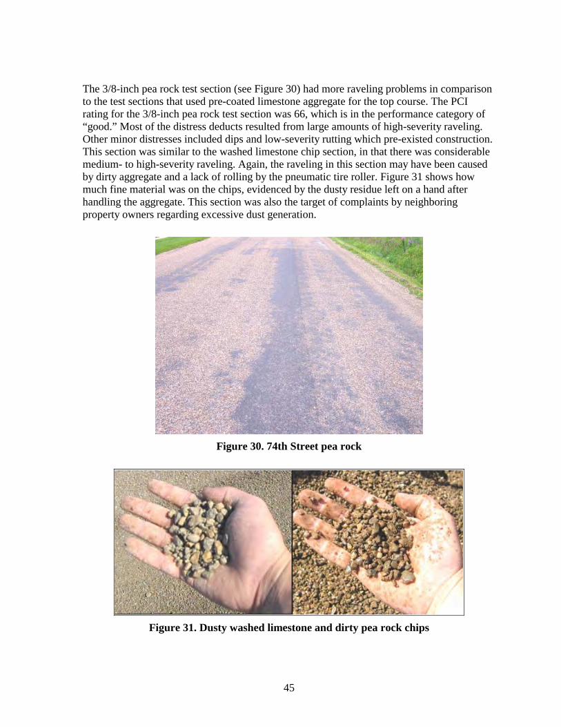
74th Street
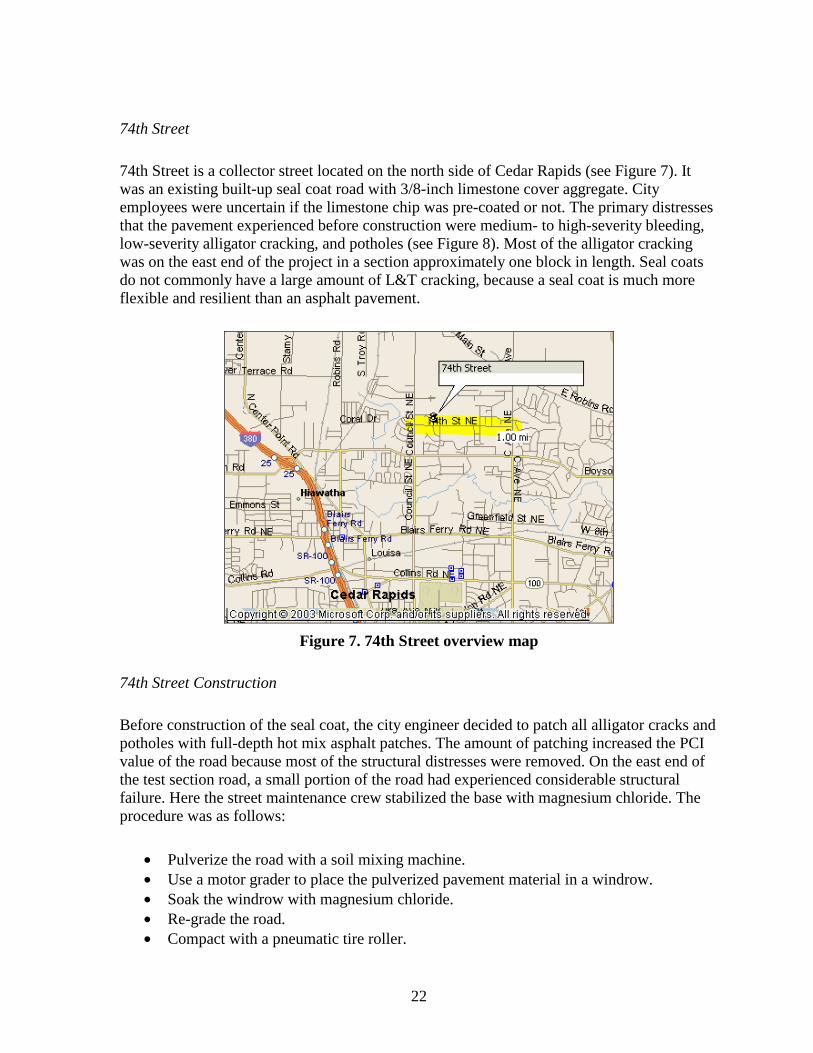
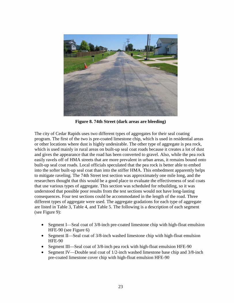
74th Street is a collector street located on the north side of Cedar Rapids (see Figure 7) It was an existing built-up seal coat road with 38-inch limestone cover aggregate City employees were uncertain if the limestone chip was pre-coated or not The primary distresses that the pavement experienced before construction were medium- to high-severity bleeding low-severity alligator cracking and potholes (see Figure 8) Most of the alligator cracking was on the east end of the project in a section approximately one block in length Seal coats do not commonly have a large amount of LampT cracking because a seal coat is much more flexible and resilient than an asphalt pavement
Figure 7 74th Street overview map
74th Street Construction
Before construction of the seal coat the city engineer decided to patch all alligator cracks and potholes with full-depth hot mix asphalt patches The amount of patching increased the PCI value of the road because most of the structural distresses were removed On the east end of the test section road a small portion of the road had experienced considerable structural failure Here the street maintenance crew stabilized the base with magnesium chloride The procedure was as follows
bull Pulverize the road with a soil mixing machine bull Use a motor grader to place the pulverized pavement material in a windrow bull Soak the windrow with magnesium chloride bull Re-grade the road bull Compact with a pneumatic tire roller
22
Figure 8 74th Street (dark areas are bleeding)
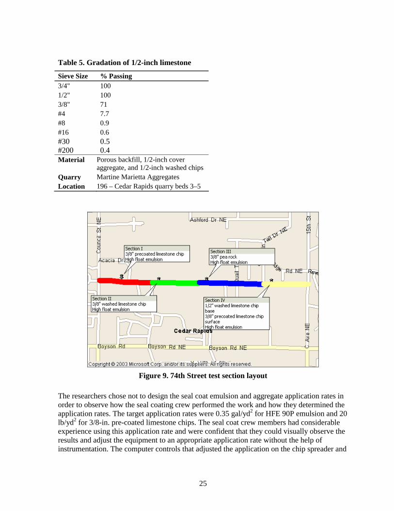
The city of Cedar Rapids uses two different types of aggregates for their seal coating program The first of the two is pre-coated limestone chip which is used in residential areas or other locations where dust is highly undesirable The other type of aggregate is pea rock which is used mainly in rural areas on built-up seal coat roads because it creates a lot of dust and gives the appearance that the road has been converted to gravel Also while the pea rock easily ravels off of HMA streets that are more prevalent in urban areas it remains bound onto built-up seal coat roads Local officials speculated that the pea rock is better able to embed into the softer built-up seal coat than into the stiffer HMA This embedment apparently helps to mitigate raveling The 74th Street test section was approximately one mile long and the researchers thought that this would be a good place to evaluate the effectiveness of seal coats that use various types of aggregate This section was scheduled for rebuilding so it was understood that possible poor results from the test sections would not have long-lasting consequences Four test sections could be accommodated in the length of the road Three different types of aggregate were used The aggregate gradations for each type of aggregate are listed in Table 3 Table 4 and Table 5 The following is a description of each segment (see Figure 9)
bull Segment ImdashSeal coat of 38-inch pre-coated limestone chip with high-float emulsion HFE-90 (see Figure 6)
bull Segment IImdashSeal coat of 38-inch washed limestone chip with high-float emulsion HFE-90
bull Segment IIImdashSeal coat of 38-inch pea rock with high-float emulsion HFE-90 bull Segment IVmdashDouble seal coat of 12-inch washed limestone base chip and 38-inch
pre-coated limestone cover chip with high-float emulsion HFE-90
23
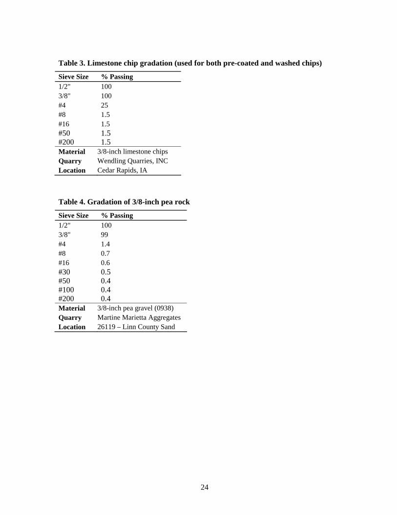
Table 3 Limestone chip gradation (used for both pre-coated and washed chips)
Sieve Size Passing 12 100 38 100 4 25 8 15 16 15 50 15 200 15 Material 38-inch limestone chips Quarry Wendling Quarries INC Location Cedar Rapids IA
Table 4 Gradation of 38-inch pea rock
Sieve Size Passing 12 100 38 99 4 14 8 07 16 06 30 05 50 04 100 04 200 04 Material 38-inch pea gravel (0938) Quarry Martine Marietta Aggregates Location 26119 ndash Linn County Sand
24
Table 5 Gradation of 12-inch limestone
Sieve Size Passing 34 100 12 100 38 71 4 77 8 09 16 06 30 05 200 04 Material Porous backfill 12-inch cover
aggregate and 12-inch washed chips Quarry Martine Marietta Aggregates Location 196 ndash Cedar Rapids quarry beds 3ndash5
Figure 9 74th Street test section layout
The researchers chose not to design the seal coat emulsion and aggregate application rates in order to observe how the seal coating crew performed the work and how they determined the application rates The target application rates were 035 galyd2 for HFE 90P emulsion and 20 lbyd2 for 38-in pre-coated limestone chips The seal coat crew members had considerable experience using this application rate and were confident that they could visually observe the results and adjust the equipment to an appropriate application rate without the help of instrumentation The computer controls that adjusted the application on the chip spreader and
25
distributor were not working properly over the summer so the crew was using this method to adjust the application rates
The following is the procedure for seal coat application in Cedar Rapids
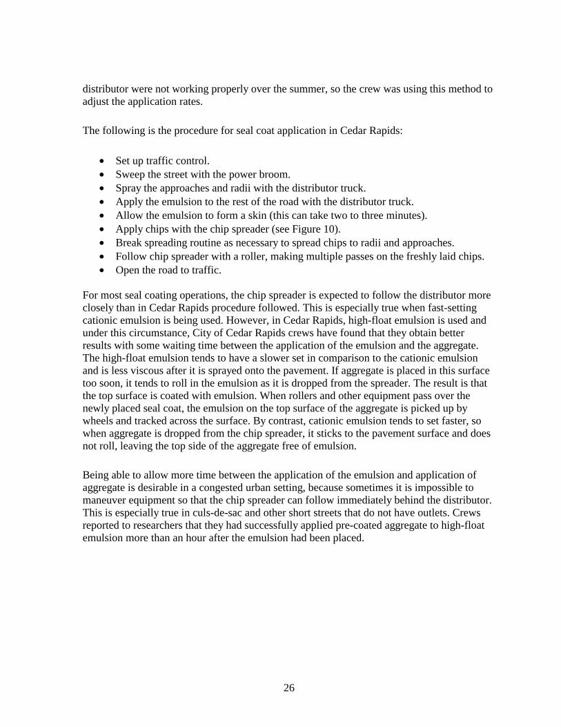
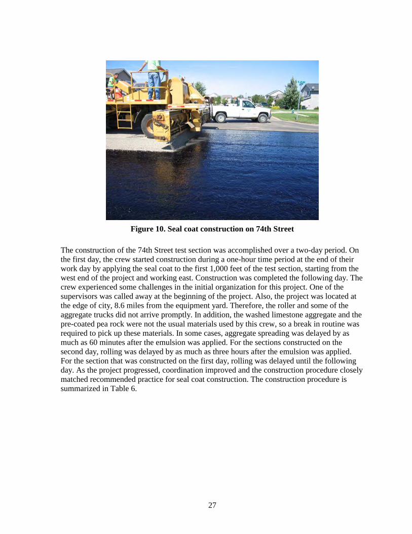
bull Set up traffic control bull Sweep the street with the power broom bull Spray the approaches and radii with the distributor truck bull Apply the emulsion to the rest of the road with the distributor truck bull Allow the emulsion to form a skin (this can take two to three minutes) bull Apply chips with the chip spreader (see Figure 10) bull Break spreading routine as necessary to spread chips to radii and approaches bull Follow chip spreader with a roller making multiple passes on the freshly laid chips bull Open the road to traffic
For most seal coating operations the chip spreader is expected to follow the distributor more closely than in Cedar Rapids procedure followed This is especially true when fast-setting cationic emulsion is being used However in Cedar Rapids high-float emulsion is used and under this circumstance City of Cedar Rapids crews have found that they obtain better results with some waiting time between the application of the emulsion and the aggregate The high-float emulsion tends to have a slower set in comparison to the cationic emulsion and is less viscous after it is sprayed onto the pavement If aggregate is placed in this surface too soon it tends to roll in the emulsion as it is dropped from the spreader The result is that the top surface is coated with emulsion When rollers and other equipment pass over the newly placed seal coat the emulsion on the top surface of the aggregate is picked up by wheels and tracked across the surface By contrast cationic emulsion tends to set faster so when aggregate is dropped from the chip spreader it sticks to the pavement surface and does not roll leaving the top side of the aggregate free of emulsion
Being able to allow more time between the application of the emulsion and application of aggregate is desirable in a congested urban setting because sometimes it is impossible to maneuver equipment so that the chip spreader can follow immediately behind the distributor This is especially true in culs-de-sac and other short streets that do not have outlets Crews reported to researchers that they had successfully applied pre-coated aggregate to high-float emulsion more than an hour after the emulsion had been placed
26
Figure 10 Seal coat construction on 74th Street
The construction of the 74th Street test section was accomplished over a two-day period On the first day the crew started construction during a one-hour time period at the end of their work day by applying the seal coat to the first 1000 feet of the test section starting from the west end of the project and working east Construction was completed the following day The crew experienced some challenges in the initial organization for this project One of the supervisors was called away at the beginning of the project Also the project was located at the edge of city 86 miles from the equipment yard Therefore the roller and some of the aggregate trucks did not arrive promptly In addition the washed limestone aggregate and the pre-coated pea rock were not the usual materials used by this crew so a break in routine was required to pick up these materials In some cases aggregate spreading was delayed by as much as 60 minutes after the emulsion was applied For the sections constructed on the second day rolling was delayed by as much as three hours after the emulsion was applied For the section that was constructed on the first day rolling was delayed until the following day As the project progressed coordination improved and the construction procedure closely matched recommended practice for seal coat construction The construction procedure is summarized in Table 6
27
Table 6 Construction summary for Cedar Rapids 74th Street test section
Section Aggregate Spreading Rolling Comment Pre-coated 38-inch 20 to 30 minutes after Following day Performed during late limestone chips on emulsion application afternoon of the first first 1000 feet extra aggregate day
dumped on road Pre-coated 38-inch 30 to 60 minutes after Two to three hours Performed at the limestone chips for emulsion application after emulsion beginning of the second balance of test section application day Washed 38-inch 30 to 60 minutes after One to two hours after The limestone chips limestone chips emulsion application emulsion application were dusty Pre-coated 38-inch Chip spreader followed Less than one hour The pre-coated pea rock pea rock distributor truck after emulsion was very dirty because
application it had been previously used
Double seal coat with Chip spreader followed Roller followed chip Procedure was followed 12-inch washed distributor truck spreader for both courses limestone first course construction followed 38-inch pre-coated closest to recommended limestone second best practices on this course section
Council Bluffs Test Section
College Road
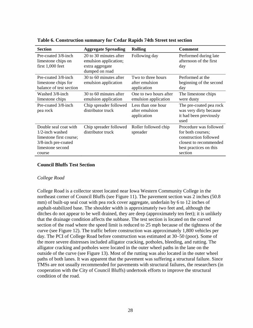
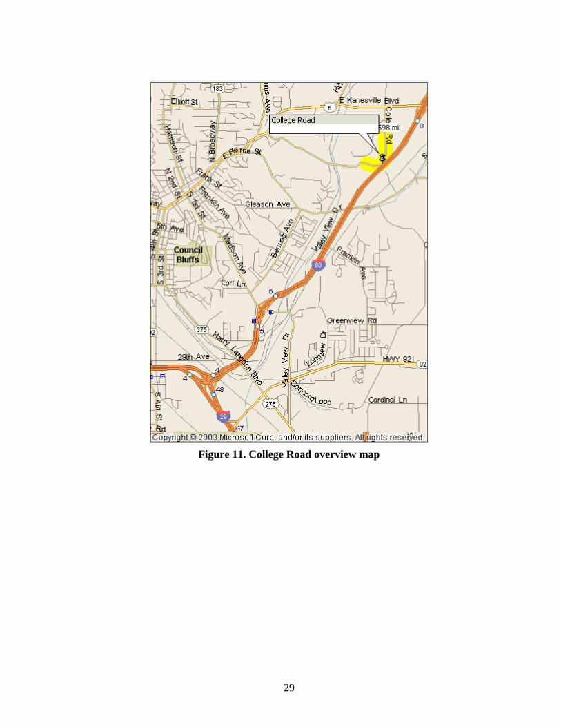
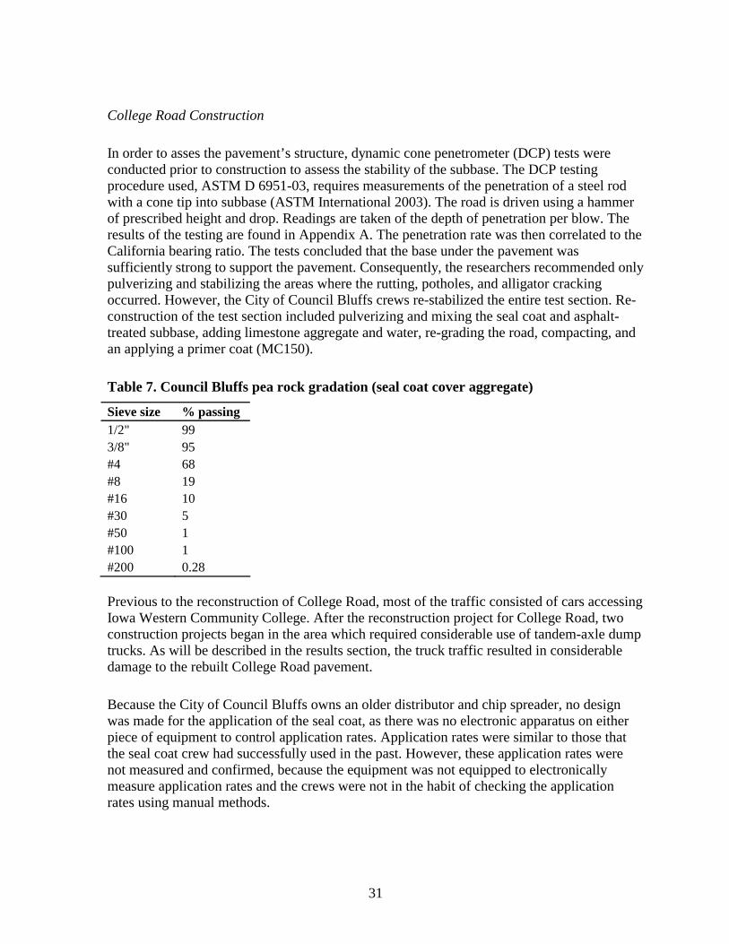
College Road is a collector street located near Iowa Western Community College in the northeast corner of Council Bluffs (see Figure 11) The pavement section was 2 inches (508 mm) of built-up seal coat with pea rock cover aggregate underlain by 6 to 12 inches of asphalt-stabilized base The shoulder width is approximately two feet and although the ditches do not appear to be well drained they are deep (approximately ten feet) it is unlikely that the drainage condition affects the subbase The test section is located on the curved section of the road where the speed limit is reduced to 25 mph because of the tightness of the curve (see Figure 12) The traffic before construction was approximately 1800 vehicles per day The PCI of College Road before construction was estimated at 30ndash50 (poor) Some of the more severe distresses included alligator cracking potholes bleeding and rutting The alligator cracking and potholes were located in the outer wheel paths in the lane on the outside of the curve (see Figure 13) Most of the rutting was also located in the outer wheel paths of both lanes It was apparent that the pavement was suffering a structural failure Since TMSs are not usually recommended for pavements with structural failures the researchers (in cooperation with the City of Council Bluffs) undertook efforts to improve the structural condition of the road
28
Figure 11 College Road overview map
29
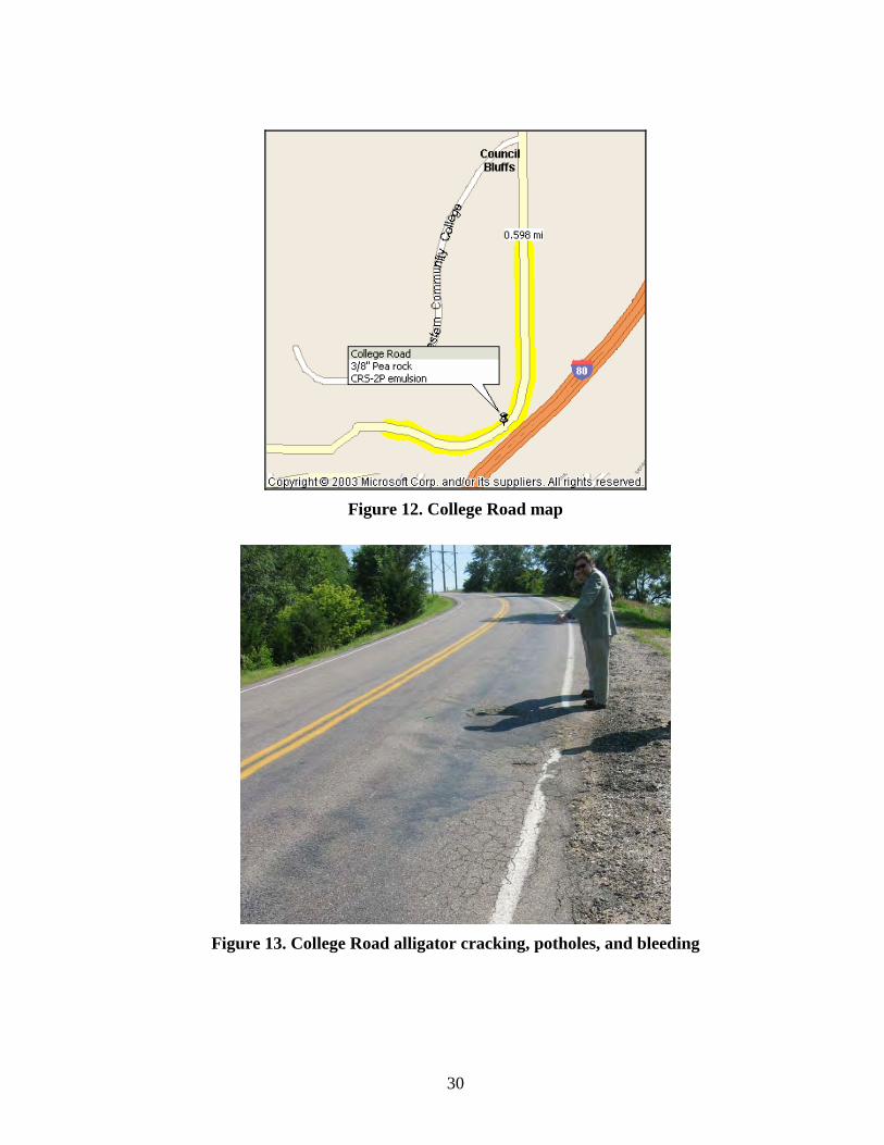
Figure 12 College Road map
Figure 13 College Road alligator cracking potholes and bleeding
30
College Road Construction
In order to asses the pavementrsquos structure dynamic cone penetrometer (DCP) tests were conducted prior to construction to assess the stability of the subbase The DCP testing procedure used ASTM D 6951-03 requires measurements of the penetration of a steel rod with a cone tip into subbase (ASTM International 2003) The road is driven using a hammer of prescribed height and drop Readings are taken of the depth of penetration per blow The results of the testing are found in Appendix A The penetration rate was then correlated to the California bearing ratio The tests concluded that the base under the pavement was sufficiently strong to support the pavement Consequently the researchers recommended only pulverizing and stabilizing the areas where the rutting potholes and alligator cracking occurred However the City of Council Bluffs crews re-stabilized the entire test section Reshyconstruction of the test section included pulverizing and mixing the seal coat and asphalt-treated subbase adding limestone aggregate and water re-grading the road compacting and an applying a primer coat (MC150)
Table 7 Council Bluffs pea rock gradation (seal coat cover aggregate)
Sieve size passing 12 99 38 95 4 68 8 19 16 10 30 5 50 1 100 1 200 028
Previous to the reconstruction of College Road most of the traffic consisted of cars accessing Iowa Western Community College After the reconstruction project for College Road two construction projects began in the area which required considerable use of tandem-axle dump trucks As will be described in the results section the truck traffic resulted in considerable damage to the rebuilt College Road pavement
Because the City of Council Bluffs owns an older distributor and chip spreader no designwas made for the application of the seal coat as there was no electronic apparatus on either piece of equipment to control application rates Application rates were similar to those that the seal coat crew had successfully used in the past However these application rates werenot measured and confirmed because the equipment was not equipped to electronicallymeasure application rates and the crews were not in the habit of checking the application rates using manual methods
31
Usually for roads that exhibit distress similar to that which was found on College Road the City of Council Bluffs pulverizes reshapes and re-compacts the built-up seal coat and asphalt-treated base Virgin aggregate may be added to increase stability and water may be added to improve compaction After compaction the surface is sprayed with an asphalt cutshyback primer (usually MC 70 at 03 galyd2 and covered with blotting sand The primer is intended to penetrate into the re-compacted base and provide a measure of water resistance After the primer has had a week to penetrate a seal coat is usually placed Council Bluffs typically uses high-float emulsion and pea rock for its seal coats Council Bluffs finds that in comparison to cationic emulsions the high-float emulsion allows more time to elapse between the spraying of emulsion and the placing of aggregate This allows greater flexibility in coordinating equipment operations Also the high-float emulsion is more likely to properly bind dusty aggregate Pea rock is used because it is an economical locally sourced cover aggregate (see Table 8) Council Bluffs has experimented with locally sourced limestone chips but these have not been sufficiently durable under traffic Aggregates that are not locally sourced are considered too expensive
Table 8 Pea rock gradation for Council Bluffs seal coat cover aggregate (mineral aggregate for armor coat)
Sieve size retained 34 0 38 0ndash6 10 65ndash100 50 90ndash100 200 96ndash100
Council Bluffs public officials have found these roads to be satisfactory for rural areas within the city limits However it is typical that such roads develop areas of instability alligator cracks and then potholes similar to those which College Road experienced Researchers were asked to recommend a seal coating system that might improve that performance
Researchers theorized that small cracks may be developing in the seal coat and allowing water to penetrate the base where it initiates instability problems They recommended the use of a polymer-modified seal coat binder that could resist cracking to a greater degree even if the base was yielding slightly under traffic Originally a high-float polymer-modified emulsion was recommended However that emulsion could not be locally manufactured A cationic polymer-modified emulsion (CRS 2P) was available so that emulsion was selected for use with this project
32
Figure 14 Stabilization of College Road
The following construction procedure was used to pulverize and re-compact the road
bull Scarify the seal coat using ripper teeth on the front of a motor grader bull Scarify the asphalt-treated base using ripper teeth on the front of a motor grader bull Work the material into windrows using the motor grader bull Pulverize and mix the windrowed material with three to four passes of a soil mixer
(see Figure 14) bull Add virgin aggregate to strengthen the mix and to raise the grade (Between 80 and
100 tons were used for this test section) Add soil from ditches to provide fines to fill the void spaces between the pieces of virgin aggregate
bull Set the crown or super elevation using the motor grader bull Compact the material using a pneumatic tire roller bull Apply the primer using a distributor truck (Before primer was applied the surface
was scarified and re-compacted because the crew thought that the surface was too tightly bound to allow the primer to penetrate)
bull Apply blotting sand using a winter maintenance sand spreader
Although the City of Council Bluffs preferred to allow the primer to penetrate for a week before placing the seal coat this test section was constructed at the end of the construction season it was necessary to seal coat three days after the primer was placed in order to finish before the close of the construction season
33
The crew was instructed to use its usual application rate for binder and cover aggregate while seal coating The chip spreader and distributor were not equipped to measure adjust and modify the application rates during the application process Therefore the application rates cited herein are estimated
At the beginning of the seal coat application operation the crew struggled to coordinate equipment in order to cover the binder and roll the cover aggregate within two minutes as is recommended for CRS 2P binder However after a rhythm was established the crew accomplished the work in accordance with the expected practice for these materials
West Des Moines Test Sections
Aspen Drive
Aspen Drive is a residential street located in north-central West Des Moines (see Figure 15 and Figure 16) Before construction Aspen Drive was a Portland concrete cement (PCC) pavement with an asphalt concrete cement (ACC) overlay of unknown thickness The street has concrete curbs gutters and storm sewers which provide excellent drainage The major distresses previous to construction were low- to medium-severity reflective cracking and LampT cracking (see Figure 17) Many of the reflective cracks had been sealed in 1991 The test section is located in a subdivision and based on previous experience city officials estimated an ADT of approximately 500 The PCI of the test section was 49 Citizen complaints about aesthetics were the main reason that a new surface was desired
Figure 15 West Des Moines overview map
34
Figure 16 Aspen Drive map
Figure 17 Aspen Drive before construction
Micro-surfacing was selected for Aspen Drive despite the fact that slurry seal is usually considered to be satisfactory for such a low-volume application This is because the City of West Des Moines wanted to have micro-surfacing test sections on the higher volume roads elsewhere in the city such as the Fourth Street and Vine Street location described later A construction contract that included only Fourth Street and Vine Street would not have been sufficiently large to attract contractors Aspen Drive was added to the contract because the city desired to maintain this street in the near future A limestone aggregate with a modified Type III gradation was used for the micro-surfacing mix for Aspen Drive (see Table 9) Further information on the micro-surfacing can be found in ldquoISSA Recommended Performance Guidelines for Micro-Surfacingrdquo (International Slurry Seal Association 2003)
35
Table 9 Type III micro-surfacing gradations (ISSA method A143)
Sieve Size Passing 38 100 4 70ndash90 8 45ndash70 16 28ndash50 30 19ndash34 50 12ndash25 100 7ndash18 200 5ndash15
Researchers had experience in previous phases of this project which indicated that the Type III gradation band could produce an aggregate that is too coarse for good performance therefore they specified a modified gradation with more fines (see Table 10) The added fines help the spreader apply a tighter surface with fewer drag marks as they prevent the larger aggregate from getting stuck underneath the screed by creating more friction between the pavement the fine material and coarse material
Table 10 Type III micro-surfacing gradations (West Des Moines specifications)
Sieve Size Passing 38 100 4 70ndash100 8 45ndash70 16 28ndash50 30 19ndash34 50 13ndash25 100 10ndash18 200 8ndash15
In the past contractors have developed slurry seals that cure very quickly like micro-surfacing These slurry seals set within 15 hours which makes them difficult to distinguish between actual micro-surfacing Reportedly a rapidly setting slurry seal is not able to cure within the specified 15 hours at night because it needs heat from the sunlight to cure quickly To ensure that a contractor is providing micro-surfacing and not a quick-setting slurry seal some jurisdictions (MnDOT in particular) specify placing test sections at night The contractor is required to lay a short strip of micro-surfacing after sunset If the surface does not cure within the specified time the agency has an indication that they may not be getting a proper micro-surfacing mix and can require the contractor to try other test sections until the mix passes
When micro-surfacing is laid some pieces of aggregate stand on edge this increases tire noise (see Figure 18) After the aggregate has been worked down to its side by traffic the added tire noise diminishes In order to force the aggregate pieces to lay down more quickly
36
a requirement of making five passes with a pneumatic tire roller was specified in the contract documents for the construction project However during construction researchers and city engineers concluded that there was no noticeable improvement in aggregate orientation so the use of the roller was ceased
Figure 18 Micro-surfacing aggregate before and after traffic
Fourth Street and Vine Street
Fourth Street is a collector street located on the east side of West Des Moines (see Figure 15 and Figure 19) Before construction Fourth Street was a PCC pavement with an ACC overlay of unknown thickness Fourth Street and Vine Street both have concrete curbs gutters and storm sewers which provide excellent drainage The major distresses previous to construction were low-severity reflective cracking and LampT cracking (see Figure 20) Many of the cracks had been sealed in 1993 The test section is located in a residentialcommercial area There is an industrial company on the north end of the test section so there is a small amount of truck traffic delivering to that business The estimated ADT is approximately 2000 for Fourth Street
Vine Street is a collector street located on the east side of West Des Moines Before construction Vine Street was a PCC pavement with an ACC overlay of unknown thickness The major distresses previous to construction were low-severity reflective cracking and LampT cracking (see Figure 21) There was also a moderate amount of low-severity (14 inndash12 in) to medium-severity (12 inndash1 in) rutting Many of the cracks had been sealed and the seals were in good condition The test section is located in a residentialcommercial area and has a low amount of truck traffic which services surrounding retail stores The estimated ADT is approximately 5000ndash6000
Both limestone and quartzite aggregate were used for the Type III micro-surfacing mix used on Fourth Street and Vine Street Researchers and the City of West Des Moines desired to have a direct comparison between quartzite and limestone micro-surfacing aggregate Typically quartzite micro-surfacing aggregate is specified because it is thought to have more consistent chemical properties that provide a more predictable reaction with the micro-surfacing emulsion Although micro-surfacing has the advantage of curing quickly it also has the disadvantage of reacting and coagulating quickly in the presence of clay minerals The use of quartzite was thought to eliminate this disadvantage However the nearest source of quartzite was in south-eastern South Dakota and transportation costs added considerably to
37
the total cost of the aggregate Therefore it was considered desirable to identify a micro-surfacing aggregate that was sourced within Iowa Iowa limestone had been used as micro-surfacing aggregate on County Highway N28 in Pocahontas County Against this background the City of West Des Moines specified limestone micro-surfacing aggregate
Figure 19 Street map of Vine and Fourth
Figure 20 Fourth Street before construction
38
Figure 21 Vine Street before construction
Aspen Drive Fourth Street and Vine Street Construction
After the specifications were written and finalized and the plans had been developed the job was put out to bid Two contractors responded and the contract was awarded to Sta-Bilt Construction based out of Harlan Iowa Sta-Bilt had been applying micro-surfacing for at least eight years and had been applying the surface to highways in Nebraska throughout the summer that this project took place Because the contract was relatively small compared to other projects the West Des Moines project was not scheduled until the end of the summer Due to equipment breakdowns the project was further delayed until October
The first part of the construction was the application of the night test section (see Figure 22) Even though the air temperature dropped to 50degF during application the micro-surfacing still cured in less than 45 minutes this indicated that the mix was acceptable Construction commenced the next day (see Figure 23) The micro-surfacing crew appeared to the researchers to be very experienced There was concern that the temperatures were lower than desirable however they were above the range specified for construction (ie the surface should be no less than 50degF and rising)
39
Figure 22 Night test section construction
Figure 23 Micro-surfacing construction
40
RESULTS AND DISCUSSION
Cedar Rapids Results
The survey results for Cedar Rapids test sections are summarized and analyzed herein For detailed results see Appendix B
Vermont Avenue
The post-construction survey revealed that the pavement condition index (PCI) for Vermont Avenue was 72 which places it in the rating category of ldquovery goodrdquo A conservative estimate of the original PCI is 56 which falls in the rating category of ldquogoodrdquo (The estimate was based on a photo log and on estimated percentages of LampT cracking and alligator cracking) This means that there was an estimated increase of 16 points for the PCI At the time of the post-construction survey the seal coat was in very good condition with no raveling or bleeding The main distress was light-severity reflective cracking from the previous seal coat The chipmat also performed very well There was no reflective cracking in the areas where the chipmat was placed (see Figure 24) Researchers chose not to place fabric over some areas of alligator cracking in order to provide a comparison In those places the alligator cracking quickly reflected through to the new seal coat even before the start of the subsequent winter (see Figure 25) The average deduct values for the test section are displayed in Figure 26
There were a few concerns with the chipmat (1) it would not prevent reflective cracking (2) it would not bond well to the existing seal coat and (3) there would be noticeable bleeding over the chipmat Inspection after the first winter indicated no such distresses had developed The city engineer very pleased with the chipmat is considering the possibility of using it again in the future
Figure 24 No reflected alligator cracking (chipmat)
41
Figure 25 Reflected alligator cracking (no chipmat)
Vermont Avenue Distresses
0
2
4
6
8
10
12
Alligator cr Reflective cr Rutting Raveling
Ave
rag
e D
edu
ct V
alu
es
1122004
5202005
Figure 26 Vermont Avenue deduct values
74th Street in Cedar Rapids
The post-construction survey revealed that the overall PCI for 74th Street was 72 (very good) A conservative estimate of the original PCI is 62 (good) This estimate was based on a photo log of the test section The estimated increase in the PCI value is 10 As was expected results
42
varied with each of the various types of aggregates This ldquovery goodrdquo rating is a strong indicator of a pavement with good structural stability Examination of the actual distress deduct scores indicate very low amounts of cracking rutting and alligator cracking which are all structural-related distresses However the test section appears to be in very poor condition because of surface distresses such as raveling and bleeding These distresses are not weighted as heavily in the calculation of the PCI because they are only surface distresses and are not indicative of a pavement with poor structural stability The average deduct values for the test section are shown in Figure 27
74th Street Distresses
0
2
4
6
8
10
12
14
16
18
Alligator cr Drop off LampT cr Rutting Raveling
Ave
rag
e D
edu
ct V
alu
es
1122004
5202005
Figure 27 74th Street deduct values
The section of seal coat that performed the best was the Section I (see Figure 28) with the 38-inch pre-coated aggregate This section yielded a PCI of 81 (very good) Other than slight raveling the seal coat was performing with no visible distress The seal coat lost many PCI points because of rutting and other distresses that existed before construction of the new seal coat Because a seal coat does not add any structure to a pavement a seal coat does not address structural distresses It is interesting to note that Section I included the 1000-foot section of the pre-coated aggregate that was not rolled until the day after the aggregate was applied This is an indication that the emulsion and the pre-coated chips bonded to one another and is evidence of the robustness of the pre-coated chip and high-float emulsion combination
43
Figure 28 74th Street pre-coated chips
The 38-inch washed limestone chip section (see Figure 29) did not perform particularly well its PCI rating was 63 (good) The relatively low PCI was caused by the large amounts of high-severity raveling Other minor distresses included dips and low-severity rutting which were pre-existing A large area of the seal coat was heavily raveled due to snowplow damage The raveling problem might be attributed to poor bonding caused by the dustiness of the aggregate that was used and the lack of the compaction by the pneumatic tire roller The aggregate had been placed for three to four hours before the roller seated it It is possible that the raveling may have been less severe had a roller been used immediately after placement because much of the raveling was outside the wheel paths (This is because the chips in the wheel path were seated in the emulsion by the passing traffic) The city engineer also mentioned that this portion of the test section created large amounts of dust for several days after construction which caused numerous citizen complaints The city attempted to reduce the dust by washing the section with a water truck but this effort resulted in limited success
Figure 29 74th Street washed limestone chip
44
The 38-inch pea rock test section (see Figure 30) had more raveling problems in comparison to the test sections that used pre-coated limestone aggregate for the top course The PCI rating for the 38-inch pea rock test section was 66 which is in the performance category of ldquogoodrdquo Most of the distress deducts resulted from large amounts of high-severity raveling Other minor distresses included dips and low-severity rutting which pre-existed construction This section was similar to the washed limestone chip section in that there was considerable medium- to high-severity raveling Again the raveling in this section may have been caused by dirty aggregate and a lack of rolling by the pneumatic tire roller Figure 31 shows how much fine material was on the chips evidenced by the dusty residue left on a hand after handling the aggregate This section was also the target of complaints by neighboring property owners regarding excessive dust generation
Figure 30 74th Street pea rock
Figure 31 Dusty washed limestone and dirty pea rock chips
45
The double seal coat sectionmdash12-inch washed limestone chip base with a 38-inch pre-coated limestone chipmdashperformed quite well with an ldquoexcellentrdquo PCI rating of 95 (see Figure 32) This section experienced only slight bleeding and other distresses that were present before construction which cannot be addressed by seal coating There was one area with medium-severity alligator cracking and rutting however these distresses were not included in the survey because they were outside the sample boundaries The lack of raveling can be attributed to the fact that this test section was rolled by the pneumatic tire roller immediately after the application of both layers of chips There were concerns that this section would have issues with bleeding however as of May 16 2005 there was no bleeding on this section
Figure 32 74th Street double seal coat
Council Bluffs Results
The survey results for Council Bluffs test sections are summarized and analyzed herein For detailed results see Appendix C
College Road in Council Bluffs
The fall 2004 post-construction survey indicated that the road was in ldquoexcellentrdquo condition with a PCI near 100 However by the time the spring 2005 survey was conducted the road had deteriorated so that that there was little to no improvement in comparison to the pre-construction condition of College Road The new PCI of the road was 48 which is a ldquofairrdquo condition rating and the estimated previous PCI was approximately 30ndash50 The new PCI value does not include the portion of the test section adjacent to the north construction site (mentioned later) where earthwork was occurring and the resulting truck traffic caused a total failure of the pavement This portion was left out because it did not represent the condition of the rest of the pavement (The PCI values for these two sections were 29 which is
46
categorized as poor and 11 which is categorized as very poor) The average deduct values for College Road not including the failed sections are found in Figure 33 It should be noted that when performing PCI surveys on seal coat roads the surveyor did not consider construction defects as distresses because the investigation was attempting to focus on how structure and surface of a well-constructed road would perform An example of a construction defect is a series of grooves left from a motor graderrsquos ripper teeth before the application of the first seal coat although the grooves could be considered rutting they are not a sign of structural distress or of a surface distress and they were thus not included in the survey
College Road Distresses
0
2
4
6
8
10
12
14
16
Alligator cr Bleeding Potholes Rutting Raveling
Ave
rag
e D
edu
ct V
alu
es
10292004
5172005
Figure 33 College Road deduct values (The 10292004 survey had zero deduct values)
The distresses in the new seal coat were similar to that of the pre-construction condition (see Figure 34) Low- to high-severity rutting alligator cracking bleeding and potholes had developed When researchers compared a photo log of the test section before construction to the condition of the test section after construction it was determined that the distresses in the new seal coat were located in the same regions as those of the original seal coat even though the entire road was re-stabilized As with the original seal coat the majority of the distresses were located in the outer lane especially in the outer wheel path The area adjacent to the entrance of the construction site had failed due to the heavy truck traffic High-severity rutting alligator cracking bleeding and raveling were the most prominent distresses near the entrance Interestingly the areas that were in excellent condition before construction were the same areas that were in good condition for the post-construction survey
47
Figure 34 College Road alligator cracking
The intended goal of using the polymer-modified emulsion was to prevent the development of bleeding and to reduce the amount of structural distressmdashmainly alligator cracking and potholesmdashcaused by small cracks forming in the surface that allow water to reach the subbase and cause the base to become weak However the use of the polymer-modified emulsion did not prevent the redevelopment of bleeding and cracking distresses The recurrence of distress is not necessarily a failure of the polymer-modified emulsion Challenges during the construction of the test section the lack of stability of the subbase and the excessive truck traffic are also likely causes of the failure
The most probable cause for the various structural failures located throughout the test section was overloading of the pavement caused by the extra truck traffic After discussions with the city engineer the college adjacent to the test section removed approximately 350000 cubic yards of earth all of which was hauled by tandem-axle dump trucks that used the test section as a part of their haul route Figure 35 shows the truck route (dashed line) that was used to access Interstate 35 The trucks entered the test section at its south end and drove north to the on-ramp for Interstate 35 The trucks used the test section as a return road as well It can be reasonably assumed that each truck carried approximately 10ndash12 cubic yards of earth which means that in the months after construction the test section was traversed by approximately
48
35000 fully loaded dump trucks This number does not include traffic to and from the north construction site which also included dump trucks removing an unknown amount of earth and using College Road to access Interstate 35 According to the city engineer Iowa Western Community College plans to remove another one million cubic yards and the test section will be traversed by all of this truck traffic as well
Figure 35 College Road construction map
An analysis was conducted to assess the ability of the College Road pavement to withstand the truck traffic that was imposed on it (see Appendix D) The analysis indicated that an emulsion-mixed base with coarse aggregate six inches deep would be required for the truck traffic This base requires a structural number of 18 (The structural number is an index of the strength of base required to carry a defined load of traffic) It seems likely that the design and quality control requirements contemplated in the analysis exceed those that were applied to the base for College Road The existing base was approximately six inches of pulverized seal coat and base material that was wet compacted in lifts with no additive emulsion The mix did contain some binder from previous seal coats and the emulsion binder from previous stabilization projects This base likely had a structural number ranging from 042 to 066 This range is much lower than the required number of 18 and is insufficient for the truck traffic This shows that the existing pavementrsquos structure should not have been expected to support the truck traffic that the pavement experienced
West Des Moines Results
The survey results for West Des Moines test sections are summarized and analyzed herein For detailed results see Appendix E
49
Aspen Drive
The post-construction survey revealed that there was considerable improvement in the condition of the road The original PCI of the Aspen Drive was 49 and the new PCI was 82 an increase of 33 points to a ldquovery goodrdquo rating Figure 36 shows the average deduct values for the various surveys performed on Aspen Drive Various reflected cracks were the only distresses present in the new micro-surfacing Many of the original reflected cracks in the overlay also reflected through the new micro-surfacing treatment This section was the only section for which researchers had the original surveys (Recall that the others were lost in an auto theft) The original total for all of the cracks on six sample survey sections was 2802 feet which includes low- medium- and high-severity reflective and LampT cracking (see Figure 37) As of May 16 2005 the total amount of cracking is 1605 feetmdasha 43 decrease in cracking This number only includes reflective cracking because the PCC joint cracks as well as the LampT cracks in the overlay reflected through the micro-surfacing but no new LampT cracks will form in the micro-surfacing This crack reflection is typical of micro-surfacing treatments The only other distress in the original overlay was light-severity alligator cracking As of May 16 2005 none of the alligator cracking had reflected through the micro-surfacing The micro-surfacing appears to be performing well (see Figure 38) In a few high spots a snowplow sheared off the high parts of the limestone aggregate but enough aggregate still remains to cover the original pavement
Aspen Drive Distresses
-
5
10
15
20
25
30
35
Alligator cr Reflective cr LampT cr Patching
Ave
rag
e D
edu
ct P
oin
ts
7302004
1122004
5162005
Figure 36 Aspen Drive deduct values
50
8 L 8 M
8 H
-
1542
1354
63
5 -
-
200
400
600
800
1000
1200
1400
1600
Lin
eal
Fee
t (L
F)
ORIGINAL
MICRO-SURFACING
Figure 37 Reflective cracking on Aspen Drive by severity level
Figure 38 Reflective cracking on Aspen Drive
51
Fourth Street and Vine Street
The post-construction survey revealed that the PCI for Fourth Street increased from an estimated pre-construction PCI of 81 (very good) to 86 (excellent) Because preconstruction
Ave
rag
e D
edu
ct V
alu
esurvey data was lost in the previously mentioned auto theft the pre-construction PCI was estimated by surveying Maple Street a pavement with a condition similar to that of Fourth Street and Vine Street before the application of the micro-surfacing However unlike Fourth and Vine Streets Maple Street not have any rutting which makes comparison challenging In order to adjust for rutting the rutting deduct values from the Vine Street survey (see Figure 39) were included in the Maple Street survey (see Figure 40) to draw a more accurate estimate of the pre-construction condition of Vine Street The PCI value for Maple Street with the Vine Street rutting adjustment was 70 (good) The final PCI for Vine Street was 80 with a rating of ldquovery goodrdquo and a PCI increase of 10
Similar to Aspen Drive the primary distress for both Fourth Street and Vine Street was reflected cracking Vine Street had experienced some light-severity rutting before construction and the micro-surfacing did not fill in the ruts (Rut filling was not specified in the contract) The graphs do not include pre-construction data
Vine Street Distresses
18
16
14
12
101122005
51620058
6
4
2
0
Reflective cr Rutting
Figure 39 Vine Street deduct values
52
M aple Stree t Distresses (with rutting)
0
2
4
6
8
10
12
14
Ref lective cr LampT cr Raveling Rutting
Ave
rag
e D
edu
ct V
alu
es
5162005
Figure 40 Maple Street deduct values (no TMS) with rutting
Both types of aggregatemdashquartzite and limestonemdashwere used for both streets and there was no noticeable difference in performance The two mixes of micro-surfacing using different aggregates are experiencing the same types and amounts of distresses The sections of micro-surfacing with limestone aggregate seemed to have a tighter surface texture because there were a higher proportion of fines in the limestone gradation Figure 41 shows the color of the limestone aggregate in comparison to the quartzite aggregate which has a pink color
Quartzite
Limestone
Figure 41 Micro-surfacing on Fourth Street
53
A common problem with micro-surfacing and slurry seals is delaminating caused by snow plows However there was only one spot approximately five square feet where a snow plow had completely removed the micro-surfacing mix
Noise Testing on Fourth Street in West Des Moines
After micro-surfacing has been laid it is often noisier in comparison to the previous surface and the type of tire noise produced commonly gives people the perception that the surface is rough in comparison to other surfaces especially hot mix asphalt This extra noise is emitted from the tires and is caused by added air space between the tire and the aggregate that is standing on its edge after the micro-surfacing has been laid (see Figure 18) However after a few months under traffic the aggregate becomes reoriented by tire contact producing a smoother surface and a less noisy road The city engineer in West Des Moines was concerned with the added noise and asked for sound testing to be performed
Researchers conducted noise level tests to compare tire noise on a control section of a new asphalt overlay with the noise level on the micro-surfacing A decibel meter a device that measures the decibel level was purchased to conduct the tests The operator of the decibel meter stood on the sidewalk 15 feet away from the traffic and the test vehicle traveled in the closest lane (see Figure 42) To isolate the tire noise from the test vehicle the test vehicle coasted by the decibel meter at 25 mph in order to reduce the amount of engine or brake noise that might mask the tire noise Masking is ldquoa situation where a dominant or nearly dominant sound or noise component of a noise source reduces or eliminates the audibility of other sound (or noise) components of a noise sourcerdquo (Geib and Wood 2001)
Figure 42 Sound testing layout
54
Researchers used two different test vehicles a 2002 Ford Taurus and a 2000 Chevrolet 3500 work truck with dual rear tires The truck was supplied by the West Des Moines Public Works Department A sampling of vehicles passing by was also taken to see if there was a difference in ambient noise In the parlance of statistical experiment design this constituted a ldquochunkrdquo sample including any cars heavy trucks and city buses that passed the site at the time the test was being conducted A test was also taken to compare the interior noise in the Ford Taurus when riding on the micro-surfacing to the noise when riding on an unsurfaced asphalt overlay (see Appendix G)
As was expected there was a difference in sound intensity between the micro-surfacing and the asphalt overlay The difference was equal to 39 dB for the truck 42 dB for the car 48 dB for the inside of the car However MnDOT defines a difference of 3 dB as barely perceptible a difference of 5 dB is generally considered to be a substantial change in noise and a 10 dB change is doubling or halving the perceived loudness (Geib and Wood 2001) After three months of traffic the differences in average loudness between the micro-surfacing and the asphalt overlay had diminished The differences in average sound intensity between the two surfaces were 04 dB for the truck 13 dB for the car and 72 dB for inside the car (see Table 11) The difference in tire noise from outside the car and truck was no longer perceptible However test results indicate that there was a larger difference in interior sound levels during the second test This larger difference was unexpected because the exterior noise levels dropped the added sound is caused by the tires
Table 11 Differences in average loudness (in decibels)
January 19 2005 June 10 2005 Car Truck Inside car Car Truck Inside car
Asphalt 675 673 612 728 648 549 Micro-surfacing 714 715 660 732 660 621 Difference 39 42 48 04 13 72
The average sound intensity for the test vehicles during the test in March cannot be compared to the sound intensity during the test in June because the temperature was notably differentmdash 36degF for the January 19 2005 test and 80degF for the June 10 2005 testmdashand different vehicles were used for the testing The reason that different test vehicles were used was that it was not possible to get the same exact vehicles from the Iowa State University Motor Pool The difference in loudness for each of the test vehicles on each of the surfaces on one test day shows the difference in loudness (see Figure 43 and Figure 44) The chunk sampling of cars trucks and buses passing by also showed no difference in the decibel level with the average decibel level of the micro-surfacing being 15 dB higher than that of the asphalt (see Figure 45)
55
Sound readings from 1192005
Dec
ibel
s 760
740
720
700
680
660
640
Car (MS)
Car (Asphalt)
Truck MS
Truck Asphalt
Figure 43 First sound readings (in order of intensity)
Sound readings from 6102005
580
600
620
640
660
680
700
720
740
760
Dec
ibel
s Car (MS)
Car (Ashpalt)
Truck (MS)
Truck (Asphalt)
Figure 44 Second sound readings (in order of intensity)
56
Chunk Sampling 6102005
00
100
200
300
400
500
600
700
800
900 D
ecib
els
Micro-s urfacing
As phalt
Note that micro-surfacing and asphalt measurements are not paired
Figure 45 Chunk sampling of cars buses and trucks (in order of intensity)
Additional Testing
In addition to the performance surveys described in this section a survey of each of the demonstration sections was undertaken in November of 2005 The results of these surveys are described in Appendix F
57
CONCLUSIONS AND RECOMMENDATIONS
The conclusions from this project were developed after reviewing observations from the various test sections constructed Statistical analyses were not performed on the test section data to interpret the results Each test section stands as its own case study and should not be compared to others for the purpose of determining which surface was the most successful The test sections stand as examples of the various preventive maintenance techniques and materials that can be used to preserve pavements The various test sections were designed with techniques and materials that are common or available in Iowa so that cities and counties are able to reproduce the test sections To some extent the following conclusions are generalized for similar materials in geographic areas beyond Iowa Readers should not make such generalizations unless they are certain that the materials and conditions are similar to those of the test sections
Cedar Rapids Conclusions
bull The seal coats in Cedar Rapids that use a pre-coated limestone chips are performing better than the other types of aggregates including pea rock and washed (un-coated) limestone chips
bull The current program of using high-float emulsion HFE-90 and a pre-coated limestone chip for a seal coat appears to be successful because this is a very robust combination This combination has outperformed the other aggregates even though quality control was not rigorous the chips were not spread promptly after the emulsion was applied or rolled promptly after the chips were spread
bull The washed limestone chip and pea rock aggregate received numerous public complaints due to fugitive dust These combinations are recommended for areas where dust can be tolerated The dust on both the washed limestone chip and pea rock aggregate also may have caused a poor bond between the chips and the emulsion This poor bond may have resulted in the severe raveling that was observed by researchers
bull Emulsion can be used as a tack coat for a geotechnical fabricndashreinforced seal coat if the tack coat and fabric are given ample time to cure before the first seal coat is applied Sand can be used to blot the surface of the geotechnical fabric while the emulsion is curing Using chipmat with an emulsion as a tack coat appears to be a feasible and cost-effective solution for alligator cracking that does not deflect under load This conclusion is based on the construction of one demonstration section
Council Bluffs Conclusions
bull The College Road test section has not yielded the desired result with regard to pavement performance as measured by PCI The College Road test sectionrsquos poor performance can likely be attributed to the increase of heavy truck traffic Approximately 30000ndash35000 loaded tandem-axle dump trucks used College Road as
58
an entrance for a construction site within 6 months this is not typical daily traffic or typical loads for this road Had the test section received the same traffic load that was present before the construction took place it is the researchersrsquo opinion that the test section would not have had the same degree of structural failure
bull A conclusion could not be made from this research project regarding the effectiveness of polymer-modified emulsion The test section that was used to investigate this topic had a number of construction and traffic issues that muddled the results Although the benefits of polymers were not demonstrated in this research literature has shown that the use of polymers aids in chip retention helps prevent bleeding reduces temperature susceptibility and enhances the robustness of the seal coat
West Des Moines Conclusions
bull The use of micro-surfacing was successful as all three test sections are performing well There were no apparent differences in the performance of quartzite or limestone aggregate Since limestone is locally available and less costly its use should be strongly considered in the future
bull The higher proportion of fines in the limestone aggregate gradation for the micro-surfacing helped create a smoother and tighter surface in comparison to previous micro-surfacing projects on Iowarsquos system of primary roads (Jahren et al 1999) The modification of the recommended aggregate gradation should be further tested to verify this finding
bull The use of the pneumatic tire roller to smooth micro-surfacing and reduce noise was not found to result in noticeable improvement (based on one trial)
bull The sound testing conducted as part of this project showed that the exterior sound intensity of the micro-surfacing decreases as it is trafficked After several months of traffic the exterior loudness of micro-surfacing is similar to that of an HMA surface The difference in interior noise between hot mix asphalt and micro-surfacing increased from the first measurement (shortly after placement) to the second measurement (three months later)
General Conclusions
bull Thin maintenance surfaces are suitable preventive maintenance techniques for a municipal street departmentrsquos program to use for preserving existing pavements However careful attention should be paid to the proper timing of the application and to quality control during construction of the surface Aggregate and binder selection for seal coats should be taken very seriously and all options should be considered to determine the best combination that suits the needs of the city
bull Proper construction technique is one of the primary influences on the success of a TMS Failures of a TMS that occur early in its life can often be traced back to poor construction or quality control
bull Thorough planning is necessary for a successful TMS If proper planning is not performed the construction of the surface can be delayed or constructed with poor
59
quality control Construction late in the season can be rushed and the TMS performance can be compromised because the binder in the surface is not given necessary time to cure before the temperature drops
bull Construction of a TMS should not begin until all necessary equipment and materials are onsite Also construction should not begin until all necessary traffic control equipment is in place
bull The use of a pneumatic tire roller is important for embedding aggregate into the emulsion for successful seal coat construction The roller should be used immediately after application of the aggregate to ensure the best embedment (Apparently some delay is permissible if high-float emulsion is used) Although the pre-coated limestone chip seal coat in Cedar Rapids performed well without immediate roller embedment this is likely an exception due to the unusually robust combination of aggregate and binder that is afforded by the pre-coated limestone chips and high-float emulsion The other test sections and literature show that the use of a pneumatic tire roller is necessary
Recommendations
bull The use of polymer-modified emulsions should be tested again to determine the value added to a seal coat
bull The recommended aggregate gradation for the Type III micro-surfacing should be further tested to verify the findings from this research
bull Further investigation should be conducted regarding the use of a night test section as a preliminary indication of whether or not the micro-surfacing mixtures will perform properly
bull Further research and testing on the chipmat should be performed to verify the findings from this research
bull Additional noise testing should be performed on other micro-surfacing sections to verify the findings from this research
60
REFERENCES
AASHTO 1986 AASHTO Guide for Design of Pavement Structures vol 2 Washington DC American Association of State Highway and Transportation Officials
ASTM International 2003 Standard Test Method for Use of the Dynamic Cone Penetrometer in Shallow Pavement Applications ASTM D 6951-03 West Conshohocken PA ASTM International
Beatty TL et al 2002 Pavement Preservation Technology in France South Africa and Australia Report FHWA-PL-03-001 Washington DC Office of International Programs Federal Highway Administration
Brown NR 2003 Solution for distressed pavements and crack reflection Transportation Research Record 1819 313ndash317
Chen D-H D-F Lin and H-L Luo 2003 Effectiveness of preventative maintenance treatments using fourteen SPS-3 sites in Texas Journal of Performance of Constructed Facilities August 2003136ndash143
Davis L 2003 Chip sealing over fabric GFR Magazine JuneJuly 2003 Galehouse L et al 2005 Preventive maintenance treatment performance at 14 years Paper
presented at the 2005 Annual Meeting of the Transportation Research Board Washington DC
Geib G and TJ Wood 2001 1999 Statewide Micro-surfacing Project Report MNRCndash 2201-11 St Paul MN Minnesota Department of Transportation
Gransberg DD and DMB James 2005 Chip Seal Best Practices NCHRP Synthesis 342 Washington DC Transportation Research Board
Gransberg DD 2005 Chip seal program excellence in the United States Paper presented at the 2005 Annual Meeting of the Transportation Research Board Washington DC
Hall S 2004 Summary of TDOTrsquos ongoing evaluation of GSB-88 Nashville TN Tennessee Department of Transportation
Hanna AN 1994 SHRP-LTPP Specific Pavement Studies Five-Year Report Report Number SHRP-P-395 Washington DC National Research Council
Hicks GR and DG Peshkin 2000 Selecting a Preventive Maintenance Treatment for Flexible Pavements Washington DC Foundation for Pavement Preservation
ISSA 2003 ISSA Recommended Performance Guidelines for Micro-surfacing A143 Revised May 2003 Annapolis MD International Slurry Seal Association httpwwwslurryorg
Iowa DOT 2006 Iowa DOT Standard Specifications with GS-01011 Revisions Section 2307 Revised Oct 17 2006 Des Moines IA Iowa Department of Transportation
Jahren CT et al 1999 Thin Maintenance Surfaces Phase One Report Ames IA Center for Transportation Research and Education Iowa State University
Jahren CT et al 2003 Thin Maintenance Surfaces Phase Two Report Ames IA Center for Transportation Research and Education Iowa State University
Labi S and KC Sinha 2004 Effectiveness of highway pavement seal coating treatments Journal of Transportation Engineering JanuaryFebuary 2004 14ndash23
Matteson R 2004 Phone interview by Cliff Plymesser May 7 Salina KS Koch Pavement Solutions
61
McHattie RL and J Elieff 2001 Cost-Effective Rut Repair Methods Report FHWA-AKshyRD-01-04 Juneau AK Alaska Department of Transportation
Outcalt W 2001 SHRP Chip Seal Report CDOT-DTD-R-2001-20 Denver CO State Highway Research Program
Pagano MA 2004 Fiscal Recession Continues in Cities Research Brief of Americarsquos Cities 2004-2 Washington DC National League of Cities
Plymesser C 2005 Thin maintenance surfaces for municipalities MS dissertation Iowa State University
Quintero HJ 2000 Thin maintenance surfaces performance evaluation MS dissertation Iowa State University
Shahin MY 1994 Pavement Mangagement for Airports Roads and Parking Lots New York Chapman amp Hall
Yoder E J and MW Witczak 1975 Principles of Pavement Design 2nd Ed New York John Wiley and Sons Inc
62
APPENDIX A COUNCIL BLUFFS DCP RESULTS
SEAL COAT ROADWAY DYNAMIC CONE PENETROMETER TESTINGCOLLEGE ROAD
COUNCIL CLUFFS IOWA
Test Location 1 2 3 4 5
Approximate Seal Coat Thickness (in) 3 4 3 3 25
Penetration Depth (below
subgrade) Blow Counts per inch
1 11 16 13 11 11 2 16 29 21 13 20 3 27 30 24 14 17 4 28 20 17 18 26 5 30 28 17 15 24 6 25 16 158 18 22 7 27 18 12 17 17 8 25 19 10 15 18 9 26 9 9 14 13
10 16 19 8 17 13 11 18 22 9 14 16 12 6 22 10 14 9 13 16 22 10 15 9 14 16 20 14 14 13 15 17 30 15 13 12 16 16 33 15 15 12 17 18 32 17 15 14 18 20 29 15 16 15
A-1
APPENDIX B CEDAR RAPIDS DEDUCT VALUES
The following tables show the deduct values for survey for each test section The deduct values are broken down into the different distress types for each sample section Distresses that were not found on the test sections were not included in the tables The distress identification numbers are designated as follows
1 ndash Alligator cracking2 ndash Bleeding4 ndash Sagging7 ndash Edge cracking8 ndash Reflective cracking9 ndash Shoulder drop-off 13 ndash Potholes 15 ndash Rutting19 ndash Raveling
B-1
Table B1 74th Street deduct values
B-2
74th Street Deduct Values Deduct Values
1122004 5202005
Sample Sample
1 2 3 4 5 6 7 8 9 10 11 12 13 14 1 2 3 4 5 6 7 8 9 10 11 12 13 14 1 L - - - - - - - - - - - - - - - - - 7 - - - - - - - - - - - 7
M - - - - - - - - - - - - - - - - - - - - - - - - - - 37 - - 37 H - - - - - - - - - - - - - - - - - - - - - - - - - - - - - -
2 L - - - 5 7 - - - - - - 1 - - 13 - - - 1 - - - - - - - - - - 1 M - - - - - - - - - - - - - - - - - - - - - - - - - - - - - -H - - - - - - - - - - - - - - - - - - - - - - - - - - - - - -
4 L - - - - - - - - - - - - - - - - - 4 - - 4 - 13 - - - - - - 21 M - - - - - - - - - - - - - - - - - - - - - - - - - - - - - -H - - - - - - - - - - - - - - - - - - - - - - - - - - - - - -
7 L - - - - 7 7 - - - - - - - - 14 - - - - - - - - - - - - - - -M - - - - - - - - - - - - - - - - - - - 1 - - - - - - - - - 1 H - - - - - - - - - - - - - - - - - - - - - - - - - - - - - -
9 L - - - - - - 3 - - - - - - - 3 - - - - - - - - - - - - - - -M - - - - - - - - - - - - - - - - - - - 6 5 8 - - - 10 - - - 29 H - - - - - - - - - - - - - - - - - - - - - - - - - - - - - -
13 L - - - - - - - - - - - - - - - - - - 2 - - - - - - - - - - 2 M - - - - - - - - - - - - - - - - - - - - - - - - - - - - - -H - - - - - - - - - - - - - - - - - 2 - - - - - - - - - - - 2
15 L - 22 20 12 - 15 - - - - - - - - 69 - 22 20 12 - 15 - - - - - - - - 69 M - 13 - - - - - - - - - 43 - - 56 - 13 - - - - - - - - - 43 - - 56 H - - - - - - - - - - - - - - - - - - - - - - - - - - - - - -
19 L - - - - - - - - - - - - - - - 5 - - - 5 - 6 2 3 - - - - - 21 M - - - - - - - - - - - - - - - - - - 16 22 19 18 15 11 - - - - - 101 H - - - - - - - - - - - - - - - - - - 50 - - - 31 36 - - - - - 117
Table B2 Vermont Avenue deduct values Vermont Avenue
Deduct Values Deduct Values 1122004 Total 5202005 Total
Sample Sample 1 2 3 4 5 6 7 8 9 10 1 2 3 4 5 6 7 8 9 10
1 L - - - - - - - - - - - - - - 18 1 14 28 - 40 101 M - - - - - - - - - - - - - - - - - - - - - -H - - - - - - - - - - - - - - - - - - - - - -
8 L - - - - - - - - - - - 12 9 7 3 - 3 3 3 - 3 43 M - - - - - - - - - - - - - - - - - - - - - -H - - - - - - - - - - - - - - - - - - - - - -
15 L - - 14 17 - - - - - - 31 - - 14 17 - - - - - - 31 M - - - - - - - - - - - - - - - - - - - - - -H - - - - - - - - - - - - - - - - - - - - - -
19 L - - - - - - - - - - - 2 6 2 - - - - - - - 10 M - - - - - - - - - - - - - - - - - - - - - -H - - - - - - - - - - - - 2 - - - - - - - - 2
Table B3 Original estimated deduct values for 74th Street Deduct Values
Original Estimate Sample
1 2 3 4 5 6 7 8 9 10 11 12 13 14 1 L - - - - - - - - - - - - - - -
M - - - - - - - - - - - - - - -H - - - - - - - - - - - - - - -
2 L - - - - 4 - - - - - - - - - 4 M 38 37 37 - 27 27 20 14 29 40 27 27 - - 323 H - - - 70 - - 2 20 - - - - - - 92
4 L - - - - - - - - - - - - - - -M - - - - - - - - - - - - - - -H - - - - - - - - - - - - - - -
7 L - - - - - 90 - - - - - - - - 90 M - - - - - - - - - - - - - - -H - - - - - - - - - - - - - - -
9 L - - - - - - - - - - - - - - -M - - - - - - - - - - - - - - -H - - - - - - - - - - - - - - -
13 L - - - - - - - - - - - - - - -M - - - - - - - - - - - - - - -H - - - - - - - - - - - - - - -
15 LB-3
- 22 20 12 - 15 - - - - - - - - 69 M - 13 - - - - - - - - - 43 - - 56 H - - - - - - - - - - - - - - -
19 L - - - - - - - - - - - - - - -M - - - - - - - - - - - - - - -H - - - - - - - - - - - - - - -
Table B4 Original estimated deduct values for Vermont Avenue Vermont Avenue
Deduct Values Original Estimate Total
Sample 1 2 3 4 5 6 7 8 9 10
1 L 42 42 42 42 42 42 42 42 42 42 420 M - - - - - - - - - - -H - - - - - - - - - - -
8 L 18 18 18 18 18 18 18 18 18 18 180 M - - - - - - - - - - -H - - - - - - - - - - -
15 L - - 14 17 - - - - - - 31 M - - - - - - - - - - -H - - - - - - - - - - -
19 L - - - - - - - - - - -M - - - - - - - - - - -H - - - - - - - - - - -
APPENDIX C COUNCIL BLUFFS DEDUCT VALUES
The following tables show the deduct values for the surveys of each test section The deduct values are broken down into the various distress types for each sample section Distresses that were not observed on the test sections were not included in the tables The distress identification numbers are designated as follows
1 ndash Alligator cracking2 ndash Bleeding6 ndash Depression 7 ndash Edge cracking15 ndash Rutting19 ndash Raveling
C-1
Spring 2005
Table C1 College Road deduct values
C-2
College Road Deduct Values Deduct Values
Fall 2004 Total Spring 2005 Total
Sample Sample
1 2 3 4 5 6 7 8 9 10 1 2 3 4 5 6 7 8 9 10 1 L - - - - - - - - - - - 32 - 28 24 10 - - 35 - - 129
M - - - - - - - - - - - 24 - - 16 - - - - 40 - 80 H - - - - - - - - - - - 40 - - - - - - - - - 40
2 L - - - - - - - - - - - 17 11 10 10 10 10 10 - 12 13 103 M - - - - - - - - - - - - - - - - - 4 34 - 21 59 H - - - - - - - - - - - - - - - - - - - - - -
6 L - - - - - - - - - - - - - - 10 - - - - - - 10 M - - - - - - - - - - - - - - - - - - - - - -H - - - - - - - - - - - - - - - - - - - - - -
7 L - - - - - - - - - - - 4 - - - - - - - - - 4 M - - - - - - - - - - - - - - - - - - - - - -H - - - - - - - - - - - - - - - - - - - - - -
13 L - - - - - - - - - - - 2 - - - - - - - 2 - 4 M - - - - - - - - - - - - - - - - - - - - -H - - - - - - - - - - - - - - - - - - 32 20 20 72
15 L - - - - - - - - - - - 30 - 14 35 14 30 16 - - 14 153 M - - - - - - - - - - - 14 - 38 24 36 - - - - - 112 H - - - - - - - - - - - - - - 34 55 - - - 64 - 153
19 L - - - - - 3 - - - - 3 - - - - - - - - - - -M - - - - - - - - - - - - - - - - - - - - - -H - - - - - - - - - - - - - - - - - - 57 28 14 99
APPENDIX D COUNCIL BLUFFS PAVEMENT DESIGN
Dynamic cone penetrometer (DCP) tests were taken on two roads in Council BluffsmdashGifford Road and College Road (see Figure D1) The first set of DCP tests (referred to as the Terracon DCP) was performed on both Gifford Road and College Road by Terracon a geotechnical engineering and testing firm The DCP device employed by Terracon used a 15-pound weight and a 137-inch diameter cone and it did not have a direct correlation to the California bearing ratio (CBR) which was necessary to perform the preliminary pavement design
Because the Terracon DCP tests could not be correlated a second DCP (referred to as the Iowa State DCP) was used on Gifford Road The Iowa State DCP used a 10-pound hammer and a 079-inch diameter cone and the results could be correlated to the CBR This test was performed by Iowa State University researchers Both tests taken on Gifford Road were performed in the exact same spots ensuring that soil stability at each test location would be similar Due to time limitations the second DCP device was not used on College Road The Terracon and Iowa State DCP tests from Gifford Road were compared allowing researchers to infer what values the Iowa State DCP may have read if it had been used on College Road Using this comparison it was estimated that the CBR of College Roadrsquos base is 10ndash20 with 10 being the lower bound With the known CBR the soil support value (SSV) was found to be 6 (see Figure D2)
Using the assumptions made about the truck traffic from discussions with the Council Bluffs city engineer the equivalent single-axle load (ESAL) was calculated to be approximately 88000 It was assumed that the 35000 tandem-axle trucks each had 25 ESALs (25 ESAL divide truck times 35000 trucks = 88000 ESAL) Knowing the SSV of the base and the ESALs and using a flexible pavement nomograph (see Figure D3) the required Structural Number (SN) was found to be 18 (Regional Factor = 2) To achieve a SN of 18 a base requires 6 inches of a designed emulsion-mixed base with coarse aggregate which has a structural coefficient of 034 (see Table D1)
The existing base is approximately 6 inches of material that appears to be the equivalent of 6 inches of recycled asphalt pavement that was wet compacted in lifts Researchers are of the opinion that the structural coefficient for this material is equivalent to a range from crushed stone to low-stability road mix Road mix is a mixture of emulsion and gravel mixed by a motor grader The structural coefficient would range from 014 to 02 (sandy gravel) So the SN of the existing pavement is approximated at 066ndash120 which is less than the required SN of 18 A properly designed base course using the types of materials used on College Road would require a thickness between 9 and 13 inches
D-1
Figure D1 Overview map of DCP test locations at Gifford Road and College Road
Figure D2 Illustration of how soil support is determined from other test data (AASHTO 1986)
D-2
Figure D3 AASHTO flexible pavement design nomograph (Yoder and Witczak 1975)
Table D1 Structural layer coefficents proposed by AASHTO Committee on Design October 12 1961 (Yoder and Witczak 1975)
D-3
APPENDIX E WEST DES MOINES DEDUCT VALUES
The following tables show the deduct values for survey for each test section The deduct values are broken down into the various distress types for each sample section Distresses that were not observed on the test sections were not included in the tables The distress identification numbers are designated as follows
1 ndash Alligator cracking4 ndash Bump 8 ndash Reflective cracking10 ndash LampT cracking11 ndash Patching13 ndash Potholes 15 ndash Rutting
E-1
Table E1 Vine Street deduct values
E-2
Vine Street Deduct Values Deduct Values
1122005 Total 5162005 Total
Sample Sample
1 2 3 4 5 6 7 8 9 10 1 2 3 4 5 6 7 8 9 10 8 L 4 - - - - - - - - - 4 6 8 16 13 12 9 12 2 13 9 100
M - - - - - - - - - - - 6 - - - - - - - - 15 21 H - - - - - - - - - - - - - - - - - - - - - -
15 L - 24 38 69 37 - - - - - 168 - 24 38 69 37 - - - - - 168 M - - - - - - - - - - - - - - - - - - - - - -H - - - - - - - - - - - - - - - - - - - - - -
Table E2 Fourth Street deduct values 4th Street
Deduct Values Deduct Values 1122004 5162005 Sample Total Sample Total
1 2 3 4 5 6 7 8 9 10 1 2 3 4 5 6 7 8 9 10 8 L - - - - - - - - - - - 12 25 12 12 10 18 12 10 12 14 137
M - - - - - - - - - - - - - - - - - - 1 - 8 9 H - - - - - - - - - - - - - - - - - - - - - -
Table E3 Aspen Drive deduct values
E-3
Aspen Drive Deduct Values Deduct Values
7302004 Total 5162005 Total
Sample Sample
1 2 3 4 5 6 avg 1 2 3 4 5 6 1 L 6 12 - 27 4 2 51 9 - - - - - - -
M - - 28 - - - 28 5 - - - - - - -H - - - - - - - - - - - - - - -
4 L - - - - 9 9 2 - - - - - - -M - - - - - - - - - - - - - - -H - - - - - - - - - - - - - - -
8 L - - - - - - - - 18 14 14 28 24 14 112 M 28 32 32 31 32 39 194 32 - - - 6 4 - 10 H - - - - 5 - 5 1 - - - - - - -
10 L 16 17 10 10 13 10 76 13 - - - - - - -M - 14 19 13 22 21 89 15 - - - - - - -H - - 12 14 - - 26 4 - - - - - - -
11 L 8 9 5 27 17 - 66 11 - - - - - - -M - - 26 - - - 26 4 - - - - - - -H - - - - - - - - - - - - - - -
13 L 11 - - - - - 11 2 - - - - - - -M - - - - - - - - - - - - - - -H - - - - - - - - - - - - - - -
Table E4 Maple Street deduct values Maple Street
Deduct Values Deduct Values 5162005 (wo rutting) Total 5162005 (w rutting) Total
Sample Sample 1 2 3 4 5 6 7 1 2 3 4 5 6 7
8 L 12 10 8 10 11 9 8 68 12 10 8 10 11 9 8 68 M - - - - - - - - - - - - - - - -H - - - - - - - - - - - - - - - -
10 L 5 15 12 14 15 15 13 89 5 15 12 14 15 15 13 89 M - 3 - - - - - 3 - 3 - - - - - 3 H - - - 5 12 - - 17 - - - 5 12 - - 17
11 L 6 - - - 5 - - 11 6 - - - 5 - - 11 M - - - - - - - - - - - - - - - -H - - - - - - - - - - - - - - - -
13 L - - 3 - - - - 3 - - 3 - - - - 3 M - - - - - - - - - - - - - - - -H - - - - - - - - - - - - - - - -
15 L - - - - - - - - - 24 38 31 37 - - 130 M - - - - - - - - - - - - - - - -H - - - - - - - - - - - - - - - -
APPENDIX F NOVEMBER 2005 INSPECTION RESULTS
In addition to the performance surveys described in the main body of the report a survey of each of the demonstration sections was undertaken in November of 2005 The results of the latter surveys are described in this appendix The pre- and post-construction performance of the demonstration sections is also summarized and reviewed
Cedar Rapids
Vermont Avenue
The PCI of Vermont Avenue in November of 2005 was 83 unchanged from that of May 2005 Figure F1 summarizes how the PCI changed over the pre- through post-construction cycle As the November 2005 survey was being conducted the researchers noted the locations of the chipmat repairs and noted that alligator cracking had not yet reflected through in these locations In contrast the May 2005 survey had indicated that alligator cracks had reflected through in locations where chipmat was not applied (Figure F2)
120 97
100 83 83
80 PCI 56
60
40
20
0 Pre- Nov-04 May-05 Nov-05
construction
Figure F1 Changes in PCI for Vermont Avenue
F-1
Figure F2 Vermont Avenue in November 2005 (digitally enhanced photo)
74th Street
By November of 2005 the PCI of all the demonstration sections on 74th Street had decreased from the values observed in May of 2005 The most prominent distress that increased was bleeding which was heavy in places especially in locations that withstood the forces of turning and stopping vehicles In some cases the bleeding occurred in places where the aggregate was stripped off by snow plows For the purposes of PCI calculations these areas were designated with a combination of raveling and bleeding A few patches had been placed since the last survey
The washed limestone and pre-coated pea rock had the lowest PCIs (61 and 68 respectively) while the single pre-coated limestone and the double seal coat had the highest (76 and 75 respectively) Figure F3 summarizes how the PCIs changed over the pre- through post-construction cycle while Figures F4 though F7 provide representative images of each of the sections In comparing these sections the effects that rutting had on the PCI calculation were not included This is because a seal coat is not intended to improve road performance with regard to rutting and because there were noticeable differences in the amount of rutting from one road section to another which would have made comparisons difficult
F-2
0
20
40
60
80
100
120 P
CI
Pre-Con
Nov 04
May 05
Nov 05
54
99
84 76
71
94
80
61 70
100
79
66
91
100
88
75
Pre-coated LS Washed LS Pre-coated Pea Double Seal Coat Rock
Figure F3 Changes in PCI for 74th Street
Figure F4 Typical view of pre-coated limestone on 74th Street (digitally enhanced photo)
F-3
Figure F5 Typical view of washed limestone on 74th Street (digitally enhanced photo)
Figure F6 Typical view of pre-coated pea rock on 74th Street (digitally enhanced photo)
F-4
Figure F7 Typical view of double seal coat on 74th Street (digitally enhanced photo)
Council Bluffs Results
College Road
When researchers arrived to inspect college road in October of 2005 it had been completely rebuilt with a pulverized and compacted base and a seal coat surface PCI calculations were not conducted since that road had completely failed and had been rebuilt
West Des Moines
Aspen Drive
The PCI for Aspen Drive essentially remained the same (changed from 82 to 81) during the period from May to November of 2005 Figure F8 summarizes how the PCI changed over the pre- through post-construction cycle
F-5
90 82 81 80 70
Pre-Con 60 4950
40May 05
PC
I
Nov 05 3020100
Aspen Drive
Figure F8 Changes in PCI for Aspen Drive
Fourth Street and Vine Street
As with Aspen Drive Fourth Street and Vine Street only experienced slight changes in PCI during the period from May to November of 2005 Figure F9 summarizes how the PCI changed over the pre- through post-construction cycle
120
Vine Street Fourth Street
70
87 80 81 81
100
86 87
Nov 05 40
20
0
F9 Changes in PCI for Vine Street and Fourth Street
100 Pre-Con
80 Nov 04
May 05
PC
I
60
Summary and Conclusions
Except for 74th Street in Cedar Rapids and for College Road in Council Bluffs the demonstration sections experienced little change from May to November of 2005 During the same time period the PCI ratings for 74th street decreased The largest decreases were for the washed limestone and pre-coated pea rock sections (19 and 13 points respectively) The pre-
F-6
coated limestone and double seal coat each experienced 8 point decreases The decreases were mostly due to increased bleeding and the appearance of more patches For College Road the test road had failed due to heavy construction truck traffic and had been completely rehabilitated
The observation of the demonstration sections was extended over the first summer to determine the extent to which the treatments are subject to distresses caused by hot summer temperatures Roads that are seal coated and subjected to heavy traffic are most likely to fail in bleeding 74th Street falls into this category The micro-surfacing in West Des Moines was not subject to bleeding even though Vine Street and Fourth Street were some of the most heavily trafficked streets in this investigation Vermont Avenue had lighter traffic than 74th Street and thus did not suffer distress caused by raveling
F-7
e
APPENDIX G WEST DES MOINES SOUND RESULTS
Table G1 Fourth Street sound levels for micro-surfacing and asphalt surfaces
Microsurfacing 4th St
Trial 1192005
Truck 1192005 1192005
Car Inside Car 692005
Truck 692005
Car 692005
Inside Car 1 2 3 4 5 6 7 8 9
10
703 705 706 706 709 711 713 715 720 750
700 655 702 660 711 660 711 665 712 714 719 724 726 728
718 726 727 729 729 735 736 738 739 739
647 651 655 658 659 661 666 667 669 669
610 614 617 620 620 621 626 638
Average 714 dB 715 dB 660 dB 732 dB 660 dB 621 dB
Asphalt 4th St
Trial 1192005
Truck 1192005 1192005
Car Inside Car 692005
Truck 692005
Car 692005
Inside Car 1 2 3 4 5 6 7 8 9
10
652 656 670 (oth 674 677 679 682 684 688 689
661 608 662 612 665 614 667 614 670 670 677 684 686 688
715 720 723 724 726 731 733 734 737 737
635 640 641 642 644 645 649 655 659 667
540 545 548 555 555
Average 675 dB 673 dB 612 dB 728 dB 648 dB 549 dB
Difference 39 dB 42 dB 48 dB 04 dB 13 dB 72 dB
G-1
Table G2 Bulk sample results of micro-surfacing and asphalt surface sound levels
Micro-surfacing (dB) Asphalt (dB) Bulk Sampling 692005
607 648 625 654 649 655 665 661 670 662 670 663 673 668 677 669 680 669 681 670 682 671
683 672 685 673
685 676 687 676 688 678 691 678 699 678 704 678 706 681 708 684 708 689 709 689 709 689 709 689 710 691
710 695 711 697 712 697 715 699 719 700 719 704 721 704 721 705 724 706 726 706 727 706 728 707 731 710 738 713 744 716 746 718 750 726 761 729 767 730 772 744 781 747 784 753 794 789 803 800 809 815 835 817 Difference
Average 716 701 15 dB
G-2
About CTREISU
The mission of the Center for Transportation Research and Education (CTRE) at Iowa State Unishyversity is to develop and implement innovative methods materials and technologies for improvshying transportation efficiency safety and reliability while improving the learning environment of students faculty and staff in transportation-related fi elds
Disclaimer Notice
The contents of this report reflect the views of the authors who are responsible for the facts and the accuracy of the information presented herein The opinions findings and conclusions expressed in this publication are those of the authors and not necessarily those of the sponsors
The sponsors assume no liability for the contents or use of the information contained in this document This report does not constitute a standard specification or regulation
The sponsors do not endorse products or manufacturers Trademarks or manufacturersrsquo names appear in this report only because they are considered essential to the objective of the document
Non-discrimination Statement
Iowa State University does not discriminate on the basis of race color age religion national origin sexual orientation gender identity sex marital status disability or status as a US veteran Inquiries can be directed to the Director of Equal Opportunity and Diversity (515) 294-7612
Technical Report Documentation Page
1 Report No IHRB Project TR-507
2 Government Accession No 3 Recipientrsquos Catalog No
4 Title and Subtitle Thin Maintenance Surfaces for Municipalities
5 Report Date May 2007
6 Performing Organization Code
7 Author(s) Charles Jahren Duane Smith and Cliff Plymesser
8 Performing Organization Report No CTRE Project 03-161
9 Performing Organization Name and Address Center for Transportation Research and Education
Iowa State University
2711 South Loop Drive Suite 4700
Ames IA 50010-8664
10 Work Unit No (TRAIS)
11 Contract or Grant No
12 Sponsoring Organization Name and Address Iowa Highway Research Board
Iowa Department of Transportation
800 Lincoln Way
Ames IA 50010
13 Type of Report and Period Covered Final Report
14 Sponsoring Agency Code
15 Supplementary Notes Visit wwwctreiastateedu for color PDF files of this and other research reports
16 Abstract As streets age officials must deal with rehabilitating and reconstructing these pavements to maintain a safe and comfortable ride In light of nationwide budget shortfalls cost-effective methods of extending pavement service life must be developed or the overall condition of street systems will continue to fall Thin maintenance surfaces (TMSs) are a set of cost-effective preventive maintenance surfacing techniques that can be used to extend the life of bituminous pavementmdashpavement built with hot mix asphalt hot mix asphalt overlays of portland cement concrete pavements built-up seal coat (chip seal) stabilized materials or a combination of these
While previous phases of TMS research have provided information about the uses of thin maintenance surfaces in rural settings urban areas have different road maintenance challenges that should be considered separately This research provides city street officials with suggestions for TMS techniques that street departments can easily test and include into their current programs This research project facilitated the construction of TMS test sections in Cedar Rapids Council Bluffs and West Des Moines (all urban settings in Iowa) Test section sites and surfaces were selected to suit the needs of municipalities and were applied to roads with an array of various distresses and maintenance needs Condition surveys of each test section were performed before construction after construction and after the first winter to record the amount and severity of existing distress and calculate the pavement condition index
Because conditions of the test sections varied greatly determining which surface was most successful by comparing case studies was not feasible However some general conclusions can be made from this research TMSs are suitable preventive maintenance techniques for a municipal street departmentrsquos program for preserving existing pavements Careful attention should be paid to proper planning quality control during construction aggregate and binder selection and aggregate embedment in order to support successful TMS application
17 Key Words chipmatmdashfog sealmdashmicro-surfacingmdashseal coatmdashslurry sealmdashthin overlays
18 Distribution Statement No restrictions
19 Security Classification (of this report) Unclassified
20 Security Classification (of this page) Unclassified
21 No of Pages
74 plus appendices
22 Price
NA
Form DOT F 17007 (8-72) Reproduction of completed page authorized
THIN MAINTENANCE SURFACES FOR
MUNICIPALITIES
Final ReportMay 2007
Principal Investigator Charles Jahren
Associate Professor of Civil Construction and Environmental EngineeringIowa State University
Co-Principal Investigator Duane Smith
Associate Director for Outreach Center for Transportation Research and Education Iowa State University
Research Assistant Cliff Plymesser
Authors Charles Jahren Duane Smith and Cliff Plymesser
Sponsored bythe Iowa Highway Research Board
(IHRB Project TR-507)
Preparation of this report was financed in part through funds provided by the Iowa Department of Transportation
through its research management agreement with theCenter for Transportation Research and Education
CTRE Project 03-161
A report from Center for Transportation Research and Education
Iowa State University 2711 South Loop Drive Suite 4700
Ames IA 50010-8664 Phone 515-294-8103 Fax 515-294-0467
wwwctreiastateedu
TABLE OF CONTENTS
ACKNOWLEDGEMENTS IX
EXECUTIVE SUMMARY XI
INTRODUCTION1
Rationale 1 Research Objectives3 Study Methodology3 Pavement Condition Survey Procedure 5
THIN MAINTENANCE SURFACES6
Seal Coat (Chip Seal)6 Chipmat8 Slurry Seal8 Micro-surfacing9 Fog Seal 9 Thin HMA Overlays Smooth Seal and Other Thin Overlays 10 Decision Matrix for TMSs11
LITERATURE REVIEW12
Seal Coating 12 Chipmat13 Fog Seal 14 Micro-surfacing14 LTPPSPS-3 Preventive Maintenance Study 15
TEST SECTION DESCRIPTION AND CONSTRUCTION16
Cedar Rapids Test Sections 16 Vermont Avenue16 Vermont Avenue Construction 18 74th Street 22 74th Street Construction 22
Council Bluffs Test Section 28 College Road28 College Road Construction 31
West Des Moines Test Sections34 Aspen Drive 34 Fourth Street and Vine Street37 Aspen Drive Fourth Street and Vine Street Construction39
RESULTS AND DISCUSSION 41
Cedar Rapids Results 41Vermont Avenue41
v
74th Street in Cedar Rapids 42 Council Bluffs Results 46
College Road in Council Bluffs 46 West Des Moines Results 49
Aspen Drive 50 Fourth Street and Vine Street52
Noise Testing on Fourth Street in West Des Moines54 Additional Testing 57
CONCLUSIONS AND RECOMMENDATIONS 58
Cedar Rapids Conclusions 58 Council Bluffs Conclusions 58 West Des Moines Conclusions 59 General Conclusions 59Recommendations60
REFERENCES 61
APPENDIX A COUNCIL BLUFFS DCP RESULTS A-1
APPENDIX B CEDAR RAPIDS DEDUCT VALUESB-1
APPENDIX C COUNCIL BLUFFS DEDUCT VALUES C-1
APPENDIX D COUNCIL BLUFFS PAVEMENT DESIGN D-1
APPENDIX E WEST DES MOINES DEDUCT VALUESE-1
APPENDIX F NOVEMBER 2005 INSPECTION RESULTSF-1
APPENDIX G WEST DES MOINES SOUND RESULTS G-1
vi
LIST OF FIGURES
Figure 1 Municipal test section locations 16Figure 2 Vermont Avenue overview map17Figure 3 Vermont Avenue test section layout17Figure 4 Alligator cracking on Vermont Avenue 18Figure 5 Placement of the fabric in the tack coat19Figure 6 Cedar Rapids emulsion21Figure 7 74th Street overview map 22Figure 8 74th Street (dark areas are bleeding) 23Figure 9 74th Street test section layout 25Figure 10 Seal coat construction on 74th Street 27Figure 11 College Road overview map29Figure 12 College Road map 30Figure 13 College Road alligator cracking potholes and bleeding 30Figure 14 Stabilization of College Road33Figure 15 West Des Moines overview map 34Figure 16 Aspen Drive map 35Figure 17 Aspen Drive before construction 35Figure 18 Micro-surfacing aggregate before and after traffic 37Figure 19 Street map of Vine and Fourth 38Figure 20 Fourth Street before construction 38Figure 21 Vine Street before construction 39Figure 22 Night test section construction 40Figure 23 Micro-surfacing construction40Figure 24 No reflected alligator cracking (chipmat)41Figure 25 Reflected alligator cracking (no chipmat) 42Figure 26 Vermont Avenue deduct values42Figure 27 74th Street deduct values43Figure 28 74th Street pre-coated chips 44Figure 29 74th Street washed limestone chip 44Figure 30 74th Street pea rock 45Figure 31 Dusty washed limestone and dirty pea rock chips 45Figure 32 74th Street double seal coat 46Figure 33 College Road deduct values 47Figure 34 College Road alligator cracking 48Figure 35 College Road construction map49Figure 36 Aspen Drive deduct values 50Figure 37 Reflective cracking on Aspen Drive by severity level51Figure 38 Reflective cracking on Aspen Drive51Figure 39 Vine Street deduct values 52Figure 40 Maple Street deduct values (no TMS) with rutting 53Figure 41 Micro-surfacing on Fourth Street 53Figure 42 Sound testing layout 54Figure 43 First sound readings (in order of intensity)56
vii
Figure 44 Second sound readings (in order of intensity) 56Figure 45 Chunk sampling of cars buses and trucks (in order of intensity)57Figure D1 Overview map of DCP test locations at Gifford Road and College Road D-2Figure D2 Illustration of how soil support is determined from other test data (AASHTO
1986) D-2Figure D3 AASHTO flexible pavement design nomograph (Yoder and Witczak 1975) D-3Figure F1 Changes in PCI for Vermont Avenue F-1Figure F2 Vermont Avenue in November 2005 (digitally enhanced photo) F-2Figure F3 Changes in PCI for 74th Street F-3Figure F4 Typical view of pre-coated limestone on 74th Street (digitally enhanced photo) F-3Figure F5 Typical view of washed limestone on 74th Street (digitally enhanced photo)F-4Figure F6 Typical view of pre-coated pea rock on 74th Street (digitally enhanced photo) F-4Figure F7 Typical view of double seal coat on 74th Street (digitally enhanced photo)F-5Figure F8 Changes in PCI for Aspen Drive F-6Figure F9 Changes in PCI for Vine Street and Fourth StreetF-6
LIST OF TABLES
Table 1 PCI condition rating5 Table 2 Decision matrix11 Table 3 Limestone chip gradation (used for both pre-coated and washed chips) 24 Table 4 Gradation of 38-inch pea rock 24 Table 5 Gradation of 12-inch limestone 25 Table 6 Construction summary for Cedar Rapids 74th Street test section 28 Table 7 Council Bluffs pea rock gradation (seal coat cover aggregate) 31 Table 8 Pea rock gradation for Council Bluffs seal coat cover aggregate (mineral aggregate
for armor coat) 32 Table 9 Type III micro-surfacing gradations (ISSA method A143) 36 Table 10 Type III micro-surfacing gradations (West Des Moines specifications)36 Table 11 Differences in average loudness (in decibels)55 Table B1 74th Street deduct valuesB-2Table B2 Vermont Avenue deduct values B-2 Table B3 Original estimated deduct values for 74th Street B-3 Table B4 Original estimated deduct values for Vermont Avenue B-3 Table C1 College Road deduct values C-2Table D1 Structural layer coefficents proposed by AASHTO Committee on Design October
12 1961D-3 Table E1 Vine Street deduct values E-2 Table E2 Fourth Street deduct values E-2 Table E3 Aspen Drive deduct valuesE-3 Table E4 Maple Street deduct valuesE-3 Table G1 Fourth Street sound levels for micro-surfacing and asphalt surfaces G-1 Table G2 Bulk sample results of micro-surfacing and asphalt surface sound levels G-2
viii
ACKNOWLEDGEMENTS
This project was funded by the Iowa Highway Research Board as Project TR-507 The technical review panel included
bull Jeff Nash PE City of West Des Moines bull Jeff Krist PE City of Council Bluffs bull Denny Clift City of Cedar Rapids bull Greg Parker PE Johnson County Engineer bull David Paulson PE Carroll County Engineer
Sta-Built Construction of Harlan Iowa and municipal staff members from the City of Cedar Rapids the City of West Des Moines and the City of Council Bluffs participated in the construction of test sections This support is gratefully acknowledged
ix
EXECUTIVE SUMMARY
When thin maintenance surfaces are properly applied they can economically extend the life of a road enhance appearances and improve the road usersrsquo driving experience Thin maintenance surfaces include fog seals seal coats slurry seals and micro-surfacing Thin hot mix overlays are closely related maintenance treatments All these treatments waterproof and restore the pavement surface Some can also fill ruts and depressions but none significantly add to the structure of the pavement Previous phases of this study investigated the use of thin maintenance surfaces on primary and secondary roads in rural areas of Iowa (Jahren et al 1999 and 2003) This phase of the project focuses on the use of thin maintenance surfaces in municipalities
The objectives of this report are as follows
bull Update previously conducted literature reviews on the topic bull Demonstrate and compare the use of thin maintenance surfaces for municipalities in a
series of test sections bull Revise the treatment selection matrix based on the findings of this investigation
A handbook for the use of thin maintenance surface treatments will be provided in a separate forthcoming document
Test sections were constructed in five locations in three Iowa cities Cedar Rapids Council Bluffs and West Des Moines
Cedar RapidsmdashTwo comparisons took place (1) a demonstration of chipmat (geotechnical fabricndashreinforced seal coat) over alligator cracked but stable pavement included a comparison between areas with chipmat and areas without chipmat and (2) a comparison of four seal coat cover aggregates using high-float emulsion binder HFE-90
bull 38-inuncoated limestone chip single seal coat bull 38-in pre-coated limestone chips single seal coat bull 38-in precoated pearock single seal coat bull 12-in uncoated limestone and 38-in pre-coated limestone chip double seal coat
Council BluffsmdashDemonstration of seal coating on an unbound stabilized road with 38-in pearock and CRS 2P binder
West Des MoinesmdashComparison between Type III micro-surfacing with quartzite versus limestone aggregate
xi
The test section locations and treatment types were selected in consultation with the municipal engineers in their respective locations and applied by in-house crews or by contract through the municipality The test sections were rated for distresses before and after application of the treatments according the method described by Shahin (1994) and summarized as a pavement condition index (PCI)
The following conclusions were drawn
bull Pre-coated limestone chips and high-float emulsion provided a robust treatment that performed well despite shortcomings in the construction process has good public acceptance and generates low amounts of fugitive dust
bull Chipmat is a promising maintenance treatment for low-volume roads with relatively stable alligator cracks
bull Type III limestone micro-surfacing aggregate appears to be a promising alternative to quartzite aggregate The modified gradation used for this investigation produced micro-surfacing with a tighter surface that suffered less snowplow damage in comparison to the surface that was investigated (from 1999) in Jahren et al (2003)
bull The exterior noise produced by vehicles trafficking new micro-surfacing was higher in comparison to a smooth hot mix surface However the noise level was reduced as the micro-surfacing aged and the surface became smoother and tighter under traffic
bull Proper treatment selection good construction techniques and careful planning are necessary for good results in applying thin maintenance surfaces
It is recommended that highway and road officials (1) consider selecting robust maintenance treatments in order to enhance chances for success (2) maintain good quality control and schedule control in applying treatments and (3) consider the use of limestone for micro-surfacing aggregate
More testing is recommended for chip mat and limestone aggregate micro-surfacing
xii
INTRODUCTION
Rationale
Cities across America are continually facing budget cuts from decreased revenues
In the National League of Citiesrsquo latest annual survey of city finance directors more than three in five respondents (63) said their cities were less able to meet financial needs during 2004 than in the previous year Looking ahead 61 percent say they expect their cities to be less able to meet their 2005 needs relative to the current fiscal year (Pagano 2004)
As a result of decreased revenues city officials are forced to cut budgets and streamline services provided Major sectors requiring large amounts of city budgets are municipal public works departments These departments are responsible for facilities such as streets sewers water works electricity cemeteries and parks maintenance Although a city cannot radically reduce public works funding for obvious reasons funding may not be adequate to meet current needs or effectively increased to support growth
To compound the problem of budget shortfalls public works officials must also deal with aging public works systemsmdashspecifically streets As these streets age street officials must deal with rehabilitating and reconstructing these pavements to maintain safety and a comfortable ride The cost of maintenance rehabilitation and reconstruction of these streets is increasing When budgets are fixed the amount of work the public works department can perform each season is reduced This lack of resources and attention causes other streets and facilities to degrade
Cost-effective methods of extending pavement service life must be developed or the overall condition of street systems will continue to fall By extending the life of a pavement public officials are able to spread out the workload and decrease the amount of rehabilitation and reconstruction necessary to maintain the system in good condition
However in cities many public officials who are responsible for streets are also responsible for cemeteries sewer systems and city mowing These additional responsibilities reduce the amount of time that could be used to investigate and test different techniques to determine effective pavement maintenance strategies Currently many street officials have limited awareness of and experience with the wide variety of maintenance techniques that are available
Some public works directors and street superintendents utilize preventive maintenance strategies to address the deterioration of their aging streets The American Association of State and Highway Transportation Officials (AASHTO) defines preventive maintenance as ldquothe planned strategy of cost-effective treatments to an existing roadway system and its
1
appurtenances that preserves the system retards future deterioration and maintains or improves the functional condition of the system (without substantially increasing structural capacity)rdquo (1986) Many types of preventive maintenance techniques have been developed to maintain and extend the service life of a street Each of these surfaces and techniques can effectively mitigate or prevent distresses such as cracking and raveling that shorten a pavementrsquos service life However many of the techniques that work well with certain types of pavements and distresses are not necessarily effective on others
Thin maintenance surfaces (TMSs) are a set of cost-effective preventive maintenance surfacing techniques that can be used to extend the life of bituminous pavementmdashpavement built with hot mix asphalt hot mix asphalt overlays of portland cement concrete pavements built-up seal coat (chip seal) stabilized materials or a combination of these These thin maintenance surfaces do not serve to increase the strength or structure of a road but rather to mitigate existing distresses and prevent future distresses that shorten a pavementrsquos service life TMSs include surfacing techniques such as seal coats slurry seals micro-surfacing fog seals and smooth seals A municipality can both address the issues that cause early deterioration and simultaneously extend pavement life by using thin maintenance surfaces When pavement life is extended funding does not have to be invested in rehabilitation and rebuilding as often allowing more funding to be invested in each cycle with better results
Extensive research and numerous studies have been performed to improve and evaluate the effectiveness of these various TMSs These studies include the Long Term Pavement Performance (LTPP) SPS-3 test sections conducted by the State Highway Research Program (SHRP) which constructed 81 test sites that used various thin maintenance surfaces (Galehouse et al 2005 Hanna 1994) and the two previous phases of research performed at Iowa State University which involved construction of test sections on four US highways (Jahren et al 1999 Jahren et al 2003) Many other states such as Alaska (McHattie and Elieff 2001) Colorado (Outcalt 2001) and Minnesota (Geib and Wood 2001) have conducted their own studies of TMSs These studies and others have focused on developing new design techniques for each surface determining what distresses are mitigated determining ideal application times defining best practices for construction (Gransberg and James 2005) developing decision matrices for determining which surface to apply (Hicks and Peshkin 2000) and analyzing life cycle costs of the maintenance techniques
The previously referenced studies also encourage public officials to develop pavement management programs and overhaul existing programs to incorporate preventive maintenance and TMSs However many of these studies are lengthy and do not provide street and road officials with easy access to relevant material if officials must struggle to learn about and test new techniques the chances of adopting a new program are small Additionally although these studies may provide useful information many public officials prefer to see the surface for themselves or discuss the effectiveness of these techniques with colleagues who have had actual experience Furthermore some elements of these programs need to be modified to meet the needs of smaller communities
2
Research Objectives
Previous phases of TMS research have provided information about the uses of thin maintenance surfaces in rural settings and a decision matrix for selecting appropriate TMS strategies Although this information is somewhat applicable to an urban setting urban areas have different road maintenance challenges that should be considered separately This research project will provide street officials with suggestions for thin maintenance surface techniques that street departments can easily test and include into their current programs
This research project facilitated the construction of five test sections in three municipalities using TMSs in urban settings Test section sites and surfaces were selected to suit the needs of municipalities and were applied to roads with an array of various distresses and maintenance needs The test sections were constructed and the performance observed for a period of one year
During construction of the test sections successes hindrances and lessons learned were documented for inclusion in this report and other technology transfer activities
Study Methodology
City street engineers who expressed interest in this project were asked to serve on the technical advisory committee and recommend streets in their respective cities to become candidate test sections The following individuals comprised the advisory committee
bull Jeff Nash PE City of West Des Moines bull Jeff Krist PE City of Council Bluffs bull Denny Clift City of Cedar Rapids bull Greg Parker PE Johnson County Engineer bull David Paulson PE Carroll County Engineer
The labor equipment and materials for test section construction were to be supplied by the sponsoring city In each case test section construction addressed a current maintenance need for each of the sponsoring cities The criteria defined by the researchers for the test sections were as follows
bull Street needed to be located in an urban setting bull Existing surface needed to be bituminous bull Situation needed to be similar to situations that officials in other cities were
experiencing
Moreover each city was asked to outline its current street maintenance program This included brief descriptions of current maintenance practices and previous experiences with
3
TMSs Researchers needed to become familiar with the needs of the city as well as the level of funding available for the test sections
Each city provided three to six streets of varying ages locations traffic loads and pavement conditions The researchers toured the designated roads and made final selections Consideration was given to the pavement type types of distress present density of the distresses and the traffic volume The researchers also wanted to test some pavements with higher traffic volumes so efforts were made to include at least some streets with higher average daily traffic (ADT) densities If the test section had distresses that indicated structural failure of the pavement the pavement was considered for a stopgap procedure A stopgap procedure is a procedure that is intended to extend the life of a pavement for a few years before a more expensive rehabilitation or reconstruction project can take place Because TMSs are not effective at mitigating or preventing structural-related distresses researchers recommended that base stabilization or full-depth patching be performed in problem areas before application of a new surface The test sections selected were three in West Des Moines two in Cedar Rapids and one in Council Bluffs
Discussions between the city engineers and researchers aided the process of selecting test sections Researchers interviewed the city engineers collecting further details on each test section in order to determine the goals for each effort A number of TMSs were suggested for each pavement that was a likely candidate The advantages and disadvantages of each surface were discussed for each street These discussions involved several topics ranging from construction limitations to material availability and funding concerns In some cases city engineers were uncertain whether the materials for certain TMSs could be acquired These discussions required a number of weeks to complete in order to ensure that all concerns could be identified and uncertainties addressed
After the final TMS selection for each test section researchers finished investigating how the surface would be constructed what materials were available and which materials were the best to use Past experiences and information gleaned from the literature were considered in making decisions Material suppliers and contractors were contacted
Condition surveys of each of the test sections were performed before construction after construction and after the first winter These condition surveys recorded the amount and severity of existing distresses and a pavement condition index was calculated The condition survey procedure is described in the following section Digital photo logs were taken of the test sections before during and after construction
A description of the construction process for of each test section is included in subsequent sections
4
Pavement Condition Survey Procedure
The survey type that was used to evaluate the condition of the test sections was the pavement condition index (PCI) developed by the US Army Corps of Engineers (Shahin 1994) The PCI is a numerical index ranging from 0 for a failed pavement to 100 for a pavement in perfect condition (see Table 1) As Shahin states ldquoCalculation of the PCI is based on the results of a visual condition survey in which distress type severity and quantity are identified The PCI was developed to provide an index of the pavementrsquos structural integrity and surface operational conditionrdquo (1994) To identify the PCI of a test section the section must be broken down into a series of sample sections These sample sections may compose 25ndash30 of the entire pavement area and are used to evaluate the average condition of the entire test section The sample sections are all approximately the same size equally spaced and randomly selected During the survey the various visible distresses are measured by their length or area and rated by severity The severity of each type of distress is defined in Pavement Mangagement for Airports Roads and Parking Lots and is usually dependent on the size of distortions or the width of cracks (Shahin 1994) All of the distresses are recorded on a PCI survey form and a separate form is used for each sample section After the survey is completed measures of the distresses serve as inputs in a series of formulas the output of which is the condition index for each sample section The average PCI for all of the sample sections is reported as the final PCI for the test section This average ensures that relatively poor sample sections do not reflect the overall condition of the test section
Table 1 PCI condition rating
PCI Range Rating 100ndash86 Excellent 85ndash71 Very good 70ndash56 Good 55ndash41 Fair 40ndash26 Poor 25ndash11 Very poor 10ndash0 Failed
Unfortunately thieves broke into the second authorrsquos vehicle and stole a number of items including a folder that contained many of the pre-construction surveys Because the surveys were stolen after the application of the new surfaces the researchers performed surveys on streets with similar structure history and traffic Estimates of the PCI values prior to construction were developed using photo logs and estimates of the density of the known distresses Due to the loss of pre-construction data only the performance of the surface will be analyzed
5
THIN MAINTENANCE SURFACES
Thin maintenance surfaces are thin applications of an asphalt binder and aggregate that is applied to an existing bituminous pavement These surfaces are not intended to add any structure but serve as a waterproof seal and a new wearing course These surfaces can be used to extend the life of a pavement by preventing future distress or mitigating current distress
There are three types of an asphalt binder that can be chosen for a TMS The three options are a hot asphalt binder an emulsion and a cutback A hot asphalt binder is merely an asphalt binder that has been heated to 300degF so that it has reached its melting point and has become liquid and sufficiently non-viscous to allow application by spraying After the hot asphalt binder is applied and the temperature of the binder drops it becomes viscous and hardens An emulsion is a mixture of asphalt binder water and an emulsifier An emulsion can be heated to 150 ordmF to 185ordmF (65 ordmC to 85ordmC) and can then be applied at ambient summertime temperatures (Iowa DOT 2006) After an emulsion is applied to a pavement the water evaporates and leaves the asphalt binder (called residue) behind A cutback is a mixture of an asphalt binder and a petroleum solvent usually kerosene or fuel oil When a cutback is applied to a pavement the solvent evaporates leaving the asphalt binder behind
The aggregate that is selected for a TMS is typically that which is locally available The common aggregates that are used in Iowa are limestone quartzite and pea rock One of the main considerations when selecting the aggregate for a TMS is the aggregate gradation Depending on the TMS the proper aggregate gradations can vary greatly from a dense gradation (for slurry seal or micro-surfacing) to a single-size gradation (for certain seal coat or chip seal applications)
Seal Coat (Chip Seal)
A seal coat is an application of a bituminous binder followed by an application of single-sized aggregate chips Although ldquoseal coatrdquo is the most common terminology for this procedure in Iowa the same procedure is often called ldquochip sealrdquo elsewhere Seal coats can be used on bituminous surfaces (such as hot mix asphalt pavements) and for further maintenance and sealing of built-up seal coat With proper operation it may be used to provide a bound surface for unpaved roads such as gravel or crushed rock roads Seal coats can be used as (1) a preventive maintenance treatment on hot mix asphalt (2) another layer for a road surfaced with many layers of built-up seal coat or (3) as a stopgap holding treatment to extend the life of a severely distressed pavement a short amount of time until rehabilitation or reconstruction can take place However if seal coat is used as a stopgap for severely distressed pavement the amount of time it can be expected to extend the life of the pavement is considerably less than the amount of life extension that would result from using seal coat as a preventive maintenance treatment on lightly distressed pavement
6
Seal coats are useful in waterproofing the surface and sealing existing cracks in the pavement They also provide a new wearing course and add friction for traction Some disadvantages of a seal coast include that it may have the appearance of a gravel road to some road users and neighboring property owners and there is a possibility for dust and flyrock both of which may be annoyances to vehicle and property owners Also seal coats add no structure to a pavement and cannot be used to fill in ruts
Traffic can be allowed on a seal coat after the aggregate has been seated by a pneumatic tire roller However the speed should be controlled (possibly by a pilot car) so that the top vehicle speed does not exceed 25 mph Seal coats are also very cost effective with an average price of $080yd2 (based on anecdotal evidence from first author in 2005)
Variations on a typical seal coat include a double seal coat cape seal sandwich seal and racked-in seal A double seal coat is the double application of a single chip seal The nominal aggregate dimension used for the first layer of the seal coat is typically one and a half to two times the dimension of the second layer of aggregate A double seal coat provides more waterproofing and is more robust than a single seal coat A cape seal is single seal coat followed by the application of a slurry seal (Slurry seal will be discussed in more detail later) A sandwich seal is an application of aggregate followed by the application of the binder and topped off with another layer of smaller aggregate A racked-in seal is a single seal coat followed by an application of sand to fill voids
In Iowa seal coats are typically used on low-volume roads (lt 2000 vehicles per day) such as residential streets and lower volume secondary and primary roads In other locations particularly some western states they are used on higher traffic roads as well
Construction of a seal coat requires the following steps
bull Set up traffic control bull Sweep the pavement removing any debris such as sand rocks salt or dirt bull Spray the pavement with an emulsion cutback or hot asphalt binder with a
distributor truck Specified application rates are 035 to 035 galyd2 (11 to 16 lm2 ) for 12-in cover aggregate and 025 to 035 galyd2 (16 to 20 lm2) for 38-in cover aggregate (Iowa DOT 2006) In previous research application rates ranged from 022 to 032 galyd2 after a material application rate design was executed (Jahren et al 2003) This was less than the standard practice in Iowa
bull Spread a single layer of chips over the binder with a chip spreader A specified application rate is 30 lbyd2 (16 kgm2) (Iowa DOT 2006) Reports from construction projects indicate that this spread rate results in extra aggregate that must be swept from the road and that 25 lbyd2 (14 kgm2 ) often provides better results In previous research application rates ranged from 19 to 22 lbyd2 after a material application rate design was executed (Jahren et al 2003)
bull Immediately seat the aggregate in the binder by following the chip spreader with a pneumatic tire roller The roller should make several passes to adequately seat the
7
aggregate If one roller cannot keep up with the operation additional rollers should be added to the fleet
bull Allow the binder to cure and then sweep off any unbound aggregate
Chipmat
Chipmat is a thin maintenance technique that is new to Iowa It is a single seal coat placed over geotechnical fabric The geotechnical fabric is used to bridge over existing cracks in order to mitigate the reflections of cracks to the new surface The binder-soaked fabric also provides an extra layer of waterproofing and resists water entrance in the subbase an already weakened area A chipmat process using hot asphalt binder has been developed and successfully used in the hot arid regions of southern California (Davis 2003) However hot asphalt is not commonly used in Iowa Since emulsion is more commonly available in Iowa the following construction process was developed specifically for use with emulsion as part of this research project
bull Set up traffic control bull Sweep the pavement Blow out the cracks with an air compressor bull Apply the tack coat with the distributor truck bull Roll the fabric over the binder bull Spread sand over the fabric and any exposed binder If the fabric will not be covered
by the seal coat for a number of days more sand should be used to protect the fabric from traffic
bull Seat the fabric in the binder using a pneumatic tire roller Sweep the sand off of the fabric
bull Wait several days for the emulsion to cure completely and for water to evaporate from the tack coat that is holding the geotechnical fabric
bull Sweep sand from the geotechnical fabric bull Place the standard seal coat
When placed correctly on alligator cracks that do not pump under traffic the chipmat is effective for limiting the extent to which these cracks reflect through to the new seal coat One of the disadvantages of the chipmat is that if the agency ever desires to mill the road using a milling machine the fabric can get tangled in the teeth of the milling drum Specifications and a guide for the fabric have been developed by the Asphalt Interlayer Association (AIA) and can be downloaded at httpwwwaia-usorg
Slurry Seal
A slurry seal is a mixture of emulsion well-graded aggregate mineral filler (typically cement) and water The ingredients are mixed before placement and after application the mixture cures into a hard wearing surface The slurry has a consistency of wet mud and can be easily shaped with hand tools
8
The advantages of a slurry seal are that it provides water resistance seals micro-cracks (small cracks that have not propagated through the entire pavement layer) and provides a new wearing surface with more friction and a black appearance similar to that of hot mix asphalt (HMA) Slurry seal also has sufficient stability to fill ruts With careful mix design and application anecdotal evidence indicates that slurry seal has been successfully use to fill ruts in Iowa up to one inch deep Compared to seal coat slurry seals have fewer problems with flyrock and dust and they cure to a darker color which in many cases is more satisfactory to road users and neighboring property owners One disadvantage of a slurry seal is that after it cures it becomes brittle Because the surface is brittle when the underlying pavement moves cracks are reflected very quickly Another disadvantage of slurry seals is that the road must be closed for approximately 6 hours after application in order for the binder to properly cure Once the binder has properly cured traffic can be allowed on the surface without traffic control
Slurry seals are also cost-effective solutions The average price was $090ndash$110yd2 in Iowa in 2005 based on anecdotal evidence from the first author and interviews with city engineers Construction of a slurry seal involves sweeping the surface removing vegetation from cracks and applying the slurry with a machine
Micro-surfacing
Micro-surfacing is a slurry seal that uses 100 crushed aggregate and polymer-modified emulsion Micro-surfacing is also very brittle like slurry seals however because of the added polymers micro-surfacing is more robust and the cracks do not spall and widen as quickly as they do in slurry seals Compared to slurry seal micro-surfacing is more stable and therefore can be more effective at filling ruts in more extreme situations Another advantage of micro-surfacing over slurry seal is that it can be trafficked within one hour of application The main disadvantage of micro-surfacing compared to other TMS is the higher cost Also there is less working time which makes this technique less forgiving if hand work is necessary
The average price of micro-surfacing was approximately $150yd2 in Iowa in 2005 based anecdotal evidence from the author The micro-surfacing application process is similar to that of slurry seal
Fog Seal
A fog seal is a light application of binder to a pavement which serves to seal the surface restore volatile components the surface binder and slow or reverse the effects of oxidation (hardening of surface asphalt) Fog seals should only be used on pavements that are in good condition and serve only to prevent distresses such as oxidation and raveling If necessary a light coating of sand should be spread over the fog seal to provide sufficient friction The binder used in fog seal can be asphalt emulsion gilsonite or a mixture of asphalt and other chemicals known as rejuvenators that are intended to improve the properties of the asphalt surface
9
Some advantages of a fog seal are the low cost ease of construction and black appearance Some disadvantages include the fact that a road with a new fog seal cannot be trafficked until the binder has cured which can take up to 6ndash8 hours depending on weather conditions Also fog seals may have low friction numbers until the binder wears off from the surface of the aggregate that engages tires
The average cost of a fog seal is $018ndash$080yd2 The cost increases if rejuvenators have been added to the emulsion Rejuvenators help to soften oxidized asphalt on the surface of the pavement Construction involves sweeping the surface applying the diluted emulsion and spreading the sand
Thin HMA Overlays Smooth Seal and Other Thin Overlays
Thin HMA overlays are typically less than two inches thick and are applied in manner that is similar to that of a regular HMA overlay HMA has the stability to fill ruts dips and depressions and it provides a smooth quiet surface Although design assumptions are that thin overlays do not add structure to the pavement in actuality they do add a marginal amount of structure and that can be helpful in extending the life of the pavement
A smooth seal a trade name coined by Heartland Asphalt of Mason City IA is a one- to two-inch HMA overlay on an existing seal coat road that is in good condition with little to no structural distress A smooth seal should be applied over low-volume roads with small amounts of truck traffic If regular truck traffic is present the thickness of the overlay should be increased to two inches or more Advantages of the smooth seal include a smooth black pavement long life and elimination of the need for seal coat at short intervals Typically for a pavement made from built-up seal coat it is necessary to apply a new seal coat every one to three years to prevent water from reaching the subbase through newly formed cracks However if a smooth seal is applied it is no longer necessary to apply seal coats unless the purpose is for preventive maintenance of the asphalt pavement These maintenance seal coats can last from five to seven years Smooth seals have performed very well with overlays having a life of 12 years with little to no distress This good performance can be attributed to the fact that the seal coat pavements that they covered provided excellent bases
Cost of a smooth seal is dependent on the local cost for HMA Before application of the smooth seal any structural distress should be repaired with full-depth asphalt patches to prevent the distress from reflecting through on the overlay The application of the smooth seal is the same as the application of any asphalt overlay
Another thin overlay is NovaChipreg which is a proprietary process developed by Koch Pavement Solutions NovaChipreg is a thin lift overlay that uses a coarse-graded aggregate The overlay is placed over a special membrane called NovaBondreg NovaBondreg an emulsion which according to product literature provides a superior bond between the existing pavement and the overlay and also provides a water-resistant membrane Advantages of NovaChipreg include (1) quick application because only one piece of equipment is
10
necessary for application and (2) good drainage and skid resistance due to the coarse-graded aggregate Based on an interview with Koch Pavement Solutions in 2004 the average cost of NovaChipreg is $350yd2 (Matteson)
Decision Matrix for TMSs
The following decision matrix was developed by researchers at Iowa State University for use in selecting appropriate thin maintenance surfaces for pavements experiencing particular distresses (see Table 2) This matrix was developed using the experience gleaned from constructing various TMSs on seven test sections since 1997 Information obtained from the literature review and from previous and current phases of this project was considered in developing this matrix
Table 2 Decision matrix
Thin maintenance surface Factor Micro- HMA overlay
Fog seal Seal coat Slurry seal surfacing 1-12 in thick
Tra
ffic
AADT lt 2000 R R R R R 2000 lt AADT lt 5000 R M M R R AADT gt 5000 R NRdagger NR R R
Bleeding Rutting
NR NR
R NR
R R
R R
R R
Raveling R R R R R Few tight cracks R R R R R
Cra
cks
Extensive cracking NR R NR NR R Alligator cracking NR MDagger NR NR NR
Low friction Isect I I I I
Price ($yd2)|| $010ndash$080 $080 $090 $150 $440
R = recommended NR = not recommended M = marginally recommended I = may improve There is a greater likelihood of success when used in lower-speed traffic daggerNot used in Iowa but other states have seen success DaggerOn a low-volume road a chipmat can be used with alligator cracking that is not pumpingsectFog seal will reduce friction for the first few months until traffic wears binder off the tops of aggregate Micro-surfacing reportedly retains high friction for a longer period of time ||Prices were obtained from Iowa DOT unit prices and interviews and anecdotal evidence from author in 2004 and 2005 Prices vary considerably depending on fog seal material
11
LITERATURE REVIEW
This section provides a summary review of literature written on thin maintenance surfaces since 2000 A complete version of this review is provided by Plymesser (2005) Previous literature was reviewed in reports for previous phases of this research (Jahren et al 1999 and 2003) This review covers the following seal coats chipmats fog seals slurry seals micro-surfacing thin HMA overlays and any studies that have tested these surfaces
Seal Coating
A seal coat is an application of an asphalt binder onto a bituminous pavement followed by a single layer of aggregate In a report analyzing the effectiveness of seal coats in America researchers found that states which regarded their seal coat programs as excellent used seal coats as a preventive maintenance measure These states had set a cycle for applying the seal coat to a pavement at specific times and in specific intervals These agencies use a five-year cycle and expect a six-year service life from the chip seal (Gransberg and James 2005)
The success of a seal coat is based largely on the timing of the application with respect to the life of the pavement or in the words of AASHTO ldquoplacing the right treatment on the right road at the right timerdquo (1986) Research has quantitatively shown that when seal coats are used on pavements in good condition the initial increase in pavement condition is small but the reduction in pavement deterioration is high (Labi and Sinha 2004) Likewise if the initial increase in pavement condition is high the reduction in pavement deterioration is low For example if a seal coat was placed on a new pavement with low-severity cracks the initial increase in the pavementrsquos condition would be relatively low but the life of the pavement would be extended because the surface and cracks would be sealed from water damage However if a seal coat was placed on a pavement in poor to fair condition the initial increase in the pavement condition would be high because the existing distresses would be sealed and covered but because the pavement has already been distressed no value other than a waterproof membrane was added to the pavement In that scenario failure has already occurred and distress will reflect through to the new surface quickly
Research and common experience has shown that the use of polymer-modified emulsions for chip sealing increases the effectiveness of the seal coat Although the cost of a polymer-modified emulsion is greater many agencies choose to use it because it retains chips better than regular bindersmdashespecially under heavy traffic Polymer-modified binders also prevent bleeding and have more resilience against cracking and crack spalling The international scan team found that each country visited vigorously promoted and used polymer-modified emulsions for seal coats so the team strongly encouraged all agencies to adopt the use of polymer-modified emulsions (Beatty et al 2002 Gransberg and James 2005)
When placing a seal coat it is necessary to use rollers to embed the aggregate into the binder and assure chip retention Rolling should be performed immediately after the chips have been
12
placed on the binder When placing a seal coat the distributor truck governs the speed at which the seal coat is placed because no other activities can take place until the binder has been applied Sometimes it is necessary to provide more than one roller in order for the rollers to keep up with the distributor truck and chip spreader Gransberg Karaca and Senadheera (2004) released a paper that provides information on determining the number of passes a roller must make on the seal coat to ensure that the entire seal is rolled This paper also details how to select the number of rollers required based many variables including the speed of the distributor truck width of the seal coat width of the rollers and speed of the rollers (Gransberg Karaca and Senadheera 2004)
Chipmat
The method of seal coating over fabric called chipmat has proved to be effective for reducing the likelihood that existing alligator cracks will reflect through the new seal coat This process is gaining popularity in southern California In 1987 San Diego County constructed a number of test sections on a pavement in the desert The county used seal coats with various binders over sealed cracks and over fabric All of the surface treatments were effective at sealing the surface However the only treatment that eliminated reflective cracking was the chipmat As of 2003 no cracks had reflected through the chipmats constructed in 1987 In 1999 the San Diego County performed a life cycle cost analysis of the three different treatment methods and found that although the cost of placing the fabric increased the initial construction costs the annual cost of the chipmat was far less than the other seal coats using rubberized emulsion or seal coats over sealed cracks (Davis 2003)
Based on 19 years of experience with the method Brown (2003) describes successful construction methods for chipmat The procedure is briefly summarized as follows
1 Fill all cracks that are wider than 14 inch to prevent the fabric from having to span the cracks
2 Spray tack coat binder at a rate of 030 to 040 galyd2 for hot oil (AR4000 or AR8000) or 035 to 045 galyd2 for emulsion
3 Roll geotechnical fabric from a modified tractor Brown recommends 4-ozyd2 nonshywoven needle-punched fabric
4 Immediately roll the fabric with pneumatic rollers to immerse it in the binder 5 If it is necessary to traffic the road between application of the fabric and application of
the seal coat apply a light coating of sand (2 to 4 lbyd2) to reduce tackiness 6 Apply seal coat according to the usual good practice
Like Davis (2003) Brown (2003) reported excellent results in mitigating crack reflection at a reasonable life cycle cost with this method
13
Fog Seal
A fog seal is an application of binder onto the surface of an asphalt pavement The purpose is to seal the surface and to mitigate oxidation
After applying a fog seal to a pavement it is common to spread a light application of blotting sand Because the fog seal can temporarily reduce the friction of the pavement the sand is used to restore texture and increase skid resistance A brief study analyzing the effects of a fog seal product with the trade name GSB-88 has investigated the effect of a gilsonite sealer binder (GSB) fog seal on pavement friction numbers (Hall 2004) Gilsonite is a naturally occurring substance that is mined in Utah and has a high content of nitrogen and resin it is reportedly effective as an asphalt rejuvenator Under the study three test sections were constructed and researchers monitored changes in friction for eight to ten months The study found that after the fog seal was applied friction values dropped by 12 to 27 points This drop in friction number can be dangerous as motorists are not able to stop as quickly because there is little skid resistance However after about five to nine months of traffic the friction numbers were restored to their pre-construction numbers because the seal had worn off of the top of the aggregate The report also commented that the fog seal was effective at filling in the voids between the individual pieces of aggregate (Hall 2004)
A second phase of research on the fog seal is currently testing the ability of the fog seal to waterproof a surface Again one test section was constructed and monitored Researchers were using a falling head permeameter to test the permeability of both the untreated and treated sections Initial results show that the fog seal was effective at sealing the surface (Hall 2004)
Micro-surfacing
Micro-surfacing is a slurry seal that uses a polymer-modified emulsion and other additives that produce a chemical break One main advantage of micro-surfacing is its ability to cure and be trafficked within one hour
Because micro-surfacing is stable after curing it can be effectively used as filler for ruts up to 15 inches deep When deep ruts are filled a special rut box is used that places the micro-surfacing slurry in one rut at a time The rut box places the largest aggregate in the deepest part of the rut to provide the most stability When micro-surfacing is used to fill ruts or other voids it is recommended that multiple lifts be placed The multiple lifts provide structure and also produce a smoother pavement surface with a more uniform appearance (McHattie and Elieff 2001)
From the perspective of Minnesota Department of Transportation (MnDOT) the primary benefits of micro-surfacing are the fast-paced construction and ability to handle traffic on the surface within one hour of placement (Geib and Wood 2001) This MnDOT report
14
concluded that micro-surfacing is effective at filling ruts when a rut box or scratch course is used When micro-surfacing is initially applied the surface is noisier than a conventional asphalt pavement due to the stones in the surface that do not lay flat until after the surface is trafficked The MnDOT performed a noise level study and found that there was very little increase (Geib and Wood 2001)
LTPPSPS-3 Preventive Maintenance Study
In 1987 the Strategic Highway Research Program (SHRP) set up a project to study the cost effectiveness and optimum timing for application of preventive maintenance treatments A number of test sections consisting of seal coats slurry seals thin HMA overlays and crack seals were constructed throughout the country in different regions with different climates and the test sections were constructed on pavements with various subbases These test sections were monitored by Long Term Pavement Performance (LTPP) and designated as SPS-3 Many of the test sections had exceeded their design lives and were still in service in 2004
The seal coat was the best performer on many of the test sections sites in Texas and is recommended as the best choice for high-traffic routes based on the SPS-3 test sections if rutting is not a concern (Chen Lin and Luo 2003) Seal coats were also very effective in reducing longitudinal transverse and fatigue cracking and the seal coat sealed and protected the centerline joints Thin HMA overlays had the lowest roughness and rutting values but were experiencing some structural distresses such as fatigue cracking and potholes Sections that received the slurry seal are performing better than the control sections and the crack sealed sections which shows that the slurry seal is effective at protecting and sealing the surface (Galehouse et al 2005)
Of interesting note was the fact that the TMS in Michiganmdashthe test sections which had the most severe climatemdashwere performing very well This is strong evidence that preventive maintenance techniques are suitable in all climates (Galehouse et al 2005)
15
TEST SECTION DESCRIPTION AND CONSTRUCTION
This section of the report will describe the five test sections that were constructed by three Iowa cities Cedar Rapids Council Bluffs and West Des Moines (see Figure 1)
Figure 1 Municipal test section locations
Cedar Rapids Test Sections
Vermont Avenue
Vermont Avenue is a local residential street located on the south side of Cedar Rapids (see Figure 2 and Figure 3) Previous to construction Vermont Avenue pavement was a seal coat over an HMA pavement The seal coat was placed many years ago (actual date unknown) and pea rock was used as the cover aggregate The major distress experienced by the pavement was low to medium alligator cracking (see Figure 4) The street foreman in charge of maintenance on Vermont Avenue said that the alligator cracking reflected through the pavement after the first few years of the seal coat construction He also said that the alligator cracking had not propagated significantly since the initial alligator cracks formed and at the time of construction of the test section the cracks were dormant (ie the pavement did not pump under traffic) Other distresses included low-severity longitudinal and transverse (LampT) cracking and low-severity raveling A high percentage of the alligator cracks and LampT
16
cracking had been sealed by the city in previous years and the seals were in good condition No patching or resealing was performed before the new surface was applied
The test section is located in a subdivision and experiences only local residential traffic with the exception of a city bus service One of the main concerns with a new surface was the aesthetics The city engineer was concerned with citizen complaints about dust problems and with the possible misperception that the road would appear to be a gravel road instead of an asphalt pavement
Figure 2 Vermont Avenue overview map
Figure 3 Vermont Avenue test section layout
17
Figure 4 Alligator cracking on Vermont Avenue
Vermont Avenue Construction
The decision was made to use the chipmat on Vermont Avenue and an investigation was conducted to aid in fabric selection binder application rate design and construction procedure determination Commonly hot asphalt is used as the binder underneath the fabric Emulsion was not recommended because it can be difficult to provide proper curing conditions Emulsion is approximately 33 water and after the emulsion is applied to a surface the water begins to evaporate leaving the asphalt binder behind as residue If another layer of emulsion and chips is placed over the fabric and tack coat layer water from the emulsion might be trapped underneath the fabric and seal coat This trapped water could weaken the bond between the fabric the asphalt and the road surface which might cause the fabric to delaminate
It was not feasible to use hot asphalt for the base underneath the fabric and then use emulsion for the seal coat because the city owned only one distributor truck and it is difficult to quickly switch from hot asphalt binder to emulsion Thus in order to construct the chipmat the tack coat for the fabric needed to be emulsion To prevent the water released by the emulsion from getting trapped underneath the fabric and seal coat it was decided to allow the fabric and tack coat to set and cure for a few days before final seal coat was applied In the meantime while the fabric was exposed to traffic a layer of sand would be placed over it so that the fabric would not stick to tires The sand also blotted the extra emulsion thus preventing bleeding
Since neither the seal coat foreman nor the researchers had experienced or observed the construction of a chipmat a rough procedure was developed it was assumed that the
18
procedure would take the better part of a day Once on site the foreman and crew discussed the procedure and agreed on a final procedure to be followed A small trial section was constructed in an alley before any fabric was laid on the actual test section The procedure used was as follows
bull Sweep the pavement to remove any large debris bull Use compressed air to blow any sand and debris out of the alligator cracks to be
covered bull Set the distributorrsquos spray bar approximately 1ndash15 feet wider than the fabric This
ensures that the edges of the fabric are completely saturated minimizing the chances that the edges might roll up
bull Apply the emulsion to the pavement The length of the strip should be a few feet longer than the piece of fabric
bull Adjust the application rate based on the amount width and depth of alligator cracking This is because some of the emulsion will seep into the cracks and will not be available to tack the fabric
bull Increase the application rate if the emulsion does not completely soak the fabric bull Set the roll of fabric in the emulsion being careful to align the roll with the strip of
emulsion Seat the end of the fabric in the emulsion Roll the fabric out carefully ensuring that the fabric is always parallel with the emulsion strip (see Figure 5)
bull When finished rolling cut the fabric seated in the emulsion away from the roll of extra fabric
Figure 5 Placement of the fabric in the tack coat
19
bull Repair any large wrinkles in the fabric Make a cut down the middle of the wrinkle and overlap the fabric in the direction of traffic If the wrinkle is large cut away any excess fabric
bull Spread approximately 14 inch of sand on top of the fabric with a sand spreader truck Make multiple passes if necessary
bull Make several passes over the fabric and sand using a pneumatic tire roller If any fabric begins to pull up do not attempt to reseat the fabric just cut it away
bull Allow the emulsion and fabric to cure for a few days bull Apply standard seal coat
Because the test sections were small and the instrumentation was not operational on the distributor truck and the chip spreaders application rates were not recorded Given the small size of the test sections accurate rate measurements would have been difficult to obtain using manual methods In general the application rates were in compliance with Brownrsquos (2003) recommendations Emulsion as shown in Figure 6 was used The fabric that was used (Petromatreg 4598) was in accordance with the following specifications
bull Tensile strengthmdasheither direction 101 lb (0450 kN) minimum ASTM D-4632 bull Elongation at breakmdasheither direction 50 minimum ASTM D-4632 bull Mullen burst strengthmdash180 psi (1370 kPa) minimum ASTM D-3786 bull Weightmdash41 ozyd2 (140 gm2) minimum ASTM D-3776 bull Asphalt retention by fabricmdash020 ozyd2 (090 lm2) residual minimum ASTM Dshy
6140 bull UV Stabilitymdash70 at 150 hrs ASTM D-4355
The seal coat crew worked very well together and no problems were encountered throughout the chipmat application process All the fabric was laid within 3 hours which was much faster than anticipated While the fabric was covered with sand the foreman asked the city bus drivers to vary their driving pattern over the fabric so as to further seat the fabric Three days after laying the chipmat the same crew applied the seal coat using pre-coated limestone chips and the same emulsion that was used for the chipmat No problems were encountered when applying the seal coat
20
Figure 6 Cedar Rapids emulsion
21
74th Street
74th Street is a collector street located on the north side of Cedar Rapids (see Figure 7) It was an existing built-up seal coat road with 38-inch limestone cover aggregate City employees were uncertain if the limestone chip was pre-coated or not The primary distresses that the pavement experienced before construction were medium- to high-severity bleeding low-severity alligator cracking and potholes (see Figure 8) Most of the alligator cracking was on the east end of the project in a section approximately one block in length Seal coats do not commonly have a large amount of LampT cracking because a seal coat is much more flexible and resilient than an asphalt pavement
Figure 7 74th Street overview map
74th Street Construction
Before construction of the seal coat the city engineer decided to patch all alligator cracks and potholes with full-depth hot mix asphalt patches The amount of patching increased the PCI value of the road because most of the structural distresses were removed On the east end of the test section road a small portion of the road had experienced considerable structural failure Here the street maintenance crew stabilized the base with magnesium chloride The procedure was as follows
bull Pulverize the road with a soil mixing machine bull Use a motor grader to place the pulverized pavement material in a windrow bull Soak the windrow with magnesium chloride bull Re-grade the road bull Compact with a pneumatic tire roller
22
Figure 8 74th Street (dark areas are bleeding)
The city of Cedar Rapids uses two different types of aggregates for their seal coating program The first of the two is pre-coated limestone chip which is used in residential areas or other locations where dust is highly undesirable The other type of aggregate is pea rock which is used mainly in rural areas on built-up seal coat roads because it creates a lot of dust and gives the appearance that the road has been converted to gravel Also while the pea rock easily ravels off of HMA streets that are more prevalent in urban areas it remains bound onto built-up seal coat roads Local officials speculated that the pea rock is better able to embed into the softer built-up seal coat than into the stiffer HMA This embedment apparently helps to mitigate raveling The 74th Street test section was approximately one mile long and the researchers thought that this would be a good place to evaluate the effectiveness of seal coats that use various types of aggregate This section was scheduled for rebuilding so it was understood that possible poor results from the test sections would not have long-lasting consequences Four test sections could be accommodated in the length of the road Three different types of aggregate were used The aggregate gradations for each type of aggregate are listed in Table 3 Table 4 and Table 5 The following is a description of each segment (see Figure 9)
bull Segment ImdashSeal coat of 38-inch pre-coated limestone chip with high-float emulsion HFE-90 (see Figure 6)
bull Segment IImdashSeal coat of 38-inch washed limestone chip with high-float emulsion HFE-90
bull Segment IIImdashSeal coat of 38-inch pea rock with high-float emulsion HFE-90 bull Segment IVmdashDouble seal coat of 12-inch washed limestone base chip and 38-inch
pre-coated limestone cover chip with high-float emulsion HFE-90
23
Table 3 Limestone chip gradation (used for both pre-coated and washed chips)
Sieve Size Passing 12 100 38 100 4 25 8 15 16 15 50 15 200 15 Material 38-inch limestone chips Quarry Wendling Quarries INC Location Cedar Rapids IA
Table 4 Gradation of 38-inch pea rock
Sieve Size Passing 12 100 38 99 4 14 8 07 16 06 30 05 50 04 100 04 200 04 Material 38-inch pea gravel (0938) Quarry Martine Marietta Aggregates Location 26119 ndash Linn County Sand
24
Table 5 Gradation of 12-inch limestone
Sieve Size Passing 34 100 12 100 38 71 4 77 8 09 16 06 30 05 200 04 Material Porous backfill 12-inch cover
aggregate and 12-inch washed chips Quarry Martine Marietta Aggregates Location 196 ndash Cedar Rapids quarry beds 3ndash5
Figure 9 74th Street test section layout
The researchers chose not to design the seal coat emulsion and aggregate application rates in order to observe how the seal coating crew performed the work and how they determined the application rates The target application rates were 035 galyd2 for HFE 90P emulsion and 20 lbyd2 for 38-in pre-coated limestone chips The seal coat crew members had considerable experience using this application rate and were confident that they could visually observe the results and adjust the equipment to an appropriate application rate without the help of instrumentation The computer controls that adjusted the application on the chip spreader and
25
distributor were not working properly over the summer so the crew was using this method to adjust the application rates
The following is the procedure for seal coat application in Cedar Rapids
bull Set up traffic control bull Sweep the street with the power broom bull Spray the approaches and radii with the distributor truck bull Apply the emulsion to the rest of the road with the distributor truck bull Allow the emulsion to form a skin (this can take two to three minutes) bull Apply chips with the chip spreader (see Figure 10) bull Break spreading routine as necessary to spread chips to radii and approaches bull Follow chip spreader with a roller making multiple passes on the freshly laid chips bull Open the road to traffic
For most seal coating operations the chip spreader is expected to follow the distributor more closely than in Cedar Rapids procedure followed This is especially true when fast-setting cationic emulsion is being used However in Cedar Rapids high-float emulsion is used and under this circumstance City of Cedar Rapids crews have found that they obtain better results with some waiting time between the application of the emulsion and the aggregate The high-float emulsion tends to have a slower set in comparison to the cationic emulsion and is less viscous after it is sprayed onto the pavement If aggregate is placed in this surface too soon it tends to roll in the emulsion as it is dropped from the spreader The result is that the top surface is coated with emulsion When rollers and other equipment pass over the newly placed seal coat the emulsion on the top surface of the aggregate is picked up by wheels and tracked across the surface By contrast cationic emulsion tends to set faster so when aggregate is dropped from the chip spreader it sticks to the pavement surface and does not roll leaving the top side of the aggregate free of emulsion
Being able to allow more time between the application of the emulsion and application of aggregate is desirable in a congested urban setting because sometimes it is impossible to maneuver equipment so that the chip spreader can follow immediately behind the distributor This is especially true in culs-de-sac and other short streets that do not have outlets Crews reported to researchers that they had successfully applied pre-coated aggregate to high-float emulsion more than an hour after the emulsion had been placed
26
Figure 10 Seal coat construction on 74th Street
The construction of the 74th Street test section was accomplished over a two-day period On the first day the crew started construction during a one-hour time period at the end of their work day by applying the seal coat to the first 1000 feet of the test section starting from the west end of the project and working east Construction was completed the following day The crew experienced some challenges in the initial organization for this project One of the supervisors was called away at the beginning of the project Also the project was located at the edge of city 86 miles from the equipment yard Therefore the roller and some of the aggregate trucks did not arrive promptly In addition the washed limestone aggregate and the pre-coated pea rock were not the usual materials used by this crew so a break in routine was required to pick up these materials In some cases aggregate spreading was delayed by as much as 60 minutes after the emulsion was applied For the sections constructed on the second day rolling was delayed by as much as three hours after the emulsion was applied For the section that was constructed on the first day rolling was delayed until the following day As the project progressed coordination improved and the construction procedure closely matched recommended practice for seal coat construction The construction procedure is summarized in Table 6
27
Table 6 Construction summary for Cedar Rapids 74th Street test section
Section Aggregate Spreading Rolling Comment Pre-coated 38-inch 20 to 30 minutes after Following day Performed during late limestone chips on emulsion application afternoon of the first first 1000 feet extra aggregate day
dumped on road Pre-coated 38-inch 30 to 60 minutes after Two to three hours Performed at the limestone chips for emulsion application after emulsion beginning of the second balance of test section application day Washed 38-inch 30 to 60 minutes after One to two hours after The limestone chips limestone chips emulsion application emulsion application were dusty Pre-coated 38-inch Chip spreader followed Less than one hour The pre-coated pea rock pea rock distributor truck after emulsion was very dirty because
application it had been previously used
Double seal coat with Chip spreader followed Roller followed chip Procedure was followed 12-inch washed distributor truck spreader for both courses limestone first course construction followed 38-inch pre-coated closest to recommended limestone second best practices on this course section
Council Bluffs Test Section
College Road
College Road is a collector street located near Iowa Western Community College in the northeast corner of Council Bluffs (see Figure 11) The pavement section was 2 inches (508 mm) of built-up seal coat with pea rock cover aggregate underlain by 6 to 12 inches of asphalt-stabilized base The shoulder width is approximately two feet and although the ditches do not appear to be well drained they are deep (approximately ten feet) it is unlikely that the drainage condition affects the subbase The test section is located on the curved section of the road where the speed limit is reduced to 25 mph because of the tightness of the curve (see Figure 12) The traffic before construction was approximately 1800 vehicles per day The PCI of College Road before construction was estimated at 30ndash50 (poor) Some of the more severe distresses included alligator cracking potholes bleeding and rutting The alligator cracking and potholes were located in the outer wheel paths in the lane on the outside of the curve (see Figure 13) Most of the rutting was also located in the outer wheel paths of both lanes It was apparent that the pavement was suffering a structural failure Since TMSs are not usually recommended for pavements with structural failures the researchers (in cooperation with the City of Council Bluffs) undertook efforts to improve the structural condition of the road
28
Figure 11 College Road overview map
29
Figure 12 College Road map
Figure 13 College Road alligator cracking potholes and bleeding
30
College Road Construction
In order to asses the pavementrsquos structure dynamic cone penetrometer (DCP) tests were conducted prior to construction to assess the stability of the subbase The DCP testing procedure used ASTM D 6951-03 requires measurements of the penetration of a steel rod with a cone tip into subbase (ASTM International 2003) The road is driven using a hammer of prescribed height and drop Readings are taken of the depth of penetration per blow The results of the testing are found in Appendix A The penetration rate was then correlated to the California bearing ratio The tests concluded that the base under the pavement was sufficiently strong to support the pavement Consequently the researchers recommended only pulverizing and stabilizing the areas where the rutting potholes and alligator cracking occurred However the City of Council Bluffs crews re-stabilized the entire test section Reshyconstruction of the test section included pulverizing and mixing the seal coat and asphalt-treated subbase adding limestone aggregate and water re-grading the road compacting and an applying a primer coat (MC150)
Table 7 Council Bluffs pea rock gradation (seal coat cover aggregate)
Sieve size passing 12 99 38 95 4 68 8 19 16 10 30 5 50 1 100 1 200 028
Previous to the reconstruction of College Road most of the traffic consisted of cars accessing Iowa Western Community College After the reconstruction project for College Road two construction projects began in the area which required considerable use of tandem-axle dump trucks As will be described in the results section the truck traffic resulted in considerable damage to the rebuilt College Road pavement
Because the City of Council Bluffs owns an older distributor and chip spreader no designwas made for the application of the seal coat as there was no electronic apparatus on either piece of equipment to control application rates Application rates were similar to those that the seal coat crew had successfully used in the past However these application rates werenot measured and confirmed because the equipment was not equipped to electronicallymeasure application rates and the crews were not in the habit of checking the application rates using manual methods
31
Usually for roads that exhibit distress similar to that which was found on College Road the City of Council Bluffs pulverizes reshapes and re-compacts the built-up seal coat and asphalt-treated base Virgin aggregate may be added to increase stability and water may be added to improve compaction After compaction the surface is sprayed with an asphalt cutshyback primer (usually MC 70 at 03 galyd2 and covered with blotting sand The primer is intended to penetrate into the re-compacted base and provide a measure of water resistance After the primer has had a week to penetrate a seal coat is usually placed Council Bluffs typically uses high-float emulsion and pea rock for its seal coats Council Bluffs finds that in comparison to cationic emulsions the high-float emulsion allows more time to elapse between the spraying of emulsion and the placing of aggregate This allows greater flexibility in coordinating equipment operations Also the high-float emulsion is more likely to properly bind dusty aggregate Pea rock is used because it is an economical locally sourced cover aggregate (see Table 8) Council Bluffs has experimented with locally sourced limestone chips but these have not been sufficiently durable under traffic Aggregates that are not locally sourced are considered too expensive
Table 8 Pea rock gradation for Council Bluffs seal coat cover aggregate (mineral aggregate for armor coat)
Sieve size retained 34 0 38 0ndash6 10 65ndash100 50 90ndash100 200 96ndash100
Council Bluffs public officials have found these roads to be satisfactory for rural areas within the city limits However it is typical that such roads develop areas of instability alligator cracks and then potholes similar to those which College Road experienced Researchers were asked to recommend a seal coating system that might improve that performance
Researchers theorized that small cracks may be developing in the seal coat and allowing water to penetrate the base where it initiates instability problems They recommended the use of a polymer-modified seal coat binder that could resist cracking to a greater degree even if the base was yielding slightly under traffic Originally a high-float polymer-modified emulsion was recommended However that emulsion could not be locally manufactured A cationic polymer-modified emulsion (CRS 2P) was available so that emulsion was selected for use with this project
32
Figure 14 Stabilization of College Road
The following construction procedure was used to pulverize and re-compact the road
bull Scarify the seal coat using ripper teeth on the front of a motor grader bull Scarify the asphalt-treated base using ripper teeth on the front of a motor grader bull Work the material into windrows using the motor grader bull Pulverize and mix the windrowed material with three to four passes of a soil mixer
(see Figure 14) bull Add virgin aggregate to strengthen the mix and to raise the grade (Between 80 and
100 tons were used for this test section) Add soil from ditches to provide fines to fill the void spaces between the pieces of virgin aggregate
bull Set the crown or super elevation using the motor grader bull Compact the material using a pneumatic tire roller bull Apply the primer using a distributor truck (Before primer was applied the surface
was scarified and re-compacted because the crew thought that the surface was too tightly bound to allow the primer to penetrate)
bull Apply blotting sand using a winter maintenance sand spreader
Although the City of Council Bluffs preferred to allow the primer to penetrate for a week before placing the seal coat this test section was constructed at the end of the construction season it was necessary to seal coat three days after the primer was placed in order to finish before the close of the construction season
33
The crew was instructed to use its usual application rate for binder and cover aggregate while seal coating The chip spreader and distributor were not equipped to measure adjust and modify the application rates during the application process Therefore the application rates cited herein are estimated
At the beginning of the seal coat application operation the crew struggled to coordinate equipment in order to cover the binder and roll the cover aggregate within two minutes as is recommended for CRS 2P binder However after a rhythm was established the crew accomplished the work in accordance with the expected practice for these materials
West Des Moines Test Sections
Aspen Drive
Aspen Drive is a residential street located in north-central West Des Moines (see Figure 15 and Figure 16) Before construction Aspen Drive was a Portland concrete cement (PCC) pavement with an asphalt concrete cement (ACC) overlay of unknown thickness The street has concrete curbs gutters and storm sewers which provide excellent drainage The major distresses previous to construction were low- to medium-severity reflective cracking and LampT cracking (see Figure 17) Many of the reflective cracks had been sealed in 1991 The test section is located in a subdivision and based on previous experience city officials estimated an ADT of approximately 500 The PCI of the test section was 49 Citizen complaints about aesthetics were the main reason that a new surface was desired
Figure 15 West Des Moines overview map
34
Figure 16 Aspen Drive map
Figure 17 Aspen Drive before construction
Micro-surfacing was selected for Aspen Drive despite the fact that slurry seal is usually considered to be satisfactory for such a low-volume application This is because the City of West Des Moines wanted to have micro-surfacing test sections on the higher volume roads elsewhere in the city such as the Fourth Street and Vine Street location described later A construction contract that included only Fourth Street and Vine Street would not have been sufficiently large to attract contractors Aspen Drive was added to the contract because the city desired to maintain this street in the near future A limestone aggregate with a modified Type III gradation was used for the micro-surfacing mix for Aspen Drive (see Table 9) Further information on the micro-surfacing can be found in ldquoISSA Recommended Performance Guidelines for Micro-Surfacingrdquo (International Slurry Seal Association 2003)
35
Table 9 Type III micro-surfacing gradations (ISSA method A143)
Sieve Size Passing 38 100 4 70ndash90 8 45ndash70 16 28ndash50 30 19ndash34 50 12ndash25 100 7ndash18 200 5ndash15
Researchers had experience in previous phases of this project which indicated that the Type III gradation band could produce an aggregate that is too coarse for good performance therefore they specified a modified gradation with more fines (see Table 10) The added fines help the spreader apply a tighter surface with fewer drag marks as they prevent the larger aggregate from getting stuck underneath the screed by creating more friction between the pavement the fine material and coarse material
Table 10 Type III micro-surfacing gradations (West Des Moines specifications)
Sieve Size Passing 38 100 4 70ndash100 8 45ndash70 16 28ndash50 30 19ndash34 50 13ndash25 100 10ndash18 200 8ndash15
In the past contractors have developed slurry seals that cure very quickly like micro-surfacing These slurry seals set within 15 hours which makes them difficult to distinguish between actual micro-surfacing Reportedly a rapidly setting slurry seal is not able to cure within the specified 15 hours at night because it needs heat from the sunlight to cure quickly To ensure that a contractor is providing micro-surfacing and not a quick-setting slurry seal some jurisdictions (MnDOT in particular) specify placing test sections at night The contractor is required to lay a short strip of micro-surfacing after sunset If the surface does not cure within the specified time the agency has an indication that they may not be getting a proper micro-surfacing mix and can require the contractor to try other test sections until the mix passes
When micro-surfacing is laid some pieces of aggregate stand on edge this increases tire noise (see Figure 18) After the aggregate has been worked down to its side by traffic the added tire noise diminishes In order to force the aggregate pieces to lay down more quickly
36
a requirement of making five passes with a pneumatic tire roller was specified in the contract documents for the construction project However during construction researchers and city engineers concluded that there was no noticeable improvement in aggregate orientation so the use of the roller was ceased
Figure 18 Micro-surfacing aggregate before and after traffic
Fourth Street and Vine Street
Fourth Street is a collector street located on the east side of West Des Moines (see Figure 15 and Figure 19) Before construction Fourth Street was a PCC pavement with an ACC overlay of unknown thickness Fourth Street and Vine Street both have concrete curbs gutters and storm sewers which provide excellent drainage The major distresses previous to construction were low-severity reflective cracking and LampT cracking (see Figure 20) Many of the cracks had been sealed in 1993 The test section is located in a residentialcommercial area There is an industrial company on the north end of the test section so there is a small amount of truck traffic delivering to that business The estimated ADT is approximately 2000 for Fourth Street
Vine Street is a collector street located on the east side of West Des Moines Before construction Vine Street was a PCC pavement with an ACC overlay of unknown thickness The major distresses previous to construction were low-severity reflective cracking and LampT cracking (see Figure 21) There was also a moderate amount of low-severity (14 inndash12 in) to medium-severity (12 inndash1 in) rutting Many of the cracks had been sealed and the seals were in good condition The test section is located in a residentialcommercial area and has a low amount of truck traffic which services surrounding retail stores The estimated ADT is approximately 5000ndash6000
Both limestone and quartzite aggregate were used for the Type III micro-surfacing mix used on Fourth Street and Vine Street Researchers and the City of West Des Moines desired to have a direct comparison between quartzite and limestone micro-surfacing aggregate Typically quartzite micro-surfacing aggregate is specified because it is thought to have more consistent chemical properties that provide a more predictable reaction with the micro-surfacing emulsion Although micro-surfacing has the advantage of curing quickly it also has the disadvantage of reacting and coagulating quickly in the presence of clay minerals The use of quartzite was thought to eliminate this disadvantage However the nearest source of quartzite was in south-eastern South Dakota and transportation costs added considerably to
37
the total cost of the aggregate Therefore it was considered desirable to identify a micro-surfacing aggregate that was sourced within Iowa Iowa limestone had been used as micro-surfacing aggregate on County Highway N28 in Pocahontas County Against this background the City of West Des Moines specified limestone micro-surfacing aggregate
Figure 19 Street map of Vine and Fourth
Figure 20 Fourth Street before construction
38
Figure 21 Vine Street before construction
Aspen Drive Fourth Street and Vine Street Construction
After the specifications were written and finalized and the plans had been developed the job was put out to bid Two contractors responded and the contract was awarded to Sta-Bilt Construction based out of Harlan Iowa Sta-Bilt had been applying micro-surfacing for at least eight years and had been applying the surface to highways in Nebraska throughout the summer that this project took place Because the contract was relatively small compared to other projects the West Des Moines project was not scheduled until the end of the summer Due to equipment breakdowns the project was further delayed until October
The first part of the construction was the application of the night test section (see Figure 22) Even though the air temperature dropped to 50degF during application the micro-surfacing still cured in less than 45 minutes this indicated that the mix was acceptable Construction commenced the next day (see Figure 23) The micro-surfacing crew appeared to the researchers to be very experienced There was concern that the temperatures were lower than desirable however they were above the range specified for construction (ie the surface should be no less than 50degF and rising)
39
Figure 22 Night test section construction
Figure 23 Micro-surfacing construction
40
RESULTS AND DISCUSSION
Cedar Rapids Results
The survey results for Cedar Rapids test sections are summarized and analyzed herein For detailed results see Appendix B
Vermont Avenue
The post-construction survey revealed that the pavement condition index (PCI) for Vermont Avenue was 72 which places it in the rating category of ldquovery goodrdquo A conservative estimate of the original PCI is 56 which falls in the rating category of ldquogoodrdquo (The estimate was based on a photo log and on estimated percentages of LampT cracking and alligator cracking) This means that there was an estimated increase of 16 points for the PCI At the time of the post-construction survey the seal coat was in very good condition with no raveling or bleeding The main distress was light-severity reflective cracking from the previous seal coat The chipmat also performed very well There was no reflective cracking in the areas where the chipmat was placed (see Figure 24) Researchers chose not to place fabric over some areas of alligator cracking in order to provide a comparison In those places the alligator cracking quickly reflected through to the new seal coat even before the start of the subsequent winter (see Figure 25) The average deduct values for the test section are displayed in Figure 26
There were a few concerns with the chipmat (1) it would not prevent reflective cracking (2) it would not bond well to the existing seal coat and (3) there would be noticeable bleeding over the chipmat Inspection after the first winter indicated no such distresses had developed The city engineer very pleased with the chipmat is considering the possibility of using it again in the future
Figure 24 No reflected alligator cracking (chipmat)
41
Figure 25 Reflected alligator cracking (no chipmat)
Vermont Avenue Distresses
0
2
4
6
8
10
12
Alligator cr Reflective cr Rutting Raveling
Ave
rag
e D
edu
ct V
alu
es
1122004
5202005
Figure 26 Vermont Avenue deduct values
74th Street in Cedar Rapids
The post-construction survey revealed that the overall PCI for 74th Street was 72 (very good) A conservative estimate of the original PCI is 62 (good) This estimate was based on a photo log of the test section The estimated increase in the PCI value is 10 As was expected results
42
varied with each of the various types of aggregates This ldquovery goodrdquo rating is a strong indicator of a pavement with good structural stability Examination of the actual distress deduct scores indicate very low amounts of cracking rutting and alligator cracking which are all structural-related distresses However the test section appears to be in very poor condition because of surface distresses such as raveling and bleeding These distresses are not weighted as heavily in the calculation of the PCI because they are only surface distresses and are not indicative of a pavement with poor structural stability The average deduct values for the test section are shown in Figure 27
74th Street Distresses
0
2
4
6
8
10
12
14
16
18
Alligator cr Drop off LampT cr Rutting Raveling
Ave
rag
e D
edu
ct V
alu
es
1122004
5202005
Figure 27 74th Street deduct values
The section of seal coat that performed the best was the Section I (see Figure 28) with the 38-inch pre-coated aggregate This section yielded a PCI of 81 (very good) Other than slight raveling the seal coat was performing with no visible distress The seal coat lost many PCI points because of rutting and other distresses that existed before construction of the new seal coat Because a seal coat does not add any structure to a pavement a seal coat does not address structural distresses It is interesting to note that Section I included the 1000-foot section of the pre-coated aggregate that was not rolled until the day after the aggregate was applied This is an indication that the emulsion and the pre-coated chips bonded to one another and is evidence of the robustness of the pre-coated chip and high-float emulsion combination
43
Figure 28 74th Street pre-coated chips
The 38-inch washed limestone chip section (see Figure 29) did not perform particularly well its PCI rating was 63 (good) The relatively low PCI was caused by the large amounts of high-severity raveling Other minor distresses included dips and low-severity rutting which were pre-existing A large area of the seal coat was heavily raveled due to snowplow damage The raveling problem might be attributed to poor bonding caused by the dustiness of the aggregate that was used and the lack of the compaction by the pneumatic tire roller The aggregate had been placed for three to four hours before the roller seated it It is possible that the raveling may have been less severe had a roller been used immediately after placement because much of the raveling was outside the wheel paths (This is because the chips in the wheel path were seated in the emulsion by the passing traffic) The city engineer also mentioned that this portion of the test section created large amounts of dust for several days after construction which caused numerous citizen complaints The city attempted to reduce the dust by washing the section with a water truck but this effort resulted in limited success
Figure 29 74th Street washed limestone chip
44
The 38-inch pea rock test section (see Figure 30) had more raveling problems in comparison to the test sections that used pre-coated limestone aggregate for the top course The PCI rating for the 38-inch pea rock test section was 66 which is in the performance category of ldquogoodrdquo Most of the distress deducts resulted from large amounts of high-severity raveling Other minor distresses included dips and low-severity rutting which pre-existed construction This section was similar to the washed limestone chip section in that there was considerable medium- to high-severity raveling Again the raveling in this section may have been caused by dirty aggregate and a lack of rolling by the pneumatic tire roller Figure 31 shows how much fine material was on the chips evidenced by the dusty residue left on a hand after handling the aggregate This section was also the target of complaints by neighboring property owners regarding excessive dust generation
Figure 30 74th Street pea rock
Figure 31 Dusty washed limestone and dirty pea rock chips
45
The double seal coat sectionmdash12-inch washed limestone chip base with a 38-inch pre-coated limestone chipmdashperformed quite well with an ldquoexcellentrdquo PCI rating of 95 (see Figure 32) This section experienced only slight bleeding and other distresses that were present before construction which cannot be addressed by seal coating There was one area with medium-severity alligator cracking and rutting however these distresses were not included in the survey because they were outside the sample boundaries The lack of raveling can be attributed to the fact that this test section was rolled by the pneumatic tire roller immediately after the application of both layers of chips There were concerns that this section would have issues with bleeding however as of May 16 2005 there was no bleeding on this section
Figure 32 74th Street double seal coat
Council Bluffs Results
The survey results for Council Bluffs test sections are summarized and analyzed herein For detailed results see Appendix C
College Road in Council Bluffs
The fall 2004 post-construction survey indicated that the road was in ldquoexcellentrdquo condition with a PCI near 100 However by the time the spring 2005 survey was conducted the road had deteriorated so that that there was little to no improvement in comparison to the pre-construction condition of College Road The new PCI of the road was 48 which is a ldquofairrdquo condition rating and the estimated previous PCI was approximately 30ndash50 The new PCI value does not include the portion of the test section adjacent to the north construction site (mentioned later) where earthwork was occurring and the resulting truck traffic caused a total failure of the pavement This portion was left out because it did not represent the condition of the rest of the pavement (The PCI values for these two sections were 29 which is
46
categorized as poor and 11 which is categorized as very poor) The average deduct values for College Road not including the failed sections are found in Figure 33 It should be noted that when performing PCI surveys on seal coat roads the surveyor did not consider construction defects as distresses because the investigation was attempting to focus on how structure and surface of a well-constructed road would perform An example of a construction defect is a series of grooves left from a motor graderrsquos ripper teeth before the application of the first seal coat although the grooves could be considered rutting they are not a sign of structural distress or of a surface distress and they were thus not included in the survey
College Road Distresses
0
2
4
6
8
10
12
14
16
Alligator cr Bleeding Potholes Rutting Raveling
Ave
rag
e D
edu
ct V
alu
es
10292004
5172005
Figure 33 College Road deduct values (The 10292004 survey had zero deduct values)
The distresses in the new seal coat were similar to that of the pre-construction condition (see Figure 34) Low- to high-severity rutting alligator cracking bleeding and potholes had developed When researchers compared a photo log of the test section before construction to the condition of the test section after construction it was determined that the distresses in the new seal coat were located in the same regions as those of the original seal coat even though the entire road was re-stabilized As with the original seal coat the majority of the distresses were located in the outer lane especially in the outer wheel path The area adjacent to the entrance of the construction site had failed due to the heavy truck traffic High-severity rutting alligator cracking bleeding and raveling were the most prominent distresses near the entrance Interestingly the areas that were in excellent condition before construction were the same areas that were in good condition for the post-construction survey
47
Figure 34 College Road alligator cracking
The intended goal of using the polymer-modified emulsion was to prevent the development of bleeding and to reduce the amount of structural distressmdashmainly alligator cracking and potholesmdashcaused by small cracks forming in the surface that allow water to reach the subbase and cause the base to become weak However the use of the polymer-modified emulsion did not prevent the redevelopment of bleeding and cracking distresses The recurrence of distress is not necessarily a failure of the polymer-modified emulsion Challenges during the construction of the test section the lack of stability of the subbase and the excessive truck traffic are also likely causes of the failure
The most probable cause for the various structural failures located throughout the test section was overloading of the pavement caused by the extra truck traffic After discussions with the city engineer the college adjacent to the test section removed approximately 350000 cubic yards of earth all of which was hauled by tandem-axle dump trucks that used the test section as a part of their haul route Figure 35 shows the truck route (dashed line) that was used to access Interstate 35 The trucks entered the test section at its south end and drove north to the on-ramp for Interstate 35 The trucks used the test section as a return road as well It can be reasonably assumed that each truck carried approximately 10ndash12 cubic yards of earth which means that in the months after construction the test section was traversed by approximately
48
35000 fully loaded dump trucks This number does not include traffic to and from the north construction site which also included dump trucks removing an unknown amount of earth and using College Road to access Interstate 35 According to the city engineer Iowa Western Community College plans to remove another one million cubic yards and the test section will be traversed by all of this truck traffic as well
Figure 35 College Road construction map
An analysis was conducted to assess the ability of the College Road pavement to withstand the truck traffic that was imposed on it (see Appendix D) The analysis indicated that an emulsion-mixed base with coarse aggregate six inches deep would be required for the truck traffic This base requires a structural number of 18 (The structural number is an index of the strength of base required to carry a defined load of traffic) It seems likely that the design and quality control requirements contemplated in the analysis exceed those that were applied to the base for College Road The existing base was approximately six inches of pulverized seal coat and base material that was wet compacted in lifts with no additive emulsion The mix did contain some binder from previous seal coats and the emulsion binder from previous stabilization projects This base likely had a structural number ranging from 042 to 066 This range is much lower than the required number of 18 and is insufficient for the truck traffic This shows that the existing pavementrsquos structure should not have been expected to support the truck traffic that the pavement experienced
West Des Moines Results
The survey results for West Des Moines test sections are summarized and analyzed herein For detailed results see Appendix E
49
Aspen Drive
The post-construction survey revealed that there was considerable improvement in the condition of the road The original PCI of the Aspen Drive was 49 and the new PCI was 82 an increase of 33 points to a ldquovery goodrdquo rating Figure 36 shows the average deduct values for the various surveys performed on Aspen Drive Various reflected cracks were the only distresses present in the new micro-surfacing Many of the original reflected cracks in the overlay also reflected through the new micro-surfacing treatment This section was the only section for which researchers had the original surveys (Recall that the others were lost in an auto theft) The original total for all of the cracks on six sample survey sections was 2802 feet which includes low- medium- and high-severity reflective and LampT cracking (see Figure 37) As of May 16 2005 the total amount of cracking is 1605 feetmdasha 43 decrease in cracking This number only includes reflective cracking because the PCC joint cracks as well as the LampT cracks in the overlay reflected through the micro-surfacing but no new LampT cracks will form in the micro-surfacing This crack reflection is typical of micro-surfacing treatments The only other distress in the original overlay was light-severity alligator cracking As of May 16 2005 none of the alligator cracking had reflected through the micro-surfacing The micro-surfacing appears to be performing well (see Figure 38) In a few high spots a snowplow sheared off the high parts of the limestone aggregate but enough aggregate still remains to cover the original pavement
Aspen Drive Distresses
-
5
10
15
20
25
30
35
Alligator cr Reflective cr LampT cr Patching
Ave
rag
e D
edu
ct P
oin
ts
7302004
1122004
5162005
Figure 36 Aspen Drive deduct values
50
8 L 8 M
8 H
-
1542
1354
63
5 -
-
200
400
600
800
1000
1200
1400
1600
Lin
eal
Fee
t (L
F)
ORIGINAL
MICRO-SURFACING
Figure 37 Reflective cracking on Aspen Drive by severity level
Figure 38 Reflective cracking on Aspen Drive
51
Fourth Street and Vine Street
The post-construction survey revealed that the PCI for Fourth Street increased from an estimated pre-construction PCI of 81 (very good) to 86 (excellent) Because preconstruction
Ave
rag
e D
edu
ct V
alu
esurvey data was lost in the previously mentioned auto theft the pre-construction PCI was estimated by surveying Maple Street a pavement with a condition similar to that of Fourth Street and Vine Street before the application of the micro-surfacing However unlike Fourth and Vine Streets Maple Street not have any rutting which makes comparison challenging In order to adjust for rutting the rutting deduct values from the Vine Street survey (see Figure 39) were included in the Maple Street survey (see Figure 40) to draw a more accurate estimate of the pre-construction condition of Vine Street The PCI value for Maple Street with the Vine Street rutting adjustment was 70 (good) The final PCI for Vine Street was 80 with a rating of ldquovery goodrdquo and a PCI increase of 10
Similar to Aspen Drive the primary distress for both Fourth Street and Vine Street was reflected cracking Vine Street had experienced some light-severity rutting before construction and the micro-surfacing did not fill in the ruts (Rut filling was not specified in the contract) The graphs do not include pre-construction data
Vine Street Distresses
18
16
14
12
101122005
51620058
6
4
2
0
Reflective cr Rutting
Figure 39 Vine Street deduct values
52
M aple Stree t Distresses (with rutting)
0
2
4
6
8
10
12
14
Ref lective cr LampT cr Raveling Rutting
Ave
rag
e D
edu
ct V
alu
es
5162005
Figure 40 Maple Street deduct values (no TMS) with rutting
Both types of aggregatemdashquartzite and limestonemdashwere used for both streets and there was no noticeable difference in performance The two mixes of micro-surfacing using different aggregates are experiencing the same types and amounts of distresses The sections of micro-surfacing with limestone aggregate seemed to have a tighter surface texture because there were a higher proportion of fines in the limestone gradation Figure 41 shows the color of the limestone aggregate in comparison to the quartzite aggregate which has a pink color
Quartzite
Limestone
Figure 41 Micro-surfacing on Fourth Street
53
A common problem with micro-surfacing and slurry seals is delaminating caused by snow plows However there was only one spot approximately five square feet where a snow plow had completely removed the micro-surfacing mix
Noise Testing on Fourth Street in West Des Moines
After micro-surfacing has been laid it is often noisier in comparison to the previous surface and the type of tire noise produced commonly gives people the perception that the surface is rough in comparison to other surfaces especially hot mix asphalt This extra noise is emitted from the tires and is caused by added air space between the tire and the aggregate that is standing on its edge after the micro-surfacing has been laid (see Figure 18) However after a few months under traffic the aggregate becomes reoriented by tire contact producing a smoother surface and a less noisy road The city engineer in West Des Moines was concerned with the added noise and asked for sound testing to be performed
Researchers conducted noise level tests to compare tire noise on a control section of a new asphalt overlay with the noise level on the micro-surfacing A decibel meter a device that measures the decibel level was purchased to conduct the tests The operator of the decibel meter stood on the sidewalk 15 feet away from the traffic and the test vehicle traveled in the closest lane (see Figure 42) To isolate the tire noise from the test vehicle the test vehicle coasted by the decibel meter at 25 mph in order to reduce the amount of engine or brake noise that might mask the tire noise Masking is ldquoa situation where a dominant or nearly dominant sound or noise component of a noise source reduces or eliminates the audibility of other sound (or noise) components of a noise sourcerdquo (Geib and Wood 2001)
Figure 42 Sound testing layout
54
Researchers used two different test vehicles a 2002 Ford Taurus and a 2000 Chevrolet 3500 work truck with dual rear tires The truck was supplied by the West Des Moines Public Works Department A sampling of vehicles passing by was also taken to see if there was a difference in ambient noise In the parlance of statistical experiment design this constituted a ldquochunkrdquo sample including any cars heavy trucks and city buses that passed the site at the time the test was being conducted A test was also taken to compare the interior noise in the Ford Taurus when riding on the micro-surfacing to the noise when riding on an unsurfaced asphalt overlay (see Appendix G)
As was expected there was a difference in sound intensity between the micro-surfacing and the asphalt overlay The difference was equal to 39 dB for the truck 42 dB for the car 48 dB for the inside of the car However MnDOT defines a difference of 3 dB as barely perceptible a difference of 5 dB is generally considered to be a substantial change in noise and a 10 dB change is doubling or halving the perceived loudness (Geib and Wood 2001) After three months of traffic the differences in average loudness between the micro-surfacing and the asphalt overlay had diminished The differences in average sound intensity between the two surfaces were 04 dB for the truck 13 dB for the car and 72 dB for inside the car (see Table 11) The difference in tire noise from outside the car and truck was no longer perceptible However test results indicate that there was a larger difference in interior sound levels during the second test This larger difference was unexpected because the exterior noise levels dropped the added sound is caused by the tires
Table 11 Differences in average loudness (in decibels)
January 19 2005 June 10 2005 Car Truck Inside car Car Truck Inside car
Asphalt 675 673 612 728 648 549 Micro-surfacing 714 715 660 732 660 621 Difference 39 42 48 04 13 72
The average sound intensity for the test vehicles during the test in March cannot be compared to the sound intensity during the test in June because the temperature was notably differentmdash 36degF for the January 19 2005 test and 80degF for the June 10 2005 testmdashand different vehicles were used for the testing The reason that different test vehicles were used was that it was not possible to get the same exact vehicles from the Iowa State University Motor Pool The difference in loudness for each of the test vehicles on each of the surfaces on one test day shows the difference in loudness (see Figure 43 and Figure 44) The chunk sampling of cars trucks and buses passing by also showed no difference in the decibel level with the average decibel level of the micro-surfacing being 15 dB higher than that of the asphalt (see Figure 45)
55
Sound readings from 1192005
Dec
ibel
s 760
740
720
700
680
660
640
Car (MS)
Car (Asphalt)
Truck MS
Truck Asphalt
Figure 43 First sound readings (in order of intensity)
Sound readings from 6102005
580
600
620
640
660
680
700
720
740
760
Dec
ibel
s Car (MS)
Car (Ashpalt)
Truck (MS)
Truck (Asphalt)
Figure 44 Second sound readings (in order of intensity)
56
Chunk Sampling 6102005
00
100
200
300
400
500
600
700
800
900 D
ecib
els
Micro-s urfacing
As phalt
Note that micro-surfacing and asphalt measurements are not paired
Figure 45 Chunk sampling of cars buses and trucks (in order of intensity)
Additional Testing
In addition to the performance surveys described in this section a survey of each of the demonstration sections was undertaken in November of 2005 The results of these surveys are described in Appendix F
57
CONCLUSIONS AND RECOMMENDATIONS
The conclusions from this project were developed after reviewing observations from the various test sections constructed Statistical analyses were not performed on the test section data to interpret the results Each test section stands as its own case study and should not be compared to others for the purpose of determining which surface was the most successful The test sections stand as examples of the various preventive maintenance techniques and materials that can be used to preserve pavements The various test sections were designed with techniques and materials that are common or available in Iowa so that cities and counties are able to reproduce the test sections To some extent the following conclusions are generalized for similar materials in geographic areas beyond Iowa Readers should not make such generalizations unless they are certain that the materials and conditions are similar to those of the test sections
Cedar Rapids Conclusions
bull The seal coats in Cedar Rapids that use a pre-coated limestone chips are performing better than the other types of aggregates including pea rock and washed (un-coated) limestone chips
bull The current program of using high-float emulsion HFE-90 and a pre-coated limestone chip for a seal coat appears to be successful because this is a very robust combination This combination has outperformed the other aggregates even though quality control was not rigorous the chips were not spread promptly after the emulsion was applied or rolled promptly after the chips were spread
bull The washed limestone chip and pea rock aggregate received numerous public complaints due to fugitive dust These combinations are recommended for areas where dust can be tolerated The dust on both the washed limestone chip and pea rock aggregate also may have caused a poor bond between the chips and the emulsion This poor bond may have resulted in the severe raveling that was observed by researchers
bull Emulsion can be used as a tack coat for a geotechnical fabricndashreinforced seal coat if the tack coat and fabric are given ample time to cure before the first seal coat is applied Sand can be used to blot the surface of the geotechnical fabric while the emulsion is curing Using chipmat with an emulsion as a tack coat appears to be a feasible and cost-effective solution for alligator cracking that does not deflect under load This conclusion is based on the construction of one demonstration section
Council Bluffs Conclusions
bull The College Road test section has not yielded the desired result with regard to pavement performance as measured by PCI The College Road test sectionrsquos poor performance can likely be attributed to the increase of heavy truck traffic Approximately 30000ndash35000 loaded tandem-axle dump trucks used College Road as
58
an entrance for a construction site within 6 months this is not typical daily traffic or typical loads for this road Had the test section received the same traffic load that was present before the construction took place it is the researchersrsquo opinion that the test section would not have had the same degree of structural failure
bull A conclusion could not be made from this research project regarding the effectiveness of polymer-modified emulsion The test section that was used to investigate this topic had a number of construction and traffic issues that muddled the results Although the benefits of polymers were not demonstrated in this research literature has shown that the use of polymers aids in chip retention helps prevent bleeding reduces temperature susceptibility and enhances the robustness of the seal coat
West Des Moines Conclusions
bull The use of micro-surfacing was successful as all three test sections are performing well There were no apparent differences in the performance of quartzite or limestone aggregate Since limestone is locally available and less costly its use should be strongly considered in the future
bull The higher proportion of fines in the limestone aggregate gradation for the micro-surfacing helped create a smoother and tighter surface in comparison to previous micro-surfacing projects on Iowarsquos system of primary roads (Jahren et al 1999) The modification of the recommended aggregate gradation should be further tested to verify this finding
bull The use of the pneumatic tire roller to smooth micro-surfacing and reduce noise was not found to result in noticeable improvement (based on one trial)
bull The sound testing conducted as part of this project showed that the exterior sound intensity of the micro-surfacing decreases as it is trafficked After several months of traffic the exterior loudness of micro-surfacing is similar to that of an HMA surface The difference in interior noise between hot mix asphalt and micro-surfacing increased from the first measurement (shortly after placement) to the second measurement (three months later)
General Conclusions
bull Thin maintenance surfaces are suitable preventive maintenance techniques for a municipal street departmentrsquos program to use for preserving existing pavements However careful attention should be paid to the proper timing of the application and to quality control during construction of the surface Aggregate and binder selection for seal coats should be taken very seriously and all options should be considered to determine the best combination that suits the needs of the city
bull Proper construction technique is one of the primary influences on the success of a TMS Failures of a TMS that occur early in its life can often be traced back to poor construction or quality control
bull Thorough planning is necessary for a successful TMS If proper planning is not performed the construction of the surface can be delayed or constructed with poor
59
quality control Construction late in the season can be rushed and the TMS performance can be compromised because the binder in the surface is not given necessary time to cure before the temperature drops
bull Construction of a TMS should not begin until all necessary equipment and materials are onsite Also construction should not begin until all necessary traffic control equipment is in place
bull The use of a pneumatic tire roller is important for embedding aggregate into the emulsion for successful seal coat construction The roller should be used immediately after application of the aggregate to ensure the best embedment (Apparently some delay is permissible if high-float emulsion is used) Although the pre-coated limestone chip seal coat in Cedar Rapids performed well without immediate roller embedment this is likely an exception due to the unusually robust combination of aggregate and binder that is afforded by the pre-coated limestone chips and high-float emulsion The other test sections and literature show that the use of a pneumatic tire roller is necessary
Recommendations
bull The use of polymer-modified emulsions should be tested again to determine the value added to a seal coat
bull The recommended aggregate gradation for the Type III micro-surfacing should be further tested to verify the findings from this research
bull Further investigation should be conducted regarding the use of a night test section as a preliminary indication of whether or not the micro-surfacing mixtures will perform properly
bull Further research and testing on the chipmat should be performed to verify the findings from this research
bull Additional noise testing should be performed on other micro-surfacing sections to verify the findings from this research
60
REFERENCES
AASHTO 1986 AASHTO Guide for Design of Pavement Structures vol 2 Washington DC American Association of State Highway and Transportation Officials
ASTM International 2003 Standard Test Method for Use of the Dynamic Cone Penetrometer in Shallow Pavement Applications ASTM D 6951-03 West Conshohocken PA ASTM International
Beatty TL et al 2002 Pavement Preservation Technology in France South Africa and Australia Report FHWA-PL-03-001 Washington DC Office of International Programs Federal Highway Administration
Brown NR 2003 Solution for distressed pavements and crack reflection Transportation Research Record 1819 313ndash317
Chen D-H D-F Lin and H-L Luo 2003 Effectiveness of preventative maintenance treatments using fourteen SPS-3 sites in Texas Journal of Performance of Constructed Facilities August 2003136ndash143
Davis L 2003 Chip sealing over fabric GFR Magazine JuneJuly 2003 Galehouse L et al 2005 Preventive maintenance treatment performance at 14 years Paper
presented at the 2005 Annual Meeting of the Transportation Research Board Washington DC
Geib G and TJ Wood 2001 1999 Statewide Micro-surfacing Project Report MNRCndash 2201-11 St Paul MN Minnesota Department of Transportation
Gransberg DD and DMB James 2005 Chip Seal Best Practices NCHRP Synthesis 342 Washington DC Transportation Research Board
Gransberg DD 2005 Chip seal program excellence in the United States Paper presented at the 2005 Annual Meeting of the Transportation Research Board Washington DC
Hall S 2004 Summary of TDOTrsquos ongoing evaluation of GSB-88 Nashville TN Tennessee Department of Transportation
Hanna AN 1994 SHRP-LTPP Specific Pavement Studies Five-Year Report Report Number SHRP-P-395 Washington DC National Research Council
Hicks GR and DG Peshkin 2000 Selecting a Preventive Maintenance Treatment for Flexible Pavements Washington DC Foundation for Pavement Preservation
ISSA 2003 ISSA Recommended Performance Guidelines for Micro-surfacing A143 Revised May 2003 Annapolis MD International Slurry Seal Association httpwwwslurryorg
Iowa DOT 2006 Iowa DOT Standard Specifications with GS-01011 Revisions Section 2307 Revised Oct 17 2006 Des Moines IA Iowa Department of Transportation
Jahren CT et al 1999 Thin Maintenance Surfaces Phase One Report Ames IA Center for Transportation Research and Education Iowa State University
Jahren CT et al 2003 Thin Maintenance Surfaces Phase Two Report Ames IA Center for Transportation Research and Education Iowa State University
Labi S and KC Sinha 2004 Effectiveness of highway pavement seal coating treatments Journal of Transportation Engineering JanuaryFebuary 2004 14ndash23
Matteson R 2004 Phone interview by Cliff Plymesser May 7 Salina KS Koch Pavement Solutions
61
McHattie RL and J Elieff 2001 Cost-Effective Rut Repair Methods Report FHWA-AKshyRD-01-04 Juneau AK Alaska Department of Transportation
Outcalt W 2001 SHRP Chip Seal Report CDOT-DTD-R-2001-20 Denver CO State Highway Research Program
Pagano MA 2004 Fiscal Recession Continues in Cities Research Brief of Americarsquos Cities 2004-2 Washington DC National League of Cities
Plymesser C 2005 Thin maintenance surfaces for municipalities MS dissertation Iowa State University
Quintero HJ 2000 Thin maintenance surfaces performance evaluation MS dissertation Iowa State University
Shahin MY 1994 Pavement Mangagement for Airports Roads and Parking Lots New York Chapman amp Hall
Yoder E J and MW Witczak 1975 Principles of Pavement Design 2nd Ed New York John Wiley and Sons Inc
62
APPENDIX A COUNCIL BLUFFS DCP RESULTS
SEAL COAT ROADWAY DYNAMIC CONE PENETROMETER TESTINGCOLLEGE ROAD
COUNCIL CLUFFS IOWA
Test Location 1 2 3 4 5
Approximate Seal Coat Thickness (in) 3 4 3 3 25
Penetration Depth (below
subgrade) Blow Counts per inch
1 11 16 13 11 11 2 16 29 21 13 20 3 27 30 24 14 17 4 28 20 17 18 26 5 30 28 17 15 24 6 25 16 158 18 22 7 27 18 12 17 17 8 25 19 10 15 18 9 26 9 9 14 13
10 16 19 8 17 13 11 18 22 9 14 16 12 6 22 10 14 9 13 16 22 10 15 9 14 16 20 14 14 13 15 17 30 15 13 12 16 16 33 15 15 12 17 18 32 17 15 14 18 20 29 15 16 15
A-1
APPENDIX B CEDAR RAPIDS DEDUCT VALUES
The following tables show the deduct values for survey for each test section The deduct values are broken down into the different distress types for each sample section Distresses that were not found on the test sections were not included in the tables The distress identification numbers are designated as follows
1 ndash Alligator cracking2 ndash Bleeding4 ndash Sagging7 ndash Edge cracking8 ndash Reflective cracking9 ndash Shoulder drop-off 13 ndash Potholes 15 ndash Rutting19 ndash Raveling
B-1
Table B1 74th Street deduct values
B-2
74th Street Deduct Values Deduct Values
1122004 5202005
Sample Sample
1 2 3 4 5 6 7 8 9 10 11 12 13 14 1 2 3 4 5 6 7 8 9 10 11 12 13 14 1 L - - - - - - - - - - - - - - - - - 7 - - - - - - - - - - - 7
M - - - - - - - - - - - - - - - - - - - - - - - - - - 37 - - 37 H - - - - - - - - - - - - - - - - - - - - - - - - - - - - - -
2 L - - - 5 7 - - - - - - 1 - - 13 - - - 1 - - - - - - - - - - 1 M - - - - - - - - - - - - - - - - - - - - - - - - - - - - - -H - - - - - - - - - - - - - - - - - - - - - - - - - - - - - -
4 L - - - - - - - - - - - - - - - - - 4 - - 4 - 13 - - - - - - 21 M - - - - - - - - - - - - - - - - - - - - - - - - - - - - - -H - - - - - - - - - - - - - - - - - - - - - - - - - - - - - -
7 L - - - - 7 7 - - - - - - - - 14 - - - - - - - - - - - - - - -M - - - - - - - - - - - - - - - - - - - 1 - - - - - - - - - 1 H - - - - - - - - - - - - - - - - - - - - - - - - - - - - - -
9 L - - - - - - 3 - - - - - - - 3 - - - - - - - - - - - - - - -M - - - - - - - - - - - - - - - - - - - 6 5 8 - - - 10 - - - 29 H - - - - - - - - - - - - - - - - - - - - - - - - - - - - - -
13 L - - - - - - - - - - - - - - - - - - 2 - - - - - - - - - - 2 M - - - - - - - - - - - - - - - - - - - - - - - - - - - - - -H - - - - - - - - - - - - - - - - - 2 - - - - - - - - - - - 2
15 L - 22 20 12 - 15 - - - - - - - - 69 - 22 20 12 - 15 - - - - - - - - 69 M - 13 - - - - - - - - - 43 - - 56 - 13 - - - - - - - - - 43 - - 56 H - - - - - - - - - - - - - - - - - - - - - - - - - - - - - -
19 L - - - - - - - - - - - - - - - 5 - - - 5 - 6 2 3 - - - - - 21 M - - - - - - - - - - - - - - - - - - 16 22 19 18 15 11 - - - - - 101 H - - - - - - - - - - - - - - - - - - 50 - - - 31 36 - - - - - 117
Table B2 Vermont Avenue deduct values Vermont Avenue
Deduct Values Deduct Values 1122004 Total 5202005 Total
Sample Sample 1 2 3 4 5 6 7 8 9 10 1 2 3 4 5 6 7 8 9 10
1 L - - - - - - - - - - - - - - 18 1 14 28 - 40 101 M - - - - - - - - - - - - - - - - - - - - - -H - - - - - - - - - - - - - - - - - - - - - -
8 L - - - - - - - - - - - 12 9 7 3 - 3 3 3 - 3 43 M - - - - - - - - - - - - - - - - - - - - - -H - - - - - - - - - - - - - - - - - - - - - -
15 L - - 14 17 - - - - - - 31 - - 14 17 - - - - - - 31 M - - - - - - - - - - - - - - - - - - - - - -H - - - - - - - - - - - - - - - - - - - - - -
19 L - - - - - - - - - - - 2 6 2 - - - - - - - 10 M - - - - - - - - - - - - - - - - - - - - - -H - - - - - - - - - - - - 2 - - - - - - - - 2
Table B3 Original estimated deduct values for 74th Street Deduct Values
Original Estimate Sample
1 2 3 4 5 6 7 8 9 10 11 12 13 14 1 L - - - - - - - - - - - - - - -
M - - - - - - - - - - - - - - -H - - - - - - - - - - - - - - -
2 L - - - - 4 - - - - - - - - - 4 M 38 37 37 - 27 27 20 14 29 40 27 27 - - 323 H - - - 70 - - 2 20 - - - - - - 92
4 L - - - - - - - - - - - - - - -M - - - - - - - - - - - - - - -H - - - - - - - - - - - - - - -
7 L - - - - - 90 - - - - - - - - 90 M - - - - - - - - - - - - - - -H - - - - - - - - - - - - - - -
9 L - - - - - - - - - - - - - - -M - - - - - - - - - - - - - - -H - - - - - - - - - - - - - - -
13 L - - - - - - - - - - - - - - -M - - - - - - - - - - - - - - -H - - - - - - - - - - - - - - -
15 LB-3
- 22 20 12 - 15 - - - - - - - - 69 M - 13 - - - - - - - - - 43 - - 56 H - - - - - - - - - - - - - - -
19 L - - - - - - - - - - - - - - -M - - - - - - - - - - - - - - -H - - - - - - - - - - - - - - -
Table B4 Original estimated deduct values for Vermont Avenue Vermont Avenue
Deduct Values Original Estimate Total
Sample 1 2 3 4 5 6 7 8 9 10
1 L 42 42 42 42 42 42 42 42 42 42 420 M - - - - - - - - - - -H - - - - - - - - - - -
8 L 18 18 18 18 18 18 18 18 18 18 180 M - - - - - - - - - - -H - - - - - - - - - - -
15 L - - 14 17 - - - - - - 31 M - - - - - - - - - - -H - - - - - - - - - - -
19 L - - - - - - - - - - -M - - - - - - - - - - -H - - - - - - - - - - -
APPENDIX C COUNCIL BLUFFS DEDUCT VALUES
The following tables show the deduct values for the surveys of each test section The deduct values are broken down into the various distress types for each sample section Distresses that were not observed on the test sections were not included in the tables The distress identification numbers are designated as follows
1 ndash Alligator cracking2 ndash Bleeding6 ndash Depression 7 ndash Edge cracking15 ndash Rutting19 ndash Raveling
C-1
Spring 2005
Table C1 College Road deduct values
C-2
College Road Deduct Values Deduct Values
Fall 2004 Total Spring 2005 Total
Sample Sample
1 2 3 4 5 6 7 8 9 10 1 2 3 4 5 6 7 8 9 10 1 L - - - - - - - - - - - 32 - 28 24 10 - - 35 - - 129
M - - - - - - - - - - - 24 - - 16 - - - - 40 - 80 H - - - - - - - - - - - 40 - - - - - - - - - 40
2 L - - - - - - - - - - - 17 11 10 10 10 10 10 - 12 13 103 M - - - - - - - - - - - - - - - - - 4 34 - 21 59 H - - - - - - - - - - - - - - - - - - - - - -
6 L - - - - - - - - - - - - - - 10 - - - - - - 10 M - - - - - - - - - - - - - - - - - - - - - -H - - - - - - - - - - - - - - - - - - - - - -
7 L - - - - - - - - - - - 4 - - - - - - - - - 4 M - - - - - - - - - - - - - - - - - - - - - -H - - - - - - - - - - - - - - - - - - - - - -
13 L - - - - - - - - - - - 2 - - - - - - - 2 - 4 M - - - - - - - - - - - - - - - - - - - - -H - - - - - - - - - - - - - - - - - - 32 20 20 72
15 L - - - - - - - - - - - 30 - 14 35 14 30 16 - - 14 153 M - - - - - - - - - - - 14 - 38 24 36 - - - - - 112 H - - - - - - - - - - - - - - 34 55 - - - 64 - 153
19 L - - - - - 3 - - - - 3 - - - - - - - - - - -M - - - - - - - - - - - - - - - - - - - - - -H - - - - - - - - - - - - - - - - - - 57 28 14 99
APPENDIX D COUNCIL BLUFFS PAVEMENT DESIGN
Dynamic cone penetrometer (DCP) tests were taken on two roads in Council BluffsmdashGifford Road and College Road (see Figure D1) The first set of DCP tests (referred to as the Terracon DCP) was performed on both Gifford Road and College Road by Terracon a geotechnical engineering and testing firm The DCP device employed by Terracon used a 15-pound weight and a 137-inch diameter cone and it did not have a direct correlation to the California bearing ratio (CBR) which was necessary to perform the preliminary pavement design
Because the Terracon DCP tests could not be correlated a second DCP (referred to as the Iowa State DCP) was used on Gifford Road The Iowa State DCP used a 10-pound hammer and a 079-inch diameter cone and the results could be correlated to the CBR This test was performed by Iowa State University researchers Both tests taken on Gifford Road were performed in the exact same spots ensuring that soil stability at each test location would be similar Due to time limitations the second DCP device was not used on College Road The Terracon and Iowa State DCP tests from Gifford Road were compared allowing researchers to infer what values the Iowa State DCP may have read if it had been used on College Road Using this comparison it was estimated that the CBR of College Roadrsquos base is 10ndash20 with 10 being the lower bound With the known CBR the soil support value (SSV) was found to be 6 (see Figure D2)
Using the assumptions made about the truck traffic from discussions with the Council Bluffs city engineer the equivalent single-axle load (ESAL) was calculated to be approximately 88000 It was assumed that the 35000 tandem-axle trucks each had 25 ESALs (25 ESAL divide truck times 35000 trucks = 88000 ESAL) Knowing the SSV of the base and the ESALs and using a flexible pavement nomograph (see Figure D3) the required Structural Number (SN) was found to be 18 (Regional Factor = 2) To achieve a SN of 18 a base requires 6 inches of a designed emulsion-mixed base with coarse aggregate which has a structural coefficient of 034 (see Table D1)
The existing base is approximately 6 inches of material that appears to be the equivalent of 6 inches of recycled asphalt pavement that was wet compacted in lifts Researchers are of the opinion that the structural coefficient for this material is equivalent to a range from crushed stone to low-stability road mix Road mix is a mixture of emulsion and gravel mixed by a motor grader The structural coefficient would range from 014 to 02 (sandy gravel) So the SN of the existing pavement is approximated at 066ndash120 which is less than the required SN of 18 A properly designed base course using the types of materials used on College Road would require a thickness between 9 and 13 inches
D-1
Figure D1 Overview map of DCP test locations at Gifford Road and College Road
Figure D2 Illustration of how soil support is determined from other test data (AASHTO 1986)
D-2
Figure D3 AASHTO flexible pavement design nomograph (Yoder and Witczak 1975)
Table D1 Structural layer coefficents proposed by AASHTO Committee on Design October 12 1961 (Yoder and Witczak 1975)
D-3
APPENDIX E WEST DES MOINES DEDUCT VALUES
The following tables show the deduct values for survey for each test section The deduct values are broken down into the various distress types for each sample section Distresses that were not observed on the test sections were not included in the tables The distress identification numbers are designated as follows
1 ndash Alligator cracking4 ndash Bump 8 ndash Reflective cracking10 ndash LampT cracking11 ndash Patching13 ndash Potholes 15 ndash Rutting
E-1
Table E1 Vine Street deduct values
E-2
Vine Street Deduct Values Deduct Values
1122005 Total 5162005 Total
Sample Sample
1 2 3 4 5 6 7 8 9 10 1 2 3 4 5 6 7 8 9 10 8 L 4 - - - - - - - - - 4 6 8 16 13 12 9 12 2 13 9 100
M - - - - - - - - - - - 6 - - - - - - - - 15 21 H - - - - - - - - - - - - - - - - - - - - - -
15 L - 24 38 69 37 - - - - - 168 - 24 38 69 37 - - - - - 168 M - - - - - - - - - - - - - - - - - - - - - -H - - - - - - - - - - - - - - - - - - - - - -
Table E2 Fourth Street deduct values 4th Street
Deduct Values Deduct Values 1122004 5162005 Sample Total Sample Total
1 2 3 4 5 6 7 8 9 10 1 2 3 4 5 6 7 8 9 10 8 L - - - - - - - - - - - 12 25 12 12 10 18 12 10 12 14 137
M - - - - - - - - - - - - - - - - - - 1 - 8 9 H - - - - - - - - - - - - - - - - - - - - - -
Table E3 Aspen Drive deduct values
E-3
Aspen Drive Deduct Values Deduct Values
7302004 Total 5162005 Total
Sample Sample
1 2 3 4 5 6 avg 1 2 3 4 5 6 1 L 6 12 - 27 4 2 51 9 - - - - - - -
M - - 28 - - - 28 5 - - - - - - -H - - - - - - - - - - - - - - -
4 L - - - - 9 9 2 - - - - - - -M - - - - - - - - - - - - - - -H - - - - - - - - - - - - - - -
8 L - - - - - - - - 18 14 14 28 24 14 112 M 28 32 32 31 32 39 194 32 - - - 6 4 - 10 H - - - - 5 - 5 1 - - - - - - -
10 L 16 17 10 10 13 10 76 13 - - - - - - -M - 14 19 13 22 21 89 15 - - - - - - -H - - 12 14 - - 26 4 - - - - - - -
11 L 8 9 5 27 17 - 66 11 - - - - - - -M - - 26 - - - 26 4 - - - - - - -H - - - - - - - - - - - - - - -
13 L 11 - - - - - 11 2 - - - - - - -M - - - - - - - - - - - - - - -H - - - - - - - - - - - - - - -
Table E4 Maple Street deduct values Maple Street
Deduct Values Deduct Values 5162005 (wo rutting) Total 5162005 (w rutting) Total
Sample Sample 1 2 3 4 5 6 7 1 2 3 4 5 6 7
8 L 12 10 8 10 11 9 8 68 12 10 8 10 11 9 8 68 M - - - - - - - - - - - - - - - -H - - - - - - - - - - - - - - - -
10 L 5 15 12 14 15 15 13 89 5 15 12 14 15 15 13 89 M - 3 - - - - - 3 - 3 - - - - - 3 H - - - 5 12 - - 17 - - - 5 12 - - 17
11 L 6 - - - 5 - - 11 6 - - - 5 - - 11 M - - - - - - - - - - - - - - - -H - - - - - - - - - - - - - - - -
13 L - - 3 - - - - 3 - - 3 - - - - 3 M - - - - - - - - - - - - - - - -H - - - - - - - - - - - - - - - -
15 L - - - - - - - - - 24 38 31 37 - - 130 M - - - - - - - - - - - - - - - -H - - - - - - - - - - - - - - - -
APPENDIX F NOVEMBER 2005 INSPECTION RESULTS
In addition to the performance surveys described in the main body of the report a survey of each of the demonstration sections was undertaken in November of 2005 The results of the latter surveys are described in this appendix The pre- and post-construction performance of the demonstration sections is also summarized and reviewed
Cedar Rapids
Vermont Avenue
The PCI of Vermont Avenue in November of 2005 was 83 unchanged from that of May 2005 Figure F1 summarizes how the PCI changed over the pre- through post-construction cycle As the November 2005 survey was being conducted the researchers noted the locations of the chipmat repairs and noted that alligator cracking had not yet reflected through in these locations In contrast the May 2005 survey had indicated that alligator cracks had reflected through in locations where chipmat was not applied (Figure F2)
120 97
100 83 83
80 PCI 56
60
40
20
0 Pre- Nov-04 May-05 Nov-05
construction
Figure F1 Changes in PCI for Vermont Avenue
F-1
Figure F2 Vermont Avenue in November 2005 (digitally enhanced photo)
74th Street
By November of 2005 the PCI of all the demonstration sections on 74th Street had decreased from the values observed in May of 2005 The most prominent distress that increased was bleeding which was heavy in places especially in locations that withstood the forces of turning and stopping vehicles In some cases the bleeding occurred in places where the aggregate was stripped off by snow plows For the purposes of PCI calculations these areas were designated with a combination of raveling and bleeding A few patches had been placed since the last survey
The washed limestone and pre-coated pea rock had the lowest PCIs (61 and 68 respectively) while the single pre-coated limestone and the double seal coat had the highest (76 and 75 respectively) Figure F3 summarizes how the PCIs changed over the pre- through post-construction cycle while Figures F4 though F7 provide representative images of each of the sections In comparing these sections the effects that rutting had on the PCI calculation were not included This is because a seal coat is not intended to improve road performance with regard to rutting and because there were noticeable differences in the amount of rutting from one road section to another which would have made comparisons difficult
F-2
0
20
40
60
80
100
120 P
CI
Pre-Con
Nov 04
May 05
Nov 05
54
99
84 76
71
94
80
61 70
100
79
66
91
100
88
75
Pre-coated LS Washed LS Pre-coated Pea Double Seal Coat Rock
Figure F3 Changes in PCI for 74th Street
Figure F4 Typical view of pre-coated limestone on 74th Street (digitally enhanced photo)
F-3
Figure F5 Typical view of washed limestone on 74th Street (digitally enhanced photo)
Figure F6 Typical view of pre-coated pea rock on 74th Street (digitally enhanced photo)
F-4
Figure F7 Typical view of double seal coat on 74th Street (digitally enhanced photo)
Council Bluffs Results
College Road
When researchers arrived to inspect college road in October of 2005 it had been completely rebuilt with a pulverized and compacted base and a seal coat surface PCI calculations were not conducted since that road had completely failed and had been rebuilt
West Des Moines
Aspen Drive
The PCI for Aspen Drive essentially remained the same (changed from 82 to 81) during the period from May to November of 2005 Figure F8 summarizes how the PCI changed over the pre- through post-construction cycle
F-5
90 82 81 80 70
Pre-Con 60 4950
40May 05
PC
I
Nov 05 3020100
Aspen Drive
Figure F8 Changes in PCI for Aspen Drive
Fourth Street and Vine Street
As with Aspen Drive Fourth Street and Vine Street only experienced slight changes in PCI during the period from May to November of 2005 Figure F9 summarizes how the PCI changed over the pre- through post-construction cycle
120
Vine Street Fourth Street
70
87 80 81 81
100
86 87
Nov 05 40
20
0
F9 Changes in PCI for Vine Street and Fourth Street
100 Pre-Con
80 Nov 04
May 05
PC
I
60
Summary and Conclusions
Except for 74th Street in Cedar Rapids and for College Road in Council Bluffs the demonstration sections experienced little change from May to November of 2005 During the same time period the PCI ratings for 74th street decreased The largest decreases were for the washed limestone and pre-coated pea rock sections (19 and 13 points respectively) The pre-
F-6
coated limestone and double seal coat each experienced 8 point decreases The decreases were mostly due to increased bleeding and the appearance of more patches For College Road the test road had failed due to heavy construction truck traffic and had been completely rehabilitated
The observation of the demonstration sections was extended over the first summer to determine the extent to which the treatments are subject to distresses caused by hot summer temperatures Roads that are seal coated and subjected to heavy traffic are most likely to fail in bleeding 74th Street falls into this category The micro-surfacing in West Des Moines was not subject to bleeding even though Vine Street and Fourth Street were some of the most heavily trafficked streets in this investigation Vermont Avenue had lighter traffic than 74th Street and thus did not suffer distress caused by raveling
F-7
e
APPENDIX G WEST DES MOINES SOUND RESULTS
Table G1 Fourth Street sound levels for micro-surfacing and asphalt surfaces
Microsurfacing 4th St
Trial 1192005
Truck 1192005 1192005
Car Inside Car 692005
Truck 692005
Car 692005
Inside Car 1 2 3 4 5 6 7 8 9
10
703 705 706 706 709 711 713 715 720 750
700 655 702 660 711 660 711 665 712 714 719 724 726 728
718 726 727 729 729 735 736 738 739 739
647 651 655 658 659 661 666 667 669 669
610 614 617 620 620 621 626 638
Average 714 dB 715 dB 660 dB 732 dB 660 dB 621 dB
Asphalt 4th St
Trial 1192005
Truck 1192005 1192005
Car Inside Car 692005
Truck 692005
Car 692005
Inside Car 1 2 3 4 5 6 7 8 9
10
652 656 670 (oth 674 677 679 682 684 688 689
661 608 662 612 665 614 667 614 670 670 677 684 686 688
715 720 723 724 726 731 733 734 737 737
635 640 641 642 644 645 649 655 659 667
540 545 548 555 555
Average 675 dB 673 dB 612 dB 728 dB 648 dB 549 dB
Difference 39 dB 42 dB 48 dB 04 dB 13 dB 72 dB
G-1
Table G2 Bulk sample results of micro-surfacing and asphalt surface sound levels
Micro-surfacing (dB) Asphalt (dB) Bulk Sampling 692005
607 648 625 654 649 655 665 661 670 662 670 663 673 668 677 669 680 669 681 670 682 671
683 672 685 673
685 676 687 676 688 678 691 678 699 678 704 678 706 681 708 684 708 689 709 689 709 689 709 689 710 691
710 695 711 697 712 697 715 699 719 700 719 704 721 704 721 705 724 706 726 706 727 706 728 707 731 710 738 713 744 716 746 718 750 726 761 729 767 730 772 744 781 747 784 753 794 789 803 800 809 815 835 817 Difference
Average 716 701 15 dB
G-2
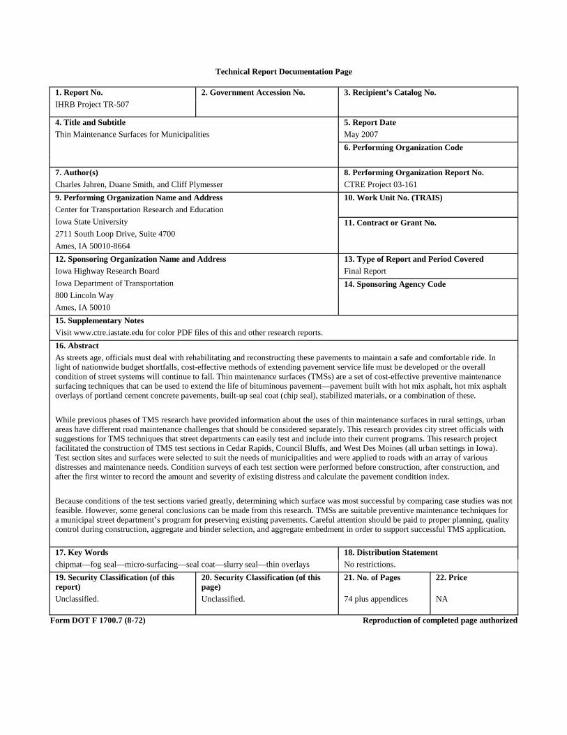