Embed Size (px)
Citation preview

Timers and Interrupts Shivendu Bhushan
Summer Camp ‘13

Recap
MCUA small computer integrated in a single IC
Has I/O, RAM and Memory

Software used CVAVR AVR Studio

Registers DDR PORT
PIN

Timers
t = 0T 0 0 0 0 0 0 0 0 t = 1T 0 0 0 0 0 0 0 1t = 2T 0 0 0 0 0 0 1 0t = 255T 1 1 1 1 1 1 1 1t = 256T 0 0 0 0 0 0 0 0
• 8-bit register.• Values starts from 0 and goes up to 255. Timer value increases by 1,after
each period.
• When the timer reaches its maximum value, in the next cycle, its value becomes 0 again and the process repeats itself.• The timer frequency can be factors of the base frequency of the MCU.• This process is independent of the CPU.

Simple Statistics• Maximum value of timer is n and clock period is t, then:
1. Timer period = t2. Timer cycle period = ( +1)×𝑛 𝑡3. Frequency of timer (f) = 1/𝑡4. Frequency of timer cycle = 1/( +1)×𝑛 𝑡

Suppose you need to check for a condition A while running another condition B
while(1){---- -> if (Event A == true)---- -> // print event A has occurred------------ -> Event B--------}
Do you see the problem in this approach??
-> Suppose Event A happens here

A better Solution: Interrupt• Interrupts means causing a break in a continuing process.• We execute the Event B in a normal while(1) loop.
. while(1){ --- --- EVENT B --- --- } .
• We will consider the occurrence of event A as an interrupt

Interrupts.while(1){------EVENT B------}.handleA(){.---}
We execute the required code in handler of event A
// print event A has occurred

More on Interrupts
• Interrupts are special events that can “interrupt” the normal flow of a program.• Whenever an Interrupt is called, the processor stops the normal
program, handles the interrupt, and then resumes its normal work.• There are two types of interrupts:
1. External2. Internal

External Interrupts• The controller monitors the input at the special pins INT0 and INT1,
whenever external interrupt is set on.• We can configure the program to call an external interrupt whenever
any of the following conditions are met.• Rising Edge• Falling Edge• Any change• Low level

Internal Interrupts
• The internal interrupts are called when different specific conditions are met by the timer value.• Timers can generate certain interrupts: two, to be precise.• These are called OVERFLOW interrupt and COMPARE MATCH
interrupt.

Overflow interrupts• An overflow interrupt is generated when the timer exceeds its
maximum value and resets to 0.• The interrupt may or may not have a handler. In either case, the timer
continues to run; remember: timers are independent of the CPU.• Suppose a timer of maximum value n has a time period t (also called
as clock period).• Then : 1. Timer cycle frequency = 1/( +1)×𝑛 𝑡 2. OVERFLOW interrupt frequency = 1/( +1)×𝑛 𝑡• If OVERFLOW interrupt is enabled, then an interrupt is generated in
every cycle.

Compare Match Interrupt• A compare match interrupt is called when the value of the timer equals a
specific value, set by the user.• This value is set by setting the value of OCR register.• Before incrementing, the value of the timer is compared to OCR. If the two
are equal, a COMPARE MATCH interrupt is generated.• Suppose a timer of maximum value n has a time period t (also called as
clock period). Then : 1. Timer cycle frequency = 1/( +1)×𝑛 𝑡 2. COMPARE MATCH interrupt frequency = 1/( +1)×𝑛 𝑡• If COMPARE MATCH interrupt is enabled, then an interrupt is generated in
every cycle.

Interrupts: Overflow and Compare Match

Timer modes
• A timer works in three modes: Normal, CTC and PWM.
• All three modes differ in the response of the controller to the interrupts generated.

Normal Mode• Standard mode: Timer starts at 0, goes to maximum value and then
resets itself.
• OVERFLOW and COMPARE MATCH interrupts generated as normal.

CTC Mode• Known as Clear Timer on Compare.
• As evident by the name, the timer starts at 0 as usual, but instead of resetting after maximum value, it resets after reaching value specified in OCR register.
• Compare match interrupt if enabled will be generated but not overflow interrupt (Why?)

CTC mode statistics• If clock time period is t: 1. Timer cycle time period = ( +1)×𝑂𝐶𝑅 𝑡 2. Frequency = 1/( +1)×𝑂𝐶𝑅 𝑡• With the use of CTC Mode we can theoretically generate any
frequency up to 8 MHz.
• Example : 1 Hz generation.

PWM mode• Known as Pulse Width Modulation• Simple method of obtaining analog output of any value between 0
and 5V.• Suppose we need 3V for our device at a specified pin. We supply 5V
on it for (3/5)* 100 % = 60% of the time period and 0V for the remaining time period.• The average voltage at the pin for a time period becomes 3V• If this step is repeated very fast (T is very small), then the output
behaves as a analog signal of 3V.

3.75 V 0.625 V

PWM mode• This “analog” value is obtained using timers.• A specific pin is set as output. When the timer reaches 0, the voltage
of the pin is set to 5V.• When the timer reaches the value specified by OCR, on the next
clock, the pin voltage is set to 0 until the timer resets itself.
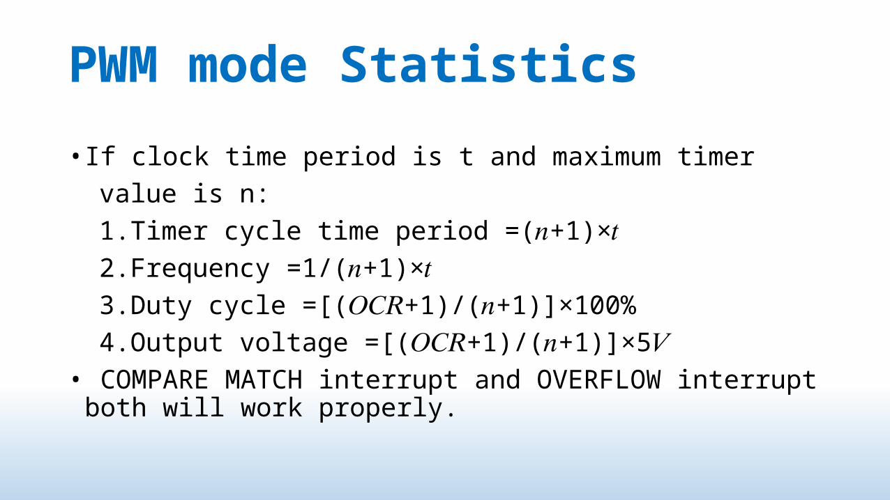
PWM mode Statistics
• If clock time period is t and maximum timer value is n: 1.Timer cycle time period =( +1)×𝑛 𝑡 2.Frequency =1/( +1)×𝑛 𝑡 3.Duty cycle =[( +1)/( +1)]×100%𝑂𝐶𝑅 𝑛 4.Output voltage =[( +1)/( +1)]×5𝑂𝐶𝑅 𝑛 𝑉• COMPARE MATCH interrupt and OVERFLOW interrupt both will work
properly.