Embed Size (px)
Citation preview
Tire Pressure Systems – Confidence Report
Aug-13 NACFE Page 1
Tire Pressure Systems
Report of a study conducted by the North American Council for Freight Efficiency on the Confidence of Adopting Tire Pressure Systems
August 15, 2013
© 2013 North American Council for Freight Efficiency. All rights reserved.
The contents of this document are provided for informational purposes only and do not constitute an endorsement of any product, service, industry practice, service provider, manufacturer, or manufacturing process. Nothing contained herein is intended to constitute legal, tax, or accounting advice, and NACFE assumes no liability for use of the report contents. No portion of this report or accompanying materials may be copied, reproduced or distributed in any manner without express attribution to the North American Council for Freight Efficiency.
Tire Pressure Systems – Confidence Report
Aug-13 NACFE Page 2
Acknowledgements
Study Team: Janelle Liechty, NACFE Program Analyst
Susan Nelson, Blue Stripe Scientific LLC, NACFE Program Manager Mike Roeth, NACFE Executive Director
Suzanne Slick, NACFE Senior Researcher External Advisor on Fleet Operations: Gary Cullen, Cullen Consulting Concepts LLC
Study Sponsors: Aperia Technologies Inc.
Bendix Commercial Vehicle Systems LLC Doran Manufacturing LLC
Frito-Lay North America Inc. Goodyear Tire & Rubber Company
Michelin North America Inc. P.S.I. Pressure Systems International
NACFE Technical Advisory Committee: Tim Dzojko, Air Products Allen Nielsen, CR England Mike O’Connell, Frito Lay
Scott Perry, Ryder Steve Phillips, Werner Enterprises Yves Provencher, FPInnovations
Mike Roeth, NACFE Executive Director Dale Spencer, UPS
Bruce Stockton, Stockton Solutions
Tire Pressure Systems – Confidence Report
Aug-13 NACFE Page 3
Table of Contents
List of Terms and Acronyms................................................................................................................ 5
List of Exhibits .................................................................................................................................... 6
Executive Summary ............................................................................................................................ 7
1.0 Introduction and Background ..................................................................................................... 11 1.1 Rationale for Study of Tire Pressure Systems ................................................................................... 11 1.2 Expected Performance Benefits and Industry Stakes ....................................................................... 12 1.3 Regulatory Perspectives for Tire Pressure Systems in Commercial Vehicle Applications ................ 15 1.4 Study Objectives ............................................................................................................................... 17
2.0 Study Approach .......................................................................................................................... 17
3.0 Description of Currently Available Tire Pressure Systems for Commercial Vehicles ....................... 19 3.1 Tire Pressure Monitoring Systems (TPMS) ....................................................................................... 21
3.1.1 Non-Transmitting Wheel-End Sensors ...................................................................................... 22 3.1.2 Transmitting Wheel-End Sensors .............................................................................................. 22
3.1.2.1 External Valve Stem Mounted/External Wheel Mounted Tire Pressure Monitors ..................................................................................................... 22
3.1.2.2 Internal Valve Stem Mounted/Internal Wheel Mounted/Tire Casing Mounted TPMS ................................................................................................................. 27
3.1.3 Pressure Sensing Mats .............................................................................................................. 31 3.1.4 Manual Tire Pressure Check Procedures in Fleets .................................................................... 32
3.2 Dual Tire Pressure Equalizer Systems ............................................................................................... 33 3.3 Automatic Tire Inflation Systems (ATIS) ........................................................................................... 34
3.3.1 ATIS Type 1 – Vehicle Tank Air Source ...................................................................................... 36 3.3.2 ATIS Type 2 – Direct Atmospheric Air Source with Self-Contained Pump ................................ 41
3.4 Central Tire Inflation Systems (CTIS) ................................................................................................ 45 3.5 Passive Pressure Containment Approaches ..................................................................................... 45
3.5.1 Nitrogen Inflation ...................................................................................................................... 45 3.5.2 Tires with Built-in Sealant Layer ................................................................................................ 46 3.5.3 Aftermarket Sealants ................................................................................................................ 47
4.0 Original Equipment Manufacturers’ Perspectives on Tire Pressure System Integration ................. 48 4.1 Trailer OEMs ..................................................................................................................................... 48 4.2 Tractor OEMs .................................................................................................................................... 49
5.0 Summary of Fleet Perspectives and Experiences with Current Tire Pressure Systems.................... 49
6.0 Tools – Technology Decision Matrix and Payback Calculator ........................................................ 53 6.1 Technology Decision Matrix ............................................................................................................. 53 6.2 Payback Calculator ............................................................................................................................ 54
7.0 Fleet Case Studies ....................................................................................................................... 56 7.1 Case Study 1: For-Hire Fleet Adopts ATIS for Trailer ........................................................................ 56 7.2 Case Study 2: Private Carrier Adopts TPMS for Tractor and Trailer ................................................. 59
8.0 Perspectives for Future Tire Pressure Systems ............................................................................. 61
Tire Pressure Systems – Confidence Report
Aug-13 NACFE Page 4
Table of Contents (continued)
9.0 Study Conclusions ...................................................................................................................... 64
References ....................................................................................................................................... 65
Appendix A: Product Summary Sheets for Selected Tire Pressure Technology Categories ................... 68
Appendix B: Expanded List of Tire Pressure Systems Suppliers .......................................................... 83
Appendix C: Contributing Systems Suppliers ..................................................................................... 88
Tire Pressure Systems – Confidence Report
Aug-13 NACFE Page 5
List of Terms and Acronyms
ACT – Americas Commercial Transportation Research Co. LLC ATA – American Trucking Associations ATIS – Automatic Tire Inflation System ATRI – American Transportation Research Institute BASIC – Behavior Analysis and Safety Improvement Category (part of CSA program) CAN – controller area network CFM – cubic feet per minute, measure of fluid flow rate CIP – cold inflation pressure CPM – cost per mile CSA – FMCSA Compliance, Safety, Accountability program CTIS – Central Tire Inflation System ECU – electronic control unit EPA – Environmental Protection Agency FMCSA – Federal Motor Carrier Safety Administration FMVSS – Federal Motor Vehicle Safety Standard GPO – Government Printing Office GVWR – gross vehicle weight rating LTL – For-hire less-than-truckload carrier NACFE – North American Council for Freight Efficiency NHTSA – National Highway Traffic Safety Administration NPTC – National Private Truck Council NTSB – National Transportation Safety Board OEM – original equipment manufacturer PSI – pounds per square inch, measure of pressure RF – radio frequency ROI – return on investment, reported in months needed to recover initial cost of acquisition SAE – SAE International, formerly Society of Automotive Engineers SMS – Safety Measurement System for CSA program online reporting TL – For-hire truckload carrier TMC – Technology & Maintenance Council TPMS – Tire Pressure Monitoring System
Tire Pressure Systems – Confidence Report
Aug-13 NACFE Page 6
List of Exhibits
Exhibit 1.1 Summary of Tire Pressure System Adoption Rates from NACFE 2013 Benchmark Study Exhibit 1.2 Summary of Federal Legislation Related to Tire Pressure Systems in Commercial Vehicles Exhibit 3.1 Classification of Tire Pressure System Technologies Exhibit 3.2 External Valve Stem/External Wheel Mounted TPMS (with Transceiver/Repeater) Exhibit 3.3 External Valve Stem/External Wheel Mounted TPMS (direct transmission to in-cab unit) Exhibit 3.4 Potential Risks Associated with Use of External Valve Stem/External Wheel Mounted TPMS Exhibit 3.5 Internal Valve Stem/Internal Wheel Mounted/Internal Tire Mounted TPMS Exhibit 3.6 Internal Valve Stem/Internal Wheel Mounted/Internal Tire Mounted TPMS:
Tractor-Trailer Configuration Exhibit 3.7 Potential Risks Associated with Use of Internal Valve Stem/Internal Wheel Mounted/
Internal Tire Casing Mounted TPMS Exhibit 3.8 Configuration of ATIS Type 1 – Vehicle Tank Air Source Exhibit 3.9 Potential Risks Associated with Use of ATIS Type 1 - Vehicle Tank Air Source Exhibit 3.10 Potential Risks Associated with Use of ATIS Type 2A – Direct Atmospheric Air Source Exhibit 5.1 Historical Rates of For-Hire Truckload Carrier Driver Turnover 2005-2012 Exhibit 5.2 Historical Rates of Private Carrier Driver Turnover 2005-2012 Exhibit 6.1 NACFE Tire Pressure System Technology Decision Matrix Exhibit 6.2 NACFE Tire Pressure Payback Calculator – Owner/Operator Exhibit 7.1 NACFE Tire Pressure Payback Calculator – For-Hire Fleet with Trailer ATIS Exhibit 7.2 NACFE Tire Pressure Payback Calculator – Private Fleet with TPMS on Tractor and Trailer
Tire Pressure Systems – Confidence Report
Aug-13 NACFE Page 7
Executive Summary
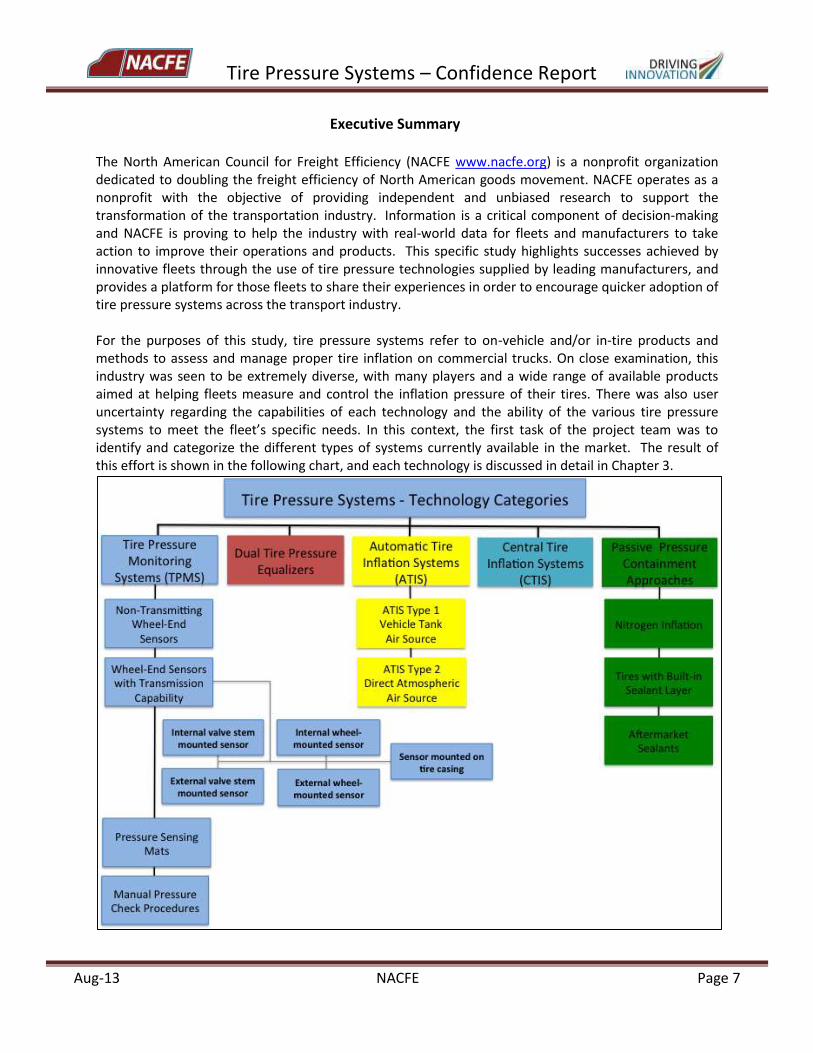
The North American Council for Freight Efficiency (NACFE www.nacfe.org) is a nonprofit organization dedicated to doubling the freight efficiency of North American goods movement. NACFE operates as a nonprofit with the objective of providing independent and unbiased research to support the transformation of the transportation industry. Information is a critical component of decision-making and NACFE is proving to help the industry with real-world data for fleets and manufacturers to take action to improve their operations and products. This specific study highlights successes achieved by innovative fleets through the use of tire pressure technologies supplied by leading manufacturers, and provides a platform for those fleets to share their experiences in order to encourage quicker adoption of tire pressure systems across the transport industry. For the purposes of this study, tire pressure systems refer to on-vehicle and/or in-tire products and methods to assess and manage proper tire inflation on commercial trucks. On close examination, this industry was seen to be extremely diverse, with many players and a wide range of available products aimed at helping fleets measure and control the inflation pressure of their tires. There was also user uncertainty regarding the capabilities of each technology and the ability of the various tire pressure systems to meet the fleet’s specific needs. In this context, the first task of the project team was to identify and categorize the different types of systems currently available in the market. The result of this effort is shown in the following chart, and each technology is discussed in detail in Chapter 3.
Tire Pressure Systems – Confidence Report
Aug-13 NACFE Page 8
Even though the categories shown above are all grouped under the umbrella of “tire pressure systems”, not every technology can address every type of tire inflation problem. Nor does every technology provide the same level of information to the user about the pressure condition of a specific tire. To help clarify performance capabilities by technology, the second task of the team was to identify a hierarchy of tire air losses, which could then be used to differentiate between commercial systems and also used to match fleet needs to product type. Excluding catastrophic air loss, which is judged to be outside the scope of the study, the general classes of tire air losses to be considered in the project are described below, listed in order of increasing severity.
Natural air diffusion or permeation through the casing.
Air seepage due to improper bead seating, a malfunctioning valve, or leaking valve seal.
Slow to moderate air leaks primarily due to small punctures.
Rapid air loss due to more significant punctures, but not including sudden, catastrophic air losses.
The approximate rate of air loss associated with each type of leak is presented in the report, based on documented natural air loss rates in tires as well as the reported pressure-loss detection capabilities of the various monitoring systems and, in the case of automatic inflation technologies, the air flow capacity which can be sustained by the system to overcome continuing inflation gas loss. It is hoped that future industry discussions will refine these categories of air loss in tires and the air flow rates associated with each leakage type. Tire pressure systems should be looked at in light of their capacity to address the different types of air loss in tires. For example, tire pressure monitoring systems (TPMS) cannot add air to an underinflated tire, but these systems provide the most extensive and flexible reporting of actual tire condition to the user, and are able to warn users about all the types of air losses that may be occurring. An automatic tire inflation system (ATIS) can restore air to tires, with different systems capable of handling different levels of underinflation, but such systems usually do not report the actual inflation pressure in any given tire. A less obvious example is the case of aftermarket sealants, which attempt to reduce the effect of air loss due to both air permeation and small punctures. Each system presents its own set of advantages and potential drawbacks. It is important for users to identify the type of tire inflation concern that has the most impact for their particular operations, and then choose the tire pressure technology that best tackles that type of problem. The NACFE project team reviewed a number of previously published studies from FMCSA and NHTSA on tire pressure system performance. These were studies comparing mainly dual tire pressure equalizers, sensor-based TPMS, and ATIS using air supplied by vehicle air tanks (Type 1). Both TPMS and ATIS were then evaluated in real-world field operational tests in fleets by FMCSA. The NACFE team was not able to identify any published or proprietary studies that compared the relative performance or reliability of any of the other technology categories/subcategories – for instance, pressure sensing mats versus TPMS, or aftermarket sealants versus dual tire equalizers. Thus, due to the wide variety of product attributes, functions and capabilities of each technology, and given that product testing was outside the scope of the NACFE project, there is no basis for ranking or rating the entire body of tire pressure technology categories. Future projects could focus on comparison of products within a given technology sub-
Tire Pressure Systems – Confidence Report
Aug-13 NACFE Page 9
category, that is, those products intended to yield the same functionality at generally similar price points. The FMCSA and NHTSA evaluations of dual tire pressure equalizers, sensor-based TPMS, and ATIS Type 1 demonstrated that all products function largely as designed by the manufacturers. Products that did not function well initially were significantly upgraded during the course of those studies, or are no longer on the market. Generally speaking, these three categories of today’s tire pressure products are expected to perform well in the field based on these results. In contrast, NACFE project team Internet surveys and interviews with fleets, who generally expressed positive opinions towards tire pressure systems, indicated somewhat mixed feelings about system reliability and payback. Certain fleets had favorable results with their adopted technologies, while other fleets had tried and abandoned the same technology. It is the feeling of the NACFE team that this gap between the results of controlled testing versus some fleet experiences can perhaps be explained by how well a fleet has matched their needs to the actual capabilities of a specific tire pressure system, and the amount of preparation a fleet is willing to go through to ensure successful adoption of a new technology. For example, 100% of the fleets surveyed by NACFE indicated that they had updated their routine or preventive maintenance plans to include inspections of their tire pressure systems, and 2/3rds had added a training program for their maintenance teams on the use of the equipment. Factors contributing to a satisfactory operation of tire pressure systems include:
The precondition for fleets to match their needs with the specific capabilities of the various tire pressure systems when making purchase decisions.
The importance of user readiness, in terms of personnel training and preparation of internal operating procedures around new tire pressure systems, to ensure successful deployment in the fleet.
The need for the functionality of tire pressure systems (alerts, warnings, data reporting) to integrate relatively seamlessly into normal, day-to-day fleet operations without requiring significant system oversight or maintenance by the fleet.
NACFE has put together the following tools and information in the report to help support the development of a good decision-making process for the purchase of various tire pressure technologies.
1. Risks of Technology Adoption. For sensor-based TPMS and ATIS, NACFE has created a table of potential operational risks associated with the products. This should not discourage any user from adopting a particular product, but instead is intended to be used in fleet internal discussions of their readiness to accept a new technology. High-level risks are summarized for the other categories of products. These tables are included in Chapter 3.
2. Tire Pressure Technology Decision Matrix. This tool identifies the major attributes of the
various tire pressure technology types in a single chart. End users, tire pressure systems manufacturers, tractor and trailer builders and others can select specific systems of interest and compare the characteristics of the various technologies. A description of this matrix is found in Chapter 6, and the tool will ultimately be available from the NACFE web site. This
Tire Pressure Systems – Confidence Report
Aug-13 NACFE Page 10
tool is meant to condense the immense amount of information obtained during this study effort into a single matrix that can assist in the choice of various technology types for specific fleet operations.
3. Payback Calculator. The NACFE calculator uses data from various published sources,
including the Federal Motor Carrier Safety Administration, the Technology and Maintenance Council, tire manufacturers, fleets, the tire pressure systems suppliers, tractor and trailer manufacturers and others. It calculates a simple payback in terms of roadside breakdowns, tire wear and fuel economy cost reductions given the use of the vehicles and data supplied by the fleet. Users may evaluate tractor-only, trailer-only, and tractor-plus-trailer fitments. It is a balanced and straightforward tool to be used by stakeholders in the industry to show the general economics for tire pressure system adoption. The payback calculator tool is described in Chapter 6, and will also be available from the NACFE web site. Although the tool is aimed at TPMS and ATIS technologies, a fleet with appropriate information could conceivably apply the tool to any tire pressure system or methodology.
4. Case Studies. Based on fleet interviews, representative case studies were developed for a
For-Hire fleet installing trailer ATIS (Type 1) and a Private Carrier adopting TPMS on both tractors and trailers. Time to achieve payback using the NACFE calculator is in the range of 9-14 months for these two case studies.
5. Product Summary Sheets. Product summary sheets were developed for seven TPMS and
five ATIS products and are included in Appendix A of this report. Each page contains a brief description of the system, product details such as alert levels, procurement options, and distinctive features. The appearance, or lack thereof, of an individual commercial product in this Appendix is not an indication of its performance, quality, functionality, or of any endorsement or recommendation by NACFE. NACFE does not endorse products or manufacturers. Products were chosen based on several factors: level of reported use by fleets and OEMs; the extent to which a particular product is characteristic of a category of tire pressure systems; and whether the product offers one or more unique features in its configuration, functionality, or technical approach.
6. Expanded List of Products and Systems Suppliers. An expanded list of commercially available tire pressure systems by category, including primary attributes and company contact information, is included in Appendix B. Five tire pressure technology categories and over 30 products are cited in this table. This list is not considered to be all-inclusive, given the potential for rapid turnover of products in the market.
As adoption of tire pressure technologies expands in the industry, it is expected that creative solutions will continue to be developed with improved performance, even better reliability, greater functionality, overall lower cost, and probably greater standardization, and will help sustain improvements in the efficiency and reliability of North American commercial freight transport.
Tire Pressure Systems – Confidence Report
Aug-13 NACFE Page 11
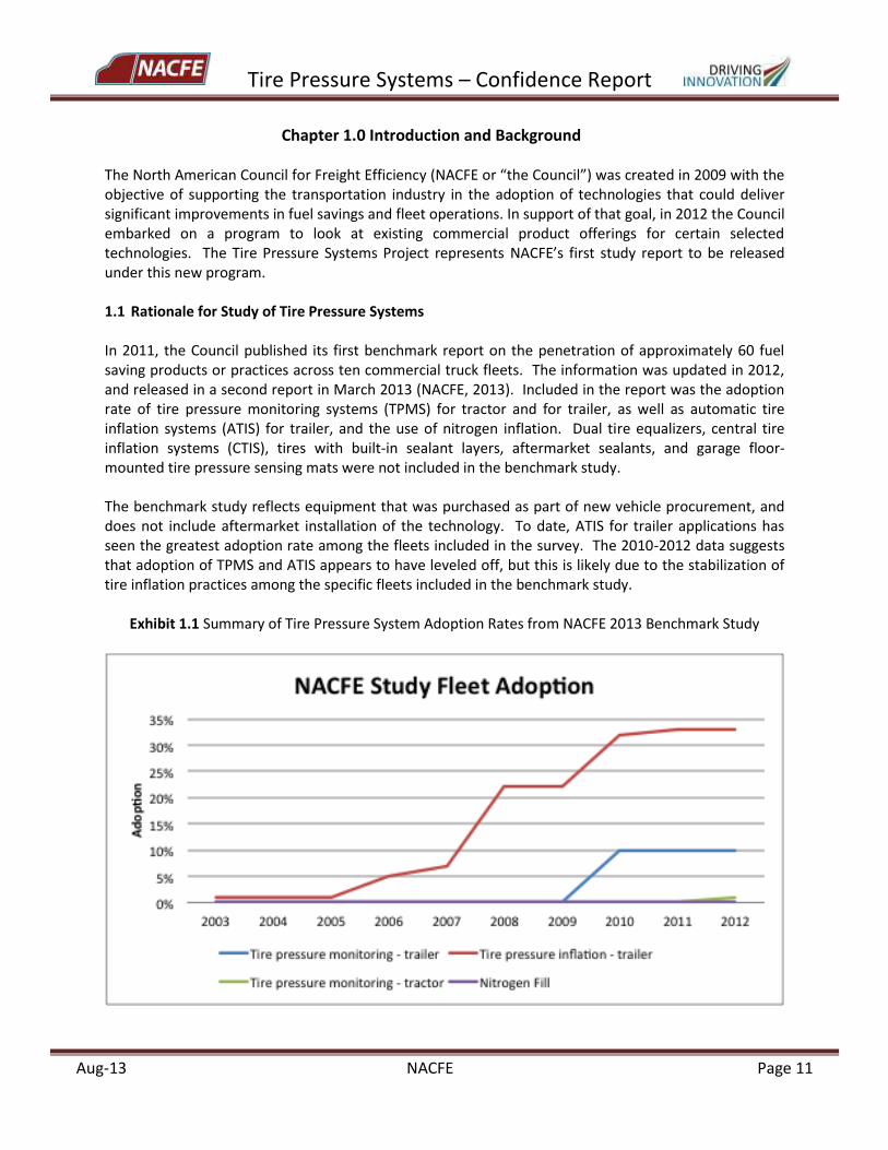
Chapter 1.0 Introduction and Background The North American Council for Freight Efficiency (NACFE or “the Council”) was created in 2009 with the objective of supporting the transportation industry in the adoption of technologies that could deliver significant improvements in fuel savings and fleet operations. In support of that goal, in 2012 the Council embarked on a program to look at existing commercial product offerings for certain selected technologies. The Tire Pressure Systems Project represents NACFE’s first study report to be released under this new program. 1.1 Rationale for Study of Tire Pressure Systems In 2011, the Council published its first benchmark report on the penetration of approximately 60 fuel saving products or practices across ten commercial truck fleets. The information was updated in 2012, and released in a second report in March 2013 (NACFE, 2013). Included in the report was the adoption rate of tire pressure monitoring systems (TPMS) for tractor and for trailer, as well as automatic tire inflation systems (ATIS) for trailer, and the use of nitrogen inflation. Dual tire equalizers, central tire inflation systems (CTIS), tires with built-in sealant layers, aftermarket sealants, and garage floor-mounted tire pressure sensing mats were not included in the benchmark study. The benchmark study reflects equipment that was purchased as part of new vehicle procurement, and does not include aftermarket installation of the technology. To date, ATIS for trailer applications has seen the greatest adoption rate among the fleets included in the survey. The 2010-2012 data suggests that adoption of TPMS and ATIS appears to have leveled off, but this is likely due to the stabilization of tire inflation practices among the specific fleets included in the benchmark study.
Exhibit 1.1 Summary of Tire Pressure System Adoption Rates from NACFE 2013 Benchmark Study
Tire Pressure Systems – Confidence Report
Aug-13 NACFE Page 12
After a review of the study results, the NACFE Board of Directors and Technical Advisory Committee approved a more detailed study with specific focus on tire pressure systems, to improve the level of information available on existing commercial systems and to identify fleet practices that would increase the success of tire pressure system implementation. 1.2 Expected Performance Benefits and Industry Stakes All industry stakeholders, including fleets, technical trade associations, tire pressure systems suppliers, original equipment manufacturers, tire manufacturers, and government administrators, agree on the importance of proper tire inflation to ensure safe and reliable fleet operations, and to achieve the greatest benefit and longest life from existing fleet assets. Benefits of Proper Tire Inflation Correct tire inflation, within the design limits of load and speed, reduces the risk of unexpected vehicle breakdown and damage, and promotes on-time freight delivery. Maintaining proper tire inflation level contributes to improved fuel efficiency, reduced tire wear, and longer casing life (FMCSA, 2003; TMC, 2012; Bridgestone 2008; Goodyear 2003; Michelin 2011). Reported impacts of tire underinflation include approximately 5-12% degradation in tire wear for an individual tire which is 10 psi underinflated, and 0.5-1.0% increase in fuel consumption (degradation in fuel economy) for a vehicle running with all tires underinflated by 10 psi. Greater fleet productivity and protection of fleet assets can be obtained through effective tire inflation pressure management. Historical payback estimates for the implementation of tire pressure systems have ranged from less than 1 year up to about 3 years, with annual savings projected at $750 to over $1000 per vehicle per year. Extent of Tire Underinflation in Commercial Vehicles In 2003, the Federal Motor Carrier Safety Administration reported the results of a widespread data collection effort to document actual tire pressures on trucks during their normal operations (FMCSA, 2003). The study collected data from more than 3200 tractors and straight trucks, and from 1300 trailers across For-Hire TL and LTL operators, Private Carriers, and Owner-Operators. Some of the results reported in the study, and often cited across the industry, are listed below:
About 1 out of 5 tractors/trucks is operating with 1 or more tires underinflated by at least 20 psi.
In addition, about 1 in 5 trailers is operating with 1 or more tires underinflated by at least 20 psi.
Nearly 3.5% of all tractors/trucks operate with 4 or more tires underinflated by at least 20 psi.
In addition, 3% of all trailers operate with 4 or more tires underinflated by at least 20 psi.
Approximately 3% of all trailers, and more than 3% of all tractors/trucks, are operating with at least 1 tire underinflated by 50 psi or more.
Only 46% of all tractor tires and 38% of all trailer tires inspected were within +/- 5 psi of the target pressure.
Tire Pressure Systems – Confidence Report
Aug-13 NACFE Page 13
To put this in perspective, the Technology & Maintenance Council of the ATA states that any tire found to be inflated to less than 80% of the fleet target pressure should be considered flat and immediately pulled from service for inspection (TMC 2012). For example, this would correspond to a condition of 80 psi in a tire operating in a fleet that has set a target pressure of 100 psi. The above results of the FMCSA 2003 study indicate that, while not typical, it was not unusual for an average vehicle to be operating with a tire in a potentially unsafe condition. However, at the time the FMCSA study was completed, neither the use of wide-base single tires in place of duals nor the use of any tire pressure monitoring or maintenance systems mounted on the vehicle were common occurrences. It would be beneficial to repeat a data collection effort of this type today, with the expectation that greater awareness of the importance of proper tire pressure, increased regulatory requirements for vehicle maintenance, and the wider use of tire pressure monitoring and maintenance equipment has resulted in much better management of tire inflation levels across the industry. Basics of Proper Tire Inflation Load-Inflation tables provided by all tire manufacturers inform users on the proper inflation of their tires. For each tire model, the tables designate both the maximum load that the tire is capable of supporting and the maximum inflation pressure, which is the amount of pressure needed in order for the tire to carry the maximum load. The tables also recommend the required minimum inflation pressure for loads that are less than the maximum. Generally, the required minimum inflation level is set to ensure that the tire will not be operated under low-pressure conditions that could compromise the life of the casing. A fleet that is running tire loads that are less than the maximum indicated in the load-inflation tables therefore has some level of choice of operating pressure. The tire must be inflated to at least the required minimum inflation pressure for a given load, but can feasibly be inflated to any level up to the maximum inflation pressure. The target pressure selected by the fleet depends on the point where the best performance is observed – not just for wear, but also for braking, handling, ride comfort, stability, and fuel consumption. Fleets that have been in business for some period of time will usually come to identify a level of tire inflation which offers optimum performance for tire wear, fuel consumption, and low maintenance, and which gives satisfactory vehicle performance for drivers. This may represent a single inflation pressure across steer, drive, and trailer tires, or may be a separate inflation pressure for each tire application. These levels will then be established as target inflation pressures for the fleet, often referred to as cold inflation pressures (CIP), meaning the pressure(s) the tires should be inflated to before the vehicle starts driving, normally in the morning when air temperatures are cool (ideally 65oF – 70oF). This optimum tire pressure depends on many variables, including equipment, routes, loads, and average environmental conditions for the fleet. For these reasons, the “best” tire pressure can be different from fleet to fleet. Even once a fleet has established its target tire inflation levels, and implemented a disciplined manual pressure check procedure as recommended by the tire supplier, it must overcome additional complications in ensuring optimal inflation levels. Tire inflation pressures begin to evolve the minute a vehicle starts rolling. For example, if the surrounding air gets warmer, inflation pressure increases. If the air gets cooler, inflation pressure decreases. The tire itself warms up as it starts rolling, increasing the pressure, while if the vehicle stops for breaks or overnight parking, the pressure usually decreases due to tire cooling. If the load increases the tire pressure can also increase (due to more flexing and heating of the tire).
Tire Pressure Systems – Confidence Report
Aug-13 NACFE Page 14
Fleets live with this tire pressure variation every day, and establish target pressures that, on average, give them the best performance for their tires and vehicles. To maintain safety and durability, a fleet would never want to use a cold inflation pressure which is lower than the required minimum tire inflation pressure as defined by the manufacturer. However, a fleet may want to explore how tire pressures fluctuate during a normal day, and whether operations can be improved by modifying existing strategies to maintain inflation pressure. Along with any existing strategies a fleet may have in place, the market today offers a wide range of tire pressure systems which work to overcome one or more of the primary causes of tire underinflation (FMCSA, 2007; NHTSA, 2010; Park, 2013):
Natural air loss due to diffusion through the tire casing, estimated at up to 2 psi per month (at normal tire operating pressures of around 100 psi).
Air seepage due to a malfunctioning valve, leaking valve seals, or improper bead seating, up to approximately 2 psi per week to 2 psi per day.
Slow to moderate leaks primarily due to small punctures (but may also be caused by valve or bead seat irregularities), up to the range of about 5 psi per hour.
Rapid air loss, at rates of approximately 1-5 psi per minute or higher.
Sudden, catastrophic air loss is not included as a condition that can be addressed by tire pressure systems and is outside the scope of this study. Different systems are designed to report and/or correct for one or more of the conditions above. Physical testing is outside the scope of this study, and the NACFE team has had to rely on previously reported test results of tire pressure system accuracy and reliability. Short term track testing of dual tire equalizers, TPMS, and ATIS products has shown that all of the evaluated products perform correctly in response to underinflated tires (FMCSA, 2007; NHTSA 2010). However, a one-year long field evaluation of several TPMS products in a city transit bus fleet (FMCSA, 2009) demonstrated the importance of training and preparation of fleet personnel for proper installation, use, and interpretation of TPMS components in order to achieve a successful implementation of new equipment. In this context, three key themes of this report are:
The precondition for fleets to match their needs with the specific capabilities of the various tire pressure systems when making purchase decisions.
The importance of user readiness, in terms of personnel training and preparation of internal operating procedures around new tire pressure systems, to ensure successful deployment in the fleet.
The need for the functionality of tire pressure systems (alerts, warnings, data reporting) to integrate relatively seamlessly into normal, day-to-day fleet operations without requiring significant system oversight or maintenance by the fleet.
A few examples illustrate the importance of these three points. For instance, an automatic tire inflation system will work to re-inflate a tire that has a lower pressure than the pre-set target of the inflation system, without adjustment for the tire temperature. That system will turn off once the combination of
Tire Pressure Systems – Confidence Report
Aug-13 NACFE Page 15
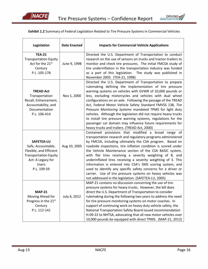
re-inflation and tire warming brings the pressure to the target level. Track testing of re-inflation response times of ATIS have shown that a tire can be returned to its proper pressure within 1-10 minutes of the start of system operation, even for initial conditions of 20-30 psi underinflation (FMCSA, 2007; NHTSA 2010). Since the re-inflation cycle occurs rapidly, a tire will continue to increase in temperature and inflation pressure while driving, and may eventually exceed the target pressure. Only some ATIS will allow air to be released once a tire exceeds its target inflation by a certain level. Moreover, depending on set points of the systems, a tire may drop below the target pressure level as it goes through cooling when the vehicle is parked. A fleet must determine the best target pressure to select in light of these fluctuations. In addition, the fleet should consider the risk it is willing to accept in the event that an ATIS is able to mask the condition of a slowly leaking tire. As another example, tire pressure can increase by 10-15% due to the effects of warm-up (TMC, 2012), which will be detected with TPMS. But most TPMS options do not include temperature compensation for increased pressure due to tire heating, making it possible for the system to issue a low pressure alert at the start of driving only to switch off the alert once the warm tire pressure exceeds the warning threshold. In contrast, TPMS with temperature compensation would indicate that the tire is underinflated even as the pressure in the tire rises in this case. From the user point of view, a fleet should determine in advance if this tire inflation situation is considered a false positive (e.g., the system gave a warning when pressure was in fact acceptable), or if it should be treated as an underinflation condition to be corrected immediately. For either of the above example cases, as well as for other tire pressure technologies, the user must establish the operating guidelines for operators and maintenance personnel, especially in response to pressure alerts, in order to make effective use of tire pressure systems. 1.3 Regulatory Perspectives for Tire Pressure Systems in Commercial Vehicle Applications Legislation Related to Use of Tire Pressure Systems on Heavy Vehicles As of the writing of this report there were no regulatory requirements regarding the use of any tire pressure system on commercial vehicles with GVRW greater than 10,000 pounds. However, there have been four key pieces of legislation enacted over the past 15 years that may influence the future approach of regulators to the topic of tire pressure systems, particularly TPMS, in commercial vehicle applications. The mandates of these bills and the primary impacts for commercial vehicle pressure systems are summarized in the following table.
Tire Pressure Systems – Confidence Report
Aug-13 NACFE Page 16
Exhibit 1.2 Summary of Federal Legislation Related to Tire Pressure Systems in Commercial Vehicles
Legislation
Date Enacted
Impacts for Commercial Vehicle Applications
TEA-21 Transportation Equity
Act for the 21st Century
P.L .105-178
June 9, 1998
Directed the U.S. Department of Transportation to conduct research on the use of sensors on trucks and tractor-trailers to monitor and check tire pressures. The initial FMCSA study of tire underinflation in the transportation industry was funded as a part of this legislation. The study was published in November 2003. (TEA-21, 1998)
TREAD Act Transportation
Recall, Enhancement, Accountability, and
Documentation P.L. 106-414
Nov 1, 2000
Directed the U.S. Department of Transportation to prepare rulemaking defining the implementation of tire pressure warning systems on vehicles with GVWR of 10,000 pounds or less, excluding motorcycles and vehicles with dual wheel configurations on an axle. Following the passage of the TREAD Act, Federal Motor Vehicle Safety Standard FMVSS 138, Tire Pressure Monitoring Systems mandated TPMS for light duty vehicles. Although the legislation did not require heavy trucks to install tire pressure warning systems, regulations for the passenger car domain may influence future requirements for heavy trucks and trailers. (TREAD Act, 2000)
SAFETEA-LU Safe, Accountable,
Flexible, and Efficient Transportation Equity
Act: A Legacy for Users
P.L. 109-59
Aug 10, 2005
Contained provisions that modified a broad range of transportation research and regulatory programs administered by FMCSA, including ultimately the CSA program. Based on roadside inspections, tire inflation condition is scored under the Vehicle Maintenance section of the CSA BASIC system, with flat tires receiving a severity weighting of 8, and underinflated tires receiving a severity weighting of 3. This information is entered into CSA’s SMS scoring system, and used to identify any specific safety concerns for a driver or carrier. Use of tire pressure systems on heavy vehicles was not addressed in the legislation. (SAFETEA-LU, 2005)
MAP-21 Moving Ahead for
Progress in the 21st Century
P.L. 112-141
July 6, 2012
MAP-21 contains no discussion concerning the use of tire pressure systems for heavy trucks. However, the bill does direct the U.S. Department of Transportation to consider rulemaking during the following two years to address the need for tire pressure monitoring systems on motor coaches. In support of continuing work on heavy duty vehicle safety, the National Transportation Safety Board issued recommendation H-09-22 to NHTSA, advocating that all new motor vehicles over 10,000 pounds be equipped with direct TPMS. (MAP-21, 2012)
Tire Pressure Systems – Confidence Report
Aug-13 NACFE Page 17
EPA SmartWay program The EPA SmartWay Transport program is a partnership between government and transportation industry members to voluntarily seek solutions to reduce emissions and improve fuel efficiency of freight transport. As one part of the program the EPA verifies the fuel savings and environmental performance of a range of equipment and practices that are offered to commercial fleets, with the goal of assisting fleets in making informed purchase decisions about new technologies, both in terms of the effectiveness of the technology as well as the payback. By providing this information the program aims to facilitate the voluntary adoption of new solutions to reduce fuel consumption and lower environmental impacts. The SmartWay Transport program has specifically recognized the importance of proper tire inflation as a means to reduce air pollution and at the same time yield monetary benefits to the fleets. 1.4 Study Objectives The overall objectives of this study include:
A synthesis of commercially available tire pressure monitoring and maintenance systems and their features.
An exploration of the potential benefits and challenges for fleets related to system implementation.
Examples of fleet experiences with systems that have been tested or are in use.
Recommendations/guidelines for selecting and incorporating tire pressure systems into fleet operations.
Data is compiled from technical reports published by academia and government agencies, product information on websites and in industry publications, and direct interviews with stakeholders representing tire pressure system suppliers, original equipment tractor and trailer manufacturers, and fleet maintenance and operations managers. Testing of tire pressure systems is not included in the scope of the project. This report is intended to collect and share information in order to support fleet technology choices, as well as to discuss current trends and equipment needs that can serve as inputs for designers of future systems.
Chapter 2.0 Study Approach
The approach taken by the project team during the period of the study is described in the following tasks:
Initial literature review to identify and categorize types of systems for controlling tire inflation
pressure in heavy-duty trucks and trailers.
Online research on the commercially available systems in each category. These first two steps resulted in the initial identification of 8 categories and approximately 40+ potential suppliers of tire pressure systems. It became evident that the business of heavy vehicle tire pressure
Tire Pressure Systems – Confidence Report
Aug-13 NACFE Page 18
systems is a very dynamic industry, with nearly continuous introduction of new products, combined with continuous exit of products and/or companies from the market.
Since a study of market-share-by-product was outside the scope of the NACFE Tire Pressure Systems project, fleets and OEMs were contacted to screen for market penetration of specific products. Because of the size or nature of these organizations, some tire pressure systems may be underrepresented or not present at all in their responses.
Specific tire pressure systems suppliers and products were selected for in-depth interviews about product capabilities, market presence and maturity, and distinctive product features. Products selected for this portion of the study were chosen based on several factors: level of reported use by fleets and OEMs; the extent to which a particular product is characteristic of a category of tire pressure systems; and whether the product offers one or more unique features in its configuration, functionality, or technical approach. All products selected for this treatment were required to be commercially available by the end of the first quarter of 2013.
Product summary sheets were developed for seven TPMS and five ATIS products and are included in Appendix A of this report. The appearance, or lack thereof, of an individual commercial product in this Appendix is not an indication of its performance, quality, functionality, or of any endorsement or recommendation by NACFE. NACFE does not endorse products or manufacturers. Individual products in each category can exhibit equivalent performance. An expanded list of tire pressure systems by category, including primary attributes and company contact information, is included in Appendix B. Ultimately, five major categories and over 30 products are cited in this report.
The scope of the NACFE Tire Pressure Systems Project did not include testing for the accuracy or durability of any tire inflation product. Instead, previous product evaluations for TPMS and ATIS that were reported by government testing organizations were reviewed by the NACFE team (FMCSA, 2007; FMCSA 2009; NHTSA 2010), which included both short term track testing and a yearlong field test of TPMS in one city transit bus fleet. With respect to the products on the market today, the evaluations conducted by the study team indicate that the intrinsic performance of all products conforms to the design and functionality specified by the manufacturers. Consequently, the NACFE has treated all systems as equally reliable and as providing equal benefit when properly used. Clearly, if the reliability of a given tire pressure system depends on fleet personnel correctly interpreting and responding to system alarms consistently, and they do not, a fleet is not going to realize the full potential benefits of the system.
Risk charts have been constructed by NACFE for the main TPMS and ATIS product categories. Fleets can use these charts to review their readiness for adoption of a specific technology as well as to develop their risk response plans for a selected product type.
Tire Pressure Systems – Confidence Report
Aug-13 NACFE Page 19
A Technology Decision Matrix was developed to identify the main characteristics and operational features of the various tire pressure system types.
An ROI or payback calculator was developed for this report that considers the factors of road service call reduction, reduced tire replacement cost for normal operations, and fuel economy improvements.
Finally, perspectives on new product features and capabilities were summarized from stakeholder interviews.
Chapter 3.0 Description of Currently Available Tire Pressure Systems for Commercial Vehicles Based on interviews with tire pressure systems suppliers, other NACFE-conducted fleet surveys, and a review of online information sources including industry standards and recommended practices, the team organized tire pressure system technologies into the categories shown in Exhibit 3.1. The major categories are:
1. Tire Pressure Monitoring Systems (TPMS). These systems provide a direct measurement of pressure, and, in some cases, temperature. The measured pressure is compared to a pre-set target pressure determined by the fleet user for a given vehicle wheel position. If the tire is underinflated, maintenance staff and the driver are alerted by either a static visual display at the wheel-end, or by the transmission of sensor data to an in-cab display or to a computer system that can be accessed by the fleet. The TPMS category includes mats or plates containing an array of sensors that pick up and transmit the loading conditions of the tire footprint as the tire rolls over the surface of the mat. The mats can be embedded in pavement or placed on the floor of a garage. In addition, fleet-wide manual tire pressure check procedures are included in this category. Most of these systems can also signal an overpressure condition. With the exception of the floor sensor mats, all systems included in this report are direct TPMS, that is, systems wherein pressure is measured directly and is not derived from other vehicle or tire parameters.
2. Dual Tire Pressure Equalizers. In these systems, a single sensor unit is mounted to the
vehicle wheel end, monitoring the pressure in both tires of a dual-tire assembly, with a hose connection to each tire valve stem. If pressure levels between the tires do not match, either due to temperature warming of one tire position versus the other, unequal loading, or slow air seepage, the system will attempt to bring the inflation pressure of the two tires to the same level. No air is added or removed from the dual assembly by the equalizer unit. If air loss continues, the leaking tire is isolated and a static visual display indicates the progressive loss of pressure.
3. Automatic Tire Inflation Systems (ATIS). These systems monitor tire inflation pressure
relative to a pre-set target and re-inflate tires whenever the detected pressure is below the target level. In general, these systems will alert the driver that re-inflation is taking place, but they do not report on the actual pressure in the tire. ATIS either rely on vehicle compressed-air tanks as an inflation medium source, or else draw air directly from the
Tire Pressure Systems – Confidence Report
Aug-13 NACFE Page 20
surrounding environment via a self-contained pump. Some ATIS equipment is capable of pressure relief for overinflated tires.
4. Central Tire Inflation Systems (CTIS). The operation of this type of system is similar to ATIS,
with the difference that the driver can select the target pressure from an in-cab display, in order to raise or lower the tire inflation level depending on the operating conditions of the vehicle. Most systems of this type are intended for off-road or military truck applications.
5. Passive Pressure Containment Approaches. Another category of technologies capable of
preventing tire pressure loss attempt to retain air in the tire once it has been inflated. These most commonly function by reducing natural air loss through the tire casing. However, certain products in this category can mitigate the effects of small punctures. Use of an inflation medium such as nitrogen that has a lower permeation rate than oxygen, and alternative means to providing barriers to air loss through the use of sealants, are represented in this category.
Exhibit 3.1 Classification of Tire Pressure System Technologies
Tire Pressure Systems – Confidence Report
Aug-13 NACFE Page 21
3.1 Tire Pressure Monitoring Systems (TPMS)
In this study, a tire pressure monitoring system or TPMS will be distinguished from an ATIS (automatic tire inflation system) and a CTIS (central tire inflation system) by the following features:
A TPMS monitors pressure and in some cases, temperature, for each individual tire. TPMS can identify underinflated tires by using a device that senses pressure and temperature and in most cases, transmits the data and displays it to the operator.
A TPMS monitors each tire based on a pre-set target pressure, and issues alerts based on the difference between the target pressure and the actual measured pressure in the tire.
Types of Tire Pressure Monitoring Systems Current TPM systems are separated into two fundamental types, depending on the positioning of the sensors:
External valve stem mounted/External wheel mounted tire pressure monitors. External valve stem mounted tire pressure monitors use sensors that are mounted to the end of the valve stem in place of the valve stem cap. The sensors monitor the air pressure of the tire and, in some systems, monitor the wheel end temperature. The sensors then transmit the data from the tire to a transceiver/repeater and on to an in-cab display. There are some systems that transmit directly from the sensors to an in-cab display. External wheel mounted tire pressure monitors use sensors that are mounted to the wheel. The sensors are mounted with a bracket and then hoses are run from the sensors to the valve stem. This subtype is then further broken down based on how the pressure data is displayed to the operator, as they may use either an in-cab display or may require a visual walk-around of the tractor/trailer by the operator. External TPMS can be used on tractor, trailer or in combination.
Internal valve stem mounted/Internal wheel mounted/Tire casing mounted tire pressure monitors. Internal valve stem mounted tire pressure monitors use sensors that are mounted internally at the base of the valve stem. The sensors monitor the air pressure and in some cases temperature. Internal wheel mounted tire pressure monitors use sensors that are mounted to the wheel with a band or strap. The sensors monitor both the air pressure and the temperature inside the tire envelope. Both of the above sensor types are either read by a receiver/transceiver or transmit their data to a receiving ECU/antenna. The signal is then transmitted to the in-cab display. The in-cab display will alert the driver, in real time, to any tire pressure loss or temperature increase. Some of these systems will also report corrected tire pressure derived from the tire’s internal temperature at the time. Tire casing mounted tire pressure monitors use a sensor mounted in the summit area of the tire. The sensor, inside a rubber container, is glued onto the tire casing. Each sensor monitors tire pressure and temperature. This data is sent from the sensor to the ECU antenna mounted on the tractor, and then transmitted to the in-cab display. The display will then alert the driver to any tire pressure or temperature event. Internal TPMS can be used on tractor, trailer or in combination.
Tire Pressure Systems – Confidence Report
Aug-13 NACFE Page 22
3.1.1 Non-Transmitting Wheel-End Sensors Non-transmitting wheel-end tire pressure monitors use sensors mounted to the end of the valve stem. This is the most basic type of TPMS because it does not transmit the tire pressure data. The sensor will simply provide a visual indication of the tire pressure, requiring the operator to do a “walk-around” of the tractor and trailer in order to see the tire pressure reading. This type can be used on tractor, trailer, or in combination. 3.1.2 Transmitting Wheel-End Sensors Two distinct advantages of TPMS of this type are that:
They obtain a direct measurement of the actual pressure for each individual tire that contains a sensor. The pressure condition for each tire is reported to the operator or to fleet maintenance personnel during both normal operating conditions as well as for pressure alerts. (As will be discussed later, ATIS installations will generally connect all tires to a central control unit, and a typical ATIS will not report actual pressure for individual tires or indicate which tire is experiencing a low-pressure issue.)
TPMS can link to existing vehicle communications networks to transmit tire pressure data and other tire condition information to Internet and cell phone systems. A fleet may choose to have the initial notification of a tire with low pressure sent to fleet maintenance personnel to determine what action should be taken, rather than to a driver. Data can be collected in central databases and analyzed for tire performance trends, and may also link to a fleet’s work order system for tire inspection and maintenance scheduling.
3.1.2.1 External Valve Stem Mounted/External Wheel Mounted Tire Pressure Monitors System Components Sensors. The sensors used in this type of TPMS are wireless. Each sensor is mounted on the valve stem in place of the valve stem cap or on the outside of the wheel with a mounting bracket. The sensors transmit tire information through an RF signal to the in-cab display, a hand-held tool, or a gate reader. Most suppliers offer a standard sensor and an industrial sensor for large bore valve stems. The sensor transmission distance may vary, but most suppliers claim up to 300 feet. The sensor weight varies with supplier, from 2/3 oz. to .83 oz. Each sensor contains an internal battery that cannot be recharged or replaced. The average battery life claimed by suppliers varies from 3 to 5+ years, (FMCSA, 2007; Interviews with Industry Stakeholders) depending on the frequency of monitoring and transmission of tire information. Transceiver. A transceiver is used to transmit data wirelessly from the sensors to an in-cab display. Not all systems employ transceivers. Intelligent Gateway/Repeater. Many TPMS include an intelligent gateway along with a repeater, which are used to accept a signal from the sensor and transfer it to the vehicle network. The gateway can be mounted inside or outside of the tractor, while the repeater is mounted outside of the trailer. The
Tire Pressure Systems – Confidence Report
Aug-13 NACFE Page 23
transmission of the signal is not done wirelessly, however, and will need power from the tractor to the gateway and from the tractor to the trailer for the repeater. The transmission distance capability may vary, but most suppliers claim a range of 100 feet to 1000 feet. Most repeaters can collect and transmit information for up to 16 tires. When a gateway is used with a repeater, the gateway can read up to 160 tires. Gateways and repeaters do not have operator interface capabilities. Instead, an in-cab display is used for sensor monitoring by the operator. In-Cab Display. The in-cab display is used as the interface between the operator and the tire sensors. The display enables the operator to monitor tire pressure and sometimes temperature of each tire. Most displays continuously monitor the tire pressure and temperature data transmitted from the wireless sensors. This data is then shown on the display in various forms from actual tire pressure readings, actual tire temperature readings, audible alerts (fast leak, low pressure, and high pressure), and visual symbols and flashing light alerts. The maximum number of wheel positions that can be displayed, and the display layout, vary from system to system. The in-cab display is either mounted in the instrument panel or to the bottom of the over-head console. Some systems require that the display be mounted near the windshield to enable satellite communication. Gate Reader. Gate readers are optional devices offered with some systems. They automatically collect tire data every time the tractor and trailer come into the yard. The gate reader could be mounted at various points in the yard, for example at the entrance/exit gate or at the fuel island. This data is then transmitted to internal software that the company maintains (or in some case to a web portal), where maintenance personnel can see the data and determine the best course of action. These devices may not be the best for long-haul fleets that are away from central terminals for long periods of time. Hand-Held Programming/Receiving Tool. Hand-held programming tools are optional devices that are offered with some systems. They can be used for programming each tire position and to wirelessly collect tire data. They are then used with internal software that the company maintains. A physical “walk around” of the vehicle is required for programming each sensor. This option may work best for small fleets. Tire Hoses. Tire hoses are used with some systems to connect the wheel-end mounted sensor to the tire valve stem. Most systems that use hoses also offer a quick fill port so the hose does not need to be removed from the tire valve stem in order to add air to the tire.
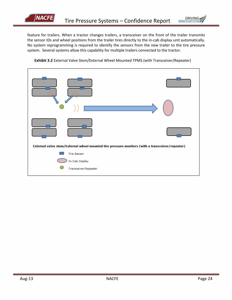
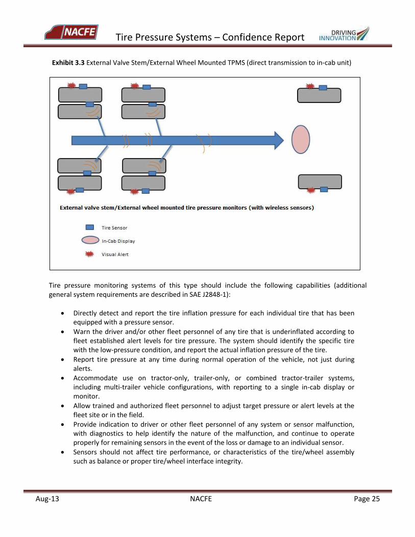
Overview of Functionality of External Valve Stem/External Wheel Mounted TPMS The following schematics (Exhibit 3.2 and Exhibit 3.3) show the basic functionality of an external valve stem/external wheel mounted TPMS system. As described earlier, each sensor is mounted either on the end of the valve stem or on the wheel-end itself. Each sensor detects the tire pressure and also, with some systems, tire temperature, and then wirelessly transmits this data to the transceiver/repeater, which will then send the signal to the in-cab display or else the sensors simply transmit the signal directly to the in-cab display. It is important to note that on some of these systems, tire temperature data represent the temperature measured at the wheel end and not the internal tire temperature. Systems that measure and compensate for internal tire temperature will be discussed in the next section. The signal is then received by the in-cab-display that will allow the operator to monitor the pressure and temperature of each tire position. Some of these systems also offer a ‘drop and hook’
Tire Pressure Systems – Confidence Report
Aug-13 NACFE Page 24
feature for trailers. When a tractor changes trailers, a transceiver on the front of the trailer transmits the sensor IDs and wheel positions from the trailer tires directly to the in-cab display unit automatically. No system reprogramming is required to identify the sensors from the new trailer to the tire pressure system. Several systems allow this capability for multiple trailers connected to the tractor.
Exhibit 3.2 External Valve Stem/External Wheel Mounted TPMS (with Transceiver/Repeater)
Tire Pressure Systems – Confidence Report
Aug-13 NACFE Page 25
Exhibit 3.3 External Valve Stem/External Wheel Mounted TPMS (direct transmission to in-cab unit)
Tire pressure monitoring systems of this type should include the following capabilities (additional general system requirements are described in SAE J2848-1):
Directly detect and report the tire inflation pressure for each individual tire that has been equipped with a pressure sensor.
Warn the driver and/or other fleet personnel of any tire that is underinflated according to fleet established alert levels for tire pressure. The system should identify the specific tire with the low-pressure condition, and report the actual inflation pressure of the tire.
Report tire pressure at any time during normal operation of the vehicle, not just during alerts.
Accommodate use on tractor-only, trailer-only, or combined tractor-trailer systems, including multi-trailer vehicle configurations, with reporting to a single in-cab display or monitor.
Allow trained and authorized fleet personnel to adjust target pressure or alert levels at the fleet site or in the field.
Provide indication to driver or other fleet personnel of any system or sensor malfunction, with diagnostics to help identify the nature of the malfunction, and continue to operate properly for remaining sensors in the event of the loss or damage to an individual sensor.
Sensors should not affect tire performance, or characteristics of the tire/wheel assembly such as balance or proper tire/wheel interface integrity.
Tire Pressure Systems – Confidence Report
Aug-13 NACFE Page 26
Sensors should function under all conditions normally encountered during vehicle operation, such as speed, ambient temperature, and vehicle maneuvers.
Optionally, the system may measure and report temperature, which could be used to determine overheating at a wheel-end location.
Optionally for systems connecting to the vehicle CAN, the system should respect the requirements for vehicle communications described in the SAE J1939/1 recommended practice.
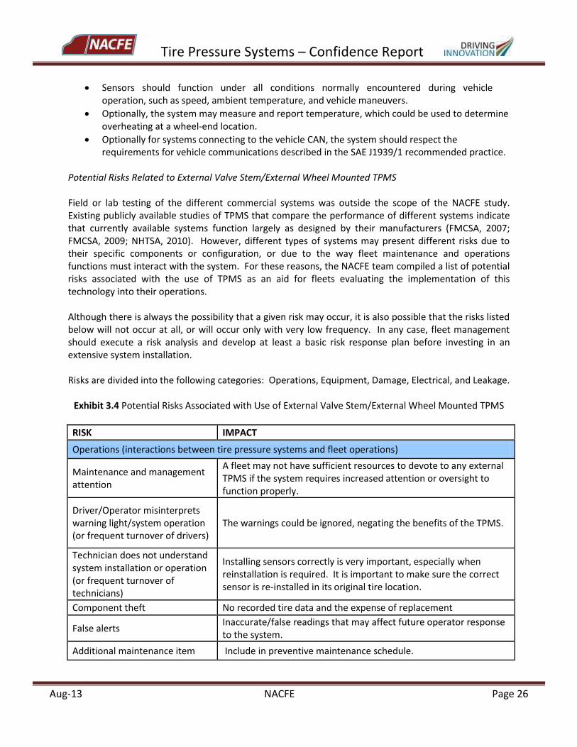
Potential Risks Related to External Valve Stem/External Wheel Mounted TPMS Field or lab testing of the different commercial systems was outside the scope of the NACFE study. Existing publicly available studies of TPMS that compare the performance of different systems indicate that currently available systems function largely as designed by their manufacturers (FMCSA, 2007; FMCSA, 2009; NHTSA, 2010). However, different types of systems may present different risks due to their specific components or configuration, or due to the way fleet maintenance and operations functions must interact with the system. For these reasons, the NACFE team compiled a list of potential risks associated with the use of TPMS as an aid for fleets evaluating the implementation of this technology into their operations. Although there is always the possibility that a given risk may occur, it is also possible that the risks listed below will not occur at all, or will occur only with very low frequency. In any case, fleet management should execute a risk analysis and develop at least a basic risk response plan before investing in an extensive system installation. Risks are divided into the following categories: Operations, Equipment, Damage, Electrical, and Leakage.
Exhibit 3.4 Potential Risks Associated with Use of External Valve Stem/External Wheel Mounted TPMS
RISK IMPACT
Operations (interactions between tire pressure systems and fleet operations)
Maintenance and management attention
A fleet may not have sufficient resources to devote to any external TPMS if the system requires increased attention or oversight to function properly.
Driver/Operator misinterprets warning light/system operation (or frequent turnover of drivers)
The warnings could be ignored, negating the benefits of the TPMS.
Technician does not understand system installation or operation (or frequent turnover of technicians)
Installing sensors correctly is very important, especially when reinstallation is required. It is important to make sure the correct sensor is re-installed in its original tire location.
Component theft No recorded tire data and the expense of replacement
False alerts Inaccurate/false readings that may affect future operator response to the system.
Additional maintenance item Include in preventive maintenance schedule.
Tire Pressure Systems – Confidence Report
Aug-13 NACFE Page 27
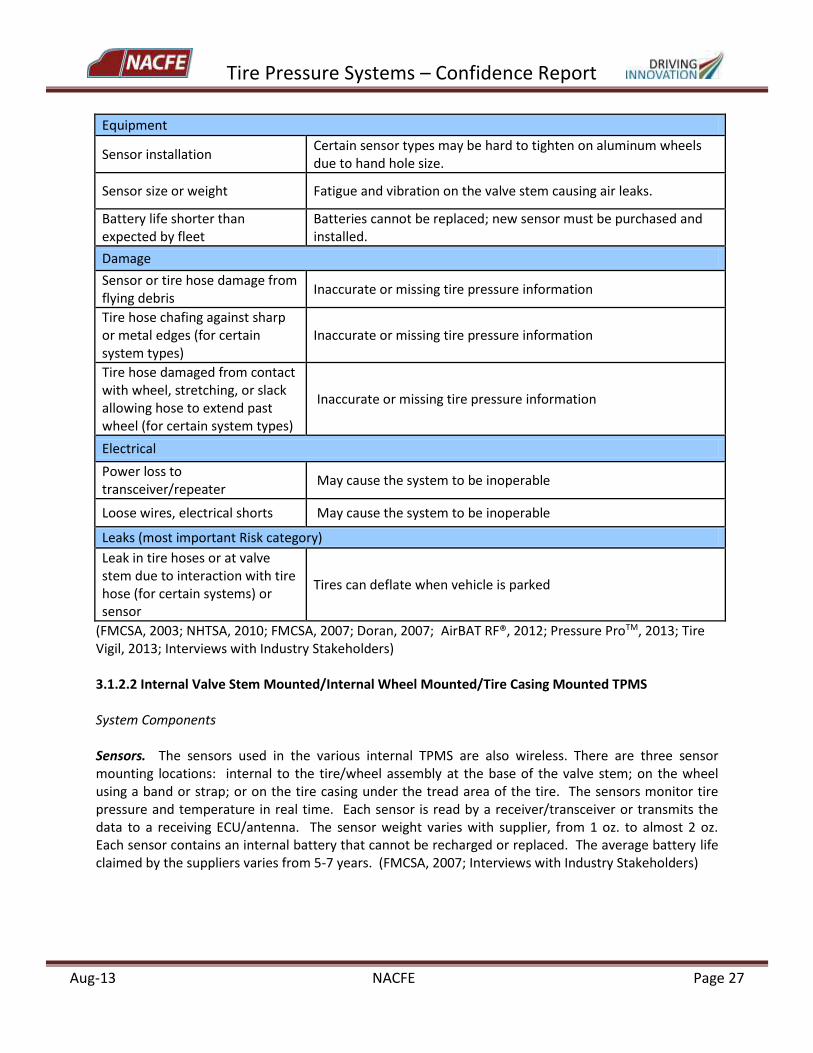
Equipment
Sensor installation Certain sensor types may be hard to tighten on aluminum wheels due to hand hole size.
Sensor size or weight Fatigue and vibration on the valve stem causing air leaks.
Battery life shorter than expected by fleet
Batteries cannot be replaced; new sensor must be purchased and installed.
Damage
Sensor or tire hose damage from flying debris
Inaccurate or missing tire pressure information
Tire hose chafing against sharp or metal edges (for certain system types)
Inaccurate or missing tire pressure information
Tire hose damaged from contact with wheel, stretching, or slack allowing hose to extend past wheel (for certain system types)
Inaccurate or missing tire pressure information
Electrical
Power loss to transceiver/repeater
May cause the system to be inoperable
Loose wires, electrical shorts May cause the system to be inoperable
Leaks (most important Risk category)
Leak in tire hoses or at valve stem due to interaction with tire hose (for certain systems) or sensor
Tires can deflate when vehicle is parked
(FMCSA, 2003; NHTSA, 2010; FMCSA, 2007; Doran, 2007; AirBAT RF®, 2012; Pressure ProTM, 2013; Tire Vigil, 2013; Interviews with Industry Stakeholders) 3.1.2.2 Internal Valve Stem Mounted/Internal Wheel Mounted/Tire Casing Mounted TPMS System Components Sensors. The sensors used in the various internal TPMS are also wireless. There are three sensor mounting locations: internal to the tire/wheel assembly at the base of the valve stem; on the wheel using a band or strap; or on the tire casing under the tread area of the tire. The sensors monitor tire pressure and temperature in real time. Each sensor is read by a receiver/transceiver or transmits the data to a receiving ECU/antenna. The sensor weight varies with supplier, from 1 oz. to almost 2 oz. Each sensor contains an internal battery that cannot be recharged or replaced. The average battery life claimed by the suppliers varies from 5-7 years. (FMCSA, 2007; Interviews with Industry Stakeholders)
Tire Pressure Systems – Confidence Report
Aug-13 NACFE Page 28
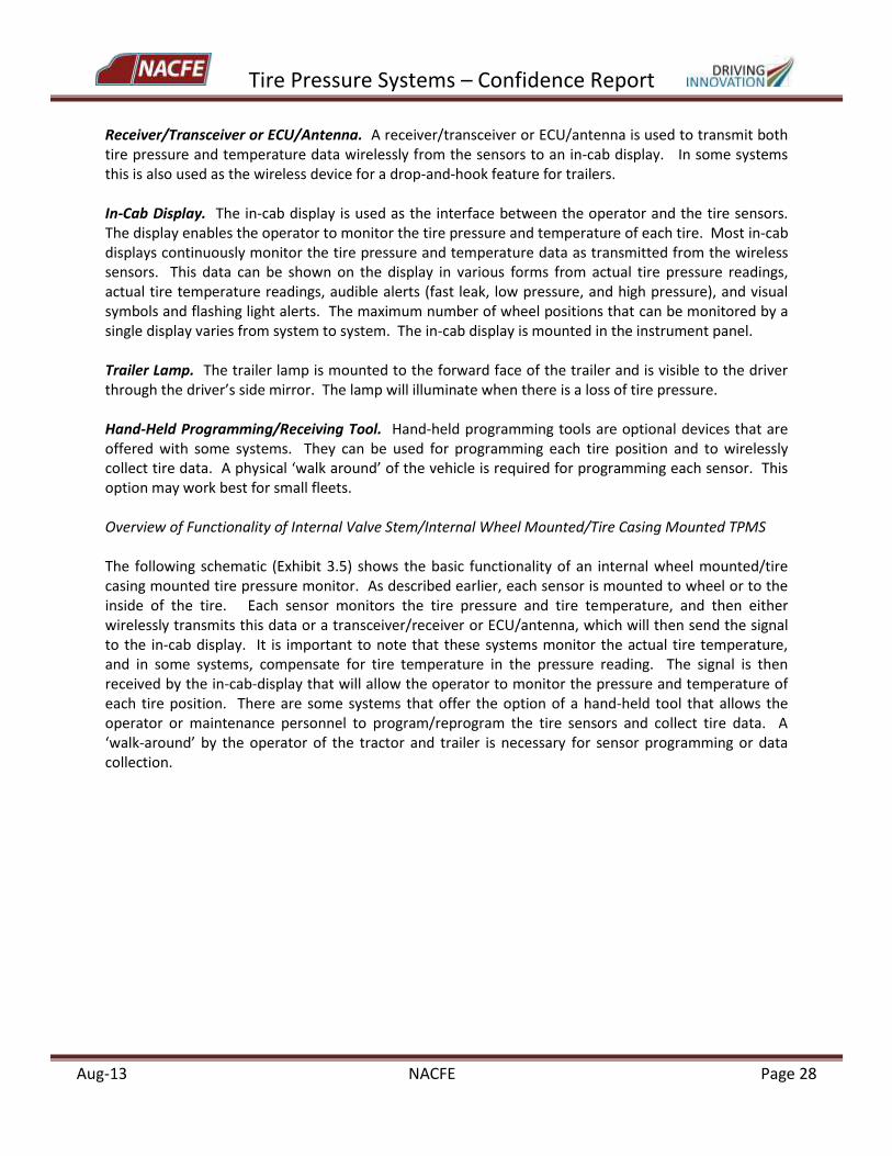
Receiver/Transceiver or ECU/Antenna. A receiver/transceiver or ECU/antenna is used to transmit both tire pressure and temperature data wirelessly from the sensors to an in-cab display. In some systems this is also used as the wireless device for a drop-and-hook feature for trailers. In-Cab Display. The in-cab display is used as the interface between the operator and the tire sensors. The display enables the operator to monitor the tire pressure and temperature of each tire. Most in-cab displays continuously monitor the tire pressure and temperature data as transmitted from the wireless sensors. This data can be shown on the display in various forms from actual tire pressure readings, actual tire temperature readings, audible alerts (fast leak, low pressure, and high pressure), and visual symbols and flashing light alerts. The maximum number of wheel positions that can be monitored by a single display varies from system to system. The in-cab display is mounted in the instrument panel. Trailer Lamp. The trailer lamp is mounted to the forward face of the trailer and is visible to the driver through the driver’s side mirror. The lamp will illuminate when there is a loss of tire pressure. Hand-Held Programming/Receiving Tool. Hand-held programming tools are optional devices that are offered with some systems. They can be used for programming each tire position and to wirelessly collect tire data. A physical ‘walk around’ of the vehicle is required for programming each sensor. This option may work best for small fleets. Overview of Functionality of Internal Valve Stem/Internal Wheel Mounted/Tire Casing Mounted TPMS The following schematic (Exhibit 3.5) shows the basic functionality of an internal wheel mounted/tire casing mounted tire pressure monitor. As described earlier, each sensor is mounted to wheel or to the inside of the tire. Each sensor monitors the tire pressure and tire temperature, and then either wirelessly transmits this data or a transceiver/receiver or ECU/antenna, which will then send the signal to the in-cab display. It is important to note that these systems monitor the actual tire temperature, and in some systems, compensate for tire temperature in the pressure reading. The signal is then received by the in-cab-display that will allow the operator to monitor the pressure and temperature of each tire position. There are some systems that offer the option of a hand-held tool that allows the operator or maintenance personnel to program/reprogram the tire sensors and collect tire data. A ‘walk-around’ by the operator of the tractor and trailer is necessary for sensor programming or data collection.
Tire Pressure Systems – Confidence Report
Aug-13 NACFE Page 29
Exhibit 3.5 Internal Valve Stem/Internal Wheel Mounted/Internal Tire Mounted TPMS
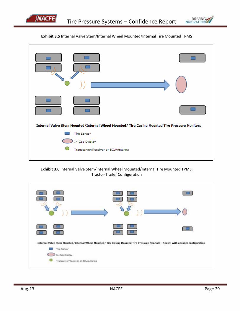
Exhibit 3.6 Internal Valve Stem/Internal Wheel Mounted/Internal Tire Mounted TPMS: Tractor-Trailer Configuration
Tire Pressure Systems – Confidence Report
Aug-13 NACFE Page 30
Tire pressure monitoring systems of this type should exhibit the same capabilities as the external type with the addition of the item below.
The tire pressure system should be able to compensate for the effect of temperature, and to distinguish between an observed change in tire inflation pressure due to tire heating or cooling or due to an observed pressure change caused by actual loss of inflation gas.
The internal tire casing mounted tire pressure monitors should also exhibit the following key features in addition to those mentioned earlier: (FMCSA, 2003)
Integration of a sensor/transmitter in a single electronic device.
Lightweight and small packaging.
Ability to withstand high temperature, shock, and vibration of normal tire operation and deflection cycles.
Ability to sense pressure and tire temperature, and to monitor these parameters continuously.
Ability to “permanently” record various tire-related data such as unique tire ID numbers, and history of incidences of low and high pressure or temperature.
Potential Risks Related to Internal Valve Stem/Internal Wheel Mounted/Tire Casing Mounted TPMS
As indicated in the earlier discussion of external valve stem/external wheel mounted TPMS, different types of systems may present different risks due to their specific components or configuration. In comparison with the previous risk chart for external sensor TPMS, the NACFE team has separated out potential risks associated with the use of internal sensor TPMS as an aid for fleets evaluating the implementation of the technology into their operations. Again, because a risk may or may not occur, fleets should perform a risk analysis and develop a risk response plan before investing in a tire pressure system. Risks are divided into the following categories: Operations, Equipment, Damage, Electrical, and Leakage.
Tire Pressure Systems – Confidence Report
Aug-13 NACFE Page 31
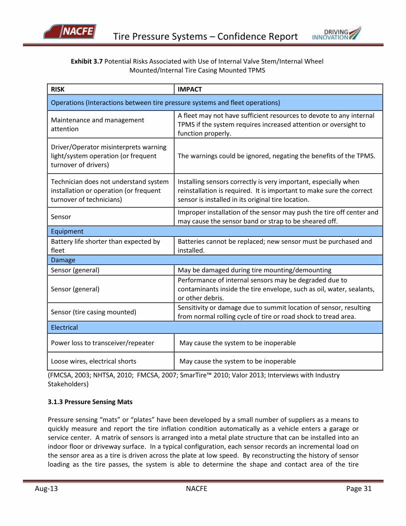
Exhibit 3.7 Potential Risks Associated with Use of Internal Valve Stem/Internal Wheel Mounted/Internal Tire Casing Mounted TPMS
RISK IMPACT
Operations (Interactions between tire pressure systems and fleet operations)
Maintenance and management attention
A fleet may not have sufficient resources to devote to any internal TPMS if the system requires increased attention or oversight to function properly.
Driver/Operator misinterprets warning light/system operation (or frequent turnover of drivers)
The warnings could be ignored, negating the benefits of the TPMS.
Technician does not understand system installation or operation (or frequent turnover of technicians)
Installing sensors correctly is very important, especially when reinstallation is required. It is important to make sure the correct sensor is installed in its original tire location.
Sensor Improper installation of the sensor may push the tire off center and may cause the sensor band or strap to be sheared off.
Equipment
Battery life shorter than expected by fleet
Batteries cannot be replaced; new sensor must be purchased and installed.
Damage
Sensor (general) May be damaged during tire mounting/demounting
Sensor (general) Performance of internal sensors may be degraded due to contaminants inside the tire envelope, such as oil, water, sealants, or other debris.
Sensor (tire casing mounted) Sensitivity or damage due to summit location of sensor, resulting from normal rolling cycle of tire or road shock to tread area.
Electrical
Power loss to transceiver/repeater May cause the system to be inoperable
Loose wires, electrical shorts May cause the system to be inoperable
(FMCSA, 2003; NHTSA, 2010; FMCSA, 2007; SmarTire™ 2010; Valor 2013; Interviews with Industry Stakeholders) 3.1.3 Pressure Sensing Mats Pressure sensing “mats” or “plates” have been developed by a small number of suppliers as a means to quickly measure and report the tire inflation condition automatically as a vehicle enters a garage or service center. A matrix of sensors is arranged into a metal plate structure that can be installed into an indoor floor or driveway surface. In a typical configuration, each sensor records an incremental load on the sensor area as a tire is driven across the plate at low speed. By reconstructing the history of sensor loading as the tire passes, the system is able to determine the shape and contact area of the tire
Tire Pressure Systems – Confidence Report
Aug-13 NACFE Page 32
footprint and the total load being carried by the tire. This information is used to calculate the tire inflation pressure. The sensor mat is connected to a portable floor display unit that reports pressure for each individual tire on the vehicle, including tires mounted in dual configuration. Not all system descriptions state whether they are compatible with wide base single tires. The display unit includes warning lights that will turn green if all tires are properly inflated or red if a tire needs service. The unit may also indicate if there is an unacceptable difference between two tires of a dual assembly, even if each individual tire would not trigger a low-pressure warning. Some systems are configured to record the vehicle license plate or ID number as it passes over the sensor plate, and transmit the vehicle and tire information to a fleet management database. This type of system does not require any equipment installation or modification on the vehicle itself. All system components are placed in a single centralized location per depot or service center. Pressure measurements can be obtained rapidly and automatically for all tires on a vehicle without any manual intervention. Although the effects of load on the tire contact area is automatically taken into account, it is unclear if currently available pressure sensing mats can compensate for pressure variations from tire heating due to rolling or environmental conditions. Users would need to carefully determine the pressure tolerance limits for their specific operations in order to avoid false pressure warnings from the system while also setting sufficiently tight control ranges to ensure that proper tire inflation is maintained. Sensor measurements may be affected by normal contaminants such as dust, oil, dirt, and moisture that are frequently present at fleet sites. Certain pressure mats or plates may be better suited to a controlled test environment rather than a commercial fleet setting. Technology of this type will be most effective in an application where vehicles return to a terminal or central location daily, or at least on a frequent basis. 3.1.4 Manual Tire Pressure Check Procedures in Fleets An air-pressure maintenance program to manually check tire pressures is recommended for all fleets – those who do not use tire systems such as TPMS or ATIS, as well as for those fleets who have adopted a commercial tire pressure system. Effective manual tire pressure programs normally plan for an inflation check of each tire at least once per week. Fleet fueling stations and the maintenance garage are the most common locations for tire pressures to be checked at the fleet terminal. The need for fleets to re-fuel vehicles every day or every few days makes the fuel island a good location to perform tire checks as well as other vehicle inspections, and tire pressure verification can be included in a checklist of duties to be completed while the vehicle is at this station. Drivers or other fleet personnel are usually assigned the responsibility of checking tire inflation. In practice, there is approximately a 50/50 split among fleets in the industry that require drivers to perform tire pressure checks versus those who assign this task to other, most often maintenance, employees. Generally, a manual, or hand-held pressure gauge is used to measure tire inflation pressures.
Tire Pressure Systems – Confidence Report
Aug-13 NACFE Page 33
For fleets whose vehicles may be away from terminals or service centers for extended periods, drivers generally carry the responsibility of maintaining proper tire inflation. This inspection can be accomplished by the driver while at truck stop fuel islands, or a fleet may contract with truck stops or other service providers to perform routine pressure checks while the vehicle is on the road. As a spot check, tire manufacturers may offer tire inspection or audit services to fleets on a quarterly or semi-annual basis. During these inspections, trained tire personnel will check inflation pressures, examine tires for damage conditions, summarize and report results, and recommend actions for fleets to improve their tire management practices. While these audit programs cannot ensure day-to-day conformance to fleet tire pressure targets, they can provide the fleet with independent feedback about the effectiveness of their operations to control and maintain tire pressure. Key elements of a successful manual tire pressure maintenance program include:
Clear designation of who is responsible for checking tire pressure.
Specifying fleet target pressures for all wheel positions.
Documenting the required frequency and procedures for routine tire pressure checks, and communicating that information to fleet personnel.
Providing suitable gauges to drivers or maintenance technicians.
Creating and following a calibration program for tire pressure gauges.
Making sure the program is followed consistently. 3.2 Dual Tire Pressure Equalizer Systems Even if all tires are properly inflated initially, a difference in the pressure between the inner and outer tires of a dual tire assembly can develop during vehicle operations. This condition may occur if the tires are subjected to unequal heating or cooling due to environmental effects, such as direct sunlight, unequal loading between the inner and outer tire, which may occur due to axle bending under load, or slower air seepage in one tire versus the other. Because the two tires are bolted together, they are forced to rotate at the same rate independent of their relative inflation pressures. This will often result in development of faster wear and/or irregular wear of the tire with a lower inflation pressure. Most tire manufacturers recommend that tires in a dual assembly be within 5 psi of each other.
Dual tire pressure equalizer systems are designed to maintain the same inflation pressure between the two tires in a dual assembly. Typically, a central sensor unit is attached to the outer wheel, with tire hoses running from the unit to the valve stems of both tires. The unit allows air to flow back and forth between the two tires, but does not add or remove air during normal operation. For example, if the temperature of the outer tire rises faster than that of the inner tire, resulting in a higher pressure at the outer tire, the equalizer system will slowly transfer air to the inner tire, until both tires are operating at the same pressure. Conversely, if one tire of the dual assembly is leaking, the system will transfer air from the non-leaking tire in an attempt to balance the pressure between the tires.
For either slow, continuous leaks, or for instantaneous air loss in one tire, the system will attempt to maintain the same pressure in both tires until the combined pressure drops by a pre-set threshold level - frequently about a 10 psi reduction across the system - at which point the check valve of the control unit will close, isolating both tires.
Tire Pressure Systems – Confidence Report
Aug-13 NACFE Page 34
Typically, the unit operates in the target range of 60-130 psi, allowing the operator to select a model with the desired target pressure. Different models can be selected per axle position. Most systems include a central fill valve that permits the user to replenish air to both tires without having to remove the hoses.
Dual tire equalizer systems usually include some type of visual display mounted to the hub unit that provides an indication of the air pressure condition for the tires. This is generally a qualitative go/no-go gauge that will show if tires are within the normal pressure range, or are under- or overinflated. However, the operator cannot be certain of the severity of underinflation if the display signals a low pressure condition.
Possible risks associated with the use of dual tire pressure equalizers are categorized into equipment and damage. The valve that operates in these systems may wear over time and it is important to monitor and potentially replace it. The gauge and hoses may become damaged due to road debris and normal wear. If these risks occur, the system may not function correctly and/or inaccurate readings and diminished airflow can result. 3.3 Automatic Tire Inflation Systems (ATIS) For the purpose of this study, an automatic tire inflation system, or ATIS, will be distinguished from TPMS (tire pressure monitoring system) and CTIS (central tire inflation system), by the following features:
The ATIS will operate automatically to restore the tire inflation pressure to its target or specified level, that is, without requiring any manual intervention to initiate re-inflation.
The system will function to maintain target pressure across a normal or typical range of ambient operating conditions.
The system is pre-set to one single target pressure, or to a single target pressure per control unit, this target value being non-adjustable by the vehicle operator from inside the cab during vehicle use.
Actual tire pressure is typically not reported for the tire/wheel assemblies connected to the system.
The distinction between ATIS and CTIS is considered to be the ability of the CTIS to respond to on-demand changes in target pressure which can be achieved with a user interface inside the cab. In contrast, ATIS are generally designed for single target pressure. Further elaboration of the functionality and evaluation of ATIS can be found in SAE Recommended Practice J2848-2. Types of Automatic Tire Inflation Systems (ATIS) Current ATIS are largely separated into two fundamental types, based on air supply, which determines whether the systems are considered to be centralized or distributed.
The most common type of ATIS is a centralized system in which components are connected to the vehicle compressed air supply, most often the trailer air tank that also supports the braking system of the vehicle. Typically, a series of air lines will run from the trailer air tank to the wheel
Tire Pressure Systems – Confidence Report
Aug-13 NACFE Page 35
end, with hoses positioned at the hubcap to route air to the valve stem of each tire. The system is compatible with dual or wide-base single tire configurations. At present, deployment of this category of system is usually limited to trailer applications, taking advantage of the hollow axle to deliver air. It is clear that the drive shaft contained within the housing of the tractor axles prevents this strategy from being used on drive axles.
A second type of ATIS uses self-contained pumps either within individual tires or with one system per wheel end. The system is considered to be “distributed” because there is not a central control for all tires. This type of ATIS relies on rotational motion and deformation of the rolling tire to create pressure gradients that in turn cause the system to deliver atmospheric air (air surrounding the vehicle) directly into the tire. Although the study team was able to identify several patented systems, and instances of these types of systems in development, the availability of commercial or near-commercial products in this category is extremely limited. Nonetheless, because the technical methodology used by these systems represents a fundamentally different approach to tire inflation a characteristic ATIS of this type was selected for inclusion in this report. Since the air supply is not dependent on a vehicle air tank, use of this ATIS technology does not depend on availability of hollow axles, and the systems can support both drive and trailer axles. Either dual or wide-base single tire arrangements can be accommodated.
Four Types of Pressure Losses All ATIS in today’s market work to overcome one or more of the following causes of tire underinflation. To date, the boundaries between each type of pressure loss are not strictly defined. Characteristic air loss rates are indicated to provide an idea of severity of each type of underinflation mechanism. Catastrophic or sudden and complete air loss is not included, as it is not considered to be an appropriate condition to be addressed by ATIS technology.
Natural tire pressure loss due to air diffusion through the tire body. Air losses occur very slowly, and are estimated to be up to 2 psi per month for commercial vehicle tires. The actual leak rate depends on tire construction and the existing inflation pressure.
Air seepage between the tire and the wheel in the bead seat zone, and at improperly tightened or leaking valve stems, cores, or seals (any tire interface, or any internal air chamber interface). In some cases, low temperatures may cause temporary leakage at these interfaces, which could subsequently become airtight as the outdoor temperature or tire temperature increases. Observed leak rates may be in the range of 2 psi per week to 2 psi per day.
Slow to moderate leaks from valve or bead seat irregularities or small punctures, up to an air loss rate of about 5 psi per hour.
Rapid air loss, due to more significant punctures, with loss rates of approximately 1-5 psi per minute or higher, excluding catastrophic air loss occurrences.
Tire Pressure Systems – Confidence Report
Aug-13 NACFE Page 36
3.3.1 ATIS Type 1 – Vehicle Tank Air Source System Components The following section describes the components that are commonly found in this type of system. For the purpose of discussion, the air source will be assumed to be the trailer air tank, as is the case for most currently available ATIS Type 1. Control Unit. The control unit contains the components that will manage airflow from the trailer air tank to the tires. This is primarily accomplished through a pressure regulator inside the control box that is pre-set to the target pressure requested by the fleet user for their specific equipment and operating parameters. Most suppliers of ATIS Type 1 provide a means for the fleet user to adjust the target pressure setting via a knob on the regulator, or other method. However, field adjustment of the target pressure is discouraged. The regulator is designed for one-way flow of air to the tires. All tires connected to a given regulator will be controlled to the same target pressure. If a different target pressure by axle is desired, an additional regulator must be included in the control unit and set to the second target pressure. This situation could occur in the case of a trailer lift axle fitted with a different tire size than on the stationary axle positions. A flow switch, or alternatively a pressure sensor, in the control unit is used to signal when the inflation system is operating to rectify an underinflation condition. The detection system is wired to an indicator lamp on the front of the trailer, which warns the driver that the system is working to inflate one or more tires. This is usually the only electrical component of the inflation system. Air flow higher than a certain threshold, or pressure below a certain threshold, will cause the warning lamp to be turned on. If a vehicle is starting its operation from cold tire conditions – for example after being parked all night – the trailer warning light may be on for 10 minutes while tires are warming up and the system is inflating to target pressure. Continuous illumination of the warning lamp indicates a tire inflation problem, or more rarely a system malfunction, that should be investigated. The control unit may include components that regulate a pressure relief function for cases where tire pressure is higher than a certain level, say 10 psi above the target pressure. If the tire pressure increases to the overpressure set point, air is routed back through the control unit to an exhaust port. Note that this is a venting function for the tires only, and is not the same as the axle vent used to release pressure build-up inside the hollow trailer axle in the case of overheating or emergency operation of wheel-end components. Shut-off Valve or Air Tank Protection Valve. This component isolates the air tank from the tire inflation system in the event of low tank pressure in order to protect the braking capacity of the vehicle. It is located between the air supply tank and the control unit. Hubcap Assembly. The purpose of the hubcap assembly in an ATIS Type 1 is to link the stationary air supply system with the rotating wheel assembly. The rotary union is perhaps the key component of the assembly, being the part of the system most susceptible to wear. Reliability of the rotary union is critical
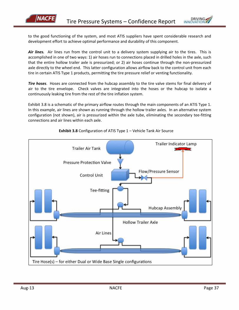
Tire Pressure Systems – Confidence Report
Aug-13 NACFE Page 37
to the good functioning of the system, and most ATIS suppliers have spent considerable research and development effort to achieve optimal performance and durability of this component. Air lines. Air lines run from the control unit to a delivery system supplying air to the tires. This is accomplished in one of two ways: 1) air hoses run to connections placed in drilled holes in the axle, such that the entire hollow trailer axle is pressurized; or 2) air hoses continue through the non-pressurized axle directly to the wheel end. This latter configuration allows airflow back to the control unit from each tire in certain ATIS Type 1 products, permitting the tire pressure relief or venting functionality. Tire hoses. Hoses are connected from the hubcap assembly to the tire valve stems for final delivery of air to the tire envelope. Check valves are integrated into the hoses or the hubcap to isolate a continuously leaking tire from the rest of the tire inflation system. Exhibit 3.8 is a schematic of the primary airflow routes through the main components of an ATIS Type 1. In this example, air lines are shown as running through the hollow trailer axles. In an alternative system configuration (not shown), air is pressurized within the axle tube, eliminating the secondary tee-fitting connections and air lines within each axle.
Exhibit 3.8 Configuration of ATIS Type 1 – Vehicle Tank Air Source
Tire Pressure Systems – Confidence Report
Aug-13 NACFE Page 38
Overview of Functionality of ATIS Type 1 Tire inflation systems of this type should be capable of: (additional general system requirements are described in SAE J2848-2)
Compensating for the natural tire pressure loss due to diffusion through the tire body. Since this phenomenon is occurring on all tires at the same time, the system must be able to supply air to all tires connected to it at this rate.
Compensating for other conditions of relatively low leak rates such as air losses between the tire and the wheel in the bead seat zone, or at improperly tightened or leaking valves stems or cores. As above, the system must be able to supply air to all tires connected to it simultaneously at this rate.
Compensating for moderate leaks from small punctures.
Compensating for certain rapid air loss incidents. (The system cannot compensate for catastrophic air loss.)
Maintaining the tire pressure difference between two tires in a dual assembly to 5 psi or less.
Providing an indication to the driver when the system is functioning to replenish tire air pressure.
Providing an indication of system malfunctions to the driver or maintenance personnel.
Providing an indication to the driver when system is unable to compensate pressure loss of a tire.
Isolating the system from a fast leaking tire or during a tire change out.
Isolating the air tank from the tire inflation system to preserve functionality of braking or other systems supported by vehicle air supply.
Providing clean, moisture-free air supply.
Preventing contamination of system by oil, dust, moisture, chemicals, or other contaminants.
Providing a system of axle venting, in case of malfunction or overheating of other wheel-end components.
Optionally: providing ATIS pressure relief function to prevent over-pressuring of tires. Potential Risks Related to ATIS Type 1 Field or lab testing of the different commercial systems was outside the scope of the NACFE study. Existing publicly available evaluations of ATIS that examine the short-term test-track performance of various products indicate that functioning of currently available systems is largely as designed by manufacturers (FMCSA, 2007). However, different types of systems may present different risks due to their specific components or configuration, or due to the way fleet maintenance and operations functions must interact with the systems. Macro results of a single field operational test of ATIS Type 1 have been presented (FMCSA, 2011), but the complete, finalized report has not been published to date. In the absence of medium- to long-term system durability data, the NACFE team compiled a list of potential risks associated with the use of ATIS Type 1 as an aid for fleets evaluating the implementation of the technology into their operations.
Tire Pressure Systems – Confidence Report
Aug-13 NACFE Page 39
Although there is always the possibility that a given risk may occur, it is also possible that the risks listed below will not occur at all, or occur only with very low frequency. In any case, fleet management should execute a risk analysis and develop at least a basic risk response plan before investing in extensive system installation. Risks are divided into the following categories: Operations, Equipment, Damage, Contamination, Leakage, and Electrical.
Exhibit 3.9 Potential Risks Associated with Use of ATIS Type 1 - Vehicle Tank Air Source
RISK IMPACT
Operations (interactions between tire pressure systems and fleet operations)
Tractor tires cannot be managed by automatic tire inflation system
75% of tire breakdowns are on the trailer; 25% are on the tractor (FMCSA, 2003), even though occurrences of low pressure as measured in the field are approximately the same between tractor and trailer applications. The majority of ATIS products cannot prevent drive/steer tire breakdowns.
ATIS installed on trailers due to be traded within 2-3 years
May not realize payback of system before it is traded.
Trailer air tank pressure is lower than target tire inflation pressure
Tire cannot be inflated to target.
Target inflation pressure for tire is too close to cutoff pressure of Pressure Protection Valve (PPV)
PPV will isolate tire inflation system from trailer air tank at about 70-80 psi for most systems in order to protect braking function of vehicle, cutting off air flow to tires.
PPV installed backwards No pressure detected at regulator. No air flow through regulator.
Control unit pressure regulator mis-set or tampered with
Tire cannot be inflated to target.
Inflate-only system may result in frequent condition of tire pressure above target
Depending on extent and duration of over-pressure condition, impact could be negligible, or could result in an increased sensitivity of the tire to road hazards, degrade tire wear, traction or handling, or could contribute to a harsh ride that displaces or damages cargo.
Inflate/Pressure-relief systems may result in frequent condition of underinflated tires after vehicle is parked and tires cool down
Depending on extent and duration of under-pressure condition, impact could be negligible, or could result in progressive casing damage even when the vehicle is parked. In addition, the tire may stay underinflated for a longer period after the vehicle begins rolling while the system tries to overcome lower pressure induced by ATIS pressure relief operation the previous day.
Pressure level to trigger “relief” function in Inflate/Pressure-relief systems too close to tire target pressure
System simultaneously trying to inflate and exhaust air from tire. For systems with a pressure relief function in addition to an inflation function, the tire inflation level at which air is vented should be 10 psi above the target inflation pressure. This also means that tires could run in an over-pressure condition for a certain duration before the venting function initiates.
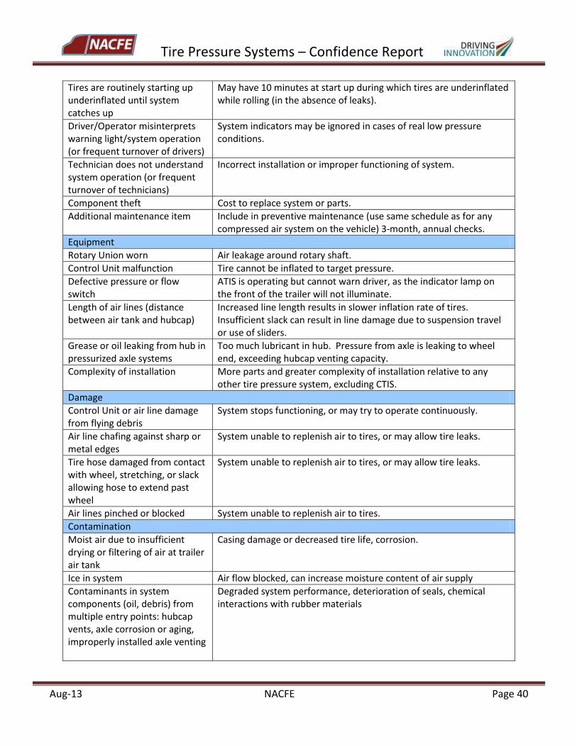
Tire Pressure Systems – Confidence Report
Aug-13 NACFE Page 40
Tires are routinely starting up underinflated until system catches up
May have 10 minutes at start up during which tires are underinflated while rolling (in the absence of leaks).
Driver/Operator misinterprets warning light/system operation (or frequent turnover of drivers)
System indicators may be ignored in cases of real low pressure conditions.
Technician does not understand system operation (or frequent turnover of technicians)
Incorrect installation or improper functioning of system.
Component theft Cost to replace system or parts.
Additional maintenance item Include in preventive maintenance (use same schedule as for any compressed air system on the vehicle) 3-month, annual checks.
Equipment
Rotary Union worn Air leakage around rotary shaft.
Control Unit malfunction Tire cannot be inflated to target pressure.
Defective pressure or flow switch
ATIS is operating but cannot warn driver, as the indicator lamp on the front of the trailer will not illuminate.
Length of air lines (distance between air tank and hubcap)
Increased line length results in slower inflation rate of tires. Insufficient slack can result in line damage due to suspension travel or use of sliders.
Grease or oil leaking from hub in pressurized axle systems
Too much lubricant in hub. Pressure from axle is leaking to wheel end, exceeding hubcap venting capacity.
Complexity of installation More parts and greater complexity of installation relative to any other tire pressure system, excluding CTIS.
Damage
Control Unit or air line damage from flying debris
System stops functioning, or may try to operate continuously.
Air line chafing against sharp or metal edges
System unable to replenish air to tires, or may allow tire leaks.
Tire hose damaged from contact with wheel, stretching, or slack allowing hose to extend past wheel
System unable to replenish air to tires, or may allow tire leaks.
Air lines pinched or blocked System unable to replenish air to tires.
Contamination
Moist air due to insufficient drying or filtering of air at trailer air tank
Casing damage or decreased tire life, corrosion.
Ice in system Air flow blocked, can increase moisture content of air supply
Contaminants in system components (oil, debris) from multiple entry points: hubcap vents, axle corrosion or aging, improperly installed axle venting
Degraded system performance, deterioration of seals, chemical interactions with rubber materials
Tire Pressure Systems – Confidence Report
Aug-13 NACFE Page 41
Electrical
Corrosion of terminals or connectors for trailer indicator lamp
Lamp does not function. Driver not warned that system is operating.
Power loss to controller System unable to replenish air to tires, or system operating at incorrect level.
Loose wires, electrical shorts Lamp does not function. Driver not warned that system is operating
Bad indicator lamp bulb or LED Lamp does not function. Driver not warned that system is operating
Leaks (most important Risk category)
Air leaks at system connectors, fittings
System will try to run continuously. Not able to inflate tire if system leak rate exceeds its capacity to supply air.
Check valves in tire hoses or hubcap malfunction, are blocked or damaged
System will try to run continuously. Not able to isolate tire inflation systems from leaking tire.
Leak in tire hoses or at valve stem due to interaction with tire hose
Tires can deflate when vehicle is parked (system not active, no pressure in trailer air tank).
Onerous procedure to check for system leaks (soapy water solution)
Insufficient technician time to successfully isolate leaking component.
(FMCSA, 2003, PressureGuard®, 2013; P.S.I™, 2006; Hendrickson, 2012; STEMCO, 2012; Interviews with industry stakeholders) 3.3.2 ATIS Type 2 – Direct Atmospheric Air Source with Self-Contained Pump There are two primary strategies for ATIS that use air from the environment surrounding the vehicle (ambient or atmospheric air) to re-inflate the tire, with both approaches using the fundamentally similar concept of a built-in peristaltic pump. In the first case, a built-in roller in a mechanical unit provides the compression that feeds air to the tire. In the second case, the tire itself provides the pumping action. The tire must be rolling for either system type to function. ATIS Type 2 products are “distributed” systems, meaning that the system is self-contained in the tire or at each wheel end, with multiple units on a vehicle. These systems are designed to compensate for the natural loss of tire pressure over time due to the diffusion of air through the tire envelope and other slow to moderate leakages. Type 2 ATIS typically cannot overcome a developing leak at the same level of air loss that can be compensated by Type 1 ATI systems. ATIS Type 2A A small bolt-on disk assembly is mounted to the hub of each wheel end. Air is drawn into a chamber inside the assembly, and is moved through the chamber by an internal roller that compresses the air during rotation of the wheels on the vehicle. It is a self-contained mechanical pump with no batteries, powered by wheel rotation alone. If the air pressure in the tire is less than the pre-set target of the unit, air will move through a tire hose connected from the hub-mounted assembly to the tire valve stem. A single unit is mounted on each wheel end, and can accommodate dual or wide-base single tire configurations. Units are factory-set to a specific target pressure. If different pressures are needed for
Tire Pressure Systems – Confidence Report
Aug-13 NACFE Page 42
drive tires than for trailer tires, separate models should be ordered for each desired target pressure. Conceivably, the units can also be used on the steer axle, although there are currently certain wheel end packaging challenges associated with the mounting of the disk assembly on this wheel position. A potential advantage of this type of system is that it functions fully external to the tire/wheel assembly, with the hub bracket and the tire valve stem as the only interfaces.
ATIS Type 2B
As of the writing of this report, no systems of this type were commercially available for heavy-duty truck tire applications. ATIS Type 2B is often colloquially referred to as a “self-inflating tire”. This terminology is not correct in the strictest sense, but is used because the pumping device that inflates the tire is fully contained within the tire itself. In this system a regulator/sensor is installed inside the tire envelope with an air tube connection to the valve stem. The air tube itself may be located inside the tire air chamber, or may be built into the bead zone as an enclosed ring around the circumference of the tire. Each individual system is preset to a target pressure depending on the tire type and vehicle position. When an underinflation condition is detected, a modified valve stem opens to allow air from outside the tire into the tube. The deformation of the tire during rolling compresses the tube in a pumping motion, delivering external air into the tire/wheel assembly. System function is entirely mechanical and is installed on each individual tire. This tire technology could be implemented on steer, drive, or trailer positions. All ATIS Type 2B products are in prototype or early pre-production phase, and will therefore not be considered in later sections of this report. Details of the operation of ATIS Type 2A and ATIS Type 2B technologies are today relatively strictly guarded under intellectual property and trade secret rights. Some fundamentals related to the systems (but which may not represent final product configurations) are described in the patent literature (Renier, 1993; Benedict, 2012; Richardson, 2012). Overview of Functionality of ATIS Type 2 Tire inflation systems of this type should exhibit the following capabilities, and are generally applicable to either Type 2A or Type 2B systems. The relative novelty of these systems may mean that not all intended functionality has been deployed as of the time of this study.
Compensate for the natural tire pressure losses due to air diffusion through the tire body. Since this phenomenon is occurring on all tires at the same time, the system must be able to supply air to all tires connected to it at this rate.
Compensate for other conditions of relatively low leak rates such as air losses between the tire and the wheel in the bead seat zone, and at improperly tightened or leaking valve stems or cores. As above, the system must be able to supply air to all tires connected to it simultaneously at this rate.
Compensate for moderate leaks from small punctures.
Maintain the tire pressure difference between two tires in a dual assembly to 5 psi or less.
Provide clean, moisture-free air supply.
Prevent contamination of system by oil, dust, moisture, chemicals, or other contaminants.
Not interfere with existing axle venting, in case of malfunction or overheating of other wheel-end components.
Tire Pressure Systems – Confidence Report
Aug-13 NACFE Page 43
Isolate a rapidly leaking tire from the system, if more than one tire is connected to the same unit.
Because of the relatively lower airflow rates of ATIS Type 2, a visible or audible indicator that the system is functioning may be optional.
Focusing on the ATIS Type 2A product category, distinctive features relative to ATIS Type 1 include:
Quick (< 10 minutes per wheel end), simple installation, using a bracket sized for the wheel type and common shop tools.
Minimum number of system components.
Does not depend on trailer air tank pressure condition for proper operation. Less loading on vehicle compressed air systems that also support other vehicle functions. Self-contained system.
Simpler troubleshooting procedure in event of system leaks.
Self-powered mechanical system.
Can be easily applied to drive axles as well as trailer axles.
Lower airflow rates less likely to result in tire over-pressure condition. Potential Risks Related to ATIS Type 2A As indicated in the earlier discussion of ATIS Type 1 risks, there is always the possibility that a given risk may occur. However, it is also possible that the risks listed below will not occur at all, or occur only with very low frequency. In any case, fleet management should execute a risk analysis and develop at least a basic risk response plan before investing in extensive system installation. Risks are divided into the following categories: Operations, Equipment, Damage, Contamination, and Leakage. (Electrical not applicable.)
Exhibit 3.10 Potential Risks Associated with Use of ATIS Type 2A – Direct Atmospheric Air Source
RISK IMPACT
Operations (interactions between tire pressure systems and fleet operations)
Steer tires not managed by automatic tire inflation system
System (hub-attached) components currently are not optimized for mounting on steer axle positions.
Tires routinely start up underinflated until system catches up
May have indeterminate period at vehicle start-up during which tires are underinflated while rolling (in the absence of leaks).
Inflate-only system may result in frequent condition of tire pressure above target. No pressure relief or venting function for tires.
Depending on extent and duration of over-pressure condition, impact could be negligible, or could result in the increased sensitivity of the tire to road hazards, degraded tire wear, traction or handling, or a harsh ride that displaces or damages cargo.
User cannot adjust target inflation pressure after system implementation.
Requires the purchase of additional systems tuned to new target pressure. For certain systems, it may be possible for the supplier to make adjustments on a case-by-case basis.
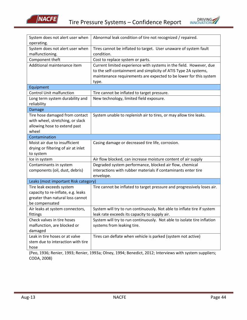
Tire Pressure Systems – Confidence Report
Aug-13 NACFE Page 44
System does not alert user when operating.
Abnormal leak condition of tire not recognized / repaired.
System does not alert user when malfunctioning.
Tires cannot be inflated to target. User unaware of system fault condition.
Component theft Cost to replace system or parts.
Additional maintenance item Current limited experience with systems in the field. However, due to the self-containment and simplicity of ATIS Type 2A systems, maintenance requirements are expected to be lower for this system type.
Equipment
Control Unit malfunction Tire cannot be inflated to target pressure.
Long term system durability and reliability
New technology, limited field exposure.
Damage
Tire hose damaged from contact with wheel, stretching, or slack allowing hose to extend past wheel
System unable to replenish air to tires, or may allow tire leaks.
Contamination
Moist air due to insufficient drying or filtering of air at inlet to system
Casing damage or decreased tire life, corrosion.
Ice in system Air flow blocked, can increase moisture content of air supply
Contaminants in system components (oil, dust, debris)
Degraded system performance, blocked air flow, chemical interactions with rubber materials if contaminants enter tire envelope.
Leaks (most important Risk category)
Tire leak exceeds system capacity to re-inflate, e.g. leaks greater than natural loss cannot be compensated
Tire cannot be inflated to target pressure and progressively loses air.
Air leaks at system connectors, fittings
System will try to run continuously. Not able to inflate tire if system leak rate exceeds its capacity to supply air.
Check valves in tire hoses malfunction, are blocked or damaged
System will try to run continuously. Not able to isolate tire inflation systems from leaking tire.
Leak in tire hoses or at valve stem due to interaction with tire hose
Tires can deflate when vehicle is parked (system not active)
(Peo, 1936; Renier, 1993; Renier, 1993a; Olney, 1994; Benedict, 2012; Interviews with system suppliers; CODA, 2008)
Tire Pressure Systems – Confidence Report
Aug-13 NACFE Page 45
3.4 Central Tire Inflation Systems (CTIS) Like ATIS, Central Tire Inflation Systems (CTIS) use air from the vehicle’s compressed air system to inflate the tires, normally from the vehicle’s air brake tank. The components used in these systems are sensors, manifolds, hoses and valves, harnesses, and the controller/display. In contrast to ATIS, a CTIS set-up includes an ECU in addition to an air regulating system. The vehicle operator has the ability to change the target pressure of the tires from inside the cab, on demand, in response to changes in road or environmental conditions. The ECU controls the signaling to the pneumatic system to inflate or deflate the tires. Air is also delivered to maintain a constant target pressure. CTIS systems are most often found in off-road applications characterized by uneven terrain and costly vehicle equipment, including mining, logging, construction and military operations. Potential risks associated with the use of CTIS are categorized into equipment, leaks, and damage. The slip ring seal that is part of the manifold on the end of the axle could become worn over time due to the rotating hub. The system may cover up a slow leak that is occurring, for example a nail in the tread of the tire. Over time, undetected slow leaks will potentially cause more damage to the tire. Road debris and normal wear may also contribute to damage of the rotary union and the hoses that could inhibit the correct amount of airflow to inflate the tires. 3.5 Passive Pressure Containment Approaches Additional tire pressure product categories offer ways to maintain air in the tire without any action to measure, report, or adjust inflation pressure once a tire has been aired up. Nitrogen inflation attempts to reduce natural pressure losses due to diffusion through the casing. Use of tire sealants, in several forms, is generally aimed at downtime reduction due to air loss caused by small punctures. 3.5.1 Nitrogen Inflation Naturally occurring atmospheric air – the air we breathe – is made up of approximately 78% nitrogen, 21% oxygen, and 1% other gases and includes water vapor. Normally, this is the mixture of the air that is put into tires. A shop system may include a dryer in order to reduce the amount of water vapor in the ambient air supply, decreasing the amount of moisture going into the tire/wheel assembly. Use of concentrated nitrogen instead of atmospheric air slows down the natural pressure loss in tires. Suppliers of nitrogen systems typically use a membrane process to remove oxygen and moisture from the air, taking advantage of faster permeation rates of these components relative to nitrogen. High concentration nitrogen gas is then collected in a pressurized storage tank. Generally, the percent nitrogen in the tank is about 95% or higher. The same permeation properties that slow the diffusion of nitrogen in commercial nitrogen generator systems help keep air in the tire once it has been inflated. Laboratory tests comparing tires inflated with atmospheric air versus tires inflated with high concentration nitrogen have shown that nitrogen inflation can reduce natural pressure losses (Evans, 2009; Park 2011). However, it should be noted that the measured pressure losses are small in both cases. In the absence of other sources of leaks or air seepage, a tire inflated with nitrogen will hold its original pressure longer than one filled with standard air.
Tire Pressure Systems – Confidence Report
Aug-13 NACFE Page 46
Due to the inert nature of nitrogen, tire manufacturers generally concur that the use of high concentration nitrogen as an inflation medium will not have adverse effects on tire inner liners or on tire performance during normal operations. A good tire pressure maintenance program is still needed to detect and prevent air loss from other sources such as leaking valve stems or poor bead seating, which cannot be compensated by nitrogen inflation. Other considerations for the use of nitrogen inflation in long haul commercial vehicle applications include:
Procedures must be established for any time the tires might need additional air when away from maintenance centers and a source of high concentration nitrogen may not be available.
Dry air is a key element for good results with nitrogen inflation (or in fact, for any compressed air system). Moisture in any air source can promote corrosion or degradation of tires and wheels. The use of dry air can also reduce pressure variations due to the response of water vapor to temperature changes (either external temperature or tire operating temperature).
Remember that natural pressure losses can be slowed, but not completely prevented, with nitrogen inflation. Over time, if a normally maintained tire inflated with standard air is not punctured or deflated, the concentration of nitrogen (but not the total amount of air) will gradually increase, and may reach as much as 2%-10% higher concentration of nitrogen than found in atmospheric air. In addition, particularly with highest purity nitrogen (~98% and above), small quantities of oxygen diffuse back into the tire envelope from the surrounding environment, although in smaller concentration than in standard air.
Current automatic tire inflation systems use the trailer air tank or air from surrounding environment as an air source, and will over time return any initial inflation using high concentration nitrogen to standard air nitrogen concentrations.
3.5.2 Tires with Built-in Sealant Layer In recent years, certain tire lines containing a built-in sealant layer have been developed and commercialized for heavy truck applications. The sealant layer is built into the tire between the inner liner and casing ply as part of the normal manufacturing process. During curing, the sealant takes on a gel-like consistency that enables it to flow in the finished tire. For example, if a nail penetrates the tread and the sealant layer, the sealant immediately sticks to the nail and surrounds the area around it, sealing the leak. If the nail is pulled out, sealant is pulled into the puncture area and seals the hole. Positioning the sealant layer between components of the tire construction maintains even distribution of sealant around the tire circumference. In current configurations, sealant is present only in the tread area of the tire, covering the repairable zone of the tire and also the zone in which most punctures occur. Multiple punctures of up to ¼” diameter can be sealed with high reliability, and the product may be effective in repairing damage from larger obstacles. Because sealant has been directly incorporated into the conception of the tire, products with built-in sealant perform with known and controlled properties. They are compatible with normal retread

Tire Pressure Systems – Confidence Report
Aug-13 NACFE Page 47
processes and are designed to undergo multiple retreading. Sealant is not removed or added during retreading. Sealant tires in this category are covered by the same warranty as the equivalent tire model without sealant. For long haul applications, sealant tires are available in wide base single drive and trailer, and in dual trailer fuel-efficient models. The sealant layer can add 8-10 pounds to total tire weight compared to a non-sealant version. Built-in sealant cannot compensate for natural pressure losses, or for leaks or seepage unrelated to tread punctures. Sealant tires can reduce emergency downtime expenses by allowing the tire to maintain pressure at or near its original level until repairs can be made. However, a fleet using sealant tires could potentially run long periods with nails in a tire and not know it, because the tire has not lost air. It is recommended that fleets look for damages to the tread during their routine inspections, and also during weekly tire inflation pressure checks. A potentially interesting assembly of pressure technologies could be to combine tires with built-in sealant – to protect against pressure loss due to road hazards – with an automatic tire inflation system tuned to compensate low volume pressure loss due to natural diffusion of air through the casing. 3.5.3 Aftermarket Sealants Aftermarket sealants are coatings that are applied to the inside of the tire casing as part of the tire mounting process, either by a fleet’s own maintenance shop or by a tire service provider. There is a very broad range of aftermarket sealant products, suppliers, and applications in the market. Sealants of this type have historically been used in agricultural, construction, mining and off-road applications in which tires are routinely subjected to road hazards. More recently, aftermarket sealants have undergone progressive updates to provide products that are better adapted to the use and life-cycles of highway-speed, heavy duty vehicle tires. In general, aftermarket sealants are composed of some type of fibers and/or fillers in a thick liquid suspension. Fibers may be textile filaments or of other composition. Fillers can include small particles of crushed rubber or plastics. Sealant performance depends on its compounding properties, and each supplier creates a specific formulation to adapt the product to a particular usage. Although different suppliers may recommend different practices for sealant application, aftermarket sealants are usually injected before the beads are seated through the valve stem with the valve core removed using a hand pump. In some cases, sealant can be injected into fully mounted and inflated tires using a pneumatic pump system. Manufacturers have generated tables that indicate the amount of sealant, or “dosage”, needed depending on the tire size. For typical highway tires in sizes such as 11 R22.5, 275/80 R22.5 or 295/75 R22.5, the dosage ranges from about 36-50 fluid ounces, or approximately 3-5 pounds per tire for the initial dose. After injection, it is estimated that the sealant spreads to cover the full inner liner of the tire (tread and sidewall area) within about the first hour of rolling. Additional sealant may need to be added during normal use of the tire.
Tire Pressure Systems – Confidence Report
Aug-13 NACFE Page 48
Aftermarket sealants may offer an additional barrier against natural pressure losses due to air migration through the casing, as well as providing an immediate seal around punctures. Certain products may not be capable of sealing punctures, but provide a barrier layer to air permeation only. Products that are designed to seal punctures advertise the ability to reliably treat punctures in the range of ¼” to ½”. Tire warranties will typically remain in effect if the sealant provider has tested and certified use of the sealant in tires. However, if the sealant is judged to be the cause of damage to the inner liner or to have degraded tire performance, the warranty may be voided. Fleets should ask sealant and tire suppliers about potential warranty concerns in advance. Because of the variations in the chemical nature of aftermarket sealants across the wide array of products, and because the sealant has not been an integral part of tire or rim design and development, caution should be taken to ensure that any selected aftermarket sealant:
Is chemically compatible with tires, wheels, and any components that may come in contact with the sealant.
Is approved for speeds associated with highway use and with the speed rating of the tire.
Is compatible with retreading processes. Normally, sealant must be thoroughly cleaned from the tire casing before retreading. In some cases, sealant residue may be flammable at retreading temperatures.
Will perform properly over the range of warm and cold temperatures normally experienced during vehicle operation.
Aftermarket sealant suppliers should clearly state any incompatibilities between their products and active tire pressure systems such as TPMS, ATIS, and dual tire equalizers. Fleet users are encouraged to comprehensively review with these suppliers any risks or concerns they may have if combining electronic or automatic tire pressure systems with specific aftermarket sealants.
4.0 Original Equipment Manufacturers’ Perspectives on Tire Pressure System Integration The NACFE study team interviewed various trailer and tractor builders during the course of the project to gain insights into their experience working with end user fleets and the tire pressure systems suppliers.
4.1 Trailer OEMs
Several trailer OEMs were interviewed who supply different types of trailers including dry van, refrigerated, pup trailers, tankers, flatbeds, dumps and other specialty vocations. Their comments are summarized here.
The procurement of tire pressure systems on newly purchased equipment is growing; approximately 40% of all new trailers built have systems.
For trailers equipped with tire pressure systems, ATIS are more common than TPMS by a ratio of about four to one. Responses ranged from 10–40% for new trailers built in 2013 with ATIS and 5–15% with TPMS.
Tire Pressure Systems – Confidence Report
Aug-13 NACFE Page 49
Increasingly, fleet customers are asking the trailer builders about tire pressure systems. One trailer OEM mentioned that they have now hired an internal sales representative for tire pressure systems, and most stated that they are getting sales, assembly and maintenance training from the system suppliers to better support their customers.
In some cases, trailer manufacturers are assisting the fleets in their retrofit actions.
Axles are being supplied already drilled and tapped to the trailer assembly facilities to better accommodate integration of the tire pressure systems on the production lines.
4.2 Tractor OEMs
The NACFE team met with tractor builders over the course of the project and received the following insights:
Tire pressure is important on tractors as well as on trailers, but tractor builders reiterated the belief that tire pressure is better maintained on tractors than on trailers.
One tire pressure monitoring system is production-available at three of the OEMs, with somewhat limited adoption. It was shared that the system’s payback, even with the higher relative miles driven on the tractor, is not yet sufficient to generate significant demand.
Other manufacturers’ products are available on new equipment via new truck upfitters or dealers prior to delivery of the equipment to the purchaser.
Multiple tractor OEMs shared that they would be willing to engineer various TPMS into their tractors for a reasonable order volume and a few also shared that they are conducting internal studies in order to offer these systems as regular production. This approach could lead to reduced cost for purchasers of tire pressure systems as the components would be integrated in the truck, thus avoiding the upfit costs.
5.0 Summary of Fleet Perspectives and Experiences with Current Tire Pressure Systems Class 8 over the road tractor-trailers are characterized by high miles driven delivering goods such as consumer products in dry van or refrigerated trailers, bulk materials via tankers, freight on flatbeds, etc. There are approximately 1.8 million of these vehicles in the United States and they represent a majority of the fuel used in ground transport and consequently, also consume large quantities of tires. The value of appropriate tire pressure is significant and becomes increasingly so with higher fuel and tire prices. As fleets are actively pursuing efforts to lower their operating costs, manufacturers are responding with technologies that ensure good pressure levels in the tires of Class 8 trucks. Fleets are also realizing that their tire pressure maintenance practices, which at present primarily consist of having drivers manually check tire pressure at all wheel ends, are not sufficient to keep the tires at the appropriate pressure. The fleets shared with NACFE that they recognize the benefits of proper tire pressure and are considering the adoption of technologies that can better ensure it. Conversations typically centered around three primary benefits:
Tire Pressure Systems – Confidence Report
Aug-13 NACFE Page 50
1. Improved safety and fewer roadside breakdowns. Very low tire pressure, which can result from decreasing air in the tire left unattended, can cause a tire rupture and potentially a vehicle accident. At a minimum, it can create a roadside breakdown, causing downtime and cost for a service vehicle to come to the tractor-trailer and replace the tire.
2. Decreased tire life. Operating on low tire pressure causes premature wear of the tire leading to an earlier than expected or needed replacement of the tire.
3. Lower fuel economy. Driving the tire on lower tire pressure increases its rolling resistance and penalizes fuel economy.
For fleets to properly evaluate the effect of low tire pressure on their operating costs and in turn appropriately value the use of a new technology, the fleet should understand the true costs of the items above. These cost elements are prioritized in the order listed above, as fleets, in general, shared the potential benefits of tire pressure systems in this order and generally justified adoption of technologies by identifying improvements in costs in these three categories. Fleets also shared that tire pressure systems can offer enough value to consider retrofitting them on tractors and/or trailers, where there is enough life left on the equipment to justify doing so. Private fleets generally keep their equipment much longer than their for-hire counterparts, who generally sell equipment after four to six years of long-haul use. Also, trailers are much more often candidates for retrofitting, as all fleets tend to keep trailers for most, if not all of their useful life. Retrofitting also has the cost of taking the equipment out of service in order to add the aftermarket components, requiring a longer and costlier labor process - about twice as much cost as if the device was procured on the original equipment. The team concluded that there are some early adopters of tire pressure systems. They include, but are not limited to:
Tankers, and in particular, those hauling hazardous materials where the gravity of a vehicle accident can be severe.
Vehicles with high trailer miles and/or low trailer to tractor ratios, for instance, refrigerated units, where the benefits of proper tire inflation are further amplified with the higher miles.
Duty cycles with diminishing loads, where the diversity of fully-loaded and empty trailers cause tire wear problems and where consistent, sufficient tire pressure can help.
System Selection Reliability Universally fleets shared that the number one criteria for tire pressure system selection is reliability. The equipment simply must not have downtime, as the efficiency of down equipment is zero. Factors such as the variation of available system designs from monitoring to inflation, sensors inside the tire versus outside, vehicle supplied inflation air versus direct atmospheric air supply, provides difficult challenges for fleets in selecting the appropriate system for their use. There is much improved confidence in the current systems in comparison with earlier versions where problems with sensor reliability and durability and component robustness against harsh environments, such as de-icing road chemicals, were more common.
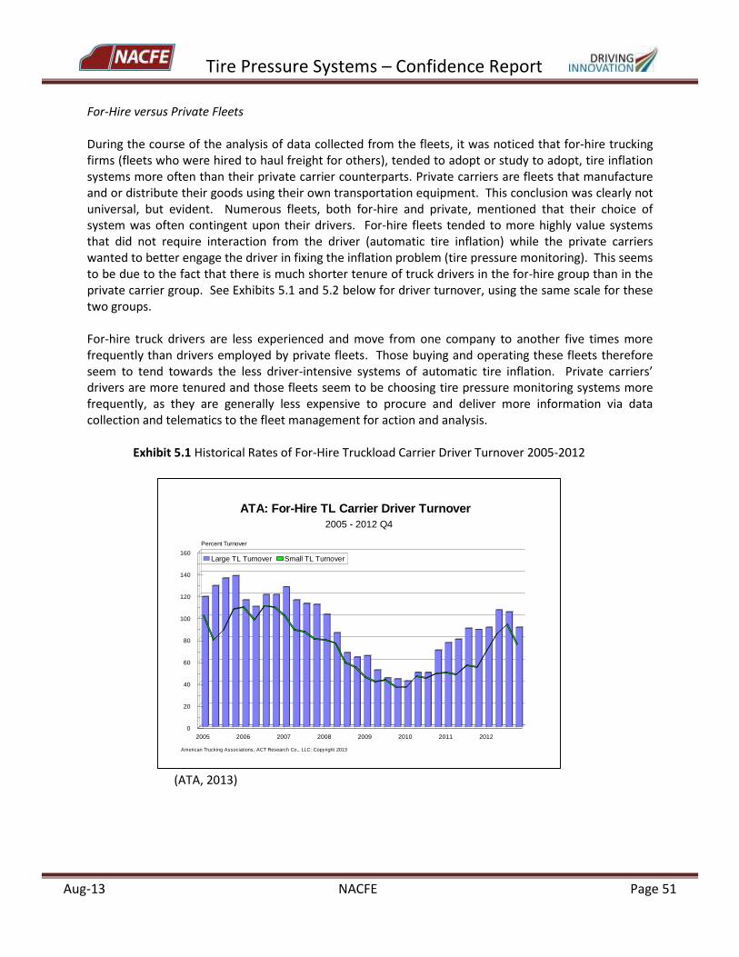
Tire Pressure Systems – Confidence Report
Aug-13 NACFE Page 51
For-Hire versus Private Fleets During the course of the analysis of data collected from the fleets, it was noticed that for-hire trucking firms (fleets who were hired to haul freight for others), tended to adopt or study to adopt, tire inflation systems more often than their private carrier counterparts. Private carriers are fleets that manufacture and or distribute their goods using their own transportation equipment. This conclusion was clearly not universal, but evident. Numerous fleets, both for-hire and private, mentioned that their choice of system was often contingent upon their drivers. For-hire fleets tended to more highly value systems that did not require interaction from the driver (automatic tire inflation) while the private carriers wanted to better engage the driver in fixing the inflation problem (tire pressure monitoring). This seems to be due to the fact that there is much shorter tenure of truck drivers in the for-hire group than in the private carrier group. See Exhibits 5.1 and 5.2 below for driver turnover, using the same scale for these two groups. For-hire truck drivers are less experienced and move from one company to another five times more frequently than drivers employed by private fleets. Those buying and operating these fleets therefore seem to tend towards the less driver-intensive systems of automatic tire inflation. Private carriers’ drivers are more tenured and those fleets seem to be choosing tire pressure monitoring systems more frequently, as they are generally less expensive to procure and deliver more information via data collection and telematics to the fleet management for action and analysis.
Exhibit 5.1 Historical Rates of For-Hire Truckload Carrier Driver Turnover 2005-2012
(ATA, 2013)
2005 2006 2007 2008 2009 2010 2011 2012
0
20
40
60
80
100
120
140
160
Percent Turnover
Large TL Turnover Small TL Turnover
ATA: For-Hire TL Carrier Driver Turnover
2005 - 2012 Q4
American Trucking Associations, ACT Research Co., LLC: Copyright 2013
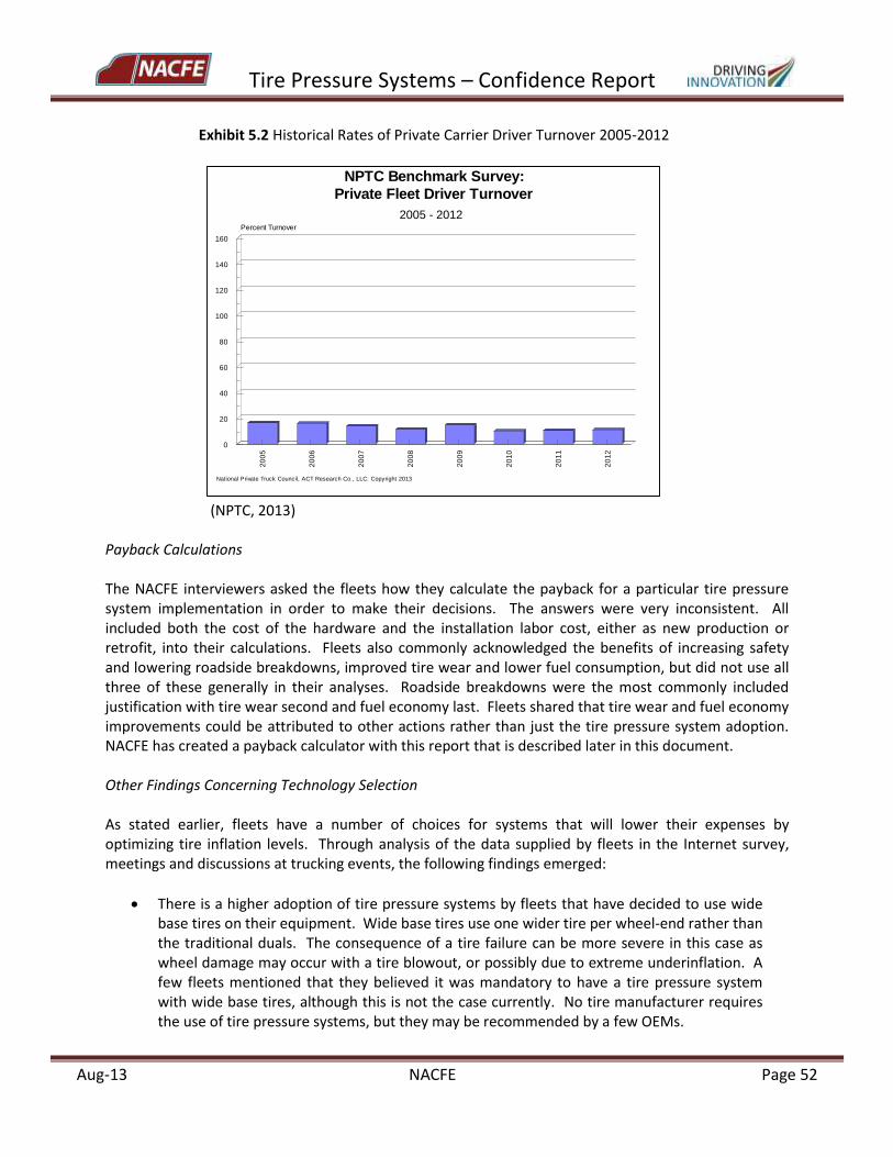
Tire Pressure Systems – Confidence Report
Aug-13 NACFE Page 52
Exhibit 5.2 Historical Rates of Private Carrier Driver Turnover 2005-2012
(NPTC, 2013) Payback Calculations The NACFE interviewers asked the fleets how they calculate the payback for a particular tire pressure system implementation in order to make their decisions. The answers were very inconsistent. All included both the cost of the hardware and the installation labor cost, either as new production or retrofit, into their calculations. Fleets also commonly acknowledged the benefits of increasing safety and lowering roadside breakdowns, improved tire wear and lower fuel consumption, but did not use all three of these generally in their analyses. Roadside breakdowns were the most commonly included justification with tire wear second and fuel economy last. Fleets shared that tire wear and fuel economy improvements could be attributed to other actions rather than just the tire pressure system adoption. NACFE has created a payback calculator with this report that is described later in this document. Other Findings Concerning Technology Selection As stated earlier, fleets have a number of choices for systems that will lower their expenses by optimizing tire inflation levels. Through analysis of the data supplied by fleets in the Internet survey, meetings and discussions at trucking events, the following findings emerged:
There is a higher adoption of tire pressure systems by fleets that have decided to use wide base tires on their equipment. Wide base tires use one wider tire per wheel-end rather than the traditional duals. The consequence of a tire failure can be more severe in this case as wheel damage may occur with a tire blowout, or possibly due to extreme underinflation. A few fleets mentioned that they believed it was mandatory to have a tire pressure system with wide base tires, although this is not the case currently. No tire manufacturer requires the use of tire pressure systems, but they may be recommended by a few OEMs.
20
05
20
06
20
07
20
08
20
09
20
10
20
11
20
12
0
20
40
60
80
100
120
140
160
Percent Turnover
NPTC Benchmark Survey:
Private Fleet Driver Turnover
2005 - 2012
National Private Truck Council, ACT Research Co., LLC: Copyright 2013
Tire Pressure Systems – Confidence Report
Aug-13 NACFE Page 53
Some fleets want to have tire pressure systems on both their tractors and trailers. These include owner-operators who own both the tractor and the trailer and tend to always keep them connected as well as fleets that operate much the same way. In these cases, fleets tend to prefer tire pressure monitoring systems that allow for a common system across both tractor and trailer with the same in-cab communication displays and common telematics data acquisition.
The average trailer-to-tractor ratio for fleets in the Unites States is around 3:1 (NACFE Study fleets reported 3.1:1 in 2013) and can range from a low of around 1.3:1 for refrigerated fleets to over 10:1 for specialty business model situations. Therefore, trailers tend to only be “attached” to a tractor for weeks or even only days at a time, creating a lack of attention to trailer maintenance by many drivers. This situation tends to encourage fleets to consider tire pressure inflation systems that will help ensure appropriate tire pressure if trailers are away from terminals or maintenance centers for an extended period of time, or simply do not get the regular tire pressure checks that tractor tires often receive.
For fleets that are data-driven and who want to understand the tire pressure details for different tire positions, on various equipment types, and when driving diverse routes, TPMS can be the option where the data available for that analysis can be easily communicated, logged and sent to the appropriate resource for analysis.
With respect to tractors, a number of fleets shared that they would really like to have the option of ATIS on them. Central tire inflation systems are currently available for military and off-road use, but are not cost competitive for Class 8 over-the-road trucking. An emerging cost-effective solution is the ATIS Type 2 equipment for tractors.
Fleets see several new features emerging that are very helpful in their expense management. They shared that these include such items as:
o Drop-and-hook feature that allows different tractors and trailers to use a common system when moving from different equipment.
o Warning lights at the wheel end, for instance a green indicator light when pressure is acceptable, yellow if it is somewhat low and red if seriously low, in addition to in-cab reporting.
o Managed pressure relief of tires by ATIS if an increase in ambient temperature drives up the tire pressure.
6.0 Tools – Technology Decision Matrix and Payback Calculator
NACFE has created two tools for the industry based on what we have learned from this study: a technology decision matrix and a payback calculator. Both tools are available as a download from the NACFE website. 6.1 Technology Decision Matrix
This tool identifies the major characteristics of the various Tire Pressure Technology System types in a single chart, shown in Exhibit 6.1. End users, tire pressure systems manufacturers, tractor and trailer builders and others can use filters to highlight specific systems of interest in order to better compare the attributes of the various technologies. This tool is meant to condense the immense amount of
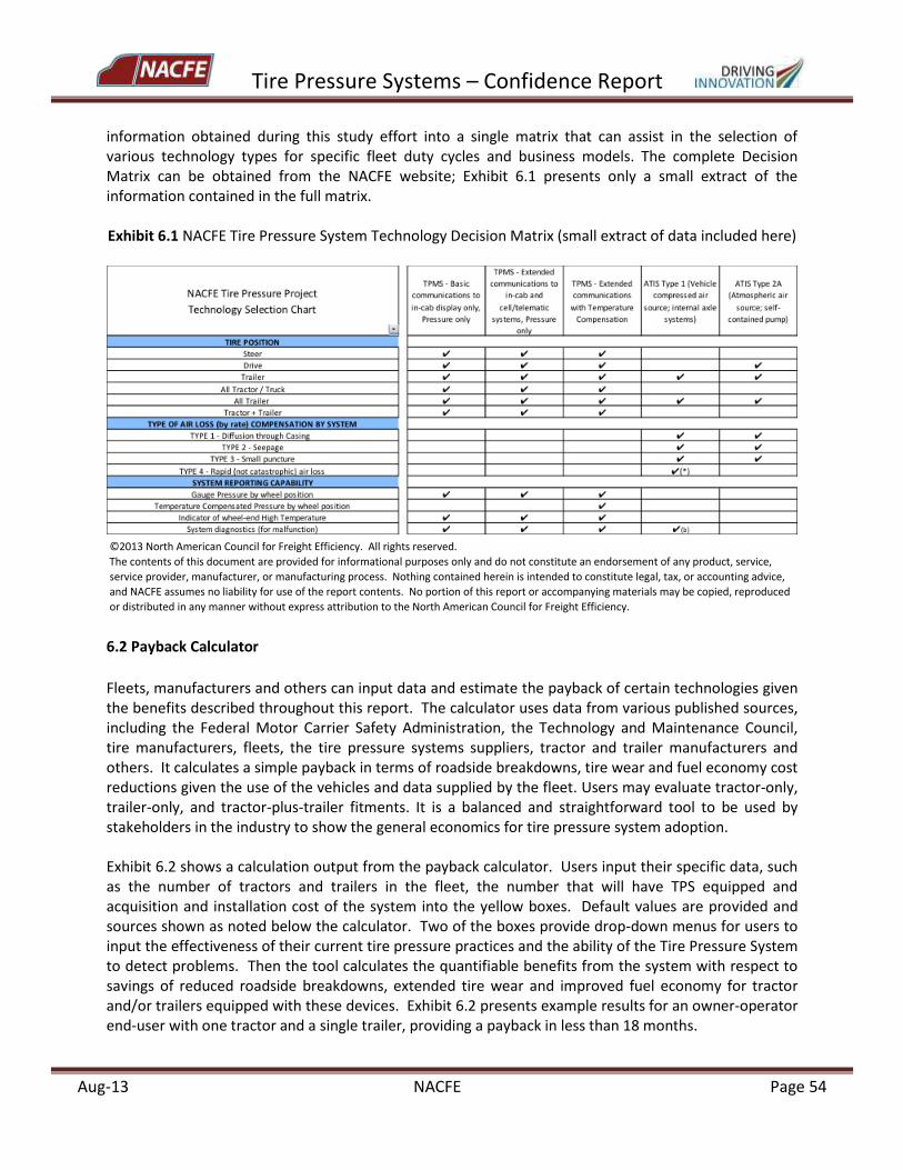
Tire Pressure Systems – Confidence Report
Aug-13 NACFE Page 54
information obtained during this study effort into a single matrix that can assist in the selection of various technology types for specific fleet duty cycles and business models. The complete Decision Matrix can be obtained from the NACFE website; Exhibit 6.1 presents only a small extract of the information contained in the full matrix. Exhibit 6.1 NACFE Tire Pressure System Technology Decision Matrix (small extract of data included here)
6.2 Payback Calculator
Fleets, manufacturers and others can input data and estimate the payback of certain technologies given the benefits described throughout this report. The calculator uses data from various published sources, including the Federal Motor Carrier Safety Administration, the Technology and Maintenance Council, tire manufacturers, fleets, the tire pressure systems suppliers, tractor and trailer manufacturers and others. It calculates a simple payback in terms of roadside breakdowns, tire wear and fuel economy cost reductions given the use of the vehicles and data supplied by the fleet. Users may evaluate tractor-only, trailer-only, and tractor-plus-trailer fitments. It is a balanced and straightforward tool to be used by stakeholders in the industry to show the general economics for tire pressure system adoption. Exhibit 6.2 shows a calculation output from the payback calculator. Users input their specific data, such as the number of tractors and trailers in the fleet, the number that will have TPS equipped and acquisition and installation cost of the system into the yellow boxes. Default values are provided and sources shown as noted below the calculator. Two of the boxes provide drop-down menus for users to input the effectiveness of their current tire pressure practices and the ability of the Tire Pressure System to detect problems. Then the tool calculates the quantifiable benefits from the system with respect to savings of reduced roadside breakdowns, extended tire wear and improved fuel economy for tractor and/or trailers equipped with these devices. Exhibit 6.2 presents example results for an owner-operator end-user with one tractor and a single trailer, providing a payback in less than 18 months.
©2013NorthAmericanCouncilforFreightEfficiency.Allrightsreserved.
Thecontentsofthisdocumentareprovidedforinformationalpurposesonlyanddonotconstituteanendorsementofanyproduct,service,
serviceprovider,manufacturer,ormanufacturingprocess.Nothingcontainedhereinisintendedtoconstitutelegal,tax,oraccountingadvice,
andNACFEassumesnoliabilityforuseofthereportcontents.Noportionofthisreportoraccompanyingmaterialsmaybecopied,reproduced
ordistributedinanymannerwithoutexpressattributiontotheNorthAmericanCouncilforFreightEfficiency.
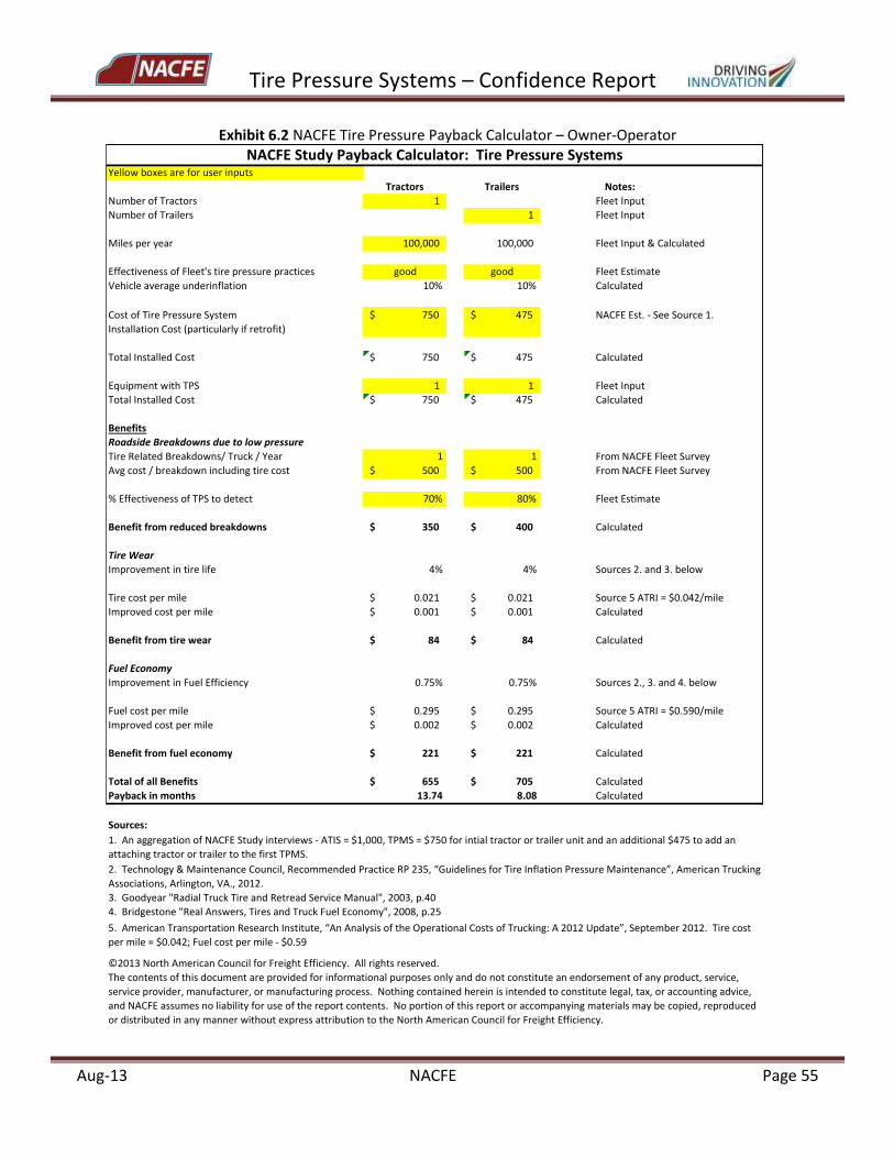
Tire Pressure Systems – Confidence Report
Aug-13 NACFE Page 55
Exhibit 6.2 NACFE Tire Pressure Payback Calculator – Owner-Operator
Yellowboxesareforuserinputs
Tractors Trailers Notes:
NumberofTractors 1 FleetInput
NumberofTrailers 1 FleetInput
Milesperyear 100,000 100,000 FleetInput&Calculated
EffectivenessofFleet'stirepressurepractices good good FleetEstimate
Vehicleaverageunderinflation 10% 10% Calculated
CostofTirePressureSystem 750$ 475$ NACFEEst.-SeeSource1.
InstallationCost(particularlyifretrofit)
TotalInstalledCost 750$ 475$ Calculated
EquipmentwithTPS 1 1 FleetInput
TotalInstalledCost 750$ 475$ Calculated
Benefits
RoadsideBreakdownsduetolowpressure
TireRelatedBreakdowns/Truck/Year 1 1 FromNACFEFleetSurvey
Avgcost/breakdownincludingtirecost 500$ 500$ FromNACFEFleetSurvey
%EffectivenessofTPStodetect 70% 80% FleetEstimate
Benefitfromreducedbreakdowns 350$ 400$ Calculated
TireWear
Improvementintirelife 4% 4% Sources2.and3.below
Tirecostpermile 0.021$ 0.021$ Source5ATRI=$0.042/mile
Improvedcostpermile 0.001$ 0.001$ Calculated
Benefitfromtirewear 84$ 84$ Calculated
FuelEconomy
ImprovementinFuelEfficiency 0.75% 0.75% Sources2.,3.and4.below
Fuelcostpermile 0.295$ 0.295$ Source5ATRI=$0.590/mile
Improvedcostpermile 0.002$ 0.002$ Calculated
Benefitfromfueleconomy 221$ 221$ Calculated
TotalofallBenefits 655$ 705$ Calculated
Paybackinmonths 13.74 8.08 Calculated
Sources:
3.Goodyear"RadialTruckTireandRetreadServiceManual",2003,p.40
4.Bridgestone"RealAnswers,TiresandTruckFuelEconomy",2008,p.25
NACFEStudyPaybackCalculator:TirePressureSystems
©2013NorthAmericanCouncilforFreightEfficiency.Allrightsreserved.
Thecontentsofthisdocumentareprovidedforinformationalpurposesonlyanddonotconstituteanendorsementofanyproduct,service,
serviceprovider,manufacturer,ormanufacturingprocess.Nothingcontainedhereinisintendedtoconstitutelegal,tax,oraccountingadvice,
andNACFEassumesnoliabilityforuseofthereportcontents.Noportionofthisreportoraccompanyingmaterialsmaybecopied,reproduced
ordistributedinanymannerwithoutexpressattributiontotheNorthAmericanCouncilforFreightEfficiency.
5.AmericanTransportationResearchInstitute,“AnAnalysisoftheOperationalCostsofTrucking:A2012Update”,September2012.Tirecost
permile=$0.042;Fuelcostpermile-$0.59
1.AnaggregationofNACFEStudyinterviews-ATIS=$1,000,TPMS=$750forintialtractorortrailerunitandanadditional$475toaddan
attachingtractorortrailertothefirstTPMS.
2.Technology&MaintenanceCouncil,RecommendedPracticeRP235,“GuidelinesforTireInflationPressureMaintenance”,AmericanTrucking
Associations,Arlington,VA.,2012.
Tire Pressure Systems – Confidence Report
Aug-13 NACFE Page 56
7.0 Fleet Case Studies
Two case studies of tire pressure system adoption are presented below. The first describes the adoption of automatic tire inflation systems (ATIS) on trailers by a for-hire fleet and the second, tire pressure monitoring (TPMS) for both tractors and trailers by a private carrier. These case studies are representative of a number of fleets that were interviewed by the study team and are a consolidation of their experiences. They are not actual examples of any one fleet’s experiences, but are characteristic of real fleet operations and provide helpful information for those considering the purchase and use of tire pressure systems.
7.1 Case Study 1: For-Hire Fleet Adopts ATIS for Trailers This fleet is a large carrier in the business of moving truckload freight across the country. They are typical of other large, for-hire fleets and have about 5,000 tractors and 15,000 trailers. Their tractors average about 124,000 miles per year and their 3-to-1 trailer-to-tractor ratio results in trailers averaging about 41,000 miles per year. Fleet long-haul operations require their drivers to be on the road for up to three weeks at a time, driving and living in their sleeper tractors, and driver turnover is high. This fleet’s turnover is slightly better than the industry average but ranges from 85% to over 100%. Trailers are often “dropped” at sites away from fleet terminals and maintenance centers, with other trailers being picked up by the fleet’s tractors and drivers. Given the level of driver turnover and the limited amount of time that a driver is pulling any particular trailer, the fleet was concerned about adding any tire pressure technology that requires greater engagement and involvement by the driver. Therefore, when this fleet investigated tire pressure systems, they preferred automatic tire inflation systems as a technology choice. As various solutions were investigated, they developed a payback calculator and determined through analysis and preliminary testing that they could substantially improve their tire wear with ATIS on their trailers. After extended analysis, they decided to order ATIS on 100% of their new trailer purchases beginning in 2012 and to retrofit the system on all trailers that were nine years old or newer. The payback calculation delivered a return on their investment in approximately one year. Due to the large volume purchase of systems, they were able to receive a discounted unit cost that significantly helped the payback computation. The retrofit option where the ATIS is installed by the trailer dealership or fleet maintenance location added about $110 to the total installed cost versus the OEM installation as part of the new trailer delivery. After making the decision to install ATIS, the fleet decided to conduct a fuel efficiency comparison of about 60 trucks pulling trailers without tire inflation systems to 75 trucks matched with trailers with the system. The test period ran for four months from March through June 2012, and demonstrated that combination vehicles using trailers equipped with ATIS showed an average improvement of 1.5% miles per gallon compared to those vehicles without the systems. To date, there has not been any reliability or durability issues with the product, but the fleet warns that it might be too early to tell. Finally, this fleet has decided not to pursue TPMS for their tractors and is expanding their training for manual pressure checking of tires by drivers and maintenance technicians to ensure the right tire pressure on all tractor tires. Use of TPMS or new ATIS technology for their tractors will be evaluated at a later date. The fleet mentioned that they have been following the developments of ATIS Type 2A,
Tire Pressure Systems – Confidence Report
Aug-13 NACFE Page 57
described in Chapter 3 of this report, as a potential cost-effective tractor solution. Payback results using this fleet’s data in the NACFE tire pressure payback calculator are as shown in Exhibit 7.1 below.

Tire Pressure Systems – Confidence Report
Aug-13 NACFE Page 58
Exhibit 7.1 NACFE Tire Pressure Payback Calculator – For-Hire Fleet with Trailer ATIS
Yellowboxesareforuserinputs
Tractors Trailers Notes:
NumberofTractors 5,000 FleetInput
NumberofTrailers 15,000 FleetInput
Milesperyear 124,000 41,333 FleetInput&Calculated
EffectivenessofFleet'stirepressurepractices good deficient FleetEstimate
Vehicleaverageunderinflation 10% 20% Calculated
CostofTirePressureSystem -$ 750$ NACFEEst.-SeeSource1.
InstallationCost(particularlyifretrofit)
TotalInstalledCost -$ 750$ Calculated
EquipmentwithTPS - 10,000 FleetInput
TotalInstalledCost -$ 7,500,000$ Calculated
Benefits
RoadsideBreakdownsduetolowpressure
TireRelatedBreakdowns/Truck/Year 1 1 FromNACFEFleetSurvey
Avgcost/breakdownincludingtirecost 500$ 500$ FromNACFEFleetSurvey
%EffectivenessofTPStodetect 80% 80% FleetEstimate
Benefitfromreducedbreakdowns -$ 4,000,000$ Calculated
TireWear
Improvementintirelife 4% 16% Sources2.and3.below
Tirecostpermile 0.021$ 0.021$ Source5ATRI=$0.042/mile
Improvedcostpermile 0.001$ 0.003$ Calculated
Benefitfromtirewear -$ 1,388,800$ Calculated
FuelEconomy
ImprovementinFuelEfficiency 0.75% 1.50% Sources2.,3.and4.below
Fuelcostpermile 0.295$ 0.295$ Source5ATRI=$0.590/mile
Improvedcostpermile 0.002$ 0.004$ Calculated
Benefitfromfueleconomy -$ 1,829,000$ Calculated
TotalofallBenefits -$ 7,217,800$ Calculated
Paybackinmonths n/a 12.47 Calculated
Sources:
3.Goodyear"RadialTruckTireandRetreadServiceManual",2003,p.40
4.Bridgestone"RealAnswers,TiresandTruckFuelEconomy",2008,p.25
NACFEStudyPaybackCalculator:TirePressureSystems
2.Technology&MaintenanceCouncil,RecommendedPracticeRP235,“GuidelinesforTireInflationPressureMaintenance”,AmericanTrucking
Associations,Arlington,VA.,2012.
1.AnaggregationofNACFEStudyinterviews-ATIS=$1,000,TPMS=$750forintialtractorortrailerunitandanadditional$475toaddan
attachingtractorortrailertothefirstTPMS.
5.AmericanTransportationResearchInstitute,“AnAnalysisoftheOperationalCostsofTrucking:A2012Update”,September2012.Tirecost
permile=$0.042;Fuelcostpermile-$0.59
©2013NorthAmericanCouncilforFreightEfficiency.Allrightsreserved.
Thecontentsofthisdocumentareprovidedforinformationalpurposesonlyanddonotconstituteanendorsementofanyproduct,service,
serviceprovider,manufacturer,ormanufacturingprocess.Nothingcontainedhereinisintendedtoconstitutelegal,tax,oraccountingadvice,
andNACFEassumesnoliabilityforuseofthereportcontents.Noportionofthisreportoraccompanyingmaterialsmaybecopied,reproduced
ordistributedinanymannerwithoutexpressattributiontotheNorthAmericanCouncilforFreightEfficiency.
Tire Pressure Systems – Confidence Report
Aug-13 NACFE Page 59
7.2 Case Study 2: Private Carrier Adopts TPMS for Tractor and Trailer As described in the fleet perspectives section of this report, private carriers have significantly lower driver turnover than for-hire fleets. It is common for private fleets to have drivers with more than 20 years of experience, and as a result, they are more likely to engage their drivers in the operation and management of their fleets. For example, driver education programs and efficiency incentives are more common at private carriers than at their for-hire counterparts. The primary motivation for the adoption of TPMS at this fleet was the reduction of emergency roadside calls and improved safety of operating their equipment. This is a data-driven organization that decided to adopt TPMS for their trailers six years ago due to its lower acquisition cost and anticipated better payback relative to ATIS, plus the opportunity to educate and involve drivers in the efforts to properly maintain tire pressures. This fleet placed high value on the ability to collect tire inflation history and the ability for data to be sent to fleet operations via telematics. TPMS were retrofitted on most existing trailers beginning in 2007 and is currently specified on all new trailer purchases. Recently, in 2011, this fleet has decided to purchase TPMS on all new tractors. The new tractor TPMS are supplied by a different manufacturer than the trailer systems, an action that was necessary as a common system was not available at the time the decisions were made. The fleet faced a difficult decision of whether to purchase tractor systems with the sensors inside or outside the tire. During preliminary testing, there were some instances of ice and snow accumulation on the sensors mounted on the outside of the tire on the valve stem. In contrast, there were concerns of ease of maintenance and the difficultly of replacement for sensors mounted inside the tire/wheel assembly. This fleet is purchasing a mixture of both systems and will continue to evaluate their performance over time. This fleet is pleased with the implementation of these systems on their vehicles. However, they have not conducted fuel efficiency testing and did not make specific tire wear data available to NACFE. Results from the NACFE payback calculator for this fleet case study are provided in Exhibit 7.2.
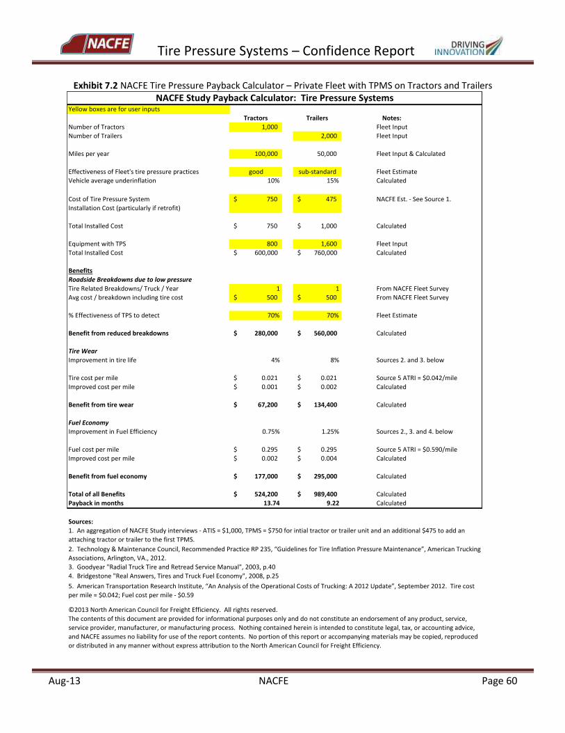
Tire Pressure Systems – Confidence Report
Aug-13 NACFE Page 60
Exhibit 7.2 NACFE Tire Pressure Payback Calculator – Private Fleet with TPMS on Tractors and Trailers
Yellowboxesareforuserinputs
Tractors Trailers Notes:
NumberofTractors 1,000 FleetInput
NumberofTrailers 2,000 FleetInput
Milesperyear 100,000 50,000 FleetInput&Calculated
EffectivenessofFleet'stirepressurepractices good sub-standard FleetEstimate
Vehicleaverageunderinflation 10% 15% Calculated
CostofTirePressureSystem 750$ 475$ NACFEEst.-SeeSource1.
InstallationCost(particularlyifretrofit)
TotalInstalledCost 750$ 1,000$ Calculated
EquipmentwithTPS 800 1,600 FleetInput
TotalInstalledCost 600,000$ 760,000$ Calculated
Benefits
RoadsideBreakdownsduetolowpressure
TireRelatedBreakdowns/Truck/Year 1 1 FromNACFEFleetSurvey
Avgcost/breakdownincludingtirecost 500$ 500$ FromNACFEFleetSurvey
%EffectivenessofTPStodetect 70% 70% FleetEstimate
Benefitfromreducedbreakdowns 280,000$ 560,000$ Calculated
TireWear
Improvementintirelife 4% 8% Sources2.and3.below
Tirecostpermile 0.021$ 0.021$ Source5ATRI=$0.042/mile
Improvedcostpermile 0.001$ 0.002$ Calculated
Benefitfromtirewear 67,200$ 134,400$ Calculated
FuelEconomy
ImprovementinFuelEfficiency 0.75% 1.25% Sources2.,3.and4.below
Fuelcostpermile 0.295$ 0.295$ Source5ATRI=$0.590/mile
Improvedcostpermile 0.002$ 0.004$ Calculated
Benefitfromfueleconomy 177,000$ 295,000$ Calculated
TotalofallBenefits 524,200$ 989,400$ Calculated
Paybackinmonths 13.74 9.22 Calculated
Sources:
3.Goodyear"RadialTruckTireandRetreadServiceManual",2003,p.40
4.Bridgestone"RealAnswers,TiresandTruckFuelEconomy",2008,p.25
NACFEStudyPaybackCalculator:TirePressureSystems
2.Technology&MaintenanceCouncil,RecommendedPracticeRP235,“GuidelinesforTireInflationPressureMaintenance”,AmericanTrucking
Associations,Arlington,VA.,2012.
1.AnaggregationofNACFEStudyinterviews-ATIS=$1,000,TPMS=$750forintialtractorortrailerunitandanadditional$475toaddan
attachingtractorortrailertothefirstTPMS.
5.AmericanTransportationResearchInstitute,“AnAnalysisoftheOperationalCostsofTrucking:A2012Update”,September2012.Tirecost
permile=$0.042;Fuelcostpermile-$0.59
©2013NorthAmericanCouncilforFreightEfficiency.Allrightsreserved.
Thecontentsofthisdocumentareprovidedforinformationalpurposesonlyanddonotconstituteanendorsementofanyproduct,service,
serviceprovider,manufacturer,ormanufacturingprocess.Nothingcontainedhereinisintendedtoconstitutelegal,tax,oraccountingadvice,
andNACFEassumesnoliabilityforuseofthereportcontents.Noportionofthisreportoraccompanyingmaterialsmaybecopied,reproduced
ordistributedinanymannerwithoutexpressattributiontotheNorthAmericanCouncilforFreightEfficiency.
Tire Pressure Systems – Confidence Report
Aug-13 NACFE Page 61
8.0 Perspectives for Future Tire Pressure Systems
During the course of the project, tire pressure systems suppliers and fleet users were asked to share their perspectives on near- to mid-term developments for products that manage and monitor tire inflation in commercial vehicles. This information was combined with results from system testing (NHTSA, 2010), and from recent developments in TPMS from the light-duty vehicle segment which has a longer history of tire pressure sensor use than heavy-duty vehicles. The discussion is divided into four main areas: Functionality, Communications, Operations, and Standardization. Functionality The ability to know the actual tire pressure by wheel position and to capitalize on the transmission capability of electronic sensors and on-board systems are key advantages of TPMS over most current ATIS products. TPMS products are already designed for use on every tire position on the tractor and trailer. Conversely, the fact that the vehicle must be stopped to remedy a low tire pressure condition, which may have occurred over time due to natural air permeation through the casing or even low seepage losses without tire damage, reduces the appeal of TPMS for fleets. Many would prefer to rely on ATIS to control pressure within a given range, even if the actual tire pressures are not reported. Ideally, it would be preferable to combine the reporting capabilities of TPMS with the automatic inflation management functions of ATIS. In terms of future functionality, industry stakeholders frequently cited the following characteristics as most desirable for future systems:
ATIS Type 1 (vehicle compressed air source) available for drive and steer tires, with some type of air routing system through the axle as preferable to air lines attached external to the axle. (Note: most stakeholders did not have experience with the ATIS Type 2 systems.)
Sensor systems combined with ATIS Type 1 or Type 2 to report inflation pressure for each individual tire, and to re-inflate tires when no repair or manual intervention is needed.
ATIS Type 1 or Type 2 with inflate/deflate capability, and which are able to set target pressures linked to load, temperature or other operating conditions.
Ability to block vehicle motion until tires are properly inflated. The total functionality of the first three bullet points above can already be achieved through a disadvantageous practice of purchasing multiple tire pressure systems on each vehicle. This is the most expensive and least integrated option. It is anticipated that as tire pressure systems become more widespread in the commercial freight industry, product or service offers which take the approach of whole vehicle solutions could be more attractive to users than solutions with a comparatively fragmented approach, as is more common today. As always, the balance of functionality, price point, and system reliability will be crucial for technology adoption. Customers should be able to realize a payback for an integrated system within 12-18 months of purchase, without need for further upgrade or replacement of components during the subsequent 2-3 years at a minimum.
Tire Pressure Systems – Confidence Report
Aug-13 NACFE Page 62
Communications Whether through use of tire pressure systems or manual pressure checks, all users want to know the inflation condition of their tires in the most straightforward way possible. The communications chain - from tire measurement to informing driver to maintenance staff to main office to service provider – plays a critical role in the successful management of tire inflation. Different TPMS and ATIS products are distinguished by the type of reporting interface – e.g., in-cab display, buttons to press, blinking lights, audible warnings, and so on – which are provided with the systems. Users must be able to understand the signals and warnings of the system in order to correctly respond to potential underinflation conditions. The design of the user interface(s) has implications for the type of education needed by fleet users and potential service providers. Some of the concerns and/or needs for future systems which were identified include:
Operators don’t understand the difference between flashing and steady warning lights. Other alerts or information provided by the system may be misunderstood. Notifications should be clearer and require less user intervention to get to the root of the problem.
Capitalize on wireless transmission networks on the vehicle or fleet level to enable other functions such as asset tracking, global fleet management, or control of vehicle performances such as speed or stability.
Avoid redundancy of on-board display equipment.
Tire pressure systems need to provide reporting and communications functions that are clear, are adaptable for organizations who want to either increase or limit driver responsibility for tire inflation, and which have the option to integrate with communications solutions that may already be in use in the fleet. On the fleet side, there is a need to prepare the groundwork with training programs for operators, maintenance technicians, and service providers to ensure that tire pressure system signals and alerts are understood, and that the fleet has established and communicated routine procedures for responding to system notifications. Operations In general, tire manufacturers recommend pressure checks on a weekly basis, even if tire pressure systems are in use. Fleets whose vehicles do not return to a terminal or service location on a daily or weekly basis may have to rely on equipment that monitors or manages inflation pressure remotely. On the other hand, fleets whose vehicles return to a terminal on a daily basis may have more options for choosing tire pressure systems or combinations of methods for tracking tire pressure. Discussions with the NACFE team have indicated that, by and large, stakeholders have not reduced their frequency of manual pressure checks, but have instead relied on improved pressure maintenance to reduce costs associated with vehicle downtime, fuel consumption, and tire wear. Historically, one of the biggest concerns with sensor-based systems has been the reliability of data transmission from the sensors. This can be related to sensor durability, which has seen significant improvements in the last decade, or to fleet practices that may compromise sensor performance.
Tire Pressure Systems – Confidence Report
Aug-13 NACFE Page 63
Information collected during a yearlong field test (FMCSA, 2009) reported cases of missing sensor data due to:
Sensors which were damaged during tire mounting or demounting.
Improper installation or re-installation of sensors.
Technicians unaware that TPMS was installed on vehicle.
Tires are replaced, but sensors were not remounted.
Sensors replaced to new wheel position, but system did not recognize the change or was not re-programmed to correctly assign the sensor position.
Lost sensors. If a fleet plans to use a sensor-based system, particularly across a large number of vehicles, a sensor management strategy is needed, which includes:
Procedures to identify vehicles and wheel positions where sensors exist.
Shop work methods for mounting and changing tires on sensor-equipped vehicles.
Sensor replacement procedures and processes for sensor inventory management. This leads into the final section of this chapter, which draws on the experience of sensor-based tire pressure systems in light-duty vehicles. Standardization Since 2007, all new light-duty vehicles in the United States have been equipped with TPMS, usually installed at the vehicle OEM level. In recent years, sensors in these systems have begun to reach the end of their normal battery life, requiring replacement of the sensor package. Although new sensors can usually be obtained at the OEM dealership service center, the correct sensor may not be available if the vehicle owner arranges for tire service to be performed by an independent tire shop. Because TPMS is governed by the TREAD Act in the light-duty segment, in certain instances service providers may be held liable if a vehicle is released from their shop with a TPMS that is not operating properly. The maturing of light-duty TPMS technology has had several impacts on the tire pressure sensor industry. First, there has been a consolidation in the number of companies supplying sensors to both the OEMs and the aftermarket. Second has been the development of “universal” sensors, which are designed to operate with components of any TPMS manufacturer. These trends have made it easier for vehicle servicers to support the wide range of TPMS products on the market, and to accommodate vehicles that may now be equipped with sensors of mixed brands. Deployment of systems with individual tire pressure sensors is much less developed in the heavy-duty freight transport industry. Generally speaking, commercial vehicle TPMS suppliers have designed and patented their sensor technologies; these proprietary sensors can be used with the individual manufacturer’s system only, and not across TPMS brands. At some point in the future, although probably not in the near term, it is expected that commercial vehicle sensors and systems will be subject to the same market pressures seen in light-duty vehicles, and will be driven towards greater component standardization.
Tire Pressure Systems – Confidence Report
Aug-13 NACFE Page 64
Regarding ATIS, there is not a similar experience in light-duty vehicles that presently provides insight into potential market-driven standardization for this technology.
9.0 Study Conclusions
Given the exhaustive efforts conducted by the study team, the following conclusions are provided.
The reliability and durability of the available commercial vehicle tire pressure systems is strong. As with many new innovations, early issues were identified and corrected and the current products are generally believed as acceptable and the companies capable. This project did not complete any testing and this conclusion is reached based on previous reporting by FMCSA and NHTSA on tire pressure system performance and from anecdotal comments from the fleet and tractor and trailer manufacturers.
Adoption of these solutions is increasing. The systems are moving from retrofit via aftermarket to available from the tractor and trailer manufacturers, increasing the quality of the installation and decreasing cost with scale.
Strong options exist for the various truck duty cycles, environmental use and fleet business models that deliver the benefits of ensuring proper tire pressure while eliminating or reducing the barriers to their use.
Creative solutions continue to be developed for improved performance, better reliability and lower overall costs.
The team concludes that the confidence in adopting tire pressure systems should be high given a thorough understanding of each fleet’s needs and investigation and testing of systems to meet those needs. When completed, a fleet should be confident in selecting the best system for their specific needs.

Tire Pressure Systems – Confidence Report
Aug-13 NACFE Page 65
References
American Trucking Associations, ACT Research Co. LLC, 2013. AirBAT RF® Tire Pressure Monitoring System, Brochure #571-3078 and #571-3083, STEMCO, 2013. American Transportation Research Institute, “An Analysis of the Operational Costs of Trucking: A 2012 Update”, September 2012. Benedict, Robert Leon, The Goodyear Tire & Rubber Company, Akron, OH, “Self-Inflating Tire”, U.S. Patent Number 8,113,254, February 14, 2012. Bridgestone Firestone, North American Tire LLC, “Real Answers, Tires& Truck Fuel Economy”, 2008. CODA Development, 2008, www.selfinflatingtire.com. Doran Tire Pressure Monitoring System, 360 HD and 360 SL sales brochures, Doran Manufacturing LLC, 2013. Doran Tire Pressure Monitoring System, 360 HD and 360 SL User Manual #3673, Revision 1, Doran Manufacturing LLC, 2007. Evans, Larry, John Harris, Ed Terrill, and James D. MacIsaac, Jr, “The Effects of Varying the Levels of Nitrogen in the Inflation Gas of Tires on Laboratory Test Performance”, National Highway Traffic Safety Administration, Report No. DOT HS 811 094, March 2009. Federal Motor Carrier Safety Administration, “Commercial Vehicle Tire Condition Sensors”, conducted by Booz-Allen-Hamilton, Inc., McLean, VA., November 2003. Federal Motor Carrier Safety Administration, “Fleet Study of Brake Performance and Tire Pressure Sensors”, U.S. Department of Transportation, Report No. FMCSA-PSV-09-001, conducted by Booz- Allen-Hamilton, Inc., July 2009. Federal Motor Carrier Safety Administration, “Tire Pressure Monitoring And Maintenance Systems Performance Report” U.S. Department of Transportation, Report No. FMCSA-PSV-07-001, conducted by Booz- Allen-Hamilton, Inc. and Fisher Fleet Tire Consulting, January, 2007. Flanigan, Chris, “FMCSA Tire Pressure Monitoring Field Operational Test Results”, presented at Technology & Maintenance Council Annual Meeting, Tampa, FL, February, 2011. Grygier, Paul A., Samuel Daniel, Jr., Richard L. Hoover, and Timothy R. Van Buskirk, “Tire Pressure Monitoring System Tests for Medium and Heavy Trucks and Buses”, National Highway Traffic Safety Administration, Report No. DOT HS 811 314, Washington, D.C., June, 2010. Hendrickson, Technical Procedure, TIREMAAX® CP Integrated and PRO Tire Inflation Systems, Subject: Installation, Service, and Troubleshooting Procedures, Lit No. T51002, May 2012, Revision B.
Tire Pressure Systems – Confidence Report
Aug-13 NACFE Page 66
Installation and Maintenance Manual 14P, Meritor Tire Inflation Systems (MTIS) by P.S.I.™, Standard MTIS, MTIS with ThermALERT™ System, Revision 06-06. “MAP-21, Moving Ahead for Progress in the 21st Century”, Public Law 112-141, U.S. Government Printing Office, Washington, D.C., July 6, 2012. www.gpo.gov/fdsys/pkg/PLAW-112publ141 Michelin North America, Inc., “Michelin® Truck Tire Service Manual”, May 2011. National Private Truck Council, ACT Research Co., 2013 North American Council for Freight Efficiency, “2013 Annual Fleet Fuel Efficiency Benchmark Study”, March 10, 2013.
On-Highway Equipment Control and Communication Network, “SAE Surface Vehicle Recommended Practice J1939/1”, SAE International, November 2012. Park, Jim, “Nitrogen Tire Inflation”, Heavy Duty Trucking, TruckingInfo.com, August 2010. Park, Jim, “Preventing Flat Tires”, Heavy Duty Trucking, TruckingInfo.com, April 2013. Peo, Ralph F., Houde Engineering Corporation, Buffalo, New York, US Patent Number 2,055,983, September 29,1936, “Automatic Tire Inflation Attachment”. PressureGuard® Tire Inflation Systems, Automatic Tire Inflation System Installation Manual, Fleet Air, 2013. PressurePro™ Tire Pressure Monitoring System, on-line parts catalog, Advantage Pressure Pro LLC, 2013. Renier, Grant J., Cycloid Company, Pittsburgh, Pennsylvania, US Patent Number 5,409,049, April 25, 1993, “Tangential Tire Pressurizing and Regulating Apparatus”. Renier, Grant J., Cycloid Company, Pittsburgh, PA., “Tire Pressuring and Regulating Apparatus”, U.S. Patent Number 5,201,968, April 13, 1993. Richardson, Brandon, Palo Alto, CA, “Tire Inflation System”, U.S. Patent Application Publication US 2012/0186714, July 26,2012. Olney, Ross D., Hughes Aircraft Company, Los Angeles, California, US Patent Number 5,355,924, October 18, 1994, “Vehicle Wheel Including Self-Inflating Mechanism”. “Safe, Accountable, Flexible, and Efficient Transportation Equity Act: A Legacy for Users”, Public Law 109-59, U.S. Government Printing Office, Washington, D.C., August, 10, 2005. www.gpo.gov/fdsys/pkg/PLAW-109publ59
Tire Pressure Systems – Confidence Report
Aug-13 NACFE Page 67
SmarTire™ Tire Pressure Monitoring System, Brochure #BW2755, Bendix Commercial Vehicle Systems LLC, 2010. SmarTire™ TPMS Pressure and Temperature Chart, #BW2824, Bendix Commercial Vehicle Systems LLC, 2010. STEMCO Aeris™ Installation and Service Manual, Part Number: 01-571-8300, Revision: 12/4/2012, Rev. B. “TEA-21 Transportation Equity Act for the 21st Century”, Public Law 105-178, U.S. Government Printing Office, Stock No. 869-036-00025-1, Washington, D.C., June 9, 1998. www.fhwa.dot.gov/tea21 Technology & Maintenance Council, Recommended Practice RP 235, “Guidelines for Tire Inflation Pressure Maintenance”, American Trucking Associations, Arlington, VA., 2012. The Goodyear Tire & Rubber Company, “Radial Truck Tire and Retread Service Manual”, 2003. “Tire Pressure Monitoring Systems – For Medium and Heavy Duty Highway Vehicles”, SAE Surface Vehicle Recommended Practice J2848-1, SAE International, April 2010. “Tire Pressure Systems – Maintenance (ATIS) Type for Medium and Heavy Duty Highway Vehicles”, SAE Surface Vehicle Recommended Practice J2848-2, SAE International, June 2011. TIreVigil™ TPMS, Product description brochure, TireStamp, Inc., Rochester Hills, MI., 2013. “TREAD Act, Transportation Recall, Enhancement, Accountability, and Documentation”, Public Law 106-414, U.S. Government Printing Office, Washington, D.C., November 1, 2000. www.gpo.gov/fdsys/pkg/PLAW-106publ414 U.S. Environmental Protection Agency, SmartWay, 2000 Traverwood Drive, Ann Arbor, MI., 2013. www.epa.gov/smartway/partnership Valor Tire Pressure Monitoring System, sales brochure, Valor, 2013.
Tire Pressure Systems – Confidence Report
Aug-13 NACFE Page 68
Appendix A: Product Summary Sheets for Selected Tire Pressure Technology Categories Product summary sheets were developed for seven TPMS and five ATIS products and are included in Appendix A of this report. The appearance, or lack thereof, of an individual commercial product in this Appendix is not an indication of its performance, quality, functionality, or of any endorsement or recommendation by NACFE. NACFE does not endorse products or manufacturers. Individual products in each category can exhibit equivalent performance. An expanded list of tire pressure systems by category, including primary attributes and company contact information, is included in Appendix B. Products are listed in alphabetical order by the product commercial name. Product and product features may not be all-inclusive.
PRODUCT CATEGORY: Tire Pressure Monitoring Systems (TPMS) Sub-Category: Wheel-End Sensors with Transmission Capability
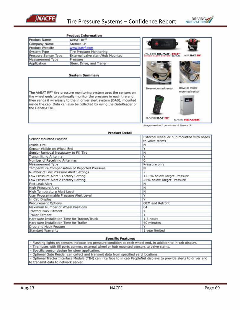
Tire Pressure Systems – Confidence Report
Aug-13 NACFE Page 69
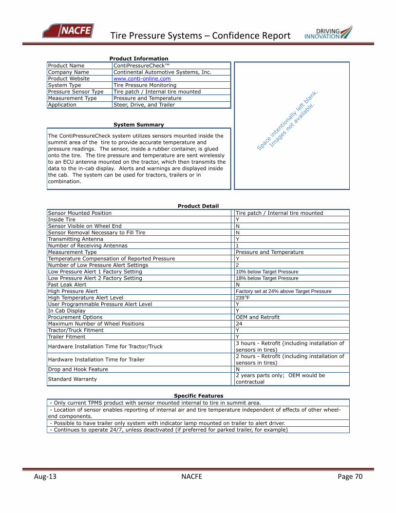
Tire Pressure Systems – Confidence Report
Aug-13 NACFE Page 70
Product Name ContiPressureCheck™
Company Name Continental Automotive Systems, Inc.
Product Website www.conti-online.com
System Type Tire Pressure Monitoring
Pressure Sensor Type Tire patch / Internal tire mounted
Measurement Type Pressure and Temperature
Application Steer, Drive, and Trailer
Sensor Mounted Position Tire patch / Internal tire mounted
Inside Tire Y
Sensor Visible on Wheel End N
Sensor Removal Necessary to Fill Tire N
Transmitting Antenna Y
Number of Receiving Antennas 1
Measurement Type Pressure and Temperature
Temperature Compensation of Reported Pressure Y
Number of Low Pressure Alert Settings 2
Low Pressure Alert 1 Factory Setting 10% below Target Pressure
Low Pressure Alert 2 Factory Setting 18% below Target Pressure
Fast Leak Alert N
High Pressure Alert Factory set at 24% above Target Pressure
High Temperature Alert Level 239oF
User Programmable Pressure Alert Level Y
In Cab Display Y
Procurement Options OEM and Retrofit
Maximum Number of Wheel Positions 24
Tractor/Truck Fitment Y
Trailer Fitment Y
Hardware Installation Time for Tractor/Truck3 hours - Retrofit (including installation of
sensors in tires)
Hardware Installation Time for Trailer2 hours - Retrofit (including installation of
sensors in tires)
Drop and Hook Feature N
Standard Warranty2 years parts only; OEM would be
contractual
- Location of sensor enables reporting of internal air and tire temperature independent of effects of other wheel-
end components.
- Possible to have trailer only system with indicator lamp mounted on trailer to alert driver.
- Continues to operate 24/7, unless deactivated (if preferred for parked trailer, for example)
Product Information
System Summary
The ContiPressureCheck system utilizes sensors mounted inside the
summit area of the tire to provide accurate temperature and
pressure readings. The sensor, inside a rubber container, is glued
onto the tire. The tire pressure and temperature are sent wirelessly
to an ECU antenna mounted on the tractor, which then transmits the
data to the in-cab display. Alerts and warnings are displayed inside
the cab. The system can be used for tractors, trailers or in
combination.
Product Detail
Specific Features
- Only current TPMS product with sensor mounted internal to tire in summit area.
Spac
e intent
iona
lly le
ft blank
.
Imag
es not
ava
ilable.
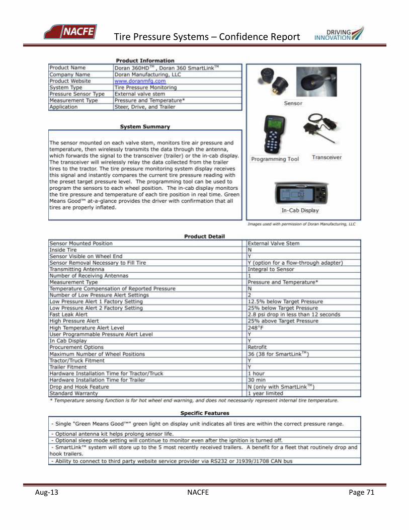
Tire Pressure Systems – Confidence Report
Aug-13 NACFE Page 71
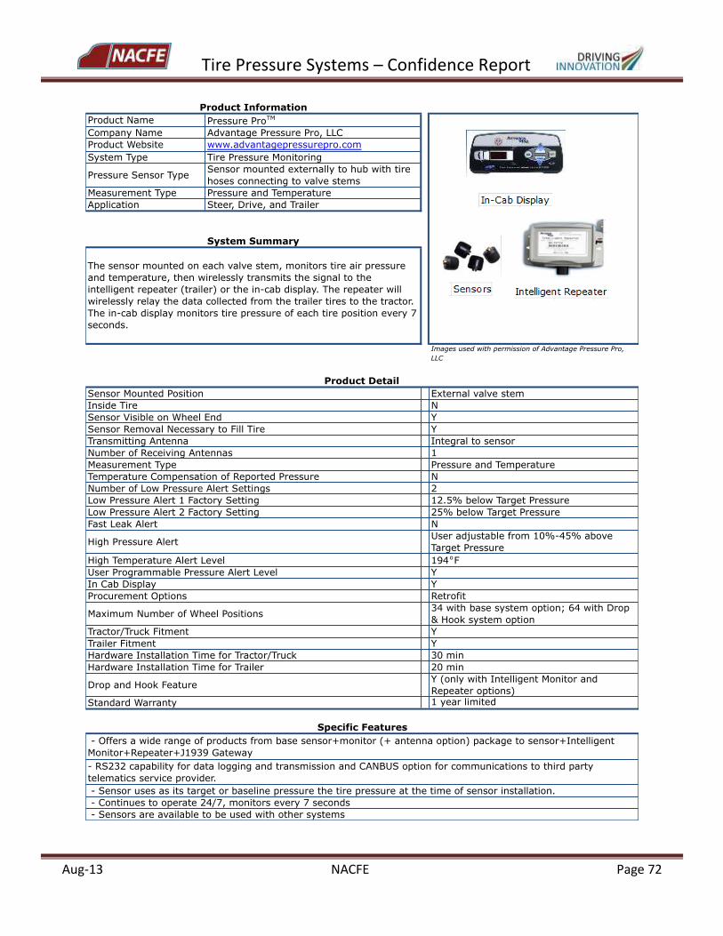
Tire Pressure Systems – Confidence Report
Aug-13 NACFE Page 72
Product Name Pressure ProTM
Company Name Advantage Pressure Pro, LLC
Product Website www.advantagepressurepro.com
System Type Tire Pressure Monitoring
Pressure Sensor TypeSensor mounted externally to hub with tire
hoses connecting to valve stems
Measurement Type Pressure and Temperature
Application Steer, Drive, and Trailer
Images used with permission of Advantage Pressure Pro,
LLC
Sensor Mounted Position External valve stem
Inside Tire N
Sensor Visible on Wheel End Y
Sensor Removal Necessary to Fill Tire Y
Transmitting Antenna Integral to sensor
Number of Receiving Antennas 1
Measurement Type Pressure and Temperature
Temperature Compensation of Reported Pressure N
Number of Low Pressure Alert Settings 2
Low Pressure Alert 1 Factory Setting 12.5% below Target Pressure
Low Pressure Alert 2 Factory Setting 25% below Target Pressure
Fast Leak Alert N
High Pressure AlertUser adjustable from 10%-45% above
Target Pressure
High Temperature Alert Level 194oF
User Programmable Pressure Alert Level Y
In Cab Display Y
Procurement Options Retrofit
Maximum Number of Wheel Positions34 with base system option; 64 with Drop
& Hook system option
Tractor/Truck Fitment Y
Trailer Fitment Y
Hardware Installation Time for Tractor/Truck 30 min
Hardware Installation Time for Trailer 20 min
Drop and Hook FeatureY (only with Intelligent Monitor and
Repeater options)
Standard Warranty 1 year limited
- Sensor uses as its target or baseline pressure the tire pressure at the time of sensor installation.
- Continues to operate 24/7, monitors every 7 seconds
- Sensors are available to be used with other systems
Product Information
System Summary
The sensor mounted on each valve stem, monitors tire air pressure
and temperature, then wirelessly transmits the signal to the
intelligent repeater (trailer) or the in-cab display. The repeater will
wirelessly relay the data collected from the trailer tires to the tractor.
The in-cab display monitors tire pressure of each tire position every 7
seconds.
Product Detail
Specific Features
- Offers a wide range of products from base sensor+monitor (+ antenna option) package to sensor+Intelligent
Monitor+Repeater+J1939 Gateway
- RS232 capability for data logging and transmission and CANBUS option for communications to third party
telematics service provider.
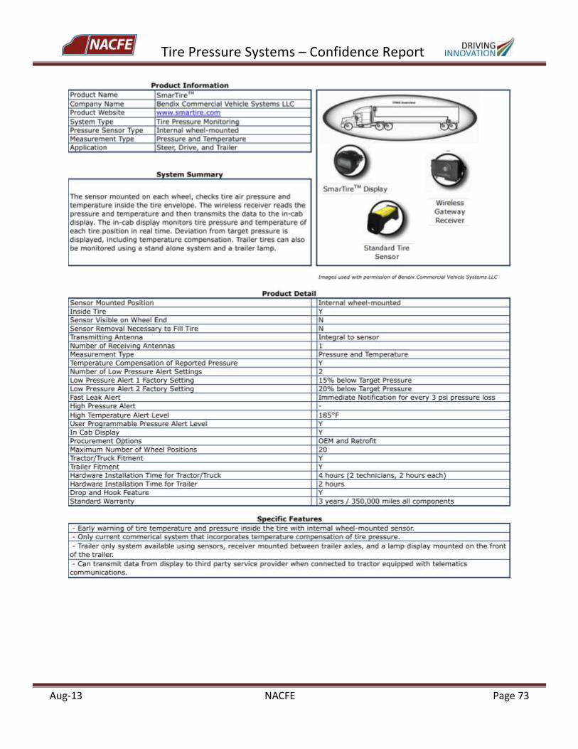
Tire Pressure Systems – Confidence Report
Aug-13 NACFE Page 73
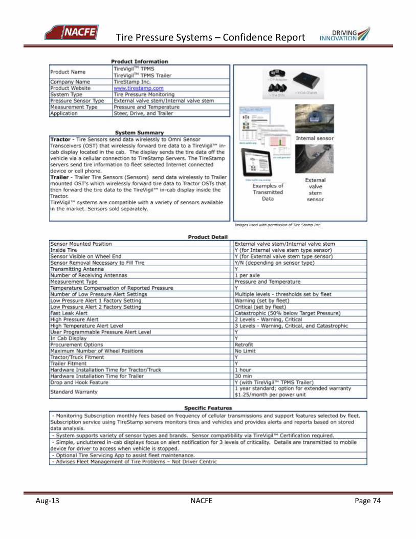
Tire Pressure Systems – Confidence Report
Aug-13 NACFE Page 74
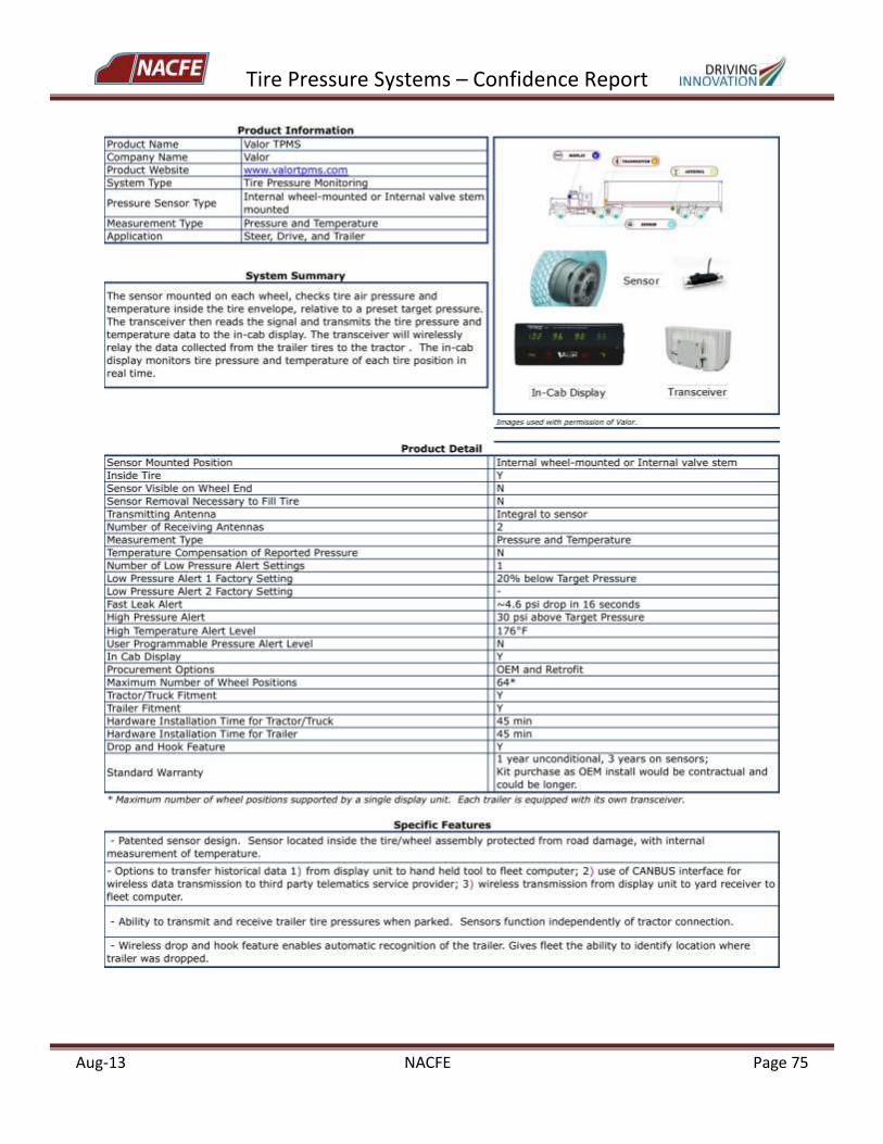
Tire Pressure Systems – Confidence Report
Aug-13 NACFE Page 75
Tire Pressure Systems – Confidence Report
Aug-13 NACFE Page 76
Appendix A: Product Summary Sheets for Selected Tire Pressure Technology Categories
PRODUCT CATEGORY: Automatic Tire Inflation Systems (ATIS) Sub-Category: ATIS Type 1 – Vehicle Tank Air Source
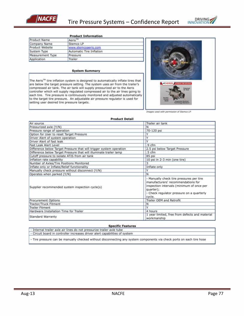
Tire Pressure Systems – Confidence Report
Aug-13 NACFE Page 77
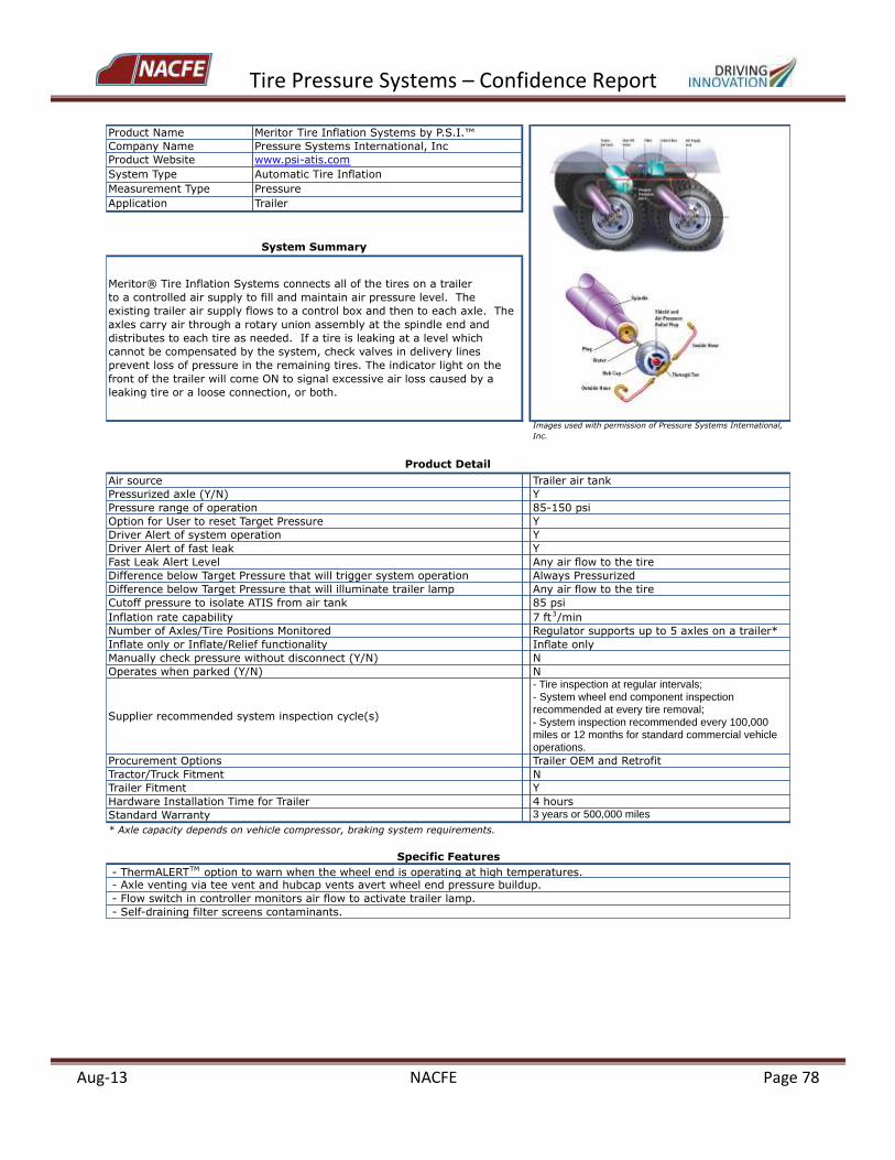
Tire Pressure Systems – Confidence Report
Aug-13 NACFE Page 78
Product Name Meritor Tire Inflation Systems by P.S.I.™
Company Name Pressure Systems International, Inc
Product Website www.psi-atis.com
System Type Automatic Tire Inflation
Measurement Type Pressure
Application Trailer
Images used with permission of Pressure Systems International,
Inc.
Air source Trailer air tank
Pressurized axle (Y/N) Y
Pressure range of operation 85-150 psi
Option for User to reset Target Pressure Y
Driver Alert of system operation Y
Driver Alert of fast leak Y
Fast Leak Alert Level Any air flow to the tire
Difference below Target Pressure that will trigger system operation Always Pressurized
Difference below Target Pressure that will illuminate trailer lamp Any air flow to the tire
Cutoff pressure to isolate ATIS from air tank 85 psi
Inflation rate capability 7 ft3/min
Number of Axles/Tire Positions Monitored Regulator supports up to 5 axles on a trailer*
Inflate only or Inflate/Relief functionality Inflate only
Manually check pressure without disconnect (Y/N) N
Operates when parked (Y/N) N
Supplier recommended system inspection cycle(s)
- Tire inspection at regular intervals;
- System wheel end component inspection
recommended at every tire removal;
- System inspection recommended every 100,000
miles or 12 months for standard commercial vehicle
operations.
Procurement Options Trailer OEM and Retrofit
Tractor/Truck Fitment N
Trailer Fitment Y
Hardware Installation Time for Trailer 4 hours
Standard Warranty 3 years or 500,000 miles
* Axle capacity depends on vehicle compressor, braking system requirements.
- Axle venting via tee vent and hubcap vents avert wheel end pressure buildup.
- Flow switch in controller monitors air flow to activate trailer lamp.
- Self-draining filter screens contaminants.
System Summary
Meritor® Tire Inflation Systems connects all of the tires on a trailer
to a controlled air supply to fill and maintain air pressure level. The
existing trailer air supply flows to a control box and then to each axle. The
axles carry air through a rotary union assembly at the spindle end and
distributes to each tire as needed. If a tire is leaking at a level which
cannot be compensated by the system, check valves in delivery lines
prevent loss of pressure in the remaining tires. The indicator light on the
front of the trailer will come ON to signal excessive air loss caused by a
leaking tire or a loose connection, or both.
Product Detail
Specific Features
- ThermALERTTM option to warn when the wheel end is operating at high temperatures.
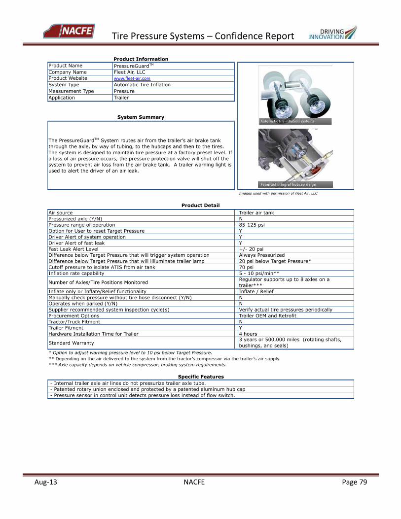
Tire Pressure Systems – Confidence Report
Aug-13 NACFE Page 79
Product Name PressureGuardTM
Company Name Fleet Air, LLC
Product Website www.fleet-air.com
System Type Automatic Tire Inflation
Measurement Type Pressure
Application Trailer
Images used with permission of fleet Air, LLC
Air source Trailer air tank
Pressurized axle (Y/N) N
Pressure range of operation 85-125 psi
Option for User to reset Target Pressure Y
Driver Alert of system operation Y
Driver Alert of fast leak Y
Fast Leak Alert Level +/- 20 psi
Difference below Target Pressure that will trigger system operation Always Pressurized
Difference below Target Pressure that will illluminate trailer lamp 20 psi below Target Pressure*
Cutoff pressure to isolate ATIS from air tank 70 psi
Inflation rate capability 5 - 10 psi/min**
Number of Axles/Tire Positions MonitoredRegulator supports up to 8 axles on a
trailer***
Inflate only or Inflate/Relief functionality Inflate / Relief
Manually check pressure without tire hose disconnect (Y/N) N
Operates when parked (Y/N) N
Supplier recommended system inspection cycle(s) Verify actual tire pressures periodically
Procurement Options Trailer OEM and Retrofit
Tractor/Truck Fitment N
Trailer Fitment Y
Hardware Installation Time for Trailer 4 hours
Standard Warranty3 years or 500,000 miles (rotating shafts,
bushings, and seals)
* Option to adjust warning pressure level to 10 psi below Target Pressure.
** Depending on the air delivered to the system from the tractor’s compressor via the trailer’s air supply.
*** Axle capacity depends on vehicle compressor, braking system requirements.
- Patented rotary union enclosed and protected by a patented aluminum hub cap
- Pressure sensor in control unit detects pressure loss instead of flow switch.
Product Information
System Summary
The PressureGuardTM System routes air from the trailer’s air brake tank
through the axle, by way of tubing, to the hubcaps and then to the tires.
The system is designed to maintain tire pressure at a factory preset level. If
a loss of air pressure occurs, the pressure protection valve will shut off the
system to prevent air loss from the air brake tank. A trailer warning light is
used to alert the driver of an air leak.
Product Detail
Specific Features
- Internal trailer axle air lines do not pressurize trailer axle tube.

Tire Pressure Systems – Confidence Report
Aug-13 NACFE Page 80
Product Name TIREMAAX® PRO
Company Name Hendrickson
Product Website www.hendrickson-intl.com
System Type Automatic Tire Inflation
Measurement Type Pressure
Application Trailer
Images used with permission of Hendrickson
Air source Trailer air tank
Pressurized axle (Y/N) N
Pressure range of operation 80-120 psi dual; 90-120 psi single
Option for User to reset Target Pressure Y
Driver Alert of system operation Y
Driver Alert of fast leak N
Fast Leak Alert Level not applicable
Difference below Target Pressure that will trigger system operation 1 - 2 psi
Difference below Target Pressure that will illuminate trailer lamp
Will illuminate when there is a flow of air to the
tire
Cutoff pressure to isolate ATIS from air tank 70 psi +/- 5 psi
Inflation rate capability 10 psi per 2 min (one tire)
Number of Axles/Tire Positions Monitored Regulator supports up to 3 axles on a trailer*
Inflate only or Inflate/Relief functionality Inflate / Relief
Manually check pressure without disconnect (Y/N) N
Operates when parked (Y/N) N
Supplier recommended system inspection cycle(s)
- Manually check tire pressures per tire
manufacturers' recommendations for inspection
intervals;
- Check indicator lamp and tire hoses on quarterly
cycle;
- System connections and controller operation
annually.
Procurement Options Trailer OEM and Retrofit
Tractor/Truck Fitment N
Trailer Fitment Y
Hardware Installation Time for Trailer 8 hours
Standard Warranty
- 3 years parts and labor for "external" components -
controller, hoses, plumbing;
- 5 years parts and labor - hubcaps, rotary seal, axle
hose;
- 7-years parts and labor when coupled with
Hendrickson HXL7® extended service wheel end
- Retrofit kit: 3 years parts, 1 year labor
* Additional axle capacity depends on vehicle compressor, braking system requirements.
- Flow switch in controller monitors air flow to activate trailer lamp.
- Air relief function back through controller prevents tire overinflation.
- Pressure can be equalized across all tires with pressure relief function.
Product Information
System Summary
TIREMAAX® PRO uses the trailer supply tank to provide a constant air source
to the controller. The TIREMAAX® PRO controller continuously monitors the
air pressure in the tires and adjusts the tire pressure as necessary to
maintain the proper target pressure. The controller is connected to the tires
through internal supply lines inside the trailer axle. These axle lines connect
to a rotary union and tire hoses that allow the air to flow to the rotating
tires. The system provides a pressure relief function to reduce air pressure in
tires reaching an overpressure threshold level.
Product Detail
Specific Features
- Internal trailer axle air lines do not pressurize trailer axle tube.
VentlessHubCap
PatentedAxleFilter
Non-pressurized
Axle
IntegratedHubcapDesign
HendricksonAxleVent
Tire Pressure Systems – Confidence Report
Aug-13 NACFE Page 81
Appendix A: Product Summary Sheets for Selected Tire Pressure Technology Categories
PRODUCT CATEGORY: Automatic Tire Inflation Systems (ATIS) Sub-Category: ATIS Type 2A – Direct Atmospheric Air Source with Self-Contained Pump

Tire Pressure Systems – Confidence Report
Aug-13 NACFE Page 82
Product Name HaloTM Tire Inflator
Company Name Aperia Technologies, Inc.
Product Website www.aperiatech.com
System Type Automatic Tire Inflation
Measurement Type Pressure
Application Steer, Drive, and Trailer
Images used with permission of Aperia Technologies, Inc.
Air source Atmospheric air (air surrounding the vehicle)
Pressurized axle (Y/N) N
Pressure range of operation 30 - 140 psi
Option for User to reset Target Pressure N
Driver Alert of system operation N
Driver Alert of fast leak N
Fast Leak Alert Level not applicable
Difference below Target Pressure that will trigger system operation Always Pressurized
Difference below Target Pressure that will illuminate trailer lamp not applicable
Cutoff pressure to isolate ATIS from air tank not applicable
Inflation rate capability 6 psi/hour per tire
Number of Axles/Tire Positions Monitored 1 Halo unit per wheel end
Inflate only or Inflate/Relief functionality Inflate only
Manually check pressure without disconnect (Y/N) Y
Operates when parked (Y/N) N
Supplier recommended system inspection cycle(s)
Inspect tire hoses, unit mounting, and clean
intake filter at each tire change, at least once
per year.
Procurement Options Retrofit
Tractor/Truck Fitment Y (drive)
Trailer Fitment Y
Hardware Installation Time for Trailer 5-10 minutes per wheel end
Standard Warranty 3-year limited
- Current product can be used on both drive and trailer applications; does not rely on air line connections through or along the
axles to a vehicle air source.
- Bolt-on to a variety of hub types for quick installation.
Product Information
System Summary
When the vehicle is moving, outside air is drawn into a central hub-mounted
device and is compressed, building up pressure. The unit provides air flow
as long as air pressure inside the tire is below the pre-set target inflation
pressure of the device. Air flow shuts off automatically when the desired air
pressure level is reached.
Product Detail
Specific Features
- Self-contained pump unit uses the wheel rotational motion to maintain optimal tire pressure.
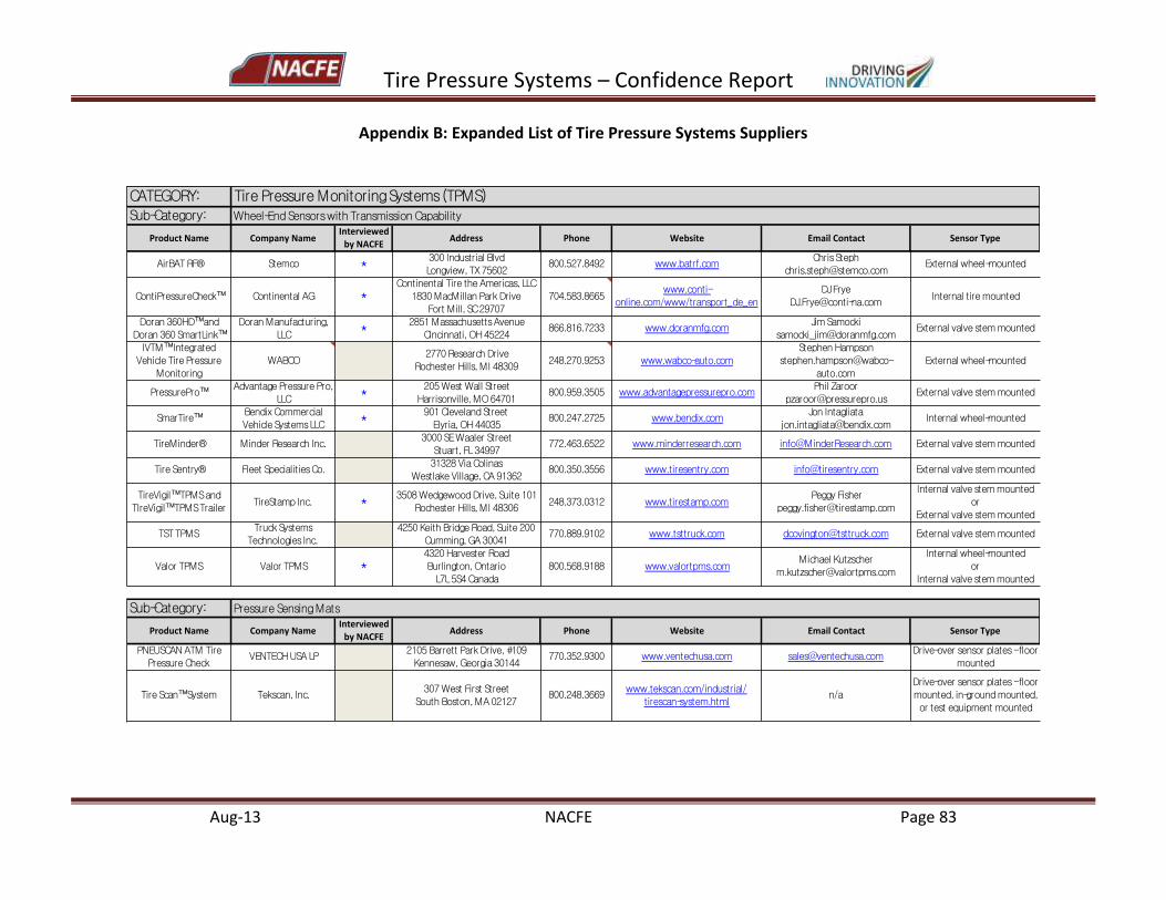
Tire Pressure Systems – Confidence Report
Aug-13 NACFE Page 83
Appendix B: Expanded List of Tire Pressure Systems Suppliers
CATEGORY:Sub-Category:
ProductName CompanyNameInterviewed
byNACFEAddress Phone Website EmailContact SensorType
AirBATRF® Stemco *300IndustrialBlvd
Longview,TX75602800.527.8492 www.batrf.com
ChrisSteph
ContiPressureCheck™ ContinentalAG *ContinentalTiretheAmericas,LLC
1830MacMillanParkDrive
FortMill,SC29707
704.583.8665www.conti-
online.com/www/transport_de_en
DJFrye
Doran360HD™and
Doran360SmartLink™
DoranManufacturing,
LLC*
2851MassachusettsAvenue
Cincinnati,OH45224866.816.7233 www.doranmfg.com
JimSamocki
IVTM™Integrated
VehicleTirePressure
Monitoring
WABCO2770ResearchDrive
RochesterHills,MI48309248.270.9253 www.wabco-auto.com
StephenHampson
stephen.hampson@wabco-
auto.com
Externalwheel-mounted
PressurePro™AdvantagePressurePro,
LLC *205WestWallStreet
Harrisonville,MO64701800.959.3505 www.advantagepressurepro.com
PhilZaroor
SmarTire™BendixCommercial
VehicleSystemsLLC*
901ClevelandStreet
Elyria,OH44035800.247.2725 www.bendix.com
JonIntagliata
TireMinder® MinderResearchInc.3000SEWaalerStreet
Stuart,FL34997772.463.6522 www.minderresearch.com [email protected] Externalvalvestemmounted
TireSentry® FleetSpecialitiesCo.31328ViaColinas
WestlakeVillage,CA91362800.350.3556 www.tiresentry.com [email protected] Externalvalvestemmounted
TireVigil™TPMSandTIreVigil™TPMSTrailer
TireStampInc. *3508WedgewoodDrive,Suite101RochesterHills,MI48306
248.373.0312 www.tirestamp.comPeggyFisher
Internalvalvestemmountedor
Externalvalvestemmounted
TSTTPMSTruckSystems
TechnologiesInc.
4250KeithBridgeRoad,Suite200
Cumming,GA30041770.889.9102 www.tsttruck.com [email protected] Externalvalvestemmounted
ValorTPMS ValorTPMS *4320HarvesterRoad
Burlington,Ontario
L7L5S4Canada
800.568.9188 www.valortpms.comMichaelKutzscher
Internalwheel-mounted
or
Internalvalvestemmounted
Sub-Category:
ProductName CompanyNameInterviewed
byNACFEAddress Phone Website EmailContact SensorType
PNEUSCANATMTire
PressureCheckVENTECHUSALP
2105BarrettParkDrive,#109
Kennesaw,Georgia30144770.352.9300 www.ventechusa.com [email protected]
Drive-oversensorplates-floor
mounted
TireScan™System Tekscan,Inc.307WestFirstStreet
SouthBoston,MA02127800.248.3669
www.tekscan.com/industrial/
tirescan-system.htmln/a
Drive-oversensorplates-floor
mounted,in-groundmounted,
ortestequipmentmounted
TirePressureMonitoringSystems(TPMS)Wheel-EndSensorswithTransmissionCapability
PressureSensingMats
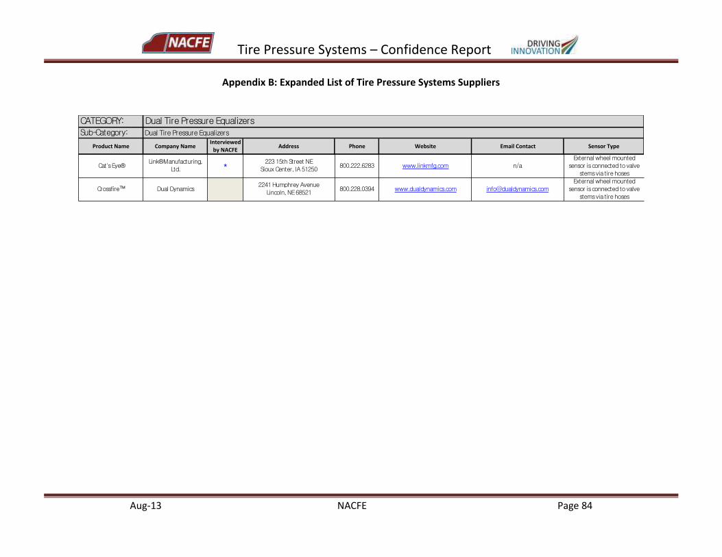
Tire Pressure Systems – Confidence Report
Aug-13 NACFE Page 84
Appendix B: Expanded List of Tire Pressure Systems Suppliers
CATEGORY:Sub-Category:
ProductName CompanyNameInterviewedbyNACFE
Address Phone Website EmailContact SensorType
Cat'sEye®Link®Manufacturing,
Ltd. *22315thStreetNESiouxCenter,IA51250
800.222.6283 www.linkmfg.com n/aExternalwheelmountedsensorisconnectedtovalvestemsviatirehoses
Crossfire™ DualDynamics2241HumphreyAvenueLincoln,NE68521
800.228.0394 www.dualdynamics.com info@dualdynamics.comExternalwheelmountedsensorisconnectedtovalvestemsviatirehoses
DualTirePressureEqualizersDualTirePressureEqualizers
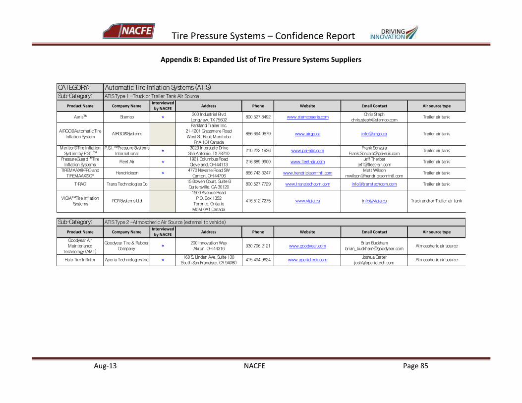
Tire Pressure Systems – Confidence Report
Aug-13 NACFE Page 85
Appendix B: Expanded List of Tire Pressure Systems Suppliers
CATEGORY:Sub-Category:
ProductName CompanyNameInterviewed
byNACFEAddress Phone Website EmailContact Airsourcetype
Aeris™ Stemco *300IndustrialBlvd
Longview,TX75602800.527.8492 www.stemcoaeris.com
ChrisSteph
AIRGO®AutomaticTire
InflationSystemAIRGO®Systems
ParklandTrailerInc.21-1201GrassmereRoad
WestSt.Paul,Manitoba
R4A1C4Canada
866.694.9679 www.airgo.ca [email protected] Trailerairtank
Meritor®TireInflationSystembyP.S.I.™
P.S.I.™PressureSystemsInternational *
3023InterstateDriveSanAntonio,TX78210
210.222.1926 www.psi-atis.comFrankSonzala
PressureGuard™Tire
InflationSystemsFleetAir *
1921ColumbusRoad
Cleveland,OH44113216.689.9900 www.fleet-air.com
JeffTherber
TIREMAAX®PROandTIREMAAX®CP
Hendrickson *4770NavarreRoadSWCanton,OH44706
866.743.3247 www.hendrickson-intl.comMattWilson
T-RAC TransTechnologiesCo15BowenCourt,SuiteB
Cartersville,GA30120800.527.7729 www.transtechcom.com [email protected] Trailerairtank
VIGIA™TireInflation
SystemsRCRSystemsLtd
1500AvenueRoad
P.O.Box1352
Toronto,Ontario
M5M0A1Canada
416.512.7275 www.vigia.ca [email protected] Truckand/orTrailerairtank
Sub-Category:
ProductName CompanyNameInterviewedbyNACFE
Address Phone Website EmailContact Airsourcetype
GoodyearAir
Maintenance
Technology(AMT)
GoodyearTire&Rubber
Company*
200InnovationWay
Akron,OH44316330.796.2121 www.goodyear.com
BrianBuckham
HaloTireInflator AperiaTechnologiesInc. *160S.LindenAve,Suite130
SouthSanFrancisco,CA94080415.494.9624 www.aperiatech.com
JoshuaCarter
AutomaticTireInflationSystems(ATIS)ATISType1-TruckorTrailerTankAirSource
ATISType2-AtmosphericAirSource(externaltovehicle)
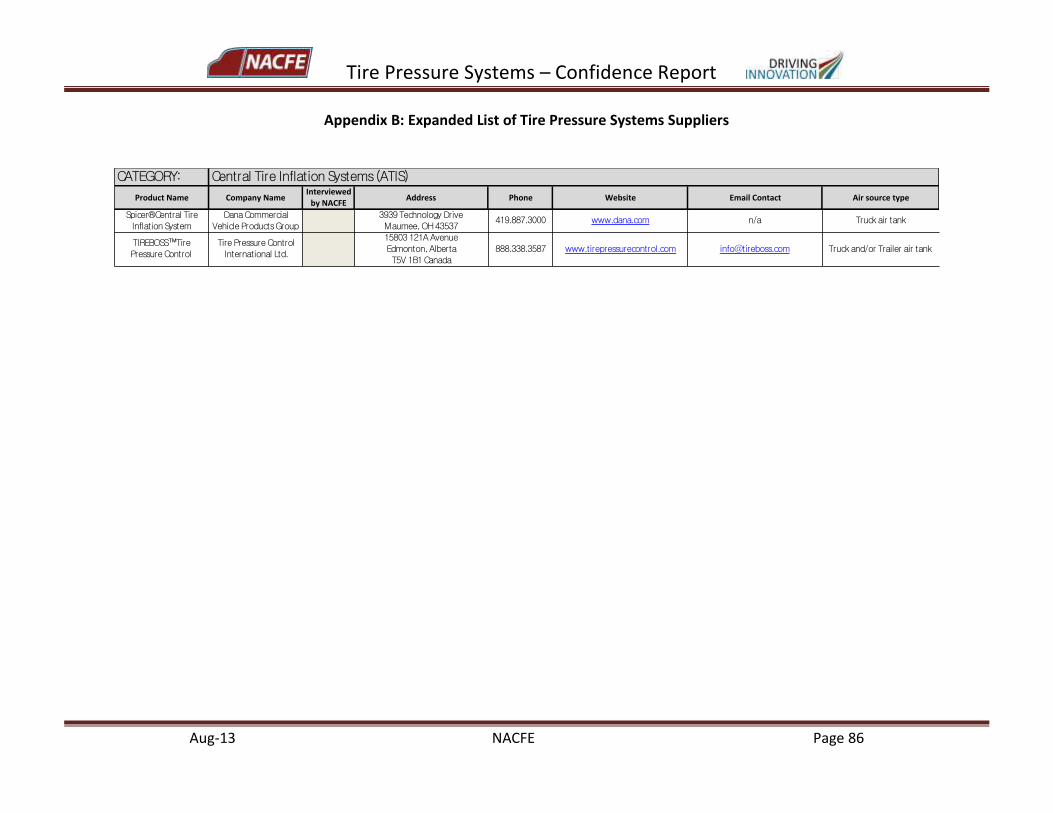
Tire Pressure Systems – Confidence Report
Aug-13 NACFE Page 86
Appendix B: Expanded List of Tire Pressure Systems Suppliers
CATEGORY:
ProductName CompanyNameInterviewed
byNACFEAddress Phone Website EmailContact Airsourcetype
Spicer®CentralTire
InflationSystem
DanaCommercial
VehicleProductsGroup
3939TechnologyDrive
Maumee,OH43537419.887.3000 www.dana.com n/a Truckairtank
TIREBOSS™TirePressureControl
TirePressureControlInternationalLtd.
15803121AAvenue
Edmonton,Alberta
T5V1B1Canada
888.338.3587 www.tirepressurecontrol.com [email protected] Truckand/orTrailerairtank
CentralTireInflationSystems(ATIS)
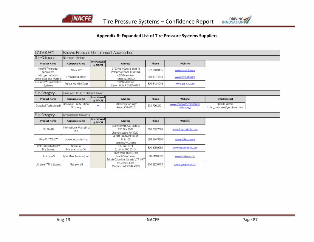
Tire Pressure Systems – Confidence Report
Aug-13 NACFE Page 87
Appendix B: Expanded List of Tire Pressure Systems Suppliers
CATEGORY:Sub-Category:
ProductName CompanyNameInterviewed
byNACFEAddress Phone Website
NitroFill™nitrogen
generatorsNitroFill™
3750ParkCentralBlvd.N
PompanoBeach,FL33064877.246.3455 www.nitrofill.com
NitrogenInflation
Towers(variousmodels)BranickIndustries
4245MainAve.
Fargo,NC58103800.437.4394 www.branick.com
TireSaver™TireInflation
SystemsParkerHannifinCorp
242NeckRoad
Haverhill,MA01835-0723800.343.4048 www.parker.com
Sub-Category:
ProductName CompanyNameInterviewed
byNACFEAddress Phone Website EmailContact
DuraSealTechnology®GoodyearTire&Rubber
Company*
200InnovationWay
Akron,OH44316330.796.2121
www.goodyear.com/truck/
technology
BrianBuckham
Sub-Category:
ProductName CompanyNameInterviewed
byNACFEAddress Phone Website
EcoSeal®InternationalMarketing
Inc.
25PenncraftAve,SuiteC
P.O.Box2002
Chambersburg,PA17201
800.233.7086 www.imiproducts.com
Ride-On™CHS™ InovexIndustriesInc.45681OakbrookCourt
Unit102
Sterling,VA20166
888.374.3366 www.ride-on.com
#743SchaefferSeal™TireSealant
SchaefferManufacturingCo.
102BartonStSt.Louis,MO63104
800.325.9962 www.schaefferoil.com
TireLyna® LynaManufacturingInc.
1125West15thStreet
NorthVancouver
BritishColumbia,CanadaV7P1M7
888.619.6669 www.tirelyna.com
Ultraseal™TireSealant Gempler's®P.O.Box44993
Madison,WI53744-4993800.382.8473 www.gemplers.com
AftermarketSealants
PassivePressureContainmentApproachesNitrogenInflation
TireswithBuilt-InSealantLayer
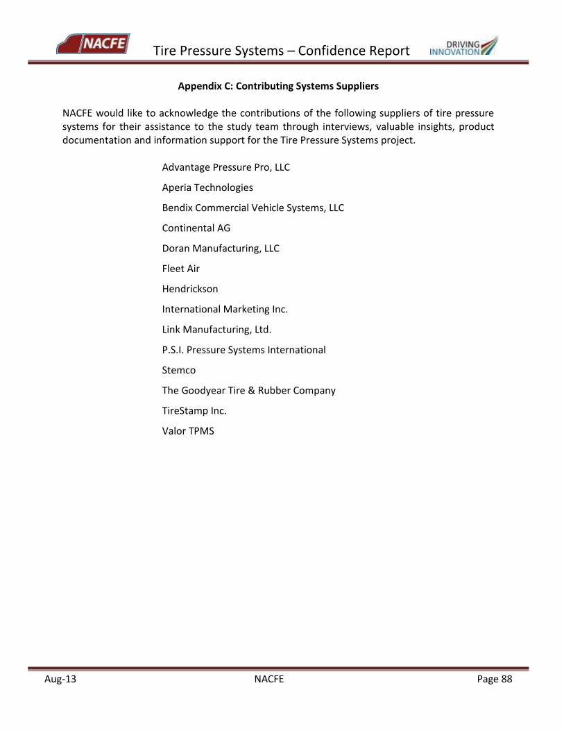
Tire Pressure Systems – Confidence Report
Aug-13 NACFE Page 88
Appendix C: Contributing Systems Suppliers
NACFE would like to acknowledge the contributions of the following suppliers of tire pressure systems for their assistance to the study team through interviews, valuable insights, product documentation and information support for the Tire Pressure Systems project.
Advantage Pressure Pro, LLC
Aperia Technologies
Bendix Commercial Vehicle Systems, LLC
Continental AG
Doran Manufacturing, LLC
Fleet Air
Hendrickson
International Marketing Inc.
Link Manufacturing, Ltd.
P.S.I. Pressure Systems International
Stemco
The Goodyear Tire & Rubber Company
TireStamp Inc.
Valor TPMS


![Tire Price List [TireOutfitters Toronto Tire Specialist]](https://img.pdfslide.net/doc/110x75/542ceaed219acd4e4b8b4d6e/tire-price-list-tireoutfitters-toronto-tire-specialist.jpg)