Embed Size (px)
Citation preview
Module for Stepper Motors MODULE
TMCM-1021 TMCL™Firmware Manual
Firmware Version V1.42 | Document Revision V1.10 • 2018-JAN-09
The TMCM-1021 is a single axis controller/driver module for 2-phase bipolar stepper motors. The
TMCM-1021 TMCL firmware allows to control the module using TMCL™ commands, supporting
standalone operation as well as direct mode control, making use of the Trinamic TMC262 motor
driver. Dynamic current control, and quiet, smooth and efficient operation are combined with
stallGuard™ and coolStep™ features.
Features
• Single Axis Stepper motor control
• Supply voltage 24V DC
• TMCL™
• RS485 interface
• Step/Direction input
• Additional inputs and outputs
• coolStep™
• stallGuard2™
• sensOstep™ encoder
Applications
• Laboratory Automation
• Manufacturing
• Semiconductor Handling
• Robotics
• Factory Automation
• Test & Measurement
• Life Science
• Biotechnology
• Liquid Handling
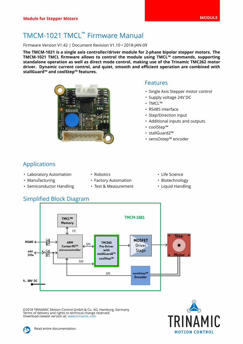
Simplified Block Diagram
9… 28V DC
ARMCortex-M3TM
microcontroller
TMCL™Memory
4add.I/Os
Step
Motor
RS485 MOSFETDriverStage
Energy Efficient
DriverTMC262
TMC262Pre-Driver
withstallGuard2TM
coolStep™
sensOstep™
EncoderSPI
TMCM-1021
S/D
SPI
I2C
©2018 TRINAMIC Motion Control GmbH & Co. KG, Hamburg, Germany
Terms of delivery and rights to technical change reserved.
Download newest version at: www.trinamic.com
Read entire documentation.
TMCM-1021 TMCL™ Firmware Manual • Firmware Version V1.42 | Document Revision V1.10 • 2018-JAN-09 2 / 109
Contents
1 Features 5
1.1 stallGuard2 . . . . . . . . . . . . . . . . . . . . . . . . . . . . . . . . . . . . . . . . . . . . . . . . . 6
1.2 coolStep . . . . . . . . . . . . . . . . . . . . . . . . . . . . . . . . . . . . . . . . . . . . . . . . . . 6
2 First Steps with TMCL 7
2.1 Basic Setup . . . . . . . . . . . . . . . . . . . . . . . . . . . . . . . . . . . . . . . . . . . . . . . . . 7
2.2 Using the TMCL Direct Mode . . . . . . . . . . . . . . . . . . . . . . . . . . . . . . . . . . . . . . 7
2.3 Changing Axis Parameters . . . . . . . . . . . . . . . . . . . . . . . . . . . . . . . . . . . . . . . . 7
2.4 Testing with a simple TMCL Program . . . . . . . . . . . . . . . . . . . . . . . . . . . . . . . . . . 8
3 TMCL and the TMCL-IDE— An Introduction 10
3.1 Binary Command Format . . . . . . . . . . . . . . . . . . . . . . . . . . . . . . . . . . . . . . . . 10
3.1.1 Checksum Calculation . . . . . . . . . . . . . . . . . . . . . . . . . . . . . . . . . . . . . . 11
3.2 Reply Format . . . . . . . . . . . . . . . . . . . . . . . . . . . . . . . . . . . . . . . . . . . . . . . 12
3.2.1 Status Codes . . . . . . . . . . . . . . . . . . . . . . . . . . . . . . . . . . . . . . . . . . . 12
3.3 Standalone Applications . . . . . . . . . . . . . . . . . . . . . . . . . . . . . . . . . . . . . . . . . 13
3.4 The ASCII Interface . . . . . . . . . . . . . . . . . . . . . . . . . . . . . . . . . . . . . . . . . . . . 14
3.4.1 Entering and leaving the ASCIIMode . . . . . . . . . . . . . . . . . . . . . . . . . . . . . 14
3.4.2 Format of the Command Line . . . . . . . . . . . . . . . . . . . . . . . . . . . . . . . . . 14
3.4.3 Format of a Reply . . . . . . . . . . . . . . . . . . . . . . . . . . . . . . . . . . . . . . . . . 15
3.4.4 Configuring the ASCII Interface . . . . . . . . . . . . . . . . . . . . . . . . . . . . . . . . . 15
3.5 TMCL Command Overview . . . . . . . . . . . . . . . . . . . . . . . . . . . . . . . . . . . . . . . 16
3.5.1 TMCL Commands . . . . . . . . . . . . . . . . . . . . . . . . . . . . . . . . . . . . . . . . . 16
3.6 TMCL Commands by Subject . . . . . . . . . . . . . . . . . . . . . . . . . . . . . . . . . . . . . . 17
3.6.1 Motion Commands . . . . . . . . . . . . . . . . . . . . . . . . . . . . . . . . . . . . . . . . 17
3.6.2 Parameter Commands . . . . . . . . . . . . . . . . . . . . . . . . . . . . . . . . . . . . . . 18
3.6.3 Branch Commands . . . . . . . . . . . . . . . . . . . . . . . . . . . . . . . . . . . . . . . . 18
3.6.4 I/O Port Commands . . . . . . . . . . . . . . . . . . . . . . . . . . . . . . . . . . . . . . . 19
3.6.5 Calculation Commands . . . . . . . . . . . . . . . . . . . . . . . . . . . . . . . . . . . . . 19
3.6.6 Interrupt Processing Commands . . . . . . . . . . . . . . . . . . . . . . . . . . . . . . . . 20
3.7 Detailed TMCL Command Descriptions . . . . . . . . . . . . . . . . . . . . . . . . . . . . . . . . 23
3.7.1 ROR (Rotate Right) . . . . . . . . . . . . . . . . . . . . . . . . . . . . . . . . . . . . . . . . 23
3.7.2 ROL (Rotate Left) . . . . . . . . . . . . . . . . . . . . . . . . . . . . . . . . . . . . . . . . . 24
3.7.3 MST (Motor Stop) . . . . . . . . . . . . . . . . . . . . . . . . . . . . . . . . . . . . . . . . . 25
3.7.4 MVP (Move to Position) . . . . . . . . . . . . . . . . . . . . . . . . . . . . . . . . . . . . . 26
3.7.5 SAP (Set Axis Parameter) . . . . . . . . . . . . . . . . . . . . . . . . . . . . . . . . . . . . 29
3.7.6 GAP (Get Axis Parameter) . . . . . . . . . . . . . . . . . . . . . . . . . . . . . . . . . . . . 30
3.7.7 STAP (Store Axis Parameter) . . . . . . . . . . . . . . . . . . . . . . . . . . . . . . . . . . . 31
3.7.8 RSAP (Restore Axis Parameter) . . . . . . . . . . . . . . . . . . . . . . . . . . . . . . . . . 32
3.7.9 SGP (Set Global Parameter) . . . . . . . . . . . . . . . . . . . . . . . . . . . . . . . . . . . 33
3.7.10 GGP (Get Global Parameter) . . . . . . . . . . . . . . . . . . . . . . . . . . . . . . . . . . 34
3.7.11 STGP (Store Global Parameter) . . . . . . . . . . . . . . . . . . . . . . . . . . . . . . . . . 35
3.7.12 RSGP (Restore Global Parameter) . . . . . . . . . . . . . . . . . . . . . . . . . . . . . . . 36
3.7.13 RFS (Reference Search) . . . . . . . . . . . . . . . . . . . . . . . . . . . . . . . . . . . . . . 37
3.7.14 SIO (Set Output) . . . . . . . . . . . . . . . . . . . . . . . . . . . . . . . . . . . . . . . . . . 39
3.7.15 GIO (Get Input) . . . . . . . . . . . . . . . . . . . . . . . . . . . . . . . . . . . . . . . . . . 41
3.7.16 CALC (Calculate) . . . . . . . . . . . . . . . . . . . . . . . . . . . . . . . . . . . . . . . . . . 44
3.7.17 COMP (Compare) . . . . . . . . . . . . . . . . . . . . . . . . . . . . . . . . . . . . . . . . . 46
3.7.18 JC (Jump conditional) . . . . . . . . . . . . . . . . . . . . . . . . . . . . . . . . . . . . . . . 47
3.7.19 JA (Jump always) . . . . . . . . . . . . . . . . . . . . . . . . . . . . . . . . . . . . . . . . . 49
3.7.20 CSUB (Call Subroutine) . . . . . . . . . . . . . . . . . . . . . . . . . . . . . . . . . . . . . . 50
3.7.21 RSUB (Return from Subroutine) . . . . . . . . . . . . . . . . . . . . . . . . . . . . . . . . 51
©2018 TRINAMIC Motion Control GmbH & Co. KG, Hamburg, Germany
Terms of delivery and rights to technical change reserved.
Download newest version at www.trinamic.com
TMCM-1021 TMCL™ Firmware Manual • Firmware Version V1.42 | Document Revision V1.10 • 2018-JAN-09 3 / 109
3.7.22 WAIT (Wait for an Event to occur) . . . . . . . . . . . . . . . . . . . . . . . . . . . . . . . . 52
3.7.23 STOP (Stop TMCL Program Execution – End of TMCL Program) . . . . . . . . . . . . . . 54
3.7.24 SCO (Set Coordinate) . . . . . . . . . . . . . . . . . . . . . . . . . . . . . . . . . . . . . . . 55
3.7.25 GCO (Get Coordinate) . . . . . . . . . . . . . . . . . . . . . . . . . . . . . . . . . . . . . . 56
3.7.26 CCO (Capture Coordinate) . . . . . . . . . . . . . . . . . . . . . . . . . . . . . . . . . . . . 58
3.7.27 ACO (Accu to Coordinate) . . . . . . . . . . . . . . . . . . . . . . . . . . . . . . . . . . . . 59
3.7.28 CALCX (Calculate using the X Register) . . . . . . . . . . . . . . . . . . . . . . . . . . . . . 60
3.7.29 AAP (Accu to Axis Parameter) . . . . . . . . . . . . . . . . . . . . . . . . . . . . . . . . . . 62
3.7.30 AGP (Accu to Global Parameter) . . . . . . . . . . . . . . . . . . . . . . . . . . . . . . . . 63
3.7.31 CLE (Clear Error Flags) . . . . . . . . . . . . . . . . . . . . . . . . . . . . . . . . . . . . . . 64
3.7.32 EI (Enable Interrupt) . . . . . . . . . . . . . . . . . . . . . . . . . . . . . . . . . . . . . . . 66
3.7.33 DI (Disable Interrupt) . . . . . . . . . . . . . . . . . . . . . . . . . . . . . . . . . . . . . . . 67
3.7.34 VECT (Define Interrupt Vector) . . . . . . . . . . . . . . . . . . . . . . . . . . . . . . . . . 68
3.7.35 RETI (Return from Interrupt) . . . . . . . . . . . . . . . . . . . . . . . . . . . . . . . . . . 70
3.7.36 Customer specific Command Extensions (UF0. . . UF7 – User Functions) . . . . . . . . . 71
3.7.37 Request Target Position reached Event . . . . . . . . . . . . . . . . . . . . . . . . . . . . 72
3.7.38 TMCL Control Commands . . . . . . . . . . . . . . . . . . . . . . . . . . . . . . . . . . . . 74
4 Axis Parameters 76
5 Global Parameters 85
5.1 Bank 0 . . . . . . . . . . . . . . . . . . . . . . . . . . . . . . . . . . . . . . . . . . . . . . . . . . . 85
5.2 Bank 1 . . . . . . . . . . . . . . . . . . . . . . . . . . . . . . . . . . . . . . . . . . . . . . . . . . . 88
5.3 Bank 2 . . . . . . . . . . . . . . . . . . . . . . . . . . . . . . . . . . . . . . . . . . . . . . . . . . . 88
5.4 Bank 3 . . . . . . . . . . . . . . . . . . . . . . . . . . . . . . . . . . . . . . . . . . . . . . . . . . . 88
6 Module Specific Hints 90
6.1 Conversion between PPS, RPM and RPS . . . . . . . . . . . . . . . . . . . . . . . . . . . . . . . . 90
6.2 The sensOstep™ Encoder . . . . . . . . . . . . . . . . . . . . . . . . . . . . . . . . . . . . . . . . 90
6.2.1 Matching Encoder Resolution and Motor Resolution . . . . . . . . . . . . . . . . . . . . 91
6.2.2 Special Encoder Functions . . . . . . . . . . . . . . . . . . . . . . . . . . . . . . . . . . . . 91
7 Hints and Tips 92
7.1 Reference Search . . . . . . . . . . . . . . . . . . . . . . . . . . . . . . . . . . . . . . . . . . . . . 92
7.1.1 Mode 1 . . . . . . . . . . . . . . . . . . . . . . . . . . . . . . . . . . . . . . . . . . . . . . . 93
7.1.2 Mode 2 . . . . . . . . . . . . . . . . . . . . . . . . . . . . . . . . . . . . . . . . . . . . . . . 93
7.1.3 Mode 3 . . . . . . . . . . . . . . . . . . . . . . . . . . . . . . . . . . . . . . . . . . . . . . . 93
7.1.4 Mode 4 . . . . . . . . . . . . . . . . . . . . . . . . . . . . . . . . . . . . . . . . . . . . . . . 94
7.1.5 Mode 5 . . . . . . . . . . . . . . . . . . . . . . . . . . . . . . . . . . . . . . . . . . . . . . . 94
7.1.6 Mode 6 . . . . . . . . . . . . . . . . . . . . . . . . . . . . . . . . . . . . . . . . . . . . . . . 95
7.1.7 Mode 7 . . . . . . . . . . . . . . . . . . . . . . . . . . . . . . . . . . . . . . . . . . . . . . . 95
7.1.8 Mode 8 . . . . . . . . . . . . . . . . . . . . . . . . . . . . . . . . . . . . . . . . . . . . . . . 96
7.2 stallGuard2 . . . . . . . . . . . . . . . . . . . . . . . . . . . . . . . . . . . . . . . . . . . . . . . . . 97
7.3 coolStep . . . . . . . . . . . . . . . . . . . . . . . . . . . . . . . . . . . . . . . . . . . . . . . . . . 98
8 TMCL Programming Techniques and Structure 100
8.1 Initialization . . . . . . . . . . . . . . . . . . . . . . . . . . . . . . . . . . . . . . . . . . . . . . . . 100
8.2 Main Loop . . . . . . . . . . . . . . . . . . . . . . . . . . . . . . . . . . . . . . . . . . . . . . . . . 100
8.3 Using Symbolic Constants . . . . . . . . . . . . . . . . . . . . . . . . . . . . . . . . . . . . . . . . 100
8.4 Using Variables . . . . . . . . . . . . . . . . . . . . . . . . . . . . . . . . . . . . . . . . . . . . . . 101
8.5 Using Subroutines . . . . . . . . . . . . . . . . . . . . . . . . . . . . . . . . . . . . . . . . . . . . 102
8.6 Combining Direct Mode and Standalone Mode . . . . . . . . . . . . . . . . . . . . . . . . . . . 102
8.7 Make the TMCL Program start automatically . . . . . . . . . . . . . . . . . . . . . . . . . . . . . 103
9 Figures Index 104
©2018 TRINAMIC Motion Control GmbH & Co. KG, Hamburg, Germany
Terms of delivery and rights to technical change reserved.
Download newest version at www.trinamic.com
TMCM-1021 TMCL™ Firmware Manual • Firmware Version V1.42 | Document Revision V1.10 • 2018-JAN-09 4 / 109
10 Tables Index 105
11 Supplemental Directives 106
11.1 Producer Information . . . . . . . . . . . . . . . . . . . . . . . . . . . . . . . . . . . . . . . . . . 106
11.2 Copyright . . . . . . . . . . . . . . . . . . . . . . . . . . . . . . . . . . . . . . . . . . . . . . . . . . 106
11.3 Trademark Designations and Symbols . . . . . . . . . . . . . . . . . . . . . . . . . . . . . . . . . 106
11.4 Target User . . . . . . . . . . . . . . . . . . . . . . . . . . . . . . . . . . . . . . . . . . . . . . . . . 106
11.5 Disclaimer: Life Support Systems . . . . . . . . . . . . . . . . . . . . . . . . . . . . . . . . . . . . 106
11.6 Disclaimer: Intended Use . . . . . . . . . . . . . . . . . . . . . . . . . . . . . . . . . . . . . . . . 106
11.7 Collateral Documents & Tools . . . . . . . . . . . . . . . . . . . . . . . . . . . . . . . . . . . . . . 107
12 Revision History 108
12.1 Firmware Revision . . . . . . . . . . . . . . . . . . . . . . . . . . . . . . . . . . . . . . . . . . . . 108
12.2 Document Revision . . . . . . . . . . . . . . . . . . . . . . . . . . . . . . . . . . . . . . . . . . . . 109
©2018 TRINAMIC Motion Control GmbH & Co. KG, Hamburg, Germany
Terms of delivery and rights to technical change reserved.
Download newest version at www.trinamic.com
TMCM-1021 TMCL™ Firmware Manual • Firmware Version V1.42 | Document Revision V1.10 • 2018-JAN-09 5 / 109
1 Features
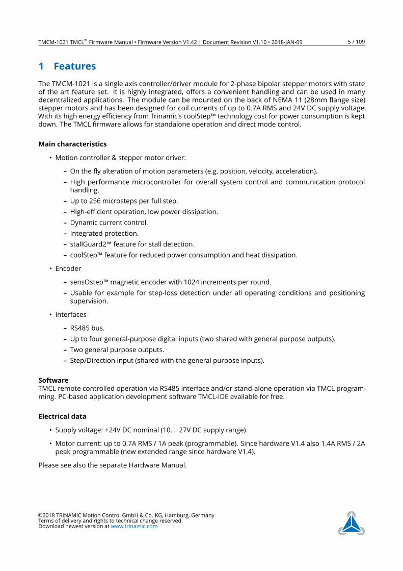
The TMCM-1021 is a single axis controller/driver module for 2-phase bipolar stepper motors with state
of the art feature set. It is highly integrated, offers a convenient handling and can be used in many
decentralized applications. The module can be mounted on the back of NEMA 11 (28mm flange size)
stepper motors and has been designed for coil currents of up to 0.7A RMS and 24V DC supply voltage.
With its high energy efficiency from Trinamic’s coolStep™ technology cost for power consumption is kept
down. The TMCL firmware allows for standalone operation and direct mode control.
Main characteristics
• Motion controller & stepper motor driver:
– On the fly alteration of motion parameters (e.g. position, velocity, acceleration).
– High performance microcontroller for overall system control and communication protocol
handling.
– Up to 256 microsteps per full step.
– High-efficient operation, low power dissipation.
– Dynamic current control.
– Integrated protection.
– stallGuard2™ feature for stall detection.
– coolStep™ feature for reduced power consumption and heat dissipation.
• Encoder
– sensOstep™magnetic encoder with 1024 increments per round.
– Usable for example for step-loss detection under all operating conditions and positioning
supervision.
• Interfaces
– RS485 bus.
– Up to four general-purpose digital inputs (two shared with general purpose outputs).
– Two general purpose outputs.
– Step/Direction input (shared with the general purpose inputs).
Software
TMCL remote controlled operation via RS485 interface and/or stand-alone operation via TMCL program-
ming. PC-based application development software TMCL-IDE available for free.
Electrical data
• Supply voltage: +24V DC nominal (10. . . 27V DC supply range).
• Motor current: up to 0.7A RMS / 1A peak (programmable). Since hardware V1.4 also 1.4A RMS / 2A
peak programmable (new extended range since hardware V1.4).
Please see also the separate Hardware Manual.
©2018 TRINAMIC Motion Control GmbH & Co. KG, Hamburg, Germany
Terms of delivery and rights to technical change reserved.
Download newest version at www.trinamic.com
TMCM-1021 TMCL™ Firmware Manual • Firmware Version V1.42 | Document Revision V1.10 • 2018-JAN-09 6 / 109
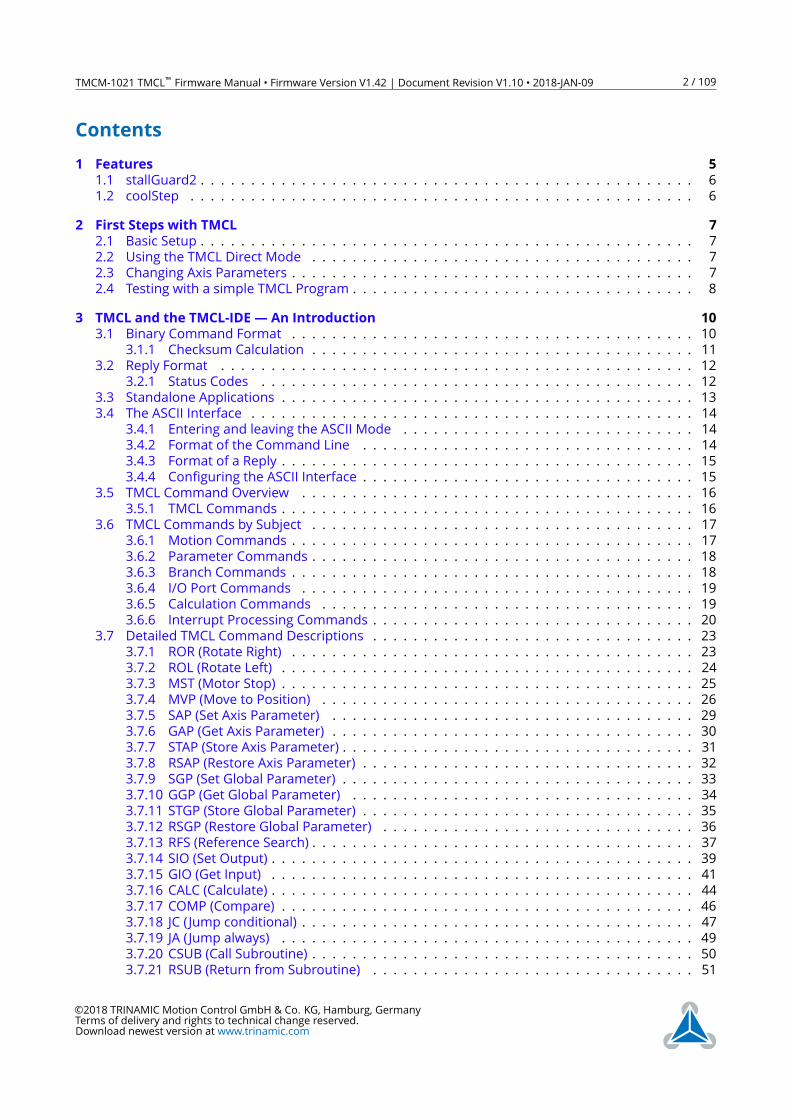
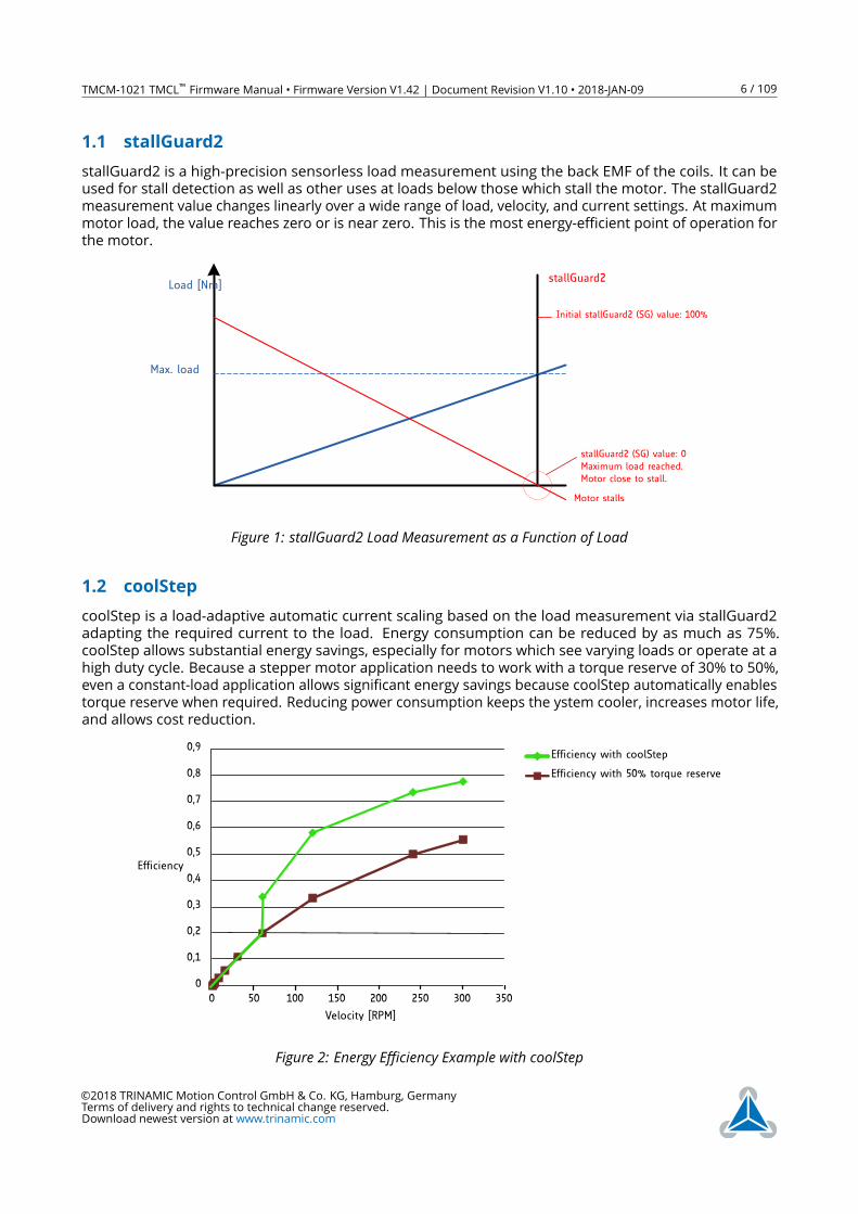
1.1 stallGuard2
stallGuard2 is a high-precision sensorless load measurement using the back EMF of the coils. It can be
used for stall detection as well as other uses at loads below those which stall the motor. The stallGuard2
measurement value changes linearly over a wide range of load, velocity, and current settings. At maximum
motor load, the value reaches zero or is near zero. This is the most energy-efficient point of operation for
the motor.
Load [Nm]stallGuard2
Initial stallGuard2 (SG) value: 100%
Max. load
stallGuard2 (SG) value: 0Maximum load reached.Motor close to stall.
Motor stalls
Figure 1: stallGuard2 Load Measurement as a Function of Load
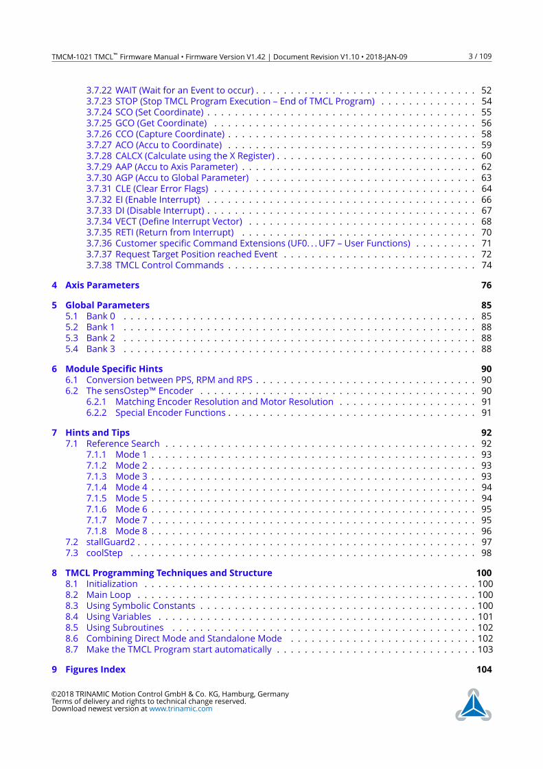
1.2 coolStep
coolStep is a load-adaptive automatic current scaling based on the load measurement via stallGuard2
adapting the required current to the load. Energy consumption can be reduced by as much as 75%.
coolStep allows substantial energy savings, especially for motors which see varying loads or operate at a
high duty cycle. Because a stepper motor application needs to work with a torque reserve of 30% to 50%,
even a constant-load application allows significant energy savings because coolStep automatically enables
torque reserve when required. Reducing power consumption keeps the ystem cooler, increases motor life,
and allows cost reduction.
0
0,1
0,2
0,3
0,4
0,5
0,6
0,7
0,8
0,9
0 50 100 150 200 250 300 350
Efficiency
Velocity [RPM]
Efficiency with coolStep
Efficiency with 50v torque reserve
Figure 2: Energy Efficiency Example with coolStep
©2018 TRINAMIC Motion Control GmbH & Co. KG, Hamburg, Germany
Terms of delivery and rights to technical change reserved.
Download newest version at www.trinamic.com
TMCM-1021 TMCL™ Firmware Manual • Firmware Version V1.42 | Document Revision V1.10 • 2018-JAN-09 7 / 109
2 First Steps with TMCL
In this chapter you can find some hints for your first steps with the TMCM-1021 and TMCL. You may skip
this chapter if you are already familiar with TMCL and the TMCL-IDE.
Things that you will need
• Your TMCM-1021 module.
• An RS485 interface connected to your PC.
• A power supply (24V DC) for your TMCM-1021 module.
• The TMCL-IDE 3.x already installed on your PC.
• A two-phase bipolar stepper motor.
2.1 Basic Setup
First of all, you will need a PC with Windows (at least Windows 7) and the TMCL-IDE 3.x installed on it. If
you do not have the TMCL-IDE installed on your PC then please download it from the TMCL-IDE product
page of Trinamic’s website (http://www.trinamic.com) and install it on your PC.
Please also ensure that your TMCM-1021 is properly connected to your power supply and that the stepper
motor is properly connected to the module. Please see the TMCM-1021 hardware manual for instructions
on how to do this. Do not connect or disconnect a stepper motor to or from the module while the
module is powered!
Then, please start up the TMCL-IDE. After that you can connect your TMCM-1021 via RS485 and switch
on the power supply for the module (while the TMCL-IDE is running on your PC). When the module is
connected properly via RS485 then it will be recognized by the TMCL-IDE so that it can be used.
2.2 Using the TMCL Direct Mode
At first try to use some TMCL commands in direct mode. In the TMCL-IDE a tree view showing the TMCM-
1021 and all tools available for it is displayed. Click on the Direct Mode entry of the tool tree. Now, the
Direct Mode tool will pop up.
In the Direct Mode tool you can choose a TMCL command, enter the necessary parameters and execute
the command. For example, choose the command ROL (rotate left). Then choose the appropriate motor
(motor 0 if your motor is connected to the motor 0 connector). Now, enter the desired speed. Try entering
51200 (pps) as the value and then click the Execute button. The motor will now run.
Choose the MST (motor stop) command and click Execute again to stop the motor.
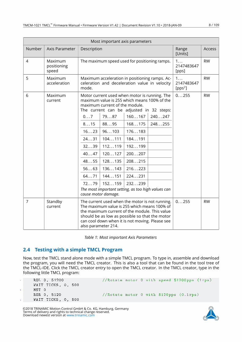
2.3 Changing Axis Parameters
Next you can try changing some settings (also called axis parameters) using the SAP command in direct
mode. Choose the SAP command. Then choose the parameter type and the motor number. Last, enter
the desired value and click execute to execute the command which then changes the desired parameter.
The following table points out the most important axis parameters. Please see chapter 4 for a complete
list of all axis parameters.
©2018 TRINAMIC Motion Control GmbH & Co. KG, Hamburg, Germany
Terms of delivery and rights to technical change reserved.
Download newest version at www.trinamic.com
TMCM-1021 TMCL™ Firmware Manual • Firmware Version V1.42 | Document Revision V1.10 • 2018-JAN-09 8 / 109
Most important axis parameters
Number Axis Parameter Description Range
[Units]
Access
4 Maximum
positioning
speed
Themaximum speed used for positioning ramps. 1. . .
2147483647
[pps]
RW
5 Maximum
acceleration
Maximum acceleration in positioning ramps. Ac-
celeration and deceleration value in velocity
mode.
1. . .
2147483647
[pps2]
RW
6 Maximum
current
Motor current used when motor is running. The
maximum value is 255 which means 100% of the
maximum current of the module.
The current can be adjusted in 32 steps:
0. . . 7 79. . . 87 160. . . 167 240. . . 247
8. . . 15 88. . . 95 168. . . 175 248. . . 255
16. . . 23 96. . . 103 176. . . 183
24. . . 31 104. . . 111 184. . . 191
32. . . 39 112. . . 119 192. . . 199
40. . . 47 120. . . 127 200. . . 207
48. . . 55 128. . . 135 208. . . 215
56. . . 63 136. . . 143 216. . . 223
64. . . 71 144. . . 151 224. . . 231
72. . . 79 152. . . 159 232. . . 239
The most important setting, as too high values cancause motor damage.
0. . . 255 RW
7 Standby
current
The current used when the motor is not running.
The maximum value is 255 which means 100% of
the maximum current of the module. This value
should be as low as possible so that the motor
can cool down when it is not moving. Please see
also parameter 214.
0. . . 255 RW
Table 1: Most important Axis Parameters
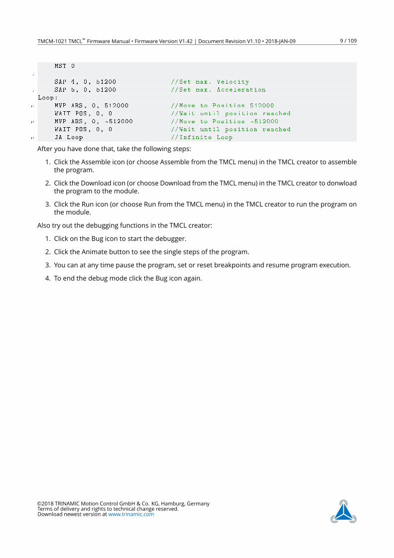
2.4 Testing with a simple TMCL Program
Now, test the TMCL stand alone mode with a simple TMCL program. To type in, assemble and download
the program, you will need the TMCL creator. This is also a tool that can be found in the tool tree of
the TMCL-IDE. Click the TMCL creator entry to open the TMCL creator. In the TMCL creator, type in the
following little TMCL program:
1 ROL 0, 51200 // Rotate motor 0 with speed 51200 pps (1rps)
WAIT TICKS , 0, 500
3 MST 0
ROR 0, 5120 // Rotate motor 0 with 5120 pps (0.1 rps)
5 WAIT TICKS , 0, 500
©2018 TRINAMIC Motion Control GmbH & Co. KG, Hamburg, Germany
Terms of delivery and rights to technical change reserved.
Download newest version at www.trinamic.com
TMCM-1021 TMCL™ Firmware Manual • Firmware Version V1.42 | Document Revision V1.10 • 2018-JAN-09 9 / 109
MST 0
7
SAP 4, 0, 51200 //Set max. Velocity
9 SAP 5, 0, 51200 //Set max. Acceleration
Loop:
11 MVP ABS , 0, 512000 //Move to Position 512000
WAIT POS , 0, 0 //Wait until position reached
13 MVP ABS , 0, -512000 //Move to Position -512000
WAIT POS , 0, 0 //Wait until position reached
15 JA Loop // Infinite Loop
After you have done that, take the following steps:
1. Click the Assemble icon (or choose Assemble from the TMCL menu) in the TMCL creator to assemble
the program.
2. Click the Download icon (or choose Download from the TMCL menu) in the TMCL creator to donwload
the program to the module.
3. Click the Run icon (or choose Run from the TMCL menu) in the TMCL creator to run the program on
the module.
Also try out the debugging functions in the TMCL creator:
1. Click on the Bug icon to start the debugger.
2. Click the Animate button to see the single steps of the program.
3. You can at any time pause the program, set or reset breakpoints and resume program execution.
4. To end the debug mode click the Bug icon again.
©2018 TRINAMIC Motion Control GmbH & Co. KG, Hamburg, Germany
Terms of delivery and rights to technical change reserved.
Download newest version at www.trinamic.com
TMCM-1021 TMCL™ Firmware Manual • Firmware Version V1.42 | Document Revision V1.10 • 2018-JAN-09 10 / 109
3 TMCL and the TMCL-IDE— An Introduction
As with most TRINAMIC modules the software running on the microprocessor of the TMCM-1021 consists
of two parts, a boot loader and the firmware itself. Whereas the boot loader is installed during production
and testing at TRINAMIC and remains untouched throughout the whole lifetime, the firmware can be
updated by the user. New versions can be downloaded free of charge from the TRINAMIC website
(http://www.trinamic.com).
The TMCM-1021 supports TMCL direct mode (binary commands). It also implements standalone TMCL
program execution. This makes it possible to write TMCL programs using the TMCL-IDE and store them in
the memory of the module.
In direct mode the TMCL communication over RS-232, RS-485, CAN and USB follows a strict master/slave
relationship. That is, a host computer (e.g. PC/PLC) acting as the interface bus master will send a command
to the TMCM-1021. The TMCL interpreter on the module will then interpret this command, do the
initialization of the motion controller, read inputs and write outputs or whatever is necessary according to
the specified command. As soon as this step has been done, the module will send a reply back over the
interface to the bus master. Only then should the master transfer the next command.
Normally, the module will just switch to transmission and occupy the bus for a reply, otherwise it will stay
in receive mode. It will not send any data over the interface without receiving a command first. This way,
any collision on the bus will be avoided when there are more than two nodes connected to a single bus.
The Trinamic Motion Control Language [TMCL] provides a set of structured motion control commands.
Every motion control command can be given by a host computer or can be stored in an EEPROM on the
TMCM module to form programs that run standalone on the module. For this purpose there are not only
motion control commands but also commands to control the program structure (like conditional jumps,
compare and calculating).
Every command has a binary representation and a mnemonic. The binary format is used to send com-
mands from the host to a module in direct mode, whereas the mnemonic format is used for easy usage of
the commands when developing standalone TMCL applications using the TMCL-IDE (IDE means Integrated
Development Environment).
There is also a set of configuration variables for the axis and for global parameters which allow individual
configuration of nearly every function of a module. This manual gives a detailed description of all TMCL
commands and their usage.
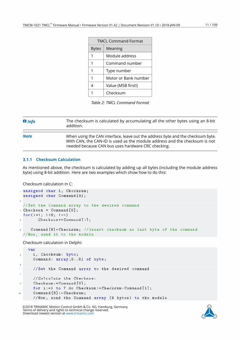
3.1 Binary Command Format
Every command has a mnemonic and a binary representation. When commands are sent from a host
to a module, the binary format has to be used. Every command consists of a one-byte command field, a
one-byte type field, a one-byte motor/bank field and a four-byte value field. So the binary representation
of a command always has seven bytes. When a command is to be sent via RS-232, RS-485, RS-422 or USB
interface, it has to be enclosed by an address byte at the beginning and a checksum byte at the end. In
these cases it consists of nine bytes.
The binary command format with RS-232, RS-485, RS-422 and USB is as follows:
©2018 TRINAMIC Motion Control GmbH & Co. KG, Hamburg, Germany
Terms of delivery and rights to technical change reserved.
Download newest version at www.trinamic.com
TMCM-1021 TMCL™ Firmware Manual • Firmware Version V1.42 | Document Revision V1.10 • 2018-JAN-09 11 / 109
TMCL Command Format
Bytes Meaning
1 Module address
1 Command number
1 Type number
1 Motor or Bank number
4 Value (MSB first!)
1 Checksum
Table 2: TMCL Command Format
Info The checksum is calculated by accumulating all the other bytes using an 8-bit
addition.
Note When using the CAN interface, leave out the address byte and the checksum byte.
With CAN, the CAN-ID is used as the module address and the checksum is not
needed because CAN bus uses hardware CRC checking.
3.1.1 Checksum Calculation
As mentioned above, the checksum is calculated by adding up all bytes (including the module address
byte) using 8-bit addition. Here are two examples which show how to do this:
Checksum calculation in C:
1 unsigned char i, Checksum;
unsigned char Command [9];
3
//Set the Command array to the desired command
5 Checksum = Command [0];
for(i=1; i<8; i++)
7 Checksum += Command[i];
9 Command [8]= Checksum; // insert checksum as last byte of the command
//Now , send it to the module
Checksum calculation in Delphi:
var
2 i, Checksum: byte;
Command: array [0..8] of byte;
4
//Set the Command array to the desired command
6
// Calculate the Checksum:
8 Checksum := Command [0];
for i:=1 to 7 do Checksum := Checksum+Command[i];
10 Command [8]:= Checksum;
//Now , send the Command array (9 bytes) to the module
©2018 TRINAMIC Motion Control GmbH & Co. KG, Hamburg, Germany
Terms of delivery and rights to technical change reserved.
Download newest version at www.trinamic.com
TMCM-1021 TMCL™ Firmware Manual • Firmware Version V1.42 | Document Revision V1.10 • 2018-JAN-09 12 / 109
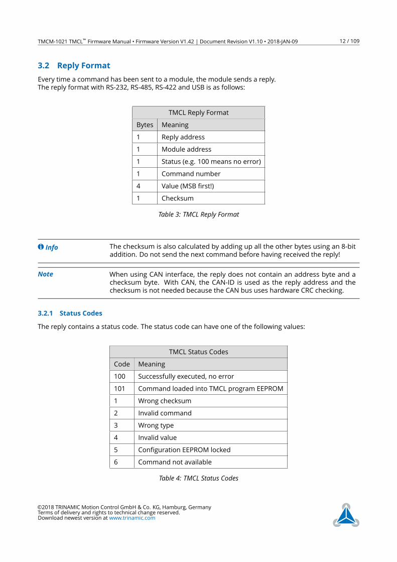
3.2 Reply Format
Every time a command has been sent to a module, the module sends a reply.
The reply format with RS-232, RS-485, RS-422 and USB is as follows:
TMCL Reply Format
Bytes Meaning
1 Reply address
1 Module address
1 Status (e.g. 100 means no error)
1 Command number
4 Value (MSB first!)
1 Checksum
Table 3: TMCL Reply Format
Info The checksum is also calculated by adding up all the other bytes using an 8-bit
addition. Do not send the next command before having received the reply!
Note When using CAN interface, the reply does not contain an address byte and a
checksum byte. With CAN, the CAN-ID is used as the reply address and the
checksum is not needed because the CAN bus uses hardware CRC checking.
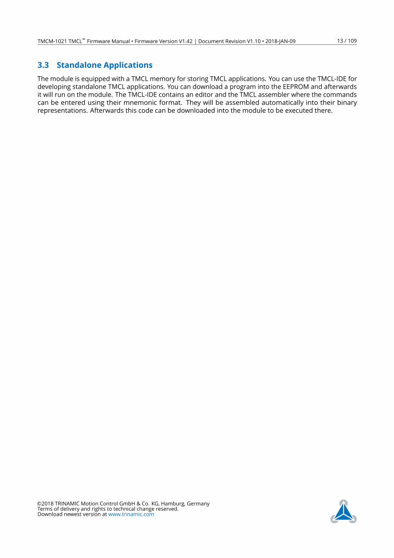
3.2.1 Status Codes
The reply contains a status code. The status code can have one of the following values:
TMCL Status Codes
Code Meaning
100 Successfully executed, no error
101 Command loaded into TMCL program EEPROM
1 Wrong checksum
2 Invalid command
3 Wrong type
4 Invalid value
5 Configuration EEPROM locked
6 Command not available
Table 4: TMCL Status Codes
©2018 TRINAMIC Motion Control GmbH & Co. KG, Hamburg, Germany
Terms of delivery and rights to technical change reserved.
Download newest version at www.trinamic.com
TMCM-1021 TMCL™ Firmware Manual • Firmware Version V1.42 | Document Revision V1.10 • 2018-JAN-09 13 / 109
3.3 Standalone Applications
The module is equipped with a TMCL memory for storing TMCL applications. You can use the TMCL-IDE for
developing standalone TMCL applications. You can download a program into the EEPROM and afterwards
it will run on the module. The TMCL-IDE contains an editor and the TMCL assembler where the commands
can be entered using their mnemonic format. They will be assembled automatically into their binary
representations. Afterwards this code can be downloaded into the module to be executed there.
©2018 TRINAMIC Motion Control GmbH & Co. KG, Hamburg, Germany
Terms of delivery and rights to technical change reserved.
Download newest version at www.trinamic.com
TMCM-1021 TMCL™ Firmware Manual • Firmware Version V1.42 | Document Revision V1.10 • 2018-JAN-09 14 / 109
3.4 The ASCII Interface
There is also an ASCII interface that can be used to communicate with the module and to send some direct
mode commands as text strings. Only the following commands can be used in ASCIImode: ROL, ROR,
MST, MVP, SAP, GAP, STAP, RSAP, SGP, GGP, STGP, RSGP, RFS, SIO, GIO, SCO, GCO, CCO, UF0, UF1, UF2, UF3,
UF4, UF5, UF6, UF7.
Note Only direct mode commands can be entered in ASCIImode.
Note The TMCL-IDE does not support communicating with the module in ASCIImode.
So, in order to be able to use the TMCL-IDE with a module the module must be
in binary mode. We normally recommend using the binary mode as this has
some advantages over the ASCIImode. The ASCIImode is only provided here for
compatibility. For new applications it is strongly recommended to use the binary
mode.
There are also some special commands that are only available in ASCIImode:
• BIN: This command quits ASCIImode and returns to binary mode.
• RUN: This command can be used to start a TMCL program stored in memory.
• STOP: Stops a TMCL program which is currently running on the module.
3.4.1 Entering and leaving the ASCIIMode
• The ASCII command line interface is entered by sending the binary command 139 (enter ASCIImode).
• Afterwards the commands can be entered in their mnemonic form (e.g. via a terminal program).
• For leaving the ASCIImode and re-entering the binary mode enter the command BIN.
3.4.2 Format of the Command Line
As the first character, the address character has to be sent. The address character is A when the module
address is 1, B for modules with address 2 and so on. After the address character there may be spaces
(but this is not necessary). Then, send the command with its parameters. At the end of a command line a
<CR> character has to be sent. Here are some examples for valid ASCIImode command lines (assuming
that the module address is 1):
• AMVP ABS, 1, 50000
• A MVP ABS, 1, 50000
• AROL 2, 500
• A MST 1
• ABIN
The last command line shown above will make the module return to binary mode.
©2018 TRINAMIC Motion Control GmbH & Co. KG, Hamburg, Germany
Terms of delivery and rights to technical change reserved.
Download newest version at www.trinamic.com
TMCM-1021 TMCL™ Firmware Manual • Firmware Version V1.42 | Document Revision V1.10 • 2018-JAN-09 15 / 109
3.4.3 Format of a Reply
After executing the command the module sends back a reply in ASCII format which consists of the following
things:
• The address character of the host (host address that can be set in the module) .
• The address character of the module.
• The status code as a decimal number.
• The return value of the command as a decimal number.
• A <CR> character.
So, after sending AGAP 0, 1 the reply would be BA 100 -5000 if the actual position of axis 1 is -5000, the
host address is set to 2 and the module address is 1. The value 100 is the status code 100 which means
that the command has been executed successfully.
3.4.4 Configuring the ASCII Interface
The module can be configured so that it starts up either in binary mode or in ASCIImode. Global parameter
67 is used for this purpose (please see also chapter 5).
• Bit 0 determines the startup mode: if this bit is set, the module will start up in ASCIImode, else the
module will start up in binary mode (default).
• Bit 4 and bit 5 determine how the characters that are entered are echoed back. Normally, both bits
are set to zero. In this case every character that is entered will be echoed back when the module is
addressed. Characters can also be erased using the backspace character (press the backspace key in
a terminal program).
• When bit 4 is set and bit 5 is clear the characters that are entered are not echoed back immediately
but the entire line will be echoed back after the <CR> character has been sent.
• When bit 5 is set and bit 4 is clear there will be no echo, only the reply will be sent. This may be useful
in RS485 systems.
Note When trying the ASCIImode for the first time it is strongly recommended not to
use global parameter 67 but the direct mode command 139 to enter the ASCII
mode. Then the module can also be switched back to binary mode by a power
cycle if there should be trouble with the ASCIImode communication.
©2018 TRINAMIC Motion Control GmbH & Co. KG, Hamburg, Germany
Terms of delivery and rights to technical change reserved.
Download newest version at www.trinamic.com
TMCM-1021 TMCL™ Firmware Manual • Firmware Version V1.42 | Document Revision V1.10 • 2018-JAN-09 16 / 109
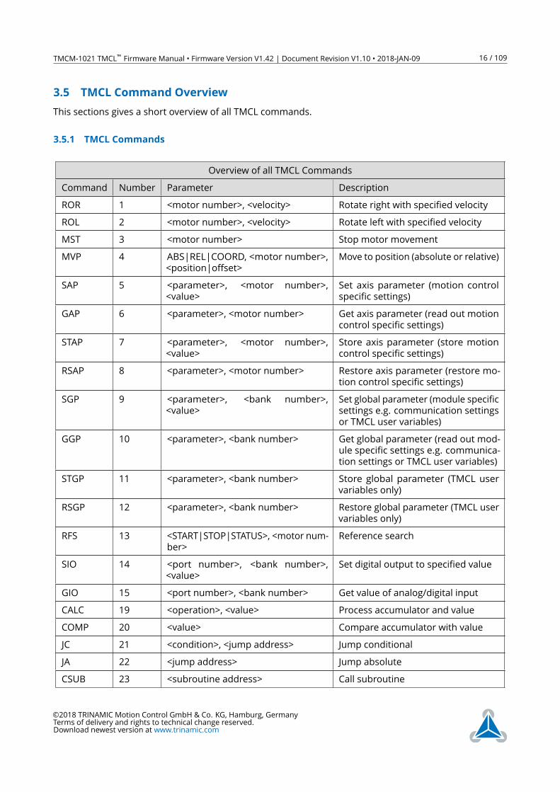
3.5 TMCL Command Overview
This sections gives a short overview of all TMCL commands.
3.5.1 TMCL Commands
Overview of all TMCL Commands
Command Number Parameter Description
ROR 1 <motor number>, <velocity> Rotate right with specified velocity
ROL 2 <motor number>, <velocity> Rotate left with specified velocity
MST 3 <motor number> Stop motor movement
MVP 4 ABS|REL|COORD, <motor number>,
<position|offset>
Move to position (absolute or relative)
SAP 5 <parameter>, <motor number>,
<value>
Set axis parameter (motion control
specific settings)
GAP 6 <parameter>, <motor number> Get axis parameter (read out motion
control specific settings)
STAP 7 <parameter>, <motor number>,
<value>
Store axis parameter (store motion
control specific settings)
RSAP 8 <parameter>, <motor number> Restore axis parameter (restore mo-
tion control specific settings)
SGP 9 <parameter>, <bank number>,
<value>
Set global parameter (module specific
settings e.g. communication settings
or TMCL user variables)
GGP 10 <parameter>, <bank number> Get global parameter (read out mod-
ule specific settings e.g. communica-
tion settings or TMCL user variables)
STGP 11 <parameter>, <bank number> Store global parameter (TMCL user
variables only)
RSGP 12 <parameter>, <bank number> Restore global parameter (TMCL user
variables only)
RFS 13 <START|STOP|STATUS>, <motor num-
ber>
Reference search
SIO 14 <port number>, <bank number>,
<value>
Set digital output to specified value
GIO 15 <port number>, <bank number> Get value of analog/digital input
CALC 19 <operation>, <value> Process accumulator and value
COMP 20 <value> Compare accumulator with value
JC 21 <condition>, <jump address> Jump conditional
JA 22 <jump address> Jump absolute
CSUB 23 <subroutine address> Call subroutine
©2018 TRINAMIC Motion Control GmbH & Co. KG, Hamburg, Germany
Terms of delivery and rights to technical change reserved.
Download newest version at www.trinamic.com
TMCM-1021 TMCL™ Firmware Manual • Firmware Version V1.42 | Document Revision V1.10 • 2018-JAN-09 17 / 109
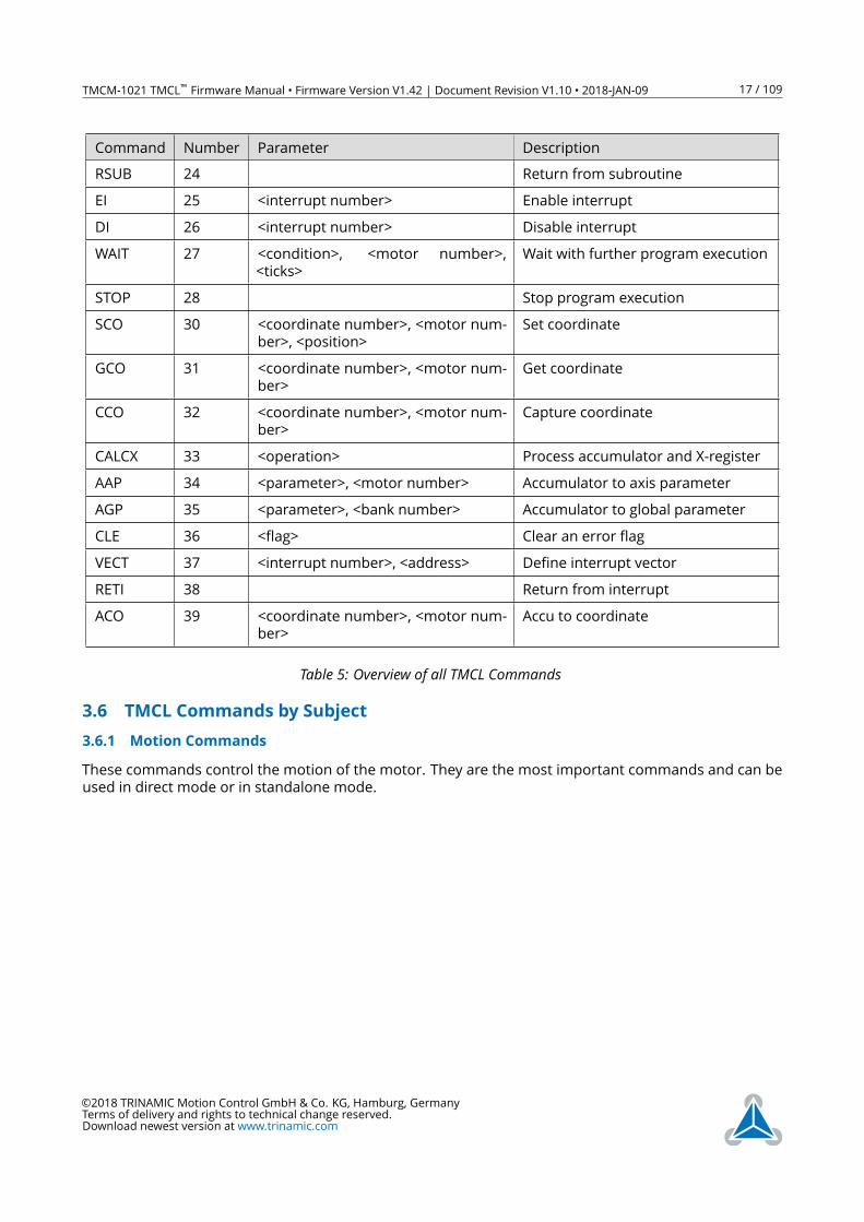
Command Number Parameter Description
RSUB 24 Return from subroutine
EI 25 <interrupt number> Enable interrupt
DI 26 <interrupt number> Disable interrupt
WAIT 27 <condition>, <motor number>,
<ticks>
Wait with further program execution
STOP 28 Stop program execution
SCO 30 <coordinate number>, <motor num-
ber>, <position>
Set coordinate
GCO 31 <coordinate number>, <motor num-
ber>
Get coordinate
CCO 32 <coordinate number>, <motor num-
ber>
Capture coordinate
CALCX 33 <operation> Process accumulator and X-register
AAP 34 <parameter>, <motor number> Accumulator to axis parameter
AGP 35 <parameter>, <bank number> Accumulator to global parameter
CLE 36 <flag> Clear an error flag
VECT 37 <interrupt number>, <address> Define interrupt vector
RETI 38 Return from interrupt
ACO 39 <coordinate number>, <motor num-
ber>
Accu to coordinate
Table 5: Overview of all TMCL Commands
3.6 TMCL Commands by Subject
3.6.1 Motion Commands
These commands control the motion of the motor. They are the most important commands and can be
used in direct mode or in standalone mode.
©2018 TRINAMIC Motion Control GmbH & Co. KG, Hamburg, Germany
Terms of delivery and rights to technical change reserved.
Download newest version at www.trinamic.com
TMCM-1021 TMCL™ Firmware Manual • Firmware Version V1.42 | Document Revision V1.10 • 2018-JAN-09 18 / 109
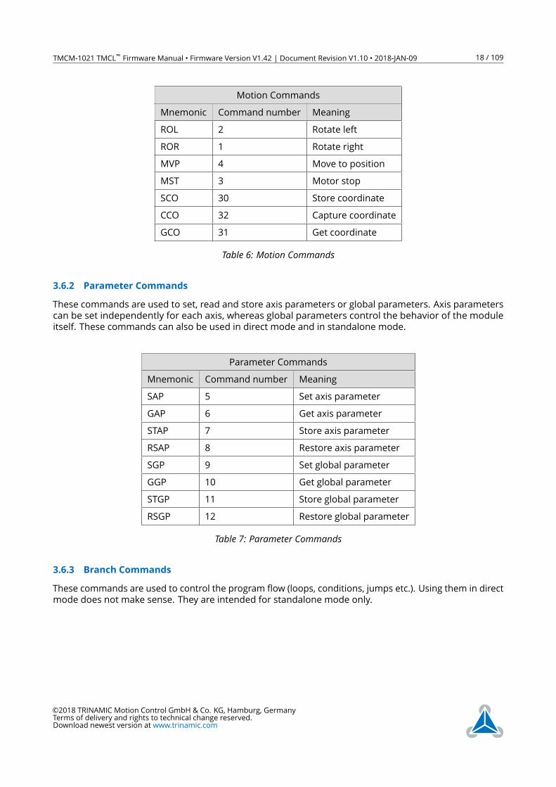
Motion Commands
Mnemonic Command number Meaning
ROL 2 Rotate left
ROR 1 Rotate right
MVP 4 Move to position
MST 3 Motor stop
SCO 30 Store coordinate
CCO 32 Capture coordinate
GCO 31 Get coordinate
Table 6: Motion Commands
3.6.2 Parameter Commands
These commands are used to set, read and store axis parameters or global parameters. Axis parameters
can be set independently for each axis, whereas global parameters control the behavior of the module
itself. These commands can also be used in direct mode and in standalone mode.
Parameter Commands
Mnemonic Command number Meaning
SAP 5 Set axis parameter
GAP 6 Get axis parameter
STAP 7 Store axis parameter
RSAP 8 Restore axis parameter
SGP 9 Set global parameter
GGP 10 Get global parameter
STGP 11 Store global parameter
RSGP 12 Restore global parameter
Table 7: Parameter Commands
3.6.3 Branch Commands
These commands are used to control the program flow (loops, conditions, jumps etc.). Using them in direct
mode does not make sense. They are intended for standalone mode only.
©2018 TRINAMIC Motion Control GmbH & Co. KG, Hamburg, Germany
Terms of delivery and rights to technical change reserved.
Download newest version at www.trinamic.com
TMCM-1021 TMCL™ Firmware Manual • Firmware Version V1.42 | Document Revision V1.10 • 2018-JAN-09 19 / 109
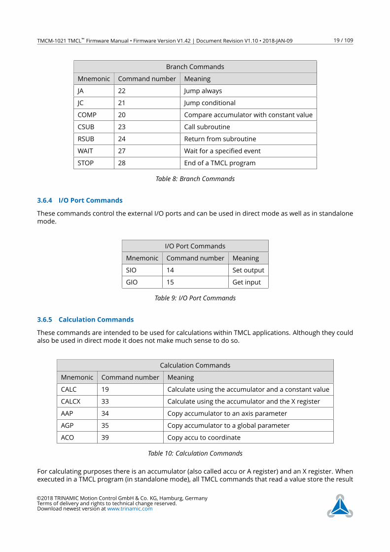
Branch Commands
Mnemonic Command number Meaning
JA 22 Jump always
JC 21 Jump conditional
COMP 20 Compare accumulator with constant value
CSUB 23 Call subroutine
RSUB 24 Return from subroutine
WAIT 27 Wait for a specified event
STOP 28 End of a TMCL program
Table 8: Branch Commands
3.6.4 I/O Port Commands
These commands control the external I/O ports and can be used in direct mode as well as in standalone
mode.
I/O Port Commands
Mnemonic Command number Meaning
SIO 14 Set output
GIO 15 Get input
Table 9: I/O Port Commands
3.6.5 Calculation Commands
These commands are intended to be used for calculations within TMCL applications. Although they could
also be used in direct mode it does not make much sense to do so.
Calculation Commands
Mnemonic Command number Meaning
CALC 19 Calculate using the accumulator and a constant value
CALCX 33 Calculate using the accumulator and the X register
AAP 34 Copy accumulator to an axis parameter
AGP 35 Copy accumulator to a global parameter
ACO 39 Copy accu to coordinate
Table 10: Calculation Commands
For calculating purposes there is an accumulator (also called accu or A register) and an X register. When
executed in a TMCL program (in standalone mode), all TMCL commands that read a value store the result
©2018 TRINAMIC Motion Control GmbH & Co. KG, Hamburg, Germany
Terms of delivery and rights to technical change reserved.
Download newest version at www.trinamic.com
TMCM-1021 TMCL™ Firmware Manual • Firmware Version V1.42 | Document Revision V1.10 • 2018-JAN-09 20 / 109
in the accumulator. The X register can be used as an additional memory when doing calculations. It can be
loaded from the accumulator.
When a command that reads a value is executed in direct mode the accumulator will not be affected.
This means that while a TMCL program is running on the module (standalone mode), a host can still
send commands like GAP and GGP to the module (e.g. to query the actual position of the motor) without
affecting the flow of the TMCL program running on the module.
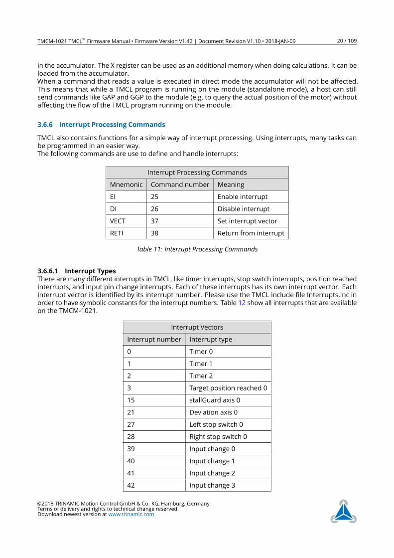
3.6.6 Interrupt Processing Commands
TMCL also contains functions for a simple way of interrupt processing. Using interrupts, many tasks can
be programmed in an easier way.
The following commands are use to define and handle interrupts:
Interrupt Processing Commands
Mnemonic Command number Meaning
EI 25 Enable interrupt
DI 26 Disable interrupt
VECT 37 Set interrupt vector
RETI 38 Return from interrupt
Table 11: Interrupt Processing Commands
3.6.6.1 Interrupt Types
There are many different interrupts in TMCL, like timer interrupts, stop switch interrupts, position reached
interrupts, and input pin change interrupts. Each of these interrupts has its own interrupt vector. Each
interrupt vector is identified by its interrupt number. Please use the TMCL include file Interrupts.inc in
order to have symbolic constants for the interrupt numbers. Table 12 show all interrupts that are available
on the TMCM-1021.
Interrupt Vectors
Interrupt number Interrupt type
0 Timer 0
1 Timer 1
2 Timer 2
3 Target position reached 0
15 stallGuard axis 0
21 Deviation axis 0
27 Left stop switch 0
28 Right stop switch 0
39 Input change 0
40 Input change 1
41 Input change 2
42 Input change 3
©2018 TRINAMIC Motion Control GmbH & Co. KG, Hamburg, Germany
Terms of delivery and rights to technical change reserved.
Download newest version at www.trinamic.com
TMCM-1021 TMCL™ Firmware Manual • Firmware Version V1.42 | Document Revision V1.10 • 2018-JAN-09 21 / 109
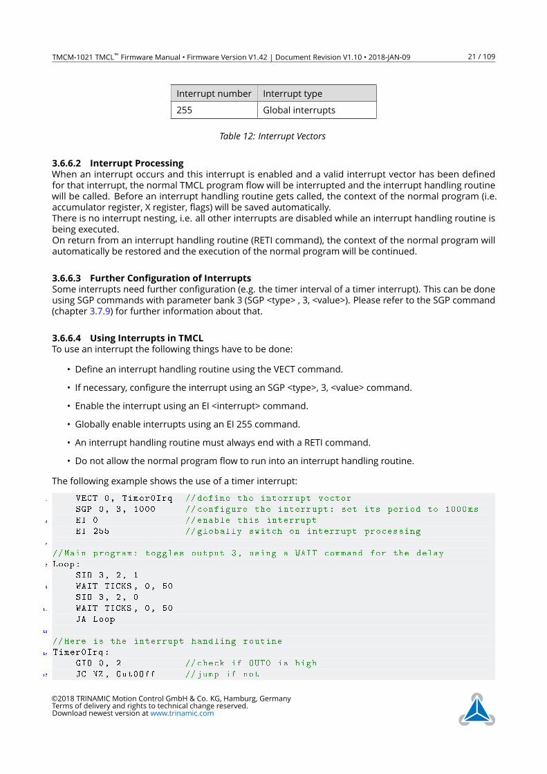
Interrupt number Interrupt type
255 Global interrupts
Table 12: Interrupt Vectors
3.6.6.2 Interrupt Processing
When an interrupt occurs and this interrupt is enabled and a valid interrupt vector has been defined
for that interrupt, the normal TMCL program flow will be interrupted and the interrupt handling routine
will be called. Before an interrupt handling routine gets called, the context of the normal program (i.e.
accumulator register, X register, flags) will be saved automatically.
There is no interrupt nesting, i.e. all other interrupts are disabled while an interrupt handling routine is
being executed.
On return from an interrupt handling routine (RETI command), the context of the normal program will
automatically be restored and the execution of the normal program will be continued.
3.6.6.3 Further Configuration of Interrupts
Some interrupts need further configuration (e.g. the timer interval of a timer interrupt). This can be done
using SGP commands with parameter bank 3 (SGP <type> , 3, <value>). Please refer to the SGP command
(chapter 3.7.9) for further information about that.
3.6.6.4 Using Interrupts in TMCL
To use an interrupt the following things have to be done:
• Define an interrupt handling routine using the VECT command.
• If necessary, configure the interrupt using an SGP <type>, 3, <value> command.
• Enable the interrupt using an EI <interrupt> command.
• Globally enable interrupts using an EI 255 command.
• An interrupt handling routine must always end with a RETI command.
• Do not allow the normal program flow to run into an interrupt handling routine.
The following example shows the use of a timer interrupt:
1 VECT 0, Timer0Irq // define the interrupt vector
SGP 0, 3, 1000 // configure the interrupt: set its period to 1000ms
3 EI 0 // enable this interrupt
EI 255 // globally switch on interrupt processing
5
//Main program: toggles output 3, using a WAIT command for the delay
7 Loop:
SIO 3, 2, 1
9 WAIT TICKS , 0, 50
SIO 3, 2, 0
11 WAIT TICKS , 0, 50
JA Loop
13
//Here is the interrupt handling routine
15 Timer0Irq:
GIO 0, 2 //check if OUT0 is high
17 JC NZ, Out0Off //jump if not
©2018 TRINAMIC Motion Control GmbH & Co. KG, Hamburg, Germany
Terms of delivery and rights to technical change reserved.
Download newest version at www.trinamic.com
TMCM-1021 TMCL™ Firmware Manual • Firmware Version V1.42 | Document Revision V1.10 • 2018-JAN-09 22 / 109
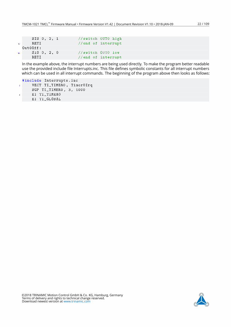
SIO 0, 2, 1 // switch OUT0 high
19 RETI //end of interrupt
Out0Off:
21 SIO 0, 2, 0 // switch OUT0 low
RETI //end of interrupt
In the example above, the interrupt numbers are being used directly. To make the program better readable
use the provided include file Interrupts.inc. This file defines symbolic constants for all interrupt numbers
which can be used in all interrupt commands. The beginning of the program above then looks as follows:
#include Interrupts.inc
2 VECT TI_TIMER0 , Timer0Irq
SGP TI_TIMER0 , 3, 1000
4 EI TI_TIMER0
EI TI_GLOBAL
©2018 TRINAMIC Motion Control GmbH & Co. KG, Hamburg, Germany
Terms of delivery and rights to technical change reserved.
Download newest version at www.trinamic.com
TMCM-1021 TMCL™ Firmware Manual • Firmware Version V1.42 | Document Revision V1.10 • 2018-JAN-09 23 / 109
3.7 Detailed TMCL Command Descriptions
The module specific commands are explained in more detail on the following pages. They are listed
according to their command number.
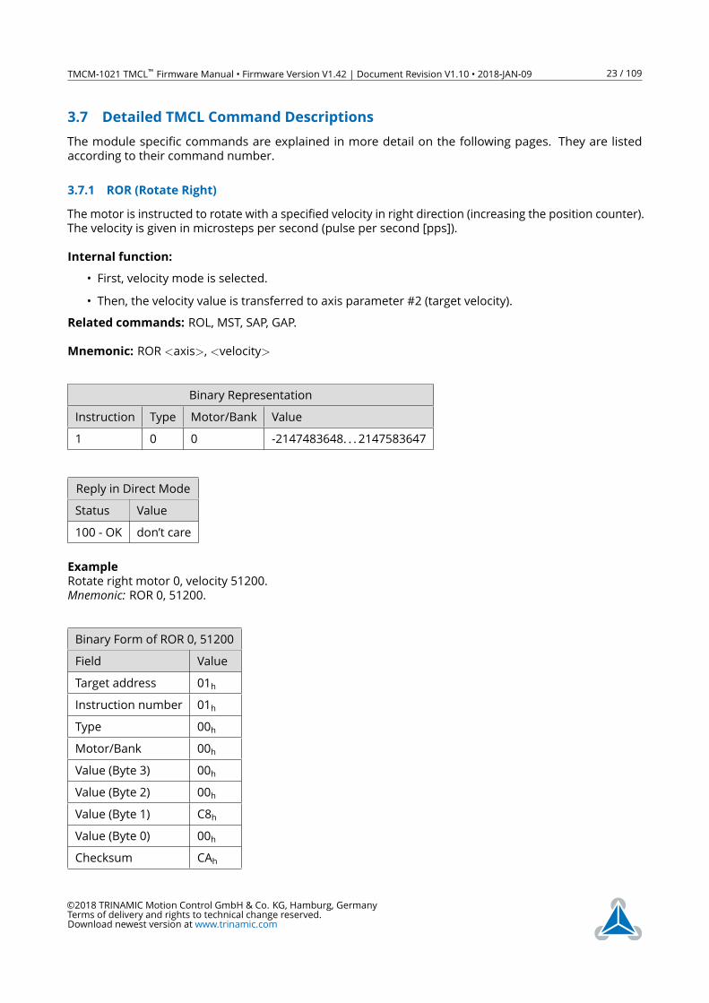
3.7.1 ROR (Rotate Right)
The motor is instructed to rotate with a specified velocity in right direction (increasing the position counter).
The velocity is given in microsteps per second (pulse per second [pps]).
Internal function:
• First, velocity mode is selected.
• Then, the velocity value is transferred to axis parameter #2 (target velocity).
Related commands: ROL, MST, SAP, GAP.
Mnemonic: ROR <axis>, <velocity>
Binary Representation
Instruction Type Motor/Bank Value
1 0 0 -2147483648. . . 2147583647
Reply in Direct Mode
Status Value
100 - OK don’t care
Example
Rotate right motor 0, velocity 51200.
Mnemonic: ROR 0, 51200.
Binary Form of ROR 0, 51200
Field Value
Target address 01h
Instruction number 01h
Type 00h
Motor/Bank 00h
Value (Byte 3) 00h
Value (Byte 2) 00h
Value (Byte 1) C8h
Value (Byte 0) 00h
Checksum CAh
©2018 TRINAMIC Motion Control GmbH & Co. KG, Hamburg, Germany
Terms of delivery and rights to technical change reserved.
Download newest version at www.trinamic.com
TMCM-1021 TMCL™ Firmware Manual • Firmware Version V1.42 | Document Revision V1.10 • 2018-JAN-09 24 / 109
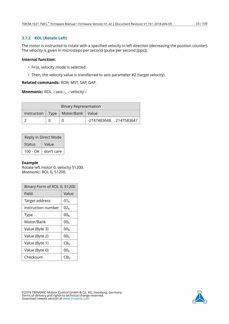
3.7.2 ROL (Rotate Left)
The motor is instructed to rotate with a specified velocity in left direction (decreasing the position counter).
The velocity is given in microsteps per second (pulse per second [pps]).
Internal function:
• First, velocity mode is selected.
• Then, the velocity value is transferred to axis parameter #2 (target velocity).
Related commands: ROR, MST, SAP, GAP.
Mnemonic: ROL <axis>, <velocity>
Binary Representation
Instruction Type Motor/Bank Value
2 0 0 -2147483648. . . 2147583647
Reply in Direct Mode
Status Value
100 - OK don’t care
Example
Rotate left motor 0, velocity 51200.
Mnemonic: ROL 0, 51200.
Binary Form of ROL 0, 51200
Field Value
Target address 01h
Instruction number 02h
Type 00h
Motor/Bank 00h
Value (Byte 3) 00h
Value (Byte 2) 00h
Value (Byte 1) C8h
Value (Byte 0) 00h
Checksum CBh
©2018 TRINAMIC Motion Control GmbH & Co. KG, Hamburg, Germany
Terms of delivery and rights to technical change reserved.
Download newest version at www.trinamic.com
TMCM-1021 TMCL™ Firmware Manual • Firmware Version V1.42 | Document Revision V1.10 • 2018-JAN-09 25 / 109
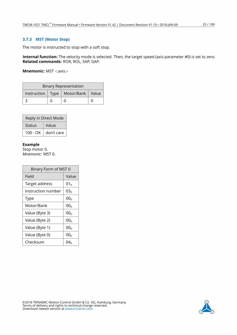
3.7.3 MST (Motor Stop)
The motor is instructed to stop with a soft stop.
Internal function: The velocity mode is selected. Then, the target speed (axis parameter #0) is set to zero.
Related commands: ROR, ROL, SAP, GAP.
Mnemonic: MST <axis>
Binary Representation
Instruction Type Motor/Bank Value
3 0 0 0
Reply in Direct Mode
Status Value
100 - OK don’t care
Example
Stop motor 0.
Mnemonic: MST 0.
Binary Form of MST 0
Field Value
Target address 01h
Instruction number 03h
Type 00h
Motor/Bank 00h
Value (Byte 3) 00h
Value (Byte 2) 00h
Value (Byte 1) 00h
Value (Byte 0) 00h
Checksum 04h
©2018 TRINAMIC Motion Control GmbH & Co. KG, Hamburg, Germany
Terms of delivery and rights to technical change reserved.
Download newest version at www.trinamic.com
TMCM-1021 TMCL™ Firmware Manual • Firmware Version V1.42 | Document Revision V1.10 • 2018-JAN-09 26 / 109
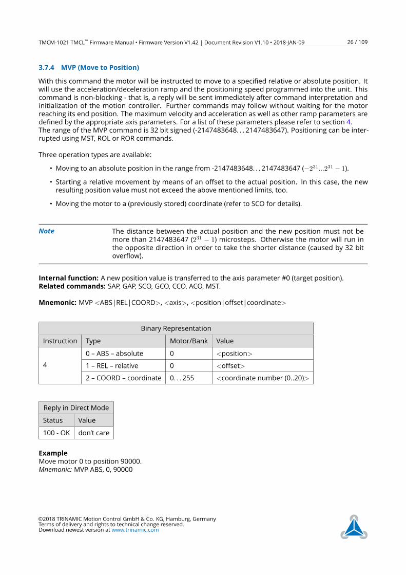
3.7.4 MVP (Move to Position)
With this command the motor will be instructed to move to a specified relative or absolute position. It
will use the acceleration/deceleration ramp and the positioning speed programmed into the unit. This
command is non-blocking - that is, a reply will be sent immediately after command interpretation and
initialization of the motion controller. Further commands may follow without waiting for the motor
reaching its end position. The maximum velocity and acceleration as well as other ramp parameters are
defined by the appropriate axis parameters. For a list of these parameters please refer to section 4.
The range of the MVP command is 32 bit signed (-2147483648. . . 2147483647). Positioning can be inter-
rupted using MST, ROL or ROR commands.
Three operation types are available:
• Moving to an absolute position in the range from -2147483648. . . 2147483647 (−231...231 − 1).
• Starting a relative movement by means of an offset to the actual position. In this case, the new
resulting position value must not exceed the above mentioned limits, too.
• Moving the motor to a (previously stored) coordinate (refer to SCO for details).
Note The distance between the actual position and the new position must not be
more than 2147483647 (231 − 1) microsteps. Otherwise the motor will run inthe opposite direction in order to take the shorter distance (caused by 32 bit
overflow).
Internal function: A new position value is transferred to the axis parameter #0 (target position).
Related commands: SAP, GAP, SCO, GCO, CCO, ACO, MST.
Mnemonic: MVP <ABS|REL|COORD>, <axis>, <position|offset|coordinate>
Binary Representation
Instruction Type Motor/Bank Value
4
0 – ABS – absolute 0 <position>
1 – REL – relative 0 <offset>
2 – COORD – coordinate 0. . . 255 <coordinate number (0..20)>
Reply in Direct Mode
Status Value
100 - OK don’t care
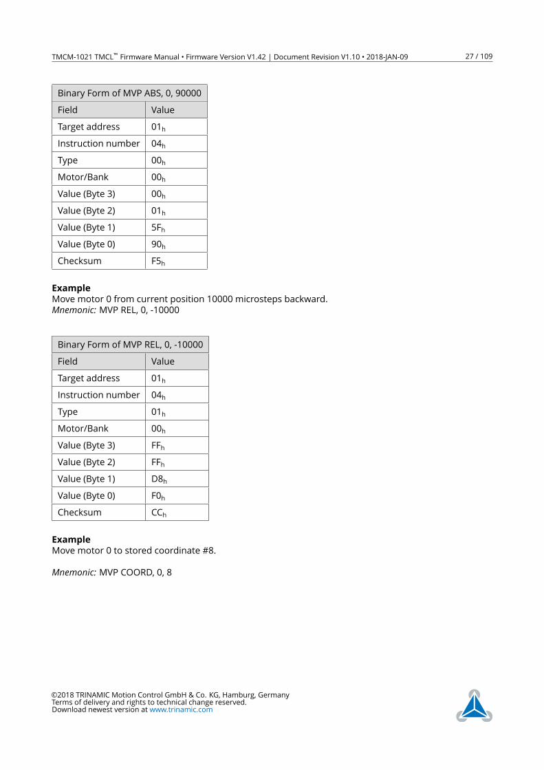
Example
Move motor 0 to position 90000.
Mnemonic: MVP ABS, 0, 90000
©2018 TRINAMIC Motion Control GmbH & Co. KG, Hamburg, Germany
Terms of delivery and rights to technical change reserved.
Download newest version at www.trinamic.com
TMCM-1021 TMCL™ Firmware Manual • Firmware Version V1.42 | Document Revision V1.10 • 2018-JAN-09 27 / 109
Binary Form of MVP ABS, 0, 90000
Field Value
Target address 01h
Instruction number 04h
Type 00h
Motor/Bank 00h
Value (Byte 3) 00h
Value (Byte 2) 01h
Value (Byte 1) 5Fh
Value (Byte 0) 90h
Checksum F5h
Example
Move motor 0 from current position 10000 microsteps backward.
Mnemonic: MVP REL, 0, -10000
Binary Form of MVP REL, 0, -10000
Field Value
Target address 01h
Instruction number 04h
Type 01h
Motor/Bank 00h
Value (Byte 3) FFh
Value (Byte 2) FFh
Value (Byte 1) D8h
Value (Byte 0) F0h
Checksum CCh
Example
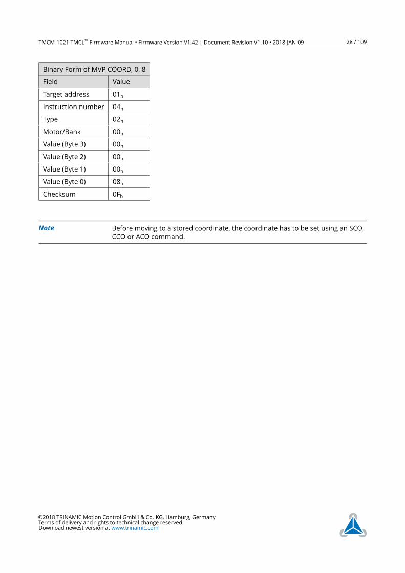
Move motor 0 to stored coordinate #8.
Mnemonic: MVP COORD, 0, 8
©2018 TRINAMIC Motion Control GmbH & Co. KG, Hamburg, Germany
Terms of delivery and rights to technical change reserved.
Download newest version at www.trinamic.com
TMCM-1021 TMCL™ Firmware Manual • Firmware Version V1.42 | Document Revision V1.10 • 2018-JAN-09 28 / 109
Binary Form of MVP COORD, 0, 8
Field Value
Target address 01h
Instruction number 04h
Type 02h
Motor/Bank 00h
Value (Byte 3) 00h
Value (Byte 2) 00h
Value (Byte 1) 00h
Value (Byte 0) 08h
Checksum 0Fh
Note Before moving to a stored coordinate, the coordinate has to be set using an SCO,
CCO or ACO command.
©2018 TRINAMIC Motion Control GmbH & Co. KG, Hamburg, Germany
Terms of delivery and rights to technical change reserved.
Download newest version at www.trinamic.com
TMCM-1021 TMCL™ Firmware Manual • Firmware Version V1.42 | Document Revision V1.10 • 2018-JAN-09 29 / 109
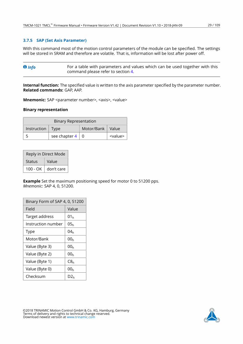
3.7.5 SAP (Set Axis Parameter)
With this command most of the motion control parameters of the module can be specified. The settings
will be stored in SRAM and therefore are volatile. That is, information will be lost after power off.
Info For a table with parameters and values which can be used together with this
command please refer to section 4.
Internal function: The specified value is written to the axis parameter specified by the parameter number.
Related commands: GAP, AAP.
Mnemonic: SAP <parameter number>, <axis>, <value>
Binary representation
Binary Representation
Instruction Type Motor/Bank Value
5 see chapter 4 0 <value>
Reply in Direct Mode
Status Value
100 - OK don’t care
Example Set the maximum positioning speed for motor 0 to 51200 pps.
Mnemonic: SAP 4, 0, 51200.
Binary Form of SAP 4, 0, 51200
Field Value
Target address 01h
Instruction number 05h
Type 04h
Motor/Bank 00h
Value (Byte 3) 00h
Value (Byte 2) 00h
Value (Byte 1) C8h
Value (Byte 0) 00h
Checksum D2h
©2018 TRINAMIC Motion Control GmbH & Co. KG, Hamburg, Germany
Terms of delivery and rights to technical change reserved.
Download newest version at www.trinamic.com
TMCM-1021 TMCL™ Firmware Manual • Firmware Version V1.42 | Document Revision V1.10 • 2018-JAN-09 30 / 109
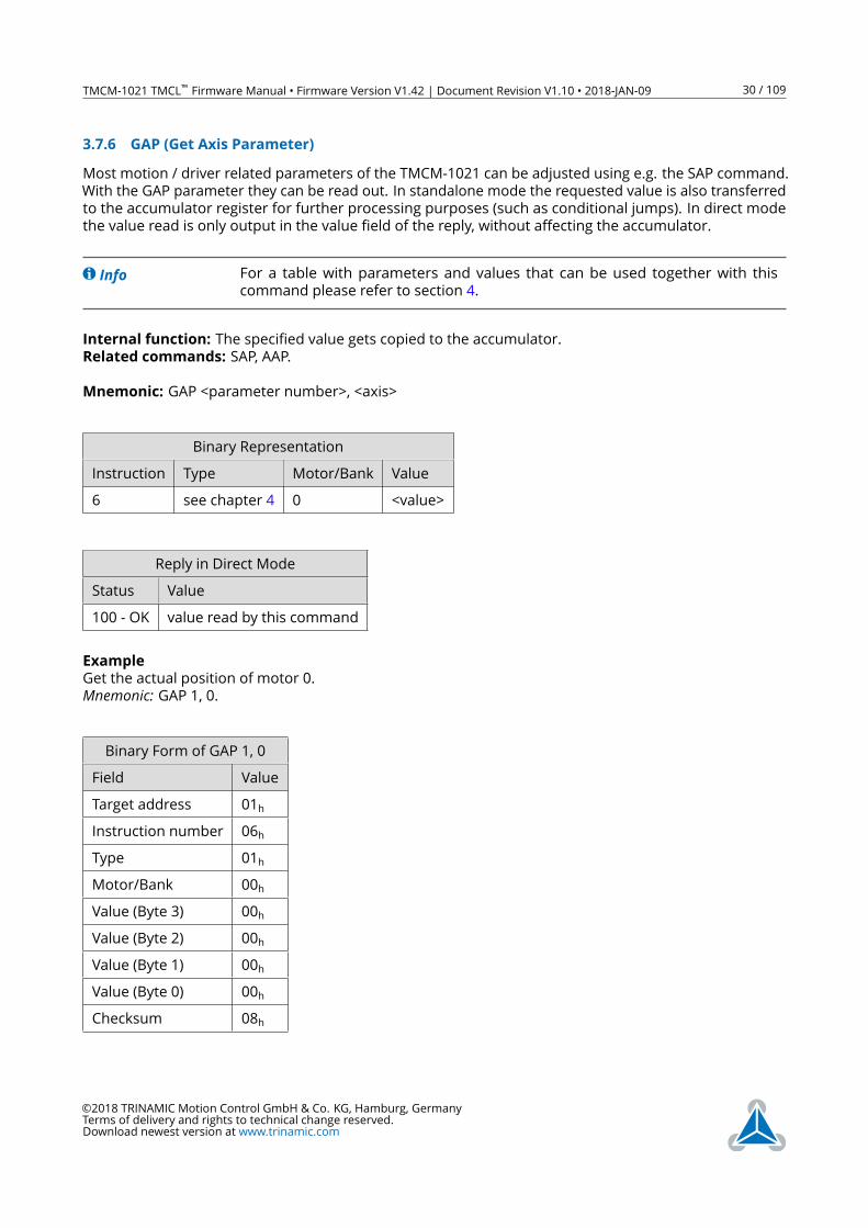
3.7.6 GAP (Get Axis Parameter)
Most motion / driver related parameters of the TMCM-1021 can be adjusted using e.g. the SAP command.
With the GAP parameter they can be read out. In standalone mode the requested value is also transferred
to the accumulator register for further processing purposes (such as conditional jumps). In direct mode
the value read is only output in the value field of the reply, without affecting the accumulator.
Info For a table with parameters and values that can be used together with this
command please refer to section 4.
Internal function: The specified value gets copied to the accumulator.
Related commands: SAP, AAP.
Mnemonic: GAP <parameter number>, <axis>
Binary Representation
Instruction Type Motor/Bank Value
6 see chapter 4 0 <value>
Reply in Direct Mode
Status Value
100 - OK value read by this command
Example
Get the actual position of motor 0.
Mnemonic: GAP 1, 0.
Binary Form of GAP 1, 0
Field Value
Target address 01h
Instruction number 06h
Type 01h
Motor/Bank 00h
Value (Byte 3) 00h
Value (Byte 2) 00h
Value (Byte 1) 00h
Value (Byte 0) 00h
Checksum 08h
©2018 TRINAMIC Motion Control GmbH & Co. KG, Hamburg, Germany
Terms of delivery and rights to technical change reserved.
Download newest version at www.trinamic.com
TMCM-1021 TMCL™ Firmware Manual • Firmware Version V1.42 | Document Revision V1.10 • 2018-JAN-09 31 / 109
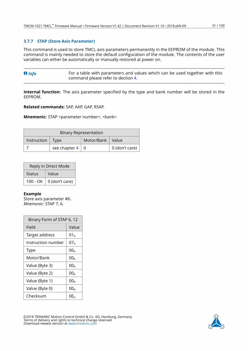
3.7.7 STAP (Store Axis Parameter)
This command is used to store TMCL axis parameters permanently in the EEPROM of the module. This
command is mainly needed to store the default configuration of the module. The contents of the user
variables can either be automatically or manually restored at power on.
Info For a table with parameters and values which can be used together with this
command please refer to dection 4.
Internal function: The axis parameter specified by the type and bank number will be stored in the
EEPROM.
Related commands: SAP, AAP, GAP, RSAP.
Mnemonic: STAP <parameter number>, <bank>
Binary Representation
Instruction Type Motor/Bank Value
7 see chapter 4 0 0 (don’t care)
Reply in Direct Mode
Status Value
100 - OK 0 (don’t care)
Example
Store axis parameter #6.
Mnemonic: STAP 7, 6.
Binary Form of STAP 6, 12
Field Value
Target address 01h
Instruction number 07h
Type 06h
Motor/Bank 00h
Value (Byte 3) 00h
Value (Byte 2) 00h
Value (Byte 1) 00h
Value (Byte 0) 00h
Checksum 0Eh
©2018 TRINAMIC Motion Control GmbH & Co. KG, Hamburg, Germany
Terms of delivery and rights to technical change reserved.
Download newest version at www.trinamic.com

TMCM-1021 TMCL™ Firmware Manual • Firmware Version V1.42 | Document Revision V1.10 • 2018-JAN-09 32 / 109
3.7.8 RSAP (Restore Axis Parameter)
With this command the contents of an axis parameter can be restored from the EEPROM. By default, all
axis parameters are automatically restored after power up. An axis parameter that has been changed
before can be reset to the stored value by this instruction.
Info For a table with parameters and values which can be used together with this
command please refer to section 4.
Internal function: The axis parameter specified by the type and bank number will be restored from the
EEPROM.
Related commands: SAP, AAP, GAP, RSAP.
Mnemonic: RSAP <parameter number>, <bank>
Binary Representation
Instruction Type Motor/Bank Value
8 see chapter 4 0 0 (don’t care)
Reply in Direct Mode
Status Value
100 - OK 0 (don’t care)
Example
Restore axis parameter #6.
Mnemonic: RSAP 8, 6.
Binary Form of RSAP 8, 6
Field Value
Target address 01h
Instruction number 08h
Type 06h
Motor/Bank 00h
Value (Byte 3) 00h
Value (Byte 2) 00h
Value (Byte 1) 00h
Value (Byte 0) 00h
Checksum 0Ah
©2018 TRINAMIC Motion Control GmbH & Co. KG, Hamburg, Germany
Terms of delivery and rights to technical change reserved.
Download newest version at www.trinamic.com
TMCM-1021 TMCL™ Firmware Manual • Firmware Version V1.42 | Document Revision V1.10 • 2018-JAN-09 33 / 109
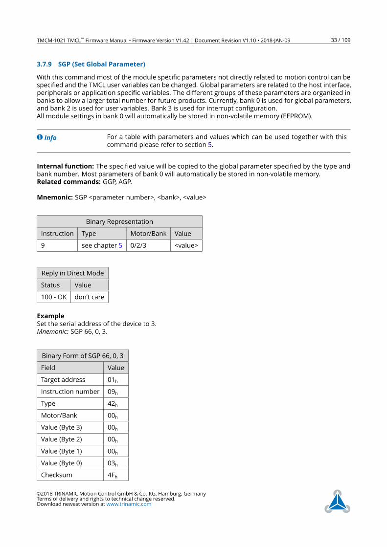
3.7.9 SGP (Set Global Parameter)
With this command most of the module specific parameters not directly related to motion control can be
specified and the TMCL user variables can be changed. Global parameters are related to the host interface,
peripherals or application specific variables. The different groups of these parameters are organized in
banks to allow a larger total number for future products. Currently, bank 0 is used for global parameters,
and bank 2 is used for user variables. Bank 3 is used for interrupt configuration.
All module settings in bank 0 will automatically be stored in non-volatile memory (EEPROM).
Info For a table with parameters and values which can be used together with this
command please refer to section 5.
Internal function: The specified value will be copied to the global parameter specified by the type and
bank number. Most parameters of bank 0 will automatically be stored in non-volatile memory.
Related commands: GGP, AGP.
Mnemonic: SGP <parameter number>, <bank>, <value>
Binary Representation
Instruction Type Motor/Bank Value
9 see chapter 5 0/2/3 <value>
Reply in Direct Mode
Status Value
100 - OK don’t care
Example
Set the serial address of the device to 3.
Mnemonic: SGP 66, 0, 3.
Binary Form of SGP 66, 0, 3
Field Value
Target address 01h
Instruction number 09h
Type 42h
Motor/Bank 00h
Value (Byte 3) 00h
Value (Byte 2) 00h
Value (Byte 1) 00h
Value (Byte 0) 03h
Checksum 4Fh
©2018 TRINAMIC Motion Control GmbH & Co. KG, Hamburg, Germany
Terms of delivery and rights to technical change reserved.
Download newest version at www.trinamic.com
TMCM-1021 TMCL™ Firmware Manual • Firmware Version V1.42 | Document Revision V1.10 • 2018-JAN-09 34 / 109
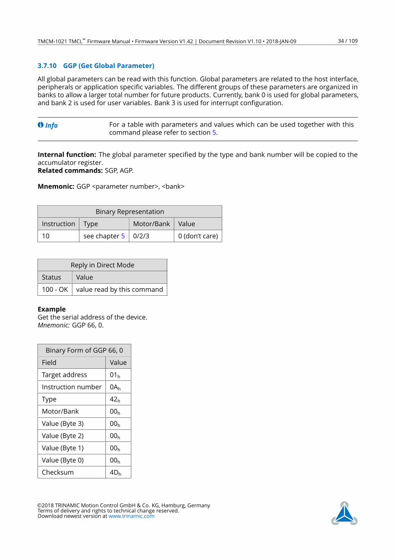
3.7.10 GGP (Get Global Parameter)
All global parameters can be read with this function. Global parameters are related to the host interface,
peripherals or application specific variables. The different groups of these parameters are organized in
banks to allow a larger total number for future products. Currently, bank 0 is used for global parameters,
and bank 2 is used for user variables. Bank 3 is used for interrupt configuration.
Info For a table with parameters and values which can be used together with this
command please refer to section 5.
Internal function: The global parameter specified by the type and bank number will be copied to the
accumulator register.
Related commands: SGP, AGP.
Mnemonic: GGP <parameter number>, <bank>
Binary Representation
Instruction Type Motor/Bank Value
10 see chapter 5 0/2/3 0 (don’t care)
Reply in Direct Mode
Status Value
100 - OK value read by this command
Example
Get the serial address of the device.
Mnemonic: GGP 66, 0.
Binary Form of GGP 66, 0
Field Value
Target address 01h
Instruction number 0Ah
Type 42h
Motor/Bank 00h
Value (Byte 3) 00h
Value (Byte 2) 00h
Value (Byte 1) 00h
Value (Byte 0) 00h
Checksum 4Dh
©2018 TRINAMIC Motion Control GmbH & Co. KG, Hamburg, Germany
Terms of delivery and rights to technical change reserved.
Download newest version at www.trinamic.com
TMCM-1021 TMCL™ Firmware Manual • Firmware Version V1.42 | Document Revision V1.10 • 2018-JAN-09 35 / 109
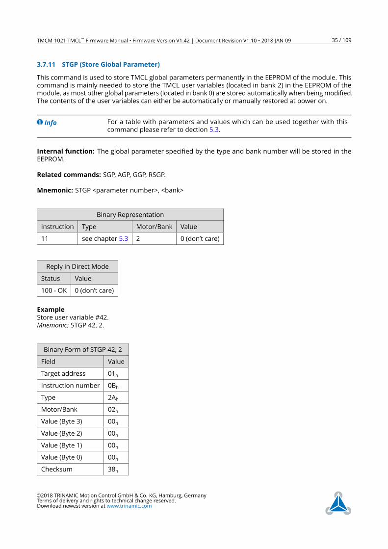
3.7.11 STGP (Store Global Parameter)
This command is used to store TMCL global parameters permanently in the EEPROM of the module. This
command is mainly needed to store the TMCL user variables (located in bank 2) in the EEPROM of the
module, as most other global parameters (located in bank 0) are stored automatically when being modified.
The contents of the user variables can either be automatically or manually restored at power on.
Info For a table with parameters and values which can be used together with this
command please refer to dection 5.3.
Internal function: The global parameter specified by the type and bank number will be stored in the
EEPROM.
Related commands: SGP, AGP, GGP, RSGP.
Mnemonic: STGP <parameter number>, <bank>
Binary Representation
Instruction Type Motor/Bank Value
11 see chapter 5.3 2 0 (don’t care)
Reply in Direct Mode
Status Value
100 - OK 0 (don’t care)
Example
Store user variable #42.
Mnemonic: STGP 42, 2.
Binary Form of STGP 42, 2
Field Value
Target address 01h
Instruction number 0Bh
Type 2Ah
Motor/Bank 02h
Value (Byte 3) 00h
Value (Byte 2) 00h
Value (Byte 1) 00h
Value (Byte 0) 00h
Checksum 38h
©2018 TRINAMIC Motion Control GmbH & Co. KG, Hamburg, Germany
Terms of delivery and rights to technical change reserved.
Download newest version at www.trinamic.com
TMCM-1021 TMCL™ Firmware Manual • Firmware Version V1.42 | Document Revision V1.10 • 2018-JAN-09 36 / 109
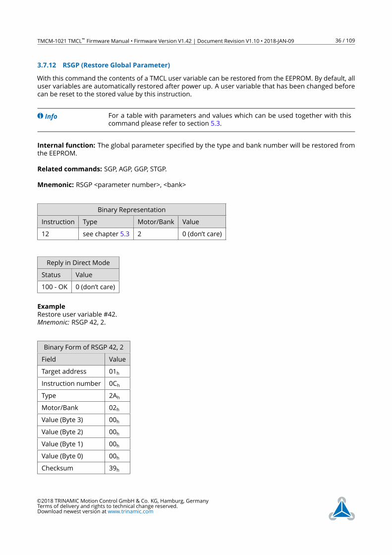
3.7.12 RSGP (Restore Global Parameter)
With this command the contents of a TMCL user variable can be restored from the EEPROM. By default, all
user variables are automatically restored after power up. A user variable that has been changed before
can be reset to the stored value by this instruction.
Info For a table with parameters and values which can be used together with this
command please refer to section 5.3.
Internal function: The global parameter specified by the type and bank number will be restored from
the EEPROM.
Related commands: SGP, AGP, GGP, STGP.
Mnemonic: RSGP <parameter number>, <bank>
Binary Representation
Instruction Type Motor/Bank Value
12 see chapter 5.3 2 0 (don’t care)
Reply in Direct Mode
Status Value
100 - OK 0 (don’t care)
Example
Restore user variable #42.
Mnemonic: RSGP 42, 2.
Binary Form of RSGP 42, 2
Field Value
Target address 01h
Instruction number 0Ch
Type 2Ah
Motor/Bank 02h
Value (Byte 3) 00h
Value (Byte 2) 00h
Value (Byte 1) 00h
Value (Byte 0) 00h
Checksum 39h
©2018 TRINAMIC Motion Control GmbH & Co. KG, Hamburg, Germany
Terms of delivery and rights to technical change reserved.
Download newest version at www.trinamic.com
TMCM-1021 TMCL™ Firmware Manual • Firmware Version V1.42 | Document Revision V1.10 • 2018-JAN-09 37 / 109
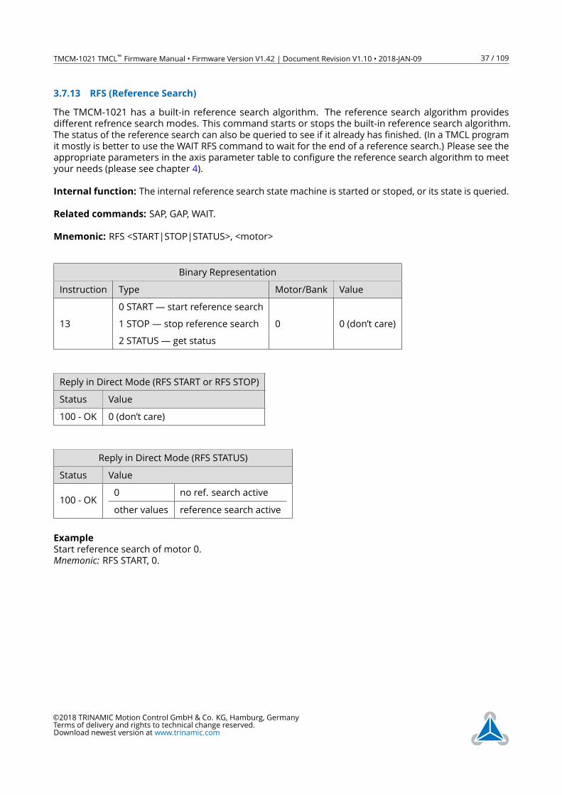
3.7.13 RFS (Reference Search)
The TMCM-1021 has a built-in reference search algorithm. The reference search algorithm provides
different refrence search modes. This command starts or stops the built-in reference search algorithm.
The status of the reference search can also be queried to see if it already has finished. (In a TMCL program
it mostly is better to use the WAIT RFS command to wait for the end of a reference search.) Please see the
appropriate parameters in the axis parameter table to configure the reference search algorithm to meet
your needs (please see chapter 4).
Internal function: The internal reference search state machine is started or stoped, or its state is queried.
Related commands: SAP, GAP, WAIT.
Mnemonic: RFS <START|STOP|STATUS>, <motor>
Binary Representation
Instruction Type Motor/Bank Value
0 START— start reference search
13 1 STOP— stop reference search 0 0 (don’t care)
2 STATUS— get status
Reply in Direct Mode (RFS START or RFS STOP)
Status Value
100 - OK 0 (don’t care)
Reply in Direct Mode (RFS STATUS)
Status Value
100 - OK0 no ref. search active
other values reference search active
Example
Start reference search of motor 0.
Mnemonic: RFS START, 0.
©2018 TRINAMIC Motion Control GmbH & Co. KG, Hamburg, Germany
Terms of delivery and rights to technical change reserved.
Download newest version at www.trinamic.com

TMCM-1021 TMCL™ Firmware Manual • Firmware Version V1.42 | Document Revision V1.10 • 2018-JAN-09 38 / 109
Binary Form of RFS START
Field Value
Target address 01h
Instruction number 0Dh
Type 00h
Motor/Bank 00h
Value (Byte 3) 00h
Value (Byte 2) 00h
Value (Byte 1) 00h
Value (Byte 0) 00h
Checksum 0Eh
©2018 TRINAMIC Motion Control GmbH & Co. KG, Hamburg, Germany
Terms of delivery and rights to technical change reserved.
Download newest version at www.trinamic.com
TMCM-1021 TMCL™ Firmware Manual • Firmware Version V1.42 | Document Revision V1.10 • 2018-JAN-09 39 / 109
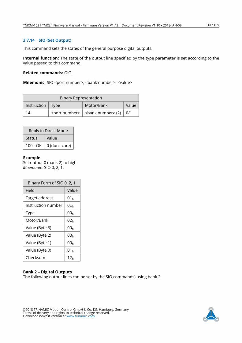
3.7.14 SIO (Set Output)
This command sets the states of the general purpose digital outputs.
Internal function: The state of the output line specified by the type parameter is set according to the
value passed to this command.
Related commands: GIO.
Mnemonic: SIO <port number>, <bank number>, <value>
Binary Representation
Instruction Type Motor/Bank Value
14 <port number> <bank number> (2) 0/1
Reply in Direct Mode
Status Value
100 - OK 0 (don’t care)
Example
Set output 0 (bank 2) to high.
Mnemonic: SIO 0, 2, 1.
Binary Form of SIO 0, 2, 1
Field Value
Target address 01h
Instruction number 0Eh
Type 00h
Motor/Bank 02h
Value (Byte 3) 00h
Value (Byte 2) 00h
Value (Byte 1) 00h
Value (Byte 0) 01h
Checksum 12h
Bank 2 – Digital Outputs
The following output lines can be set by the SIO commands) using bank 2.
©2018 TRINAMIC Motion Control GmbH & Co. KG, Hamburg, Germany
Terms of delivery and rights to technical change reserved.
Download newest version at www.trinamic.com
TMCM-1021 TMCL™ Firmware Manual • Firmware Version V1.42 | Document Revision V1.10 • 2018-JAN-09 40 / 109
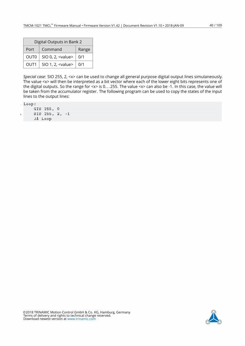
Digital Outputs in Bank 2
Port Command Range
OUT0 SIO 0, 2, <value> 0/1
OUT1 SIO 1, 2, <value> 0/1
Special case: SIO 255, 2, <x> can be used to change all general purpose digital output lines simulaneously.The value <x> will then be interpreted as a bit vector where each of the lower eight bits represents one of
the digital outputs. So the range for <x> is 0. . . 255. The value <x> can also be -1. In this case, the value will
be taken from the accumulator register. The following program can be used to copy the states of the input
lines to the output lines:
1 Loop:
GIO 255, 0
3 SIO 255, 2, -1
JA Loop
©2018 TRINAMIC Motion Control GmbH & Co. KG, Hamburg, Germany
Terms of delivery and rights to technical change reserved.
Download newest version at www.trinamic.com
TMCM-1021 TMCL™ Firmware Manual • Firmware Version V1.42 | Document Revision V1.10 • 2018-JAN-09 41 / 109
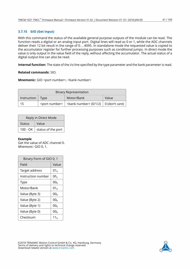
3.7.15 GIO (Get Input)
With this command the status of the available general purpose outputs of the module can be read. The
function reads a digital or an analog input port. Digital lines will read as 0 or 1, while the ADC channels
deliver their 12 bit result in the range of 0. . . 4095. In standalone mode the requested value is copied to
the accumulator register for further processing purposes such as conditional jumps. In direct mode the
value is only output in the value field of the reply, without affecting the accumulator. The actual status of a
digital output line can also be read.
Internal function: The state of the i/o line specified by the type parameter and the bank parameter is read.
Related commands: SIO.
Mnemonic: GIO <port number>, <bank number>
Binary Representation
Instruction Type Motor/Bank Value
15 <port number> <bank number> (0/1/2) 0 (don’t care)
Reply in Direct Mode
Status Value
100 - OK status of the port
Example
Get the value of ADC channel 0.
Mnemonic: GIO 0, 1.
Binary Form of GIO 0, 1
Field Value
Target address 01h
Instruction number 0Fh
Type 00h
Motor/Bank 01h
Value (Byte 3) 00h
Value (Byte 2) 00h
Value (Byte 1) 00h
Value (Byte 0) 00h
Checksum 11h
©2018 TRINAMIC Motion Control GmbH & Co. KG, Hamburg, Germany
Terms of delivery and rights to technical change reserved.
Download newest version at www.trinamic.com
TMCM-1021 TMCL™ Firmware Manual • Firmware Version V1.42 | Document Revision V1.10 • 2018-JAN-09 42 / 109
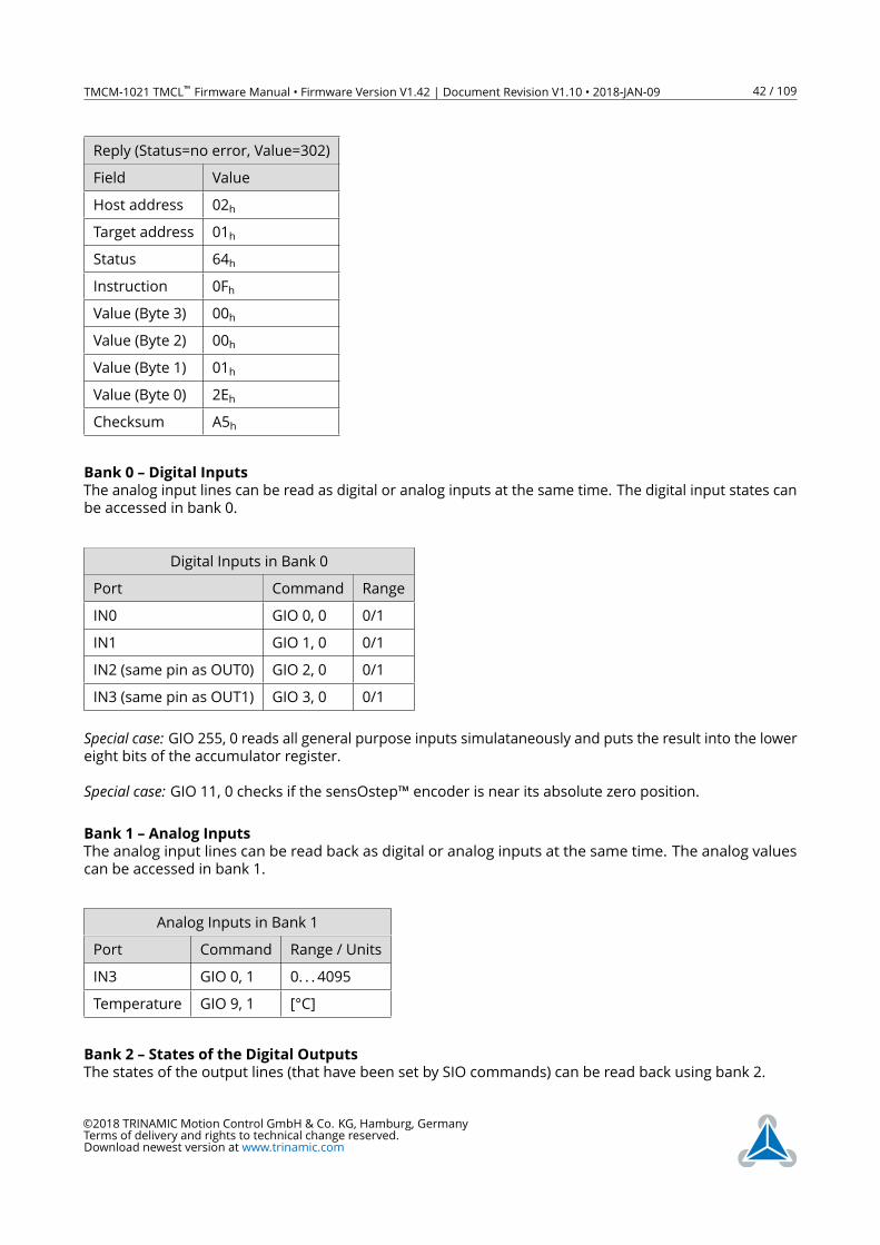
Reply (Status=no error, Value=302)
Field Value
Host address 02h
Target address 01h
Status 64h
Instruction 0Fh
Value (Byte 3) 00h
Value (Byte 2) 00h
Value (Byte 1) 01h
Value (Byte 0) 2Eh
Checksum A5h
Bank 0 – Digital Inputs
The analog input lines can be read as digital or analog inputs at the same time. The digital input states can
be accessed in bank 0.
Digital Inputs in Bank 0
Port Command Range
IN0 GIO 0, 0 0/1
IN1 GIO 1, 0 0/1
IN2 (same pin as OUT0) GIO 2, 0 0/1
IN3 (same pin as OUT1) GIO 3, 0 0/1
Special case: GIO 255, 0 reads all general purpose inputs simulataneously and puts the result into the lowereight bits of the accumulator register.
Special case: GIO 11, 0 checks if the sensOstep™ encoder is near its absolute zero position.
Bank 1 – Analog Inputs
The analog input lines can be read back as digital or analog inputs at the same time. The analog values
can be accessed in bank 1.
Analog Inputs in Bank 1
Port Command Range / Units
IN3 GIO 0, 1 0. . . 4095
Temperature GIO 9, 1 [°C]
Bank 2 – States of the Digital Outputs
The states of the output lines (that have been set by SIO commands) can be read back using bank 2.
©2018 TRINAMIC Motion Control GmbH & Co. KG, Hamburg, Germany
Terms of delivery and rights to technical change reserved.
Download newest version at www.trinamic.com
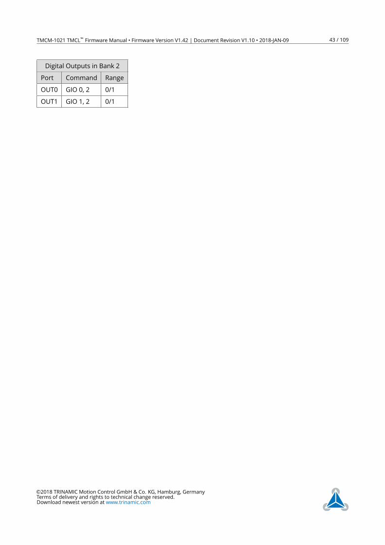
TMCM-1021 TMCL™ Firmware Manual • Firmware Version V1.42 | Document Revision V1.10 • 2018-JAN-09 43 / 109
Digital Outputs in Bank 2
Port Command Range
OUT0 GIO 0, 2 0/1
OUT1 GIO 1, 2 0/1
©2018 TRINAMIC Motion Control GmbH & Co. KG, Hamburg, Germany
Terms of delivery and rights to technical change reserved.
Download newest version at www.trinamic.com
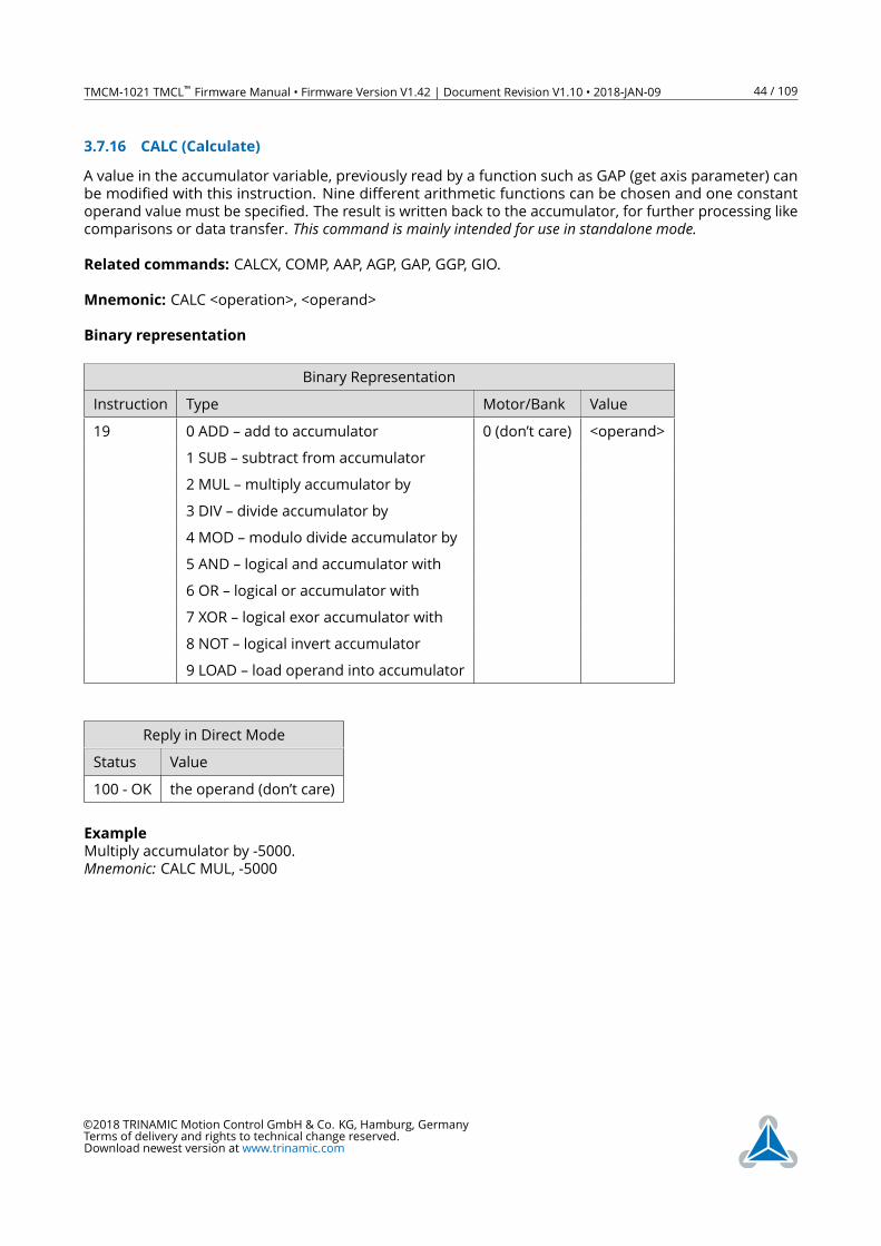
TMCM-1021 TMCL™ Firmware Manual • Firmware Version V1.42 | Document Revision V1.10 • 2018-JAN-09 44 / 109
3.7.16 CALC (Calculate)
A value in the accumulator variable, previously read by a function such as GAP (get axis parameter) can
be modified with this instruction. Nine different arithmetic functions can be chosen and one constant
operand value must be specified. The result is written back to the accumulator, for further processing like
comparisons or data transfer. This command is mainly intended for use in standalone mode.Related commands: CALCX, COMP, AAP, AGP, GAP, GGP, GIO.
Mnemonic: CALC <operation>, <operand>
Binary representation
Binary Representation
Instruction Type Motor/Bank Value
19 0 ADD – add to accumulator 0 (don’t care) <operand>
1 SUB – subtract from accumulator
2 MUL –multiply accumulator by
3 DIV – divide accumulator by
4 MOD –modulo divide accumulator by
5 AND – logical and accumulator with
6 OR – logical or accumulator with
7 XOR – logical exor accumulator with
8 NOT – logical invert accumulator
9 LOAD – load operand into accumulator
Reply in Direct Mode
Status Value
100 - OK the operand (don’t care)
Example
Multiply accumulator by -5000.
Mnemonic: CALC MUL, -5000
©2018 TRINAMIC Motion Control GmbH & Co. KG, Hamburg, Germany
Terms of delivery and rights to technical change reserved.
Download newest version at www.trinamic.com
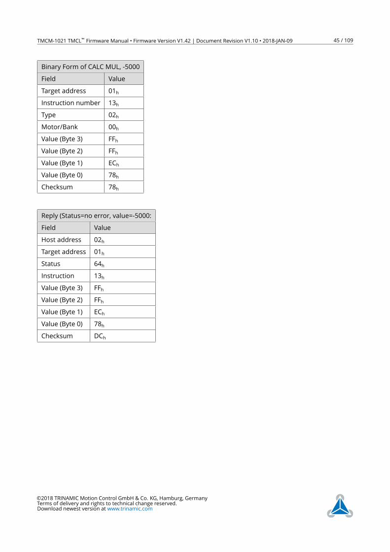
TMCM-1021 TMCL™ Firmware Manual • Firmware Version V1.42 | Document Revision V1.10 • 2018-JAN-09 45 / 109
Binary Form of CALC MUL, -5000
Field Value
Target address 01h
Instruction number 13h
Type 02h
Motor/Bank 00h
Value (Byte 3) FFh
Value (Byte 2) FFh
Value (Byte 1) ECh
Value (Byte 0) 78h
Checksum 78h
Reply (Status=no error, value=-5000:
Field Value
Host address 02h
Target address 01h
Status 64h
Instruction 13h
Value (Byte 3) FFh
Value (Byte 2) FFh
Value (Byte 1) ECh
Value (Byte 0) 78h
Checksum DCh
©2018 TRINAMIC Motion Control GmbH & Co. KG, Hamburg, Germany
Terms of delivery and rights to technical change reserved.
Download newest version at www.trinamic.com
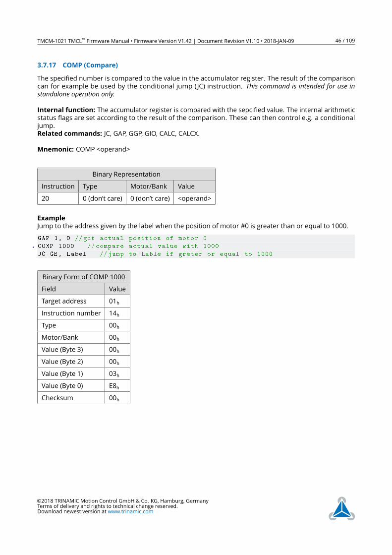
TMCM-1021 TMCL™ Firmware Manual • Firmware Version V1.42 | Document Revision V1.10 • 2018-JAN-09 46 / 109
3.7.17 COMP (Compare)
The specified number is compared to the value in the accumulator register. The result of the comparison
can for example be used by the conditional jump (JC) instruction. This command is intended for use instandalone operation only.Internal function: The accumulator register is compared with the sepcified value. The internal arithmetic
status flags are set according to the result of the comparison. These can then control e.g. a conditional
jump.
Related commands: JC, GAP, GGP, GIO, CALC, CALCX.
Mnemonic: COMP <operand>
Binary Representation
Instruction Type Motor/Bank Value
20 0 (don’t care) 0 (don’t care) <operand>
Example
Jump to the address given by the label when the position of motor #0 is greater than or equal to 1000.
GAP 1, 0 //get actual position of motor 0
2 COMP 1000 // compare actual value with 1000
JC GE, Label //jump to Lable if greter or equal to 1000
Binary Form of COMP 1000
Field Value
Target address 01h
Instruction number 14h
Type 00h
Motor/Bank 00h
Value (Byte 3) 00h
Value (Byte 2) 00h
Value (Byte 1) 03h
Value (Byte 0) E8h
Checksum 00h
©2018 TRINAMIC Motion Control GmbH & Co. KG, Hamburg, Germany
Terms of delivery and rights to technical change reserved.
Download newest version at www.trinamic.com
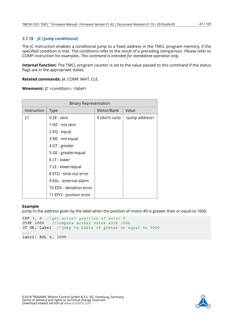
TMCM-1021 TMCL™ Firmware Manual • Firmware Version V1.42 | Document Revision V1.10 • 2018-JAN-09 47 / 109
3.7.18 JC (Jump conditional)
The JC instruction enables a conditional jump to a fixed address in the TMCL program memory, if the
specified condition is met. The conditions refer to the result of a preceding comparison. Please refer to
COMP instruction for examples. This command is intended for standalone operation only.Internal function: The TMCL program counter is set to the value passed to this command if the status
flags are in the appropriate states.
Related commands: JA, COMP, WAIT, CLE.
Mnemonic: JC <condition>, <label>
Binary Representation
Instruction Type Motor/Bank Value
21 0 ZE - zero 0 (don’t care) <jump address>
1 NZ - not zero
2 EQ - equal
3 NE - not equal
4 GT - greater
5 GE - greater/equal
6 LT - lower
7 LE - lower/equal
8 ETO - time out error
9 EAL - external alarm
10 EDV - deviation error
11 EPO - position error
Example
Jump to the address given by the label when the position of motor #0 is greater than or equal to 1000.
1 GAP 1, 0 //get actual position of motor 0
COMP 1000 // compare actual value with 1000
3 JC GE, Label //jump to Lable if greter or equal to 1000
...
5 Label: ROL 0, 1000
©2018 TRINAMIC Motion Control GmbH & Co. KG, Hamburg, Germany
Terms of delivery and rights to technical change reserved.
Download newest version at www.trinamic.com
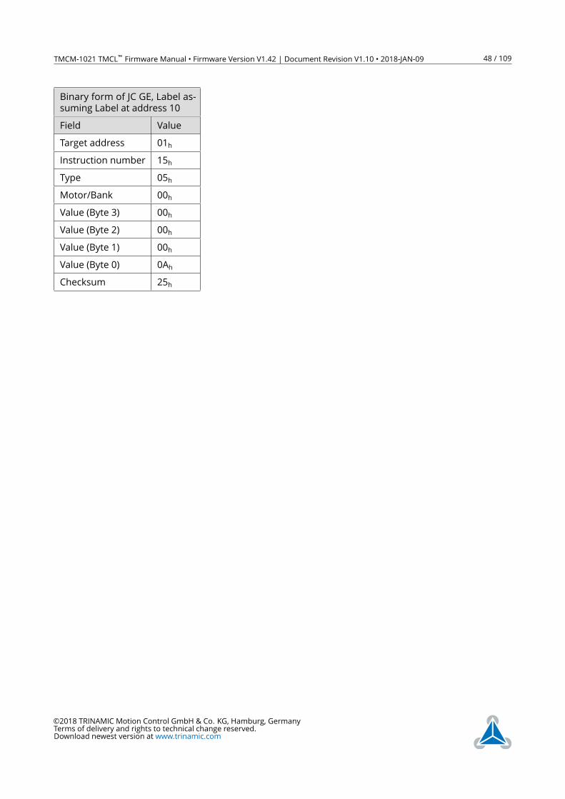
TMCM-1021 TMCL™ Firmware Manual • Firmware Version V1.42 | Document Revision V1.10 • 2018-JAN-09 48 / 109
Binary form of JC GE, Label as-
suming Label at address 10
Field Value
Target address 01h
Instruction number 15h
Type 05h
Motor/Bank 00h
Value (Byte 3) 00h
Value (Byte 2) 00h
Value (Byte 1) 00h
Value (Byte 0) 0Ah
Checksum 25h
©2018 TRINAMIC Motion Control GmbH & Co. KG, Hamburg, Germany
Terms of delivery and rights to technical change reserved.
Download newest version at www.trinamic.com

TMCM-1021 TMCL™ Firmware Manual • Firmware Version V1.42 | Document Revision V1.10 • 2018-JAN-09 49 / 109
3.7.19 JA (Jump always)
Jump to a fixed address in the TMCL program memory. This command is intended for standalone operationonly.Internal function: The TMCL program counter is set to the value passed to this command.
Related commands: JC, WAIT, CSUB.
Mnemonic: JA <label>
Binary Representation
Instruction Type Motor/Bank Value
22 0 (don’t care) 0 (don’t care) <jump address>
Example
An infinite loop in TMCL:
1 Loop:
MVP ABS , 0, 51200
3 WAIT POS , 0, 0
MVP ABS , 0, 0
5 WAIT POS , 0, 0
JA Loop
Binary form of the JA Loop command when the label Loop is at address 10:
Binary Form of JA Loop (assum-
ing Loop at address 10)
Field Value
Target address 01h
Instruction number 16h
Type 00h
Motor/Bank 00h
Value (Byte 3) 00h
Value (Byte 2) 00h
Value (Byte 1) 00h
Value (Byte 0) 0Ah
Checksum 21h
©2018 TRINAMIC Motion Control GmbH & Co. KG, Hamburg, Germany
Terms of delivery and rights to technical change reserved.
Download newest version at www.trinamic.com
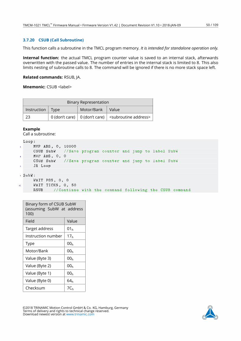
TMCM-1021 TMCL™ Firmware Manual • Firmware Version V1.42 | Document Revision V1.10 • 2018-JAN-09 50 / 109
3.7.20 CSUB (Call Subroutine)
This function calls a subroutine in the TMCL program memory. It is intended for standalone operation only.Internal function: the actual TMCL program counter value is saved to an internal stack, afterwards
overwritten with the passed value. The number of entries in the internal stack is limited to 8. This also
limits nesting of subroutine calls to 8. The command will be ignored if there is no more stack space left.
Related commands: RSUB, JA.
Mnemonic: CSUB <label>
Binary Representation
Instruction Type Motor/Bank Value
23 0 (don’t care) 0 (don’t care) <subroutine address>
Example
Call a subroutine:
Loop:
2 MVP ABS , 0, 10000
CSUB SubW //Save program counter and jump to label SubW
4 MVP ABS , 0, 0
CSUB SubW //Save program counter and jump to label SubW
6 JA Loop
8 SubW:
WAIT POS , 0, 0
10 WAIT TICKS , 0, 50
RSUB // Continue with the command following the CSUB command
Binary form of CSUB SubW
(assuming SubW at address
100)
Field Value
Target address 01h
Instruction number 17h
Type 00h
Motor/Bank 00h
Value (Byte 3) 00h
Value (Byte 2) 00h
Value (Byte 1) 00h
Value (Byte 0) 64h
Checksum 7Ch
©2018 TRINAMIC Motion Control GmbH & Co. KG, Hamburg, Germany
Terms of delivery and rights to technical change reserved.
Download newest version at www.trinamic.com
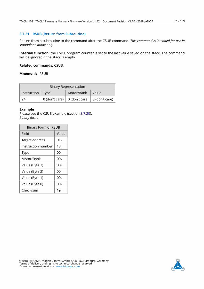
TMCM-1021 TMCL™ Firmware Manual • Firmware Version V1.42 | Document Revision V1.10 • 2018-JAN-09 51 / 109
3.7.21 RSUB (Return from Subroutine)
Return from a subroutine to the command after the CSUB command. This command is intended for use instandalone mode only.Internal function: the TMCL program counter is set to the last value saved on the stack. The command
will be ignored if the stack is empty.
Related commands: CSUB.
Mnemonic: RSUB
Binary Representation
Instruction Type Motor/Bank Value
24 0 (don’t care) 0 (don’t care) 0 (don’t care)
Example
Please see the CSUB example (section 3.7.20).
Binary form:
Binary Form of RSUB
Field Value
Target address 01h
Instruction number 18h
Type 00h
Motor/Bank 00h
Value (Byte 3) 00h
Value (Byte 2) 00h
Value (Byte 1) 00h
Value (Byte 0) 00h
Checksum 19h
©2018 TRINAMIC Motion Control GmbH & Co. KG, Hamburg, Germany
Terms of delivery and rights to technical change reserved.
Download newest version at www.trinamic.com
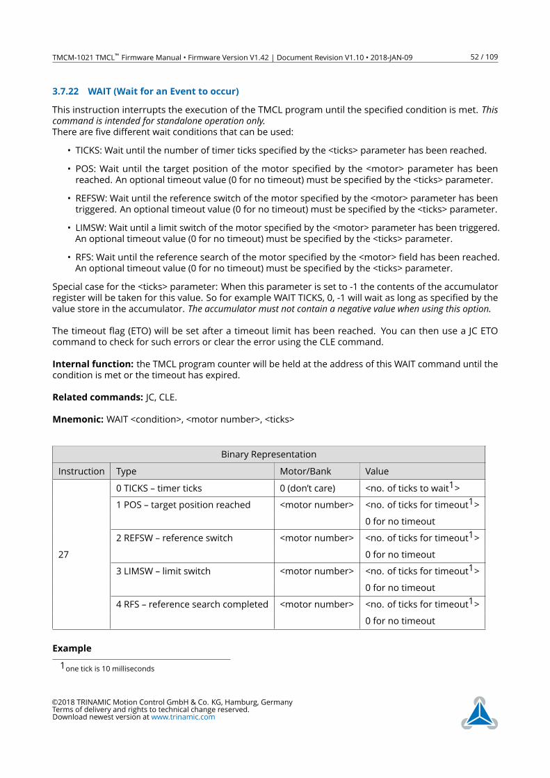
TMCM-1021 TMCL™ Firmware Manual • Firmware Version V1.42 | Document Revision V1.10 • 2018-JAN-09 52 / 109
3.7.22 WAIT (Wait for an Event to occur)
This instruction interrupts the execution of the TMCL program until the specified condition is met. Thiscommand is intended for standalone operation only.There are five different wait conditions that can be used:
• TICKS: Wait until the number of timer ticks specified by the <ticks> parameter has been reached.
• POS: Wait until the target position of the motor specified by the <motor> parameter has been
reached. An optional timeout value (0 for no timeout) must be specified by the <ticks> parameter.
• REFSW: Wait until the reference switch of the motor specified by the <motor> parameter has been
triggered. An optional timeout value (0 for no timeout) must be specified by the <ticks> parameter.
• LIMSW: Wait until a limit switch of the motor specified by the <motor> parameter has been triggered.
An optional timeout value (0 for no timeout) must be specified by the <ticks> parameter.
• RFS: Wait until the reference search of the motor specified by the <motor> field has been reached.
An optional timeout value (0 for no timeout) must be specified by the <ticks> parameter.
Special case for the <ticks> parameter: When this parameter is set to -1 the contents of the accumulator
register will be taken for this value. So for example WAIT TICKS, 0, -1 will wait as long as specified by the
value store in the accumulator. The accumulator must not contain a negative value when using this option.The timeout flag (ETO) will be set after a timeout limit has been reached. You can then use a JC ETO
command to check for such errors or clear the error using the CLE command.
Internal function: the TMCL program counter will be held at the address of this WAIT command until the
condition is met or the timeout has expired.
Related commands: JC, CLE.
Mnemonic: WAIT <condition>, <motor number>, <ticks>
Binary Representation
Instruction Type Motor/Bank Value
0 TICKS – timer ticks 0 (don’t care) <no. of ticks to wait1>
1 POS – target position reached <motor number> <no. of ticks for timeout1>
0 for no timeout
2 REFSW – reference switch <motor number> <no. of ticks for timeout1>
27 0 for no timeout
3 LIMSW – limit switch <motor number> <no. of ticks for timeout1>
0 for no timeout
4 RFS – reference search completed <motor number> <no. of ticks for timeout1>
0 for no timeout
Example
1one tick is 10 milliseconds
©2018 TRINAMIC Motion Control GmbH & Co. KG, Hamburg, Germany
Terms of delivery and rights to technical change reserved.
Download newest version at www.trinamic.com
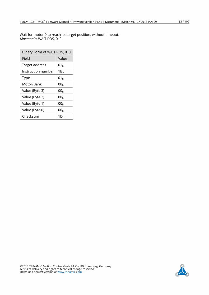
TMCM-1021 TMCL™ Firmware Manual • Firmware Version V1.42 | Document Revision V1.10 • 2018-JAN-09 53 / 109
Wait for motor 0 to reach its target position, without timeout.
Mnemonic: WAIT POS, 0, 0
Binary Form of WAIT POS, 0, 0
Field Value
Target address 01h
Instruction number 1Bh
Type 01h
Motor/Bank 00h
Value (Byte 3) 00h
Value (Byte 2) 00h
Value (Byte 1) 00h
Value (Byte 0) 00h
Checksum 1Dh
©2018 TRINAMIC Motion Control GmbH & Co. KG, Hamburg, Germany
Terms of delivery and rights to technical change reserved.
Download newest version at www.trinamic.com
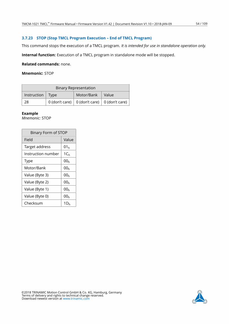
TMCM-1021 TMCL™ Firmware Manual • Firmware Version V1.42 | Document Revision V1.10 • 2018-JAN-09 54 / 109
3.7.23 STOP (Stop TMCL Program Execution – End of TMCL Program)
This command stops the execution of a TMCL program. It is intended for use in standalone operation only.Internal function: Execution of a TMCL program in standalone mode will be stopped.
Related commands: none.
Mnemonic: STOP
Binary Representation
Instruction Type Motor/Bank Value
28 0 (don’t care) 0 (don’t care) 0 (don’t care)
Example
Mnemonic: STOP
Binary Form of STOP
Field Value
Target address 01h
Instruction number 1Ch
Type 00h
Motor/Bank 00h
Value (Byte 3) 00h
Value (Byte 2) 00h
Value (Byte 1) 00h
Value (Byte 0) 00h
Checksum 1Dh
©2018 TRINAMIC Motion Control GmbH & Co. KG, Hamburg, Germany
Terms of delivery and rights to technical change reserved.
Download newest version at www.trinamic.com
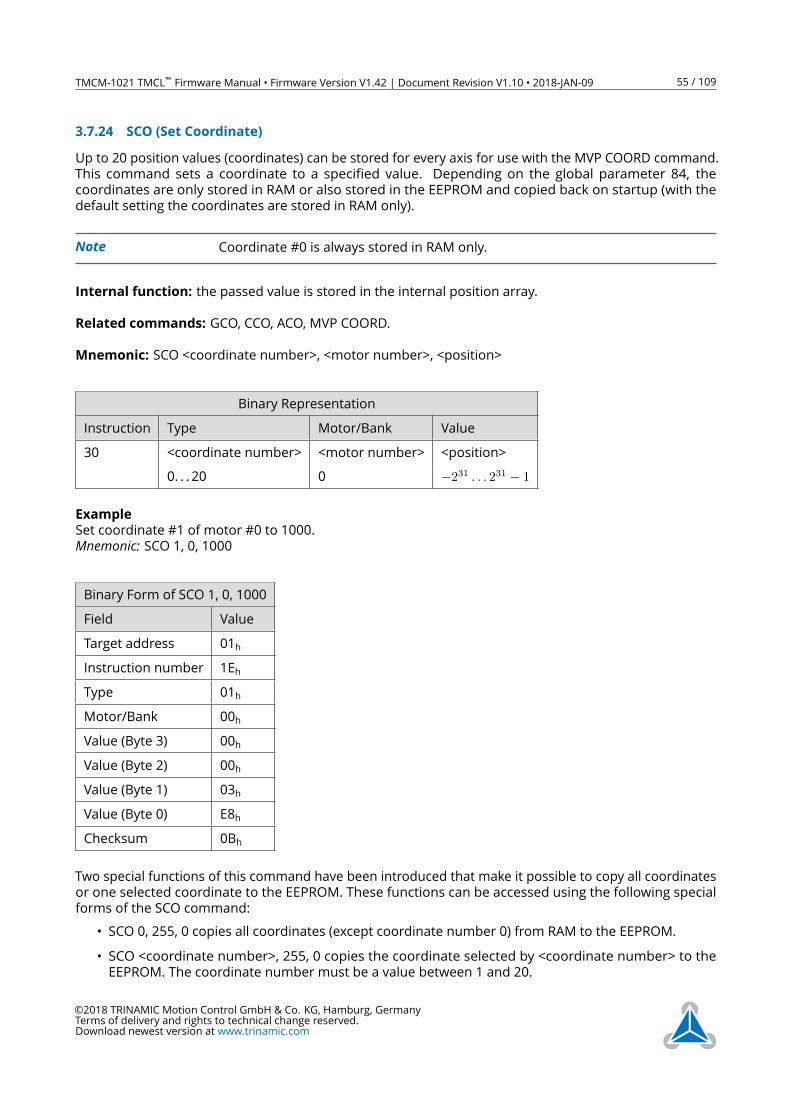
TMCM-1021 TMCL™ Firmware Manual • Firmware Version V1.42 | Document Revision V1.10 • 2018-JAN-09 55 / 109
3.7.24 SCO (Set Coordinate)
Up to 20 position values (coordinates) can be stored for every axis for use with the MVP COORD command.
This command sets a coordinate to a specified value. Depending on the global parameter 84, the
coordinates are only stored in RAM or also stored in the EEPROM and copied back on startup (with the
default setting the coordinates are stored in RAM only).
Note Coordinate #0 is always stored in RAM only.
Internal function: the passed value is stored in the internal position array.
Related commands: GCO, CCO, ACO, MVP COORD.
Mnemonic: SCO <coordinate number>, <motor number>, <position>
Binary Representation
Instruction Type Motor/Bank Value
30 <coordinate number> <motor number> <position>
0. . . 20 0 −231 . . . 231 − 1
Example
Set coordinate #1 of motor #0 to 1000.
Mnemonic: SCO 1, 0, 1000
Binary Form of SCO 1, 0, 1000
Field Value
Target address 01h
Instruction number 1Eh
Type 01h
Motor/Bank 00h
Value (Byte 3) 00h
Value (Byte 2) 00h
Value (Byte 1) 03h
Value (Byte 0) E8h
Checksum 0Bh
Two special functions of this command have been introduced that make it possible to copy all coordinates
or one selected coordinate to the EEPROM. These functions can be accessed using the following special
forms of the SCO command:
• SCO 0, 255, 0 copies all coordinates (except coordinate number 0) from RAM to the EEPROM.
• SCO <coordinate number>, 255, 0 copies the coordinate selected by <coordinate number> to the
EEPROM. The coordinate number must be a value between 1 and 20.
©2018 TRINAMIC Motion Control GmbH & Co. KG, Hamburg, Germany
Terms of delivery and rights to technical change reserved.
Download newest version at www.trinamic.com
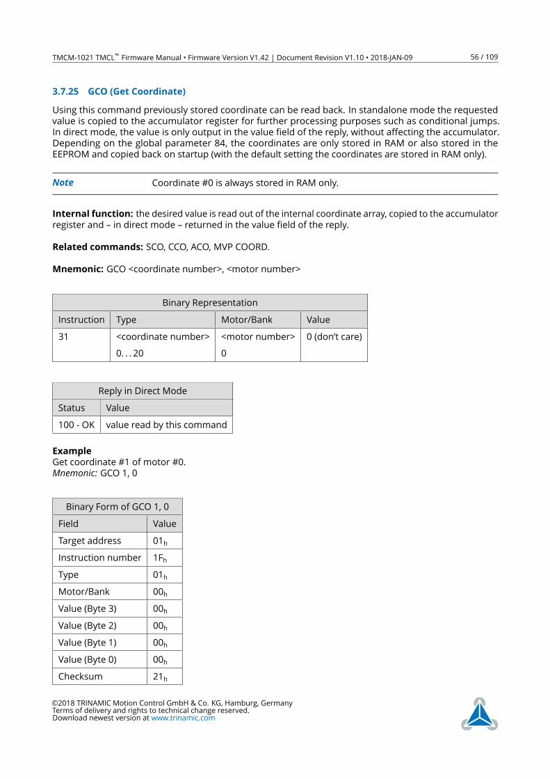
TMCM-1021 TMCL™ Firmware Manual • Firmware Version V1.42 | Document Revision V1.10 • 2018-JAN-09 56 / 109
3.7.25 GCO (Get Coordinate)
Using this command previously stored coordinate can be read back. In standalone mode the requested
value is copied to the accumulator register for further processing purposes such as conditional jumps.
In direct mode, the value is only output in the value field of the reply, without affecting the accumulator.
Depending on the global parameter 84, the coordinates are only stored in RAM or also stored in the
EEPROM and copied back on startup (with the default setting the coordinates are stored in RAM only).
Note Coordinate #0 is always stored in RAM only.
Internal function: the desired value is read out of the internal coordinate array, copied to the accumulator
register and – in direct mode – returned in the value field of the reply.
Related commands: SCO, CCO, ACO, MVP COORD.
Mnemonic: GCO <coordinate number>, <motor number>
Binary Representation
Instruction Type Motor/Bank Value
31 <coordinate number> <motor number> 0 (don’t care)
0. . . 20 0
Reply in Direct Mode
Status Value
100 - OK value read by this command
Example
Get coordinate #1 of motor #0.
Mnemonic: GCO 1, 0
Binary Form of GCO 1, 0
Field Value
Target address 01h
Instruction number 1Fh
Type 01h
Motor/Bank 00h
Value (Byte 3) 00h
Value (Byte 2) 00h
Value (Byte 1) 00h
Value (Byte 0) 00h
Checksum 21h
©2018 TRINAMIC Motion Control GmbH & Co. KG, Hamburg, Germany
Terms of delivery and rights to technical change reserved.
Download newest version at www.trinamic.com
TMCM-1021 TMCL™ Firmware Manual • Firmware Version V1.42 | Document Revision V1.10 • 2018-JAN-09 57 / 109
Two special functions of this command have been introduced that make it possible to copy all coordinates
or one selected coordinate from the EEPROM to the RAM.
These functions can be accessed using the following special forms of the GCO command:
• GCO 0, 255, 0 copies all coordinates (except coordinate number 0) from the EEPROM to the RAM.
• GCO <coordinate number>, 255, 0 copies the coordinate selected by <coordinate number> from the
EEPROM to the RAM. The coordinate number must be a value between 1 and 20.
©2018 TRINAMIC Motion Control GmbH & Co. KG, Hamburg, Germany
Terms of delivery and rights to technical change reserved.
Download newest version at www.trinamic.com
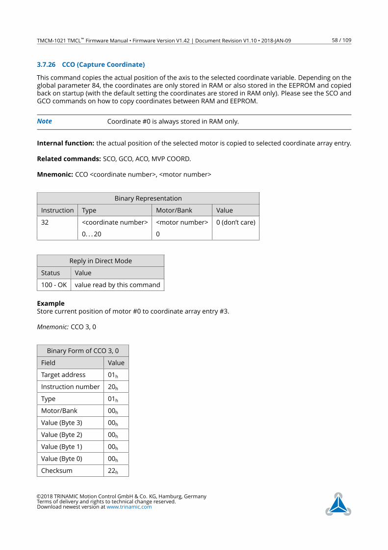
TMCM-1021 TMCL™ Firmware Manual • Firmware Version V1.42 | Document Revision V1.10 • 2018-JAN-09 58 / 109
3.7.26 CCO (Capture Coordinate)
This command copies the actual position of the axis to the selected coordinate variable. Depending on the
global parameter 84, the coordinates are only stored in RAM or also stored in the EEPROM and copied
back on startup (with the default setting the coordinates are stored in RAM only). Please see the SCO and
GCO commands on how to copy coordinates between RAM and EEPROM.
Note Coordinate #0 is always stored in RAM only.
Internal function: the actual position of the selected motor is copied to selected coordinate array entry.
Related commands: SCO, GCO, ACO, MVP COORD.
Mnemonic: CCO <coordinate number>, <motor number>
Binary Representation
Instruction Type Motor/Bank Value
32 <coordinate number> <motor number> 0 (don’t care)
0. . . 20 0
Reply in Direct Mode
Status Value
100 - OK value read by this command
Example
Store current position of motor #0 to coordinate array entry #3.
Mnemonic: CCO 3, 0
Binary Form of CCO 3, 0
Field Value
Target address 01h
Instruction number 20h
Type 01h
Motor/Bank 00h
Value (Byte 3) 00h
Value (Byte 2) 00h
Value (Byte 1) 00h
Value (Byte 0) 00h
Checksum 22h
©2018 TRINAMIC Motion Control GmbH & Co. KG, Hamburg, Germany
Terms of delivery and rights to technical change reserved.
Download newest version at www.trinamic.com
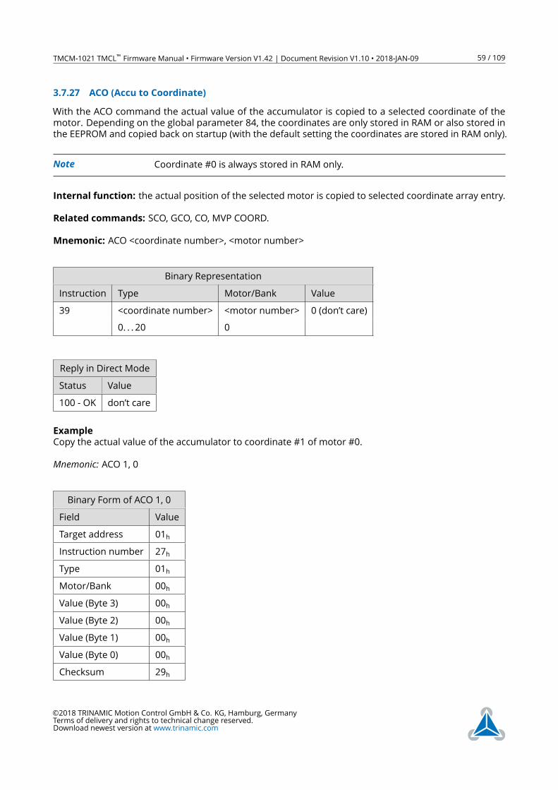
TMCM-1021 TMCL™ Firmware Manual • Firmware Version V1.42 | Document Revision V1.10 • 2018-JAN-09 59 / 109
3.7.27 ACO (Accu to Coordinate)
With the ACO command the actual value of the accumulator is copied to a selected coordinate of the
motor. Depending on the global parameter 84, the coordinates are only stored in RAM or also stored in
the EEPROM and copied back on startup (with the default setting the coordinates are stored in RAM only).
Note Coordinate #0 is always stored in RAM only.
Internal function: the actual position of the selected motor is copied to selected coordinate array entry.
Related commands: SCO, GCO, CO, MVP COORD.
Mnemonic: ACO <coordinate number>, <motor number>
Binary Representation
Instruction Type Motor/Bank Value
39 <coordinate number> <motor number> 0 (don’t care)
0. . . 20 0
Reply in Direct Mode
Status Value
100 - OK don’t care
Example
Copy the actual value of the accumulator to coordinate #1 of motor #0.
Mnemonic: ACO 1, 0
Binary Form of ACO 1, 0
Field Value
Target address 01h
Instruction number 27h
Type 01h
Motor/Bank 00h
Value (Byte 3) 00h
Value (Byte 2) 00h
Value (Byte 1) 00h
Value (Byte 0) 00h
Checksum 29h
©2018 TRINAMIC Motion Control GmbH & Co. KG, Hamburg, Germany
Terms of delivery and rights to technical change reserved.
Download newest version at www.trinamic.com
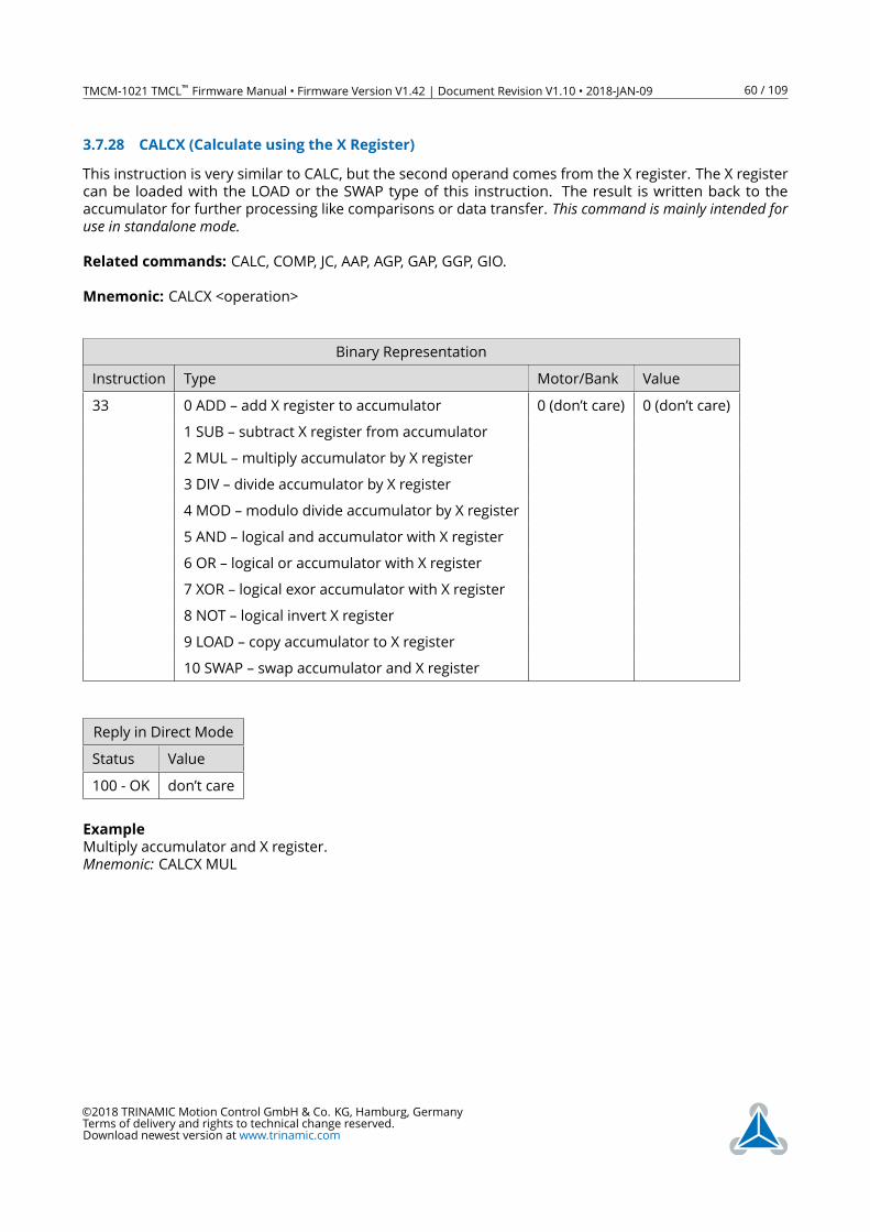
TMCM-1021 TMCL™ Firmware Manual • Firmware Version V1.42 | Document Revision V1.10 • 2018-JAN-09 60 / 109
3.7.28 CALCX (Calculate using the X Register)
This instruction is very similar to CALC, but the second operand comes from the X register. The X register
can be loaded with the LOAD or the SWAP type of this instruction. The result is written back to the
accumulator for further processing like comparisons or data transfer. This command is mainly intended foruse in standalone mode.Related commands: CALC, COMP, JC, AAP, AGP, GAP, GGP, GIO.
Mnemonic: CALCX <operation>
Binary Representation
Instruction Type Motor/Bank Value
33 0 ADD – add X register to accumulator 0 (don’t care) 0 (don’t care)
1 SUB – subtract X register from accumulator
2 MUL –multiply accumulator by X register
3 DIV – divide accumulator by X register
4 MOD –modulo divide accumulator by X register
5 AND – logical and accumulator with X register
6 OR – logical or accumulator with X register
7 XOR – logical exor accumulator with X register
8 NOT – logical invert X register
9 LOAD – copy accumulator to X register
10 SWAP – swap accumulator and X register
Reply in Direct Mode
Status Value
100 - OK don’t care
Example
Multiply accumulator and X register.
Mnemonic: CALCX MUL
©2018 TRINAMIC Motion Control GmbH & Co. KG, Hamburg, Germany
Terms of delivery and rights to technical change reserved.
Download newest version at www.trinamic.com
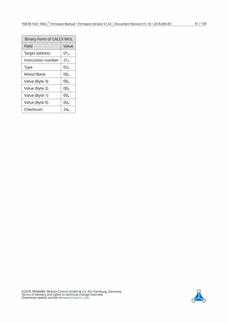
TMCM-1021 TMCL™ Firmware Manual • Firmware Version V1.42 | Document Revision V1.10 • 2018-JAN-09 61 / 109
Binary Form of CALCX MUL
Field Value
Target address 01h
Instruction number 21h
Type 02h
Motor/Bank 00h
Value (Byte 3) 00h
Value (Byte 2) 00h
Value (Byte 1) 00h
Value (Byte 0) 00h
Checksum 24h
©2018 TRINAMIC Motion Control GmbH & Co. KG, Hamburg, Germany
Terms of delivery and rights to technical change reserved.
Download newest version at www.trinamic.com
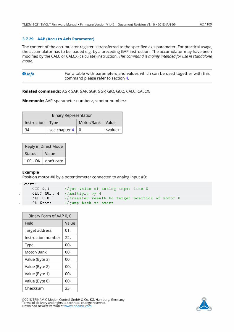
TMCM-1021 TMCL™ Firmware Manual • Firmware Version V1.42 | Document Revision V1.10 • 2018-JAN-09 62 / 109
3.7.29 AAP (Accu to Axis Parameter)
The content of the accumulator register is transferred to the specified axis parameter. For practical usage,
the accumulator has to be loaded e.g. by a preceding GAP instruction. The accumulator may have been
modified by the CALC or CALCX (calculate) instruction. This command is mainly intended for use in standalonemode.
Info For a table with parameters and values which can be used together with this
command please refer to section 4.
Related commands: AGP, SAP, GAP, SGP, GGP, GIO, GCO, CALC, CALCX.
Mnemonic: AAP <parameter number>, <motor number>
Binary Representation
Instruction Type Motor/Bank Value
34 see chapter 4 0 <value>
Reply in Direct Mode
Status Value
100 - OK don’t care
Example
Position motor #0 by a potentiometer connected to analog input #0:
1 Start:
GIO 0,1 //get value of analog input line 0
3 CALC MUL , 4 // multiply by 4
AAP 0,0 // transfer result to target position of motor 0
5 JA Start //jump back to start
Binary Form of AAP 0, 0
Field Value
Target address 01h
Instruction number 22h
Type 00h
Motor/Bank 00h
Value (Byte 3) 00h
Value (Byte 2) 00h
Value (Byte 1) 00h
Value (Byte 0) 00h
Checksum 23h
©2018 TRINAMIC Motion Control GmbH & Co. KG, Hamburg, Germany
Terms of delivery and rights to technical change reserved.
Download newest version at www.trinamic.com
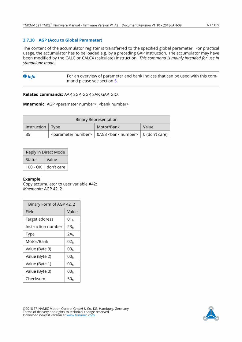
TMCM-1021 TMCL™ Firmware Manual • Firmware Version V1.42 | Document Revision V1.10 • 2018-JAN-09 63 / 109
3.7.30 AGP (Accu to Global Parameter)
The content of the accumulator register is transferred to the specified global parameter. For practical
usage, the accumulator has to be loaded e.g. by a preceding GAP instruction. The accumulator may have
been modified by the CALC or CALCX (calculate) instruction. This command is mainly intended for use instandalone mode.
Info For an overview of parameter and bank indices that can be used with this com-
mand please see section 5.
Related commands: AAP, SGP, GGP, SAP, GAP, GIO.
Mnemonic: AGP <parameter number>, <bank number>
Binary Representation
Instruction Type Motor/Bank Value
35 <parameter number> 0/2/3 <bank number> 0 (don’t care)
Reply in Direct Mode
Status Value
100 - OK don’t care
Example
Copy accumulator to user variable #42:
Mnemonic: AGP 42, 2
Binary Form of AGP 42, 2
Field Value
Target address 01h
Instruction number 23h
Type 2Ah
Motor/Bank 02h
Value (Byte 3) 00h
Value (Byte 2) 00h
Value (Byte 1) 00h
Value (Byte 0) 00h
Checksum 50h
©2018 TRINAMIC Motion Control GmbH & Co. KG, Hamburg, Germany
Terms of delivery and rights to technical change reserved.
Download newest version at www.trinamic.com
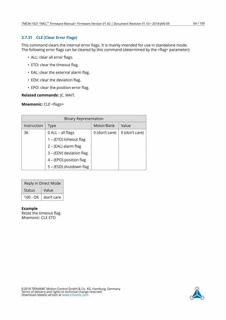
TMCM-1021 TMCL™ Firmware Manual • Firmware Version V1.42 | Document Revision V1.10 • 2018-JAN-09 64 / 109
3.7.31 CLE (Clear Error Flags)
This command clears the internal error flags. It is mainly intended for use in standalone mode.
The following error flags can be cleared by this command (determined by the <flag> parameter):
• ALL: clear all error flags.
• ETO: clear the timeout flag.
• EAL: clear the external alarm flag.
• EDV: clear the deviation flag.
• EPO: clear the position error flag.
Related commands: JC, WAIT.
Mnemonic: CLE <flags>
Binary Representation
Instruction Type Motor/Bank Value
36 0 ALL – all flags 0 (don’t care) 0 (don’t care)
1 – (ETO) timeout flag
2 – (EAL) alarm flag
3 – (EDV) deviation flag
4 – (EPO) position flag
5 – (ESD) shutdown flag
Reply in Direct Mode
Status Value
100 - OK don’t care
Example
Reset the timeout flag.
Mnemonic: CLE ETO
©2018 TRINAMIC Motion Control GmbH & Co. KG, Hamburg, Germany
Terms of delivery and rights to technical change reserved.
Download newest version at www.trinamic.com
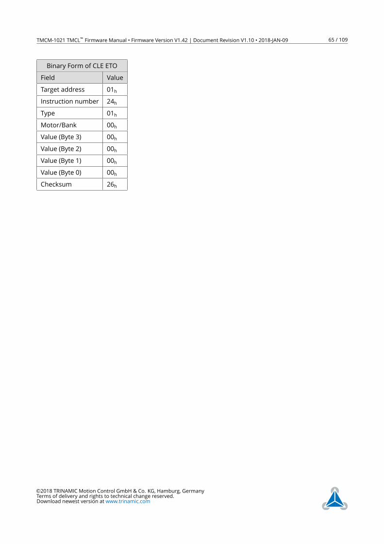
TMCM-1021 TMCL™ Firmware Manual • Firmware Version V1.42 | Document Revision V1.10 • 2018-JAN-09 65 / 109
Binary Form of CLE ETO
Field Value
Target address 01h
Instruction number 24h
Type 01h
Motor/Bank 00h
Value (Byte 3) 00h
Value (Byte 2) 00h
Value (Byte 1) 00h
Value (Byte 0) 00h
Checksum 26h
©2018 TRINAMIC Motion Control GmbH & Co. KG, Hamburg, Germany
Terms of delivery and rights to technical change reserved.
Download newest version at www.trinamic.com
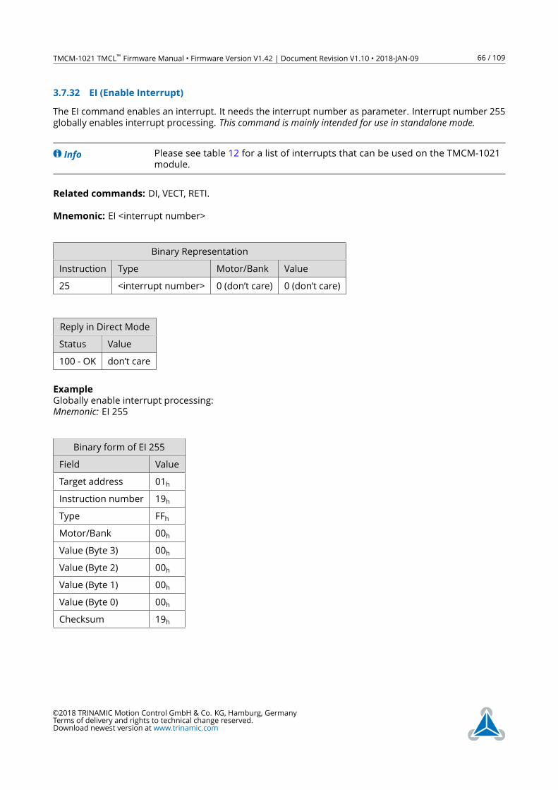
TMCM-1021 TMCL™ Firmware Manual • Firmware Version V1.42 | Document Revision V1.10 • 2018-JAN-09 66 / 109
3.7.32 EI (Enable Interrupt)
The EI command enables an interrupt. It needs the interrupt number as parameter. Interrupt number 255
globally enables interrupt processing. This command is mainly intended for use in standalone mode.
Info Please see table 12 for a list of interrupts that can be used on the TMCM-1021
module.
Related commands: DI, VECT, RETI.
Mnemonic: EI <interrupt number>
Binary Representation
Instruction Type Motor/Bank Value
25 <interrupt number> 0 (don’t care) 0 (don’t care)
Reply in Direct Mode
Status Value
100 - OK don’t care
Example
Globally enable interrupt processing:
Mnemonic: EI 255
Binary form of EI 255
Field Value
Target address 01h
Instruction number 19h
Type FFh
Motor/Bank 00h
Value (Byte 3) 00h
Value (Byte 2) 00h
Value (Byte 1) 00h
Value (Byte 0) 00h
Checksum 19h
©2018 TRINAMIC Motion Control GmbH & Co. KG, Hamburg, Germany
Terms of delivery and rights to technical change reserved.
Download newest version at www.trinamic.com
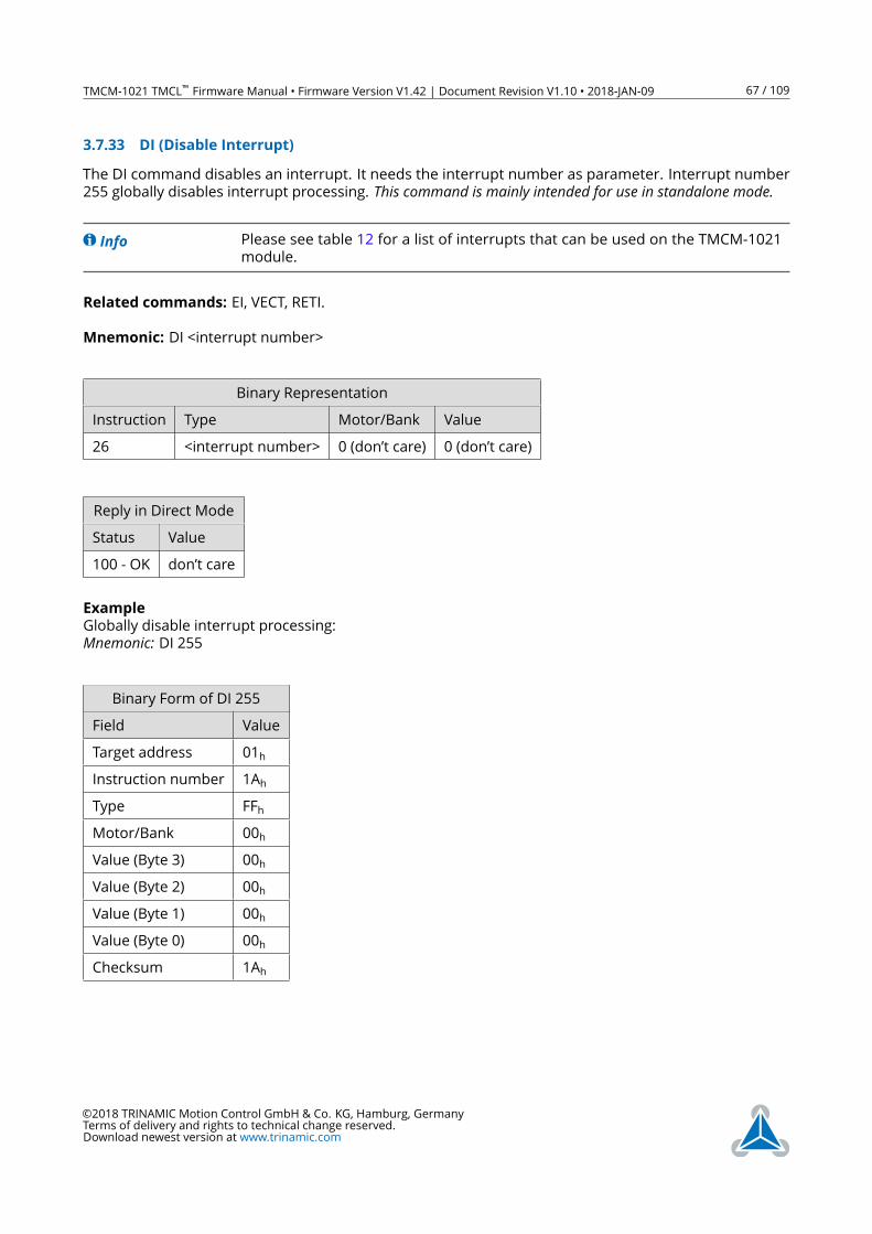
TMCM-1021 TMCL™ Firmware Manual • Firmware Version V1.42 | Document Revision V1.10 • 2018-JAN-09 67 / 109
3.7.33 DI (Disable Interrupt)
The DI command disables an interrupt. It needs the interrupt number as parameter. Interrupt number
255 globally disables interrupt processing. This command is mainly intended for use in standalone mode.
Info Please see table 12 for a list of interrupts that can be used on the TMCM-1021
module.
Related commands: EI, VECT, RETI.
Mnemonic: DI <interrupt number>
Binary Representation
Instruction Type Motor/Bank Value
26 <interrupt number> 0 (don’t care) 0 (don’t care)
Reply in Direct Mode
Status Value
100 - OK don’t care
Example
Globally disable interrupt processing:
Mnemonic: DI 255
Binary Form of DI 255
Field Value
Target address 01h
Instruction number 1Ah
Type FFh
Motor/Bank 00h
Value (Byte 3) 00h
Value (Byte 2) 00h
Value (Byte 1) 00h
Value (Byte 0) 00h
Checksum 1Ah
©2018 TRINAMIC Motion Control GmbH & Co. KG, Hamburg, Germany
Terms of delivery and rights to technical change reserved.
Download newest version at www.trinamic.com
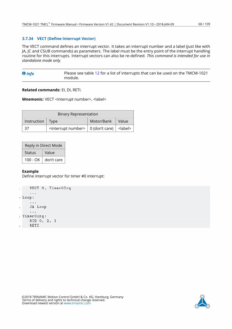
TMCM-1021 TMCL™ Firmware Manual • Firmware Version V1.42 | Document Revision V1.10 • 2018-JAN-09 68 / 109
3.7.34 VECT (Define Interrupt Vector)
The VECT command defines an interrupt vector. It takes an interrupt number and a label (just like with
JA, JC and CSUB commands) as parameters. The label must be the entry point of the interrupt handling
routine for this interrupts. Interrupt vectors can also be re-defined. This command is intended for use instandalone mode only.
Info Please see table 12 for a list of interrupts that can be used on the TMCM-1021
module.
Related commands: EI, DI, RETI.
Mnemonic: VECT <interrupt number>, <label>
Binary Representation
Instruction Type Motor/Bank Value
37 <interrupt number> 0 (don’t care) <label>
Reply in Direct Mode
Status Value
100 - OK don’t care
Example
Define interrupt vector for timer #0 interrupt:
1 VECT 0, Timer0Irq
...
3 Loop:
...
5 JA Loop
...
7 Timer0Irq:
SIO 0, 2, 1
9 RETI
©2018 TRINAMIC Motion Control GmbH & Co. KG, Hamburg, Germany
Terms of delivery and rights to technical change reserved.
Download newest version at www.trinamic.com

TMCM-1021 TMCL™ Firmware Manual • Firmware Version V1.42 | Document Revision V1.10 • 2018-JAN-09 69 / 109
Binary form of VECT (assuming
label is at 50)
Field Value
Target address 01h
Instruction number 25h
Type FFh
Motor/Bank 00h
Value (Byte 3) 00h
Value (Byte 2) 00h
Value (Byte 1) 00h
Value (Byte 0) 32h
Checksum 58h
©2018 TRINAMIC Motion Control GmbH & Co. KG, Hamburg, Germany
Terms of delivery and rights to technical change reserved.
Download newest version at www.trinamic.com
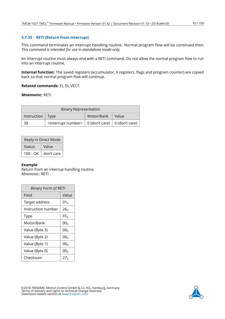
TMCM-1021 TMCL™ Firmware Manual • Firmware Version V1.42 | Document Revision V1.10 • 2018-JAN-09 70 / 109
3.7.35 RETI (Return from Interrupt)
This command terminates an interrupt handling routine. Normal program flow will be continued then.
This command is intended for use in standalone mode only.An interrupt routine must always end with a RETI command. Do not allow the normal program flow to run
into an interrupt routine.
Internal function: The saved registers (accumulator, X registers, flags and program counter) are copied
back so that normal program flow will continue.
Related commands: EI, DI, VECT.
Mnemonic: RETI
Binary Representation
Instruction Type Motor/Bank Value
38 <interrupt number> 0 (don’t care) 0 (don’t care)
Reply in Direct Mode
Status Value
100 - OK don’t care
Example
Return from an interrup handling routine.
Mnemonic: RETI
Binary Form of RETI
Field Value
Target address 01h
Instruction number 26h
Type FFh
Motor/Bank 00h
Value (Byte 3) 00h
Value (Byte 2) 00h
Value (Byte 1) 00h
Value (Byte 0) 00h
Checksum 27h
©2018 TRINAMIC Motion Control GmbH & Co. KG, Hamburg, Germany
Terms of delivery and rights to technical change reserved.
Download newest version at www.trinamic.com
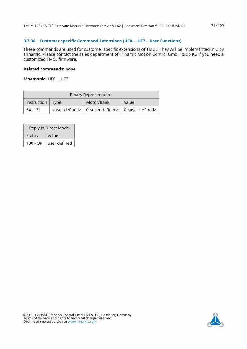
TMCM-1021 TMCL™ Firmware Manual • Firmware Version V1.42 | Document Revision V1.10 • 2018-JAN-09 71 / 109
3.7.36 Customer specific Command Extensions (UF0. . .UF7 – User Functions)
These commands are used for customer specific extensions of TMCL. They will be implemented in C by
Trinamic. Please contact the sales department of Trinamic Motion Control GmbH & Co KG if you need a
customized TMCL firmware.
Related commands: none.
Mnemonic: UF0. . .UF7
Binary Representation
Instruction Type Motor/Bank Value
64. . . 71 <user defined> 0 <user defined> 0 <user defined>
Reply in Direct Mode
Status Value
100 - OK user defined
©2018 TRINAMIC Motion Control GmbH & Co. KG, Hamburg, Germany
Terms of delivery and rights to technical change reserved.
Download newest version at www.trinamic.com
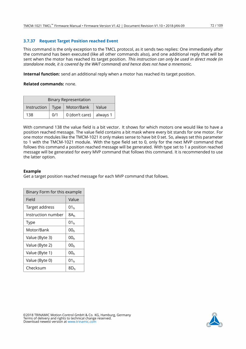
TMCM-1021 TMCL™ Firmware Manual • Firmware Version V1.42 | Document Revision V1.10 • 2018-JAN-09 72 / 109
3.7.37 Request Target Position reached Event
This command is the only exception to the TMCL protocol, as it sends two replies: One immediately after
the command has been executed (like all other commands also), and one additional reply that will be
sent when the motor has reached its target position. This instruction can only be used in direct mode (instandalone mode, it is covered by the WAIT command) and hence does not have a mnemonic.Internal function: send an additional reply when a motor has reached its target position.
Related commands: none.
Binary Representation
Instruction Type Motor/Bank Value
138 0/1 0 (don’t care) always 1
With command 138 the value field is a bit vector. It shows for which motors one would like to have a
position reached message. The value field contains a bit mask where every bit stands for one motor. For
one motor modules like the TMCM-1021 it only makes sense to have bit 0 set. So, always set this parameter
to 1 with the TMCM-1021 module. With the type field set to 0, only for the next MVP command that
follows this command a position reached message will be generated. With type set to 1 a position reached
message will be generated for every MVP command that follows this command. It is recommended to use
the latter option.
Example
Get a target position reached message for each MVP command that follows.
Binary Form for this example
Field Value
Target address 01h
Instruction number 8Ah
Type 01h
Motor/Bank 00h
Value (Byte 3) 00h
Value (Byte 2) 00h
Value (Byte 1) 00h
Value (Byte 0) 01h
Checksum 8Dh
©2018 TRINAMIC Motion Control GmbH & Co. KG, Hamburg, Germany
Terms of delivery and rights to technical change reserved.
Download newest version at www.trinamic.com
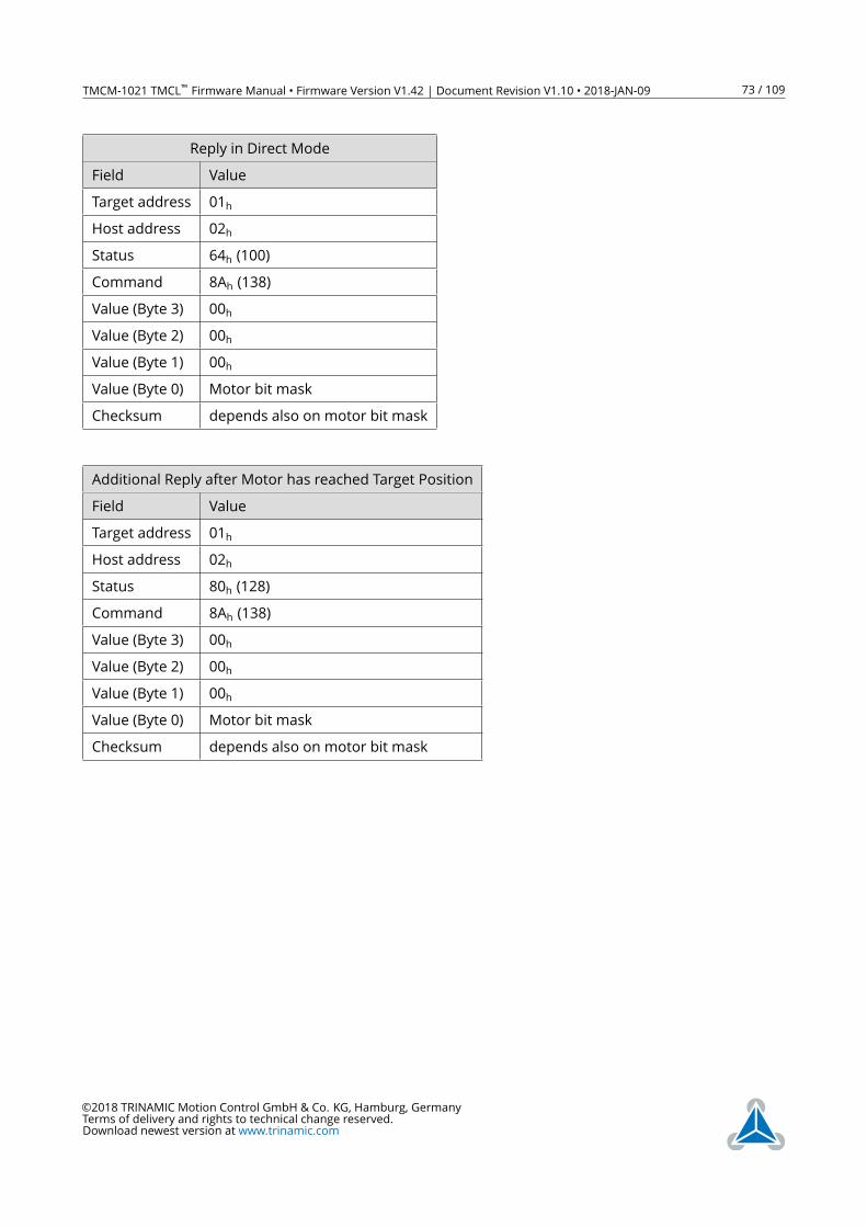
TMCM-1021 TMCL™ Firmware Manual • Firmware Version V1.42 | Document Revision V1.10 • 2018-JAN-09 73 / 109
Reply in Direct Mode
Field Value
Target address 01h
Host address 02h
Status 64h (100)
Command 8Ah (138)
Value (Byte 3) 00h
Value (Byte 2) 00h
Value (Byte 1) 00h
Value (Byte 0) Motor bit mask
Checksum depends also on motor bit mask
Additional Reply after Motor has reached Target Position
Field Value
Target address 01h
Host address 02h
Status 80h (128)
Command 8Ah (138)
Value (Byte 3) 00h
Value (Byte 2) 00h
Value (Byte 1) 00h
Value (Byte 0) Motor bit mask
Checksum depends also on motor bit mask
©2018 TRINAMIC Motion Control GmbH & Co. KG, Hamburg, Germany
Terms of delivery and rights to technical change reserved.
Download newest version at www.trinamic.com
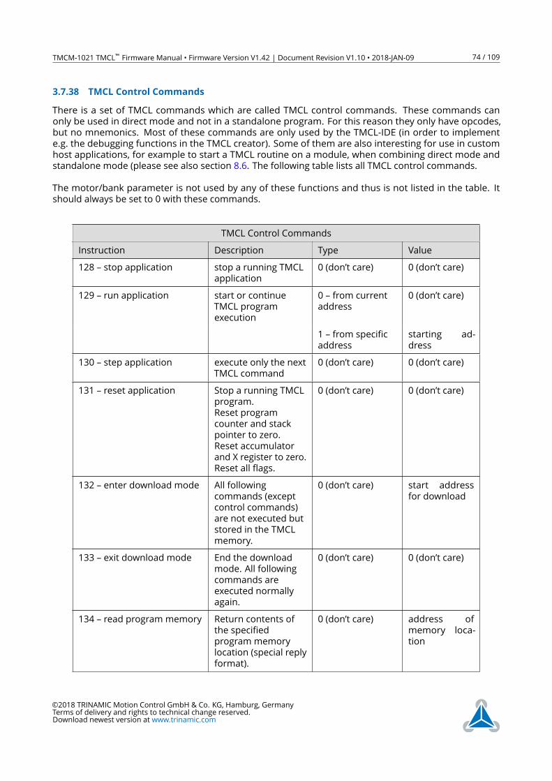
TMCM-1021 TMCL™ Firmware Manual • Firmware Version V1.42 | Document Revision V1.10 • 2018-JAN-09 74 / 109
3.7.38 TMCL Control Commands
There is a set of TMCL commands which are called TMCL control commands. These commands can
only be used in direct mode and not in a standalone program. For this reason they only have opcodes,
but no mnemonics. Most of these commands are only used by the TMCL-IDE (in order to implement
e.g. the debugging functions in the TMCL creator). Some of them are also interesting for use in custom
host applications, for example to start a TMCL routine on a module, when combining direct mode and
standalone mode (please see also section 8.6. The following table lists all TMCL control commands.
The motor/bank parameter is not used by any of these functions and thus is not listed in the table. It
should always be set to 0 with these commands.
TMCL Control Commands
Instruction Description Type Value
128 – stop application stop a running TMCL
application
0 (don’t care) 0 (don’t care)
129 – run application start or continue
TMCL program
execution
0 – from current
address
0 (don’t care)
1 – from specific
address
starting ad-
dress
130 – step application execute only the next
TMCL command
0 (don’t care) 0 (don’t care)
131 – reset application Stop a running TMCL
program.
Reset program
counter and stack
pointer to zero.
Reset accumulator
and X register to zero.
Reset all flags.
0 (don’t care) 0 (don’t care)
132 – enter download mode All following
commands (except
control commands)
are not executed but
stored in the TMCL
memory.
0 (don’t care) start address
for download
133 – exit download mode End the download
mode. All following
commands are
executed normally
again.
0 (don’t care) 0 (don’t care)
134 – read program memory Return contents of
the specified
program memory
location (special reply
format).
0 (don’t care) address of
memory loca-
tion
©2018 TRINAMIC Motion Control GmbH & Co. KG, Hamburg, Germany
Terms of delivery and rights to technical change reserved.
Download newest version at www.trinamic.com
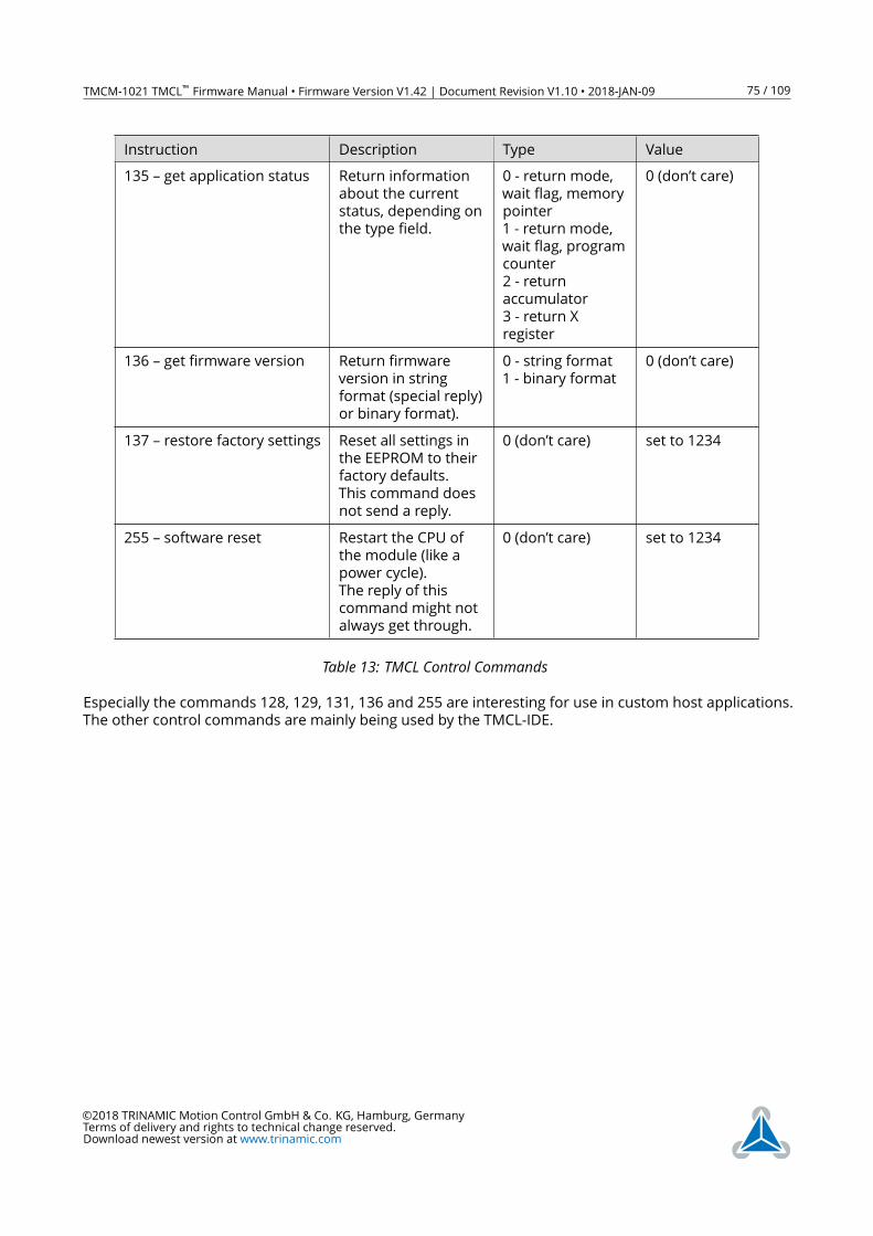
TMCM-1021 TMCL™ Firmware Manual • Firmware Version V1.42 | Document Revision V1.10 • 2018-JAN-09 75 / 109
Instruction Description Type Value
135 – get application status Return information
about the current
status, depending on
the type field.
0 - return mode,
wait flag, memory
pointer
1 - return mode,
wait flag, program
counter
2 - return
accumulator
3 - return X
register
0 (don’t care)
136 – get firmware version Return firmware
version in string
format (special reply)
or binary format).
0 - string format
1 - binary format
0 (don’t care)
137 – restore factory settings Reset all settings in
the EEPROM to their
factory defaults.
This command does
not send a reply.
0 (don’t care) set to 1234
255 – software reset Restart the CPU of
the module (like a
power cycle).
The reply of this
command might not
always get through.
0 (don’t care) set to 1234
Table 13: TMCL Control CommandsEspecially the commands 128, 129, 131, 136 and 255 are interesting for use in custom host applications.
The other control commands are mainly being used by the TMCL-IDE.
©2018 TRINAMIC Motion Control GmbH & Co. KG, Hamburg, Germany
Terms of delivery and rights to technical change reserved.
Download newest version at www.trinamic.com
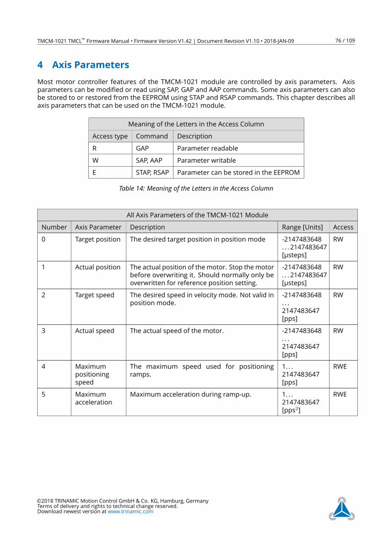
TMCM-1021 TMCL™ Firmware Manual • Firmware Version V1.42 | Document Revision V1.10 • 2018-JAN-09 76 / 109
4 Axis Parameters
Most motor controller features of the TMCM-1021 module are controlled by axis parameters. Axis
parameters can be modified or read using SAP, GAP and AAP commands. Some axis parameters can also
be stored to or restored from the EEPROM using STAP and RSAP commands. This chapter describes all
axis parameters that can be used on the TMCM-1021 module.
Meaning of the Letters in the Access Column
Access type Command Description
R GAP Parameter readable
W SAP, AAP Parameter writable
E STAP, RSAP Parameter can be stored in the EEPROM
Table 14: Meaning of the Letters in the Access Column
All Axis Parameters of the TMCM-1021 Module
Number Axis Parameter Description Range [Units] Access
0 Target position The desired target position in position mode -2147483648
. . . 2147483647
[µsteps]
RW
1 Actual position The actual position of the motor. Stop the motor
before overwriting it. Should normally only be
overwritten for reference position setting.
-2147483648
. . . 2147483647
[µsteps]
RW
2 Target speed The desired speed in velocity mode. Not valid in
position mode.
-2147483648
. . .
2147483647
[pps]
RW
3 Actual speed The actual speed of the motor. -2147483648
. . .
2147483647
[pps]
RW
4 Maximum
positioning
speed
The maximum speed used for positioning
ramps.
1. . .
2147483647
[pps]
RWE
5 Maximum
acceleration
Maximum acceleration during ramp-up. 1. . .
2147483647
[pps2]
RWE
©2018 TRINAMIC Motion Control GmbH & Co. KG, Hamburg, Germany
Terms of delivery and rights to technical change reserved.
Download newest version at www.trinamic.com
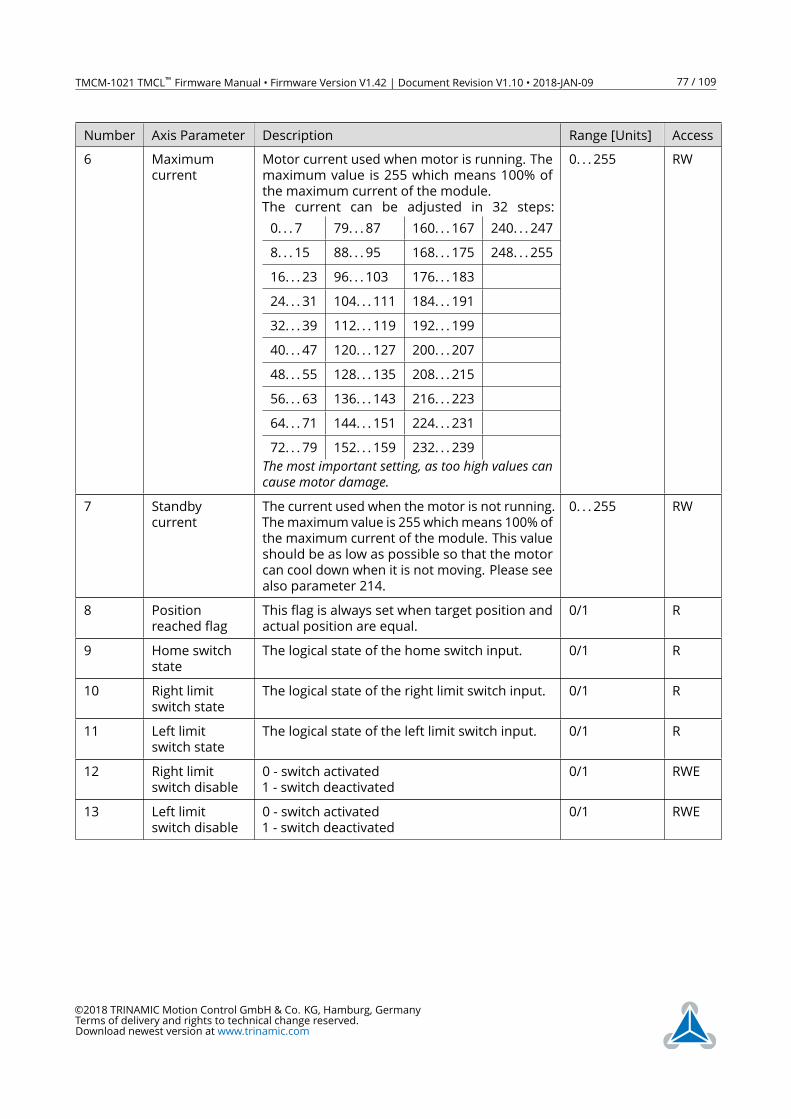
TMCM-1021 TMCL™ Firmware Manual • Firmware Version V1.42 | Document Revision V1.10 • 2018-JAN-09 77 / 109
Number Axis Parameter Description Range [Units] Access
6 Maximum
current
Motor current used when motor is running. The
maximum value is 255 which means 100% of
the maximum current of the module.
The current can be adjusted in 32 steps:
0. . . 7 79. . . 87 160. . . 167 240. . . 247
8. . . 15 88. . . 95 168. . . 175 248. . . 255
16. . . 23 96. . . 103 176. . . 183
24. . . 31 104. . . 111 184. . . 191
32. . . 39 112. . . 119 192. . . 199
40. . . 47 120. . . 127 200. . . 207
48. . . 55 128. . . 135 208. . . 215
56. . . 63 136. . . 143 216. . . 223
64. . . 71 144. . . 151 224. . . 231
72. . . 79 152. . . 159 232. . . 239
The most important setting, as too high values cancause motor damage.
0. . . 255 RW
7 Standby
current
The current used when the motor is not running.
Themaximum value is 255 whichmeans 100% of
the maximum current of the module. This value
should be as low as possible so that the motor
can cool down when it is not moving. Please see
also parameter 214.
0. . . 255 RW
8 Position
reached flag
This flag is always set when target position and
actual position are equal.
0/1 R
9 Home switch
state
The logical state of the home switch input. 0/1 R
10 Right limit
switch state
The logical state of the right limit switch input. 0/1 R
11 Left limit
switch state
The logical state of the left limit switch input. 0/1 R
12 Right limit
switch disable
0 - switch activated
1 - switch deactivated
0/1 RWE
13 Left limit
switch disable
0 - switch activated
1 - switch deactivated
0/1 RWE
©2018 TRINAMIC Motion Control GmbH & Co. KG, Hamburg, Germany
Terms of delivery and rights to technical change reserved.
Download newest version at www.trinamic.com
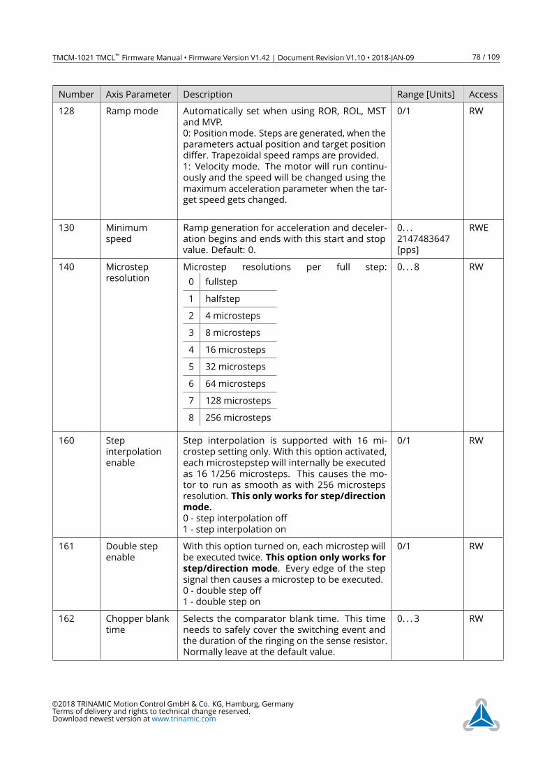
TMCM-1021 TMCL™ Firmware Manual • Firmware Version V1.42 | Document Revision V1.10 • 2018-JAN-09 78 / 109
Number Axis Parameter Description Range [Units] Access
128 Ramp mode Automatically set when using ROR, ROL, MST
and MVP.
0: Positionmode. Steps are generated, when the
parameters actual position and target position
differ. Trapezoidal speed ramps are provided.
1: Velocity mode. The motor will run continu-
ously and the speed will be changed using the
maximum acceleration parameter when the tar-
get speed gets changed.
0/1 RW
130 Minimum
speed
Ramp generation for acceleration and deceler-
ation begins and ends with this start and stop
value. Default: 0.
0. . .
2147483647
[pps]
RWE
140 Microstep
resolution
Microstep resolutions per full step:
0 fullstep
1 halfstep
2 4 microsteps
3 8 microsteps
4 16 microsteps
5 32 microsteps
6 64 microsteps
7 128 microsteps
8 256 microsteps
0. . . 8 RW
160 Step
interpolation
enable
Step interpolation is supported with 16 mi-
crostep setting only. With this option activated,
each microstepstep will internally be executed
as 16 1/256 microsteps. This causes the mo-
tor to run as smooth as with 256 microsteps
resolution. This only works for step/direction
mode.
0 - step interpolation off
1 - step interpolation on
0/1 RW
161 Double step
enable
With this option turned on, each microstep will
be executed twice. This option only works for
step/direction mode. Every edge of the step
signal then causes a microstep to be executed.
0 - double step off
1 - double step on
0/1 RW
162 Chopper blank
time
Selects the comparator blank time. This time
needs to safely cover the switching event and
the duration of the ringing on the sense resistor.
Normally leave at the default value.
0. . . 3 RW
©2018 TRINAMIC Motion Control GmbH & Co. KG, Hamburg, Germany
Terms of delivery and rights to technical change reserved.
Download newest version at www.trinamic.com
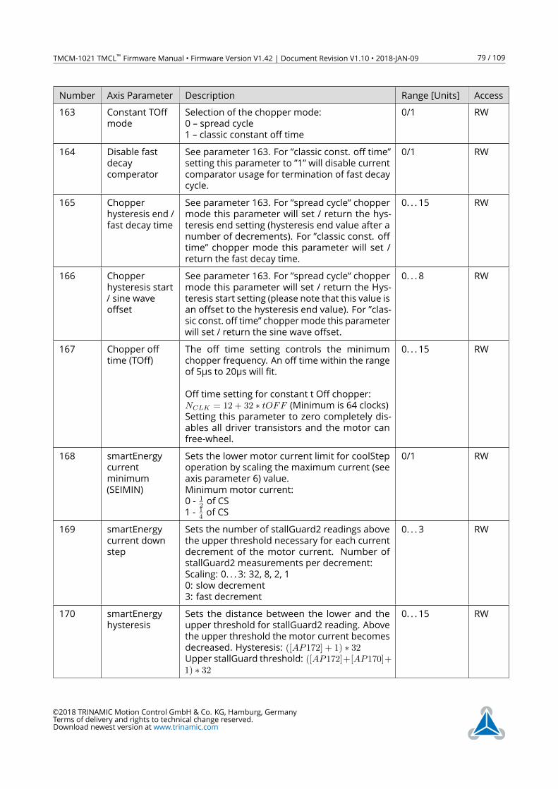
TMCM-1021 TMCL™ Firmware Manual • Firmware Version V1.42 | Document Revision V1.10 • 2018-JAN-09 79 / 109
Number Axis Parameter Description Range [Units] Access
163 Constant TOff
mode
Selection of the chopper mode:
0 – spread cycle
1 – classic constant off time
0/1 RW
164 Disable fast
decay
comperator
See parameter 163. For ”classic const. off time”
setting this parameter to ”1” will disable current
comparator usage for termination of fast decay
cycle.
0/1 RW
165 Chopper
hysteresis end /
fast decay time
See parameter 163. For ”spread cycle” chopper
mode this parameter will set / return the hys-
teresis end setting (hysteresis end value after a
number of decrements). For ”classic const. off
time” chopper mode this parameter will set /
return the fast decay time.
0. . . 15 RW
166 Chopper
hysteresis start
/ sine wave
offset
See parameter 163. For ”spread cycle” chopper
mode this parameter will set / return the Hys-
teresis start setting (please note that this value is
an offset to the hysteresis end value). For ”clas-
sic const. off time” choppermode this parameter
will set / return the sine wave offset.
0. . . 8 RW
167 Chopper off
time (TOff)
The off time setting controls the minimum
chopper frequency. An off time within the range
of 5µs to 20µs will fit.
Off time setting for constant t Off chopper:
NCLK = 12 + 32 ∗ tOFF (Minimum is 64 clocks)Setting this parameter to zero completely dis-
ables all driver transistors and the motor can
free-wheel.
0. . . 15 RW
168 smartEnergy
current
minimum
(SEIMIN)
Sets the lower motor current limit for coolStep
operation by scaling the maximum current (see
axis parameter 6) value.
Minimum motor current:
0 -12 of CS
1 -14 of CS
0/1 RW
169 smartEnergy
current down
step
Sets the number of stallGuard2 readings above
the upper threshold necessary for each current
decrement of the motor current. Number of
stallGuard2 measurements per decrement:
Scaling: 0. . . 3: 32, 8, 2, 1
0: slow decrement
3: fast decrement
0. . . 3 RW
170 smartEnergy
hysteresis
Sets the distance between the lower and the
upper threshold for stallGuard2 reading. Above
the upper threshold the motor current becomes
decreased. Hysteresis: ([AP172] + 1) ∗ 32Upper stallGuard threshold: ([AP172]+[AP170]+1) ∗ 32
0. . . 15 RW
©2018 TRINAMIC Motion Control GmbH & Co. KG, Hamburg, Germany
Terms of delivery and rights to technical change reserved.
Download newest version at www.trinamic.com
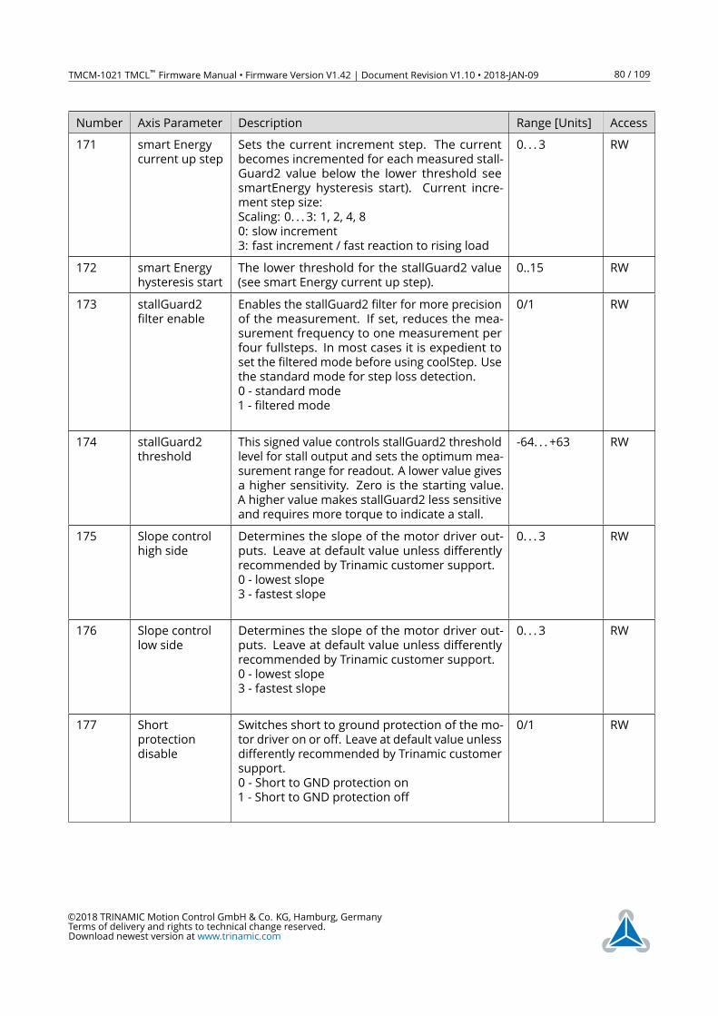
TMCM-1021 TMCL™ Firmware Manual • Firmware Version V1.42 | Document Revision V1.10 • 2018-JAN-09 80 / 109
Number Axis Parameter Description Range [Units] Access
171 smart Energy
current up step
Sets the current increment step. The current
becomes incremented for each measured stall-
Guard2 value below the lower threshold see
smartEnergy hysteresis start). Current incre-
ment step size:
Scaling: 0. . . 3: 1, 2, 4, 8
0: slow increment
3: fast increment / fast reaction to rising load
0. . . 3 RW
172 smart Energy
hysteresis start
The lower threshold for the stallGuard2 value
(see smart Energy current up step).
0..15 RW
173 stallGuard2
filter enable
Enables the stallGuard2 filter for more precision
of the measurement. If set, reduces the mea-
surement frequency to one measurement per
four fullsteps. In most cases it is expedient to
set the filtered mode before using coolStep. Use
the standard mode for step loss detection.
0 - standard mode
1 - filtered mode
0/1 RW
174 stallGuard2
threshold
This signed value controls stallGuard2 threshold
level for stall output and sets the optimum mea-
surement range for readout. A lower value gives
a higher sensitivity. Zero is the starting value.
A higher value makes stallGuard2 less sensitive
and requires more torque to indicate a stall.
-64. . . +63 RW
175 Slope control
high side
Determines the slope of the motor driver out-
puts. Leave at default value unless differently
recommended by Trinamic customer support.
0 - lowest slope
3 - fastest slope
0. . . 3 RW
176 Slope control
low side
Determines the slope of the motor driver out-
puts. Leave at default value unless differently
recommended by Trinamic customer support.
0 - lowest slope
3 - fastest slope
0. . . 3 RW
177 Short
protection
disable
Switches short to ground protection of the mo-
tor driver on or off. Leave at default value unless
differently recommended by Trinamic customer
support.
0 - Short to GND protection on
1 - Short to GND protection off
0/1 RW
©2018 TRINAMIC Motion Control GmbH & Co. KG, Hamburg, Germany
Terms of delivery and rights to technical change reserved.
Download newest version at www.trinamic.com
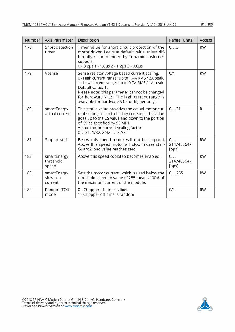
TMCM-1021 TMCL™ Firmware Manual • Firmware Version V1.42 | Document Revision V1.10 • 2018-JAN-09 81 / 109
Number Axis Parameter Description Range [Units] Access
178 Short detection
timer
Timer value for short circuit protection of the
motor driver. Leave at default value unless dif-
ferently recommended by Trinamic customer
support.
0 - 3.2µs 1 - 1.6µs 2 - 1.2µs 3 - 0.8µs
0. . . 3 RW
179 Vsense Sense resistor voltage based current scaling.
0 - High current range: up to 1.4A RMS / 2A peak.
1 - Low current range: up to 0.7A RMS / 1A peak.
Default value: 1.
Please note: this parameter cannot be changed
for hardware V1.2! The high current range is
available for hardware V1.4 or higher only!
0/1 RW
180 smartEnergy
actual current
This status value provides the actual motor cur-
rent setting as controlled by coolStep. The value
goes up to the CS value and down to the portion
of CS as specified by SEIMIN.
Actual motor current scaling factor:
0. . . 31: 1/32, 2/32, . . . 32/32
0. . . 31 R
181 Stop on stall Below this speed motor will not be stopped.
Above this speed motor will stop in case stall-
Guard2 load value reaches zero.
0. . .
2147483647
[pps]
RW
182 smartEnergy
threshold
speed
Above this speed coolStep becomes enabled. 0. . .
2147483647
[pps]
RW
183 smartEnergy
slow run
current
Sets the motor current which is used below the
threshold speed. A value of 255 means 100% of
the maximum current of the module.
0. . . 255 RW
184 Random TOff
mode
0 - Chopper off time is fixed
1 - Chopper off time is random
0/1 RW
©2018 TRINAMIC Motion Control GmbH & Co. KG, Hamburg, Germany
Terms of delivery and rights to technical change reserved.
Download newest version at www.trinamic.com
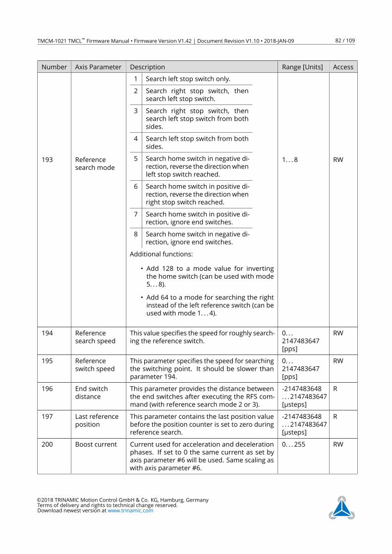
TMCM-1021 TMCL™ Firmware Manual • Firmware Version V1.42 | Document Revision V1.10 • 2018-JAN-09 82 / 109
Number Axis Parameter Description Range [Units] Access
193 Reference
search mode
1 Search left stop switch only.
2 Search right stop switch, then
search left stop switch.
3 Search right stop switch, then
search left stop switch from both
sides.
4 Search left stop switch from both
sides.
5 Search home switch in negative di-
rection, reverse the direction when
left stop switch reached.
6 Search home switch in positive di-
rection, reverse the direction when
right stop switch reached.
7 Search home switch in positive di-
rection, ignore end switches.
8 Search home switch in negative di-
rection, ignore end switches.
Additional functions:
• Add 128 to a mode value for inverting
the home switch (can be used with mode
5. . . 8).
• Add 64 to a mode for searching the right
instead of the left reference switch (can be
used with mode 1. . . 4).
1. . . 8 RW
194 Reference
search speed
This value specifies the speed for roughly search-
ing the reference switch.
0. . .
2147483647
[pps]
RW
195 Reference
switch speed
This parameter specifies the speed for searching
the switching point. It should be slower than
parameter 194.
0. . .
2147483647
[pps]
RW
196 End switch
distance
This parameter provides the distance between
the end switches after executing the RFS com-
mand (with reference search mode 2 or 3).
-2147483648
. . . 2147483647
[µsteps]
R
197 Last reference
position
This parameter contains the last position value
before the position counter is set to zero during
reference search.
-2147483648
. . . 2147483647
[µsteps]
R
200 Boost current Current used for acceleration and deceleration
phases. If set to 0 the same current as set by
axis parameter #6 will be used. Same scaling as
with axis parameter #6.
0. . . 255 RW
©2018 TRINAMIC Motion Control GmbH & Co. KG, Hamburg, Germany
Terms of delivery and rights to technical change reserved.
Download newest version at www.trinamic.com
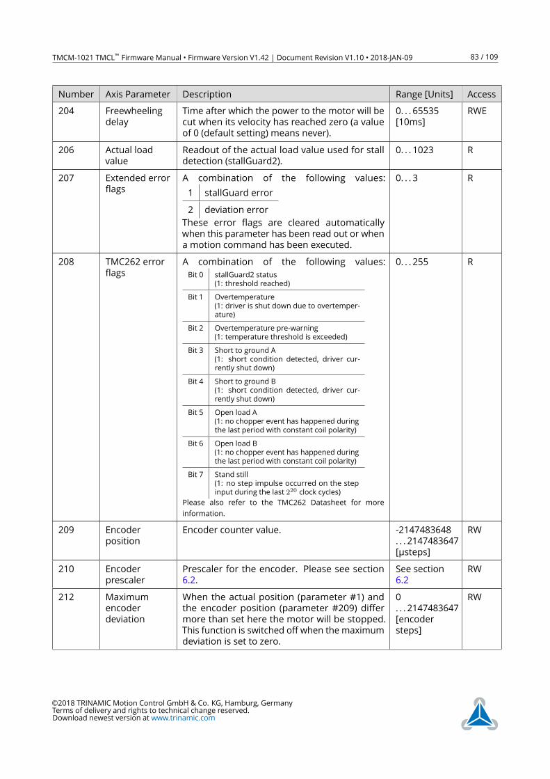
TMCM-1021 TMCL™ Firmware Manual • Firmware Version V1.42 | Document Revision V1.10 • 2018-JAN-09 83 / 109
Number Axis Parameter Description Range [Units] Access
204 Freewheeling
delay
Time after which the power to the motor will be
cut when its velocity has reached zero (a value
of 0 (default setting) means never).
0. . . 65535
[10ms]
RWE
206 Actual load
value
Readout of the actual load value used for stall
detection (stallGuard2).
0. . . 1023 R
207 Extended error
flags
A combination of the following values:
1 stallGuard error
2 deviation error
These error flags are cleared automatically
when this parameter has been read out or when
a motion command has been executed.
0. . . 3 R
208 TMC262 error
flags
A combination of the following values:
Bit 0 stallGuard2 status
(1: threshold reached)
Bit 1 Overtemperature
(1: driver is shut down due to overtemper-
ature)
Bit 2 Overtemperature pre-warning
(1: temperature threshold is exceeded)
Bit 3 Short to ground A
(1: short condition detected, driver cur-
rently shut down)
Bit 4 Short to ground B
(1: short condition detected, driver cur-
rently shut down)
Bit 5 Open load A
(1: no chopper event has happened during
the last period with constant coil polarity)
Bit 6 Open load B
(1: no chopper event has happened during
the last period with constant coil polarity)
Bit 7 Stand still
(1: no step impulse occurred on the step
input during the last 220 clock cycles)
Please also refer to the TMC262 Datasheet for more
information.
0. . . 255 R
209 Encoder
position
Encoder counter value. -2147483648
. . . 2147483647
[µsteps]
RW
210 Encoder
prescaler
Prescaler for the encoder. Please see section
6.2.
See section
6.2
RW
212 Maximum
encoder
deviation
When the actual position (parameter #1) and
the encoder position (parameter #209) differ
more than set here the motor will be stopped.
This function is switched off when the maximum
deviation is set to zero.
0
. . . 2147483647
[encoder
steps]
RW
©2018 TRINAMIC Motion Control GmbH & Co. KG, Hamburg, Germany
Terms of delivery and rights to technical change reserved.
Download newest version at www.trinamic.com
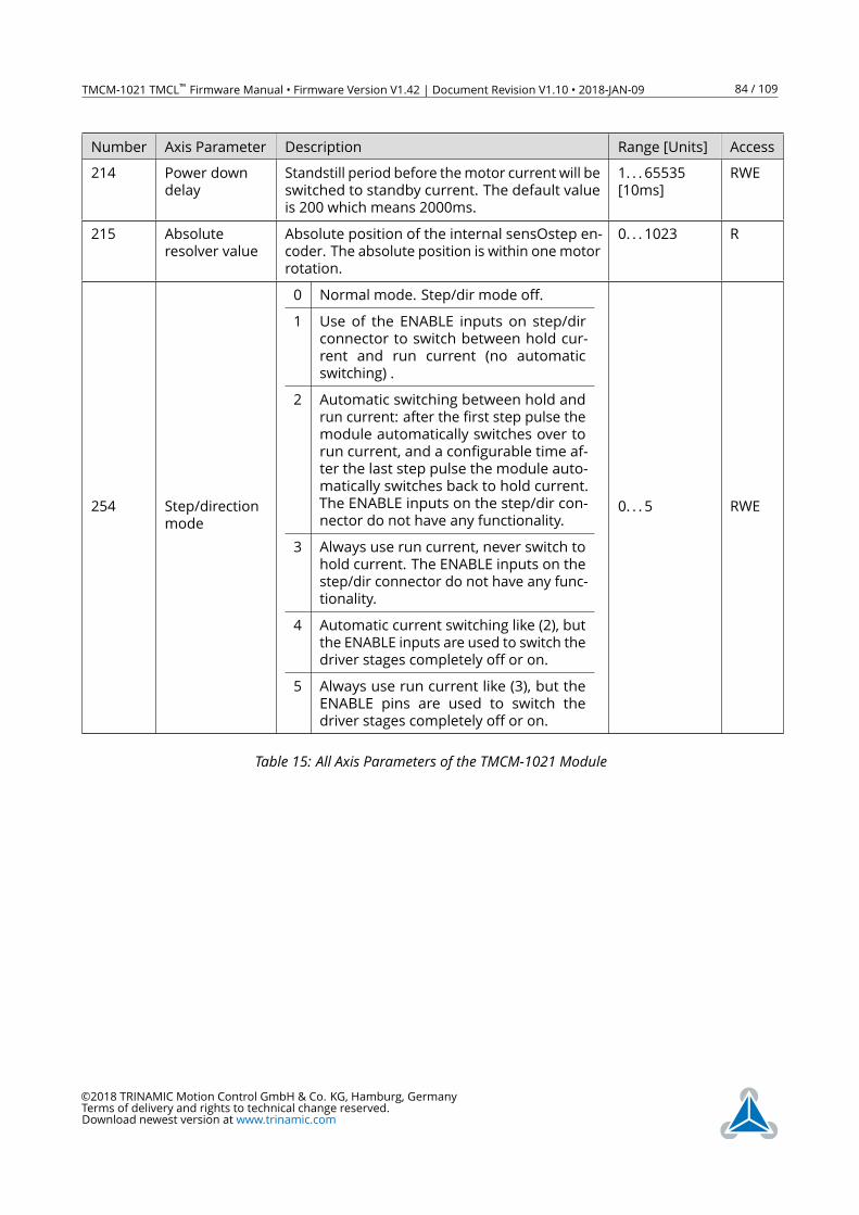
TMCM-1021 TMCL™ Firmware Manual • Firmware Version V1.42 | Document Revision V1.10 • 2018-JAN-09 84 / 109
Number Axis Parameter Description Range [Units] Access
214 Power down
delay
Standstill period before themotor current will be
switched to standby current. The default value
is 200 which means 2000ms.
1. . . 65535
[10ms]
RWE
215 Absolute
resolver value
Absolute position of the internal sensOstep en-
coder. The absolute position is within onemotor
rotation.
0. . . 1023 R
254 Step/direction
mode
0 Normal mode. Step/dir mode off.
1 Use of the ENABLE inputs on step/dir
connector to switch between hold cur-
rent and run current (no automatic
switching) .
2 Automatic switching between hold and
run current: after the first step pulse the
module automatically switches over to
run current, and a configurable time af-
ter the last step pulse the module auto-
matically switches back to hold current.
The ENABLE inputs on the step/dir con-
nector do not have any functionality.
3 Always use run current, never switch to
hold current. The ENABLE inputs on the
step/dir connector do not have any func-
tionality.
4 Automatic current switching like (2), but
the ENABLE inputs are used to switch the
driver stages completely off or on.
5 Always use run current like (3), but the
ENABLE pins are used to switch the
driver stages completely off or on.
0. . . 5 RWE
Table 15: All Axis Parameters of the TMCM-1021 Module
©2018 TRINAMIC Motion Control GmbH & Co. KG, Hamburg, Germany
Terms of delivery and rights to technical change reserved.
Download newest version at www.trinamic.com
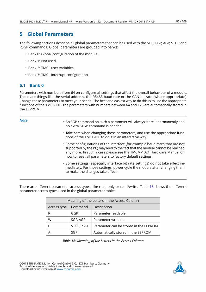
TMCM-1021 TMCL™ Firmware Manual • Firmware Version V1.42 | Document Revision V1.10 • 2018-JAN-09 85 / 109
5 Global Parameters
The following sections describe all global parameters that can be used with the SGP, GGP, AGP, STGP and
RSGP commands. Global parameters are grouped into banks:
• Bank 0: Global configuration of the module.
• Bank 1: Not used.
• Bank 2: TMCL user variables.
• Bank 3: TMCL interrupt configuration.
5.1 Bank 0
Parameters with numbers from 64 on configure all settings that affect the overall behaviour of a module.
These are things like the serial address, the RS485 baud rate or the CAN bit rate (where appropriate).
Change these parameters to meet your needs. The best and easiest way to do this is to use the appropriate
functions of the TMCL-IDE. The parameters with numbers between 64 and 128 are automatically stored in
the EEPROM.
Note• An SGP command on such a parameter will always store it permanently and
no extra STGP command is needed.
• Take care when changing these parameters, and use the appropriate func-
tions of the TMCL-IDE to do it in an interactive way.
• Some configurations of the interface (for example baud rates that are not
supported by the PC)may leed to the fact that themodule cannot be reached
any more. In such a case please see the TMCM-1021 Hardware Manual on
how to reset all parameters to factory default settings.
• Some settings (especially interface bit rate settings) do not take effect im-
mediately. For those settings, power cycle the module after changing them
to make the changes take effect.
There are different parameter access types, like read only or read/write. Table 16 shows the different
parameter access types used in the global parameter tables.
Meaning of the Letters in the Access Column
Access type Command Description
R GGP Parameter readable
W SGP, AGP Parameter writable
E STGP, RSGP Parameter can be stored in the EEPROM
A SGP Automatically stored in the EEPROM
Table 16: Meaning of the Letters in the Access Column
©2018 TRINAMIC Motion Control GmbH & Co. KG, Hamburg, Germany
Terms of delivery and rights to technical change reserved.
Download newest version at www.trinamic.com
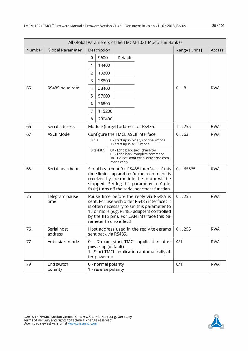
TMCM-1021 TMCL™ Firmware Manual • Firmware Version V1.42 | Document Revision V1.10 • 2018-JAN-09 86 / 109
All Global Parameters of the TMCM-1021 Module in Bank 0
Number Global Parameter Description Range [Units] Access
65 RS485 baud rate
0 9600 Default
1 14400
2 19200
3 28800
4 38400
5 57600
6 76800
7 115200
8 230400
0. . . 8 RWA
66 Serial address Module (target) address for RS485. 1. . . 255 RWA
67 ASCIIMode Configure the TMCL ASCII interface:
Bit 0 0 - start up in binary (normal) mode
1 - start up in ASCIImode
Bits 4 & 5 00 - Echo back each character
01 - Echo back complete command
10 - Do not send echo, only send com-
mand reply
0. . . 63 RWA
68 Serial heartbeat Serial heartbeat for RS485 interface. If this
time limit is up and no further command is
received by the module the motor will be
stopped. Setting this parameter to 0 (de-
fault) turns off the serial heartbeat function.
0. . . 65535 RWA
75 Telegram pause
time
Pause time before the reply via RS485 is
sent. For use with older RS485 interfaces it
is often necessary to set this parameter to
15 or more (e.g. RS485 adapters controlled
by the RTS pin). For CAN interface this pa-
rameter has no effect!
0. . . 255 RWA
76 Serial host
address
Host address used in the reply telegrams
sent back via RS485.
0. . . 255 RWA
77 Auto start mode 0 - Do not start TMCL application after
power up (default).
1 - Start TMCL application automatically af-
ter power up.
0/1 RWA
79 End switch
polarity
0 - normal polarity
1 - reverse polarity
0/1 RWA
©2018 TRINAMIC Motion Control GmbH & Co. KG, Hamburg, Germany
Terms of delivery and rights to technical change reserved.
Download newest version at www.trinamic.com
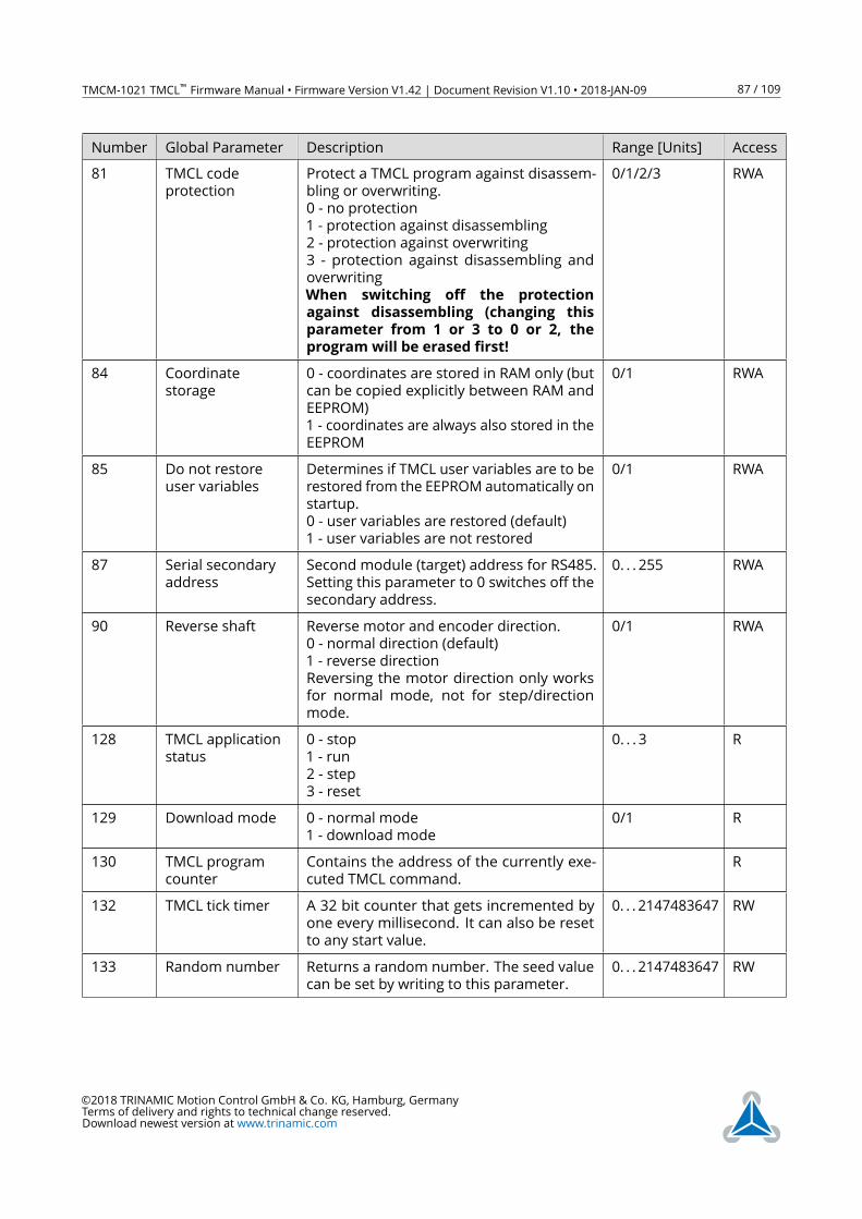
TMCM-1021 TMCL™ Firmware Manual • Firmware Version V1.42 | Document Revision V1.10 • 2018-JAN-09 87 / 109
Number Global Parameter Description Range [Units] Access
81 TMCL code
protection
Protect a TMCL program against disassem-
bling or overwriting.
0 - no protection
1 - protection against disassembling
2 - protection against overwriting
3 - protection against disassembling and
overwriting
When switching off the protection
against disassembling (changing this
parameter from 1 or 3 to 0 or 2, the
program will be erased first!
0/1/2/3 RWA
84 Coordinate
storage
0 - coordinates are stored in RAM only (but
can be copied explicitly between RAM and
EEPROM)
1 - coordinates are always also stored in the
EEPROM
0/1 RWA
85 Do not restore
user variables
Determines if TMCL user variables are to be
restored from the EEPROM automatically on
startup.
0 - user variables are restored (default)
1 - user variables are not restored
0/1 RWA
87 Serial secondary
address
Second module (target) address for RS485.
Setting this parameter to 0 switches off the
secondary address.
0. . . 255 RWA
90 Reverse shaft Reverse motor and encoder direction.
0 - normal direction (default)
1 - reverse direction
Reversing the motor direction only works
for normal mode, not for step/direction
mode.
0/1 RWA
128 TMCL application
status
0 - stop
1 - run
2 - step
3 - reset
0. . . 3 R
129 Download mode 0 - normal mode
1 - download mode
0/1 R
130 TMCL program
counter
Contains the address of the currently exe-
cuted TMCL command.
R
132 TMCL tick timer A 32 bit counter that gets incremented by
one every millisecond. It can also be reset
to any start value.
0. . . 2147483647 RW
133 Random number Returns a random number. The seed value
can be set by writing to this parameter.
0. . . 2147483647 RW
©2018 TRINAMIC Motion Control GmbH & Co. KG, Hamburg, Germany
Terms of delivery and rights to technical change reserved.
Download newest version at www.trinamic.com
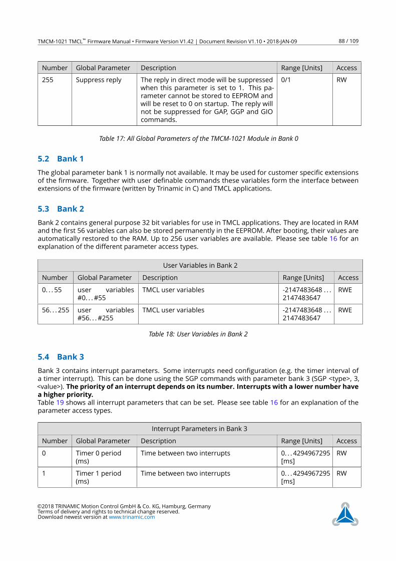
TMCM-1021 TMCL™ Firmware Manual • Firmware Version V1.42 | Document Revision V1.10 • 2018-JAN-09 88 / 109
Number Global Parameter Description Range [Units] Access
255 Suppress reply The reply in direct mode will be suppressed
when this parameter is set to 1. This pa-
rameter cannot be stored to EEPROM and
will be reset to 0 on startup. The reply will
not be suppressed for GAP, GGP and GIO
commands.
0/1 RW
Table 17: All Global Parameters of the TMCM-1021 Module in Bank 0
5.2 Bank 1
The global parameter bank 1 is normally not available. It may be used for customer specific extensions
of the firmware. Together with user definable commands these variables form the interface between
extensions of the firmware (written by Trinamic in C) and TMCL applications.
5.3 Bank 2
Bank 2 contains general purpose 32 bit variables for use in TMCL applications. They are located in RAM
and the first 56 variables can also be stored permanently in the EEPROM. After booting, their values are
automatically restored to the RAM. Up to 256 user variables are available. Please see table 16 for an
explanation of the different parameter access types.
User Variables in Bank 2
Number Global Parameter Description Range [Units] Access
0. . . 55 user variables
#0. . . #55
TMCL user variables -2147483648 . . .
2147483647
RWE
56. . . 255 user variables
#56. . . #255
TMCL user variables -2147483648 . . .
2147483647
RWE
Table 18: User Variables in Bank 2
5.4 Bank 3
Bank 3 contains interrupt parameters. Some interrupts need configuration (e.g. the timer interval of
a timer interrupt). This can be done using the SGP commands with parameter bank 3 (SGP <type>, 3,
<value>). The priority of an interrupt depends on its number. Interrupts with a lower number have
a higher priority.
Table 19 shows all interrupt parameters that can be set. Please see table 16 for an explanation of the
parameter access types.
Interrupt Parameters in Bank 3
Number Global Parameter Description Range [Units] Access
0 Timer 0 period
(ms)
Time between two interrupts 0. . . 4294967295
[ms]
RW
1 Timer 1 period
(ms)
Time between two interrupts 0. . . 4294967295
[ms]
RW
©2018 TRINAMIC Motion Control GmbH & Co. KG, Hamburg, Germany
Terms of delivery and rights to technical change reserved.
Download newest version at www.trinamic.com
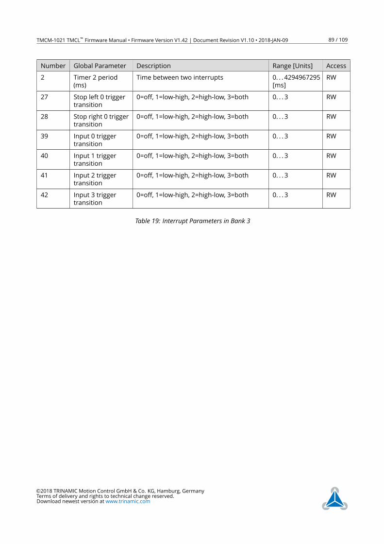
TMCM-1021 TMCL™ Firmware Manual • Firmware Version V1.42 | Document Revision V1.10 • 2018-JAN-09 89 / 109
Number Global Parameter Description Range [Units] Access
2 Timer 2 period
(ms)
Time between two interrupts 0. . . 4294967295
[ms]
RW
27 Stop left 0 trigger
transition
0=off, 1=low-high, 2=high-low, 3=both 0. . . 3 RW
28 Stop right 0 trigger
transition
0=off, 1=low-high, 2=high-low, 3=both 0. . . 3 RW
39 Input 0 trigger
transition
0=off, 1=low-high, 2=high-low, 3=both 0. . . 3 RW
40 Input 1 trigger
transition
0=off, 1=low-high, 2=high-low, 3=both 0. . . 3 RW
41 Input 2 trigger
transition
0=off, 1=low-high, 2=high-low, 3=both 0. . . 3 RW
42 Input 3 trigger
transition
0=off, 1=low-high, 2=high-low, 3=both 0. . . 3 RW
Table 19: Interrupt Parameters in Bank 3
©2018 TRINAMIC Motion Control GmbH & Co. KG, Hamburg, Germany
Terms of delivery and rights to technical change reserved.
Download newest version at www.trinamic.com
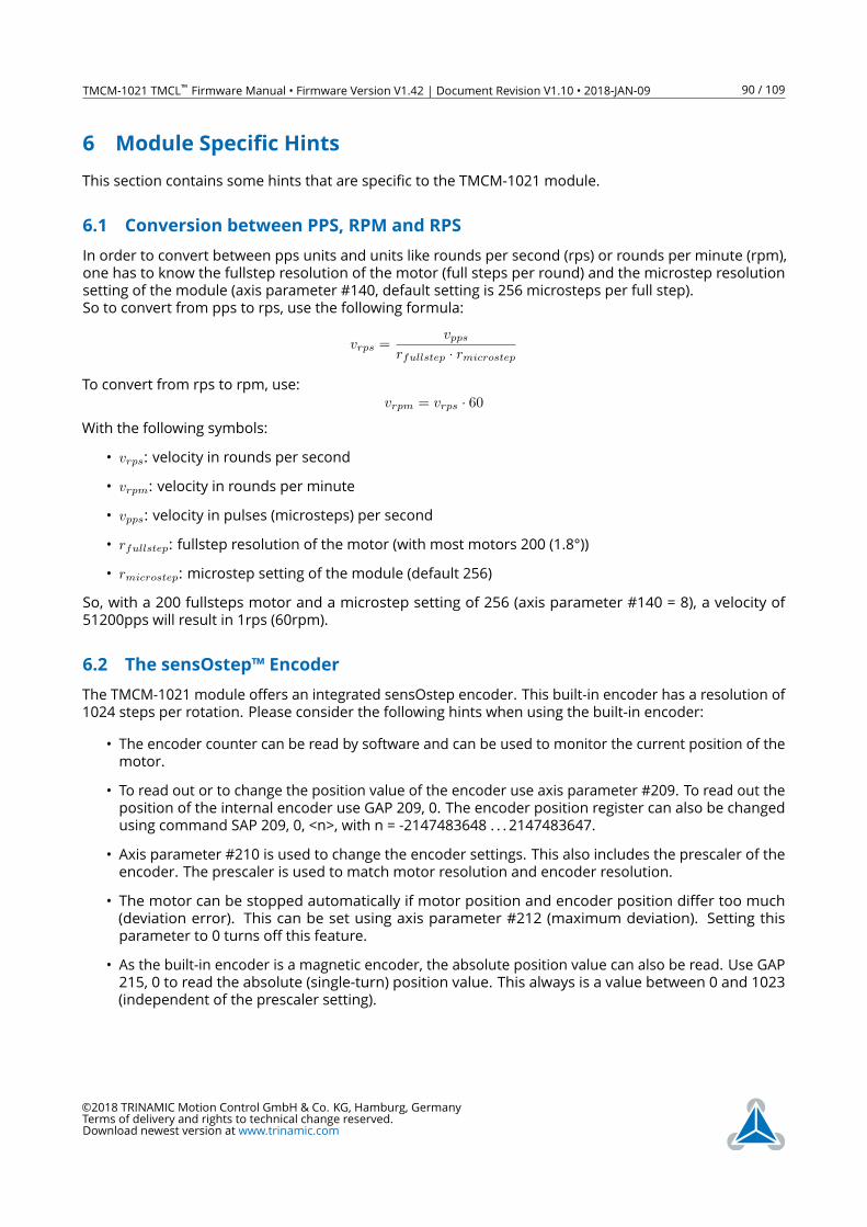
TMCM-1021 TMCL™ Firmware Manual • Firmware Version V1.42 | Document Revision V1.10 • 2018-JAN-09 90 / 109
6 Module Specific Hints
This section contains some hints that are specific to the TMCM-1021 module.
6.1 Conversion between PPS, RPM and RPS
In order to convert between pps units and units like rounds per second (rps) or rounds per minute (rpm),
one has to know the fullstep resolution of the motor (full steps per round) and the microstep resolution
setting of the module (axis parameter #140, default setting is 256 microsteps per full step).
So to convert from pps to rps, use the following formula:
vrps =vpps
rfullstep · rmicrostep
To convert from rps to rpm, use:
vrpm = vrps · 60
With the following symbols:
• vrps: velocity in rounds per second
• vrpm: velocity in rounds per minute
• vpps: velocity in pulses (microsteps) per second
• rfullstep: fullstep resolution of the motor (with most motors 200 (1.8°))
• rmicrostep: microstep setting of the module (default 256)
So, with a 200 fullsteps motor and a microstep setting of 256 (axis parameter #140 = 8), a velocity of
51200pps will result in 1rps (60rpm).
6.2 The sensOstep™ Encoder
The TMCM-1021 module offers an integrated sensOstep encoder. This built-in encoder has a resolution of
1024 steps per rotation. Please consider the following hints when using the built-in encoder:
• The encoder counter can be read by software and can be used to monitor the current position of the
motor.
• To read out or to change the position value of the encoder use axis parameter #209. To read out the
position of the internal encoder use GAP 209, 0. The encoder position register can also be changed
using command SAP 209, 0, <n>, with n = -2147483648 . . . 2147483647.
• Axis parameter #210 is used to change the encoder settings. This also includes the prescaler of the
encoder. The prescaler is used to match motor resolution and encoder resolution.
• The motor can be stopped automatically if motor position and encoder position differ too much
(deviation error). This can be set using axis parameter #212 (maximum deviation). Setting this
parameter to 0 turns off this feature.
• As the built-in encoder is a magnetic encoder, the absolute position value can also be read. Use GAP
215, 0 to read the absolute (single-turn) position value. This always is a value between 0 and 1023
(independent of the prescaler setting).
©2018 TRINAMIC Motion Control GmbH & Co. KG, Hamburg, Germany
Terms of delivery and rights to technical change reserved.
Download newest version at www.trinamic.com
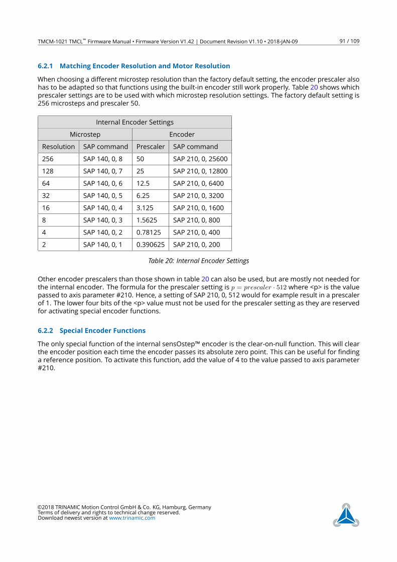
TMCM-1021 TMCL™ Firmware Manual • Firmware Version V1.42 | Document Revision V1.10 • 2018-JAN-09 91 / 109
6.2.1 Matching Encoder Resolution and Motor Resolution
When choosing a different microstep resolution than the factory default setting, the encoder prescaler also
has to be adapted so that functions using the built-in encoder still work properly. Table 20 shows which
prescaler settings are to be used with which microstep resolution settings. The factory default setting is
256 microsteps and prescaler 50.
Internal Encoder Settings
Microstep Encoder
Resolution SAP command Prescaler SAP command
256 SAP 140, 0, 8 50 SAP 210, 0, 25600
128 SAP 140, 0, 7 25 SAP 210, 0, 12800
64 SAP 140, 0, 6 12.5 SAP 210, 0, 6400
32 SAP 140, 0, 5 6.25 SAP 210, 0, 3200
16 SAP 140, 0, 4 3.125 SAP 210, 0, 1600
8 SAP 140, 0, 3 1.5625 SAP 210, 0, 800
4 SAP 140, 0, 2 0.78125 SAP 210, 0, 400
2 SAP 140, 0, 1 0.390625 SAP 210, 0, 200
Table 20: Internal Encoder Settings
Other encoder prescalers than those shown in table 20 can also be used, but are mostly not needed for
the internal encoder. The formula for the prescaler setting is p = prescaler · 512 where <p> is the valuepassed to axis parameter #210. Hence, a setting of SAP 210, 0, 512 would for example result in a prescaler
of 1. The lower four bits of the <p> value must not be used for the prescaler setting as they are reserved
for activating special encoder functions.
6.2.2 Special Encoder Functions
The only special function of the internal sensOstep™ encoder is the clear-on-null function. This will clear
the encoder position each time the encoder passes its absolute zero point. This can be useful for finding
a reference position. To activate this function, add the value of 4 to the value passed to axis parameter
#210.
©2018 TRINAMIC Motion Control GmbH & Co. KG, Hamburg, Germany
Terms of delivery and rights to technical change reserved.
Download newest version at www.trinamic.com
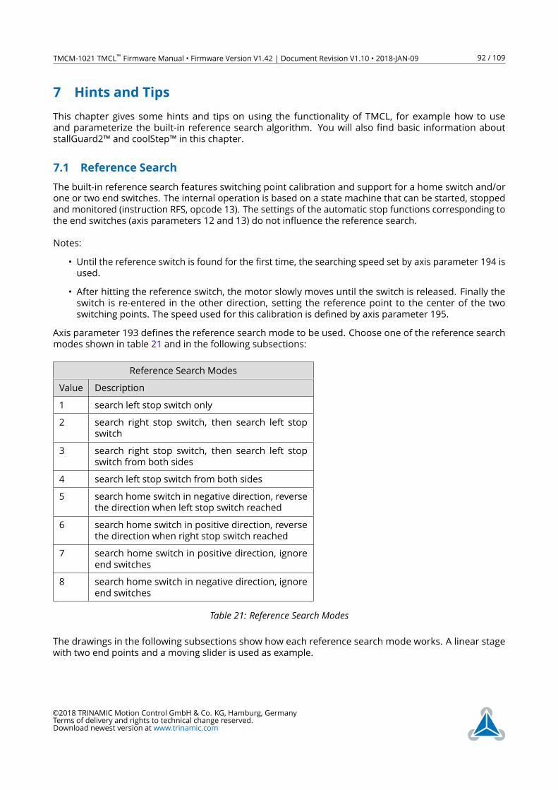
TMCM-1021 TMCL™ Firmware Manual • Firmware Version V1.42 | Document Revision V1.10 • 2018-JAN-09 92 / 109
7 Hints and Tips
This chapter gives some hints and tips on using the functionality of TMCL, for example how to use
and parameterize the built-in reference search algorithm. You will also find basic information about
stallGuard2™ and coolStep™ in this chapter.
7.1 Reference Search
The built-in reference search features switching point calibration and support for a home switch and/or
one or two end switches. The internal operation is based on a state machine that can be started, stopped
and monitored (instruction RFS, opcode 13). The settings of the automatic stop functions corresponding to
the end switches (axis parameters 12 and 13) do not influence the reference search.
Notes:
• Until the reference switch is found for the first time, the searching speed set by axis parameter 194 is
used.
• After hitting the reference switch, the motor slowly moves until the switch is released. Finally the
switch is re-entered in the other direction, setting the reference point to the center of the two
switching points. The speed used for this calibration is defined by axis parameter 195.
Axis parameter 193 defines the reference search mode to be used. Choose one of the reference search
modes shown in table 21 and in the following subsections:
Reference Search Modes
Value Description
1 search left stop switch only
2 search right stop switch, then search left stop
switch
3 search right stop switch, then search left stop
switch from both sides
4 search left stop switch from both sides
5 search home switch in negative direction, reverse
the direction when left stop switch reached
6 search home switch in positive direction, reverse
the direction when right stop switch reached
7 search home switch in positive direction, ignore
end switches
8 search home switch in negative direction, ignore
end switches
Table 21: Reference Search Modes
The drawings in the following subsections show how each reference search mode works. A linear stage
with two end points and a moving slider is used as example.
©2018 TRINAMIC Motion Control GmbH & Co. KG, Hamburg, Germany
Terms of delivery and rights to technical change reserved.
Download newest version at www.trinamic.com
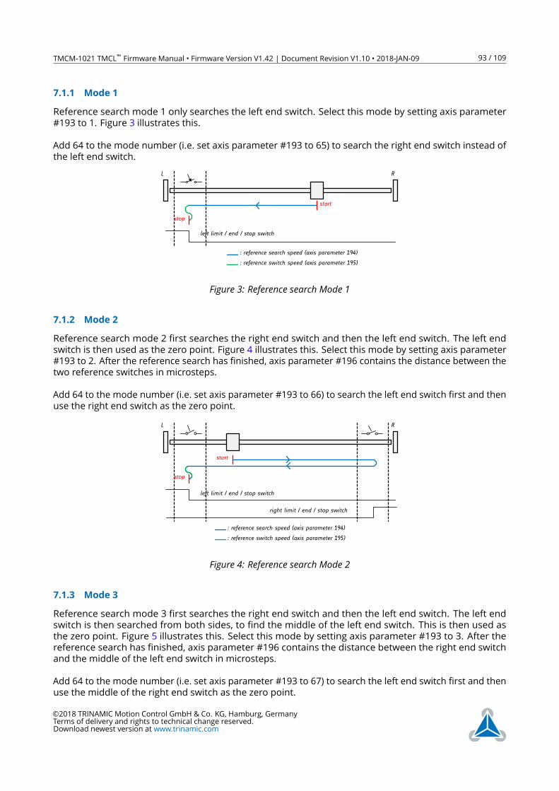
TMCM-1021 TMCL™ Firmware Manual • Firmware Version V1.42 | Document Revision V1.10 • 2018-JAN-09 93 / 109
7.1.1 Mode 1
Reference search mode 1 only searches the left end switch. Select this mode by setting axis parameter
#193 to 1. Figure 3 illustrates this.
Add 64 to the mode number (i.e. set axis parameter #193 to 65) to search the right end switch instead of
the left end switch.
left limit / end / stop switch
L R
start
stop
: reference search speed (axis parameter 194)
: reference switch speed (axis parameter 195)
Figure 3: Reference search Mode 1
7.1.2 Mode 2
Reference search mode 2 first searches the right end switch and then the left end switch. The left end
switch is then used as the zero point. Figure 4 illustrates this. Select this mode by setting axis parameter
#193 to 2. After the reference search has finished, axis parameter #196 contains the distance between the
two reference switches in microsteps.
Add 64 to the mode number (i.e. set axis parameter #193 to 66) to search the left end switch first and then
use the right end switch as the zero point.
left limit / end / stop switch
L R
right limit / end / stop switch
start
stop
: reference search speed (axis parameter 194)
: reference switch speed (axis parameter 195)
Figure 4: Reference search Mode 2
7.1.3 Mode 3
Reference search mode 3 first searches the right end switch and then the left end switch. The left end
switch is then searched from both sides, to find the middle of the left end switch. This is then used as
the zero point. Figure 5 illustrates this. Select this mode by setting axis parameter #193 to 3. After the
reference search has finished, axis parameter #196 contains the distance between the right end switch
and the middle of the left end switch in microsteps.
Add 64 to the mode number (i.e. set axis parameter #193 to 67) to search the left end switch first and then
use the middle of the right end switch as the zero point.
©2018 TRINAMIC Motion Control GmbH & Co. KG, Hamburg, Germany
Terms of delivery and rights to technical change reserved.
Download newest version at www.trinamic.com
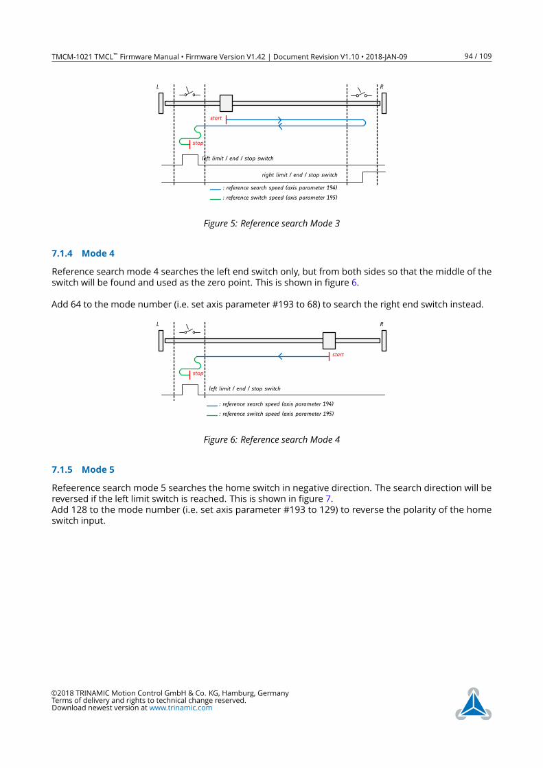
TMCM-1021 TMCL™ Firmware Manual • Firmware Version V1.42 | Document Revision V1.10 • 2018-JAN-09 94 / 109
left limit / end / stop switch
L R
right limit / end / stop switch
start
stop
: reference search speed (axis parameter 194)
: reference switch speed (axis parameter 195)
Figure 5: Reference search Mode 3
7.1.4 Mode 4
Reference search mode 4 searches the left end switch only, but from both sides so that the middle of the
switch will be found and used as the zero point. This is shown in figure 6.
Add 64 to the mode number (i.e. set axis parameter #193 to 68) to search the right end switch instead.
left limit / end / stop switch
L R
stop
: reference search speed (axis parameter 194)
: reference switch speed (axis parameter 195)
start
Figure 6: Reference search Mode 4
7.1.5 Mode 5
Refeerence search mode 5 searches the home switch in negative direction. The search direction will be
reversed if the left limit switch is reached. This is shown in figure 7.
Add 128 to the mode number (i.e. set axis parameter #193 to 129) to reverse the polarity of the home
switch input.
©2018 TRINAMIC Motion Control GmbH & Co. KG, Hamburg, Germany
Terms of delivery and rights to technical change reserved.
Download newest version at www.trinamic.com
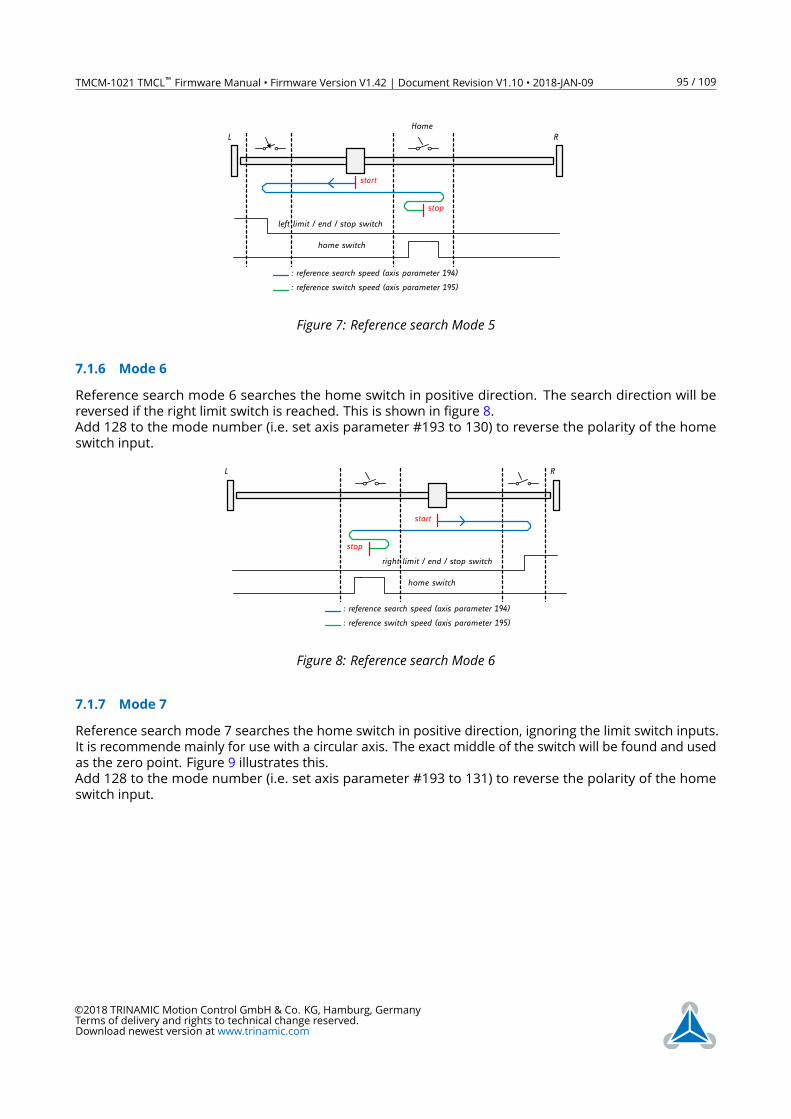
TMCM-1021 TMCL™ Firmware Manual • Firmware Version V1.42 | Document Revision V1.10 • 2018-JAN-09 95 / 109
left limit / end / stop switch
L R
start
stop
: reference search speed (axis parameter 194)
: reference switch speed (axis parameter 195)
Home
home switch
Figure 7: Reference search Mode 5
7.1.6 Mode 6
Reference search mode 6 searches the home switch in positive direction. The search direction will be
reversed if the right limit switch is reached. This is shown in figure 8.
Add 128 to the mode number (i.e. set axis parameter #193 to 130) to reverse the polarity of the home
switch input.
L R
right limit / end / stop switch
: reference search speed (axis parameter 194)
: reference switch speed (axis parameter 195)
start
stop
home switch
Figure 8: Reference search Mode 6
7.1.7 Mode 7
Reference search mode 7 searches the home switch in positive direction, ignoring the limit switch inputs.
It is recommende mainly for use with a circular axis. The exact middle of the switch will be found and used
as the zero point. Figure 9 illustrates this.
Add 128 to the mode number (i.e. set axis parameter #193 to 131) to reverse the polarity of the home
switch input.
©2018 TRINAMIC Motion Control GmbH & Co. KG, Hamburg, Germany
Terms of delivery and rights to technical change reserved.
Download newest version at www.trinamic.com
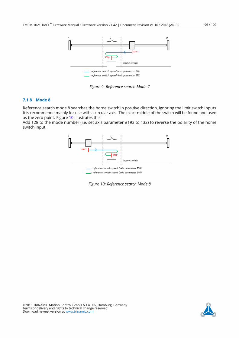
TMCM-1021 TMCL™ Firmware Manual • Firmware Version V1.42 | Document Revision V1.10 • 2018-JAN-09 96 / 109
L R
: reference search speed (axis parameter 194)
: reference switch speed (axis parameter 195)
start
stop
home switch
Figure 9: Reference search Mode 7
7.1.8 Mode 8
Reference search mode 8 searches the home switch in positive direction, ignoring the limit switch inputs.
It is recommende mainly for use with a circular axis. The exact middle of the switch will be found and used
as the zero point. Figure 10 illustrates this.
Add 128 to the mode number (i.e. set axis parameter #193 to 132) to reverse the polarity of the home
switch input.
L R
: reference search speed (axis parameter 194)
: reference switch speed (axis parameter 195)
start
stop
home switch
Figure 10: Reference search Mode 8
©2018 TRINAMIC Motion Control GmbH & Co. KG, Hamburg, Germany
Terms of delivery and rights to technical change reserved.
Download newest version at www.trinamic.com
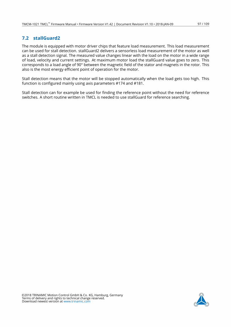
TMCM-1021 TMCL™ Firmware Manual • Firmware Version V1.42 | Document Revision V1.10 • 2018-JAN-09 97 / 109
7.2 stallGuard2
The module is equipped with motor driver chips that feature load measurement. This load measurement
can be used for stall detection. stallGuard2 delivers a sensorless load measurement of the motor as well
as a stall detection signal. The measured value changes linear with the load on the motor in a wide range
of load, velocity and current settings. At maximum motor load the stallGuard value goes to zero. This
corresponds to a load angle of 90° between the magnetic field of the stator and magnets in the rotor. This
also is the most energy efficient point of operation for the motor.
Stall detection means that the motor will be stopped automatically when the load gets too high. This
function is configured mainly using axis parameters #174 and #181.
Stall detection can for example be used for finding the reference point without the need for reference
switches. A short routine written in TMCL is needed to use stallGuard for reference searching.
©2018 TRINAMIC Motion Control GmbH & Co. KG, Hamburg, Germany
Terms of delivery and rights to technical change reserved.
Download newest version at www.trinamic.com
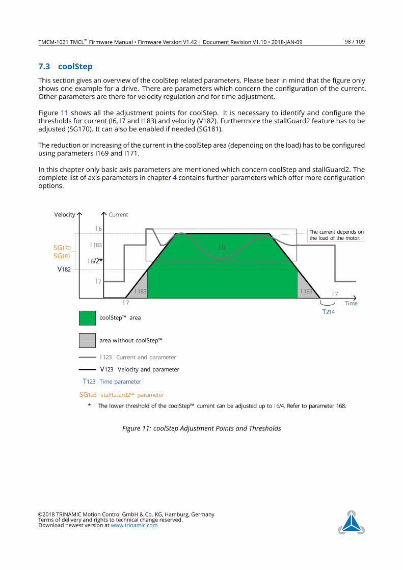
TMCM-1021 TMCL™ Firmware Manual • Firmware Version V1.42 | Document Revision V1.10 • 2018-JAN-09 98 / 109
7.3 coolStep
This section gives an overview of the coolStep related parameters. Please bear in mind that the figure only
shows one example for a drive. There are parameters which concern the configuration of the current.
Other parameters are there for velocity regulation and for time adjustment.
Figure 11 shows all the adjustment points for coolStep. It is necessary to identify and configure the
thresholds for current (I6, I7 and I183) and velocity (V182). Furthermore the stallGuard2 feature has to be
adjusted (SG170). It can also be enabled if needed (SG181).
The reduction or increasing of the current in the coolStep area (depending on the load) has to be configured
using parameters I169 and I171.
In this chapter only basic axis parameters are mentioned which concern coolStep and stallGuard2. The
complete list of axis parameters in chapter 4 contains further parameters which offer more configuration
options.
Velocity
TimeT214
coolStep™ area
I 7I 7
area without coolStep™
SG170SG181
V182
I 6
I 183 I 183
Current
V123 Velocity and parameter
I 123 Current and parameter
T123 Time parameter
I 7
I 6
I 183
I 6/2*
* The lower threshold of the coolStep™ current can be adjusted up to I6/4. Refer to parameter 168.
The current depends on the load of the motor.
SG123 stallGuard2™ parameter
Figure 11: coolStep Adjustment Points and Thresholds
©2018 TRINAMIC Motion Control GmbH & Co. KG, Hamburg, Germany
Terms of delivery and rights to technical change reserved.
Download newest version at www.trinamic.com
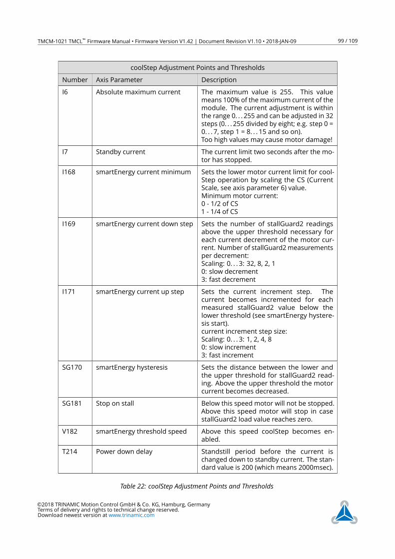
TMCM-1021 TMCL™ Firmware Manual • Firmware Version V1.42 | Document Revision V1.10 • 2018-JAN-09 99 / 109
coolStep Adjustment Points and Thresholds
Number Axis Parameter Description
I6 Absolute maximum current The maximum value is 255. This value
means 100% of the maximum current of the
module. The current adjustment is within
the range 0. . . 255 and can be adjusted in 32
steps (0. . . 255 divided by eight; e.g. step 0 =
0. . . 7, step 1 = 8. . . 15 and so on).
Too high values may cause motor damage!
I7 Standby current The current limit two seconds after the mo-
tor has stopped.
I168 smartEnergy current minimum Sets the lower motor current limit for cool-
Step operation by scaling the CS (Current
Scale, see axis parameter 6) value.
Minimum motor current:
0 - 1/2 of CS
1 - 1/4 of CS
I169 smartEnergy current down step Sets the number of stallGuard2 readings
above the upper threshold necessary for
each current decrement of the motor cur-
rent. Number of stallGuard2measurements
per decrement:
Scaling: 0. . . 3: 32, 8, 2, 1
0: slow decrement
3: fast decrement
I171 smartEnergy current up step Sets the current increment step. The
current becomes incremented for each
measured stallGuard2 value below the
lower threshold (see smartEnergy hystere-
sis start).
current increment step size:
Scaling: 0. . . 3: 1, 2, 4, 8
0: slow increment
3: fast increment
SG170 smartEnergy hysteresis Sets the distance between the lower and
the upper threshold for stallGuard2 read-
ing. Above the upper threshold the motor
current becomes decreased.
SG181 Stop on stall Below this speed motor will not be stopped.
Above this speed motor will stop in case
stallGuard2 load value reaches zero.
V182 smartEnergy threshold speed Above this speed coolStep becomes en-
abled.
T214 Power down delay Standstill period before the current is
changed down to standby current. The stan-
dard value is 200 (which means 2000msec).
Table 22: coolStep Adjustment Points and Thresholds
©2018 TRINAMIC Motion Control GmbH & Co. KG, Hamburg, Germany
Terms of delivery and rights to technical change reserved.
Download newest version at www.trinamic.com
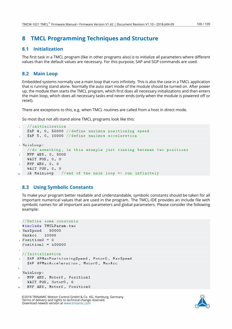
TMCM-1021 TMCL™ Firmware Manual • Firmware Version V1.42 | Document Revision V1.10 • 2018-JAN-09 100 / 109
8 TMCL Programming Techniques and Structure
8.1 Initialization
The first task in a TMCL program (like in other programs also) is to initialize all parameters where different
values than the default values are necessary. For this purpose, SAP and SGP commands are used.
8.2 Main Loop
Embedded systems normally use a main loop that runs infinitely. This is also the case in a TMCL application
that is running stand alone. Normally the auto start mode of the module should be turned on. After power
up, the module then starts the TMCL program, which first does all necessary initializations and then enters
the main loop, which does all necessary tasks end never ends (only when the module is powered off or
reset).
There are exceptions to this, e.g. when TMCL routines are called from a host in direct mode.
So most (but not all) stand alone TMCL programs look like this:
1 // Initialization
SAP 4, 0, 50000 // define maximum positioning speed
3 SAP 5, 0, 10000 // define maximum acceleration
5 MainLoop:
//do something , in this example just running between two positions
7 MVP ABS , 0, 5000
WAIT POS , 0, 0
9 MVP ABS , 0, 0
WAIT POS , 0, 0
11 JA MainLoop //end of the main loop => run infinitely
8.3 Using Symbolic Constants
To make your program better readable and understandable, symbolic constants should be taken for all
important numerical values that are used in the program. The TMCL-IDE provides an include file with
symbolic names for all important axis parameters and global parameters. Please consider the following
example:
1 // Define some constants
#include TMCLParam.tmc
3 MaxSpeed = 50000
MaxAcc = 10000
5 Position0 = 0
Position1 = 500000
7
// Initialization
9 SAP APMaxPositioningSpeed , Motor0 , MaxSpeed
SAP APMaxAcceleration , Motor0 , MaxAcc
11
MainLoop:
13 MVP ABS , Motor0 , Position1
WAIT POS , Motor0 , 0
15 MVP ABS , Motor0 , Position0
©2018 TRINAMIC Motion Control GmbH & Co. KG, Hamburg, Germany
Terms of delivery and rights to technical change reserved.
Download newest version at www.trinamic.com
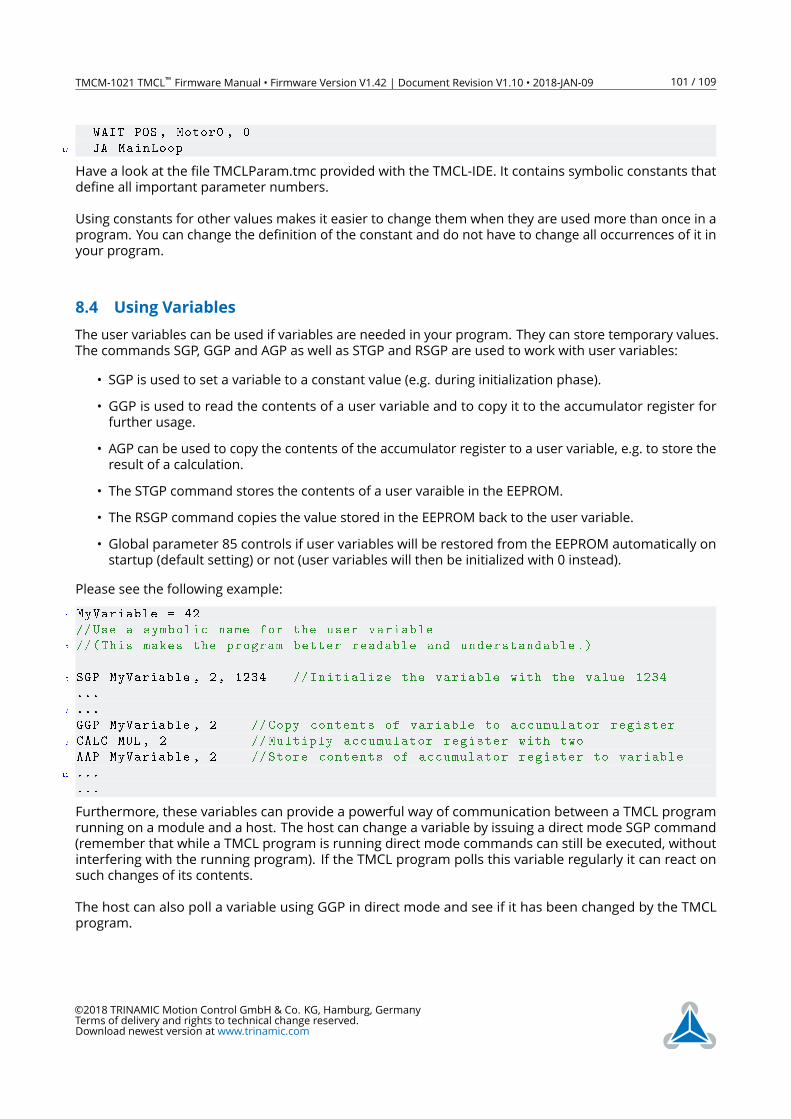
TMCM-1021 TMCL™ Firmware Manual • Firmware Version V1.42 | Document Revision V1.10 • 2018-JAN-09 101 / 109
WAIT POS , Motor0 , 0
17 JA MainLoop
Have a look at the file TMCLParam.tmc provided with the TMCL-IDE. It contains symbolic constants that
define all important parameter numbers.
Using constants for other values makes it easier to change them when they are used more than once in a
program. You can change the definition of the constant and do not have to change all occurrences of it in
your program.
8.4 Using Variables
The user variables can be used if variables are needed in your program. They can store temporary values.
The commands SGP, GGP and AGP as well as STGP and RSGP are used to work with user variables:
• SGP is used to set a variable to a constant value (e.g. during initialization phase).
• GGP is used to read the contents of a user variable and to copy it to the accumulator register for
further usage.
• AGP can be used to copy the contents of the accumulator register to a user variable, e.g. to store the
result of a calculation.
• The STGP command stores the contents of a user varaible in the EEPROM.
• The RSGP command copies the value stored in the EEPROM back to the user variable.
• Global parameter 85 controls if user variables will be restored from the EEPROM automatically on
startup (default setting) or not (user variables will then be initialized with 0 instead).
Please see the following example:
1 MyVariable = 42
//Use a symbolic name for the user variable
3 //(This makes the program better readable and understandable .)
5 SGP MyVariable , 2, 1234 // Initialize the variable with the value 1234
...
7 ...
GGP MyVariable , 2 //Copy contents of variable to accumulator register
9 CALC MUL , 2 // Multiply accumulator register with two
AAP MyVariable , 2 //Store contents of accumulator register to variable
11 ...
...
Furthermore, these variables can provide a powerful way of communication between a TMCL program
running on a module and a host. The host can change a variable by issuing a direct mode SGP command
(remember that while a TMCL program is running direct mode commands can still be executed, without
interfering with the running program). If the TMCL program polls this variable regularly it can react on
such changes of its contents.
The host can also poll a variable using GGP in direct mode and see if it has been changed by the TMCL
program.
©2018 TRINAMIC Motion Control GmbH & Co. KG, Hamburg, Germany
Terms of delivery and rights to technical change reserved.
Download newest version at www.trinamic.com
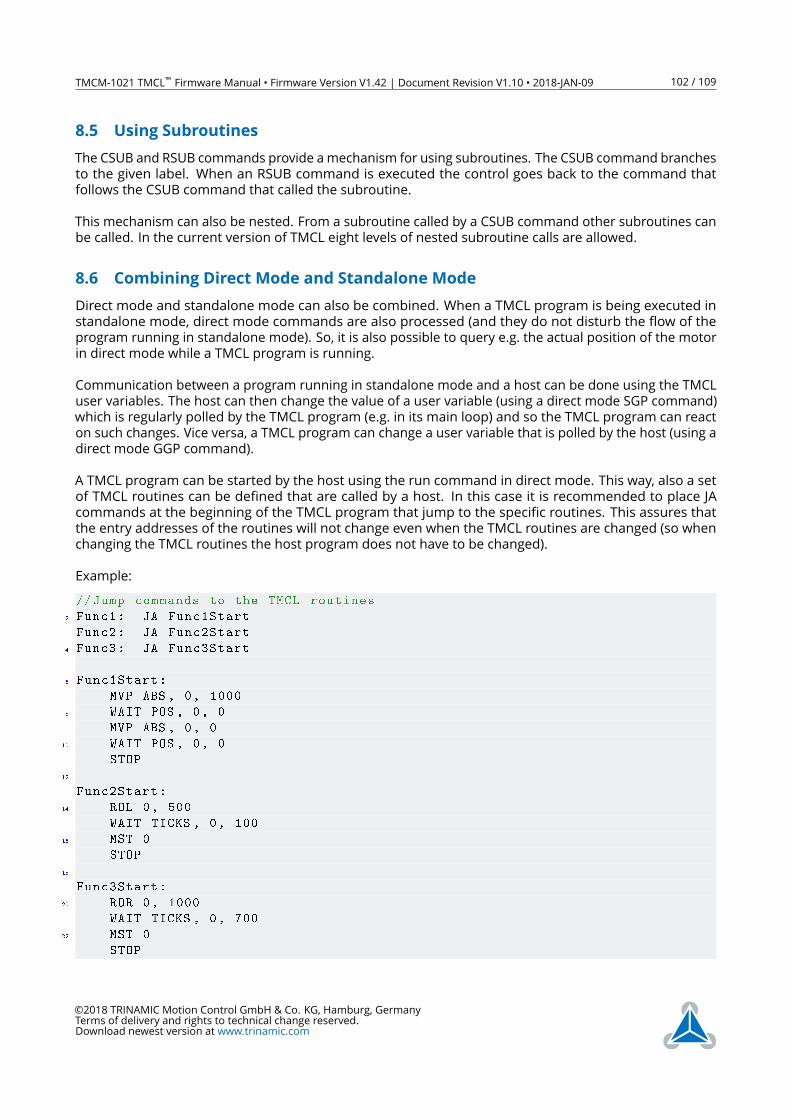
TMCM-1021 TMCL™ Firmware Manual • Firmware Version V1.42 | Document Revision V1.10 • 2018-JAN-09 102 / 109
8.5 Using Subroutines
The CSUB and RSUB commands provide amechanism for using subroutines. The CSUB command branches
to the given label. When an RSUB command is executed the control goes back to the command that
follows the CSUB command that called the subroutine.
This mechanism can also be nested. From a subroutine called by a CSUB command other subroutines can
be called. In the current version of TMCL eight levels of nested subroutine calls are allowed.
8.6 Combining Direct Mode and Standalone Mode
Direct mode and standalone mode can also be combined. When a TMCL program is being executed in
standalone mode, direct mode commands are also processed (and they do not disturb the flow of the
program running in standalone mode). So, it is also possible to query e.g. the actual position of the motor
in direct mode while a TMCL program is running.
Communication between a program running in standalone mode and a host can be done using the TMCL
user variables. The host can then change the value of a user variable (using a direct mode SGP command)
which is regularly polled by the TMCL program (e.g. in its main loop) and so the TMCL program can react
on such changes. Vice versa, a TMCL program can change a user variable that is polled by the host (using a
direct mode GGP command).
A TMCL program can be started by the host using the run command in direct mode. This way, also a set
of TMCL routines can be defined that are called by a host. In this case it is recommended to place JA
commands at the beginning of the TMCL program that jump to the specific routines. This assures that
the entry addresses of the routines will not change even when the TMCL routines are changed (so when
changing the TMCL routines the host program does not have to be changed).
Example:
//Jump commands to the TMCL routines
2 Func1: JA Func1Start
Func2: JA Func2Start
4 Func3: JA Func3Start
6 Func1Start:
MVP ABS , 0, 1000
8 WAIT POS , 0, 0
MVP ABS , 0, 0
10 WAIT POS , 0, 0
STOP
12
Func2Start:
14 ROL 0, 500
WAIT TICKS , 0, 100
16 MST 0
STOP
18
Func3Start:
20 ROR 0, 1000
WAIT TICKS , 0, 700
22 MST 0
STOP
©2018 TRINAMIC Motion Control GmbH & Co. KG, Hamburg, Germany
Terms of delivery and rights to technical change reserved.
Download newest version at www.trinamic.com
TMCM-1021 TMCL™ Firmware Manual • Firmware Version V1.42 | Document Revision V1.10 • 2018-JAN-09 103 / 109
This example provides three very simple TMCL routines. They can be called from a host by issuing a run
command with address 0 to call the first function, or a run command with address 1 to call the second
function, or a run command with address 2 to call the third function. You can see the addresses of the
TMCL labels (that are needed for the run commands) by using the ”Generate symbol file function” of the
TMCL-IDE.
8.7 Make the TMCL Program start automatically
For stand-alone operation the module has to start the TMCL program in its memory automatically after
power-on. In order to achieve this, switch on the Autostart option of the module. This is controlled by
global parameter #77. There are different ways to switch on the Autostart option:
• Execute the command SGP 77, 0, 1 in direct mode (using the Direct Mode tool in the TMCL-IDE).
• Use the Global Parameters tool in the TMCL-IDE to set global parameter #77 to 1.
• Use the Autostart entry in the TMCL menu of the TMCL Creator in the TMCL-IDE. Go to the Autostart
entry in the TMCL menu and select "’On"’.
©2018 TRINAMIC Motion Control GmbH & Co. KG, Hamburg, Germany
Terms of delivery and rights to technical change reserved.
Download newest version at www.trinamic.com
TMCM-1021 TMCL™ Firmware Manual • Firmware Version V1.42 | Document Revision V1.10 • 2018-JAN-09 104 / 109
9 Figures Index
1 stallGuard2 Load Measurement as a
Function of Load . . . . . . . . . . . . 6
2 Energy Efficiency Example with coolStep 6
3 Reference search Mode 1 . . . . . . . 93
4 Reference search Mode 2 . . . . . . . 93
5 Reference search Mode 3 . . . . . . . 94
6 Reference search Mode 4 . . . . . . . 94
7 Reference search Mode 5 . . . . . . . 95
8 Reference search Mode 6 . . . . . . . 95
9 Reference search Mode 7 . . . . . . . 96
10 Reference search Mode 8 . . . . . . . 96
11 coolStep Adjustment Points and
Thresholds . . . . . . . . . . . . . . . . 98
©2018 TRINAMIC Motion Control GmbH & Co. KG, Hamburg, Germany
Terms of delivery and rights to technical change reserved.
Download newest version at www.trinamic.com
TMCM-1021 TMCL™ Firmware Manual • Firmware Version V1.42 | Document Revision V1.10 • 2018-JAN-09 105 / 109
10 Tables Index
1 Most important Axis Parameters . . . 8
2 TMCL Command Format . . . . . . . . 11
3 TMCL Reply Format . . . . . . . . . . . 12
4 TMCL Status Codes . . . . . . . . . . . 12
5 Overview of all TMCL Commands . . . 17
6 Motion Commands . . . . . . . . . . . 18
7 Parameter Commands . . . . . . . . . 18
8 Branch Commands . . . . . . . . . . . 19
9 I/O Port Commands . . . . . . . . . . 19
10 Calculation Commands . . . . . . . . 19
11 Interrupt Processing Commands . . . 20
12 Interrupt Vectors . . . . . . . . . . . . 21
13 TMCL Control Commands . . . . . . . 75
14 Meaning of the Letters in the Access
Column . . . . . . . . . . . . . . . . . . 76
15 All Axis Parameters of the TMCM-1021
Module . . . . . . . . . . . . . . . . . . 84
16 Meaning of the Letters in the Access
Column . . . . . . . . . . . . . . . . . . 85
17 All Global Parameters of the TMCM-
1021 Module in Bank 0 . . . . . . . . . 88
18 User Variables in Bank 2 . . . . . . . . 88
19 Interrupt Parameters in Bank 3 . . . . 89
20 Internal Encoder Settings . . . . . . . 91
21 Reference Search Modes . . . . . . . . 92
22 coolStep Adjustment Points and
Thresholds . . . . . . . . . . . . . . . . 99
23 Firmware Revision . . . . . . . . . . . 108
24 Document Revision . . . . . . . . . . . 109
©2018 TRINAMIC Motion Control GmbH & Co. KG, Hamburg, Germany
Terms of delivery and rights to technical change reserved.
Download newest version at www.trinamic.com

TMCM-1021 TMCL™ Firmware Manual • Firmware Version V1.42 | Document Revision V1.10 • 2018-JAN-09 106 / 109
11 Supplemental Directives
11.1 Producer Information
11.2 Copyright
TRINAMIC owns the content of this user manual in its entirety, including but not limited to pictures, logos,
trademarks, and resources. © Copyright 2018 TRINAMIC. All rights reserved. Electronically published by
TRINAMIC, Germany.
Redistributions of source or derived format (for example, Portable Document Format or Hypertext Markup
Language) must retain the above copyright notice, and the complete Datasheet User Manual docu-
mentation of this product including associated Application Notes; and a reference to other available
product-related documentation.
11.3 Trademark Designations and Symbols
Trademark designations and symbols used in this documentation indicate that a product or feature is
owned and registered as trademark and/or patent either by TRINAMIC or by other manufacturers, whose
products are used or referred to in combination with TRINAMIC’s products and TRINAMIC’s product docu-
mentation.
This TMCL™ Firmware Manual is a non-commercial publication that seeks to provide concise scientific
and technical user information to the target user. Thus, trademark designations and symbols are only
entered in the Short Spec of this document that introduces the product at a quick glance. The trademark
designation /symbol is also entered when the product or feature name occurs for the first time in the
document. All trademarks and brand names used are property of their respective owners.
11.4 Target User
The documentation provided here, is for programmers and engineers only, who are equipped with the
necessary skills and have been trained to work with this type of product.
The Target User knows how to responsibly make use of this product without causing harm to himself or
others, and without causing damage to systems or devices, in which the user incorporates the product.
11.5 Disclaimer: Life Support Systems
TRINAMIC Motion Control GmbH & Co. KG does not authorize or warrant any of its products for use in life
support systems, without the specific written consent of TRINAMIC Motion Control GmbH & Co. KG.
Life support systems are equipment intended to support or sustain life, and whose failure to perform,
when properly used in accordance with instructions provided, can be reasonably expected to result in
personal injury or death.
Information given in this document is believed to be accurate and reliable. However, no responsibility
is assumed for the consequences of its use nor for any infringement of patents or other rights of third
parties which may result from its use. Specifications are subject to change without notice.
11.6 Disclaimer: Intended Use
The data specified in this user manual is intended solely for the purpose of product description. No repre-
sentations or warranties, either express or implied, of merchantability, fitness for a particular purpose
©2018 TRINAMIC Motion Control GmbH & Co. KG, Hamburg, Germany
Terms of delivery and rights to technical change reserved.
Download newest version at www.trinamic.com
TMCM-1021 TMCL™ Firmware Manual • Firmware Version V1.42 | Document Revision V1.10 • 2018-JAN-09 107 / 109
or of any other nature are made hereunder with respect to information/specification or the products to
which information refers and no guarantee with respect to compliance to the intended use is given.
In particular, this also applies to the stated possible applications or areas of applications of the product.
TRINAMIC products are not designed for and must not be used in connection with any applications where
the failure of such products would reasonably be expected to result in significant personal injury or death
(safety-Critical Applications) without TRINAMIC’s specific written consent.
TRINAMIC products are not designed nor intended for use in military or aerospace applications or environ-
ments or in automotive applications unless specifically designated for such use by TRINAMIC. TRINAMIC
conveys no patent, copyright, mask work right or other trademark right to this product. TRINAMIC assumes
no liability for any patent and/or other trade mark rights of a third party resulting from processing or
handling of the product and/or any other use of the product.
11.7 Collateral Documents & Tools
This product documentation is related and/or associated with additional tool kits, firmware and other
items, as provided on the product page at: www.trinamic.com.
©2018 TRINAMIC Motion Control GmbH & Co. KG, Hamburg, Germany
Terms of delivery and rights to technical change reserved.
Download newest version at www.trinamic.com
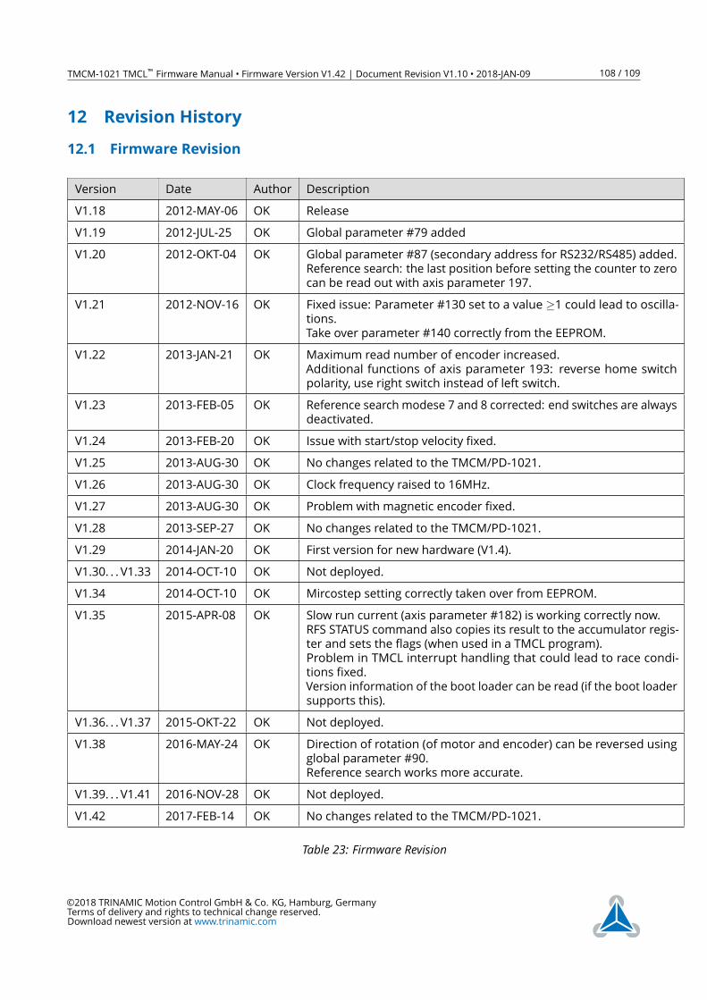
TMCM-1021 TMCL™ Firmware Manual • Firmware Version V1.42 | Document Revision V1.10 • 2018-JAN-09 108 / 109
12 Revision History
12.1 Firmware Revision
Version Date Author Description
V1.18 2012-MAY-06 OK Release
V1.19 2012-JUL-25 OK Global parameter #79 added
V1.20 2012-OKT-04 OK Global parameter #87 (secondary address for RS232/RS485) added.
Reference search: the last position before setting the counter to zero
can be read out with axis parameter 197.
V1.21 2012-NOV-16 OK Fixed issue: Parameter #130 set to a value ≥1 could lead to oscilla-tions.
Take over parameter #140 correctly from the EEPROM.
V1.22 2013-JAN-21 OK Maximum read number of encoder increased.
Additional functions of axis parameter 193: reverse home switch
polarity, use right switch instead of left switch.
V1.23 2013-FEB-05 OK Reference search modese 7 and 8 corrected: end switches are always
deactivated.
V1.24 2013-FEB-20 OK Issue with start/stop velocity fixed.
V1.25 2013-AUG-30 OK No changes related to the TMCM/PD-1021.
V1.26 2013-AUG-30 OK Clock frequency raised to 16MHz.
V1.27 2013-AUG-30 OK Problem with magnetic encoder fixed.
V1.28 2013-SEP-27 OK No changes related to the TMCM/PD-1021.
V1.29 2014-JAN-20 OK First version for new hardware (V1.4).
V1.30. . . V1.33 2014-OCT-10 OK Not deployed.
V1.34 2014-OCT-10 OK Mircostep setting correctly taken over from EEPROM.
V1.35 2015-APR-08 OK Slow run current (axis parameter #182) is working correctly now.
RFS STATUS command also copies its result to the accumulator regis-
ter and sets the flags (when used in a TMCL program).
Problem in TMCL interrupt handling that could lead to race condi-
tions fixed.
Version information of the boot loader can be read (if the boot loader
supports this).
V1.36. . . V1.37 2015-OKT-22 OK Not deployed.
V1.38 2016-MAY-24 OK Direction of rotation (of motor and encoder) can be reversed using
global parameter #90.
Reference search works more accurate.
V1.39. . . V1.41 2016-NOV-28 OK Not deployed.
V1.42 2017-FEB-14 OK No changes related to the TMCM/PD-1021.
Table 23: Firmware Revision
©2018 TRINAMIC Motion Control GmbH & Co. KG, Hamburg, Germany
Terms of delivery and rights to technical change reserved.
Download newest version at www.trinamic.com
TMCM-1021 TMCL™ Firmware Manual • Firmware Version V1.42 | Document Revision V1.10 • 2018-JAN-09 109 / 109
12.2 Document Revision
Version Date Author Description
V1.08 2017-MAR-21 OK Document completely revised.
V1.07 2017-SEP-21 OK Axis parameter #3 corrected.
V1.10 2018-JAN-09 OK Typo in description of axis parameter #204 corrected.
Table 24: Document Revision
©2018 TRINAMIC Motion Control GmbH & Co. KG, Hamburg, Germany
Terms of delivery and rights to technical change reserved.
Download newest version at www.trinamic.com