Embed Size (px)
Citation preview
TMCM-171 module
Hardware Manual
BLDC servo motor controller 20A/48V with RS485 and CAN interface
Trinamic Motion Control GmbH & Co. KG Sternstraße 67
D – 20357 Hamburg, Germany
http://www.trinamic.com
TMCM-171 Manual (V0.92 / Nov 7th, 2007) 2
Copyright © 2007, TRINAMIC Motion Control GmbH & Co. KG
Contents 1 Features ........................................................................................................................................................................... 4 2 Life support policy .......................................................................................................................................................5 3 Electrical Description ...................................................................................................................................................6
3.1 Pinning ...................................................................................................................................................................6 3.1.1 Power supply .............................................................................................................................................6 3.1.2 Motor ............................................................................................................................................................6 3.1.3 CAN and RS485 ..........................................................................................................................................6 3.1.4 Step / Dir .....................................................................................................................................................7 3.1.5 Encoder, Hall, Temperature ....................................................................................................................7 3.1.6 I / O ..............................................................................................................................................................8 3.1.7 Programming connector .........................................................................................................................8
3.2 Jumper “Select Opto In”....................................................................................................................................8 3.3 Application circuit ...............................................................................................................................................9 3.4 Dimensions .........................................................................................................................................................10 3.5 Connectors...........................................................................................................................................................11
4 Operational / Limiting Ratings ...............................................................................................................................12 4.1 Power supply requirements...........................................................................................................................14 4.2 Bus Interface.......................................................................................................................................................14
4.2.1 Terminating the RS485 network.........................................................................................................14 5 Functional description...............................................................................................................................................15
5.1 Setting the basic values for operation (using the demonstration application) .............................15 5.2 Start up for encoder based commutation .................................................................................................15 5.3 Encoder setting ..................................................................................................................................................16 5.4 Hall sensor only operation w/o encoder ...................................................................................................17 5.5 Stop switch .........................................................................................................................................................17 5.6 General Functions (explore using the Windows based demo software) .........................................17 5.7 Temperature, Current and Voltage monitoring functions.....................................................................17 5.8 Programmable motor current limit..............................................................................................................18
6 Revision History ..........................................................................................................................................................19 6.1 Documentation Revision .................................................................................................................................19 6.2 Firmware Revision ............................................................................................................................................19
7 References.....................................................................................................................................................................19
TMCM-171 Manual (V0.92 / Nov 7th, 2007) 3
Copyright © 2007, TRINAMIC Motion Control GmbH & Co. KG
List of Figures Figure 3.1: Pinning of TMCM-171 ......................................................................................................................................6 Figure 3.2: Application circuit ............................................................................................................................................9 Figure 3.3: Circuit board dimensions.............................................................................................................................10 Figure 3.4: Housing dimensions .....................................................................................................................................11
List of Tables Table 1.1: Order codes ......................................................................................................................................................... 4 Table 3.1: Pinning of power supply connector ............................................................................................................6 Table 3.2: Pinning of motor connector...........................................................................................................................6 Table 3.3: Pinning of CAN and RS485 connector .........................................................................................................6 Table 3.4: Pinning of step / dir connector .....................................................................................................................7 Table 3.5: Pinning of Encoder, Hall, Temperature connector ...................................................................................7 Table 3.6: Pinning of I / O connector..............................................................................................................................8 Table 3.7: Programming connector (to be used by Trinamic only)........................................................................8 Table 3.8: Connectors .........................................................................................................................................................11 Table 4.1: Operational ratings..........................................................................................................................................13 Table 5.1: Temperature, Current and Voltage monitoring functions (LEDs) ......................................................17 Table 6.1: Documentation Revisions..............................................................................................................................19 Table 6.2: Firmware Revision...........................................................................................................................................19 Table 7.1: References..........................................................................................................................................................19
TMCM-171 Manual (V0.92 / Nov 7th, 2007) 4
Copyright © 2007, TRINAMIC Motion Control GmbH & Co. KG
1 Features The TMCM-171 is a controller / driver module for high performance servo drives based on brushless DC motors. It gives a high resolution like a stepper motor coupled with the high dynamic, high velocity and high reliability of a BLDC drive. The motors and switches can be connected easily with screw terminals. A build-in ramp generator allows parameterized smooth positioning. The TMCM-171 supports BLDC motors with nearly any number of poles and incremental encoders with nearly any resolution. The TMCM-171 integrates a position regulator and a ramp generator, to allow for velocity modes. The module can be remote controlled via a CAN or RS485 interface. Additionally the TMCM-171 is equipped with a step direction interface. Stand alone operation is also possible. Its integration into the TRINAMIC family of motor control modules makes it easy to choose either a stepper motor or a BLDC motor or any combination for an application. Applications • Replacement of servo drive by high reliability / low cost BLDC drive • Fast and precise positioning • Smooth very low to very high constant / variable velocity drives • Very high velocity stability drives Motor / Encoder type • Sine (or block) commutated BLDC motors with encoder and with / without additional hall sensors • Hall sensor based motors can be operated without encoder • Motor power from a few watts to 800W • Motor velocity up to 100,000 RPM (electrical field) • Incremental encoder (2 channel with option for N-channel) with resolution from 256 to 30000 /
motor rotation (opt. per electrical field rotation) • 12V to 48V nominal motor voltage • RMS motor current up to 20A (sine commutation) Highlights • High-efficiency operation, low power-dissipation • Motor RMS current measurement in sine commutation mode • Very fast response time leads to dynamic motor behavior • CAN interface and RS485 integrated • Step direction interface • Stand alone capability • Typical Supply voltage 14V – 48V • Integrated Protection: Reverse polarity and overload / overtemperature / overvoltage • Supports the TRINAMIC TMCL protocol and the TMCL software environment for parameterizing and
for update • Integrated 1024 entry 10 bit motor sine commutation table • External (stop) switch or encoder N channel can be used for absolute position reference • Different start up modes for automatic commutation calibration
Order code Description
TMCM-171 BLDC servo module
Table 1.1: Order codes
TMCM-171 Manual (V0.92 / Nov 7th, 2007) 5
Copyright © 2007, TRINAMIC Motion Control GmbH & Co. KG
2 Life support policy TRINAMIC Motion Control GmbH & Co. KG does not authorize or warrant any of its products for use in life support systems, without the specific written consent of TRINAMIC Motion Control GmbH & Co. KG. Life support systems are equipment intended to support or sustain life, and whose failure to perform, when properly used in accordance with instructions provided, can be reasonably expected to result in personal injury or death. © TRINAMIC Motion Control GmbH & Co. KG 2007 Information given in this data sheet is believed to be accurate and reliable. However no responsibility is assumed for the consequences of its use nor for any infringement of patents or other rights of third parties, which may result form its use. Specifications subject to change without notice.
TMCM-171 Manual (V0.92 / Nov 7th, 2007) 6
Copyright © 2007, TRINAMIC Motion Control GmbH & Co. KG
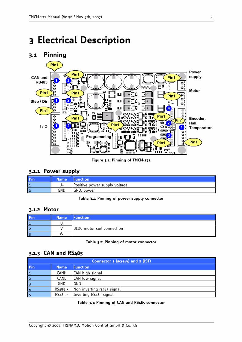
3 Electrical Description 3.1 Pinning
CAN andRS485
Step / Dir
I / O
Powersupply
Motor
Encoder,Hall,Temperature
Pin1
Pin1
Pin1Pin1
Pin1
Pin1
Pin1
Pin1
Pin1
Pin1
Pin1
Pin1
1 2
1
1
2
2
4
21
3
Pin1
Programming
Figure 3.1: Pinning of TMCM-171
3.1.1 Power supply Pin Name Function 1 U+ Positive power supply voltage 2 GND GND, power
Table 3.1: Pinning of power supply connector
3.1.2 Motor Pin Name Function 1 U 2 V 3 W
BLDC motor coil connection
Table 3.2: Pinning of motor connector
3.1.3 CAN and RS485 Connector 1 (screw) and 2 (JST)
Pin Name Function 1 CANH CAN high signal 2 CANL CAN low signal 3 GND GND 4 RS485 + Non inverting rs485 signal 5 RS485 - Inverting RS485 signal
Table 3.3: Pinning of CAN and RS485 connector
TMCM-171 Manual (V0.92 / Nov 7th, 2007) 7
Copyright © 2007, TRINAMIC Motion Control GmbH & Co. KG
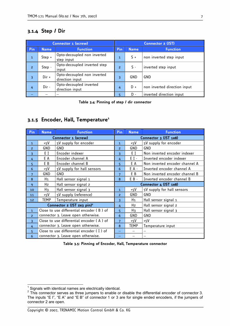
3.1.4 Step / Dir
Connector 1 (screw) Connector 2 (JST)
Pin Name Function Pin Name Function
1 Step + Opto-decoupled non inverted step input
1 S + non inverted step input
2 Step - Opto-decoupled inverted step input
2 S - inverted step input
3 Dir + Opto-decoupled non inverted direction input
3 GND GND
4 Dir - Opto-decoupled inverted direction input
4 D + non inverted direction input
-- -- -- 5 D - inverted direction input
Table 3.4: Pinning of step / dir connector
3.1.5 Encoder, Hall, Temperature1
Pin Name Function Pin Name Function
Connector 1 (screw) Connector 3 (JST 1x8) 1 +5V 5V supply for encoder 1 +5V 5V supply for encoder 2 GND GND 2 GND GND 3 E I Encoder indexer 3 E I Non inverted encoder indexer 4 E A Encoder channel A 4 E I - Inverted encoder indexer 5 E B Encoder channel B 5 E A Non inverted encoder channel A 6 +5V 5V supply for hall sensors 6 E A - Inverted encoder channel A 7 GND GND 7 E B Non inverted encoder channel B 8 H1 Hall sensor signal 1 8 E B - Inverted encoder channel B 9 H2 Hall sensor signal 2 Connector 4 (JST 1x8) 10 H3 Hall sensor signal 3 1 +5V 5V supply for hall sensors 11 +5V 5V supply (reference) 2 GND GND 12 TEMP Temperature input 3 H1 Hall sensor signal 1
Connector 2 (JST 2x3 pin)2 4 H2 Hall sensor signal 2 1 5 H3 Hall sensor signal 3 2
Close to use differential encoder ( B ) of connector 3. Leave open otherwise. 6 GND GND
3 7 +5V +5V 4
Close to use differential encoder ( A ) of connector 3. Leave open otherwise. 8 TEMP Temperature input
5 -- -- -- 6
Close to use differential encoder ( I ) of connector 3. Leave open otherwise. -- -- --
Table 3.5: Pinning of Encoder, Hall, Temperature connector
1 Signals with identical names are electrically identical. 2 This connector serves as three jumpers to enable or disable the differential encoder of connector 3. The inputs “E I”, “E A” and “E B” of connector 1 or 3 are for single ended encoders, if the jumpers of connector 2 are open.
TMCM-171 Manual (V0.92 / Nov 7th, 2007) 8
Copyright © 2007, TRINAMIC Motion Control GmbH & Co. KG
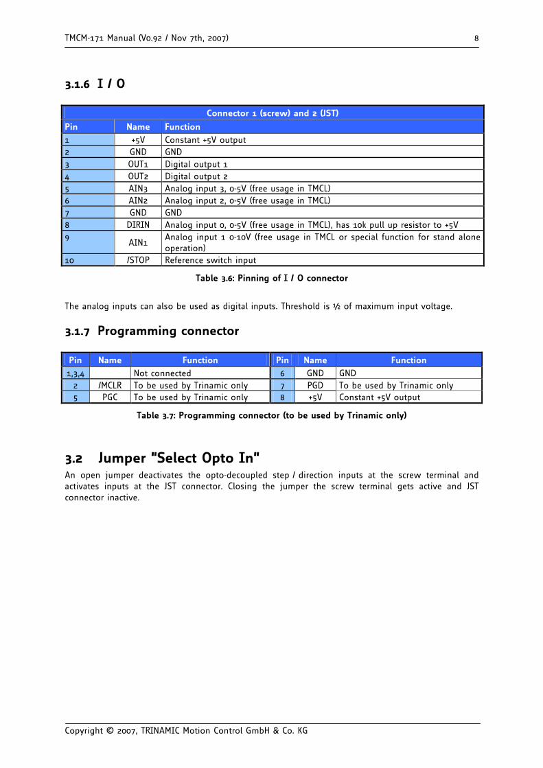
3.1.6 I / O
Connector 1 (screw) and 2 (JST)
Pin Name Function 1 +5V Constant +5V output 2 GND GND 3 OUT1 Digital output 1 4 OUT2 Digital output 2 5 AIN3 Analog input 3, 0-5V (free usage in TMCL) 6 AIN2 Analog input 2, 0-5V (free usage in TMCL) 7 GND GND 8 DIRIN Analog input 0, 0-5V (free usage in TMCL), has 10k pull up resistor to +5V 9
AIN1 Analog input 1 0-10V (free usage in TMCL or special function for stand alone operation)
10 /STOP Reference switch input
Table 3.6: Pinning of I / O connector
The analog inputs can also be used as digital inputs. Threshold is ½ of maximum input voltage.
3.1.7 Programming connector
Pin Name Function Pin Name Function 1,3,4 Not connected 6 GND GND
2 /MCLR To be used by Trinamic only 7 PGD To be used by Trinamic only 5 PGC To be used by Trinamic only 8 +5V Constant +5V output
Table 3.7: Programming connector (to be used by Trinamic only)
3.2 Jumper “Select Opto In” An open jumper deactivates the opto-decoupled step / direction inputs at the screw terminal and activates inputs at the JST connector. Closing the jumper the screw terminal gets active and JST connector inactive.
TMCM-171 Manual (V0.92 / Nov 7th, 2007) 9
Copyright © 2007, TRINAMIC Motion Control GmbH & Co. KG
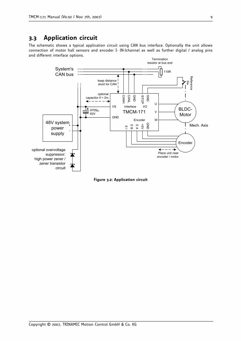
3.3 Application circuit The schematic shows a typical application circuit using CAN bus interface. Optionally the unit allows connection of motor hall sensors and encoder I- (N-)channel as well as further digital / analog pins and different interface options.
TMCM-171
Reference
Sw.
BLDC-Motor
Encoder
Mech. Axis
GN
D
/STO
P
GN
DI/OInterface
CA
NL
CA
NH
System'sCAN bus
keep distanceshort for CAN
110R
Terminationresistor at bus end
U
V
WGN
D
Encoder
+5V
E A
E B
VS
GND
Place unit nearencoder / motor
4700µ,63V
48V systempowersupply
optional overvoltagesuppressor:
high power zener /zener transistor
circuit
+
-
optionalcapacitor if > 2m
E I
Figure 3.2: Application circuit
TMCM-171 Manual (V0.92 / Nov 7th, 2007) 10
Copyright © 2007, TRINAMIC Motion Control GmbH & Co. KG
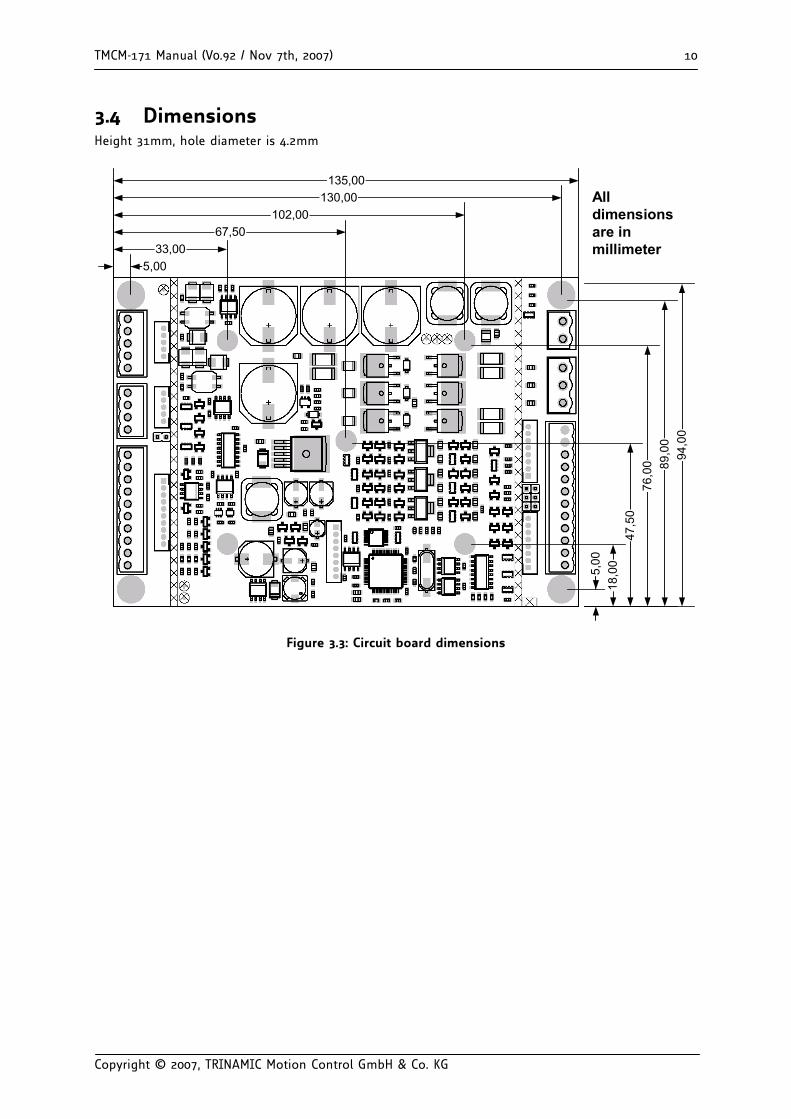
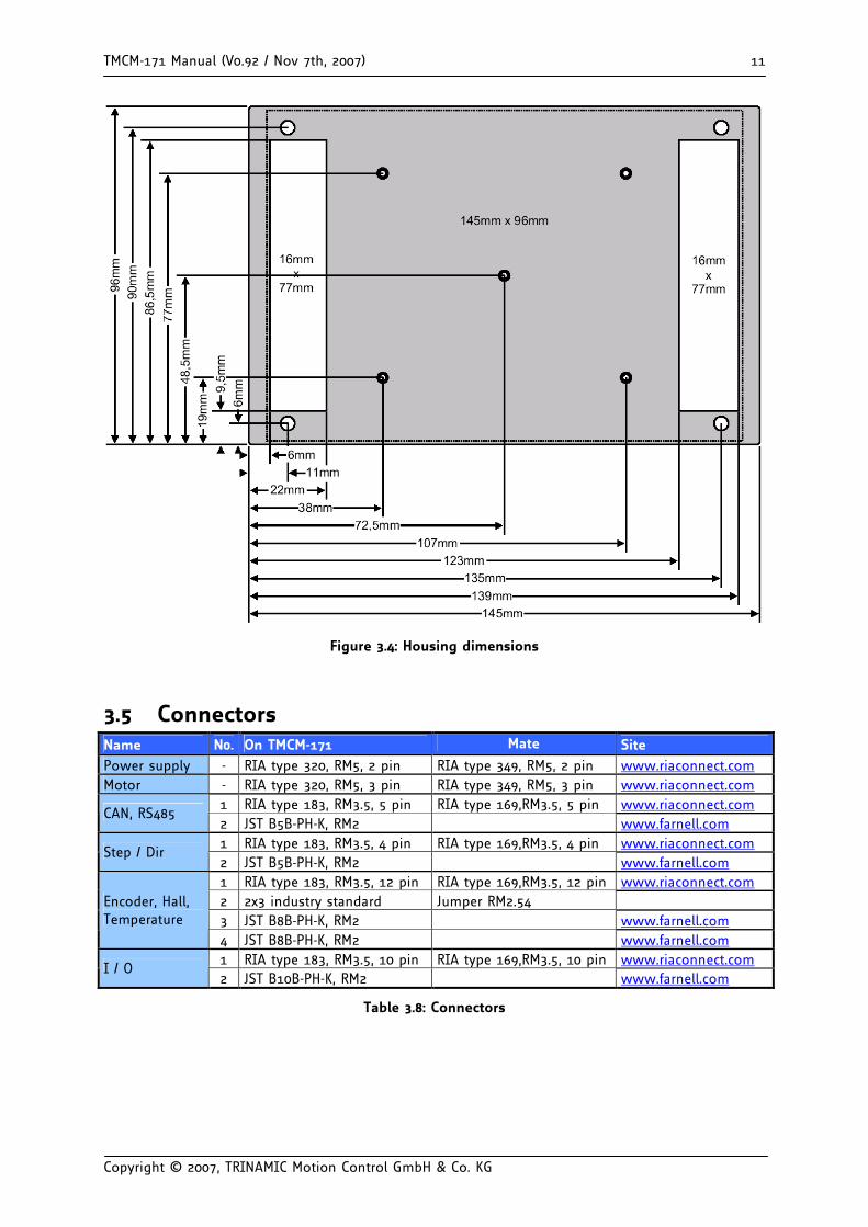
3.4 Dimensions Height 31mm, hole diameter is 4.2mm
135,00
94,0
0
5,00
89,0
076
,00
47,5
018
,00
5,0033,00
67,50102,00
130,00 Alldimensionsare inmillimeter
Figure 3.3: Circuit board dimensions
TMCM-171 Manual (V0.92 / Nov 7th, 2007) 11
Copyright © 2007, TRINAMIC Motion Control GmbH & Co. KG
Figure 3.4: Housing dimensions
3.5 Connectors Name N0. On TMCM-171 Mate Site Power supply - RIA type 320, RM5, 2 pin RIA type 349, RM5, 2 pin www.riaconnect.com Motor - RIA type 320, RM5, 3 pin RIA type 349, RM5, 3 pin www.riaconnect.com
1 RIA type 183, RM3.5, 5 pin RIA type 169,RM3.5, 5 pin www.riaconnect.com CAN, RS485
2 JST B5B-PH-K, RM2 www.farnell.com 1 RIA type 183, RM3.5, 4 pin RIA type 169,RM3.5, 4 pin www.riaconnect.com
Step / Dir 2 JST B5B-PH-K, RM2 www.farnell.com 1 RIA type 183, RM3.5, 12 pin RIA type 169,RM3.5, 12 pin www.riaconnect.com 2 2x3 industry standard Jumper RM2.54 3 JST B8B-PH-K, RM2 www.farnell.com
Encoder, Hall, Temperature
4 JST B8B-PH-K, RM2 www.farnell.com 1 RIA type 183, RM3.5, 10 pin RIA type 169,RM3.5, 10 pin www.riaconnect.com
I / O 2 JST B10B-PH-K, RM2 www.farnell.com
Table 3.8: Connectors
TMCM-171 Manual (V0.92 / Nov 7th, 2007) 12
Copyright © 2007, TRINAMIC Motion Control GmbH & Co. KG
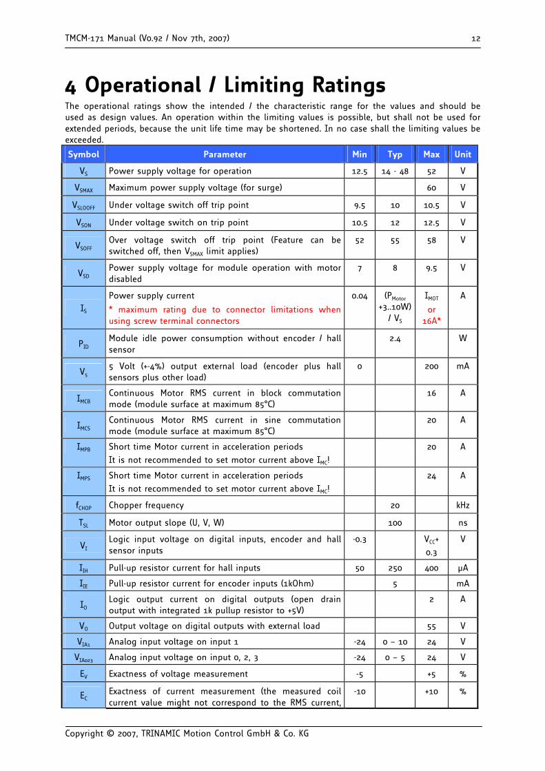
4 Operational / Limiting Ratings The operational ratings show the intended / the characteristic range for the values and should be used as design values. An operation within the limiting values is possible, but shall not be used for extended periods, because the unit life time may be shortened. In no case shall the limiting values be exceeded.
Symbol Parameter Min Typ Max Unit
VS Power supply voltage for operation 12.5 14 - 48 52 V
VSMAX Maximum power supply voltage (for surge) 60 V
VSLOOFF Under voltage switch off trip point 9.5 10 10.5 V
VSON Under voltage switch on trip point 10.5 12 12.5 V
VSOFF Over voltage switch off trip point (Feature can be switched off, then VSMAX limit applies)
52 55 58 V
VSD Power supply voltage for module operation with motor disabled
7 8 9.5 V
IS Power supply current
* maximum rating due to connector limitations when using screw terminal connectors
0.04 (PMotor +3..10W)
/ VS
IMOT
or 16A*
A
PID Module idle power consumption without encoder / hall sensor
2.4 W
V5 5 Volt (+-4%) output external load (encoder plus hall sensors plus other load)
0 200 mA
IMCB Continuous Motor RMS current in block commutation mode (module surface at maximum 85°C)
16 A
IMCS Continuous Motor RMS current in sine commutation mode (module surface at maximum 85°C)
20 A
IMPB Short time Motor current in acceleration periods
It is not recommended to set motor current above IMC!
20 A
IMPS Short time Motor current in acceleration periods
It is not recommended to set motor current above IMC!
24 A
fCHOP Chopper frequency 20 kHz
TSL Motor output slope (U, V, W) 100 ns
VI Logic input voltage on digital inputs, encoder and hall sensor inputs
-0.3 VCC+
0.3
V
IIH Pull-up resistor current for hall inputs 50 250 400 µA
IIE Pull-up resistor current for encoder inputs (1kOhm) 5 mA
IO Logic output current on digital outputs (open drain output with integrated 1k pullup resistor to +5V)
2 A
VO Output voltage on digital outputs with external load 55 V
VIA1 Analog input voltage on input 1 -24 0 – 10 24 V
VIA023 Analog input voltage on input 0, 2, 3 -24 0 – 5 24 V
EV Exactness of voltage measurement -5 +5 %
EC Exactness of current measurement (the measured coil current value might not correspond to the RMS current,
-10 +10 %
TMCM-171 Manual (V0.92 / Nov 7th, 2007) 13
Copyright © 2007, TRINAMIC Motion Control GmbH & Co. KG
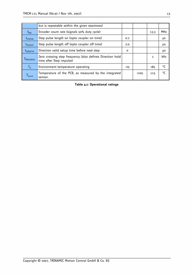
but is repeatable within the given exactness)
fENC Encoder count rate (signals 50% duty cycle) 13.3 MHz
tSTEPON Step pulse length on (opto coupler on time) 0.7 µs
tSTEPOFF Step pulse length off (opto coupler off time) 2.0 µs
tDIRSETUP Direction valid setup time before next step 0 µs
fZEROCROSS Zero crossing step frequency (also defines Direction hold time after Step impulse)
1 kHz
TO Environment temperature operating -25 +85 °C
Tboard Temperature of the PCB, as measured by the integrated sensor.
<105 115 °C
Table 4.1: Operational ratings
TMCM-171 Manual (V0.92 / Nov 7th, 2007) 14
Copyright © 2007, TRINAMIC Motion Control GmbH & Co. KG
4.1 Power supply requirements The power supply should be designed in a way, that it supplies the nominal motor voltage at the desired maximum motor power. In no case shall the supply value exceed the upper / lower voltage limit. The BLDC motor unit uses a chopper principle, i.e. the power supply to the motor is pulsed at a frequency of 20kHz. To ensure reliable operation of the unit, the power supply has to have a sufficient output capacitor and the supply cables should have a low resistance, so that the chopper operation does not lead to an increased power supply ripple directly at the unit. Power supply ripple due to the chopper operation should be kept at a maximum of a few 100mV. Therefore we recommend to
a) keep power supply cables as short as possible b) use large diameter for power supply cables c) if the distance to the power supply is large (i.e. more than 2-3m), use a robust 4700µF or
larger additional filtering capacitor located near to the motor driver unit. An effect the power supply has to cope with, is, that the motor can feed back substantial current into the power supply whenever it is actively braked! While this generally is a positive effect (because it saves energy), precautions have to be taken, to limit the supply voltage to within the operational limits. The TMCM-171 contains an overvoltage protection circuit, which disables braking whenever the upper supply voltage limit is exceeded. This automatic function may lead to an unwanted behavior, i.e. overshooting the target position, and thus can be disabled. Disabling the overvoltage protection should only be done, provided that the user takes additional precautions to limit the voltage: It is recommended to use
a) a large capacitor on the power supply lines able to store substantial part of feed back energy b) a zener / suppressor diode circuitry, limiting the power supply voltage to a maximum of 52-
60V
4.2 Bus Interface The TMCM-171 can be operated via CAN or RS485 in the same way. CAN bus and RS485 require a termination resistor at both ends of the cable (but not at every unit).
4.2.1 Terminating the RS485 network For RS485 in addition to the termination resistor a termination network is required, which forces an “inactive” level to the line, when no driver is on. Typically, use a 1K resistor to + 5V for RS485+ line and a 1K resistor to GND for the RS485- line at some point of the network.
TMCM-171 Manual (V0.92 / Nov 7th, 2007) 15
Copyright © 2007, TRINAMIC Motion Control GmbH & Co. KG
5 Functional description 5.1 Setting the basic values for operation (using the
demonstration application) The TMCM-171 can use nearly any BLDC motor and encoder type. However, care has to be taken to correctly set the motor pole count (default: 8) and encoder resolution (default: 4096) and direction (default: Encoder gives same direction as motor) before trying to operate the motor! If a hall sensor is used, please check if the hall sensor polarity is to be reversed (try operating the motor in block commutation mode, first). Also choose a fitting initialization mode (2 is most universal) and set the corresponding parameters (please see chapter on start up). The motor behavior afterwards may still give unsatisfactory results: The next step is to tune the PID parameters. For these basic settings, the Windows based demonstration application can be used. It requires connection to the CAN or the RS485 interface. As a first step use the TMCL-IDE to set the parameter “Telegram pause time” to a value of about 20. Further basic settings are required for motor start up (see next chapter). Hint: To avoid motor operation or damage, before the unit is completely parameterized, use a
supply voltage of only 8V! This disables the motor.
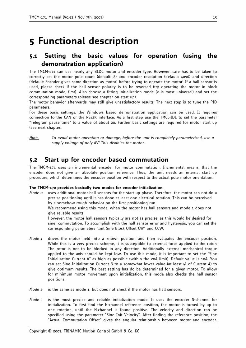
5.2 Start up for encoder based commutation The TMCM-171 uses an incremental encoder for motor commutation. Incremental means, that the encoder does not give an absolute position reference. Thus, the unit needs an internal start up procedure, which determines the encoder position with respect to the actual pole motor orientation. The TMCM-170 provides basically two modes for encoder initialization: Mode 0 uses additional motor hall sensors for the start up phase. Therefore, the motor can not do a
precise positioning until it has done at least one electrical rotation. This can be perceived by a somehow rough behavior on the first positioning run. We recommend using this mode, when the motor has hall sensors and mode 1 does not give reliable results. However, the motor hall sensors typically are not as precise, as this would be desired for sine commutation. To accomplish with the hall sensor error and hysteresis, you can set the corresponding parameters “Init Sine Block Offset CW” and CCW.
Mode 1 drives the motor field into a known position and then evaluates the encoder position.
While this is a very precise scheme, it is susceptible to external force applied to the rotor: The rotor is not to be blocked in any direction. Additionally external mechanical torque applied to the axis should be kept low. To use this mode, it is important to set the “Sine Initialization Current A” as high as possible (within the 20A limit). Default value is 10A. You can set Sine Initialization Current B to a somewhat lower value (at least ½ of Current A) to give optimum results. The best setting has do be determined for a given motor. To allow for minimum motor movement upon initialization, this mode also checks the hall sensor positions.
Mode 2 is the same as mode 1, but does not check if the motor has hall sensors. Mode 3 is the most precise and reliable initialization mode: It uses the encoder N-channel for
initialization. To first find the N-channel reference position, the motor is turned by up to one rotation, until the N-channel is found positive. The velocity and direction can be specified using the parameter “Sine Init Velocity”. After finding the reference position, the “Actual Commutation Offset” gives the angular relationship between motor and encoder.
TMCM-171 Manual (V0.92 / Nov 7th, 2007) 16
Copyright © 2007, TRINAMIC Motion Control GmbH & Co. KG
Therefore this parameter has to be stored correctly in EEPROM before power on! Do not enable this mode, before the parameter has been set correctly. Mode 4 helps for the very first initialization of this mode.
Mode 4 helps to do a first initialization and tuning of mode 3. It searches for the N-channel
reference point first, and then does a mode 2 initialization to determine the correct setting for the “Actual Commutation Offset”. The encoder N-channel polarity has to be high active for this mode (the actual setting of the encoder null polarity has no influence in this mode), and, additionally, you have to specify the polarity of the encoder A- and B-channel upon N-channel activity using the setting “Encoder Null Polarity”, bits 1 and 2. The correct setting of this depends on the encoder. If the N-channel referencing fails, the motor does two full rotations and then stops. Try again with reversing the “Encoder Null Polarity”. After successfully initializing the “Actual Commutation Offset”, you can try moving the motor and tune the offset, if desired. Then store the offset and switch to mode 3. If any encoder errors are flagged during operation of the motor, retry with a modified setting for A- and B-channel polarity.
Attention: Initialization modes 1 to 4 apply a high current to the motor for a few seconds. Be sure
to parameterize the initialization current correctly (i.e. not more than 2* the maximum rated motor current) before first powering on the unit.
The quality of the initialization phase result can be checked by rotating the motor left and right at the maximum velocity (use a velocity setting slightly higher than the motor can follow). Maximum velocity for left and right direction shall not differ by more than a few percent. Also make some checks if results are reproducible. Whenever changing one of these parameters, re-power the unit to restart initialization phase!
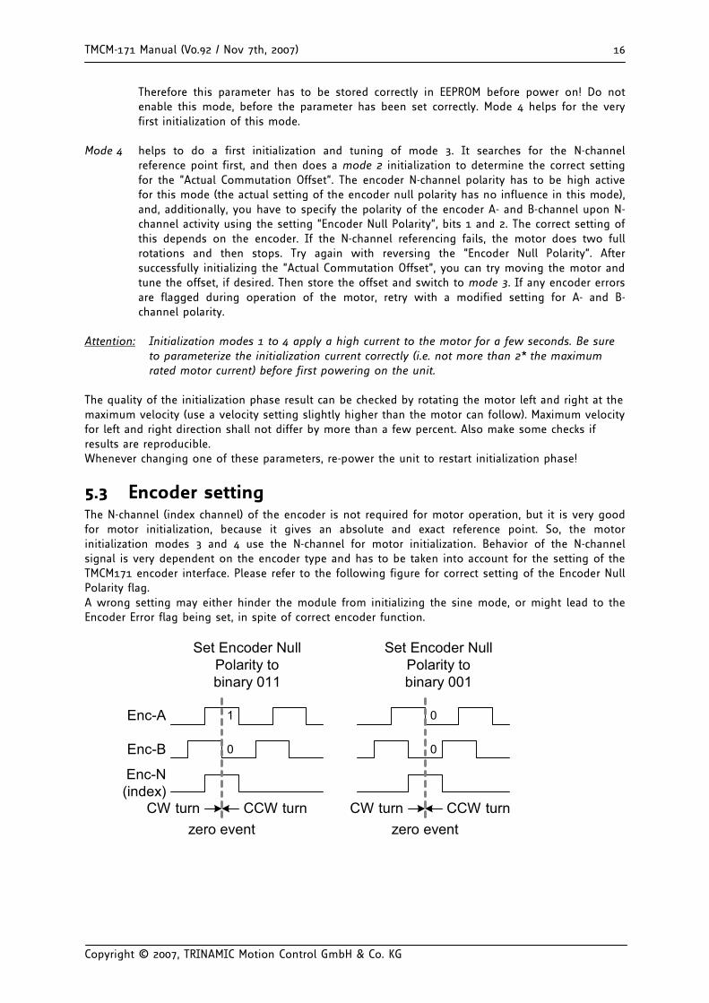
5.3 Encoder setting The N-channel (index channel) of the encoder is not required for motor operation, but it is very good for motor initialization, because it gives an absolute and exact reference point. So, the motor initialization modes 3 and 4 use the N-channel for motor initialization. Behavior of the N-channel signal is very dependent on the encoder type and has to be taken into account for the setting of the TMCM171 encoder interface. Please refer to the following figure for correct setting of the Encoder Null Polarity flag. A wrong setting may either hinder the module from initializing the sine mode, or might lead to the Encoder Error flag being set, in spite of correct encoder function.
zero event
Enc-A
Enc-B
Enc-N(index)
Set Encoder NullPolarity tobinary 011
Set Encoder NullPolarity tobinary 001
zero eventCW turn CCW turn CW turn CCW turn
0
1 0
0
TMCM-171 Manual (V0.92 / Nov 7th, 2007) 17
Copyright © 2007, TRINAMIC Motion Control GmbH & Co. KG
5.4 Hall sensor only operation w/o encoder The module can be used without an encoder. In this case, set the encoder resolution parameter (SGP 250) to the hall sensor resolution, i.e. 3 times the number of motor poles. Example: For a 4 pole motor set the encoder resolution to 12. To avoid oscillations in positioning mode, the algorithm in this mode stops regulation, as soon as the target distance is below the setting as determined by “MVP target reached distance”. Adapt this setting to your needs. Switch the module to hall sensor based commutation permanently in order to skip encoder initialization procedure in this configuration. Please be aware, that the hall sensor resolution is very low, when compared to an encoder, and thus, the PID regulator parameterization values have to be set much higher than the default setting. Without encoder, the velocity measurement is not available. You may want to set a lower value than the default for the “PWM Hysteresis” setting to get a softer response upon target reaching.
5.5 Stop switch For positioning applications, typically some kind of global initialization is required. This can either be done via a central unit operating the motor via its bus interface, or a reference switch can be connected to the stop input (pull down to 0V at reference point). The position counter can be automatically cleared when this point is reached. Be careful not to apply a voltage different from GND to this digital input!
5.6 General Functions (explore using the Windows based demo software)
The TMCM-171 module can either be remote controlled via the PC demonstration software or a user specific program. The function of the stand alone mode can be modified by the user by writing initialization values to the on-board EEPROM, e.g. a maximum rotation velocity, motor current limit and rotation direction. For more detailed software information refer to the TMCM-170 Module – Reference and Programming Manual (see 7: References).
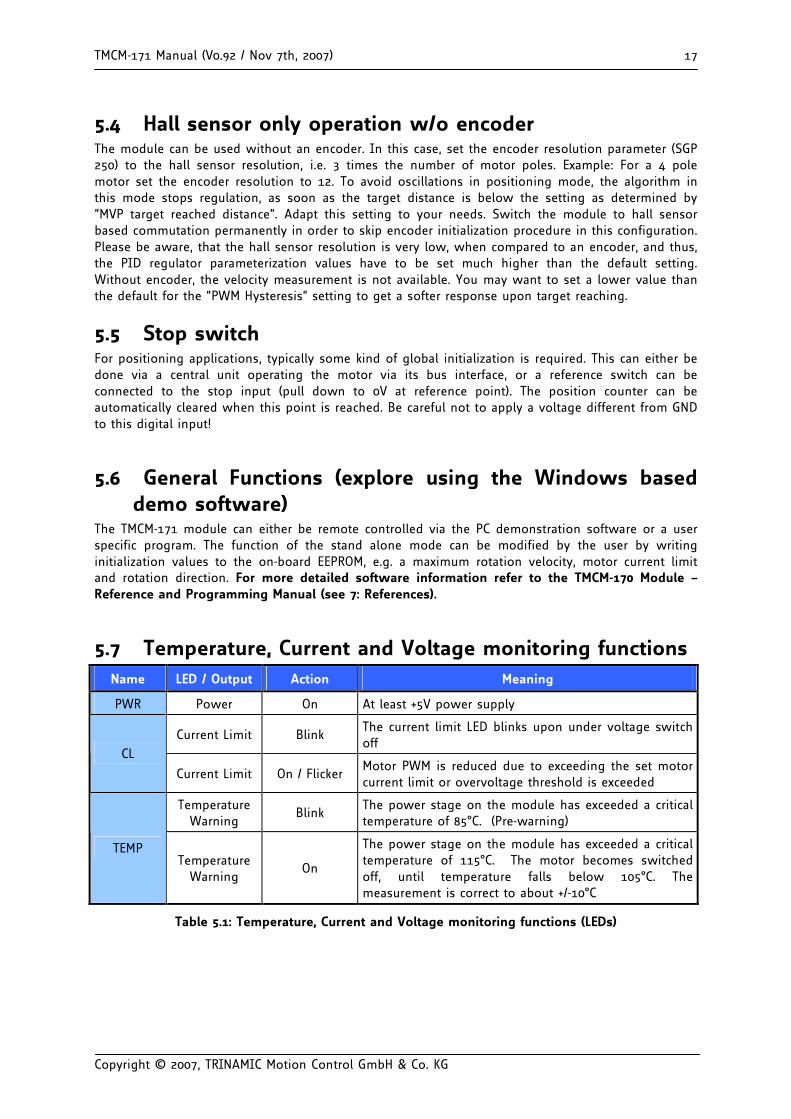
5.7 Temperature, Current and Voltage monitoring functions Name LED / Output Action Meaning
PWR Power On At least +5V power supply
Current Limit Blink The current limit LED blinks upon under voltage switch off
CL
Current Limit On / Flicker Motor PWM is reduced due to exceeding the set motor current limit or overvoltage threshold is exceeded
Temperature Warning
Blink The power stage on the module has exceeded a critical temperature of 85°C. (Pre-warning)
TEMP Temperature
Warning On
The power stage on the module has exceeded a critical temperature of 115°C. The motor becomes switched off, until temperature falls below 105°C. The measurement is correct to about +/-10°C
Table 5.1: Temperature, Current and Voltage monitoring functions (LEDs)
TMCM-171 Manual (V0.92 / Nov 7th, 2007) 18
Copyright © 2007, TRINAMIC Motion Control GmbH & Co. KG
5.8 Programmable motor current limit The motor current limiting function is meant as a function for torque limiting, and for protection of motor, power supply and mechanical load.
Whenever the pre-programmed motor current is exceeded in a chopper cycle, the TMCM-171 calculates a reduced PWM value for the next chopper cycle. New values are calculated 1000 times a second. The response time of the current regulation can be set using the parameter “current regulation loop delay”:
A value of zero means, that in every 1kHz period, the current correction calculation is directly executed and the resulting PWM value is taken. A higher current loop delay acts like a filter for the current. The higher the delay value, the slower the current loop response time. A value of 10 (default) leads to a current regulation response time of about 10 ms for an 1/e response. On the mechanical side, a higher value simulates a higher dynamic mass of the motor.
The actual current regulation time may differ, depending on the PID settings.
Attention: Please be careful, when programming a high value into the current regulation loop delay register: The motor current could reach a very high peak value upon mechanical blocking of the motor. The same goes for the motor current limit value: do not set higher than 16A if you are not sure about this. Please remark, that the current measurement gives different results in block and in sine commutation mode, due to the different driving scheme.
The unit has a short circuit protection circuit, which limits coil current to about 40A. However, this function should not be relied on in normal operating conditions.
There is a number of aspects when using the current limiting function:
• The current measurement is done at a point of the chopper cycle, where just one coil is switched on. When using sine commutation, the effective motor current is calculated from a measurement of all three coils.
• The current measurement can not detect currents below about 200-300mA. If the current limit is set to a too low value, the motor may operate spuriously or become continuously switched off.
• The current limiting function is not meant as a protection against a hard short circuit.
• The performance of the current limiting depends on the motor and on the commutation mode. The current limit should be programmed to a value high enough, in order to achieve good positioning and acceleration performance.
• Operation of the current limiter and the PID regulator may result in instable behavior, if the motor gets into a resonance area. Try adapting the current regulation loop delay parameter.
• If the motor is blocked and the ramp generator is not stopped, the motor will speed up and try to catch up with the ramp generator position after removal of the blocking. To control this effect, you can set the parameter “Clear Target Distance” in order to stop the ramp generator, when the deviation between the positions become to large. The effect of this may look somehow weird if the user does not expect it.
Please refer to the programming manual for the required current settings.
TMCM-171 Manual (V0.92 / Nov 7th, 2007) 19
Copyright © 2007, TRINAMIC Motion Control GmbH & Co. KG
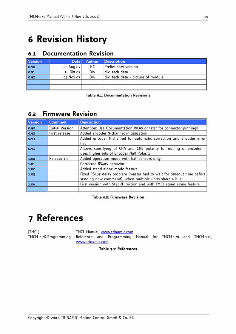
6 Revision History 6.1 Documentation Revision Version Date Author Description 0.90 22-Aug-07 HC Preliminary version 0.91 18-Okt-07 Dw div. tech data 0.92 07-Nov-07 Dw div. tech data + picture of module
Table 6.1: Documentation Revisions
6.2 Firmware Revision Version Comment Description
0.90 Initial Version Attention: Use Documentation V0.90 or later for connector pinning!!! 0.92 First release Added encoder N-channel initialization 0.93 Added encoder N-channel for automatic correction and encoder error
flag 0.94 Allows specifying of CHA and CHB polarity for nulling of encoder –
uses higher bits of Encoder Null Polarity 1.00 Release 1.0 Added operation mode with hall sensors only. 1.01 Corrected RS485 behavior 1.02 Added stand alone mode feature 1.03 Fixed RS485 delay problem (master had to wait for timeout time before
sending new command), when multiple units share a bus 1.06 First version with Step-/Direction and with TMCL stand alone feature
Table 6.2: Firmware Revision
7 References [TMCL] TMCL Manual, www.trinamic.com TMCM–17X Programming Reference and Programming Manual for TMCM-170 and TMCM-171,
www.trinamic.com
Table 7.1: References