Embed Size (px)
Citation preview
Module for Stepper Motors MODULE
TMCM-1111 Hardware ManualHardware Version V1.00 | Document Revision V0.90 • 2017-July-11The TMCM-1111 stepRocker servo is a single axis motor controller/driver board for 2-phase bipolar steppermotors. It supports S-shaped ramps in addition to linear ramps and closed-loop operation together withan external encoder.
Features• Single axis controller/driver for 2-phase bipolar stepper motor
• S-shaped ramps + linear ramps• Closed-loop operation with exter-nal encoder
• +10. . . 30V DC supply voltage• Up to 2.8A RMS motor current• RS485 & USB interface• multi-purpose inputs and outputs
Applications• Life Sciences • Test & Measurement • Robotics / Automation
Simplified Block Diagram
10… 30V DC
µC
EEPROM
USB
Inputs
MotionController
GPIOs
RS485
Step/Dir IN
Motor 0
STOP_L, STOP_R,HOME
Driver
TMCM-1111_V10
E
OptionalEncoder forclosed-Loop
ABN
©2017 TRINAMIC Motion Control GmbH & Co. KG, Hamburg, GermanyTerms of delivery and rights to technical change reserved.Download newest version at: www.trinamic.com
Read entire documentation.
TMCM-1111 Hardware Manual • Hardware Version V1.00 | Document Revision V0.90 • 2017-July-11 2 / 25
Contents1 Features 32 Order Codes 43 Mechanical and Electrical Interfacing 53.1 Size of board . . . . . . . . . . . . . . . . . . . . . . . . . . . . . . . . . . . . . . . . . . . . . . . . 5
4 Connectors 64.1 Power Connector . . . . . . . . . . . . . . . . . . . . . . . . . . . . . . . . . . . . . . . . . . . . . 84.2 I/O Connector (Microcontroller) . . . . . . . . . . . . . . . . . . . . . . . . . . . . . . . . . . . . . 84.3 Motor Connector . . . . . . . . . . . . . . . . . . . . . . . . . . . . . . . . . . . . . . . . . . . . . 94.4 STOP_L, STOP_R and HOME Switch Connector . . . . . . . . . . . . . . . . . . . . . . . . . . . . 94.5 RS485 and CAN Connector . . . . . . . . . . . . . . . . . . . . . . . . . . . . . . . . . . . . . . . 9
4.5.1 Upgrade the stepRocker for CAN communication . . . . . . . . . . . . . . . . . . . . . . 104.6 USB Connector . . . . . . . . . . . . . . . . . . . . . . . . . . . . . . . . . . . . . . . . . . . . . . 104.7 Step/Dir Input Connector . . . . . . . . . . . . . . . . . . . . . . . . . . . . . . . . . . . . . . . . 114.8 Step/Dir Output Connector . . . . . . . . . . . . . . . . . . . . . . . . . . . . . . . . . . . . . . . 114.9 +5V Out Connector . . . . . . . . . . . . . . . . . . . . . . . . . . . . . . . . . . . . . . . . . . . . 114.10 Microcontroller Programming Interface . . . . . . . . . . . . . . . . . . . . . . . . . . . . . . . . 12
5 Jumper Settings 136 LEDs 147 Communication 157.1 RS485 . . . . . . . . . . . . . . . . . . . . . . . . . . . . . . . . . . . . . . . . . . . . . . . . . . . . 157.2 USB . . . . . . . . . . . . . . . . . . . . . . . . . . . . . . . . . . . . . . . . . . . . . . . . . . . . . 167.3 CAN (Retro-fit Option) . . . . . . . . . . . . . . . . . . . . . . . . . . . . . . . . . . . . . . . . . . 16
8 Functional Description 189 Operational Ratings and Characteristics 1910 Abbreviations used in this Manual 2011 Figures Index 2112 Tables Index 2213 Supplemental Directives 2313.1 Producer Information . . . . . . . . . . . . . . . . . . . . . . . . . . . . . . . . . . . . . . . . . . 2313.2 Copyright . . . . . . . . . . . . . . . . . . . . . . . . . . . . . . . . . . . . . . . . . . . . . . . . . . 2313.3 Trademark Designations and Symbols . . . . . . . . . . . . . . . . . . . . . . . . . . . . . . . . . 2313.4 Target User . . . . . . . . . . . . . . . . . . . . . . . . . . . . . . . . . . . . . . . . . . . . . . . . . 2313.5 Disclaimer: Life Support Systems . . . . . . . . . . . . . . . . . . . . . . . . . . . . . . . . . . . . 2313.6 Disclaimer: Intended Use . . . . . . . . . . . . . . . . . . . . . . . . . . . . . . . . . . . . . . . . 2313.7 Collateral Documents & Tools . . . . . . . . . . . . . . . . . . . . . . . . . . . . . . . . . . . . . . 24
14 Revision History 2514.1 Hardware Revision . . . . . . . . . . . . . . . . . . . . . . . . . . . . . . . . . . . . . . . . . . . . 2514.2 Document Revision . . . . . . . . . . . . . . . . . . . . . . . . . . . . . . . . . . . . . . . . . . . . 25
©2017 TRINAMIC Motion Control GmbH & Co. KG, Hamburg, GermanyTerms of delivery and rights to technical change reserved.Download newest version at www.trinamic.comRead entire documentation.
TMCM-1111 Hardware Manual • Hardware Version V1.00 | Document Revision V0.90 • 2017-July-11 3 / 25
1 FeaturesThe TMCM-1111 stepRocker servo is a single axis motor controller/driver board for 2-phase bipolar steppermotors. It supports S-shaped ramps in addition to linear ramps and closed-loop operation together withan external encoder.Applications
• Highly compact single axis stepper motor controller/driver board for 2-phase bipolar stepper motors• Linear and S-shaped ramps• Closed-loop operation together with external encoder
Electrical data• Supply voltage: +24V DC (+10. . . +30V DC)• Motor current: up to 1A RMS or 2.8A RMS (can be selected with jumpers)
Mechanical data• Board size: 85mm x 55mm, height 15mmmax. without mating connectors• 4 mounting holes for M3 screws
Interfaces• RS485 host interface• USB 2.0 host interface (mini-USB connector)• Step/Dir input (TTL level)• Step/Dir output (+5V TTL level) for synchronisation (master-slave axes)• 3 multi-purpose inputs (can be used for incremental ABN-encoder)• STOP_L, STOP_R and HOME switch inputs• START input / output for synchronized motion with several axes• 6 multi-purpose I/Os• 2 open-drain outputs• µC programming interface SWD (single wire debug / pads on PCB)• Retro-fit option: CAN 2.0B communication interface
Features• TMC4361 stepper motor controller IC for on-the-fly alteration of many motion specific parameters,linear and S-shaped ramp and closed-loop support
• TMC262 advanced stepper motor driver IC with stallGuard2™ and coolStep™ features. Using thespreadCycle chopper the µ step current sine wave is well formed with smooth zero crossing.
• support for left and right STOP and HOME switches• EEPROM
Software• TMCL™ remote (direct mode) and standalone operation (memory for up to 1024 TMCL™ commands)• Fully supported by TMCL-IDE (PC based integrated development environment)
©2017 TRINAMIC Motion Control GmbH & Co. KG, Hamburg, GermanyTerms of delivery and rights to technical change reserved.Download newest version at www.trinamic.comRead entire documentation.
TMCM-1111 Hardware Manual • Hardware Version V1.00 | Document Revision V0.90 • 2017-July-11 4 / 25
2 Order CodesThe standard version of the stepRocker servo offers RS485 and USB interfaces (CAN transceiver notassembled).The module is pre-programmed with TRINAMICs TMCL™ firmware with all available features.
Order Code Description Size (LxWxH)TMCM-1111_V10 stepRocker servo The stepRocker servo is a 1-axis bipo-
lar stepper motor controller/drivermodule with optional closed-loop sup-port and RS485 and USB interfaces
85mm x 55mm x 15mm
Table 1: TMCM-1111_V10 Order code
©2017 TRINAMIC Motion Control GmbH & Co. KG, Hamburg, GermanyTerms of delivery and rights to technical change reserved.Download newest version at www.trinamic.comRead entire documentation.
TMCM-1111 Hardware Manual • Hardware Version V1.00 | Document Revision V0.90 • 2017-July-11 5 / 25
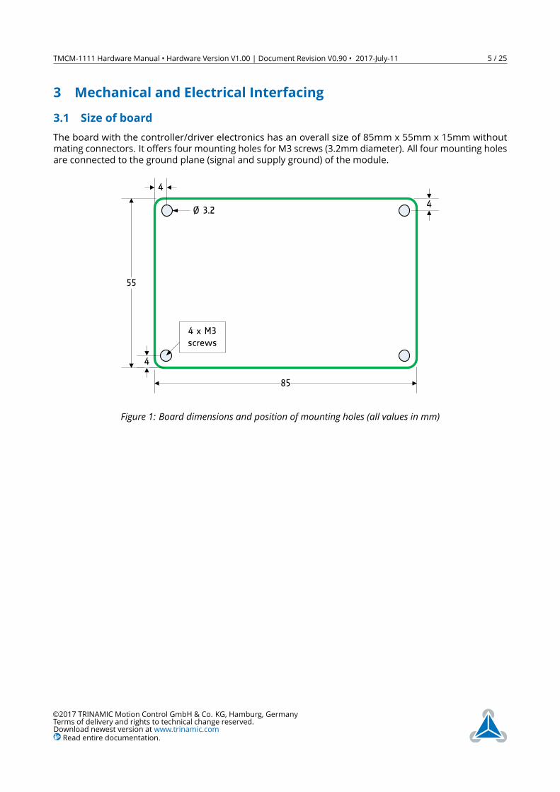
3 Mechanical and Electrical Interfacing3.1 Size of boardThe board with the controller/driver electronics has an overall size of 85mm x 55mm x 15mm withoutmating connectors. It offers four mounting holes for M3 screws (3.2mm diameter). All four mounting holesare connected to the ground plane (signal and supply ground) of the module.
85
55
4
4
4Ø 3.2
4 x M3screws
Figure 1: Board dimensions and position of mounting holes (all values in mm)
©2017 TRINAMIC Motion Control GmbH & Co. KG, Hamburg, GermanyTerms of delivery and rights to technical change reserved.Download newest version at www.trinamic.comRead entire documentation.
TMCM-1111 Hardware Manual • Hardware Version V1.00 | Document Revision V0.90 • 2017-July-11 6 / 25
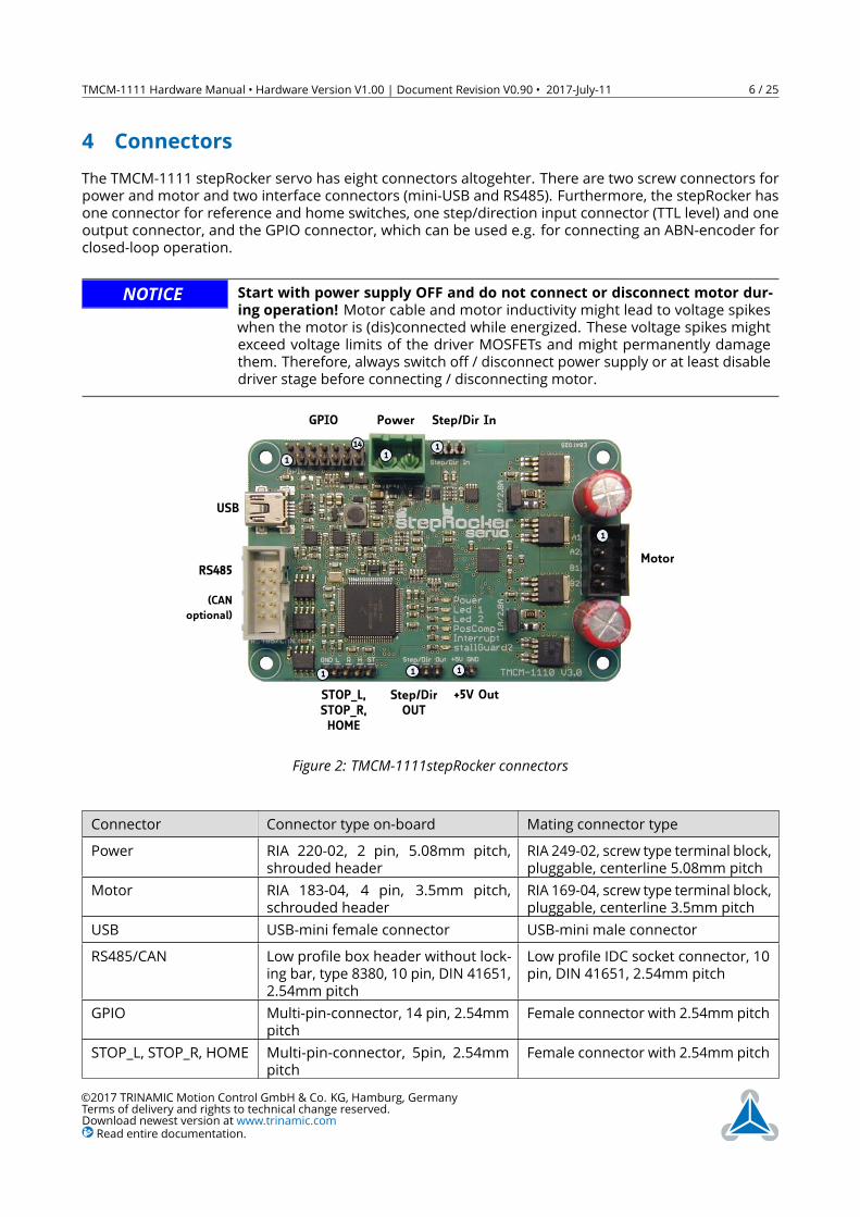
4 ConnectorsThe TMCM-1111 stepRocker servo has eight connectors altogehter. There are two screw connectors forpower and motor and two interface connectors (mini-USB and RS485). Furthermore, the stepRocker hasone connector for reference and home switches, one step/direction input connector (TTL level) and oneoutput connector, and the GPIO connector, which can be used e.g. for connecting an ABN-encoder forclosed-loop operation.
NOTICE Start with power supply OFF and do not connect or disconnect motor dur-ing operation! Motor cable and motor inductivity might lead to voltage spikeswhen the motor is (dis)connected while energized. These voltage spikes mightexceed voltage limits of the driver MOSFETs and might permanently damagethem. Therefore, always switch off / disconnect power supply or at least disabledriver stage before connecting / disconnecting motor.
PowerGPIO Step/Dir In
11
14 1
Motor
1
USB
RS485
(CANoptional)
STOP_L,STOP_R,HOME
Step/DirOUT
1 11
+5V Out
Figure 2: TMCM-1111stepRocker connectors
Connector Connector type on-board Mating connector typePower RIA 220-02, 2 pin, 5.08mm pitch,
shrouded headerRIA 249-02, screw type terminal block,pluggable, centerline 5.08mm pitch
Motor RIA 183-04, 4 pin, 3.5mm pitch,schrouded header
RIA 169-04, screw type terminal block,pluggable, centerline 3.5mm pitch
USB USB-mini female connector USB-mini male connectorRS485/CAN Low profile box header without lock-
ing bar, type 8380, 10 pin, DIN 41651,2.54mm pitch
Low profile IDC socket connector, 10pin, DIN 41651, 2.54mm pitch
GPIO Multi-pin-connector, 14 pin, 2.54mmpitch
Female connector with 2.54mm pitch
STOP_L, STOP_R, HOME Multi-pin-connector, 5pin, 2.54mmpitch
Female connector with 2.54mm pitch
©2017 TRINAMIC Motion Control GmbH & Co. KG, Hamburg, GermanyTerms of delivery and rights to technical change reserved.Download newest version at www.trinamic.comRead entire documentation.
TMCM-1111 Hardware Manual • Hardware Version V1.00 | Document Revision V0.90 • 2017-July-11 7 / 25
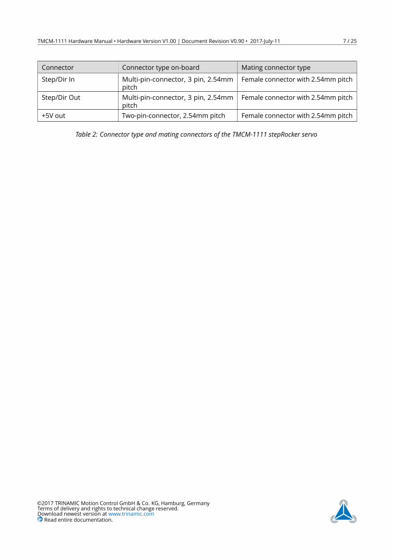
Connector Connector type on-board Mating connector typeStep/Dir In Multi-pin-connector, 3 pin, 2.54mm
pitchFemale connector with 2.54mm pitch
Step/Dir Out Multi-pin-connector, 3 pin, 2.54mmpitch
Female connector with 2.54mm pitch
+5V out Two-pin-connector, 2.54mm pitch Female connector with 2.54mm pitch
Table 2: Connector type and mating connectors of the TMCM-1111 stepRocker servo
©2017 TRINAMIC Motion Control GmbH & Co. KG, Hamburg, GermanyTerms of delivery and rights to technical change reserved.Download newest version at www.trinamic.comRead entire documentation.
TMCM-1111 Hardware Manual • Hardware Version V1.00 | Document Revision V0.90 • 2017-July-11 8 / 25
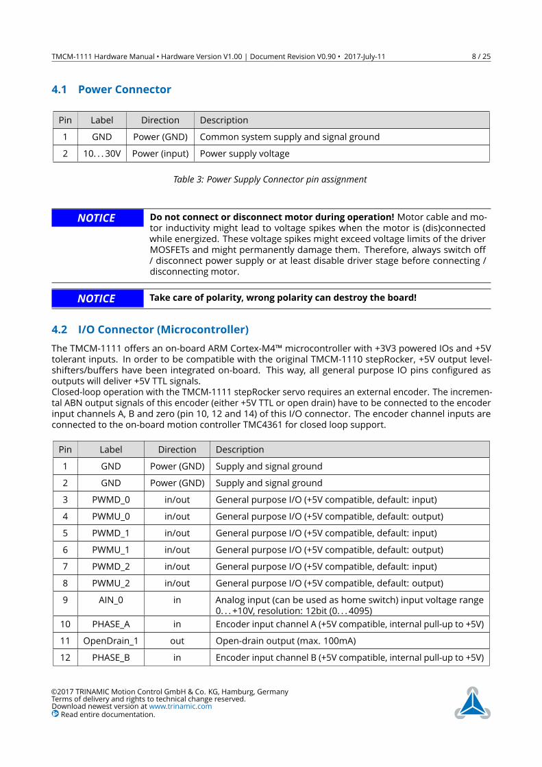
4.1 Power ConnectorPin Label Direction Description1 GND Power (GND) Common system supply and signal ground2 10. . . 30V Power (input) Power supply voltage
Table 3: Power Supply Connector pin assignment
NOTICE Do not connect or disconnect motor during operation! Motor cable and mo-tor inductivity might lead to voltage spikes when the motor is (dis)connectedwhile energized. These voltage spikes might exceed voltage limits of the driverMOSFETs and might permanently damage them. Therefore, always switch off/ disconnect power supply or at least disable driver stage before connecting /disconnecting motor.
NOTICE Take care of polarity, wrong polarity can destroy the board!
4.2 I/O Connector (Microcontroller)The TMCM-1111 offers an on-board ARM Cortex-M4™microcontroller with +3V3 powered IOs and +5Vtolerant inputs. In order to be compatible with the original TMCM-1110 stepRocker, +5V output level-shifters/buffers have been integrated on-board. This way, all general purpose IO pins configured asoutputs will deliver +5V TTL signals.Closed-loop operation with the TMCM-1111 stepRocker servo requires an external encoder. The incremen-tal ABN output signals of this encoder (either +5V TTL or open drain) have to be connected to the encoderinput channels A, B and zero (pin 10, 12 and 14) of this I/O connector. The encoder channel inputs areconnected to the on-board motion controller TMC4361 for closed loop support.
Pin Label Direction Description1 GND Power (GND) Supply and signal ground2 GND Power (GND) Supply and signal ground3 PWMD_0 in/out General purpose I/O (+5V compatible, default: input)4 PWMU_0 in/out General purpose I/O (+5V compatible, default: output)5 PWMD_1 in/out General purpose I/O (+5V compatible, default: input)6 PWMU_1 in/out General purpose I/O (+5V compatible, default: output)7 PWMD_2 in/out General purpose I/O (+5V compatible, default: input)8 PWMU_2 in/out General purpose I/O (+5V compatible, default: output)9 AIN_0 in Analog input (can be used as home switch) input voltage range
0. . . +10V, resolution: 12bit (0. . . 4095)10 PHASE_A in Encoder input channel A (+5V compatible, internal pull-up to +5V)11 OpenDrain_1 out Open-drain output (max. 100mA)12 PHASE_B in Encoder input channel B (+5V compatible, internal pull-up to +5V)
©2017 TRINAMIC Motion Control GmbH & Co. KG, Hamburg, GermanyTerms of delivery and rights to technical change reserved.Download newest version at www.trinamic.comRead entire documentation.
TMCM-1111 Hardware Manual • Hardware Version V1.00 | Document Revision V0.90 • 2017-July-11 9 / 25
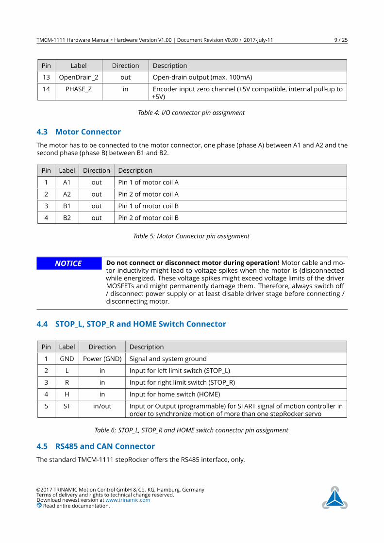
Pin Label Direction Description13 OpenDrain_2 out Open-drain output (max. 100mA)14 PHASE_Z in Encoder input zero channel (+5V compatible, internal pull-up to
+5V)
Table 4: I/O connector pin assignment
4.3 Motor ConnectorThe motor has to be connected to the motor connector, one phase (phase A) between A1 and A2 and thesecond phase (phase B) between B1 and B2.
Pin Label Direction Description1 A1 out Pin 1 of motor coil A2 A2 out Pin 2 of motor coil A3 B1 out Pin 1 of motor coil B4 B2 out Pin 2 of motor coil B
Table 5: Motor Connector pin assignment
NOTICE Do not connect or disconnect motor during operation! Motor cable and mo-tor inductivity might lead to voltage spikes when the motor is (dis)connectedwhile energized. These voltage spikes might exceed voltage limits of the driverMOSFETs and might permanently damage them. Therefore, always switch off/ disconnect power supply or at least disable driver stage before connecting /disconnecting motor.
4.4 STOP_L, STOP_R and HOME Switch ConnectorPin Label Direction Description1 GND Power (GND) Signal and system ground2 L in Input for left limit switch (STOP_L)3 R in Input for right limit switch (STOP_R)4 H in Input for home switch (HOME)5 ST in/out Input or Output (programmable) for START signal of motion controller in
order to synchronize motion of more than one stepRocker servo
Table 6: STOP_L, STOP_R and HOME switch connector pin assignment
4.5 RS485 and CAN ConnectorThe standard TMCM-1111 stepRocker offers the RS485 interface, only.
©2017 TRINAMIC Motion Control GmbH & Co. KG, Hamburg, GermanyTerms of delivery and rights to technical change reserved.Download newest version at www.trinamic.comRead entire documentation.
TMCM-1111 Hardware Manual • Hardware Version V1.00 | Document Revision V0.90 • 2017-July-11 10 / 25
Pin Label Direction Description123 CAN_L bi-directional differential CAN bus signal (inverting) - retro-fit option4 CAN_H bi-directional differential CAN bus signal (non-inverting) - retro-fit option5 GND Power (GND) Signal and system ground6 RS485+ bi-directional differential RS485 bus signal (non-inverting)7 RS485- bi-directional differential RS485 bus signal (inverting)8910
Table 7: RS485/CAN connector pin assignment
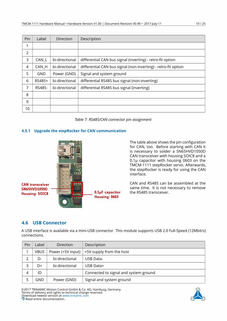
4.5.1 Upgrade the stepRocker for CAN communication
CAN transceiverSN65HVD1050DHousing: SOIC8 0.1µF capacitor
Housing: 0603
The table above shows the pin configurationfor CAN, too. Before starting with CAN itis necessary to solder a SN65HVD1050DCAN transceiver with housing SOIC8 and a0.1µ capacitor with housing 0603 on theTMCM-1111 stepRocker servo. Afterwards,the stepRocker is ready for using the CANinterface.CAN and RS485 can be assembled at thesame time. It is not necessary to removethe RS485 transceiver.
4.6 USB ConnectorA USB interface is available via a mini-USB connector. This module supports USB 2.0 Full-Speed (12Mbit/s)connections.
Pin Label Direction Description1 VBUS Power (+5V input) +5V supply from the host2 D- bi-directional USB Data-3 D+ bi-directional USB Data+4 ID Connected to signal and system ground5 GND Power (GND) Signal and system ground
©2017 TRINAMIC Motion Control GmbH & Co. KG, Hamburg, GermanyTerms of delivery and rights to technical change reserved.Download newest version at www.trinamic.comRead entire documentation.
TMCM-1111 Hardware Manual • Hardware Version V1.00 | Document Revision V0.90 • 2017-July-11 11 / 25
Pin Label Direction Description
Table 8: USB connector pin assignment
4.7 Step/Dir Input ConnectorThe TMCM-1111 stepRocker servo is equipped with a step/dir input connector. Via this connector the on-board motion controller can be synchronized to an external master (e.g. adding closed-loop functionality).Please refer to firmware manual for options and more details.
Pin Label Direction Description1 GND Power (GND) Signal and System ground2 Step In in Motion Controller step input signal (+5V compatible)3 Dir In in Motion Controller direction input signal (+5V compatible)
Table 9: Step/dir input connector pin assignment
4.8 Step/Dir Output ConnectorStep-/Dir output signals from the on-board motion controller maybe connected to an external driver stage(e.g. with different voltage and / or current rating) or used for synchronisation of two or more axes (e.g.when connected to Step-/Dir Input of another stepRocker servo).
Pin Label Direction Description1 GND Power (GND) Signal and System ground2 Step Out out Motion Controller step output signal (+5V compatible)3 Dir Out out Motion controller direction output signal (+5V compatible)
Table 10: Step/dir out connector pin assignment
4.9 +5V Out ConnectorIn contrast tot he earlier generation stepRocker family TMCM-1110 the stepRocker servo integrates aswitching DC/DC converter for generation of +5V digital supply on-board. This +5V are available alsoexternally via the +5V Out Connector - delivering up-to 100mA e.g. for supply of an external encoder orhome/end switch electronics.
Pin Label Direction Description1 GND Power (GND) Signal and System ground2 +5V out out +5V supply output. Can deliver up-to 100mA for external circuits e.g.
encoderTable 11: +5V Out connector pin assignment
©2017 TRINAMIC Motion Control GmbH & Co. KG, Hamburg, GermanyTerms of delivery and rights to technical change reserved.Download newest version at www.trinamic.comRead entire documentation.
TMCM-1111 Hardware Manual • Hardware Version V1.00 | Document Revision V0.90 • 2017-July-11 12 / 25
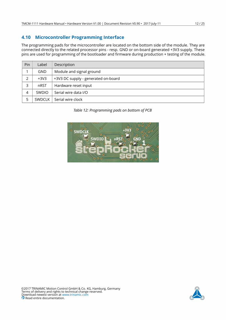
4.10 Microcontroller Programming InterfaceThe programming pads for the microcontroller are located on the bottom side of the module. They areconnected directly to the related processor pins - resp. GND or on-board generated +3V3 supply. Thesepins are used for programming of the bootloader and firmware during production + testing of the module.
Pin Label Description1 GND Module and signal ground2 +3V3 +3V3 DC supply - generated on-board3 nRST Hardware reset input4 SWDIO Serial wire data I/O5 SWDCLK Serial wire clock
Table 12: Programming pads on bottom of PCB
SWDCLK
nRST
+3V3
GND1
SWDIO
©2017 TRINAMIC Motion Control GmbH & Co. KG, Hamburg, GermanyTerms of delivery and rights to technical change reserved.Download newest version at www.trinamic.comRead entire documentation.
TMCM-1111 Hardware Manual • Hardware Version V1.00 | Document Revision V0.90 • 2017-July-11 13 / 25
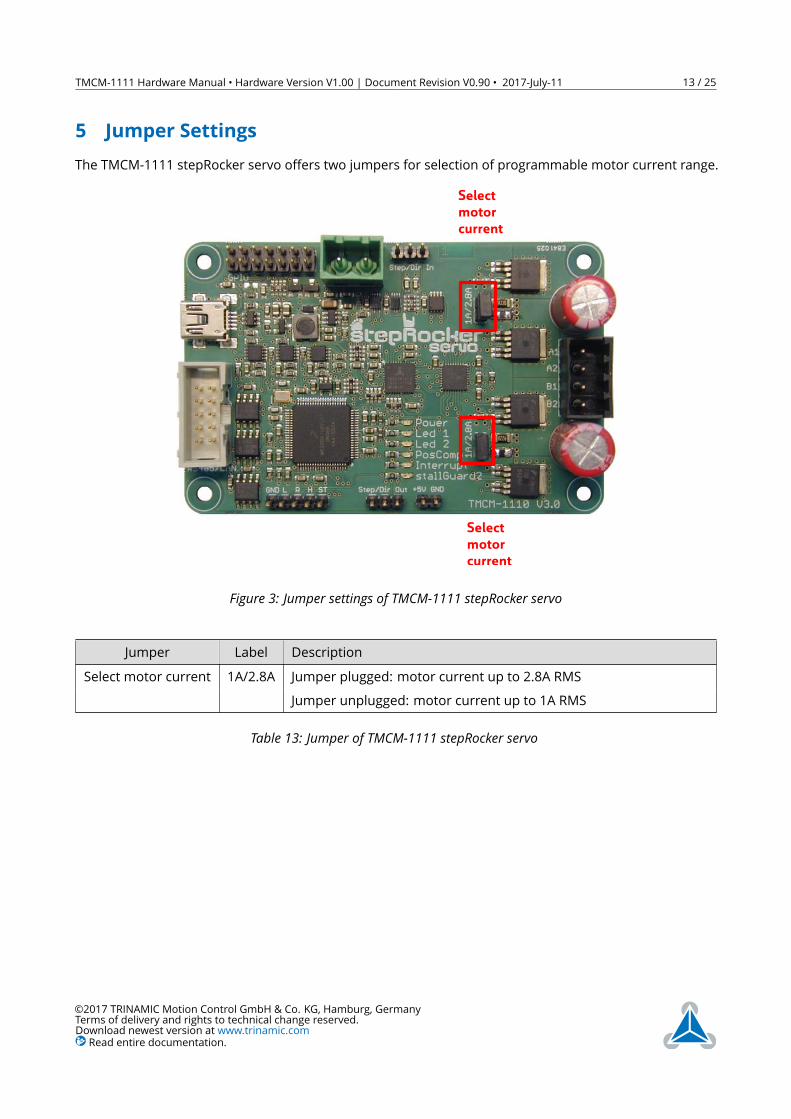
5 Jumper SettingsThe TMCM-1111 stepRocker servo offers two jumpers for selection of programmable motor current range.
Selectmotorcurrent
Selectmotorcurrent
Figure 3: Jumper settings of TMCM-1111 stepRocker servo
Jumper Label DescriptionSelect motor current 1A/2.8A Jumper plugged: motor current up to 2.8A RMS
Jumper unplugged: motor current up to 1A RMS
Table 13: Jumper of TMCM-1111 stepRocker servo
©2017 TRINAMIC Motion Control GmbH & Co. KG, Hamburg, GermanyTerms of delivery and rights to technical change reserved.Download newest version at www.trinamic.comRead entire documentation.

TMCM-1111 Hardware Manual • Hardware Version V1.00 | Document Revision V0.90 • 2017-July-11 14 / 25
6 LEDsStatus Label DescriptionPower on POWER This orange LED lights up upon the power sup-
ply is availableLED1 without pre-defined functionality LED1 This yellow LED can be used customer specific.
This LED is connected to PTA5 (pin 31) of theMK20DX128VLK7 microcontroller.
LED2 without pre-defined functionality LED2 This yellow LED can be used customer specific.This LED is connected to PTE5 (pin 6) of theMK20DX128VLK7 microcontroller.
POSCOMP output used POSCOMP
Interrupt detected Interrupt This orange LED lights up upon interrupts.The LED is connected to the INTR pin of theTMC4361.
stallGuard2™ detected stallGuard2 This red LED lights up upon stalling conditions.The LED is connected to the SG_TST pin of theTMC262.
Table 14: LED description
Figure 4: TMCM-1111 LEDs
©2017 TRINAMIC Motion Control GmbH & Co. KG, Hamburg, GermanyTerms of delivery and rights to technical change reserved.Download newest version at www.trinamic.comRead entire documentation.
TMCM-1111 Hardware Manual • Hardware Version V1.00 | Document Revision V0.90 • 2017-July-11 15 / 25
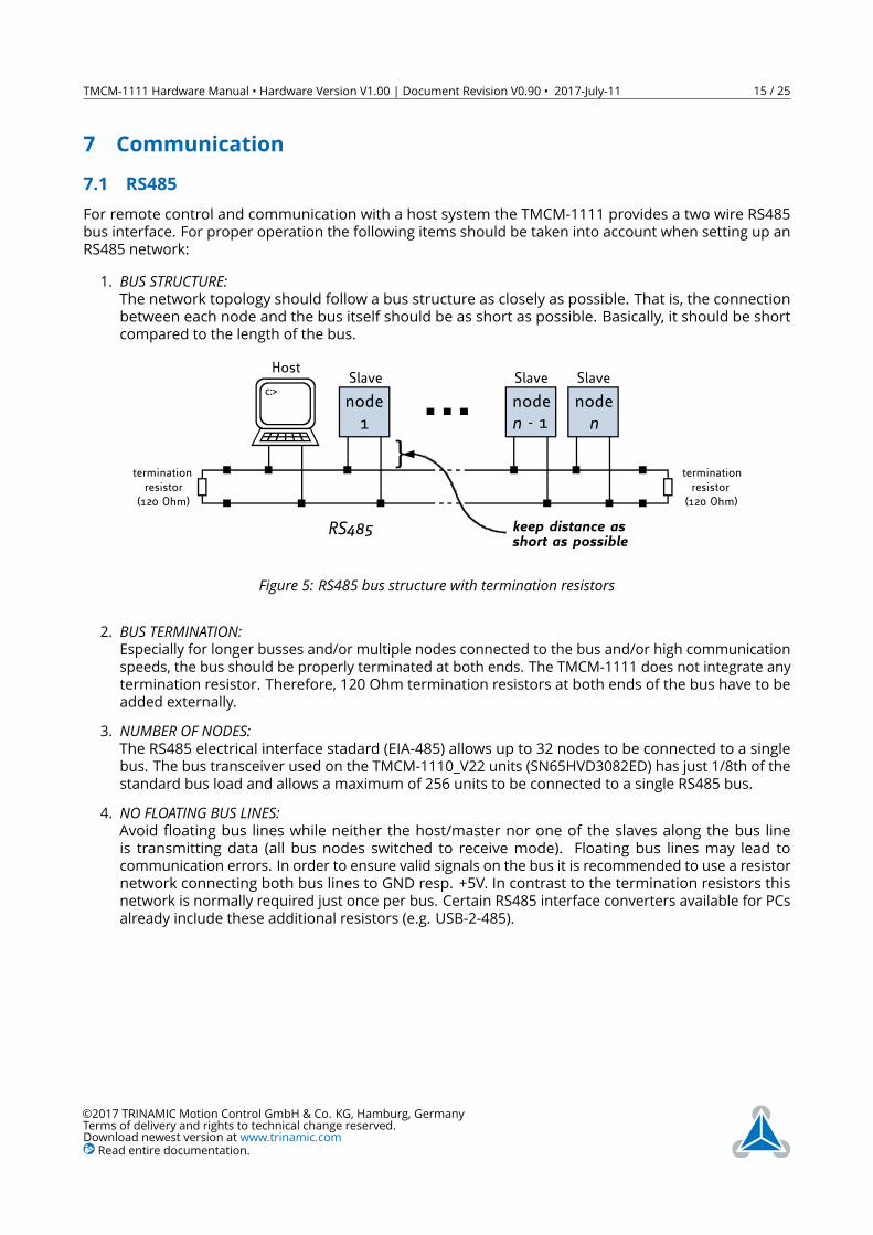
7 Communication7.1 RS485For remote control and communication with a host system the TMCM-1111 provides a two wire RS485bus interface. For proper operation the following items should be taken into account when setting up anRS485 network:1. BUS STRUCTURE:The network topology should follow a bus structure as closely as possible. That is, the connectionbetween each node and the bus itself should be as short as possible. Basically, it should be shortcompared to the length of the bus.
c:>node1
noden - 1
noden
HostSlave Slave Slave
RS485
terminationresistor
(120 Ohm)
terminationresistor(120 Ohm)
}
keep distance asshort as possible
Figure 5: RS485 bus structure with termination resistors
2. BUS TERMINATION:Especially for longer busses and/or multiple nodes connected to the bus and/or high communicationspeeds, the bus should be properly terminated at both ends. The TMCM-1111 does not integrate anytermination resistor. Therefore, 120 Ohm termination resistors at both ends of the bus have to beadded externally.
3. NUMBER OF NODES:The RS485 electrical interface stadard (EIA-485) allows up to 32 nodes to be connected to a singlebus. The bus transceiver used on the TMCM-1110_V22 units (SN65HVD3082ED) has just 1/8th of thestandard bus load and allows a maximum of 256 units to be connected to a single RS485 bus.
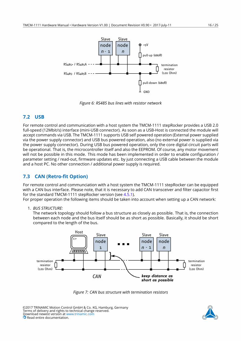
4. NO FLOATING BUS LINES:Avoid floating bus lines while neither the host/master nor one of the slaves along the bus lineis transmitting data (all bus nodes switched to receive mode). Floating bus lines may lead tocommunication errors. In order to ensure valid signals on the bus it is recommended to use a resistornetwork connecting both bus lines to GND resp. +5V. In contrast to the termination resistors thisnetwork is normally required just once per bus. Certain RS485 interface converters available for PCsalready include these additional resistors (e.g. USB-2-485).
©2017 TRINAMIC Motion Control GmbH & Co. KG, Hamburg, GermanyTerms of delivery and rights to technical change reserved.Download newest version at www.trinamic.comRead entire documentation.
TMCM-1111 Hardware Manual • Hardware Version V1.00 | Document Revision V0.90 • 2017-July-11 16 / 25
noden - 1
noden
Slave Slave
terminationresistor(120 Ohm)
+5V
GND
pull-up (680R)
pull-down (680R)
RS485- / RS485B
RS485+ / RS485A
Figure 6: RS485 bus lines with resistor network
7.2 USBFor remote control and communication with a host system the TMCM-1111 stepRocker provides a USB 2.0full-speed (12Mbit/s) interface (mini-USB connector). As soon as a USB-Host is connected the module willaccept commands via USB. The TMCM-1111 supports USB self powered operation (External power suppliedvia the power supply connector) and USB bus powered operation, also (no external power is supplied viathe power supply connector). During USB bus powered operation, only the core digital circuit parts willbe operational. That is, the microcontroller itself and also the EEPROM. Of course, any motor movementwill not be possible in this mode. This mode has been implemented in order to enable configuration /parameter setting / read-out, firmware updates etc. by just connecting a USB cable between the moduleand a host PC. No other connection / additional power supply is required.
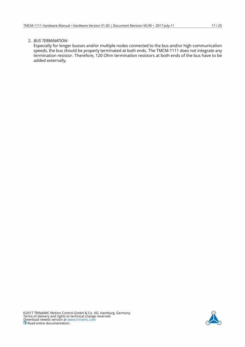
7.3 CAN (Retro-fit Option)For remote control and communciation with a host system the TMCM-1111 stepRocker can be equippedwith a CAN bus interface. Please note, that it is necessary to add CAN transceiver and filter capacitor firstfor the standard TMCM-1111 stepRocker version (see 4.5.1).For proper operation the following items should be taken into account when setting up a CAN network:1. BUS STRUCTURE:The network topology should follow a bus structure as closely as possible. That is, the connectionbetween each node and the bus itself should be as short as possible. Basically, it should be shortcompared to the length of the bus.
c:>node1
noden - 1
noden
HostSlave Slave Slave
CAN
terminationresistor
(120 Ohm)
terminationresistor(120 Ohm)
}
keep distance asshort as possible
Figure 7: CAN bus structure with termination resistors
©2017 TRINAMIC Motion Control GmbH & Co. KG, Hamburg, GermanyTerms of delivery and rights to technical change reserved.Download newest version at www.trinamic.comRead entire documentation.
TMCM-1111 Hardware Manual • Hardware Version V1.00 | Document Revision V0.90 • 2017-July-11 17 / 25
2. BUS TERMINATION:Especially for longer busses and/or multiple nodes connected to the bus and/or high communicationspeeds, the bus should be properly terminated at both ends. The TMCM-1111 does not integrate anytermination resistor. Therefore, 120 Ohm termination resistors at both ends of the bus have to beadded externally.
©2017 TRINAMIC Motion Control GmbH & Co. KG, Hamburg, GermanyTerms of delivery and rights to technical change reserved.Download newest version at www.trinamic.comRead entire documentation.
TMCM-1111 Hardware Manual • Hardware Version V1.00 | Document Revision V0.90 • 2017-July-11 18 / 25
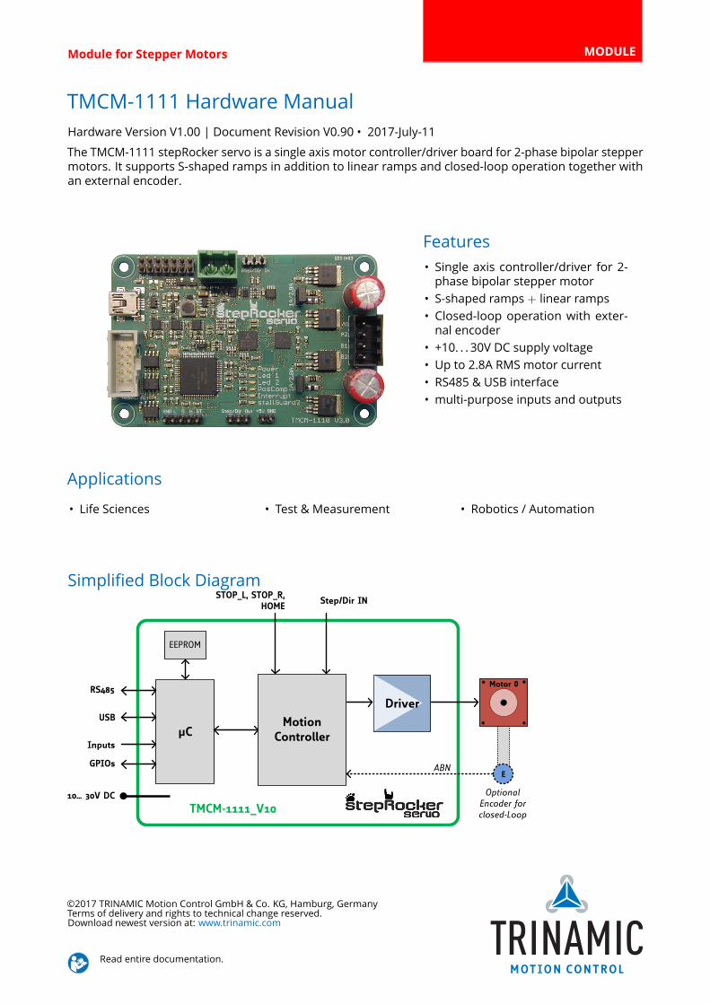
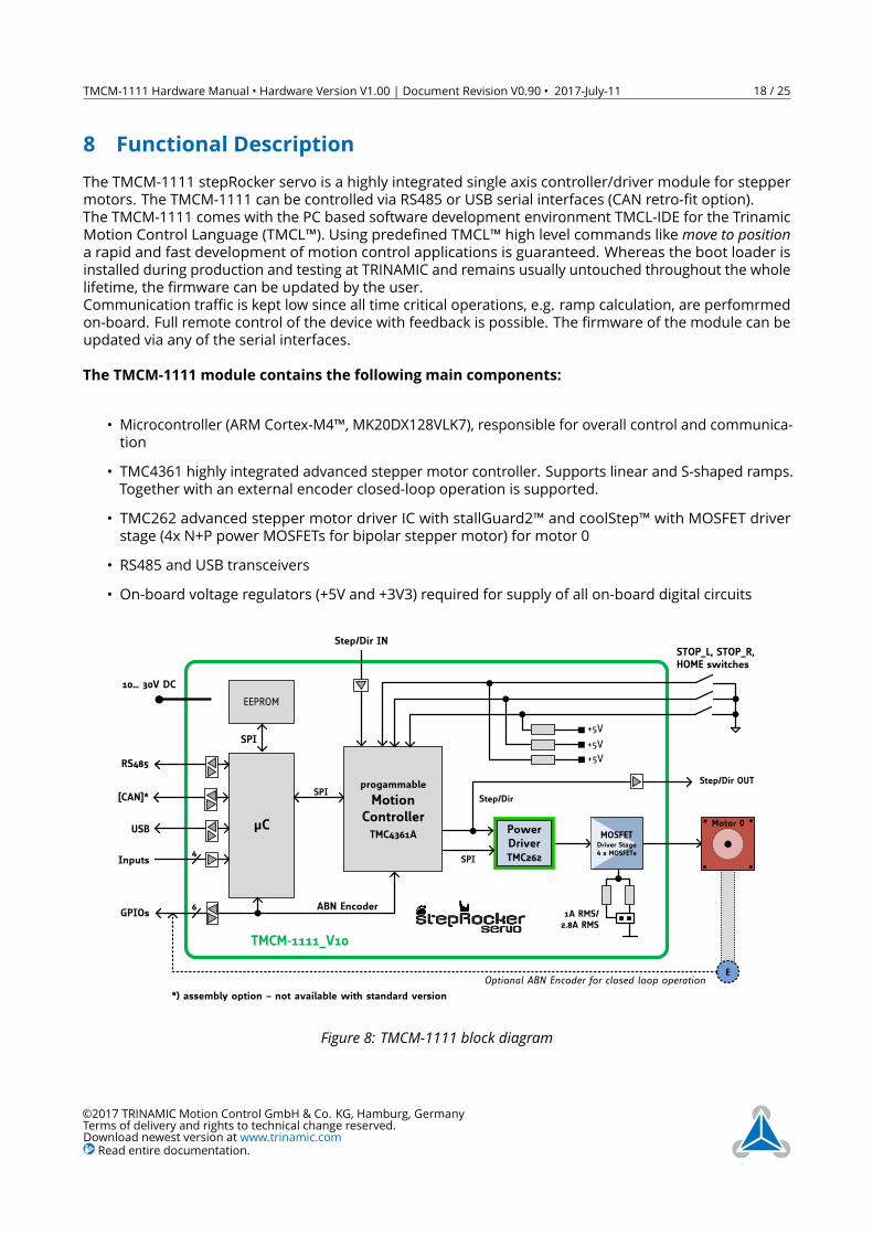
8 Functional DescriptionThe TMCM-1111 stepRocker servo is a highly integrated single axis controller/driver module for steppermotors. The TMCM-1111 can be controlled via RS485 or USB serial interfaces (CAN retro-fit option).The TMCM-1111 comes with the PC based software development environment TMCL-IDE for the TrinamicMotion Control Language (TMCL™). Using predefined TMCL™ high level commands likemove to positiona rapid and fast development of motion control applications is guaranteed. Whereas the boot loader isinstalled during production and testing at TRINAMIC and remains usually untouched throughout the wholelifetime, the firmware can be updated by the user.Communication traffic is kept low since all time critical operations, e.g. ramp calculation, are perfomrmedon-board. Full remote control of the device with feedback is possible. The firmware of the module can beupdated via any of the serial interfaces.The TMCM-1111 module contains the following main components:
• Microcontroller (ARM Cortex-M4™, MK20DX128VLK7), responsible for overall control and communica-tion
• TMC4361 highly integrated advanced stepper motor controller. Supports linear and S-shaped ramps.Together with an external encoder closed-loop operation is supported.
• TMC262 advanced stepper motor driver IC with stallGuard2™ and coolStep™ with MOSFET driverstage (4x N+P power MOSFETs for bipolar stepper motor) for motor 0
• RS485 and USB transceivers• On-board voltage regulators (+5V and +3V3) required for supply of all on-board digital circuits
N/… */V DC
µC
EEPROM
USB
)Inputs
progammable
MotionControllerTMC)*–NA
STOP_L8 STOP_R8HOME switches
+5V
–GPIOs
RS)[y
+5V
SPI
SPI
SPI
PowerDriverTMC.–.
MOSFETDriver Stage4 x MOSFETs
Step2Dir IN
NA RMS2.v[A RMS
Motor 0
hc assembly option – not available with standard version
[CAN]h
TMCM5NNNN_VN/
+5V
Step2Dir
Step2Dir OUT
ABN Encoder
EOptional ABN Encoder for closed loop operation
Figure 8: TMCM-1111 block diagram
©2017 TRINAMIC Motion Control GmbH & Co. KG, Hamburg, GermanyTerms of delivery and rights to technical change reserved.Download newest version at www.trinamic.comRead entire documentation.
TMCM-1111 Hardware Manual • Hardware Version V1.00 | Document Revision V0.90 • 2017-July-11 19 / 25
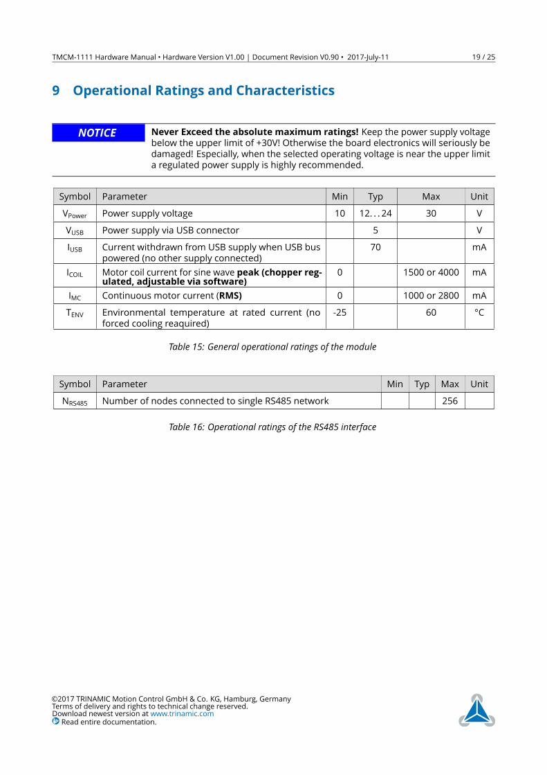
9 Operational Ratings and CharacteristicsNOTICE Never Exceed the absolute maximum ratings! Keep the power supply voltage
below the upper limit of +30V! Otherwise the board electronics will seriously bedamaged! Especially, when the selected operating voltage is near the upper limita regulated power supply is highly recommended.
Symbol Parameter Min Typ Max UnitVPower Power supply voltage 10 12. . . 24 30 VVUSB Power supply via USB connector 5 VIUSB Current withdrawn from USB supply when USB bus
powered (no other supply connected)70 mA
ICOIL Motor coil current for sine wave peak (chopper reg-ulated, adjustable via software) 0 1500 or 4000 mA
IMC Continuous motor current (RMS) 0 1000 or 2800 mATENV Environmental temperature at rated current (no
forced cooling reaquired)-25 60 °C
Table 15: General operational ratings of the module
Symbol Parameter Min Typ Max UnitNRS485 Number of nodes connected to single RS485 network 256
Table 16: Operational ratings of the RS485 interface
©2017 TRINAMIC Motion Control GmbH & Co. KG, Hamburg, GermanyTerms of delivery and rights to technical change reserved.Download newest version at www.trinamic.comRead entire documentation.
TMCM-1111 Hardware Manual • Hardware Version V1.00 | Document Revision V0.90 • 2017-July-11 20 / 25
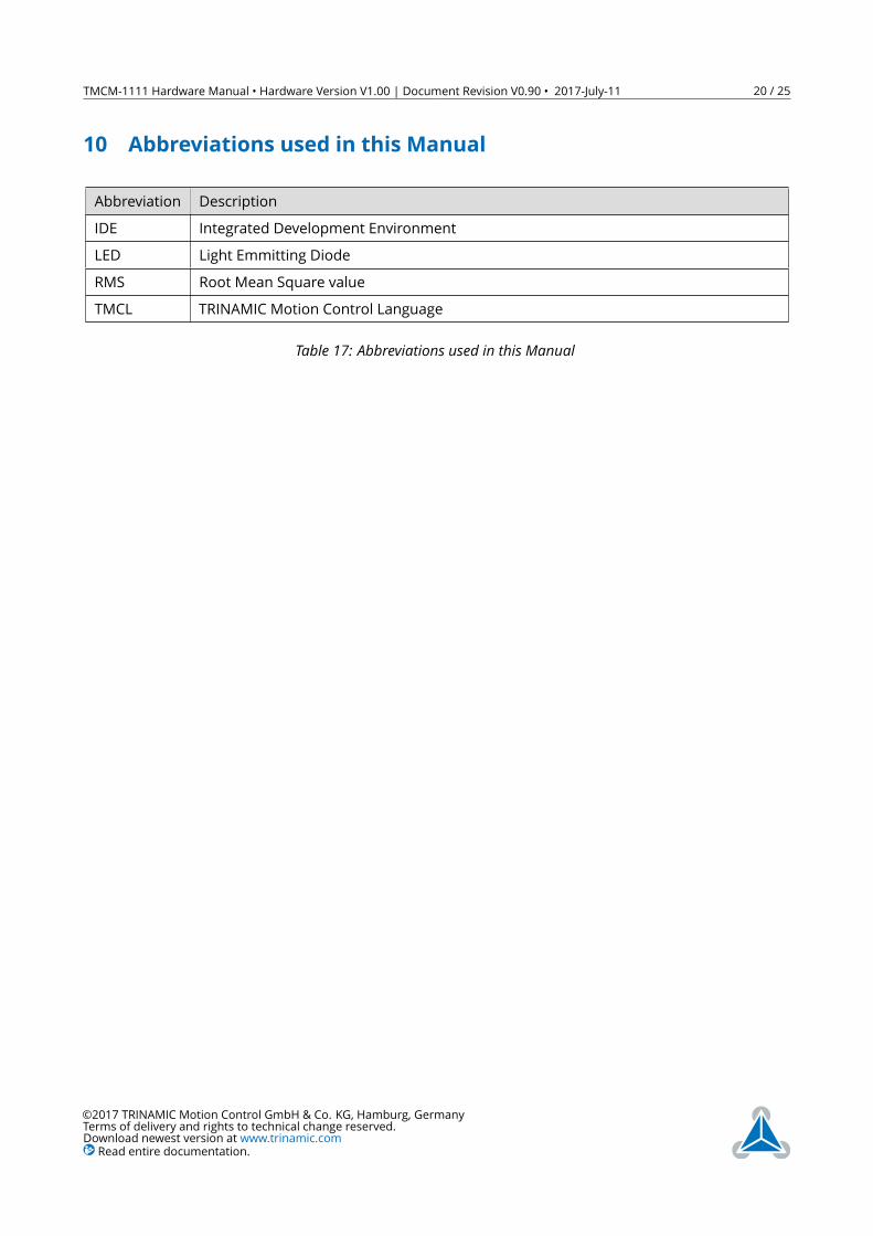
10 Abbreviations used in this ManualAbbreviation DescriptionIDE Integrated Development EnvironmentLED Light Emmitting DiodeRMS Root Mean Square valueTMCL TRINAMIC Motion Control Language
Table 17: Abbreviations used in this Manual
©2017 TRINAMIC Motion Control GmbH & Co. KG, Hamburg, GermanyTerms of delivery and rights to technical change reserved.Download newest version at www.trinamic.comRead entire documentation.
TMCM-1111 Hardware Manual • Hardware Version V1.00 | Document Revision V0.90 • 2017-July-11 21 / 25
11 Figures Index1 Board dimensions and position of
mounting holes (all values in mm) . . 52 TMCM-1111stepRocker connectors . 63 Jumper settings of TMCM-1111
stepRocker servo . . . . . . . . . . . . 134 TMCM-1111 LEDs . . . . . . . . . . . . 14
5 RS485 bus structure with terminationresistors . . . . . . . . . . . . . . . . . 15
6 RS485 bus lines with resistor network 167 CAN bus structure with termination
resistors . . . . . . . . . . . . . . . . . 168 TMCM-1111 block diagram . . . . . . 18
©2017 TRINAMIC Motion Control GmbH & Co. KG, Hamburg, GermanyTerms of delivery and rights to technical change reserved.Download newest version at www.trinamic.comRead entire documentation.
TMCM-1111 Hardware Manual • Hardware Version V1.00 | Document Revision V0.90 • 2017-July-11 22 / 25
12 Tables Index1 TMCM-1111_V10 Order code . . . . . 42 Connector type and mating connec-
tors of the TMCM-1111 stepRocker servo 73 Power Supply Connector pin assignment 84 I/O connector pin assignment . . . . . 95 Motor Connector pin assignment . . 96 STOP_L, STOP_R and HOME switch
connector pin assignment . . . . . . . 97 RS485/CAN connector pin assignment 108 USB connector pin assignment . . . . 119 Step/dir input connector pin assignment 1110 Step/dir out connector pin assignment 11
11 +5V Out connector pin assignment . . 1112 Programming pads on bottom of PCB 1213 Jumper of TMCM-1111 stepRocker servo 1314 LED description . . . . . . . . . . . . . 1415 General operational ratings of the
module . . . . . . . . . . . . . . . . . . 1916 Operational ratings of the RS485 inter-
face . . . . . . . . . . . . . . . . . . . . 1917 Abbreviations used in this Manual . . 2018 Hardware Revision . . . . . . . . . . . 2519 Document Revision . . . . . . . . . . . 25
©2017 TRINAMIC Motion Control GmbH & Co. KG, Hamburg, GermanyTerms of delivery and rights to technical change reserved.Download newest version at www.trinamic.comRead entire documentation.
TMCM-1111 Hardware Manual • Hardware Version V1.00 | Document Revision V0.90 • 2017-July-11 23 / 25
13 Supplemental Directives13.1 Producer Information13.2 CopyrightTRINAMIC owns the content of this user manual in its entirety, including but not limited to pictures, logos,trademarks, and resources. © Copyright 2017 TRINAMIC. All rights reserved. Electronically published byTRINAMIC, Germany.Redistributions of source or derived format (for example, Portable Document Format or Hypertext MarkupLanguage) must retain the above copyright notice, and the complete Datasheet User Manual docu-mentation of this product including associated Application Notes; and a reference to other availableproduct-related documentation.
13.3 Trademark Designations and SymbolsTrademark designations and symbols used in this documentation indicate that a product or feature isowned and registered as trademark and/or patent either by TRINAMIC or by other manufacturers, whoseproducts are used or referred to in combination with TRINAMIC’s products and TRINAMIC’s product docu-mentation.This HardwareManual is a non-commercial publication that seeks to provide concise scientific and technicaluser information to the target user. Thus, trademark designations and symbols are only entered in theShort Spec of this document that introduces the product at a quick glance. The trademark designation/symbol is also entered when the product or feature name occurs for the first time in the document. Alltrademarks and brand names used are property of their respective owners.
13.4 Target UserThe documentation provided here, is for programmers and engineers only, who are equipped with thenecessary skills and have been trained to work with this type of product.The Target User knows how to responsibly make use of this product without causing harm to himself orothers, and without causing damage to systems or devices, in which the user incorporates the product.
13.5 Disclaimer: Life Support SystemsTRINAMIC Motion Control GmbH & Co. KG does not authorize or warrant any of its products for use in lifesupport systems, without the specific written consent of TRINAMIC Motion Control GmbH & Co. KG.Life support systems are equipment intended to support or sustain life, and whose failure to perform,when properly used in accordance with instructions provided, can be reasonably expected to result inpersonal injury or death.Information given in this document is believed to be accurate and reliable. However, no responsibilityis assumed for the consequences of its use nor for any infringement of patents or other rights of thirdparties which may result from its use. Specifications are subject to change without notice.
13.6 Disclaimer: Intended UseThe data specified in this user manual is intended solely for the purpose of product description. No repre-sentations or warranties, either express or implied, of merchantability, fitness for a particular purpose
©2017 TRINAMIC Motion Control GmbH & Co. KG, Hamburg, GermanyTerms of delivery and rights to technical change reserved.Download newest version at www.trinamic.comRead entire documentation.

TMCM-1111 Hardware Manual • Hardware Version V1.00 | Document Revision V0.90 • 2017-July-11 24 / 25
or of any other nature are made hereunder with respect to information/specification or the products towhich information refers and no guarantee with respect to compliance to the intended use is given.In particular, this also applies to the stated possible applications or areas of applications of the product.TRINAMIC products are not designed for and must not be used in connection with any applications wherethe failure of such products would reasonably be expected to result in significant personal injury or death(safety-Critical Applications) without TRINAMIC’s specific written consent.TRINAMIC products are not designed nor intended for use in military or aerospace applications or environ-ments or in automotive applications unless specifically designated for such use by TRINAMIC. TRINAMICconveys no patent, copyright, mask work right or other trademark right to this product. TRINAMIC assumesno liability for any patent and/or other trade mark rights of a third party resulting from processing orhandling of the product and/or any other use of the product.
13.7 Collateral Documents & ToolsThis product documentation is related and/or associated with additional tool kits, firmware and otheritems, as provided on the product page at: www.trinamic.com.
©2017 TRINAMIC Motion Control GmbH & Co. KG, Hamburg, GermanyTerms of delivery and rights to technical change reserved.Download newest version at www.trinamic.comRead entire documentation.
TMCM-1111 Hardware Manual • Hardware Version V1.00 | Document Revision V0.90 • 2017-July-11 25 / 25
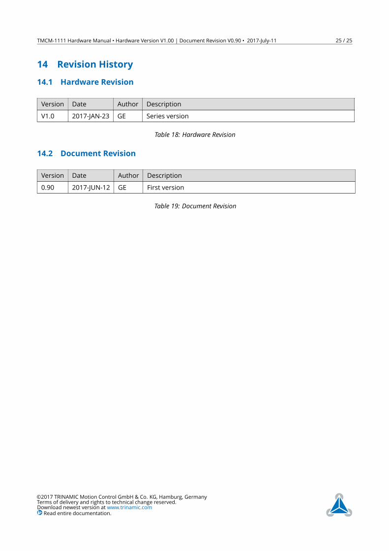
14 Revision History14.1 Hardware RevisionVersion Date Author DescriptionV1.0 2017-JAN-23 GE Series version
Table 18: Hardware Revision
14.2 Document RevisionVersion Date Author Description0.90 2017-JUN-12 GE First version
Table 19: Document Revision
©2017 TRINAMIC Motion Control GmbH & Co. KG, Hamburg, GermanyTerms of delivery and rights to technical change reserved.Download newest version at www.trinamic.comRead entire documentation.