Embed Size (px)
Citation preview

To Get a Perfect To Get a Perfect “A”…“A”…
An Engr. 311 Project by Corrin Meyer
Project StatementProject Statement
The tuner should generate a pure and The tuner should generate a pure and perfect A. perfect A. The sine wave should oscillate to with in 5% The sine wave should oscillate to with in 5%
of 440 Hz (which is a perfect tuning A).of 440 Hz (which is a perfect tuning A). The sine wave should have as little The sine wave should have as little
distortion as possible.distortion as possible. The tuner should be able to drive a The tuner should be able to drive a
speaker.speaker. The tuner should be portable (in The tuner should be portable (in
concept).concept).
Design ProcessDesign Process
Research sinusoidal oscillators.Research sinusoidal oscillators. Understand benefits and pitfalls of Understand benefits and pitfalls of
different oscillator designs.different oscillator designs. Choose an appropriate oscillator.Choose an appropriate oscillator. Improve basic circuit design.Improve basic circuit design.
Basic Theory of Basic Theory of OscillatorsOscillators
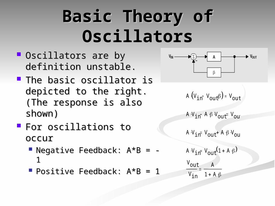
Oscillators are by Oscillators are by definition unstable.definition unstable.
The basic oscillator is The basic oscillator is depicted to the right. depicted to the right. (The response is also (The response is also shown)shown)
For oscillations to occurFor oscillations to occur Negative Feedback: A*B = Negative Feedback: A*B =
-1-1 Positive Feedback: A*B = 1Positive Feedback: A*B = 1
A Vin Vout Vout
A Vin A Vout Vout
A Vin Vout A Vout
A Vin Vout 1 A
Vout
Vin
A
1 A
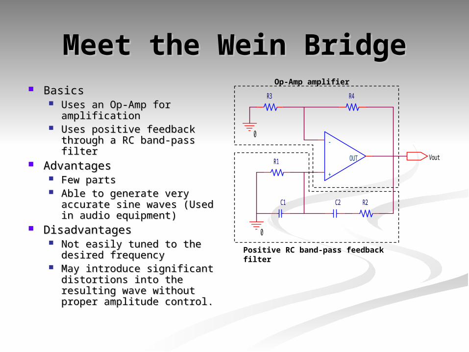
Meet the Wein BridgeMeet the Wein Bridge BasicsBasics
Uses an Op-Amp for Uses an Op-Amp for amplificationamplification
Uses positive feedback Uses positive feedback through a RC band-pass through a RC band-pass filterfilter
AdvantagesAdvantages Few partsFew parts Able to generate very Able to generate very
accurate sine waves (Used in accurate sine waves (Used in audio equipment)audio equipment)
DisadvantagesDisadvantages Not easily tuned to the Not easily tuned to the
desired frequencydesired frequency May introduce significant May introduce significant
distortions into the resulting distortions into the resulting wave without proper wave without proper amplitude control.amplitude control.
R2
R4R3
R1
C2C1
0
0
+
-
OUT Vout
Positive RC band-pass feedback filter
Op-Amp amplifier
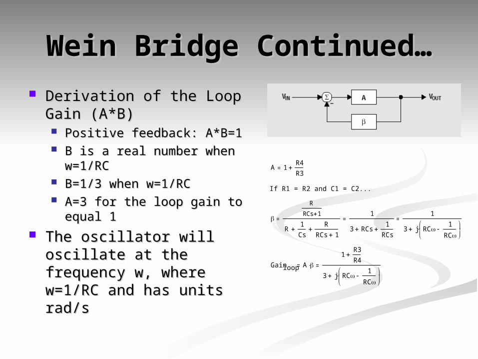
Wein Bridge Continued…Wein Bridge Continued… Derivation of the Loop Derivation of the Loop
Gain (A*B)Gain (A*B) Positive feedback: A*B=1Positive feedback: A*B=1 B is a real number when B is a real number when
w=1/RCw=1/RC B=1/3 when w=1/RCB=1/3 when w=1/RC A=3 for the loop gain to A=3 for the loop gain to
equal 1equal 1 The oscillator will The oscillator will
oscillate at the frequency oscillate at the frequency w, where w=1/RC and w, where w=1/RC and has units rad/shas units rad/s
A 1R4
R3
If R1 = R2 and C1 = C2...
R
RCs 1
R1
Cs
R
RCs 1
1
3 RCs1
RCs
1
3 j RC1
RC
Gainloop A 1
R3
R4
3 j RC1
RC
The Wein Bridge The Wein Bridge ProblemProblem
For oscillations to start, A must be slightly For oscillations to start, A must be slightly greater than 3.greater than 3.
If A is greater than 3 , then the loop gain is If A is greater than 3 , then the loop gain is greater than 1.greater than 1.
If the loop gain is greater than 1, then the If the loop gain is greater than 1, then the sine wave amplitude will tend towards sine wave amplitude will tend towards infinity.infinity.
Circuit does not infinite power, so the Circuit does not infinite power, so the output sine wave becomes severely output sine wave becomes severely distorted.distorted.
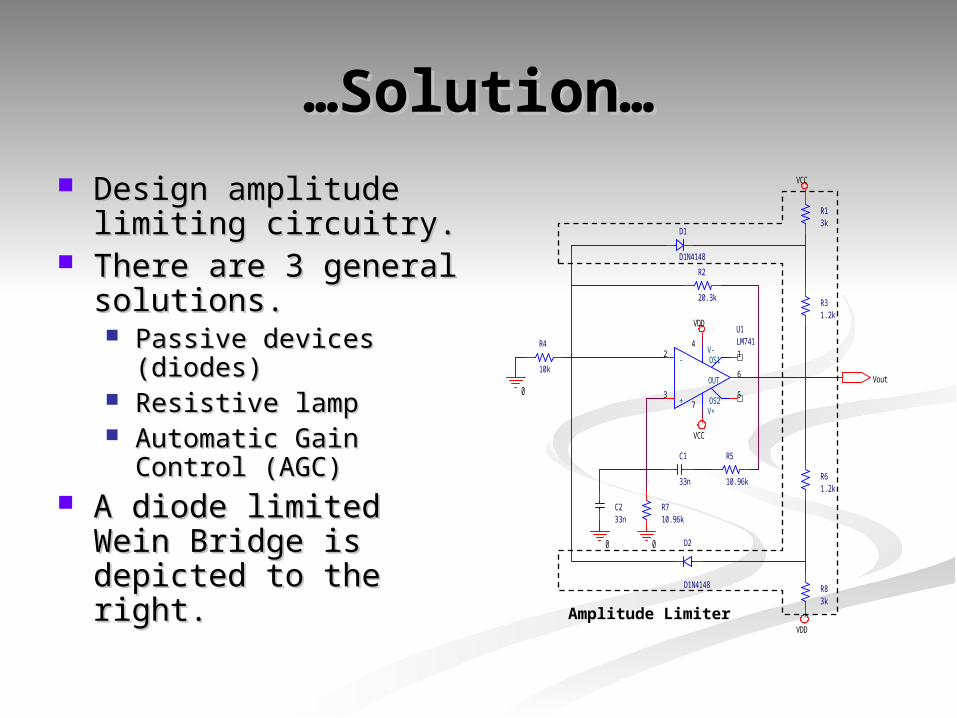
……Solution…Solution… Design amplitude Design amplitude
limiting circuitry.limiting circuitry. There are 3 general There are 3 general
solutions.solutions. Passive devices Passive devices
(diodes)(diodes) Resistive lampResistive lamp Automatic Gain Control Automatic Gain Control
(AGC)(AGC) A diode limited Wein A diode limited Wein
Bridge is depicted to Bridge is depicted to the right.the right.
R2
20.3k
R4
10k
R5
10.96k
R710.96k
R83k
R61.2k
R31.2k
R13k
C1
33n
C233n
D1
D1N4148
D2
D1N4148
0 0
0
U1LM741
+3
-2
V+7
V-4
OUT6
OS11
OS25
VCC
VDD
VCC
VDD
Vout
Amplitude Limiter
Not So Perfect…Not So Perfect…
The diode limited Wein Bridge does The diode limited Wein Bridge does NOT produce a perfect sine wave.NOT produce a perfect sine wave.
The amplifier gain is different when The amplifier gain is different when the diodes conduct and when they the diodes conduct and when they do not conduct.do not conduct.
Result: Distorted sine wave.Result: Distorted sine wave. Solution: AGCSolution: AGC
The All Mighty AGCThe All Mighty AGC
AGC stands for Automatic Gain AGC stands for Automatic Gain Control.Control. Controls the gain of the amplifier based Controls the gain of the amplifier based
on the output sine wave amplitude.on the output sine wave amplitude. The AGC requires two parts…The AGC requires two parts…
An AC rectifier with signal smoothing.An AC rectifier with signal smoothing. A VCR (Voltage Controlled Resistor).A VCR (Voltage Controlled Resistor).
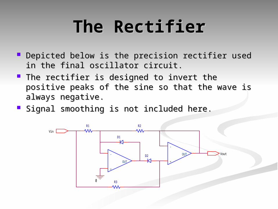
The RectifierThe Rectifier Depicted below is the precision rectifier used in the Depicted below is the precision rectifier used in the
final oscillator circuit.final oscillator circuit. The rectifier is designed to invert the positive peaks The rectifier is designed to invert the positive peaks
of the sine so that the wave is always negative.of the sine so that the wave is always negative. Signal smoothing is not included here.Signal smoothing is not included here.
R3
R1 R2
D2
D1
0
Vin
Vout
+
-
OUT +
-
OUT
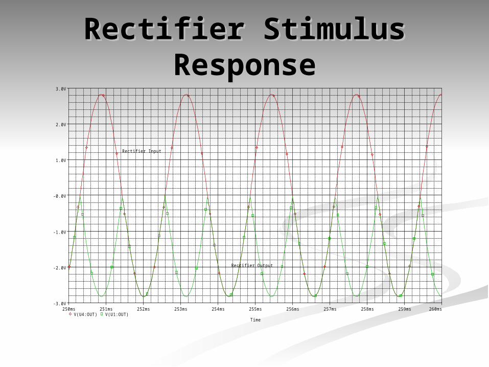
Rectifier Stimulus Rectifier Stimulus ResponseResponse
Time
250ms 251ms 252ms 253ms 254ms 255ms 256ms 257ms 258ms 259ms 260msV(U4:OUT) V(U1:OUT)
-3.0V
-2.0V
-1.0V
-0.0V
1.0V
2.0V
3.0V
Rectifier Output
Rectifier Input
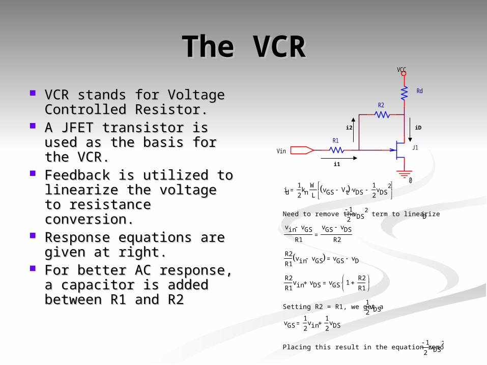
The VCRThe VCR VCR stands for Voltage VCR stands for Voltage
Controlled Resistor.Controlled Resistor. A JFET transistor is A JFET transistor is
used as the basis for used as the basis for the VCR.the VCR.
Feedback is utilized to Feedback is utilized to linearize the voltage to linearize the voltage to resistance conversion.resistance conversion.
Response equations are Response equations are given at right.given at right.
For better AC response, For better AC response, a capacitor is added a capacitor is added between R1 and R2between R1 and R2
J1
R2
0
R1
Rd
VCC
Vin
i1
i2 iD
id1
2kn
W
LvGS Vt vDS
1
2vDS
2
Need to remove the 12
vDS2 term to linearize iD
vin vGS
R1
vGS vDS
R2
R2
R1vin vGS vGS vD
R2
R1vin vDS vGS 1
R2
R1
Setting R2 = R1, we get a 1
2vDS
vGS1
2vin
1
2vDS
Placing this result in the equation removes the 12
vDS2
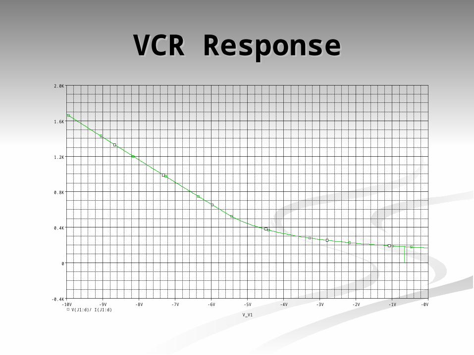
VCR ResponseVCR Response
V_V1
-10V -9V -8V -7V -6V -5V -4V -3V -2V -1V -0VV(J1:d)/ I(J1:d)
-0.4K
0
0.4K
0.8K
1.2K
1.6K
2.0K
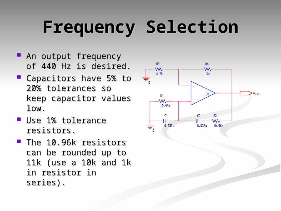
Frequency SelectionFrequency Selection An output frequency of An output frequency of
440 Hz is desired.440 Hz is desired. Capacitors have 5% to Capacitors have 5% to
20% tolerances so 20% tolerances so keep capacitor values keep capacitor values low.low.
Use 1% tolerance Use 1% tolerance resistors.resistors.
The 10.96k resistors The 10.96k resistors can be rounded up to can be rounded up to 11k (use a 10k and 1k 11k (use a 10k and 1k in resistor in series).in resistor in series).
0
0
+
-
OUT Vout
R3
4.7k
R4
10k
R1
10.96k
R2
10.96k
C1
0.033u
C2
0.033u
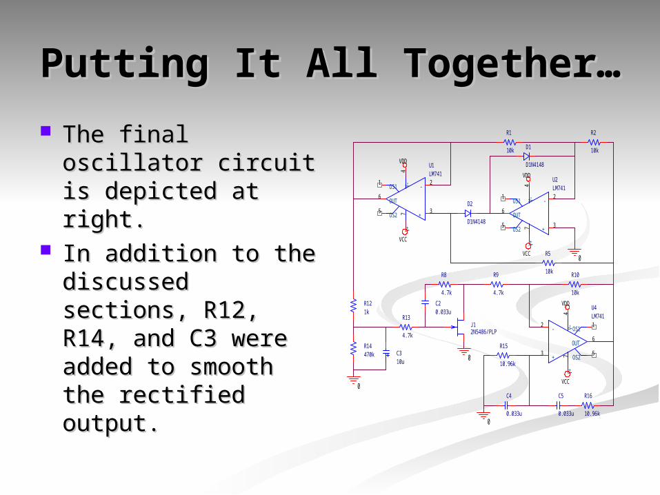
Putting It All Together…Putting It All Together…
The final oscillator The final oscillator circuit is depicted circuit is depicted at right.at right.
In addition to the In addition to the discussed sections, discussed sections, R12, R14, and C3 R12, R14, and C3 were added to were added to smooth the smooth the rectified output.rectified output.
J12N5486/PLP
U4LM741
+3
-2
V+7
V-4
OUT6
OS11
OS25
R16
10.96k
R10
10k
R9
4.7k
R15
10.96k
R8
4.7k
R5
10k
R2
10k
R1
10k
R14470k
C5
0.033u
C4
0.033u
C20.033u
C310u
U2LM741
+3
-2
V+7
V-4
OUT6
OS11
OS25
U1LM741
+3
-2
V+7
V-4
OUT6
OS11
OS25
D2
D1N4148
D1
D1N4148
R13
4.7k
VDD
VDD
VCC
VDD
VCC
VCC
0
0
0
0
R121k
Additional ImprovementsAdditional Improvements
Run on batteries.Run on batteries. Volume control could be added.Volume control could be added. The 741 Op-Amp can only source The 741 Op-Amp can only source
about 50mA of current so an output about 50mA of current so an output stage to drive a speaker could be stage to drive a speaker could be implemented.implemented.
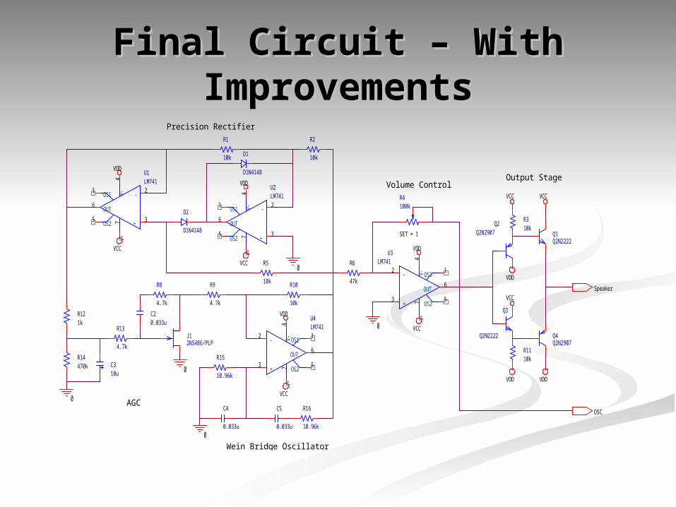
Final Circuit – With Final Circuit – With ImprovementsImprovements
Wein Bridge Oscillator
Precision Rectifier
AGC
Output StageVolume Control
Q4Q2N2907
Q2Q2N2907 Q1
Q2N2222
Q3
Q2N2222
VDD
VDD
VCC
VDD
VCC
R310k
R1110k
VCC
Speaker
U3LM741
+3
-2
V+7
V-4
OUT6
OS11
OS25
R6
47k
R4100k
SET = 1
VDD
VCC0J12N5486/PLP
U4LM741
+3
-2
V+7
V-4
OUT6
OS11
OS25
R16
10.96k
R10
10k
R9
4.7k
R15
10.96k
R8
4.7k
R5
10k
R2
10k
R1
10k
R14470k
C5
0.033u
C4
0.033u
C20.033u
C310u
U2LM741
+3
-2
V+7
V-4
OUT6
OS11
OS25
U1LM741
+3
-2
V+7
V-4
OUT6
OS11
OS25
D2
D1N4148
D1
D1N4148
R13
4.7k
VDD
VDD
VCC
VDD
VCC
VCC
0
0
0
0
OSC
R121k
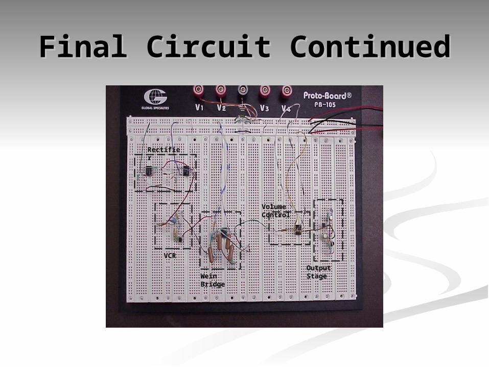
Final Circuit ContinuedFinal Circuit Continued
Rectifier
VCR
Wein Bridge
Volume Control
Output Stage
Operation of Circuit in Operation of Circuit in Real LifeReal Life
The output sine wave is much smaller than The output sine wave is much smaller than predicted.predicted. Predicted amplitude: 3VPredicted amplitude: 3V Actual amplitude: 25mVActual amplitude: 25mV This is due to extreme dependence on Wein Bridge This is due to extreme dependence on Wein Bridge
amplifier gain setting resistors.amplifier gain setting resistors. Volume control can make up for the smaller amplitude Volume control can make up for the smaller amplitude
without introducing distortion.without introducing distortion. The output sine wave is very clean and precise.The output sine wave is very clean and precise. The output frequency is surprisingly close to the The output frequency is surprisingly close to the
ideal frequency that was designed for. (plus or ideal frequency that was designed for. (plus or minus 5Hz)minus 5Hz)
Final CommentsFinal Comments
AccomplishmentsAccomplishments Generates a near perfect sine wave (when taken Generates a near perfect sine wave (when taken
directly from the oscillator circuit) at around directly from the oscillator circuit) at around 440Hz.440Hz.
Runs of batteries.Runs of batteries. Areas needing further Areas needing further
development/improvement.development/improvement. Output stage introduces some distortion.Output stage introduces some distortion. Make the oscillator easier to tune. (plus or Make the oscillator easier to tune. (plus or
minus 10Hz)minus 10Hz) Improve the AGC amplitude detection.Improve the AGC amplitude detection.