Embed Size (px)
Citation preview
WA
RR
AN
TY
:Top Flite M
odels guarantees this kitto
be free
from
defects in
both m
aterial and
workm
an
ship
a
t th
e
da
te
of
pu
rcha
se.T
his
warranty
does not
cover any
component
partsdam
aged by use or modification.
In no case shallTop F
lite’s liability exceed the original cost of thepurchased kit.F
urther, Top Flite reserves the right
to change or modify this w
arranty without notice.In
that Top Flite has no control over the final assem
blyor m
aterial used for final assembly, no liability shall
be
a
ssum
ed
n
or
acce
pte
d
for
any
da
ma
ge
resulting from the use by the user of the final user-
assembled product.
By the act of using the user-
assembled product, the user accepts all resulting
liability.If the bu
yer is no
t prep
ared to
accept th
eliab
ility associated
with
the u
se of th
is pro
du
ct,th
e b
uyer
is ad
vised
to
return
th
is kit
imm
ediately in
new
and
un
used
con
ditio
n to
the p
lace of p
urch
ase.To make a w
arranty claimsend the defective part or item
to Hobby S
ervicesat the address below
.
Ho
bby S
ervices3002 N
.Ap
ollo
Dr.
Su
ite 1C
ham
paig
n IL
61822U
SA
Include a letter stating your name, return shipping
address, as much contact inform
ation as possible(daytim
e telephone
number,
fax num
ber, e-m
ailaddress), a detailed description of the problem
anda photocopy of the purchase receipt.U
pon receiptof the package the problem
will be evaluated as
quickly as possible.
Top Flite Models • C
hampaign,Illinois • Telephone (217) 398-8970 ext.5 • Fax (217) 398-7721 • productsupport@
top-flite.com
RE
AD
TH
RO
UG
H T
HIS
INS
TR
UC
TIO
N B
OO
K F
IRS
T.IT
CO
NTA
INS
IMP
OR
TAN
T IN
ST
RU
CT
ION
S A
ND
WA
RN
ING
S C
ON
CE
RN
ING
TH
E A
SS
EM
BLY
AN
D U
SE
OF
TH
IS M
OD
EL
.
AR
O6P
O4
V1.0
Entire C
ontents © C
opyright 2004
Win
gsp
an:
81 in [2060mm
] W
ing
Area:
1089 sq in [70.2 dm2]
Weig
ht:
12–14 lb [5440–6350 g]W
ing
Lo
adin
g:
25–30 oz/sq ft [76–92 g/dm2]
Fu
selage L
eng
th:
61.5 in [1560mm
] R
adio
:6-channel, 1 high-torque servo, 5-7standard servos, 1 m
icro servo (optional)E
ng
ine:
.61–.91 cu in [10.0–15.0cc] two-stroke,
.91 cu in [15.0cc] four-strokeTo
p F
lite Go
ld E
ditio
n P
iper A
rrow
II Assem
bly In
structio
ns
USA
MA
DE
IN
™

TAB
LE
OF
CO
NT
EN
TS
INT
RO
DU
CT
ION
....................................................2S
AF
ET
Y P
RE
CA
UT
ION
S......................................3
DE
CIS
ION
S Y
OU
MU
ST
MA
KE
............................4R
adio Equipm
ent................................................4E
ngine Recom
mendations
.................................4Landing G
ear Options
........................................4C
ockpit & P
ilots..................................................5
Trim S
cheme/F
inishing Supplies
........................5A
DD
ITIO
NA
L IT
EM
S R
EQ
UIR
ED
.........................5H
ardware and A
ccessories................................5
Adhesives and B
uilding Supplies
.......................5O
ptional Supplies and Tools...............................6
IMP
OR
TAN
T B
UIL
DIN
G N
OT
ES
..........................6C
OM
MO
N A
BB
RE
VIA
TIO
NS
................................7D
IE-C
UT
PAT
TE
RN
S........................................8&
9P
RE
PAR
E TO
BU
ILD
...........................................10B
uild the Tail Surfaces......................................10
Build the V
ertical Stabilizer (F
in)......................10F
inish the Fin &
Rudder...................................13
Build the H
orizontal Stabilizer (S
tab)...............14B
UIL
D T
HE
WIN
G................................................18
Make the W
ing Skins
.......................................18B
uild the Center P
anel.....................................18B
uild the Outer P
anels.....................................21
Fit the F
ixed Landing Gear..............................23
Fit the R
etractable Landing Gear.....................23
Finish F
itting the Landing Gear........................24
Sheet the B
ottom of the W
ing..........................25
Mount the H
atches and Landing Gear.............26
Build the A
ilerons.............................................28
Build the F
laps.................................................29
Hinge the F
laps................................................31
Mount the F
lap and Aileron S
ervos.................32
Join the Wing
...................................................33B
UIL
D T
HE
FU
SE
LA
GE
......................................34Fram
e the Bottom
of the Fuselage
..................34S
heet the Bottom
of the Fuselage
...................37M
ount the Fixed N
ose Gear.............................39
Fit the R
etractable Nose G
ear.........................39M
ount the Engine
.............................................40C
onnect the Nose S
teering and Throttle
.........40C
over the Horizontal S
tabilizer.........................41M
ount the Horizontal S
tabilizer........................43
Mount the V
ertical Stabilizer (F
in)....................45S
heet the Aft E
nd of the Fuselage
...................47B
uild the Dorsal F
in..........................................48F
inish the Top of the Fuselage
.........................48M
ount the Cabin Top
........................................49F
it the Tail Cone
...............................................51F
INA
L C
ON
ST
RU
CT
ION
.....................................53M
ount the Cow
l................................................53M
ount the Wing
................................................56B
uild the Belly P
an...........................................57
FIN
ISH
TH
E M
OD
EL
...........................................58C
overing...........................................................58
Painting
............................................................61F
inal Assem
bly and System
s Hookup
.............62M
ount the Pilots
...............................................66G
lue on the External S
tringers............................67
Apply the D
ecals..................................................67
Add P
anel Lines...................................................67
GE
T T
HE
MO
DE
L R
EA
DY
TO F
LY.....................67
Center the C
ontrols & C
heck the Directions
....67S
et the Control T
hrows
....................................68B
alance the Model (C
.G.)
................................69B
alance the Model Laterally.............................69
PR
EF
LIG
HT
.........................................................69Identify Your M
odel...........................................69C
harge the Batteries
........................................69B
alance Propellers
...........................................70G
round Check
..................................................70R
ange Check
...................................................70E
NG
INE
SA
FE
TY
PR
EC
AU
TIO
NS
.....................70A
MA
SA
FE
TY
CO
DE
..........................................71IM
AA
SA
FE
TY
CO
DE
.........................................71C
HE
CK
LIS
T........................................................72
FLY
ING
................................................................72Takeoff..............................................................73F
light................................................................73Landing
............................................................73F
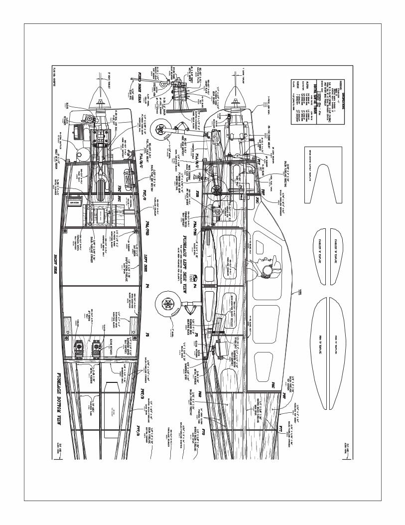
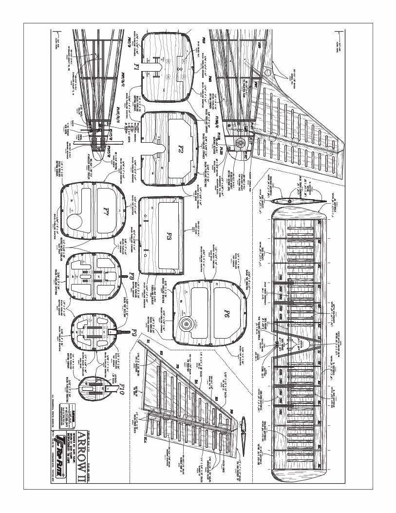
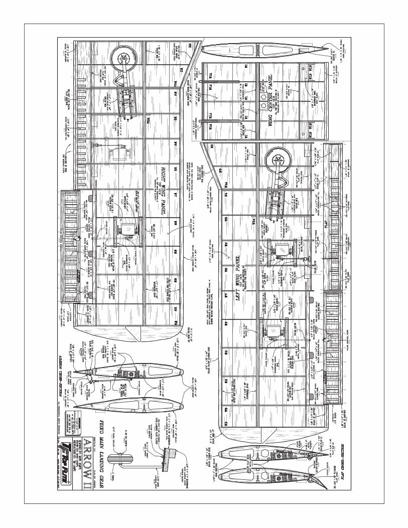
uselag
e/Win
g P
lan.........................center section
INT
RO
DU
CT
ION
Congratulations and thank you for purchasing the Top
Flite
®G
old Edition
Piper A
rrow II.
One of the unique
features of
this Top
Flite
Gold
kit is
the scale
corrugations on the vertical and horizontal stab and onall
of the
control surfaces.
The
corrugations are
optional, but add much to the scale effect of this m
odel.W
hile this
kit can
be assem
bled by
intermediate
builders, note that the corrugations take additional time,
skill and patience.Read through the m
anual to see howthe corrugations are m
ade and how they are covered
before making a decision.
Should you decide not to
build your
Arrow
w
ith corrugated
control surfaces
simply
replace the
die-cut, corrugated
skins w
ithregular sheeting (not included).
Another
option is
to build
the plane
with
fixed or
retractable landing gear.T
his kit was designed to fit
Robart retracts, so should you decide to install another
brand any modifications required w
ould be up to you.
Flaps
are another
option.T
he m
anual is
primarily
“geared”tow
ard building
the A
rrow
with
flaps, but
instructions are also provided for building the model
without flaps.
Lastly, the cabin top is vacuum-form
ed from a clear,
PE
TG
plastic sheet.The w
indow outlines are m
oldedin.F
inishing the cabin top requires masking, sanding
and painting around the window
s.S
ince the cabintop is m
olded from P
ET
G, it m
ay be painted with Top
Flite LustreK
ote®.
The level of scale detail you w
ish to achieve is up toyou.S
imply by follow
ing the instructions you’ll end upw
ith a model that very m
uch represents a Piper A
rrowII.B
ut you could also “go all-out”by adding even m
orescale
details to
make
a m
odel that
would
be a
contender in any level of scale competition.
For the latest technical updates or manual corrections
to the
Piper
Arrow
visit
the Top F
lite w
eb site
atw
ww
.top-flite.com.
Open
the “A
irplanes”link,
thenselect
the P
iper A
rrow.
If there
is new
technical
information or changes to this m
odel a “tech notice”boxw
ill appear in the upper left corner of the page.- 2
-
AM
AW
e urge you to join the AM
A (A
cademy of M
odelA
eronautics) and a local R/C
club.The A
MA
is thegoverning body of m
odel aviation and mem
bershipis required to fly at A
MA
clubs.Though joining the
AM
A provides m
any benefits, one of the primary
reasons to join is liability protection.Coverage is not
limited to flying at contests or on the club field.
Iteven applies to flying at public dem
onstrations andair show
s.Failure to com
ply with the S
afety Code
(excerpts printed in the back of the manual) m
ayendanger insurance coverage.
Additionally, training
programs and instructors are available at A
MA
clubsites to help you get started the right w
ay.There are
over 2,500 AM
A chartered clubs across the country.
Contact the A
MA
at the address or toll-free phonenum
ber below:
Acad
emy o
f Mo
del A
eron
autics
5151 East M
emorial D
riveM
uncie, IN 47302-9252
Tele.(800) 435-9262Fax (765) 741-0057
Or via the Internet at:http://w
ww
.modelaircraft.org
IMP
OR
TAN
T!!!
Two of the m
ost important things you can do to
preserve the radio controlled aircraft hobby are toavoid flying near full-scale aircraft and avoid flyingnear or over groups of people.
IMA
A
The Top F
lite Piper A
rrow II is an excellent scale
model and is eligible to fly in IM
AA
events.The IM
AA
(International Miniature A
ircraft Association) is an
organization that promotes non-com
petitive flying ofgiant-scale m
odels.If you plan to attend an IM
AA
event, obtain a copy of theIM
AA
Safety C
od
eby
contacting the IMA
Aat the address or telephone
number below
, or by logging on to their web site at:
ww
w.fly-im
aa.org/imaa/sanction.htm
l
IMA
A205 S
.Hilld
ale Ro
adS
alina,K
S 67401
(913) 823-5569
Scale C
om
petitio
nT
he outline of this Top Flite G
old Edition P
iper Arrow
II was derived from
three-view draw
ings and photos.T
he scale
is 1:4.6
which
was
calculated from
averaging the scale wingspan and the scale length.
Though the Top F
liteP
iper Arrow
II may not have the
same
level of
detail as
an “all-out”
scratch-builtcom
petition model, it is still a relatively detailed scale
model and is therefore ideal for com
peting in R/C
Sport S
cale (Sportsm
an and Expert), R
/C F
un Scale
(Division 1 or D
ivision 2), or even the Team S
caleclasses
in A
MA
com
petition (w
e receive
many
favorable reports
of Top
Flite
models
in scale
competition!).In F
un Scale, to receive the five points
for scale documentation, the only proof required that
a full
size aircraft
of this
type did
exist in
yourpaint/m
arkings scheme is a single sheet such as a
kit box cover from a plastic m
odel, a photo, or aprofile painting, etc.If the photo is in black and w
hiteother
written
documentation
of color
must
beprovided.
Contact the A
MA
for a rule book with full
details.No
te:T
he propeller on the model on the kit
box cover is oversize for the engine, but provides ascale appearance.
It is a Master A
irscrew 13 x 8
three-blade (MA
SQ
1938).The m
odel could actuallybe flow
n with a three-blade prop, but it m
ust be thecorrect size to m
atch your engine.
If you would like photos of the full-size P
iper Arrow
for scale documentation, or if you w
ould like to studythe photos to add m
ore scale details, photo packsare available from
:
Bob’s A
ircraft Docum
entation3114 Yukon A
veC
osta Mesa, C
A 92626
Telephone:(714) 979-8058Fax:(714) 979-7279
e-mail:w
ww
.bobsairdoc.com
1.Your P
iper Arrow
should not be considered a toy,but
rather a
sophisticated, w
orking m
odel that
fun
ction
s very
mu
ch
like
a
full-size
a
irpla
ne.
Because of its perform
ance capabilities, the Piper
Arrow
, if
not assem
bled and
operated correctly,
could possibly cause injury to yourself or spectatorsand dam
age to property.
2.You m
ust assemble the m
odel accord
ing
to th
ein
structio
ns.
Do not alter or m
odify the model, as
doing so may result in an unsafe or unflyable m
odel.In a few
cases the instructions may differ slightly
from
the photos.
In those
instances the
written
instructions should be considered as correct.
3.You must take tim
e to build straight,trueand strong.
4.You m
ust use an R/C
radio system that is in first-
class condition, and a correctly sized engine andcom
ponents (fuel tank, wheels, etc.) throughout the
building process.
5.You
must
correctly install
all R
/C
and other
components so that the m
odel operates correctly onthe ground and in the air.
6.You m
ust check the operation of the model before
everyflight to insure that all equipm
ent is operating andthat the m
odel has remained structurally sound.
Be
sure to check clevises or other connectors often andreplace them
if they show any signs of w
ear or fatigue.
7.If you are not an experienced pilot or have not
flown this type of m
odel before, we recom
mend that
you get the assistance of an experienced pilot inyour R
/C club for your first flights.
If you’re not am
ember
of a
club, your
local hobby
shop has
PR
OT
EC
T Y
OU
R M
OD
EL
,Y
OU
RS
EL
F &
OT
HE
RS
FO
LL
OW
TH
ES
E IM
PO
RTA
NT
SA
FE
TY
PR
EC
AU
TIO
NS
- 3-
- 4-
info
rma
tion
a
bo
ut
club
s in
yo
ur
are
a
wh
ose
mem
bership includes experienced pilots.
8.W
hile this kit has been flight tested to exceednorm
al use, if the plane will be used for extrem
elyhigh stress flying, such as racing, or if an enginelarger than one in the recom
mended range is used,
the m
odeler is
responsible for
taking steps
toreinforce the high stress points and/or substitutinghardw
are more suitable for the increased stress.
Rem
emb
er:Take
you
r tim
e an
d
follo
w
the
instru
ction
s to en
d u
p w
ith a w
ell-built m
od
elth
at is straigh
t and
true.
Before starting to build, com
pare the parts in this kitw
ith the Parts List and die draw
ings and note anym
issing parts.A
lso inspect all parts to make sure
they are
of acceptable
quality.If
any parts
arem
issing, broken or defective, or if you have anyquestions
about building
or flying
this airplane,
please contact Top Flite at the address or telephone
number
below.
If requesting
replacement
parts,please
provide the
full kit
name
(Top F
lite G
oldE
dition Piper A
rrow) and the part num
bers as listedin the P
arts List.
Top Flite P
roduct Support
3002 N A
pollo Drive S
uite 1C
hampaign, IL 61822
Telephone:(217) 398-8970Fax:(217) 398-7721
E-m
.
DE
CIS
ION
S Y
OU
MU
ST
MA
KE
This is a partial list of item
s required to finish theP
iper Arrow
that may require planning or decision
making before starting to build.
Order num
bers areprovided in parentheses.
RA
DIO
EQ
UIP
ME
NT
Even
though the
Piper
Arrow
is
giant-scale, it’s
basically a “.60-size”m
odel.T
herefore, the Arrow
doesn’t require any specialized, heavy-duty radiogear.It m
ay be flown safely w
ith standard servos onall of the flying surfaces excep
tfor the full-flying
stabilizer.T
he stabilizer should be controlled by aball bearing servo w
ith at least 50 oz.-in.of torque.
Servo
extensions and
Y-harnesses w
ill also
berequired.F
ollowing is a list of servos and other gear
used to
build the
Piper
Arrow
as
shown
in this
manual.
If you set up your model differently, other
radio gear may be required.
No
te:A
ll of the partnum
bers provided for R/C
gear are for Fu
taba. ®
❏(1) S
tabilizer servo with at least 50 oz.-in.of
torque (Futaba S
9001 or similar—
FU
TM
0075)❏
(5) Standard servos (1-nose w
heel steering, 1-throttle, 2-ailerons, 1-rudder)
❏(2) H
obbico 24"[610mm
] servo extensions (forailerons—
HC
AM
2721)❏
(3) Hobbico 12"[305m
m] servo extensions (for
stabilizer and rudder servos and coming from
receiver to hook up ailerons —H
CA
M2711)
❏(1) F
utaba dual extension cord (for ailerons—F
UT
M4130)
A G
reat Planes S
witch &
Charge Jack M
ounting Set
was also used (G
PM
M1000)
Th
e fo
llow
ing
item
s w
ill also
b
e req
uired
if
build
ing
op
tion
al flaps:
❏(2) S
tandard servos❏
(1) Hobbico Y-harness (H
CA
M2751)
❏(1) 12"[305m
m] servo extension (from
receiverto flap Y-harness—
HC
AM
2711)
If in
stalling
retractab
le lan
din
g
gear
this
add
ition
al radio
equ
ipm
ent w
ill also b
e requ
ired.
❏(1) M
icro servo❏
(1) 6"[150mm
] servo extension (HC
AM
2701)
A receiver battery pack w
ith a minim
umof 1,000m
Ah
is also required.(Futaba H
R4R
B, F
UT
M1380)
EN
GIN
E R
EC
OM
ME
ND
AT
ION
ST
he engine size recomm
endations for the Piper A
rroware straightforw
ard.See the recom
mendations on the
cover of this manual.K
eep in mind that this is a scale
model of a four-seat, general aviation aircraft, not an
aerobatic air show plane.It is intended to fly “on the
wing”
and will do so easily
with a .61 tw
o-stroke or a.91 four-stroke.D
o not overpower this aircraft.If using
an O.S
. ®M
ax SF
or SX
engine the Top Flite in-cow
lm
uffler may be used:
❏TO
PQ
7920 Top Flite header for in-cow
l muffler
(For O
.S.M
ax engines)❏
TOP
Q7917 Top F
lite In-cowl m
uffler
LA
ND
ING
GE
AR
OP
TIO
NS
The P
iper Arrow
requires two 3"[75m
m] m
ain wheels
and one 2-1/2"[64mm
] nose wheel.
If building theA
rrow
with
fixed landing
gear, any
brand of
theappropriate-size w
heels is suitable.W
ith retracts,R
obart wheels are recom
mended as they are narrow
and fit better into the wing.
Note that a R
obart 2-1/4"[57m
m] nose w
heel is recomm
ended as it will fit
on the nose strut better than a 2-1/2"[64mm
] wheel
(the Robart 2-1/4"[57m
m] w
heel is actually closer to2-3/8"[60m
m], so it is only 1/8"[3m
m] sm
aller thanrecom
mended).
Follow
ing are the part numbers for
the recomm
ended wheels:
❏G
reat Planes 3"[75m
m] m
ain wheels
(GP
MQ
4225)❏
Great P
lanes 2-1/2"[64mm
] nose wheel
(GP
MQ
4223)-or-
❏R
obart 3"[75mm
] main w
heels (RO
BQ
1514)❏
Robart 2-1/4"[57m
m] nose w
heel (RO
BQ
1511)
NO
TE
:W
e, as the kit manufacturer, provide you
with a top quality kit and great instructions, but
ultimately the quality and flyability of your finished
model depends on how
you build it;therefore, we
cannot in any way guarantee the perform
ance ofyour com
pleted model, and no representations
are expressed or implied as to the perform
ance orsafety of your com
pleted model.
Th
e follo
win
g item
s were also
used
to assem
ble
the P
iper A
rrow
with
retractable lan
din
g g
ear:
❏R
obart #530AR
W pneum
atic retractablelanding gear kit for P
iper Arrow
(RO
BQ
1621)❏
Robart #188V
R variable rate air control kit
(RO
BQ
2302, includes air tank, variable ratevalve, lines, fittings)
❏(1 pkg.) R
obart #190 Air Line Q
uickD
isconnects (RO
BQ
2395)❏
Robart hand pum
p with gauge (or suitable
replacement) (R
OB
Q2363)
❏M
icro servo and 6"[150mm
] servo extension(previously listed under “R
adio Equipm
ent”)❏
(2 pkgs.) Great P
lanes 0-80 (1/16”) threadedball link ball (G
PM
Q3842)
❏O
ptional:3/4 oz.[20g] glass cloth to reinforcew
ing sheeting inside wheel w
ells (HC
AR
5000)
CO
CK
PIT
AN
D P
ILO
TS
A scale cockpit kit is also available for this m
odel(TO
PQ
8414).It includes the floor, sides and back,
instrument panel, dashboard and four seats.
Even
though the cockpit kit can’t be seen in great detailunless
you are
up close
or have
the cabin
toprem
oved, it adds MU
CH
to the overall scale effecta
nd
re
ally
“finish
es”
the
m
od
el.
Insta
llatio
ninstructions are also included w
ith the cockpit kit.Tw
o William
s Brother’s #62600 S
portsman 3"[75m
m]
(1/4-scale) pilots (WB
RQ
2626) were used.S
ince thepilots are not full-body, a platform
was m
ade from3/32"[2.4m
m]
hard balsa
to support
them.
Acrylic
paint found at craft stores and hobby shops was used
for painting the pilots.Acrylic paint is favored because
it is easy to use and washes w
ith water.
TR
IM S
CH
EM
E/F
INIS
HIN
G S
UP
PL
IES
The trim
scheme on the m
odel on the kit box coverw
as inspired by a full-size Piper A
rrow.
All of the
wo
od
su
rface
s w
ere
cove
red
w
ith
Top
F
liteM
onoKote
®.The cabin top, cow
l and tail cone were
painted with Top F
lite LustreKote
®.Modelers w
ho areexperienced in the application of iron-on coveringsw
ill find this trim schem
e of medium
difficulty.If a
simpler or different trim
scheme is desired this one
could be used as a reference, or just follow the trim
scheme of another full-size subject.
Follow
ing arethe part num
bers of the MonoK
ote, LustreKote and
covering tools used.
CO
VE
RIN
G❏
(2) 6’[1.8m] rolls W
hite MonoK
ote (TOP
Q0204)
❏(1) 6’[1.8m
] roll Metallic red M
onoKote
(TOP
Q0405)
❏(1) 6’[1.8m
] roll Metallic gold M
onoKote
(TOP
Q0404)
PAIN
T❏
(2) White prim
er LustreKote (TO
PR
7801)❏
(1) Jet White LustreK
ote (TOP
R7204)
❏(1) M
etallic red LustreKote (TO
PR
7405)❏
(1) Crystal clear-gloss LustreK
ote (TOP
R7200)
❏1 roll of 1/4"[6.4m
m] M
etallic gold striping tape was
also used on the cowl and tail cone (G
PM
Q1530)
CO
VE
RIN
G TO
OL
S❏
Top Flite M
onoKote trim
seal iron (TOP
R2200)
❏21 st
Century sealing iron (C
OV
R2700)
❏21 st
Century iron cover (C
OV
R2702)
AD
DIT
ION
AL
ITE
MS
RE
QU
IRE
DH
AR
DW
AR
E A
ND
AC
CE
SS
OR
IES
In addition to the items listed in the “D
ecision
s You
Mu
st Make”
section, following is the list of hardw
areand accessories required to finish the P
iper Arrow
.O
rder numbers are provided in parentheses.
❏P
ropeller and spare propellers suitable for your engine
❏14 oz.[420cc] fuel tank (G
PM
Q4106)
❏F
uel line (3’[910mm
], GP
MQ
4131)❏
2-1/2"[65mm
] spinner (white-G
PM
Q4520, black-
GP
MQ
4521, red-GP
MQ
4522)-or-
❏T
hree-blade aluminum
True Turn spinner(T
RU
Q2514)
❏A
crylic paint and paint brushes for painting pilot(found at craft stores)
❏A
uto body filler (Bondo or sim
ilar)❏
R/C
foam padding (1/4"[6m
m] H
CA
Q1000,
1/2"[13mm
] HC
AQ
1050)❏
Sullivan #521 K
evlar pull-pull control cable set(for nose w
heel steering, SU
LQ3121)
❏If building flaps:(1 pkg.of 6) R
obart Super
Hinge P
oints (RO
BQ
2509)
AD
HE
SIV
ES
AN
D B
UIL
DIN
G S
UP
PL
IES
In addition to comm
on modeling tools (screw
drivers,hobby knives, drill, etc.), this is the “short list”
of them
ost important item
s required to build the Piper
Arrow
.We recom
mend G
reat Plan
es Pro
™ C
A and
Epoxy glue.
❏2 oz.[60g] T
hin Pro C
A (G
PM
R6003)
❏2 oz.[60g] M
edium P
ro CA
+ (G
PM
R6009)
❏1/2 oz.[15g] T
hick Pro C
A- (G
PM
R6013)
❏P
ro 30-minute epoxy (G
PM
R6047)
❏P
ro 6-minute epoxy (G
PM
R6045)
❏P
ro Aliphatic resin (2 oz.[60g], G
PM
R6160)
❏N
HP
balsa filler (NH
PR
2211)❏
Plan protector (G
PM
R6167) or w
ax paper❏
Drill bits:1/16"[1.6m
m], 5/64"[2m
m],
3/32"[2.4mm
], 7/64"[2.8mm
], 1/8"[3.2mm
],9/64"[3.6m
m], 5/32"[4m
m], 11/64"[4.4m
m],
3/16"[4.8mm
], 13/64"[5.2mm
], 7/32"[5.6mm
],15/64 [6m
m], 1/4"[6.4m
m], 17/64"[6.7m
m],
9/32"[7.1mm
]❏
8-32 tap and drill set (GP
MR
8103)❏
1/4-20 tap and drill set (GP
MR
8105)❏
Tap handle (GP
MR
8120)❏
Sm
all metal file
❏S
tick-on segmented lead w
eights (GP
MQ
4485)❏
Silver solder w
/flux (GP
MR
8070)❏
#1 Hobby knife (H
CA
R0105)
❏#11 blades (100-pack, H
CA
R0311)
- 5-
❏S
ingle-edge razor blades (100-pack, HC
AR
0312)❏
Sm
all T-pins (100, HC
AR
5100)❏
Medium
T-pins (100, HC
AR
5150)❏
Large T-pins (100, HC
AR
5200)❏
Sanding tools and sandpaper assortm
ent (seeE
asy-Touch Bar S
ander section)❏
16"x 48"[410 x 1220mm
] Great P
lanes Pro
Building B
oard (GP
MR
6950)❏
Curved-tip canopy scissors for trim
ming plastic
parts (HC
AR
0667)
OP
TIO
NA
L S
UP
PL
IES
AN
D TO
OL
SH
ere is a list of optional tools mentioned in the
manual that w
ill help you build the Piper A
rrow.
❏2 oz.[57g] spray C
A activator (G
PM
R6035)
❏4 oz.[113g] aerosol C
A activator (G
PM
R634)
❏C
A applicator tips (H
CA
R3780)
❏C
A debonder (G
PM
R6039)
❏3M
75 repositionable spray adhesive(M
MM
R1900)
❏K
yosho®
masking film
(KY
OR
1040)❏
Epoxy brushes (6, G
PM
R8060)
❏M
ixing sticks (50, GP
MR
8055)❏
Mixing cups (G
PM
R8056)
❏B
uilder’s Triangle Set (H
CA
R0480)
❏M
etal Template S
et (30/60/90 and 45 degreetriangles, H
CA
R0500)
❏36"m
etal ruler (HC
AR
0475)❏
Robart S
uper Stand II (R
OB
P1402)
❏24"x 36"[460 x 910m
m] B
uilder’s Cutting M
at(H
CA
R0456)
❏16"x 48"[410 x 1220m
m] building board
(GP
MR
6950)❏
Fuel filler valve for glow
fuel (GP
MQ
4160)❏
Hobbico D
uster ™can of com
pressed air (HC
AR
5500)❏
Masking tape (TO
PR
8018)❏
Milled fiberglass (G
PM
R6165)
❏M
icroballoons (TOP
R1090)
❏T
hreadlocker thread locking cement
(GP
MR
6060)❏
Denatured alcohol (for epoxy clean up)
❏K
& S
#801 Kevlar thread (for stab alignm
ent)❏
Panel Line P
en (TOP
Q2510)
❏R
otary tool such as Drem
el❏
Rotary tool reinforced cut-off w
heel (GP
MR
8200)❏
Servo horn drill (H
CA
R0698)
❏H
obby Heat ™
Micro Torch II (H
CA
R0755)
❏D
ead Center
™E
ngine Mount H
ole Locator(G
PM
R8130)
❏A
ccuThrow
™D
eflection Gauge (G
PM
R2405)
❏P
recision Hinge M
arking Tool (GP
MR
4005)❏
Slot M
achine™
hinge slotting tool (110V, GP
MR
4010) ❏
CG
Machine™
(GP
MR
2400)❏
Laser incidence meter (G
PM
R4020)
❏P
recision Magnetic P
rop Balancer
™
(TOP
Q5700)
EA
SY
-TOU
CH
™B
AR
SA
ND
ER
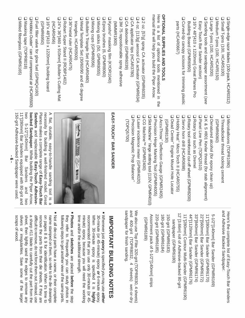
A
flat, durable,
easy-to-handle sanding
tool is
anecessity for building a w
ell-finished model.
Great
Planes m
akes a complete range of E
asy-Tou
ch B
arS
and
ersand replaceable E
asy-Tou
ch A
dh
esive-b
acked S
and
pap
er.While building the P
iper Arrow
,tw
o
5-1
/2"[1
40
mm
]B
ar
Sa
nd
ers
an
d
two
11"[280mm
] Bar S
anders equipped with 80-grit and
150-grit Adhesive-backed S
andpaper were used.
Here’s the com
plete list of Easy-Touch B
ar Sanders
and Adhesive B
acked Sandpaper:
5-1/2"[140mm
] Bar S
ander (GP
MR
6169)11"[280m
m] B
ar Sander (G
PM
R6170)
22"[560mm
] Bar S
ander (GP
MR
6172)33"[840m
m] B
ar Sander (G
PM
R6174)
44"[1120mm
] Bar S
ander (GP
MR
6176)11"[280m
m] C
ontour Multi-S
ander (GP
MR
6190)12’[3.66m
] roll of Adhesive-backed 80-grit
sandpaper (GP
MR
6180)150-grit (G
PM
R6183)
180-grit (GP
MR
6184)220-grit (G
PM
R6185)
Assortm
ent pack of 5-1/2"[140mm
] strips(G
PM
R6189)
We also use Top F
lite 320-grit (TOP
R8030, 4 sheets)
and 400-grit
(TO
PR
8032, 4
sheets) w
et-or-drysandpaper for finish sanding.
IMP
OR
TAN
T B
UIL
DIN
G N
OT
ES
·W
henever just epoxyis specified you m
ay use either30-m
inute (or 45-minute) epoxy or
6-minute epoxy.
When
30-minute
epoxy is
specified it
is highly
recomm
ended that you use only 30-minute (or 45-
minute) epoxy, because you w
ill need the working
time and/or the additional strength.
·P
hotosand sketches
are placed beforethe step
they refer to.Frequently you can study photos in
following steps to get another view
of the same parts.
·N
ot all die-cut parts have a name, or their com
pletenam
e stamped on them
, so refer to the die drawings
on pages 8 & 9 for identification.W
hen it’s time to
remove the parts from
their die sheets, if they aredifficult to rem
ove, do not force them out.Instead, use
a sharp #11 blade to carefully cut the part from the
sheet, then lightly sand the edges to remove any
slivers or
irregularities.S
ave som
e of
the larger
scraps of wood.
- 6-
TY
PE
S O
F W
OO
D
BA
LS
A B
AS
SW
OO
D P
LYW
OO
D
CO
MM
ON
AB
BR
EV
IAT
ION
S
Fuse =
Fuselage
Stab =
Horizontal S
tabilizerF
in = V
ertical Fin
LE =
Leading Edge
TE
= Trailing E
dgeLG
= Landing G
ear" =
Inchesm
m =
millim
eters
Du
ring
co
nstru
ction
th
ere
w
ill b
e
several
occa
sion
s w
he
re
ep
oxy cle
anu
p
will
be
necessary.Instead of wasting w
hole paper towels,
stack three or four paper towels on top of each
other and cut them into sm
all squares.T
his will
conserve paper towels and the little squares are
easier to use.F
or epoxy clean up dampen the
squares with denatured alcohol.
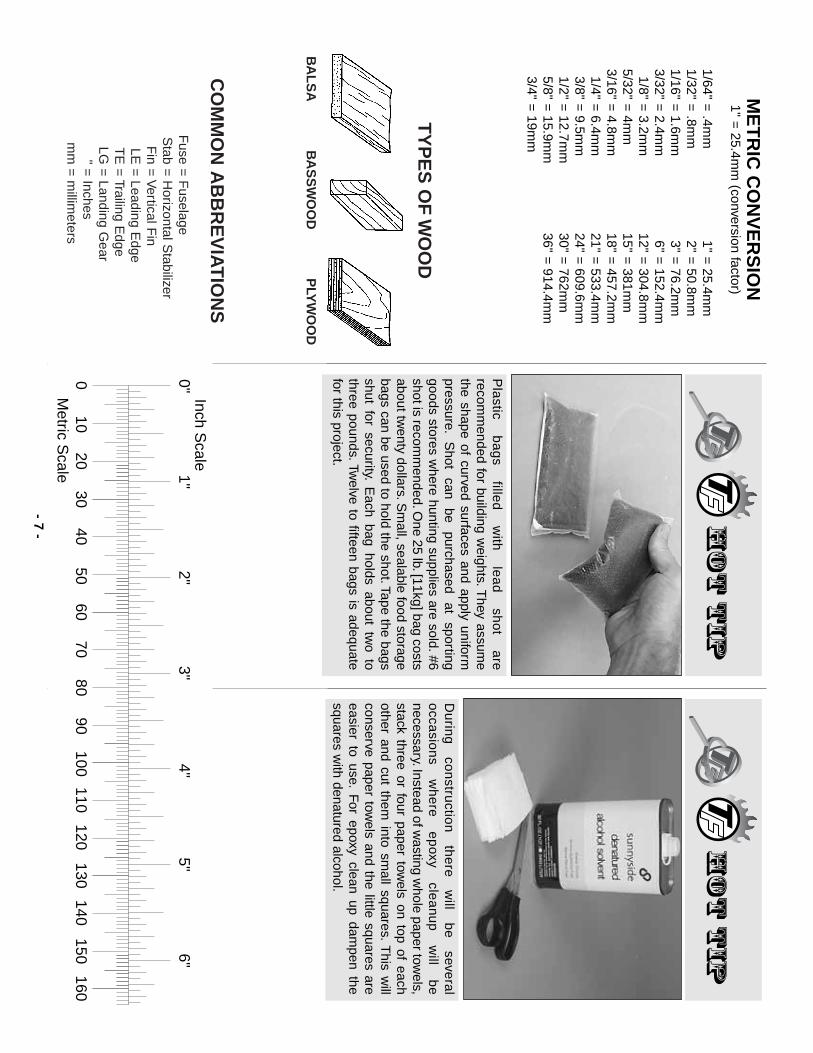
Pla
stic b
ag
s fille
d
with
le
ad
sh
ot
are
recomm
ended for building weights.T
hey assume
the shape of curved surfaces and apply uniformpressure.
Shot
can be
purchased at
sportinggoods stores w
here hunting supplies are sold.#6shot is recom
mended.O
ne 25 lb.[11kg] bag costsabout tw
enty dollars.Sm
all, sealable food storagebags can be used to hold the shot.Tape the bagsshut for security.
Each bag holds about tw
o tothree pounds.Tw
elve to fifteen bags is adequatefor this project.
1/64" = .4m
m1/32" =
.8mm
1/16" = 1.6m
m3/32" =
2.4mm
1/8" = 3.2m
m5/32" =
4mm
3/16" = 4.8m
m1/4" =
6.4mm
3/8" = 9.5m
m1/2" =
12.7mm
5/8" = 15.9m
m3/4" =
19mm
1" = 25.4m
m2" =
50.8mm
3" = 76.2m
m6" =
152.4mm
12" = 304.8m
m15" =
381mm
18" = 457.2m
m21" =
533.4mm
24" = 609.6m
m30" =
762mm
36" = 914.4m
m
ME
TR
IC C
ON
VE
RS
ION
1" = 25.4m
m (conversion factor)
- 7-
0"1"
2"3"
4"5"
6"
010
2030
4050
6070
8090
100110
120130
140150
160
Inch Scale
Metric S
cale
- 8-
DIE
-CU
T D
RA
WIN
GS

- 9-
DIE
-CU
T D
RA
WIN
GS
PR
EPA
RE
TO B
UIL
D
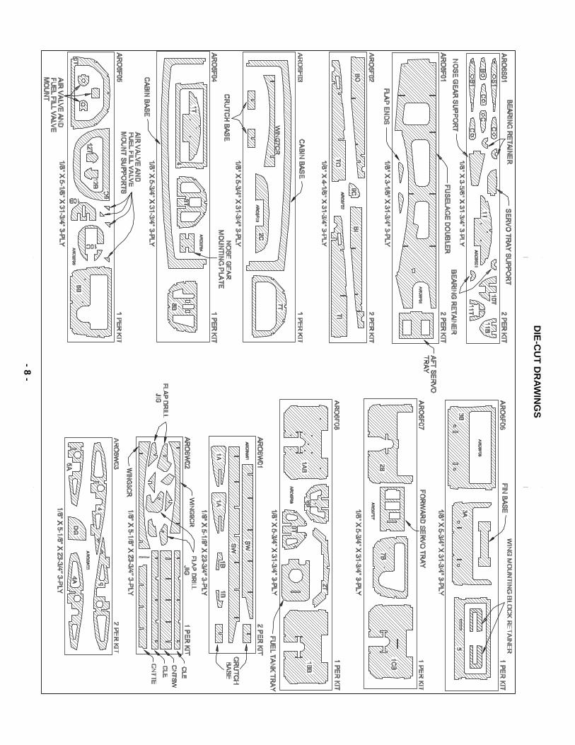
1.If you’ve already purchased the retractable landing
gear, or as soon as you do, take the air lines out of thepackage.U
nravel the lines and hang them som
ewhere
in your shop.When it’s tim
e to install the lines they’ll benice and straight and they’ll be easier to w
ork with.
2.R
emove all the parts from
the box.Use a ballpoint
pen (not a felt-tip pen) to lightly write the n
ame
orsize
on each piece so it can be identified later.Use
the die-cu
t pattern
son pages 8 &
9 to identify andm
ark the die-cut partsb
efore
removing them
fromtheir die sheets.
Many of the parts already have
numbers stam
ped on them, but in som
e cases thenum
bers are located beside the part or only on thedie draw
ings in the manual.
If a part is difficult torem
ove from its die sheet, don’t force it out.Instead,
cut around the part with a hobby knife and a #11
blade.After rem
oving the parts from their die sheets,
lightly sand
the edges
to rem
ove slivers
or die-
cuttin
g
irreg
ula
rities.
As
you
p
roce
ed
, it’s
no
tnecessary to save every scrap of w
ood, but some of
the larger pieces of wood should be saved.
3.S
eparate the parts into groups such as stab,fin
,w
ing
,and
fuse.
Store sm
aller parts in zipper-topfood storage bags.
BU
ILD
TH
E TA
IL S
UR
FAC
ES
BU
ILD
TH
E V
ER
TIC
AL
STA
BIL
IZE
R (F
IN)
❏1.
Unroll the fuselage plan, then re-roll it inside out
so it will lay flat.C
ut out the fin plan, then position it overyour flat building board and cover it w
ith Great P
lanesP
lan Protector or w
ax paper so glue will not adhere.
Note:
If you plan to build your Arrow
with any kind of a
scale lighting system, now
is the time to drill or cut any
holes in the ribs necessary to accomm
odate the wiring.
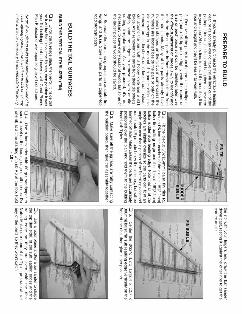
❏2.
Fit the die-cut 3/32"[2.4m
m] balsa fin ribs R
1through R
6into the notches of the die-cut 1/8"[3.2m
m]
balsa fin trailing edgeand the die-cut 1/8"[3.2m
m]
balsa rudder sub leading edge.N
ote that all of thenotches are slightly oversize so the parts can fit at anangle.A
lso note that a portion of the fin trailing edge andrudder sub LE
protrude below the assem
bly, but will be
trimm
ed off later.Make certain the parts are accurately
positioned over the plan and hold them to the building
board with T-pins.
❏3.
Make sure all the jig tabs are fu
llycontacting
the building board, then glue the assembly together.
❏4.
Use a bar sander w
ith 80-grit sandpaper tosand a bevel on the leading edge of all the ribs.D
oone rib at a tim
e starting with rib R
6 at the top.Hold
the rib with your fingers and draw
the bar sanderdow
n past, resting it against the other ribs to get thecorrect angle.
❏5.
Center
the 3/32"x
1/2"x 15"[2.4
x 12.7
x380m
m] balsa fin
sub
leadin
g ed
ge
vertically on thefront of the ribs, then glue it into position.
❏6.
Use a razor plane and/or a bar sander to shape
the top (left side) of the sub leading edges and thetra
iling
e
dg
e
so
they
are
eve
n
with
th
e
ribs.
No
te:M
ake sure none of the T-pins protrude aboveany of the parts so they w
on’t catch.- 10
-
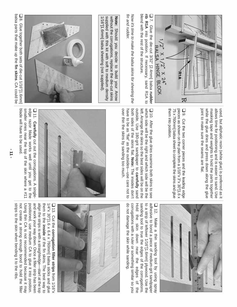
❏7.
Glue the die-cut 3/32”
[2.4mm
] balsa rud
der
rib R
1Ainto position.
If necessary, sand R1A
toblend w
ith the rest of the structure.
Now
it’s time to m
ake the balsa skins for sheeting thefin and rudder.
❏8.
Glue together both sets of die-cut 1/16"[1.6m
m]
balsa parts that make up the fin
skins.C
A could be
used, but aliphatic resin (white glue) is preferred as it
allows tim
e for positioning and is easier to sand.Use
masking tape and w
eights to hold the parts togetherw
hile the glue dries and press down along the glue
joint to make sure the seam
s are flat.
❏9.
Cut the tw
o corner pieces and the leading edgepieces as show
n on the plan from a 1/16"x 3"x 30"[1.6 x
75 x 760mm
] balsa sheet to complete the skins and glue
them into position.
❏10.
After the glue dries exam
ine both skins to seew
hich side will be the right and w
hich side will be the
left.Arrange the skins so the best sides w
ill be on theoutside.
Use 180-grit sandpaper to carefu
llysand
both sides of the skins flat.No
te:T
he insides don’thave to be as “flat”
as the outsides—use care not to
over thin the skins by sanding too much.
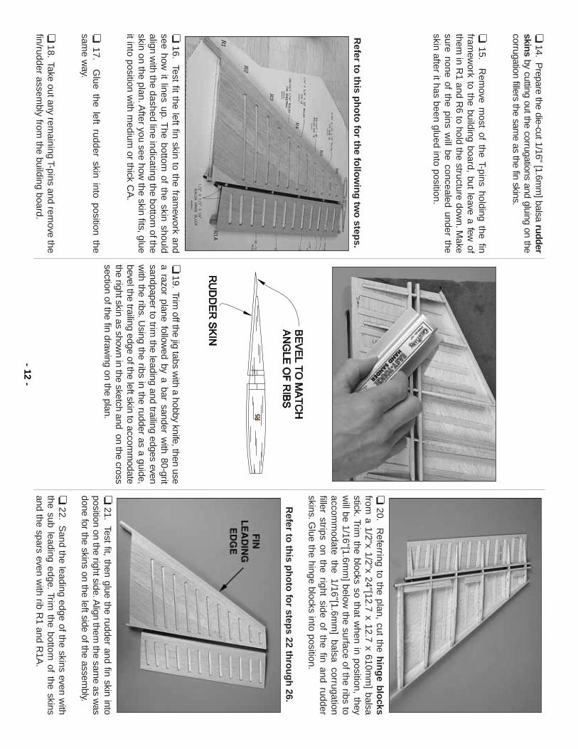
❏11.
Carefu
llycut out the corrugations.
A single-
edge razor blade works w
ell until you get to thesm
aller ones near the top of the skin where a #11
blade will have to be used.
❏12.
Make a thin sanding tool by using spray
adhesive to bond a piece of medium
-grit sandpaperto a strip of leftover 1/16"[1.6m
m] plyw
ood.U
se thesanding tool to true the edges of the corrugations.H
old
th
e
skin
dow
n
ne
ar
the
e
dg
es
of
the
corrugations with a ruler or som
ething similar so you
do not damage the skin w
hile sanding.
❏13.
Cut the co
rrug
ation
filler strips
from 1/16"x
1/4"x 30"[1.6 x 6.4 x 760mm
] balsa sticks and gluethem
to the insid
eof the fin skins.T
he best way to
align the strips is with a straightedge—
start at the topand w
ork your way dow
n.Once a filler strip has been
positioned, use medium
CA
to glue it into position.U
sing thin CA
is not recomm
ended because it may
not create a strong enough bond to hold the fillerstrips to the skin w
hen bending it to the ribs.
No
te:S
hould you
decide to
build your
Arrow
without the corrugations, replace the die-cut skins
supplied with this kit w
ith soft to medium
density1/16"[1.6m
m] balsa sheeting (not supplied).
- 11-
❏14.
Prepare the die-cut 1/16" [1.6m
m] balsa rudder
skinsby cutting out the corrugations and gluing on the
corrugation fillers the same as the fin skins.
❏15.
Rem
ove most of the T-pins holding the fin
framew
ork to the building board, but leave a few of
them in R
1 and R6 to hold the structure dow
n.Make
sure none of the pins will be concealed under the
skin after it has been glued into position.
Refer to
this p
ho
to fo
r the fo
llow
ing
two
steps.
❏16.
Test fit the left fin skin to the framew
ork andsee how
it lines up.T
he bottom of the skin should
align with the dashed line indicating the bottom
of theskin on the plan.A
fter you see how the skin fits, glue
it into position with m
edium or thick C
A.
❏17.
Glue the left rudder skin into position the
same w
ay.
❏18.
Take out any remaining T-pins and rem
ove thefin/rudder assem
bly from the building board.
❏19.
Trim off the jig tabs w
ith a hobby knife, then usea razor plane follow
ed by a bar sander with 80-grit
sandpaper to trim the leading and trailing edges even
with the ribs.U
sing the ribs in the rudder as a guide,bevel the trailing edge of the left skin to accom
modate
the right skin as shown in the sketch and on the cross
section of the fin drawing on the plan.
❏20.
Referring to the plan, cut the h
ing
e blo
cksfrom
a 1/2"x 1/2"x 24"[12.7 x 12.7 x 610mm
] balsastick.Trim
the blocks so that when in position, they
will be 1/16"[1.6m
m] below
the surface of the ribs toaccom
modate the 1/16"[1.6m
m] balsa corrugation
filler strips on the right side of the fin and rudderskins.G
lue the hinge blocks into position.
Refer to
this p
ho
to fo
r steps 22 th
rou
gh
26.
❏21.
Test fit, then glue the rudder and fin skin intoposition on the right side.A
lign them the sam
e as was
done for the skins on the left side of the assembly.
❏22.
Sand the leading edge of the skins even w
iththe sub leading edge.
Trim the bottom
of the skinsand the spars even w
ith rib R1 and R
1A.
- 12-
❏23.
Cut the fin
leadin
g ed
ge
from the 1/4"x 3/4"x
30"[6.4 x 19 x 760mm
] balsa stick, then glue it intoposition.
Save
the rem
ainder of
the stick
for the
rudder leading edge.Sand the top of the fin leading
edge even with R
6 and sand the sides of the leadingedge even w
ith both sides of the fin.
❏24.
Use a sm
all razor saw to separate the rudder
from the fin.S
and the fin sheeting and rib stubs evenw
ith the
fin trailing
edge and
sand the
ruddersheeting and the rib stubs even w
ith the rudder subleading edge.
❏25.
Cut the ru
dd
er leadin
g ed
ge
from rem
ainderof the 1/4"x 3/4"[6.4 x 19m
m] balsa stick used for the
fin leading edge, then glue it into position.Sand the
top, bottom and sides of the rudder leading edge
even with the rudder, but do not sand the “V
”on the
leading edge until instructed to do so.
FIN
ISH
TH
E F
IN A
ND
RU
DD
ER
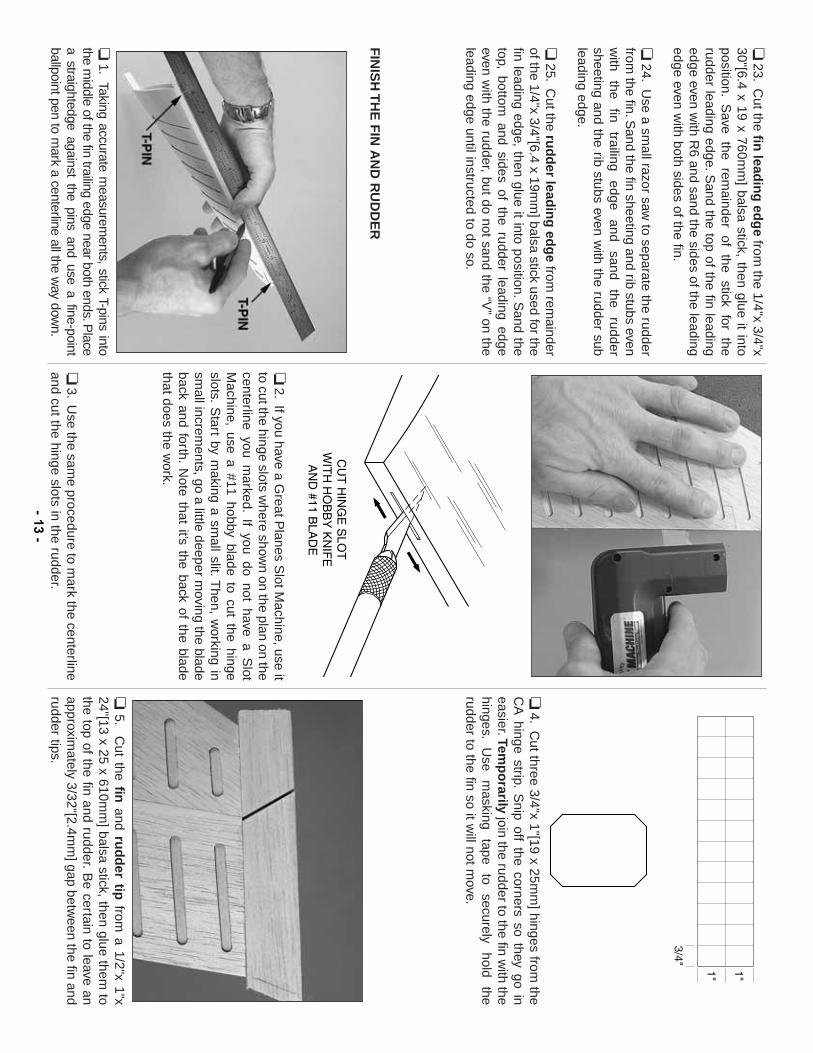
❏1.
Taking accurate measurem
ents, stick T-pins intothe m
iddle of the fin trailing edge near both ends.Place
a straightedge against the pins and use a fine-pointballpoint pen to m
ark a centerline all the way dow
n.
❏2.
If you have a Great P
lanes Slot M
achine, use itto cut the hinge slots w
here shown on the plan on the
centerline you marked.
If you do not have a Slot
Machine, use a #11 hobby blade to cut the hinge
slots.S
tart by making a sm
all slit.Then, w
orking insm
all increments, go a little deeper m
oving the bladeback and forth.
Note that it’s the back of the blade
that does the work.
❏3.
Use the sam
e procedure to mark the centerline
and cut the hinge slots in the rudder.
❏4.
Cut three 3/4"x 1"[19 x 25m
m] hinges from
theC
A hinge strip.
Snip off the corners so they go in
easier.Temp
orarily
join the rudder to the fin with the
hinges.U
se m
asking tape
to securely
hold the
rudder to the fin so it will not m
ove.
❏5.
Cut the fin
and rud
der tip
from a 1/2"x 1"x
24"[13 x 25 x 610mm
] balsa stick, then glue them to
the top of the fin and rudder.Be certain to leave an
approximately 3/32"[2.4m
m] gap betw
een the fin andrudder tips.
- 13-
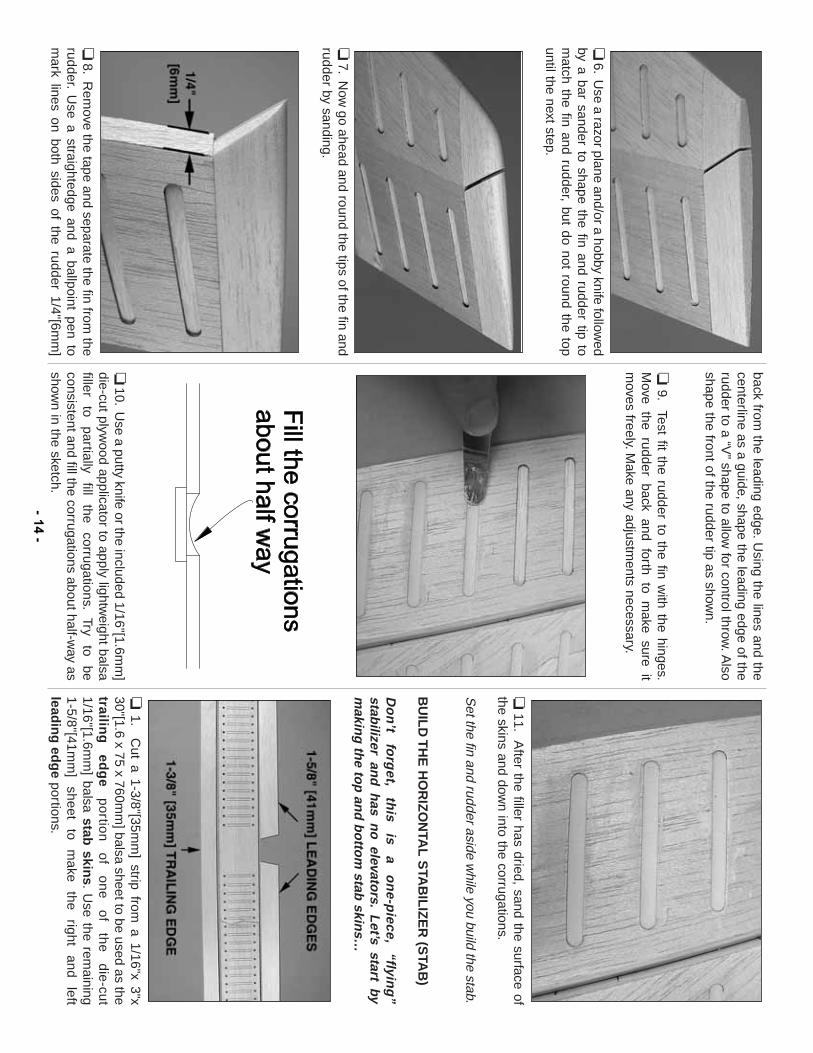
❏6.
Use a razor plane and/or a hobby knife follow
edby a bar sander to shape the fin and rudder tip tom
atch the fin and rudder, but do not round the topuntil the next step.
❏7.
Now
go ahead and round the tips of the fin andrudder by sanding.
❏8.
Rem
ove the tape and separate the fin from the
rudder.U
se a straightedge and a ballpoint pen tom
ark lines on both sides of the rudder 1/4"[6mm
]
back from the leading edge.U
sing the lines and thecenterline as a guide, shape the leading edge of therudder to a “V
”shape to allow
for control throw.A
lsoshape the front of the rudder tip as show
n.
❏9.
Test fit the rudder to the fin with the hinges.
Move the rudder back and forth to m
ake sure itm
oves freely.Make any adjustm
ents necessary.
❏10.
Use a putty knife or the included 1/16"[1.6m
m]
die-cut plywood applicator to apply lightw
eight balsafiller
to partially
fill the
corrugations.Try
to be
consistent and fill the corrugations about half-way as
shown in the sketch.
❏11.
After the filler has dried, sand the surface of
the skins and down into the corrugations.
Set the fin and rudder aside w
hile you build the stab.
BU
ILD
TH
E H
OR
IZO
NTA
L S
TAB
ILIZ
ER
(STA
B)
Do
n’t
forg
et,th
is is
a o
ne-p
iece,“flyin
g”
stabilizer an
d h
as no
elevators.
Let’s start by
makin
g th
e top
and
bo
ttom
stab skin
s…
❏1.
Cut a 1-3/8"[35m
m] strip from
a 1/16"x 3"x30"[1.6 x 75 x 760m
m] balsa sheet to be used as the
trailing
ed
ge
po
rtion
o
f o
ne
o
f th
e
die
-cut
1/16"[1.6mm
] balsa stab skin
s.U
se the remaining
1-5/8"[41mm
] sheet
to m
ake the
right and
leftlead
ing
edg
eportions.
- 14-
❏2.
Repeat the previous step to m
ake the leading andtrailing edge portions of the other stab skin.
Glue the
sheets you just cut to the front and back of the stabskins.R
eminder:A
liphatic resin is recomm
ended overC
A because it w
ill allow tim
e to position the sheets andw
ill be easier to sand after it dries.
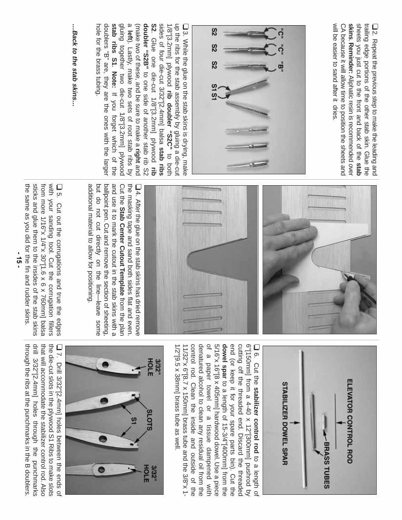
❏3.
While the glue on the stab skins is drying, m
akeup the ribs for the stab assem
bly by gluing a die-cut1/8"[3.2m
m]
plywood
rib
do
ub
ler “S2C
”to
bothsides of four die-cut 3/32"[2.4m
m] balsa stab
ribs
S2.
Glue
one die-cut
1/8"[3.2mm
] plyw
ood rib
do
ub
ler “S2B
”to one side of another stab rib S
2(m
ake two of these, and be sure to m
ake a righ
tand
a left).Lastly, m
ake two sets of root stab ribs by
gluing together
two
die-cut 1/8"[3.2m
m]
plywood
stab
ribs
S1.
No
te:If
you forget
which
of the
doublers “B”
are, they are the ones with the larger
hole for the brass tubing.
…B
ack to th
e stab skin
s…
❏4.
After the glue on the stab skins has dried rem
ovethe m
asking tape and sand both sides flat and even.C
ut the Stab
Cen
ter Cu
tou
t Temp
latefrom
the planand use it to m
ark the cutout in the stab skins with a
ballpoint pen.Cut and rem
ove the section of sheeting,but
do not
cut directly
on the
line—leave
some
additional material to allow
for positioning.
❏5.
Cut out the corrugations and true the edges
with your sanding tool.
Cut the corrugation fillers
from m
ore 1/16"x 1/4"x 30"[1.6 x 6 x 760mm
] balsasticks and glue them
to the insides of the stab skinsthe sam
e as you did for the fin and rudder skins.
❏6.
Cut the stab
ilizer con
trol ro
dto a length of
6"[150mm
] from a 4-40 x 12"[300m
m] pushrod by
cutting off the threaded end.D
iscard the threadedend (or keep it for your spare parts bin).
Cut the
do
wel sp
arto a length of 15-3/4"[400m
m] from
the5/16"x 16"[8 x 405m
m] hardw
ood dowel.U
se a pieceo
f a
p
ap
er
towe
l o
r a
tissu
e
da
mp
en
ed
w
ithdenatured alcohol to clean any residual oil from
thecontrol
rod.C
lean the
inside and
outside of
the11/32"x 6"[8.7 x 150m
m] brass tube and the 3/8"x 1-
1/2"[9.5 x 38mm
] brass tube as well.
❏7.
Drill 3/32"[2.4m
m] holes betw
een the ends ofthe die-cut slots in the plyw
ood S1 R
ibs to make slots
that will accom
modate the stabilizer control rod.A
lsodrill
3/32"[2.4mm
] holes
through the
punchmarks
through the ribs at the punchmarks in the B
doublers.- 15
-
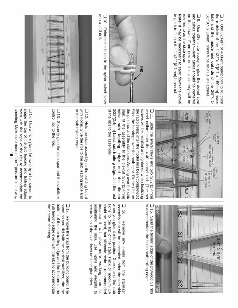
❏8.
Use 320-grit or 400-grit sandpaper to roughen
the ou
tside
of the 11/32"x 6"[8.7 x 150mm
] brasstube and the in
side
and ou
tside
of the 3/8"x 1-1/2"[9.5 x 38m
m] brass tube so glue w
ill adhere.
❏9.
Use 30-m
inute epoxy to glue the dowel spar
and tubes together—both tubes should be centered
on the dowel.
From now
on this assembly w
ill bereferred to as the stab
spar.
No
te:It m
ay be necessary to sand down the dow
elto get it to fit into the 11/32" [8.7m
m] brass tub.
❏10.
Enlarge the holes in the nylon sw
ivel clevisw
ith a #40 drill.
❏11.
Slide the sw
ivel clevis and two 3/32"[2.4m
m]
wheel collars onto the 4-40 control rod.
(The set
screws w
ill be installed and tightened when finalizing
the radio setup after the model has been com
pleted.)S
lide the bearings over the stab spar.Fit the ribs on
the pushrod and the stab spar.Working over the stab
plan, fit the assembly to the die-cut 3/32"[2.4m
m]
ba
lsa
sub
lead
ing
ed
ge
an
d
the
d
ie-cu
t3/32"[2.4m
m] balsa su
b trailin
g ed
ge.Join the rest
of the ribs to the assembly.
❏12.
Hold the stab assem
bly to the building boardw
ith T-pins.Glue the ribs to the sub leading edge and
to the sub trailing edge.
❏13.
Securely glue the stab spar and the stabilizer
control rod to the ribs.
❏14.
Use a razor plane follow
ed by a bar sander toshape the top of the sub leading and trailing edgeseven w
ith the tops of the ribs to accomm
odate thesheeting.M
ake sure none of the T-pins are in the way.
❏15.
Sand the trailing edge of the plyw
ood S1 ribs
to accomm
odate the balsa stab trailing edge.
❏16.
Rem
ove any
T-pins from
the
stabilizerassem
bly that will be concealed under the stab skin
when you glue it into position.
Glue one of the stab
skins to the top of the stab.T
hick or medium
CA
could be used, but aliphatic resin is recomm
endedb
eca
use
it
will
allow
m
ore
w
orking
tim
e
forpositioning
the skin.
Use
T-pins and
weights
tosecurely hold the skin dow
n until the glue dries.
❏17.
Rem
ove the stab from the building board.T
hesam
e as you did with the vertical stabilizer, trim
thebottom
of the sub trailing edge and the bottom of the
sub leading edge even with the ribs to accom
modate
the bottom sheeting.
- 16-
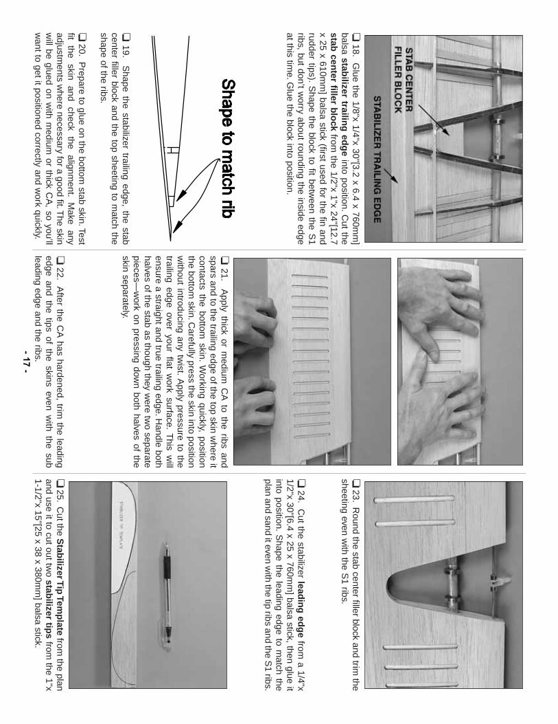
❏18.
Glue the 1/8"x 1/4"x 30"[3.2 x 6.4 x 760m
m]
balsa stabilizer trailin
g ed
ge
into position.C
ut thestab
center filler b
lock
from the 1/2"x 1"x 24"[12.7
x 25 x 610mm
] balsa stick (first used for the fin andrudder tips).
Shape the block to fit betw
een the S1
ribs, but don’t worry about rounding the inside edge
at this time.G
lue the block into position.
❏19.
Shape the stabilizer trailing edge, the stab
center filler block and the top sheeting to match the
shape of the ribs.
❏20.
Prepare to glue on the bottom
stab skin.Testfit
the skin
and check
the alignm
ent.M
ake any
adjustments w
here necessary for a good fit.The skin
will be glued on w
ith medium
or thick CA
, so you’llw
ant to get it positioned correctly and work quickly.
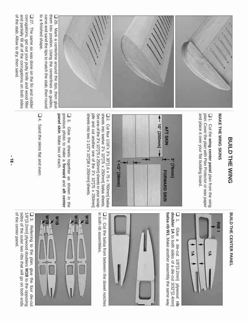
❏21.
Apply thick or m
edium C
A to the ribs and
spars and to the trailing edge of the top skin where it
contacts the bottom skin.
Working quickly, position
the bottom skin.C
arefully press the skin into positionw
ithout introducing any twist.
Apply pressure to the
trailing edge over your flat work surface.
This w
illensure a straight and true trailing edge.H
andle bothhalves of the stab as though they w
ere two separate
pieces—w
ork on pressing down both halves of the
skin separately.
❏22.
After the C
A has hardened, trim
the leadingedge and the tips of the skins even w
ith the subleading edge and the ribs.
❏23.
Round the stab center filler block and trim
thesheeting even w
ith the S1 ribs.
❏24.
Cut the stabilizer lead
ing
edg
efrom
a 1/4"x1/2"x 30"[6.4 x 25 x 760m
m] balsa stick, then glue it
into position.S
hape the leading edge to match the
plan and sand it even with the tip ribs and the S
1 ribs.
❏25.
Cut the S
tabilizer T
ip Tem
plate
from the plan
and use it to cut out two stab
ilizer tips
from the 1"x
1-1/2"x 15"[25 x 38 x 380mm
] balsa stick.- 17
-
❏26.
Mark a centerline around the tips, then glue
them into position.
Using the centerlines as guides,
carve and sand the tips to match the stab, then round
to a finished shape.
❏27.
The sam
e as was done on the fin and rudder
corrugations, get out your putty knife and wood filler
and partially fill all of the corrugations on both sidesof the stab.A
llow to dry, then sand.
BU
ILD
TH
E W
ING
MA
KE
TH
E W
ING
SK
INS
❏1.
Cut the w
ing
center p
anel
plan from the w
ingplan.C
over the plan with P
lan Protector or w
ax paperand place it over your flat building board.
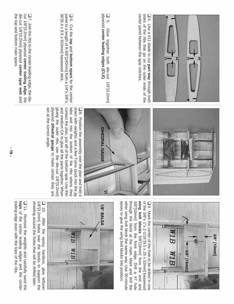
❏2.
Cut four 1/16"x 3"x 30"[1.6 x 75 x 760m
m] balsa
sheets into twelve 3"x 10"[75 x 250m
m] balsa sheets.
Set one of the 3"x 10"[75 x 250m
m] sheets in your scrap
pile and cut another one of the 3"x 10"[75 x 250mm
]sheets into tw
o 1-1/2"x 10"[38 x 250mm
] sheets.
❏3.
Glue the sheets together as show
n in theprevious photo to m
ake a forw
ardand aft cen
terp
anel skin
.Make tw
o of each.
❏4.
Sand the skins flat and even.
BU
ILD
TH
E C
EN
TE
R PA
NE
L
❏1.
Glue
a die-cut
1/8"[3.2mm
] plyw
ood rib
do
ub
ler 1Ato both sides of a die-cut 3/32"[2.4m
m]
balsa rib
W1.M
ake another assembly the sam
e way.
❏2.
Cut the balsa from
between the dow
el notchesin both rib assem
blies.
❏3.
Referring to the plan, glue the four die-cut
1/8"[3.2mm
] plywood doublers W
1Bto the opposing
sides of the outer two ribs that w
ill go on both endsof the center panel.
- 18-
❏4.
Use a #11 blade to cut p
art way
through bothsides of the ribs that go on the outer ends of thecenter panel betw
een the spar notches.
❏5.
Glue
together both
die-cut 1/8"[3.2m
m]
plywood cen
ter leadin
g ed
ges (C
LE
).
❏6.
Cut the to
pand b
otto
m sp
arsfor the center
panel to a length of 9-3/8"[240mm
] from a 1/4"x 3/8"x
36"[6.4 x 9.5 x 910mm
] basswood stick.
❏7.
Join the ribs to the center leading edge, the die-cut 1/8"[3.2m
m] plyw
ood center trailin
g ed
ge, the
die-cut 1/8"[3.2mm
] plywood cen
ter spar w
eband
the top and bottom m
ain spars.
❏8.
Position the assem
bly over the plan and hold itdow
n with w
eights and a few T-pins stuck into the jig
tabs and into the bottom of the ribs w
here theycontact the plan, just aft of the bottom
spar.Use thin
and medium
CA
to glue all the parts together.When
gluing the outer ribs, use the die-cut 1/8"[3.2mm
]plyw
ood dih
edral g
aug
eto m
ake certain they areset at the correct angle.
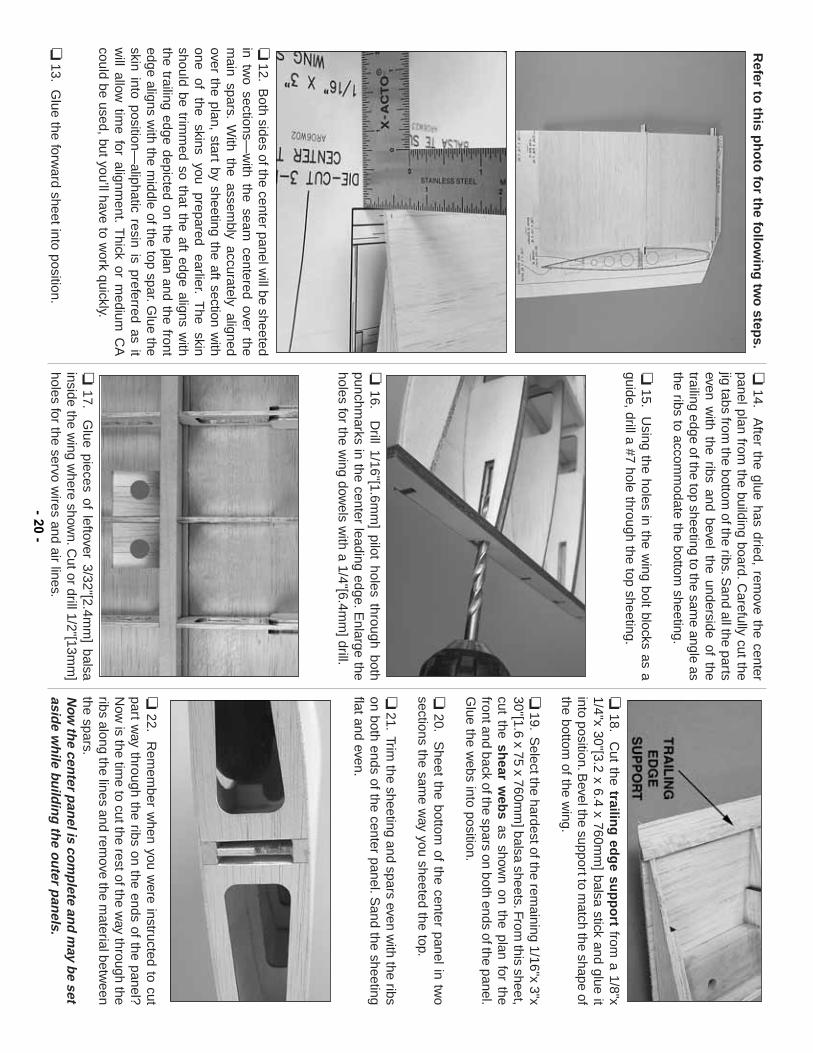
❏9.
Mark the center of the hole to be drilled in one
of the 3/8"x 1"x 2-1/16"[9.5 x 25 x 52mm
] basswood
win
g b
olt b
locks
5/8"[16mm
] from
the
end and
3/8"[10mm
] from
the
front edge.
Drill
a #7
holethrough the block at the m
ark.M
ark and drill theother w
ing bolt block the same w
ay.U
se 30-minute
epoxy to glue the wing bolt blocks into position.
❏10.
After
the epoxy
hardens, glue
leftover1/8"[3.2m
m] balsa over the blocks to support the
sheeting around the holes that will be drilled later.
❏11.
Rem
ove the weights and carefully sand the
top
sof the center leading edges and the center
trailing edge even with the tops of the ribs.
- 19-
Refer to
this p
ho
to fo
r the fo
llow
ing
two
steps.
❏12.
Both sides of the center panel w
ill be sheetedin tw
o sections—w
ith the seam centered over the
main spars.
With the assem
bly accurately alignedover the plan, start by sheeting the aft section w
ithone
of the
skins you
prepared earlier.
The
skinshould be trim
med so that the aft edge aligns w
iththe trailing edge depicted on the plan and the frontedge aligns w
ith the middle of the top spar.G
lue theskin into position—
aliphatic resin is preferred as itw
ill allow tim
e for alignment.
Thick or m
edium C
Acould be used, but you’ll have to w
ork quickly.
❏13.
Glue the forw
ard sheet into position.
❏14.
After the glue has dried, rem
ove the centerpanel plan from
the building board.Carefully cut the
jig tabs from the bottom
of the ribs.Sand all the parts
even with the ribs and bevel the underside of the
trailing edge of the top sheeting to the same angle as
the ribs to accomm
odate the bottom sheeting.
❏15.
Using the holes in the w
ing bolt blocks as aguide, drill a #7 hole through the top sheeting.
❏16.
Drill 1/16"[1.6m
m] pilot holes through both
punchmarks in the center leading edge.E
nlarge theholes for the w
ing dowels w
ith a 1/4"[6.4mm
] drill.
❏17.
Glue pieces of leftover 3/32"[2.4m
m] balsa
inside the wing w
here shown.C
ut or drill 1/2"[13mm
]holes for the servo w
ires and air lines.
❏18.
Cut the trailin
g ed
ge su
pp
ort
from a 1/8"x
1/4"x 30"[3.2 x 6.4 x 760mm
] balsa stick and glue itinto position.B
evel the support to match the shape of
the bottom of the w
ing.
❏19.
Select the hardest of the rem
aining 1/16"x 3"x30"[1.6 x 75 x 760m
m] balsa sheets.From
this sheet,cut the sh
ear web
sas show
n on the plan for thefront and back of the spars on both ends of the panel.G
lue the webs into position.
❏20.
Sheet the bottom
of the center panel in two
sections the same w
ay you sheeted the top.
❏21.
Trim the sheeting and spars even w
ith the ribson both ends of the center panel.S
and the sheetingflat and even.
❏22.
Rem
ember w
hen you were instructed to cut
part way through the ribs on the ends of the panel?
Now
is the time to cut the rest of the w
ay through theribs along the lines and rem
ove the material betw
eenthe spars.N
ow th
e center p
anel is co
mp
lete and
may b
e setasid
e wh
ile build
ing
the o
uter p
anels.
- 20-
BU
ILD
TH
E O
UT
ER
PAN
EL
S
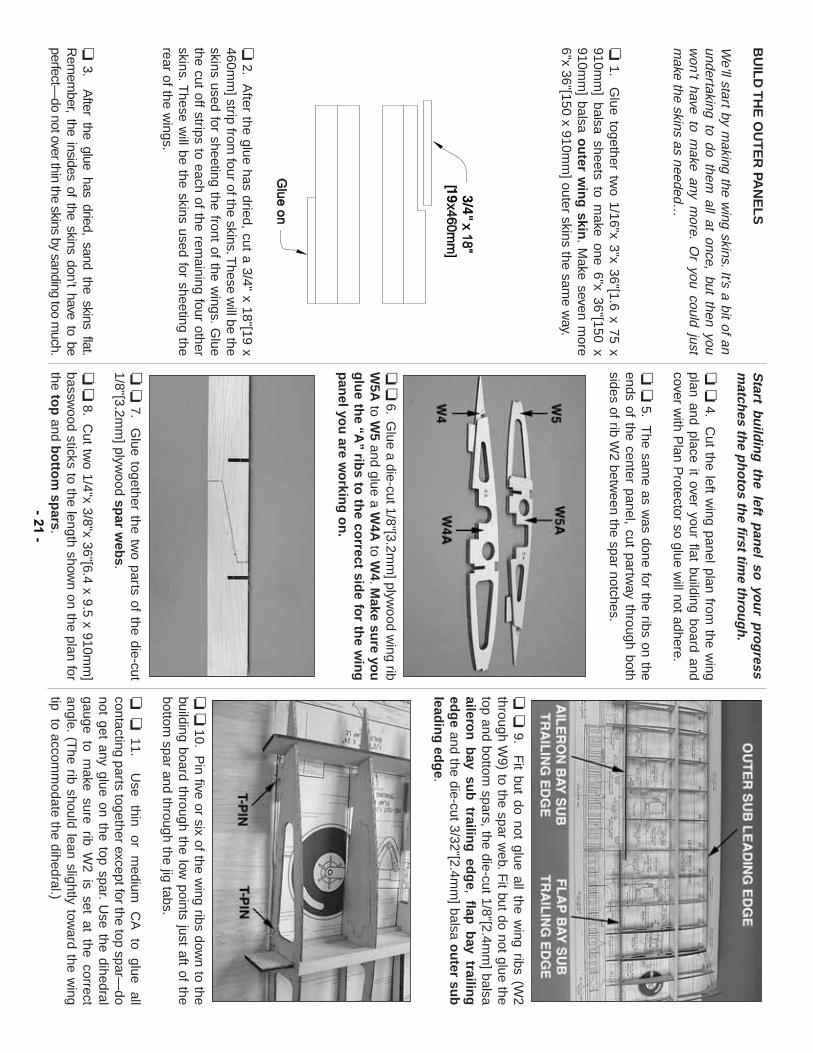
We’ll start by m
aking the wing skins.It’s a bit of an
undertaking to do them all at once, but then you
won’t have to m
ake any more.
Or you could just
make the skins as needed…
❏1.
Glue together tw
o 1/16"x 3"x 36"[1.6 x 75 x910m
m] balsa sheets to m
ake one 6"x 36"[150 x910m
m] balsa o
uter w
ing
skin.
Make seven m
ore6"x 36"[150 x 910m
m] outer skins the sam
e way.
❏2.
After the glue has dried, cut a 3/4" x 18"[19 x
460mm
] strip from four of the skins.T
hese will be the
skins used for sheeting the front of the wings.
Glue
the cut off strips to each of the remaining four other
skins.These w
ill be the skins used for sheeting therear of the w
ings.
❏3.
After the glue has dried, sand the skins flat.
Rem
ember, the insides of the skins don’t have to be
perfect—do not over thin the skins by sanding too m
uch.
Start bu
ildin
g th
e left pan
el so yo
ur p
rog
ressm
atches th
e ph
oto
s the first tim
e thro
ug
h.
❏❏
4.C
ut the left wing panel plan from
the wing
plan and place it over your flat building board andcover w
ith Plan P
rotector so glue will not adhere.
❏❏
5.T
he same as w
as done for the ribs on theends of the center panel, cut partw
ay through bothsides of rib W
2 between the spar notches.
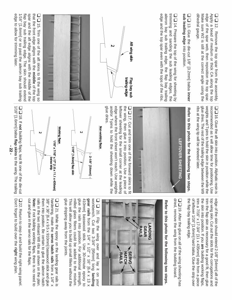
❏❏6.
Glue a die-cut 1/8"[3.2m
m] plyw
ood wing rib
W5A
to W5
and glue a W4A
to W4.M
ake sure yo
ug
lue th
e “A”
ribs to
the co
rrect side fo
r the w
ing
pan
el you
are wo
rking
on
.
❏❏
7.G
lue together the two parts of the die-cut
1/8"[3.2mm
] plywood sp
ar web
s.
❏❏
8.C
ut two 1/4"x 3/8"x 36"[6.4 x 9.5 x 910m
m]
basswood sticks to the length show
n on the plan forthe to
pand b
otto
m sp
ars.
❏❏
9.F
it but do not glue all the wing ribs (W
2through W
9) to the spar web.F
it but do not glue thetop and bottom
spars, the die-cut 1/8"[2.4mm
] balsaailero
n b
ay sub
trailing
edg
e, flap b
ay trailing
edg
eand the die-cut 3/32"[2.4m
m] balsa o
uter su
blead
ing
edg
e.
❏❏
10.P
in five or six of the wing ribs dow
n to thebuilding board through the low
points just aft of thebottom
spar and through the jig tabs.
❏❏
11.U
se thin
or m
edium
CA
to
glue all
contacting parts together except for the top spar—do
not get any glue on the top spar.U
se the dihedralgauge to m
ake sure rib W2 is set at the correct
angle.(T
he rib should lean slightly toward the w
ingtip to accom
modate the dihedral.)
- 21-
❏❏
12.R
emove the top spar from
the assembly.
Apply a bead of m
edium or thick C
A along the top
edge of the spar web, then reposition the top spar.
Make sure W
2 is still at the correct angle using thedihedral gauge.
❏❏
13.G
lue the die-cut 1/8" [3.2mm
] balsa inn
ersu
b lead
ing
edg
einto position.
❏❏
14.Prepare the top of the w
ing for sheeting bytrim
ming and sanding the sub leading edges, the
aileron bay sub trailing edge, the flap bay trailingedge and the top spar even w
ith the tops of the ribs.
❏❏
15.Trim one of the aft skins to fit the w
ing sothat the front edge aligns w
ith the mid
dle
of the topspar and the aft edge aligns w
ith the middle of the
flap bay sub trailing edge.T
he skin should extend1/16" [1.6m
m] or so past the aileron bay sub trailing
edge to allow for trim
ming later.
❏❏16.G
lue the aft skin into position.Aliphatic resin is
recomm
ended as it will allow
time for positioning.U
sew
eights and T-pins to hold the skin in position while the
glue dries.The rest of the trailing edge betw
een the W9
ribs at the wing tip w
ill be sheeted later.
Refer to
this p
ho
to fo
r the fo
llow
ing
two
steps.
❏❏
17.Cut and trim
one of the forward skins to fit
the wing, then glue it into position.
Use a piece of
leftover sheeting for the small corner at the leading
edge where the front sheet w
on’t reach.Use w
eightsand/or T-pins to hold the sheeting dow
n while the
glue dries.
❏❏
18.If notbuilding flaps, test fit one of the die-cut
1/16" [1.6mm
] balsa flap skinsto the w
ing.The trailing
edge of the skin should extend 2-1/8" [54mm
] aft of thetop w
ing skin.Cut out the slots for the corrugations and
trim the flap skin as necessary for a good fit, then glue
the skin into position.If you arebuilding w
orking flaps,trim
a 7/16" x 17-3/4" [11 x 435mm
] strip from a piece
of leftover 1/16" [1.6mm
] hard balsa.Glue the strip over
the flap bay trailing edge.
❏❏19.A
fter the glue on all of the wing sheeting has
dried, remove the w
ing from the building board.
Refer to
this p
ho
to fo
r the fo
llow
ing
two
steps.
❏❏
20.F
lip the
wing
over and
lay it
on your
workbench.
Cut
two
3-3/4" [95m
m]
long lan
din
gg
ear railsfrom
the 1/4" x 1/2" x 16" [6.4 x 13 x410m
m] bassw
ood stick.U
se 30-minute epoxy to
glue the rails into position.F
or additional strength,m
illed glass fibers could be added to the mixture.
This w
ill allow you to build up sm
all fillets without the
glue dripping away from
the joints.
❏❏
21.While the epoxy on the landing gear rails is
hardening, make the servo hatch rails
from a 1/4" x
3/8" x 36" [6.4 x 9.5 x 910mm
] basswood stick and glue
them into position.B
e certain to glue the aileron hatchrails in the tw
o inboard W8 ribs as show
n on the plan.N
ote:If not building w
orking flaps, there is no need tocut and glue in the servo rails for the flaps.
❏22.R
eturn to step 4 and build the right wing panel.
Don't forget to build over the rig
ht
wing plan.
- 22-
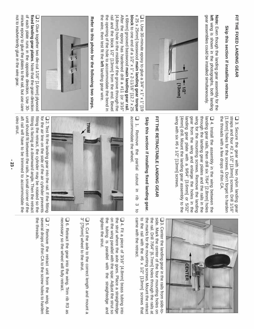
FIT
TH
E F
IXE
D L
AN
DIN
G G
EA
R
Skip
this sectio
n if in
stalling
retracts.
Note:
Even though the landing gear assem
bly for theleft
wing is show
n in the photographs, both landinggear assem
blies could be installed simultaneously.
❏1.U
se 30-minute epoxy to glue a 3/4" x 1" x 1" [19
x 25 x 25mm
] basswood m
ain lan
din
g g
ear torq
ue
blo
ckto one end of a 1/2" x 1" x 2-11/16" [12.7 x 25
x 68mm
] grooved basswood m
ain lan
din
g g
ear rail.A
fter the epoxy has hardened drill a #11 (or 3/16"[4.8m
m]) hole in the m
iddle of the groove through therail and the block 1/2" [13m
m] from
the end.B
evelthe opening of the hole to accom
modate the bend in
the wire, then test fit the left
landing gear wire.
Refer to
this p
ho
to fo
r the fo
llow
ing
two
steps.
❏2.G
lue together two die-cut 1/16" [1.6m
m] plyw
oodfixed landing g
ear plates.Note that the grain direction
of each plate runs in the opposite direction.U
se 30-m
inute epoxy to glue the plates to the rail, but use carenot to inadvertently glue in the w
ire gear.
❏3.
Secure the gear w
ith two nylon landing gear
straps and four #2 x 1/2" [13mm
] screws.D
rill 1/16"[1.6m
m] holes for the screw
s.Don’t forget to harden
the threads with a few
drops of thin CA
.
❏4.
Install the assembly in the w
ing between the
landing gear rails, then drill six 7/64" [2.8mm
] holesthrough the landing gear plates and the rails in thew
ing for the mounting screw
s.R
emove the landing
gear from the w
ing and enlarge the holes in thelanding gear plate w
ith a 9/64" [3.6mm
] or 5/32"[4m
m] drill.M
ount the landing gear assembly to the
wing w
ith six #6 x 1/2" [13mm
] screws.
FIT
TH
E R
ET
RA
CTA
BL
E L
AN
DIN
G G
EA
R
Skip
this sectio
n if in
stalling
fixed lan
din
g g
ear.
❏1
.R
em
ove
the
p
artia
l cu
tou
t in
rib
3
to
accomm
odate the wheel.
❏2.Test fit the landing gear into the rail.If the fitting
for the air line on the side of the air cylinder preventsfitting the retract, the cylinder m
ay be rotated so thefitting is facing at a dow
nward angle.T
hen the retractunit should fit betw
een the rails.A sm
all corner of theaft rail w
ill have to be trimm
ed to accomm
odate theoleo strut.
❏3.C
enter the landing gear in the rails from side-to-
side.Mark the center of the four m
ounting holes onthe rail.D
rill 7/64" [6.7mm
] holes through the rails atthe m
arks for the mounting screw
s.Mount the retract
to the rail with the #6 x 1/2" [13m
m] screw
s thatcam
e with the retract.
❏4.
Fit a piece of 3/16" [4.8m
m] brass tubing into
the strut where the axle goes.
Place a straightedge
on the wing parallel w
ith the spar.Adjust the strut so
the tubing
is parallel
with
the straightedge
andtighten the strut.
❏5.C
ut the axle to the correct length and mount a
3" [75mm
] wheel to the strut.
❏6.
Retract the gear into the w
ing.Trim rib R
3 asnecessary so the w
heel will fully retract.
❏7.
Rem
ove the retract unit from the w
ing.A
ddseveral drops of thin C
A to the screw
holes to hardenthe threads.
- 23-
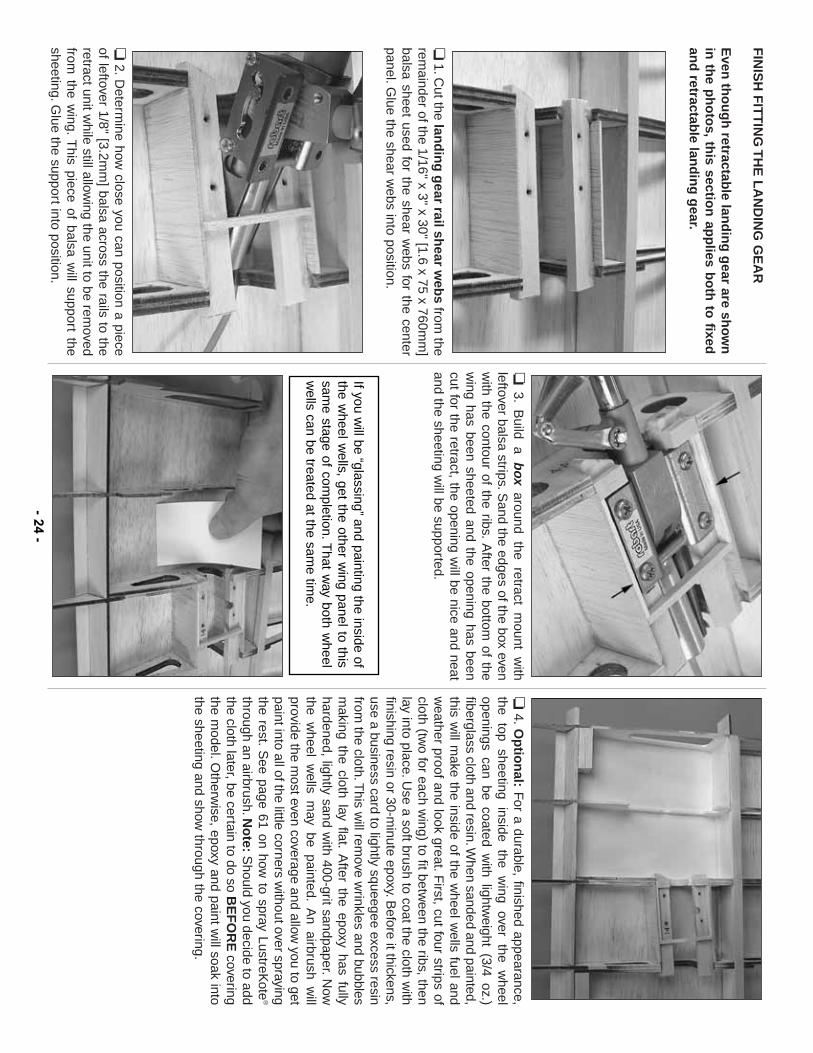
FIN
ISH
FIT
TIN
G T
HE
LA
ND
ING
GE
AR
Even
tho
ug
h retractab
le land
ing
gear are sh
ow
nin
the p
ho
tos,
this sectio
n ap
plies b
oth
to fixed
and
retractable lan
din
g g
ear.
❏1.C
ut the land
ing
gear rail sh
ear web
sfrom
therem
ainder of the 1/16" x 3" x 30" [1.6 x 75 x 760mm
]balsa sheet used for the shear w
ebs for the centerpanel.G
lue the shear webs into position.
❏2.D
etermine how
close you can position a pieceof leftover 1/8" [3.2m
m] balsa across the rails to the
retract unit while still allow
ing the unit to be removed
from the w
ing.T
his piece of balsa will support the
sheeting.Glue the support into position.
❏3.
Build a b
oxaround the retract m
ount with
leftover balsa strips.Sand the edges of the box even
with the contour of the ribs.
After the bottom
of thew
ing has been sheeted and the opening has beencut for the retract, the opening w
ill be nice and neatand the sheeting w
ill be supported.
❏4.O
ptio
nal:
For a durable, finished appearance,
the top
sheeting inside
the w
ing over
the w
heelopenings can be coated w
ith lightweight (3/4 oz.)
fiberglass cloth and resin.When sanded and painted,
this will m
ake the inside of the wheel w
ells fuel andw
eather proof and look great.First, cut four strips of
cloth (two for each w
ing) to fit between the ribs, then
lay into place.Use a soft brush to coat the cloth w
ithfinishing resin or 30-m
inute epoxy.Before it thickens,
use a business card to lightly squeegee excess resinfrom
the cloth.This w
ill remove w
rinkles and bubblesm
aking the cloth lay flat.A
fter the epoxy has fullyhardened, lightly sand w
ith 400-grit sandpaper.Now
the wheel w
ells may be painted.
An airbrush w
illprovide the m
ost even coverage and allow you to get
paint into all of the little corners without over spraying
the rest.S
ee page 61 on how to spray LustreK
ote®
through an airbrush.No
te:S
hould you decide to addthe cloth later, be certain to do so B
EF
OR
Ecovering
the model.O
therwise, epoxy and paint w
ill soak intothe sheeting and show
through the covering.
If you will be “glassing”
and painting the inside ofthe w
heel wells, get the other w
ing panel to thissam
e stage of completion.T
hat way both w
heelw
ells can be treated at the same tim
e.
- 24-
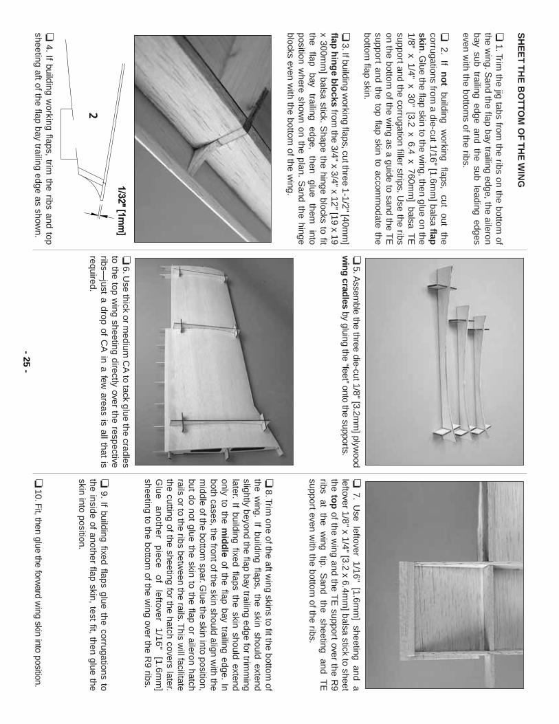
SH
EE
T T
HE
BO
TTO
M O
F T
HE
WIN
G
❏1.Trim
the jig tabs from the ribs on the bottom
ofthe w
ing.Sand the flap bay trailing edge, the aileron
bay sub trailing edge and the sub leading edgeseven w
ith the bottoms of the ribs.
❏2.
If n
ot
building w
orking flaps,
cut out
thecorrugations from
a die-cut 1/16" [1.6mm
] balsa flapskin
.Glue the flap skin to the w
ing, then glue on the1/8" x 1/4" x 30" [3.2 x 6.4 x 760m
m] balsa T
Esupport and the corrugation filler strips.U
se the ribson the bottom
of the wing as a guide to sand the T
Esupport and the top flap skin to accom
modate the
bottom flap skin.
❏3.If building w
orking flaps, cut three 1-1/2" [40mm
]flap
hin
ge b
locks
from the 3/4" x 3/4" x 12" [19 x 19
x 300mm
] balsa stick.S
hape the hinge blocks to fitthe
flap bay
trailing edge,
then glue
them
intoposition w
here shown on the plan.
Sand the hinge
blocks even with the bottom
of the wing.
❏4.
If building working flaps, trim
the ribs and topsheeting aft of the flap bay trailing edge as show
n.
❏5.A
ssemble the three die-cut 1/8" [3.2m
m] plyw
oodw
ing cradlesby gluing the “feet”onto the supports.
❏6.U
se thick or medium
CA
to tack glue the cradlesto the top w
ing sheeting directly over the respectiveribs—
just a drop of CA
in a few areas is all that is
required.
❏7.
Use leftover 1/16" [1.6m
m] sheeting and a
leftover 1/8" x 1/4" [3.2 x 6.4mm
] balsa stick to sheetthe to
pof the w
ing and the TE
support over the R9
ribs at
the w
ing tip.
Sand
the sheeting
and T
Esupport even w
ith the bottom of the ribs.
❏8.Trim
one of the aft wing skins to fit the bottom
ofthe w
ing.If building flaps, the skin should extend
slightly beyond the flap bay trailing edge for trimm
inglater.
If building fixed flaps the skin should extendonly to the m
idd
leof the flap bay trailing edge.
Inboth cases, the front of the skin should align w
ith them
iddle of the bottom spar.G
lue the skin into position,but do not glue the skin to the flap or aileron hatchrails or to the ribs betw
een the rails.This w
ill facilitatethe cutting of the sheeting for the hatch covers later.G
lue
a
no
the
r p
iece
o
f le
ftover
1/1
6"
[1.6
mm
]sheeting to the bottom
of the wing over the R
9 ribs.
❏9.
If building fixed flaps glue the corrugations tothe inside of another flap skin, test fit, then glue theskin into position.
❏10.F
it, then glue the forward w
ing skin into position.- 25
-
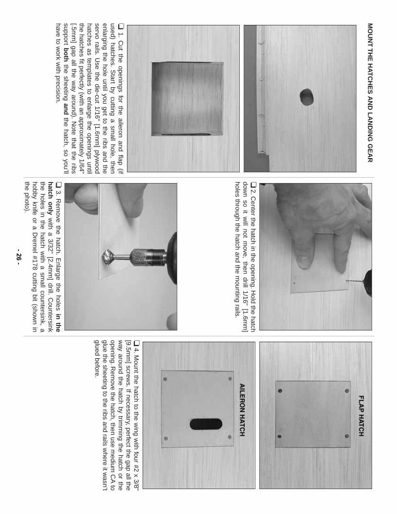
MO
UN
T T
HE
HA
TC
HE
S A
ND
LA
ND
ING
GE
AR
❏1.
Cut the openings for the aileron and flap (if
used) hatches.S
tart by cutting a small hole, then
enlarging the hole until you get to the ribs and theservo rails.
Use the die-cut 1/16" [1.6m
m] plyw
oodhatches as tem
plates to enlarge the openings untilthe hatches fit perfectly (w
ith an approximately 1/64"
[.5mm
] gap all the way around).
Note that the ribs
support bo
ththe sheeting an
dthe hatch, so you’ll
have to work w
ith precision.
❏2.C
enter the hatch in the opening.Hold the hatch
down so it w
ill not move, then drill 1/16" [1.6m
m]
holes through the hatch and the mounting rails.
❏3.
Rem
ove the hatch.E
nlarge the holes in th
eh
atch o
nly
with a 3/32" [2.4m
m] drill.
Countersink
the holes in the hatch with a sm
all countersink, ahobby knife or a D
remel #178 cutting bit (show
n inthe photo).
❏4.M
ount the hatch to the wing w
ith four #2 x 3/8"[9.5m
m] screw
s.If necessary, perfect the gap all thew
ay around the hatch by trimm
ing the hatch or theopening.R
emove the hatch, then use m
edium C
A to
glue the sheeting to the ribs and rails where it w
asn’tglued before.
- 26-
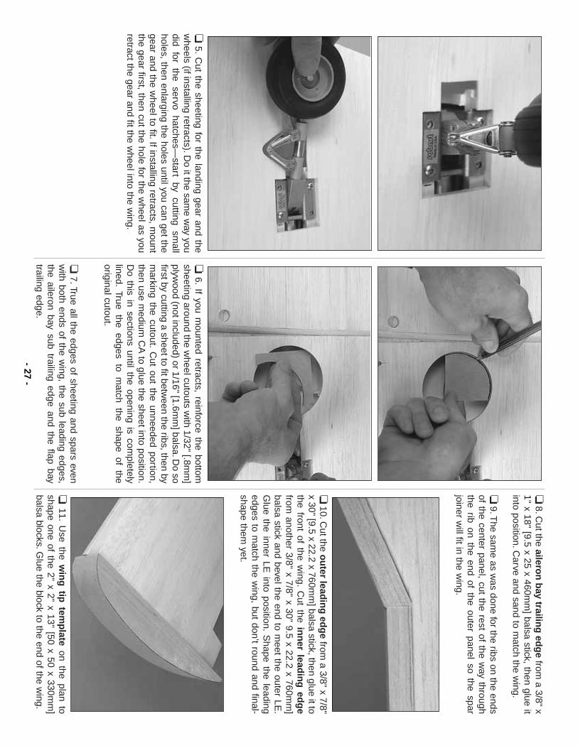
❏5.
Cut the sheeting for the landing gear and the
wheels (if installing retracts).D
o it the same w
ay youdid
for the
servo hatches—
start by
cutting sm
allholes, then enlarging the holes until you can get thegear and the w
heel to fit.If installing retracts, mount
the gear first, then cut the hole for the wheel as you
retract the gear and fit the wheel into the w
ing.
❏6.
If you mounted retracts, reinforce the bottom
sheeting around the wheel cutouts w
ith 1/32" [.8mm
]plyw
ood (not included) or 1/16" [1.6mm
] balsa.Do so
first by cutting a sheet to fit between the ribs, then by
marking the cutout.
Cut out the unneeded portion,
then use medium
CA
to glue the sheet into position.D
o this in sections until the opening is completely
lined.True the edges to m
atch the shape of theoriginal cutout.
❏7.True all the edges of sheeting and spars even
with both ends of the w
ing, the sub leading edges,the aileron bay sub trailing edge and the flap baytrailing edge.
❏8.C
ut the aileron
bay trailin
g ed
ge
from a 3/8" x
1" x 18" [9.5 x 25 x 460mm
] balsa stick, then glue itinto position.C
arve and sand to match the w
ing.
❏9.T
he same as w
as done for the ribs on the endsof the center panel, cut the rest of the w
ay throughthe rib on the end of the outer panel so the sparjoiner w
ill fit in the wing.
❏10.C
ut the ou
ter leadin
g ed
ge from
a 3/8" x 7/8"x 30" [9.5 x 22.2 x 760m
m] balsa stick, then glue it to
the front of the wing.
Cut the in
ner lead
ing
edg
efrom
another 3/8" x 7/8" x 30" 9.5 x 22.2 x 760mm
]balsa stick and bevel the end to m
eet the outer LE.
Glue the inner LE
into position.S
hape the leadingedges to m
atch the wing, but don’t round and final-
shape them yet.
❏11.
Use the w
ing
tip tem
plate
on the plan toshape one of the 2" x 2" x 13" [50 x 50 x 330m
m]
balsa blocks.Glue the block to the end of the w
ing.- 27
-
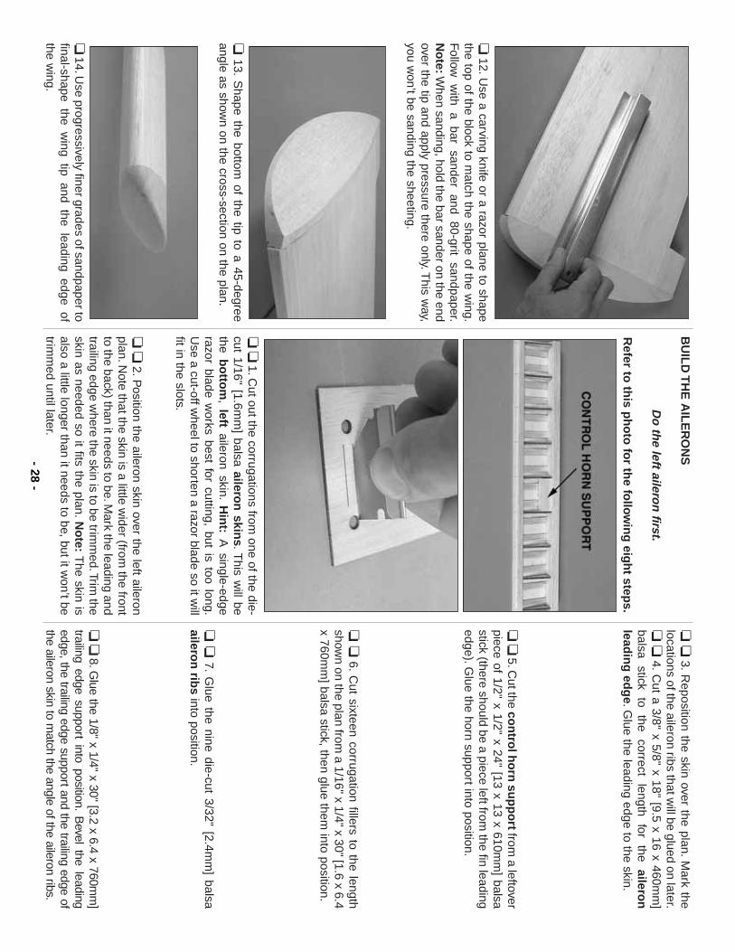
❏12.U
se a carving knife or a razor plane to shapethe top of the block to m
atch the shape of the wing.
Follow
w
ith a
bar sander
and 80-grit
sandpaper.N
ote:W
hen sanding, hold the bar sander on the endover the tip and apply pressure there only.T
his way,
you won’t be sanding the sheeting.
❏13.
Shape the bottom
of the tip to a 45-degreeangle as show
n on the cross-section on the plan.
❏14.U
se progressively finer grades of sandpaper tofinal-shape the w
ing tip and the leading edge of the w
ing.
BU
ILD
TH
E A
ILE
RO
NS
Do
the left ailero
n first.
Refer to
this p
ho
to fo
r the fo
llow
ing
eigh
t steps.
❏❏
1.Cut out the corrugations from
one of the die-cut 1/16" [1.6m
m] balsa ailero
n skin
s.This w
ill bethe b
otto
m, left
aileron skin.H
int:
A single-edge
razor blade works best for cutting, but is too long.
Use a cut-off w
heel to shorten a razor blade so it will
fit in the slots.
❏❏
2.Position the aileron skin over the left aileron
plan.Note that the skin is a little w
ider (from the front
to the back) than it needs to be.Mark the leading and
trailing edge where the skin is to be trim
med.Trim
theskin as needed so it fits the plan.N
ote:
The skin is
also a little longer than it needs to be, but it won’t be
trimm
ed until later.
❏❏
3.R
eposition the skin over the plan.M
ark thelocations of the aileron ribs that w
ill be glued on later.❏
❏4.
Cut a 3/8" x 5/8" x 18" [9.5 x 16 x 460m
m]
balsa stick
to the
correct length
for the
aileron
leadin
g ed
ge.G
lue the leading edge to the skin.
❏❏5.C
ut the con
trol h
orn
sup
po
rtfrom
a leftoverpiece of 1/2" x 1/2" x 24" [13 x 13 x 610m
m] balsa
stick (there should be a piece left from the fin leading
edge).Glue the horn support into position.
❏❏
6.C
ut sixteen corrugation fillers to the lengthshow
n on the plan from a 1/16" x 1/4" x 30" [1.6 x 6.4
x 760mm
] balsa stick, then glue them into position.
❏❏
7.G
lue the nine die-cut 3/32" [2.4mm
] balsaailero
n rib
sinto position.
❏❏8.G
lue the 1/8" x 1/4" x 30" [3.2 x 6.4 x 760mm
]trailing edge support into position.
Bevel the leading
edge, the trailing edge support and the trailing edge ofthe aileron skin to m
atch the angle of the aileron ribs.- 28
-
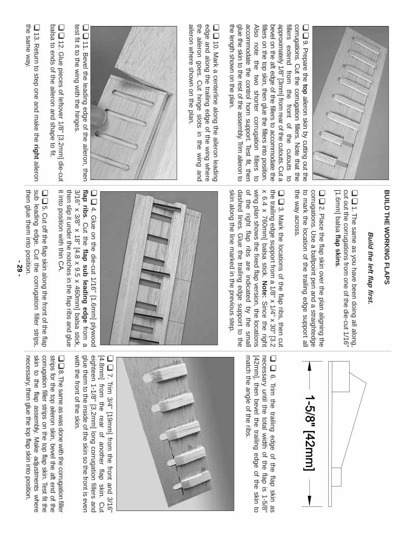
❏❏
9.Prepare the top
aileron skin by cutting out thecorrugations.
Cut the corrugation fillers.
Note that the
fillers extend
from
the front
of the
cutouts to
approximately 1/8" [3m
m] from
rear of the cutouts.Cut a
bevel on the aft edge of the fillers to accomm
odate thefillers on the top skin, then glue the fillers into position.A
lso note
the tw
o shorter
corrugation fillers
toaccom
modate the control horn support.
Test fit, thenglue the skin to the rest of the assem
bly.Trim aileron to
the length shown on the plan.
❏❏
10.Mark a centerline along the aileron leading
edge and along the trailing edge of the wing w
herethe aileron goes.
Cut hinge slots in the w
ing andaileron w
here shown on the plan.
❏❏
11.Bevel the leading edge of the aileron, then
test fit it to the wing w
ith the hinges.
❏❏
12.Glue pieces of leftover 1/8" [3.2m
m] die-cut
balsa to ends of the aileron and shape to fit.
❏13.R
eturn to step one and make the rig
ht
aileronthe sam
e way.
BU
ILD
TH
E W
OR
KIN
G F
LA
PS
Bu
ild th
e left flap first.
❏❏
1.The sam
e as you have been doing all along,cut out the corrugations from
one of the die-cut 1/16"[1.6m
m] balsa flap
skins.
❏❏
2.Place the flap skin over the plan aligning the
corrugations.Use a ballpoint pen and a straightedge
to mark the location of the trailing edge support all
the way across.
❏❏
3.M
ark the locations of the flap ribs, then cutthe trailing edge support from
a 1/8" x 1/4" x 30" [3.2x 6.4 x 760m
m] balsa stick.
No
te:S
ince the rightw
ing plan shows the fixed flap version, the locations
of the
right flap
ribs are
indicated by
the sm
alldashed lines.
Glue the trailing edge support to the
skin along the line marked in the previous step.
❏❏
4.G
lue on the die-cut 1/16" [1.6mm
] plywood
flap rib
s.C
ut the flap su
b lead
ing
edg
efrom
a3/16" x 3/8" x 18" [4.8 x 9.5 x 460m
m] balsa stick,
then slip it under the notches in the flap ribs and glueit into position w
ith thin CA
.
❏❏5.C
ut off the flap skin along the front of the flapsub leading edge.
Cut the corrugation filler strips,
then glue them into position.
❏❏
6.Trim
the trailing edge of the flap skin asnecessary until the total w
idth of the flap is 1-5/8"[42m
m], then bevel the trailing edge of the skin to
match the angle of the ribs.
❏❏
7.Trim
3/4" [19mm
] from the front and 3/16"
[4.8mm
] from
the
rear of
another flap
skin.C
uteighteen 1-1/8" [3.2m
m] long corrugation fillers and
glue them to the inside of the skin so the front is even
with the front of the skin.
❏❏8.T
he same as w
as done with the corrugation filler
strips for the top aileron skin, bevel the aft end of thecorrugation filler strips on the top flap skin.Test fit theskin to the flap assem
bly.M
ake adjustments w
herenecessary, then glue the top flap skin into position.
- 29-
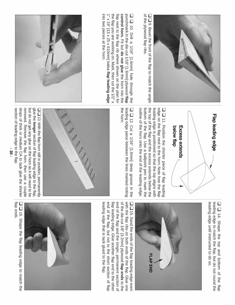
❏❏
9.Bevel the front of the flap to m
atch the angleof the plyw
ood flap ribs.
❏❏
10.D
rill a 1/16" [1.6mm
] hole through thepunchm
ark in the die-cut 1/16" [1.6mm
] plywood flap
con
trol h
orn
.F
it but do
no
t glu
ethe horn into the
flap next to the flap rib where show
n on the plan forthe flap you are w
orking on.Mark, then cut the 1/2" x
1" x 24" [13 x 25 x 610mm
] balsa flap lead
ing
edg
einto tw
o pieces at the horn.
❏❏
11.P
osition the shorter piece of flap leadingedge on the flap next to the horn.N
ote how the flap
leading edge is positioned so that the top aligns with
the top of the flap and the excess extends below the
bottom of the flap.
Use a ballpoint pen to m
ark theoutline of the horn onto the end of the leading edge.
❏❏
12.C
ut a 1/16" [1.6mm
] deep groove in theleading edge piece betw
een the lines marked noting
the horn.
❏❏13.W
ith the flap horn still in position, permanently
glue the longer
section of flap leading edge to the flap,but do not get any glue on the horn as it w
ill need to berem
oved.R
emove the flap horn, then use a couple
drops of thick or medium
CA
to tack glue the shortersection of leading edge to the flap.
❏❏
14.S
hape the
top and
bottom
of the
flapleading edge to m
atch the flap, but do not round theleading edge until instructed to do so.
❏❏15.S
and the ends of the flap leading edge evenw
ith the flap ribs on both ends of the flap.Glue one
of the die-cut 1/8" [3.2mm
] plywood flap
end
sto the
end of the flap and the longer, permanent section of
flap leading edge.Glue another flap end to the other
end of the flap, but not to the short section of flapleading edge that is tack glued to the flap.
❏❏
16.S
hape the flap leading edge to match the
flap ends.- 30
-
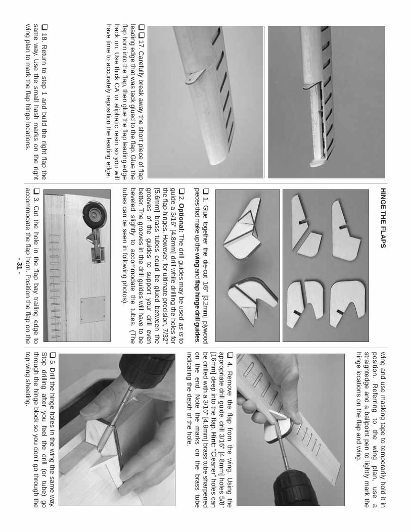
❏❏
17.Carefully break aw
ay the short piece of flapleading edge that w
as tack glued to the flap.Glue the
flap horn into the flap, then glue the flap leading edgeback on.
Use thick C
A or aliphatic resin so you w
illhave tim
e to accurately reposition the leading edge.
❏18.
Return to step 1 and build the right flap the
same w
ay.U
se the small hash m
arks on the rightw
ing plan to mark the flap hinge locations.
HIN
GE
TH
E F
LA
PS
❏1.
Glue together the die-cut 1/8" [3.2m
m] plyw
oodpieces that m
ake up the wing
and flap hinge drill guides.
❏2.O
ptio
nal:T
he drill guides may be used as is
toguide a 3/16" [4.8m
m] drill w
hile drilling the holes forthe flap hinges.H
owever, for ultim
ate precision, 7/32"[5.6m
m] brass tubes could be glued betw
een thegrooves
of the
guides to
support your
drill even
better.The grooves in the drill guides w
ill have to bebeveled
slightly to
accomm
odate the
tubes.(T
hetubes can be seen in follow
ing photos).
❏3.
Cut the hole in the flap bay trailing edge to
accomm
odate the flap horn.Position the flap on the
wing and use m
asking tape to temporarily hold it in
po
sition
.R
efe
rring
to
th
e
win
g
pla
n,
use
a
straightedge and a ballpoint pen to lightly mark the
hinge locations on the flap and wing.
❏4.
Rem
ove the
flap from
the
wing.
Using
theappropriate drill guide, drill 3/16" [4.8m
m] holes 5/8"
[16mm
] deep into the flap.Hin
t:“C
leaner”holes can
be drilled with a 3/16" [4.8m
m] brass tube sharpened
on the
end.N
ote the
marks
on the
brass tube
indicating the depth of the hole.
❏5.D
rill the hinge holes in the wing the sam
e way.
Stop
drilling after
you feel
the drill
(or tube)
gothrough the hinge block so you don’t go through thetop w
ing sheeting.- 31
-
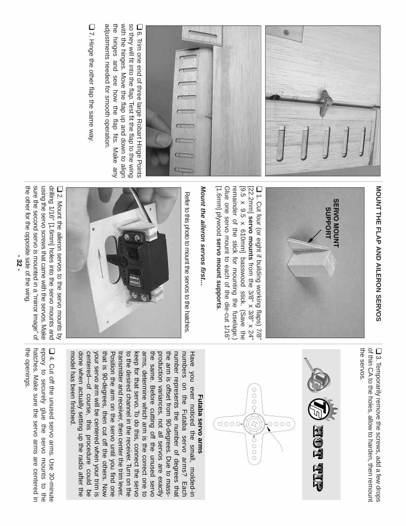
❏6.Trim
one end of three large Robart H
inge Points
so they will fit into the flap.Test fit the flap to the w
ingw
ith the hinges.Move the flap up and dow
n to alignthe
hinges and
see how
the
flap fits.
Make
anyadjustm
ents needed for smooth operation.
❏7.H
inge the other flap the same w
ay.
MO
UN
T T
HE
FL
AP
AN
D A
ILE
RO
N S
ER
VO
S
❏1.C
ut four (or eight if building working flaps) 7/8"
[22.2mm
] servo m
ou
nts
from the 3/8" x 3/8" x 24"
[9.5 x
9.5 x
610mm
] bassw
ood stick.
(Save
therem
ainder of the stick for mounting the fuselage.)
Glue one servo m
ount to each of the die-cut 1/16"[1.6m
m] plyw
ood servo m
ou
nt su
pp
orts.
Mo
un
t the ailero
n servo
s first…
Refer to this photo to m
ount the servos to the hatches.
❏2.M
ount the aileron servos to the servo mounts by
drilling 1/16" [1.6mm
] holes into the servo mounts and
using the servo screws that cam
e with the servos.M
akesure the second servo is m
ounted in a “mirror im
age”ofthe other for the opposite side of the w
ing.
❏3.Tem
porarily remove the screw
s, add a few drops
of thin CA
to the holes, allow to harden, then rem
ountthe servos.
❏4.C
ut off the unused servo arms.U
se 30-minute
epoxy to
securely glue
the servo
mounts
to the
hatches.M
ake sure the servo arms are centered in
the openings.
Fu
taba servo
arms
Have
you ever
noticed the
small,
molded-in
num
be
rs o
n
the
F
uta
ba
se
rvo a
rms?
E
ach
number represents the num
ber of degrees thatthe arm
is offset from 90-degrees.
Due to m
ass-production variances, not all servos are exactlythe sam
e.B
efore cutting off the unused servoarm
s, determine w
hich arm is the correct one to
keep for that servo.To do this, connect the servoto the desired channel in the receiver.Turn on thetransm
itter and receiver, then center the trim lever.
Position the arm
on the servo until you find onethat is 90-degrees, then cut off the others.
Now
your servo arm w
ill be centered when your trim
iscentered—
of course,
this procedure
could be
done when actually setting up the radio after the
model has been finished.
- 32-
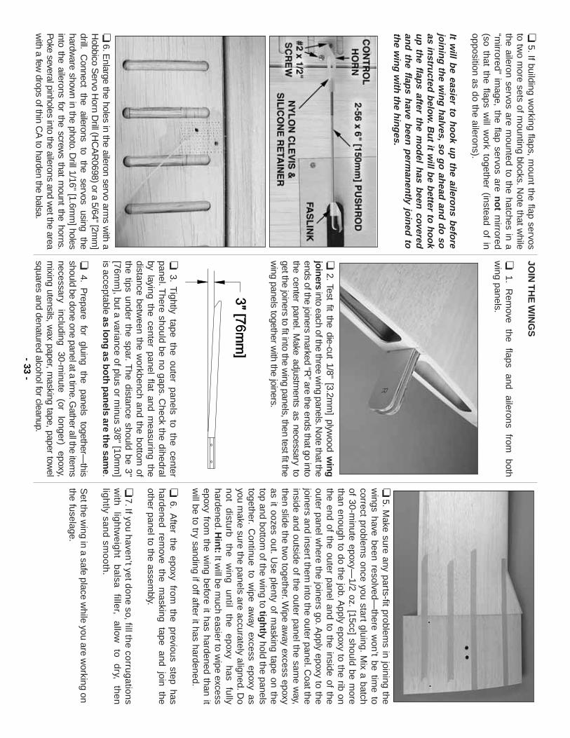
❏5.If building w
orking flaps, mount the flap servos
to two m
ore sets of mounting blocks.N
ote that while
the aileron servos are mounted to the hatches in a
“mirrored”
image, the flap servos are n
ot
mirrored
(so that the flaps will w
ork together (instead of inopposition as do the ailerons).
It will b
e easier to h
oo
k up
the ailero
ns b
efore
join
ing
the w
ing
halves,so
go
ahead
and
do
soas in
structed
below
.Bu
t it will b
e better to
ho
ok
up
the flap
s after the m
od
el has b
een covered
and
the flap
s have b
een p
erman
ently jo
ined
toth
e win
g w
ith th
e hin
ges.
❏6.E
nlarge the holes in the aileron servo arms w
ith aH
obbico Servo H
orn Drill (H
CA
R0698) or a 5/64" [2m
m]
drill.C
onnect the
ailerons to
the servos
using the
hardware show
n in the photo.Drill 1/16" [1.6m
m] holes
into the ailerons for the screws that m
ount the horns.P
oke several pinholes into the ailerons and wet the area
with a few
drops of thin CA
to harden the balsa.
JOIN
TH
E W
ING
S
❏1.
Rem
ove the
flaps and
ailerons from
both
wing panels.
❏2.
Test fit the die-cut 1/8" [3.2mm
] plywood w
ingjoiners into each of the three w
ing panels.Note that the
ends of the joiners marked “R
”are the ends that go intothe center panel.
Make adjustm
ents as necessary toget the joiners to fit into the w
ing panels, then test fit thew
ing panels together with the joiners.
❏3.
Tightly tape the outer panels to the center
panel.There should be no gaps.C
heck the dihedralby laying the center panel flat and m
easuring thedistance betw
een the workbench and the bottom
ofthe tips under the spar.
The distance should be 3"
[76mm
], but a variance of plus or minus 3/8" [10m
m]
is acceptable as lon
g as b
oth
pan
els are the sam
e.
❏4.
Prepare
for gluing
the panels
together—this
should be done one panel at a time.G
ather all the items
necessary including
30-minute
(or longer)
epoxy,m
ixing utensils, wax paper, m
asking tape, paper towel
squares and denatured alcohol for cleanup.
❏5.M
ake sure any parts-fit problems in joining the
wings have been resolved—
there won’t be tim
e tocorrect problem
s once you start gluing.Mix a batch
of 30-minute epoxy—
1/2 oz.[15cc] should be m
orethan enough to do the job.A
pply epoxy to the rib onthe end of the outer panel and to the inside of theouter panel w
here the joiners go.Apply epoxy to the
joiners and insert them into the outer panel.C
oat theinside and outside of the outer panel the sam
e way,
then slide the two together.W
ipe away excess epoxy
as it oozes out.U
se plenty of masking tape on the
top and bottom of the w
ing to tigh
tlyhold the panels
together.C
ontinue to wipe aw
ay excess epoxy asyou m
ake sure the panels are accurately aligned.Do
not disturb
the w
ing until
the epoxy
has fully
hardened.Hin
t:It w
ill be much easier to w
ipe excessepoxy from
the wing before it has hardened than it
will be to try sanding if off after it has hardened.
❏6.
After the epoxy from
the previous step hashardened rem
ove the masking tape and join the
other panel to the assembly.
❏7
.If you
have
n’t ye
t do
ne
so, fill the
corru
ga
tion
sw
ith
ligh
twe
igh
t b
alsa
fille
r, a
llow
to
dry,
the
nlig
htly sa
nd
smo
oth
.
Set the w
ing in a safe place while you are w
orking onthe fuselage.
- 33-
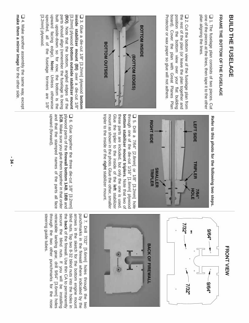
BU
ILD
TH
E F
US
EL
AG
E
FR
AM
E T
HE
BO
TTO
M O
F T
HE
FU
SE
LA
GE
❏1.T
he fuselage plan consists of two pieces.
Cut
one of the pieces at the lines, then tape it to the otherplan aligning the lines.
❏2.
Cut the bottom
view of the fuselage plan from
the rest of the plan (or leave the plan together andposition
the bottom
view
over
your flat
buildingboard).
Cover
the plan
with
Great
Planes
Plan
Protector or w
ax paper so glue will not adhere.
❏3.
Glue a die-cut 1/8" [3.2m
m] plyw
ood bo
ttom
insid
e stabilizer m
ou
nt (B
I)over a die-cut 1/8"
[3.2mm
] plywood b
otto
m o
utsid
e stabilizer m
ou
nt
(BO
).N
ote that the bottom, angled edges of the
parts should align (remem
ber the fuselage is beingbuilt
upside-down
so for
now,
the bottom
is
theu
pw
ard
fa
cing
e
dg
e).
No
te:U
nle
ss o
the
rwise
specified, all
of the
fuselage form
ers are
1/8"[3.2m
m] plyw
ood.
❏4.M
ake another assembly the sam
e way, except
make th
em a m
irror im
age
for the other side.
Refer to
this p
ho
to fo
r the fo
llow
ing
two
steps.
❏5.
Drill a 7/64" [2.8m
m] or 1/8" [3.2m
m] hole
through one of the die-cut 1/16" [1.6mm
] plywood
bo
ttom
stabilizer m
ou
nt trip
lers.N
ote that two of
these parts are included, but only the one is used.G
lue the tripler to the inside of the leftstabilizer
mount as show
n in the photo.Glue the other, sm
allertripler to the inside of the rig
ht
stabilizer mount.
❏6.
Glue together the three die-cut 1/8" [3.2m
m]
plywood parts of the firew
all bo
ttom
1AB
,1BB
and1C
B.M
ake sure you glue them together in that order
and that the stamped nam
es of the parts all faceupw
ard (forward).
❏7.
Drill
7/32" [5.6m
m]
holes through
the tw
opunchm
arks in the firewall w
here indicated by thearrow
s in the sketch for the bottom engine m
ountblind nuts.Tap tw
o 8-32 blind nuts into the holes inthe b
ackof the firew
all.Use thin C
A to perm
anentlysecure
the blind
nuts.If
you w
ill be
installingretractable landing gear, drill 9/64" [3.6m
m] holes
through the
two
other punchm
arks for
the nose
steering guide tubes.
- 34-
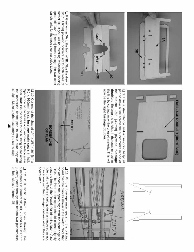
❏8.G
lue former 3A
to the front of 3B.G
lue the die-cut1/16" [1.6m
m] plyw
ood doublers 2Cto both sides of
former 2B
.If you w
ill be installing retractable landinggear, drill 9/64" [3.6m
m] holes through the tw
o otherpunchm
arks for the nose steering guide tubes.
❏9.
Use a straightedge and a fine-point ballpoint
pen to draw a line across the punchm
arks in one ofth
e
die
-cut
1/8
" [3
.2m
m]
plyw
oo
d
fuselag
ed
ou
blers.E
nlarge the notches in the doubler back tothe line by cutting aw
ay the unused material.T
his will
now be the rig
ht fu
selage d
ou
bler.
❏10.C
ut one of the shaped 1/4" x 3/8" x 36" [6.4 x9.5 x 910m
m] balsa fu
selage m
ain sp
arsin half.
Splice one of the halves onto another fuselage m
ainspar.H
int:
Pin the spars to the building board along
the borderline of the plan to make sure they are
straight.Make another assem
bly the same w
ay.
❏11.
Pin the fuselage m
ain spars to the buildingboard over the plan as show
n in the sketch.Note that
the aft ends of the spars align with the front edge of
F10B
.T
he front of the spars should extend slightlypast the front of the firew
all (for trimm
ing later).Also
note that the T-pins should go in at an angle so as notto interfere w
ith the fuselage doublers when they are
added later.
❏1
2.
Drill
3/1
6"
[4.8
mm
] h
ole
s th
rou
gh
th
epunchm
arks in formers 9B
, 8B, 7B
and 6B.D
rill 1/8"[3.2m
m] holes through the bottom
two punchm
arkson both sides of form
er 2B.
- 35-
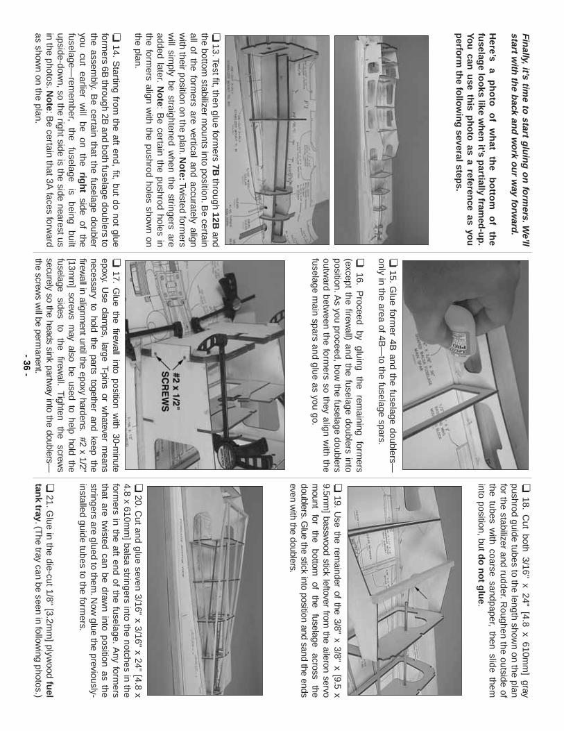
Fin
ally,it’s time to
start glu
ing
on
form
ers.We’ll
start with
the b
ack and
wo
rk ou
r way fo
rward
.
Here’s
a p
ho
to
of
wh
at th
e b
otto
m
of
the
fuselag
e loo
ks like wh
en it’s p
artially framed
-up
.Yo
u can
use th
is ph
oto
as a reference as yo
up
erform
the fo
llow
ing
several steps.
❏13.Test fit, then glue form
ers 7Bthrough 12B
andthe bottom
stabilizer mounts into position.B
e certainall of the form
ers are vertical and accurately alignw
ith their position on the plan.No
te:Twisted form
ersw
ill simply be straightened w
hen the stringers areadded later.
No
te:B
e certain the pushrod holes inthe form
ers align with the pushrod holes show
n onthe plan.
❏14.
Starting from
the aft end, fit, but do not glueform
ers 6B through 2B
and both fuselage doublers tothe assem
bly.B
e certain that the fuselage doubleryou
cut earlier
will
be on
the rig
ht
side of
thefuselage—
remem
ber, the
fuselage is
being built
upside-down, so the right side is the side nearest us
in the photos.No
te:Be certain that 3A
faces forward
as shown on the plan.
❏15.
Glue form
er 4B and the fuselage doublers—
only in the area of 4B—
to the fuselage spars.
❏16.
Proceed
by gluing
the rem
aining form
ers(except the firew
all) and the fuselage doublers intoposition.A
s you proceed, bow the fuselage doublers
outward betw
een the formers so they align w
ith thefuselage m
ain spars and glue as you go.
❏17.
Glue the firew
all into position with 30-m
inuteepoxy.
Use clam
ps, large T-pins or whatever m
eansnecessary to hold the parts together and keep thefirew
all in alignment until the epoxy hardens.
#2 x 1/2"[13m
m] screw
s may also be used to help hold the
fuselage sides
to the
firewall.
Tighten
the screw
ssecurely so the heads sink partw
ay into the doublers—the screw
s will be perm
anent.
❏18.
Cut both 3/16" x 24" [4.8 x 610m
m] gray
pushrod guide tubes to the length shown on the plan
for the stabilizer and rudder.Roughen the outside of
the tubes with coarse sandpaper, then slide them
into position, but do
no
t glu
e.
❏19.
Use the rem
ainder of the 3/8" x 3/8" x [9.5 x9.5m
m] bassw
ood stick leftover from the aileron servo
mount
for the
bottom
of the
fuselage across
thedoublers.G
lue the stick into position and sand the endseven w
ith the doublers.
❏20.C
ut and glue seven 3/16" x 3/16" x 24" [4.8 x4.8 x 610m
m] balsa stringers into the notches in the
formers in the aft end of the fuselage.
Any form
ersthat are tw
isted can be drawn into position as the
stringers are glued to them.N
ow glue the previously-
installed guide tubes to the formers.
❏21.G
lue in the die-cut 1/8" [3.2mm
] plywood fu
eltan
k tray.(The tray can be seen in follow
ing photos.)- 36
-
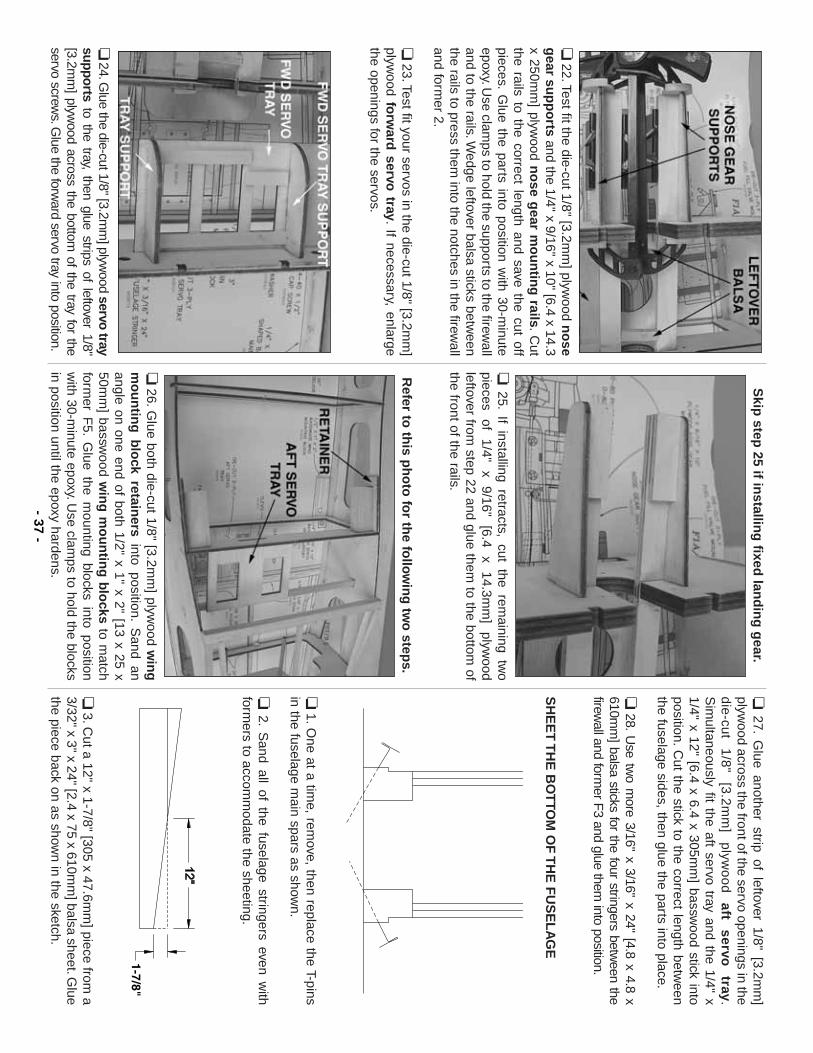
❏22.Test fit the die-cut 1/8" [3.2m
m] plyw
ood no
seg
ear sup
po
rtsand the 1/4" x 9/16" x 10" [6.4 x 14.3
x 250mm
] plywood n
ose g
ear mo
un
ting
rails.C
utthe rails to the correct length and save the cut offpieces.
Glue the parts into position w
ith 30-minute
epoxy.Use clam
ps to hold the supports to the firewall
and to the rails.Wedge leftover balsa sticks betw
eenthe rails to press them
into the notches in the firewall
and former 2.
❏23.Test fit your servos in the die-cut 1/8" [3.2m
m]
plywood fo
rward
servo tray.
If necessary, enlargethe openings for the servos.
❏24.G
lue the die-cut 1/8" [3.2mm
] plywood servo tray
supportsto the tray, then glue strips of leftover 1/8"
[3.2mm
] plywood across the bottom
of the tray for theservo screw
s.Glue the forw
ard servo tray into position.
Skip
step 25 if in
stalling
fixed lan
din
g g
ear.
❏25.
If installing retracts, cut the remaining tw
opieces
of 1/4"
x 9/16"
[6.4 x
14.3mm
] plyw
oodleftover from
step 22 and glue them to the bottom
ofthe front of the rails.
Refer to
this p
ho
to fo
r the fo
llow
ing
two
steps.
❏26.G
lue both die-cut 1/8" [3.2mm
] plywood w
ing
mo
un
ting
blo
ck retainers
into position.S
and anangle on one end of both 1/2" x 1" x 2" [13 x 25 x50m
m] bassw
ood win
g m
ou
ntin
g b
locks
to match
former F
5.G
lue the mounting blocks into position
with 30-m
inute epoxy.Use clam
ps to hold the blocksin position until the epoxy hardens.
❏27.
Glue another strip of leftover 1/8" [3.2m
m]
plywood across the front of the servo openings in the
die
-cut
1/8
" [3
.2m
m]
plyw
oo
d
aft servo
tray.
Sim
ultaneously fit the aft servo tray and the 1/4" x1/4" x 12" [6.4 x 6.4 x 305m
m] bassw
ood stick intoposition.C
ut the stick to the correct length between
the fuselage sides, then glue the parts into place.
❏28.
Use tw
o more 3/16" x 3/16" x 24" [4.8 x 4.8 x
610mm
] balsa sticks for the four stringers between the
firewall and form
er F3 and glue them
into position.
SH
EE
T T
HE
BO
TTO
M O
F T
HE
FU
SE
LA
GE
❏1.O
ne at a time, rem
ove, then replace the T-pinsin the fuselage m
ain spars as shown.
❏2.
Sand all of the fuselage stringers even w
ithform
ers to accomm
odate the sheeting.
❏3.C
ut a 12" x 1-7/8" [305 x 47.6mm
] piece from a
3/32" x 3" x 24" [2.4 x 75 x 610mm
] balsa sheet.Glue
the piece back on as shown in the sketch.
- 37-
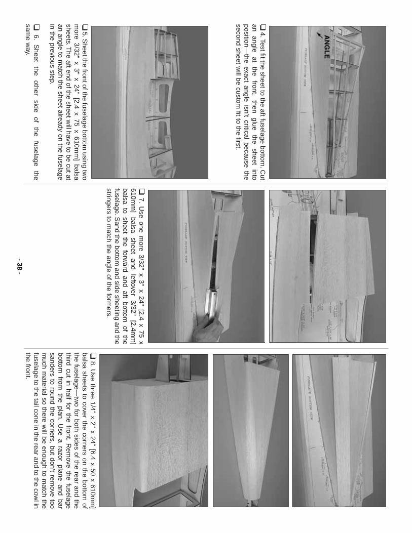
❏4.Test fit the sheet to the aft fuselage bottom
.Cut
an angle
at the
front, then
glue the
sheet into
position—the exact angle isn’t critical because the
second sheet will be custom
fit to the first.
❏5.S
heet the front of the fuselage bottom using tw
om
ore 3/32" x 3" x 24" [2.4 x 75 x 610mm
] balsasheets.T
he aft end of the sheet will have to be cut at
an angle to match the sheet already on the fuselage
in the previous step.
❏6.
Sheet
the other
side of
the fuselage
the sam
e way.
❏7.
Use one m
ore 3/32" x 3" x 24" [2.4 x 75 x610m
m]
balsa sheet
and leftover
3/32" [2.4m
m]
balsa to sheet the forward and aft bottom
of thefuselage.S
and the bottom and side sheeting and the
stringers to match the angle of the form
ers.
❏8.
Use three 1/4" x 2" x 24" [6.4 x 50 x 610m
m]
balsa sheets to cover the corners on the bottom of
the fuselage—tw
o for both sides of the rear and thethird cut in half for the front.
Rem
ove the fuselagebottom
from the plan.
Use a razor plane and bar
sanders to round the corners, but don’t remove too
much m
aterial so there will be enough to m
atch thefuselage to the tail cone in the rear and to the cow
l inthe front.
- 38-
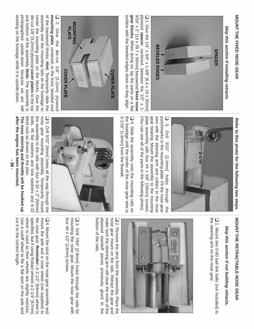
MO
UN
T T
HE
FIX
ED
NO
SE
GE
AR
Skip
this sectio
n if in
stalling
retracts.
❏1.G
lue the 1/4" x 3/4" x 1-3/8" [6.4 x 19 x 35mm
]plyw
ood spacer, centered, betw
een the 1/2" x 1-9/16" x 2" [13 x 39.7 x 50m
m] bassw
ood fixed n
ose
gear b
locks.W
hen doing so, lay the parts on a flatsurface w
ith the beveled edges down so they align.
❏2
.G
lue
th
e
die
-cut
1/8
" [3
.2m
m]
plyw
oo
dm
ou
ntin
g p
late, centered, to the front, beveled endof the bassw
ood blocks.H
int:
Temporarily slide the
assembly over the m
ounting rails on the fuselage tocenter the m
ounting plate on the blocks.G
lue thedie-cut 1/8" [3.2m
m] plyw
ood cover plates
to the topand bottom
of the assembly.N
ote:
The assem
bly isphotographed
upside-down
because w
e are
stillw
orking on the fuselage while it is upside-dow
n.
Refer to
this p
ho
to fo
r the fo
llow
ing
two
steps.
❏3
.D
rill 3
/32
" [2
.4m
m]
ho
les
thro
ug
h
the
punchmarks in the m
ounting plate.Fit the nose gear
wire w
ith the steering arm and collars to the nose
gear bearing.M
ount the assembly to the m
ountingplate assem
bly with four #4 x 5/8" [16m
m] screw
s.(You can see all of the parts in the follow
ing photo).
❏4.
Slide the assem
bly onto the mounting rails on
the fuselage until the center of the nose gear wire is
3-1/16" [1.6mm
] from the firew
all.
❏5.D
rill 5/32" [4mm
] holes all the way through the
nose gear mounting assem
bly.Tem
porarily mount
the assembly to the rails w
ith four 6-32 x 2" [50mm
]bolts, #6 flat w
ashers and lock washers and 6-32
blind nuts as shown on the plan.
Th
e no
se steering
and
thro
ttle will b
e ho
oked
up
after the en
gin
e has b
een m
ou
nted
.
MO
UN
T T
HE
RE
TR
AC
TAB
LE
NO
SE
GE
AR
Skip
this sectio
n if n
ot bu
ildin
g retracts.
❏1.M
ount two 0-80 ball link balls (not included) to
the steering arm on the nose gear.
❏2.R
emove the strut from
the assembly.P
lace thenose gear m
ount on the rails.R
etract the gear andm
ake sure the steering arm w
ill clear the ends of theplyw
ood standoff
pieces previously
glued to
thebottom
of the rails.
❏3.
Drill 7/64" [2.8m
m] holes through the rails for
mounting the nose gear.
Mount the nose gear w
ithfour #6 x 1/2" [13m
m] screw
s.
❏4.M
ount the strut on the nose gear assembly and
mount the axle and a nose w
heel (not supplied) tothe nose gear.R
emin
der:
A 2-1/2" [64m
m] w
heel isspecified, but if using R
obart wheels a 2-1/4" [57m
m]
wheel is used as their w
heels are slightly oversize.U
se a cutoff wheel to file a flat spot on the axle and
cut it to the correct length.- 39
-
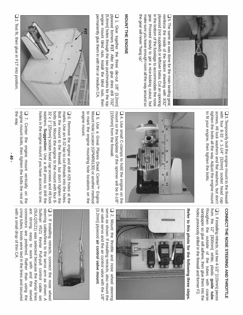
❏5.T
he same as w
as done for the main landing gear,
reinforce the inside of the bottom sheeting w
ith 3/32"plyw
ood (not supplied) or leftover balsa.Cut an opening
in the bottom of the fuselage to accom
modate the nose
gear.P
roceed slowly to get a nice-looking cutout, but
make sure you leave enough room
all the way around so
the gear will never “hang up.”
MO
UN
T T
HE
EN
GIN
E
❏1.
Glue
together the
three die-cut
1/8" [3.2m
m]
plywood form
ers F1T.
After the glue dries drill 7/32"
[5.6mm
] holes through the two punchm
arks for the topengine m
ount blind nuts.Install the blind nuts, then
permanently glue them
in with thin or m
edium C
A.
❏2.Test fit, then glue in F
1T into position.
❏3.Tem
porarily bolt the engine mount to the firew
allw
ith four 8-32 x 1-1/4" [32mm
] socket head capscrew
s, #8 lock washers and flat w
ashers, but don’ttighten the bolts all the w
ay.Adjust the engine m
ountto fit your engine, then tighten the bolts.
❏4.U
se small C
-clamps to hold the engine on the
mount so the backplate of the spinner w
ill be 6-1/8"[155m
m] from
the firewall.
❏5.
Use a G
reat Planes D
ead Center™
Engine
Mount H
ole Locator (GP
MR
8130) or another method
to mark the engine m
ounting hole locations on theengine m
ount.
❏6.
Rem
ove the engine and drill #29 holes at them
arks.Use an 8-32 tap to cut threads into the holes.
Bolt the m
ount to the firewall, but don’t tighten the
bolts yet.Mount the engine to the m
ount with four 8-
32 x 1" [25mm
] socket head cap screws and #8 lock
washers.
Su
gg
estion
:U
se a drill press to drill theholes in the engine m
ount if you have access to one.
❏7.
Center
the engine
mount
vertically on
theengine m
ount bolts, then tighten the bolts the rest ofthe w
ay.
CO
NN
EC
T THE
NO
SE
STE
ER
ING
AN
D TH
RO
TTLE
❏1.If installing retracts, cut tw
o 4-1/2" [115mm
] piecesfrom
the
12" [300m
m]
white,
plastic guide
tube.R
oughen the
outside of
the tubes
with
coarsesandpaper so glue w
ill adhere, then glue them into the
holes previously drilled in the firewall and form
er F2.
Refer to
this p
ho
to fo
r the fo
llow
ing
three step
s.
❏2.
Mount the throttle and nose w
heel steeringservo as show
n.If installing retracts, also mount the
air valve servo and the air control valve with the 1/8"
[3.2mm
] plywood air co
ntro
l valve mo
un
t.
❏3.
If installing retracts, connect the nose wheel
steering cables/lines to the servo arm as show
n.A
Sullivan
#521 K
evlar P
ull-pull control
cable set
(SU
LQ3121) w
as selected because the Kevlar lines
are strong,
easy to
work
with
and the
swivel
connectors are
preferred.R
ather than
using the
crimp tubes, knots w
ere tied in the lines and securedw
ith a small drop of thin C
A.
- 40-
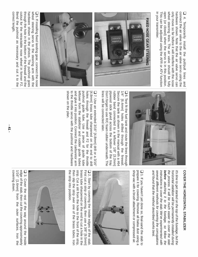
❏4.
Temporarily
install the
pull/pull lines
andconnect the air valve to the air valve servo using thehardw
are shown.
Note that the air valve servo can
only move so far before it w
ill interfere with the nose
wheel steering lines.
The air valve should be fully
open (or closed) when the servo is in this position.
This can be adjusted using the A
FR
or ATV
functionin your transm
itter.
❏5.If installing fixed landing gear, connect the nose
wheel steering servo to the steering arm
with the
hardware show
n in the photos.T
he pushrod goesthrough the hole in the bottom
of the firewall and the
cutout for the retractable nose wheel in form
er F2.
Bend the pushrod as necessary and cut it to the
correct length.
❏6.Test fit the fuel tank and route the lines through
1/4" [6.4m
m]
holes drilled
through the
firewall.
Secure the tank as show
n in the manual w
ith a #64rubber band connected to a leftover 1/8" [3.2m
m]
plywood stick glued across the bottom
of the tray.D
on’t forget to use R/C
foam rubber underneath.T
helines w
ill be connected later.
❏7.U
se an extended 3/16" [4.8mm
] drill or a 3/16"[4.8m
m] brass tube sharpened on the end to drill
holes through the firewall and F
2 for the throttlepushrod
guide tube.
Use
a piece
of guide
tubeleftover from
the stabilizer and rudder guide tubesand glue it into position.C
onnect the carburetor armto the throttle servo w
ith the pushrod and hardware
shown on the plan.
CO
VE
R T
HE
HO
RIZ
ON
TAL
STA
BIL
IZE
R
It’s time to get started on the top of the fuselage, but the
horizontal stabilizer will be perm
anently installed duringthe process.
It will be m
uch easier to cover the stabbefore
attaching it
to the
fuselage, so
follow
theinstructions to cover the stab.W
e’ve experimented w
ithseveral different m
ethods for covering the corrugationsand found that the m
ethod described works best.
❏1.If you haven’t yet done so, final-sand the stab to
prepare it for covering.Rem
ove all balsa dust using ashop-vac w
ith a brush attachment or com
pressed air.
❏2.S
tart by covering the inside edges of the stab.F
irst cut a strip of covering, then use a 3/8" [9.5mm
]brass tube sharpened on the end to cut a hole in thestrip.C
ut a slit from the hole to the front of the strip,
then slip the strip over one of the brass tubes.Iron
the strip into position.
❏3.
Cover the rest of the w
ay around the insideedge of the stab, then cut the covering approxim
ately1/16"
[1.6mm
] from
the
outer surfaces.
Iron the
covering down.
- 41-
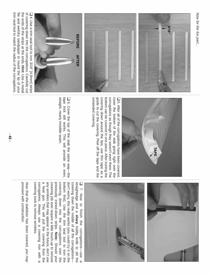
Now
for the fun part...
❏4.U
se a trim seal tool to iron 3/16" [4.8m
m] strips
of covering down into the corrugations.C
arefully cutthe ends of the strips at the ends.H
int:
Use a m
etalfile and w
et/dry sandpaper to round the tip of yourtrim
seal tool to match the radius of the corrugations.
❏5.A
fter all of the corrugations have been covered,cover the bottom
of the stab going right over thecorrugations as though they w
eren’t even there.The
bottom can be covered in one piece.A
fter ironing thecovering dow
n around the tips, use thin tape as aguide to cut the covering.
Peel off the tape and the
unneeded covering.
❏6.
Cover the top of the stab the sam
e way—
thetape
trick still
works.
This
will
provide an
even,straight, nearly invisible seam
.
❏7
.N
ow
to
finish
th
e
corru
ga
tion
s—u
se
astraightedge and a sh
arphobby knife to slit the
covering down the m
iddle of all the corrugations—don’t w
orry, this really works (you could try it on the
bottom
first).U
se the
trim
seal tool
to iron
thecoverin
g
dow
n
into
th
e
corru
ga
tion
s ove
r th
epreviously
ironed-down
strips.N
ote:
Should
yourcovering job ever require a little touch-up to rem
oveany w
rinkles that may appear in the future, don’t use
a heat
gun.T
his w
ill pull
the covering
from
thecorrugations.
Alw
ays use
a covering
iron w
ith a
covering sock to remove w
rinkles.
Now
that the stabilizer has been covered, you may
proceed with construction.
- 42-
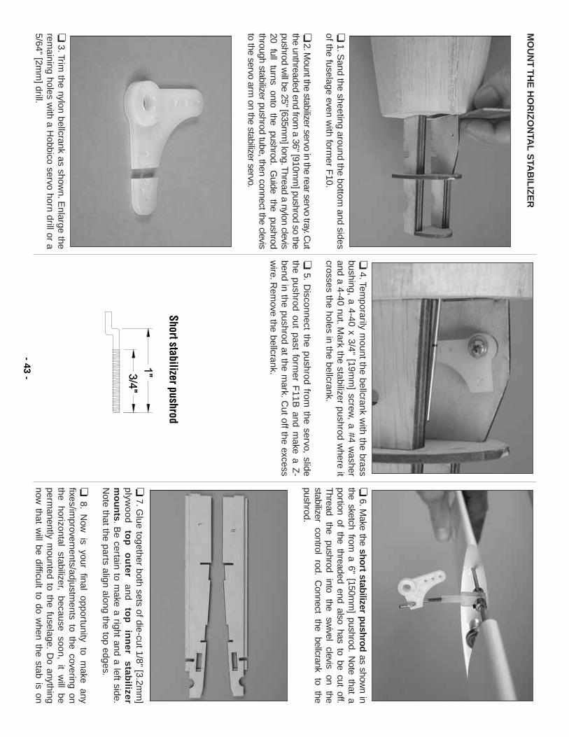
MO
UN
T T
HE
HO
RIZ
ON
TAL
STA
BIL
IZE
R
❏1.S
and the sheeting around the bottom and sides
of the fuselage even with form
er F10.
❏2.M
ount the stabilizer servo in the rear servo tray.Cut
the unthreaded end from a 36" [910m
m] pushrod so the
pushrod will be 25" [635m
m] long.T
hread a nylon clevis20
full turns
onto the
pushrod.G
uide the
pushrodthrough stabilizer pushrod tube, then connect the clevisto the servo arm
on the stabilizer servo.
❏3.Trim
the nylon bellcrank as shown.E
nlarge therem
aining holes with a H
obbico servo horn drill or a5/64" [2m
m] drill.
❏4.Tem
porarily mount the bellcrank w
ith the brassbushing, a 4-40 x 3/4" [19m
m] screw
, a #4 washer
and a 4-40 nut.Mark the stabilizer pushrod w
here itcrosses the holes in the bellcrank.
❏5.
Disconnect the pushrod from
the servo, slidethe pushrod out past form
er F11B
and make a Z
-bend in the pushrod at the m
ark.Cut off the excess
wire.R
emove the bellcrank.
❏6.M
ake the short stabilizer pushrodas show
n inthe sketch from
a 6" [150mm
] pushrod.N
ote that aportion of the threaded end also has to be cut off.T
hread the
pushrod into
the sw
ivel clevis
on the
stabilizer control
rod.C
onnect the
bellcrank to
thepushrod.
❏7.G
lue together both sets of die-cut 1/8" [3.2mm
]p
lywo
od
to
p
ou
terand
top
in
ner
stabilizer
mo
un
ts.B
e certain to make a right and a left side.
Note that the parts align along the top edges.
❏8.
Now
is
your final
opportunity to
make
anyfixes/im
provements/adjustm
ents to the covering onthe
horizontal stabilizer,
because soon,
it w
ill be
permanently m
ounted to the fuselage.D
o anythingnow
that will be difficult to do w
hen the stab is on - 43
-
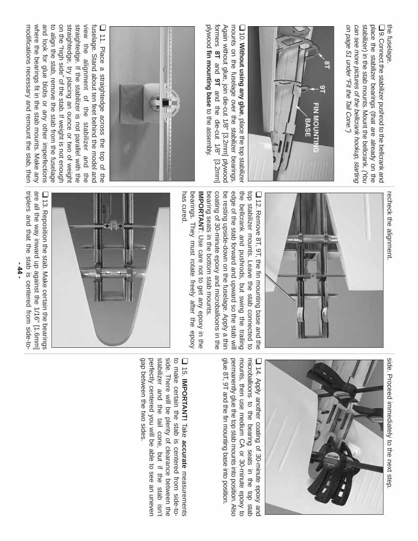
the fuselage.❏
9.Connect the stabilizer pushrod to the bellcrank and
place the stabilizer bearings (that are already on thestabilizer) in the stab m
ounts.Mount the bellcrank.(You
can see more pictures of the bellcrank hookup, starting
on page 51 under “Fit the Tail Cone.”)
❏10.W
ithout using any glue, place the top stabilizerm
ounts on the fuselage over the stabilizer bearings.A
gain without glue, join die-cut 1/8" [3.2m
m] plyw
oodform
ers 8T
and 9T
and the
die-cut 1/8"
[3.2mm
]plyw
ood fin mounting base
to the assembly.
❏11.
Place a straightedge across the top of the
fuselage.Stand about ten feet behind the m
odel andview
th
e
alig
nm
en
t o
f th
e
stab
ilizer
an
d
the
straightedge.If the stabilizer is not parallel w
ith thestraightedge, try placing an ounce or tw
o of weight
on the “high side”of the stab.If w
eight is not enoughto align the stab, rem
ove the stab from the fuselage
and look for glue blobs or any other imperfections
where the bearings fit in the stab m
ounts.Make any
modifications necessary and rem
ount the stab, then
recheck the alignment.
❏12.R
emove 8T, 9T, the fin m
ounting base and thetop stabilizer m
ounts.Leave the stab connected to
the bellcrank and pushrods, but swing the trailing
edge of the stab forward and upw
ard so the stab will
be resting upside-down on the fuselage.A
pply a thincoating of 30-m
inute epoxy and microballoons in the
bearing seats in the bottom stab m
ounts.IM
PO
RTA
NT
:U
se care not to get any epoxy in thebearings.
They m
ust rotate freely after the epoxy has cured.
❏13.R
eposition the stab.Make certain the bearings
are all the way inw
ard up against the 1/16" [1.6mm
]triplers and that the stab is centered from
side-to-
side.Proceed im
mediately to the next step.
❏14.
Apply another coating of 30-m
inute epoxy andm
icroballoons to
the bearing
seats in
the top
stabm
ounts, then use medium
CA
or 30-minute epoxy to
permanently glue the top stab m
ounts into position.Also
glue 8T, 9T and the fin m
ounting base into position.
❏15.
IMP
OR
TAN
T!
Take accurate
measurem
entsto m
ake certain the stab is centered from side-to-
side.There w
ill be plenty of clearance between the
stabilizer and
the tail
cone, but
if the
stab isn’t
perfectly centered you will be able to see an uneven
gap between the tw
o sides.
- 44-
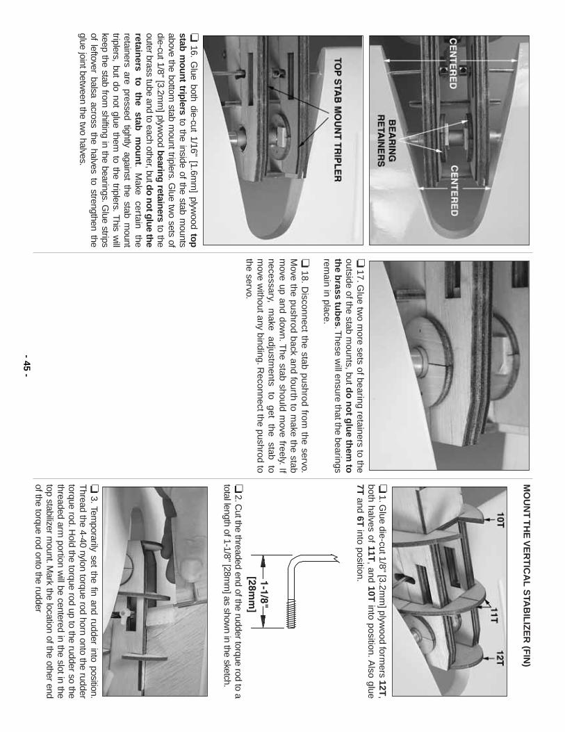
❏16.
Glue both die-cut 1/16" [1.6m
m] plyw
ood topstab m
ount triplersto the inside of the stab m
ountsabove the bottom
stab mount triplers.G
lue two sets of
die-cut 1/8" [3.2mm
] plywood bearing retainers
to theouter brass tube and to each other, butdo not glue theretain
ers to
th
e stab
m
ou
nt.
Make
certain the
retainers are pressed tightly against the stab mount
triplers, but do not glue them to the triplers.T
his will
keep the stab from shifting in the bearings.G
lue stripsof leftover balsa across the halves to strengthen theglue joint betw
een the two halves.
❏17.G
lue two m
ore sets of bearing retainers to theoutside of the stab m
ounts, but do
no
t glu
e them
toth
e brass tu
bes.T
hese will ensure that the bearings
remain in place.
❏18.
Disconnect the stab pushrod from
the servo.M
ove the pushrod back and fourth to make the stab
move up and dow
n.The stab should m
ove freely.If
necessary, m
ake adjustm
ents to
get the
stab to
move w
ithout any binding.Reconnect the pushrod to
the servo.
MO
UN
T T
HE
VE
RT
ICA
L S
TAB
ILIZ
ER
(FIN
)
❏1.G
lue die-cut 1/8" [3.2mm
] plywood form
ers 12T,
both halves of 11T, and 10T
into position.Also glue
7Tand 6T
into position.
❏2.C
ut the threaded end of the rudder torque rod to atotal length of 1-1/8" [28m
m] as show
n in the sketch.
❏3.Tem
porarily set the fin and rudder into position.T
hread the 4-40 nylon torque rod horn onto the ruddertorque rod.H
old the torque rod up to the rudder so thethreaded arm
portion will be centered in the slot in the
top stabilizer mount.M
ark the location of the other endof the torque rod onto the rudder
- 45-
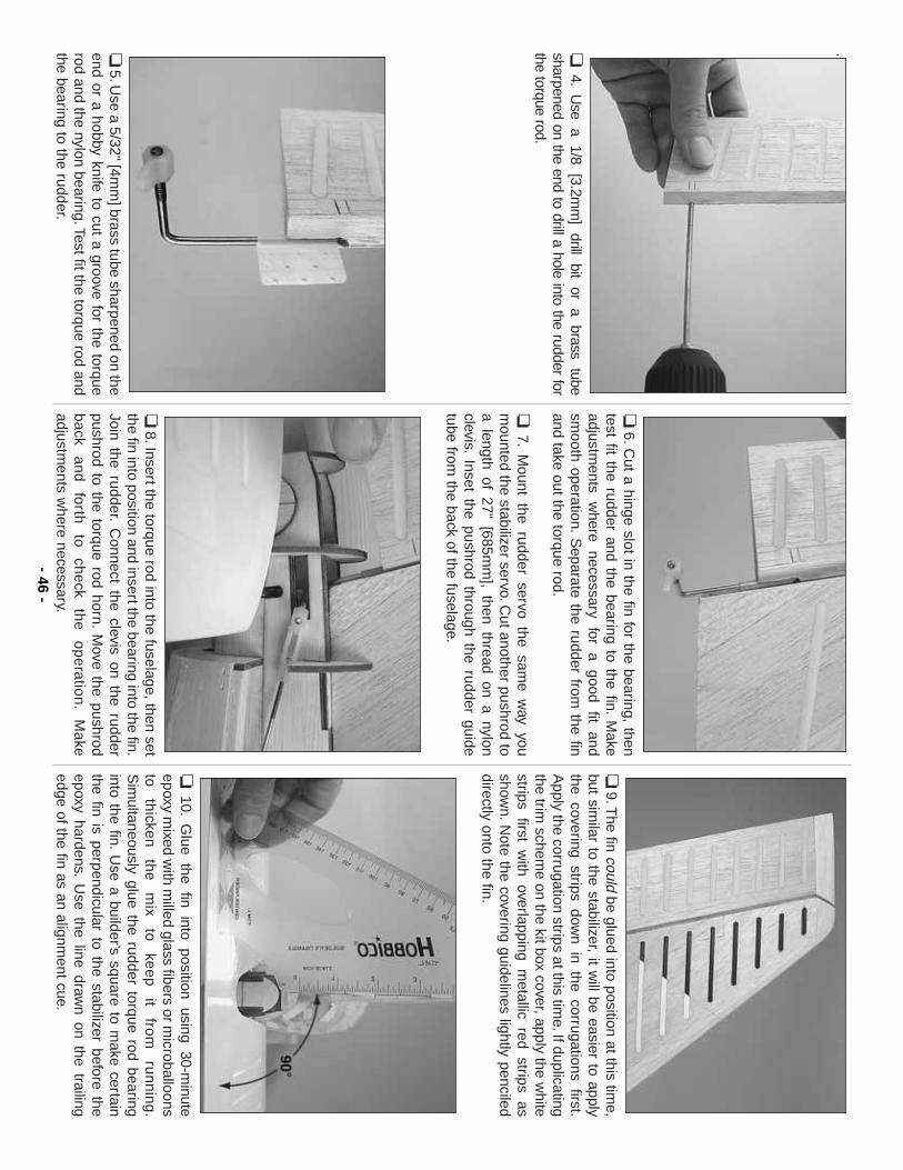
.❏4.
Use
a 1/8
[3.2mm
] drill
bit or
a brass
tubesharpened on the end to drill a hole into the rudder forthe torque rod.
❏5.U
se a 5/32" [4mm
] brass tube sharpened on theend or a hobby knife to cut a groove for the torquerod and the nylon bearing.Test fit the torque rod andthe bearing to the rudder.
❏6.C
ut a hinge slot in the fin for the bearing, thentest fit the rudder and the bearing to the fin.
Make
adjustments
where
necessary for
a good
fit and
smooth operation.
Separate the rudder from
the finand take out the torque rod.
❏7.
Mount the rudder servo the sam
e way you
mounted the stabilizer servo.C
ut another pushrod toa length of 27" [685m
m], then thread on a nylon
clevis.Inset the pushrod through the rudder guide
tube from the back of the fuselage.
❏8.Insert the torque rod into the fuselage, then set
the fin into position and insert the bearing into the fin.Join the rudder.
Connect the clevis on the rudder
pushrod to the torque rod horn.M
ove the pushrodb
ack
an
d
forth
to
che
ck th
e
op
era
tion
.M
ake
adjustments w
here necessary.
❏9.T
he fin couldbe glued into position at this tim
e,but sim
ilar to the stabilizer, it will be easier to apply
the covering strips down in the corrugations first.
Apply the corrugation strips at this tim
e.If duplicatingthe trim
scheme on the kit box cover, apply the w
hitestrips first w
ith overlapping metallic red strips as
shown.N
ote the covering guidelines lightly pencileddirectly onto the fin.
❏10.
Glue the fin into position using 30-m
inuteepoxy m
ixed with m
illed glass fibers or microballoons
to
thicke
n
the
m
ix to
ke
ep
it
from
ru
nn
ing
.S
imultaneously glue the rudder torque rod bearing
into the fin.U
se a builder’s square to make certain
the fin is perpendicular to the stabilizer before theepoxy hardens.
Use the line draw
n on the trailingedge of the fin as an alignm
ent cue.- 46
-
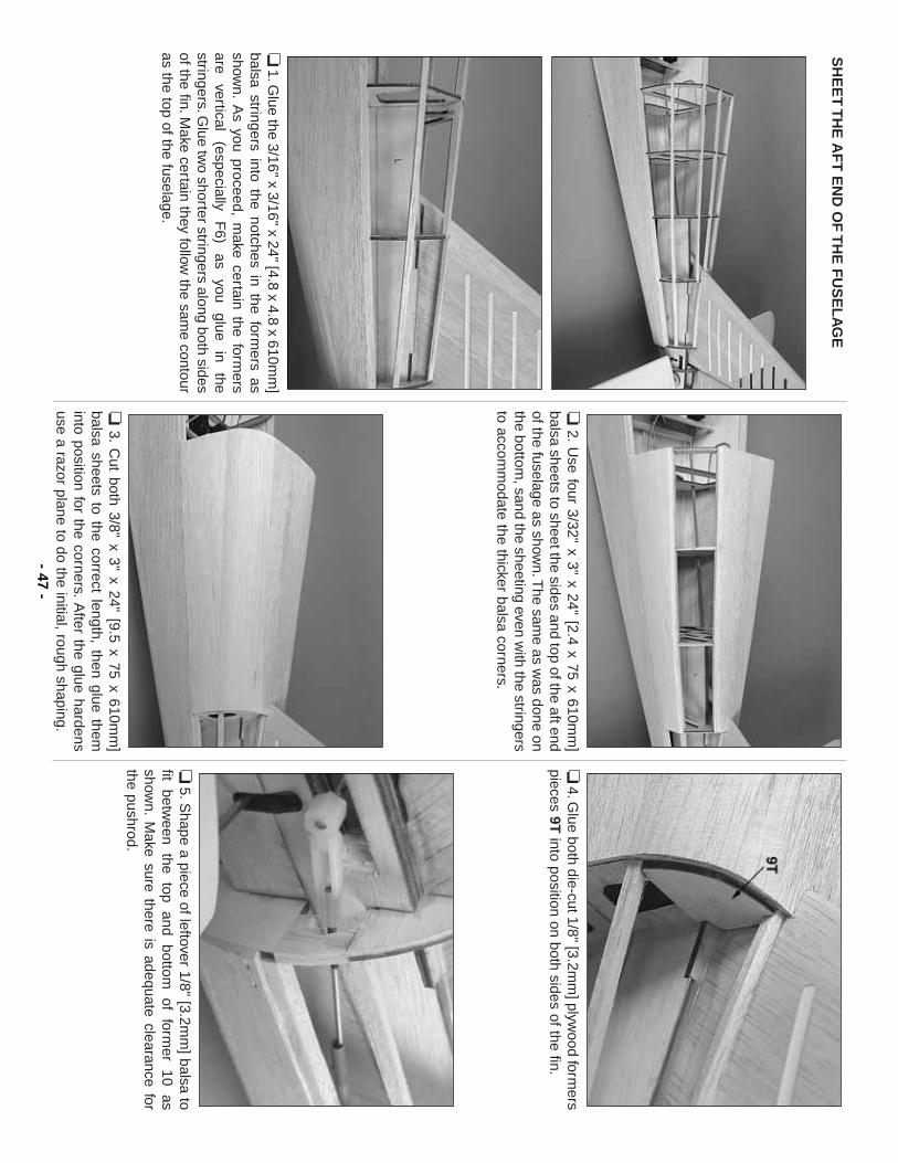
SH
EE
T T
HE
AF
T E
ND
OF
TH
E F
US
EL
AG
E
❏1.G
lue the 3/16" x 3/16" x 24" [4.8 x 4.8 x 610mm
]balsa stringers into the notches in the form
ers asshow
n.A
s you proceed, make certain the form
ersare
vertical (especially
F6)
as you
glue in
thestringers.G
lue two shorter stringers along both sides
of the fin.Make certain they follow
the same contour
as the top of the fuselage.
❏2.
Use four 3/32" x 3" x 24" [2.4 x 75 x 610m
m]
balsa sheets to sheet the sides and top of the aft endof the fuselage as show
n.The sam
e as was done on
the bottom, sand the sheeting even w
ith the stringersto accom
modate the thicker balsa corners.
❏3.
Cut both 3/8" x 3" x 24" [9.5 x 75 x 610m
m]
balsa sheets to the correct length, then glue theminto position for the corners.
After the glue hardens
use a razor plane to do the initial, rough shaping.
❏4.G
lue both die-cut 1/8" [3.2mm
] plywood form
erspieces 9T
into position on both sides of the fin.
❏5.S
hape a piece of leftover 1/8" [3.2mm
] balsa tofit
between
the top
and bottom
of
former
10 as
shown.
Make sure there is adequate clearance for
the pushrod.
- 47-
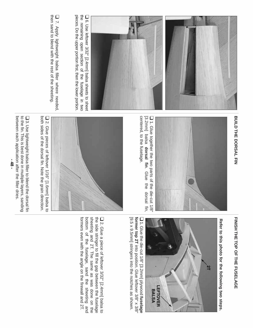
❏6.U
se leftover 3/32" [2.4mm
] balsa sheets to sheetthe
remaining
open section
of the
fuselage in
two
pieces.Do the upper portion first, then the low
er portion.
❏7.
Apply lightw
eight balsa filler where needed,
then sand to blend with the rest of the sheeting.
BU
ILD
TH
E D
OR
SA
L F
IN
❏1.G
lue together the two parts of the die-cut 1/8"
[3.2mm
] balsa
do
rsal fin
.G
lue the
dorsal fin,
centered, to the fuselage.
❏2.
Glue pieces of leftover 1/16" [1.6m
m] balsa to
both sides of the dorsal fin.Note the grain direction.
❏3.U
se lightweight balsa filler to blend the dorsal fin
to the fin.This is best done in m
ultiple layers, sandingbetw
een each application after the filler dries.
FIN
ISH
TH
E TO
P O
F T
HE
FU
SE
LA
GE
Refer to
this p
ho
to fo
r the fo
llow
ing
two
steps.
❏1.G
lue the die-cut 1/8" [3.2mm
] plywood fu
selage
form
er top
2Tinto position.G
lue leftover 3/8" x 3/8"[9.5 x 9.5m
m] stringers into the notches as show
n.
❏2.G
lue a piece of leftover 3/32" [2.4mm
] balsa tothe side stringer to fill the gap betw
een the fuselagesheeting and 2T.
The sam
e as was done on the
bottom
of the
fuselage, sand
the sheeting
andform
ers even with the angle on the firew
all and 2T.
- 48-
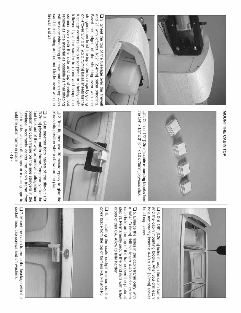
❏3.
Sheet the top of the fuselage over the firew
alland 2T
with leftover 3/32" [2.4m
m] balsa sheeting.
Bevel
the edges
of the
sheeting even
with
thestringers, then finish the top of the fuselage by gluingon leftover 3/8" x 3" [9.5 x 75m
m] balsa sheets for the
fuselage corners.Use a razor plane or a hobby knife
followed by a bar sander to round and shape the
corners even with the side and top sheeting, but
remove as little m
aterial as possible as final shapingw
ill be done when fitting the cow
l and cabin top.Also
sand the sheeting and corner blocks even with the
firewall and 2T.
MO
UN
T T
HE
CA
BIN
TOP
❏1.C
ut four 1/2" [13mm
] cabin mounting blocks
fromthe 1/4" x 1/2" x 3" [6.4 x 13 x 75m
m] plyw
ood stick.
❏2.Test fit, then use 30-m
inute epoxy to glue theblocks into position w
here shown on the plan.
❏3.
Glue together both halves of the die-cut 1/8"
[3.2mm
] plywood cab
in fram
e.Temporarily slide the
fuel tank out of the way or rem
ove it altogether, thenposition the cabin fram
e on the side stringers in thefuselage.
Accurately center the cabin fram
e fromside-to-side.
Use sm
all clamps or m
asking tape tohold the cabin fram
e in place.
❏4.D
rill 1/8" [3.2mm
] holes through the cabin frame
and the cabin mounting blocks.
After you drill each
hole temporarily insert a 4-40 x 1/2" [13m
m] socket
head cap screw.
❏5.E
nlarge the holes in the cabin frame o
nly, w
itha 9/64" [3.6m
m] drill bit.
Insert 4-40 blind nuts intoeach hole on the top of the fram
e (seethe photo at
step 7).Perm
anently secure the blind nuts with a few
drops of thin CA
.Allow
to fully harden.
❏6.
If installing the scale cockpit interior, cut thecross brace
from the top of form
ers F3, F
4 and F5.
❏7.M
ount the cabin frame to the fuselage w
ith thesocket head cap screw
s and #4 washers.
- 49-
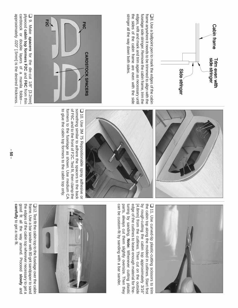
❏8.U
se a ballpoint pen to mark the edges of the cabin
frame anyw
here it needs to be trimm
ed to align with the
fuselage side stringer.Rem
ove the cabin frame, trim
theedges, refit and m
ark and trim again as necessary until
the sides of the cabin frame are even w
ith the sidestringer all the w
ay down both sides.
❏9.
Make sp
acersfor the die-cut 1/8" [3.2m
m]
plywood cab
in to
p fo
rmers F
2Cand F
6Cfrom
thincardstock
or double
layers of
a m
anila folder—
approximately .020" [.5m
m] is the desired thickness.
❏10.U
se 3M 75 R
epositionable spray adhesive orsom
ething similar to adhere the spacers to the back
of F6C
and to the front of F2C
.Test fit, then clamp the
formers to the fuselage as show
n.U
se medium
CA
to glue the cabin top formers to the cabin top only.
❏11.
Use curved-tip plastic-cutting scissors to trim
the cabin top along the molded in cutlines.S
tart firstby rough-cutting the cabin top approxim
ately 3/16"[4.8m
m] from
the cutlines.T
hen cut on the outsideedge of the cutlines to leave enough m
aterial for fine-tuning by sanding.
No
te:W
henever cutting plasticparts, alw
ays cut them slightly oversize.
Then they
can be custom-fit by sanding w
ith a bar sander.
❏12.Test fit the cabin top to the fuselage over the cabin
frame.U
se a bar sander with 80-grit sandpaper to sand
the edges of the cabin top wherever necessary to get a
good fit
all the
way
around.P
roceed slow
lyand
carefullyto get a nice fit.
- 50-
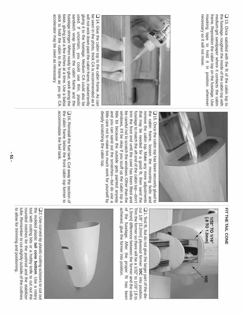
❏13.
Once satisfied w
ith the fit of the cabin top tothe fuselage, roughen the inside of the cabin top w
ithm
edium-grit sandpaper w
here it contacts the cabinfram
e.Reposition the cabin top on the fuselage.U
sem
askin
g
tap
e
to
ho
ld
it in
p
ositio
n
wh
erever
necessary so it will not m
ove.
❏14.G
lue the cabin top to the cabin frame.A
s canbe seen in the photo, thick C
A is recom
mended as it
will not w
ick down past the cabin fram
e, inadvertentlygluing it to the fuselage.
Medium
CA
could also beused.
If uncertain,
you could
use thin,
plasticsandw
ich wrap betw
een the cabin frame and the
fuselage stringer.When ready to glue, w
ork along thebase, gluing just a few
inches at a time.U
se a balsastick to hold the cabin to the fram
e as you go.C
Aaccelerator m
ay be used as necessary.
❏15.O
nce the cabin top has been securely glued tothe
cabin fram
e, loosen
the m
ounting bolts
andrem
ove the cabin top.M
ake any more adjustm
entsthat m
ay be needed for a good fit, then sand thefuselage to m
atch the aft end of the cabin top—don’t
trim the front end until the cow
l has been fitted andbe careful not to scratch the w
indows.O
ther than thew
indows, it’ll be okay if you scuff up the cabin top a
little bit because the outside gets painted anyway
and you can sand out the scratches—but do use a
little care not to make too m
uch work for yourself by
deeply scratching the cabin top.
❏16.R
einstall the fuel tank.Cut aw
ay the section ofthe cabin fram
e below the front cabin top form
er toaccom
modate the fuel tank.
FIT
TH
E TA
IL C
ON
E
❏1.Test fit, but do not glue the larger part of the die-
cut 1/8" [3.2mm
] plywood form
er 10Cinto position.
Trim the form
er so there will be a 1/32" to 1/16" [.8 to
1.5mm
] difference between the form
er and the sidesof
the fuselage.
After
the proper
fit has
beenachieved, glue the form
er into position.
❏2.U
se curved-tip plastic-cutting scissors to cut outthe m
olded plastic tail con
e bo
ttom
.U
se a rotarytool w
ith cutting bits or a hobby knife to cut out therounded notches for the pushrod and the stabilizertube.R
emem
ber to cut slightly outside of the cutlinesto allow
for trimm
ing and positioning.- 51
-
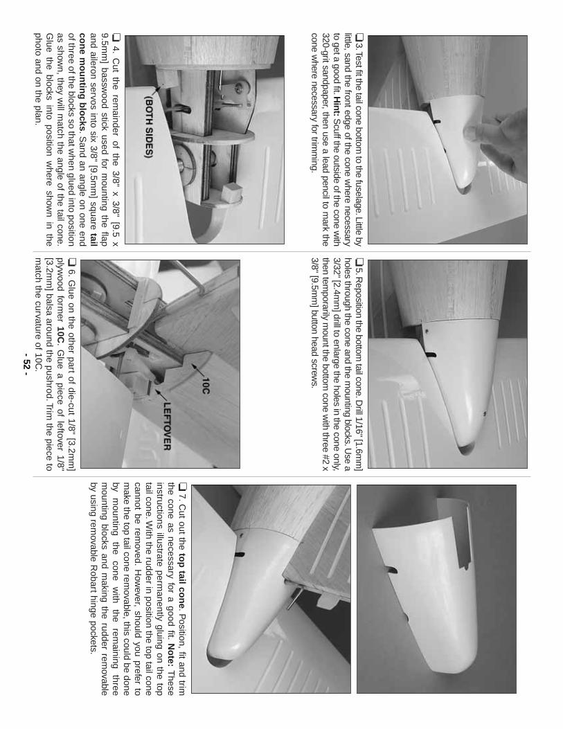
❏3.Test fit the tail cone bottom
to the fuselage.Little bylittle, sand the front edge of the cone w
here necessaryto get a good fit.H
int:Scuff the outside of the cone w
ith320-grit sandpaper, then use a lead pencil to m
ark thecone w
here necessary for trimm
ing.
❏4.
Cut the rem
ainder of the 3/8" x 3/8" [9.5 x9.5m
m] bassw
ood stick used for mounting the flap
and aileron servos into six 3/8" [9.5mm
] square tailco
ne m
ou
ntin
g b
locks.S
and an angle on one endof three of the blocks so that w
hen glued into positionas show
n, they will m
atch the angle of the tail cone.G
lue the blocks into position where show
n in thephoto and on the plan.
❏5.R
eposition the bottom tail cone.D
rill 1/16" [1.6mm
]holes through the cone and the m
ounting blocks.Use a
3/32" [2.4mm
] drill to enlarge the holes in the cone only,then tem
porarily mount the bottom
cone with three #2 x
3/8" [9.5mm
] button head screws.
❏6.
Glue on the other part of die-cut 1/8" [3.2m
m]
plywood form
er 10C.
Glue a piece of leftover 1/8"
[3.2mm
] balsa around the pushrod.Trim the piece to
match the curvature of 10C
.
❏7.C
ut out the top
tail con
e.Position, fit and trim
the cone as necessary for a good fit.N
ote:
These
instructions illustrate permanently gluing on the top
tail cone.With the rudder in position the top tail cone
cannot be removed.
How
ever, should you prefer tom
ake the top tail cone removable, this could be done
by m
ounting the
cone w
ith the
remaining
threem
ounting blocks and making the rudder rem
ovableby using rem
ovable Robart hinge pockets.
- 52-
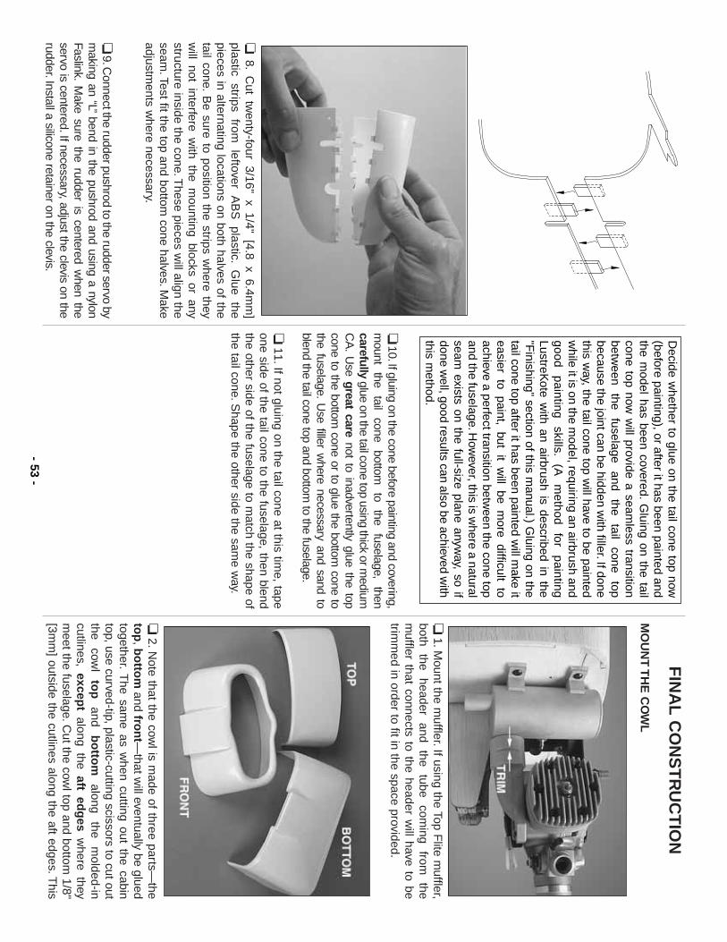
❏8.
Cut tw
enty-four 3/16" x 1/4" [4.8 x 6.4mm
]plastic
strips from
leftover
AB
S
plastic.G
lue the
pieces in alternating locations on both halves of thetail cone.
Be sure to position the strips w
here theyw
ill not interfere with the m
ounting blocks or anystructure inside the cone.T
hese pieces will align the
seam.Test fit the top and bottom
cone halves.Make
adjustments w
here necessary.
❏9.C
onnect the rudder pushrod to the rudder servo bym
aking an “L”bend in the pushrod and using a nylon
Faslink.M
ake sure the rudder is centered when the
servo is centered.If necessary, adjust the clevis on therudder.Install a silicone retainer on the clevis.
❏10.If gluing on the cone before painting and covering,
mount
the tail
cone bottom
to
the fuselage,
thencarefully
glue on the tail cone top using thick or medium
CA
.U
se great carenot to inadvertently glue the top
cone to the bottom cone or to glue the bottom
cone tothe fuselage.
Use filler w
here necessary and sand toblend the tail cone top and bottom
to the fuselage.
❏11.If not gluing on the tail cone at this tim
e, tapeone side of the tail cone to the fuselage, then blendthe other side of the fuselage to m
atch the shape ofthe tail cone.S
hape the other side the same w
ay.
FIN
AL
CO
NS
TR
UC
TIO
N
MO
UN
T T
HE
CO
WL
❏1.M
ount the muffler.If using the Top F
lite muffler,
both the
header and
the tube
coming
from
them
uffler that connects to the header will have to be
trimm
ed in order to fit in the space provided.
❏2.N
ote that the cowl is m
ade of three parts—the
top
, bo
ttom
and fron
t—that w
ill eventually be gluedtogether.
The sam
e as when cutting out the cabin
top, use curved-tip, plastic-cutting scissors to cut outthe
cowl
top
and b
otto
malong
the m
olded-incutlines, excep
talong the aft ed
ges
where they
meet the fuselage.C
ut the cowl top and bottom
1/8"[3m
m] outside the cutlines along the aft edges.T
his
Decide w
hether to glue on the tail cone top now(before painting), or after it has been painted andthe m
odel has been covered.G
luing on the tailcone top now
will provide a seam
less transitionbetw
een the
fuselage and
the tail
cone top
because the joint can be hidden with filler.If done
this way, the tail cone top w
ill have to be paintedw
hile it is on the model, requiring an airbrush and
good painting
skills.(A
m
ethod for
paintingLustreK
ote with an airbrush is described in the
"Finishing" section of this m
anual.) Gluing on the
tail cone top after it has been painted will m
ake iteasier to paint, but it w
ill be more difficult to
achieve a perfect transition between the cone top
and the fuselage.How
ever, this is where a natural
seam exists on the full-size plane anyw
ay, so ifdone w
ell, good results can also be achieved with
this method.
- 53-
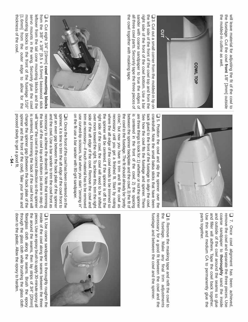
will leave m
aterial for adjusting the fit of the cowl to
the fuselage.C
ut the cowl fro
nt
1/8" [3mm
] outsidethe m
olded-in cutline as well.
❏3.C
ut out a small corner from
the molded-in lip on
the left side of the front of the cowl top and from
theright side of the front of the cow
l bottom.U
se a barsander w
ith coarse sandpaper to true the edges ofall three cow
l parts.Securely tape the three pieces of
the cowl together w
ith masking tape.
❏4.C
ut eight 3/4" [19mm
] cow
l mo
un
ting
blo
cksfrom
the 3/8" x 3/8" [9.5 x 9.5mm
] basswood stick
leftover from the tail cone m
ounting blocks and theservo m
ounts in the wing.
Securely glue the cow
lm
ounting blocks to the front of the fuselage 1/16"[1.6m
m]
from
the outer
edge to
allow
for the
thickness of the cowl.
❏5.
Position the cow
l and slip the spinner over thecrankshaft.N
ote the small balsa sticks that have been
tack glued to the front of the fuselage to align the cowl.
See how
the cowl fits the fuselage and spinner.T
hereare three things to look for:1) w
hether or not the spinneris centered in the front of the cow
l;2) the spacing
between the spinner backplate and the cow
l;3) the fit ofthe cow
l to the fuselage.The fit should already be “pretty
close,”but now
you have to trim and fit the cow
l asnecessary until you get a finished fit.
Start by noting
where the aft edge of the cow
l needs to be trimm
ed sothe spinner w
ill be centered.If the spinner is off to theright side of the cow
l, the cowl w
ill need to be shiftedover m
ore toward the right.To achieve this, trim
the rightside of the aft edge of the cow
l.Rem
ove the cowl and
trim as necessary—
if much m
aterial has to be removed
use curved-tip scissors, but when you start “zeroing in”
on the fit use a bar sander with 80-grit sandpaper.
❏6.O
nce the front of the cowl has been centered on the
spinner, it is time to trim
the aft edge of the cowl front to
get an even gap between the back plate of the spinner
and the cowl.U
se a bar sander to trim the cow
l front asnecessary to achieve the desired fit.N
ote that trimm
ingthe back of the cow
l top and bottom (as done in step 4)
will “steer”the cow
l in the correct direction so the spinneris centered, but trim
ming the back of the cow
l front will
change the spinner gap (between the back plate of the
spinner and the front of the cowl).Take your tim
e andproceed slow
ly to get a good fit.
❏7.
Once
cowl
alignment
has been
achieved,rem
ove the cowl and separate the three pieces.U
secoarse sandpaper to th
oro
ug
hly
sand the insideand outside of the cow
l around the seams so glue
and filler will adhere.
Tape the cowl back together.
Use thin and m
edium C
A to perm
anently glue theparts together.
❏8.R
emove the m
asking tape and refit the cowl to
the fuselage.
Make
any final
trim
adjustments
necessary for a good fit between the cow
l and thefuselage and betw
een the cowl and the spinner.
❏9.U
se coarse sandpaper to thoroughly roughen theinside of the cow
l along the seams betw
een the threepieces.U
se an epoxy brush to apply 30-minute epoxy all
the around the seams, then lay strips of 3/4" [20m
m]
fiberglass cloth
along the
seams.
Brush
the epoxy
through the glass cloth while brushing the glass cloth
down to the plastic.A
llow the epoxy to harden.
- 54-
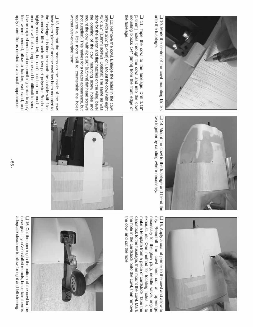
❏10.
Mark the center of the cow
l mounting blocks
onto the fuselage.
❏11.
Tape the
cowl
to the
fuselage.D
rill 1/16"
[1.6mm
] holes through the cowl and into the cow
lm
ounting blocks 1/4" [6mm
] from the front edge of
the fuselage.
❏12.R
emove the cow
l.Enlarge the holes in the cow
lonly w
ith a 3/32" [2.4mm
] drill.Mount the cow
l with eight
#2 x 1/2" [13mm
] screws.O
ptional:The sam
e as was
done for the aileron and flap hatches on the wing, bevel
the opening of the cowl m
ounting screw holes and
mount the cow
l with #2 x 3/8" [9.5m
m] flat head screw
s(not supplied).T
his makes for a neater appearance, but
requires a little more skill to countersink the holes
without over-enlarging them
.
❏13.
Now
that the seams on the inside of the cow
lhave been “glassed”and the cow
l has been mounted to
the fuselage, it is time to sm
ooth the outside with filler.
Autom
otive filler such as two-part polyester B
ondo ishighly recom
mended, but don’t build up too m
uch atonce or it w
ill take a long time and be difficult to sand.
Use an expired credit card or som
ething similar to apply
filler where needed, allow
to harden, wet sand, and
apply more filler as needed for a sm
ooth appearance.
❏14.M
ount the cowl to the fuselage and blend the
two together by sanding w
here necessary.❏
15.Apply a coat of prim
er to the cowl and allow
tod
ry.R
ein
stall
the
cow
l a
nd
cu
t a
ll o
pe
nin
gs
necessary for the glow plug, needle valve, engine
exhaust, etc.O
ne method for locating holes is to
make a tem
plate from a piece of cardstock.Tape the
cardstock to the fuselage, then mount the cow
l.Mark
the hole in the cardstock onto the cowl, then rem
ovethe cow
l and cut the hole.
❏16.C
ut the opening in the bottom of the cow
l for thenose gear.If you’ve installed retracts, be certain there isadequate clearance to allow
for right and left steering.- 55
-
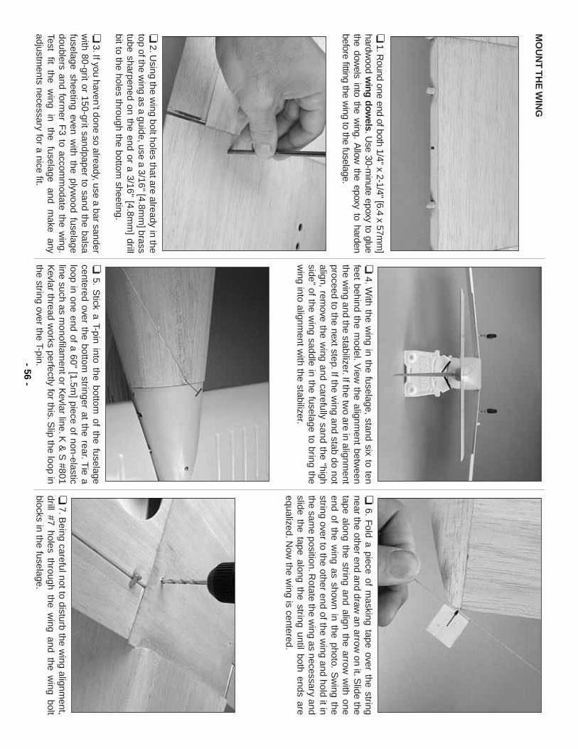
MO
UN
T T
HE
WIN
G
❏1.R
ound one end of both 1/4" x 2-1/4" [6.4 x 57mm
]hardw
ood wing dow
els.Use 30-m
inute epoxy to gluethe dow
els into the wing.
Allow
the epoxy to hardenbefore fitting the w
ing to the fuselage.
❏2.U
sing the wing bolt holes that are already in the
top of the wing as a guide, use a 3/16" [4.8m
m] brass
tube sharpened on the end or a 3/16" [4.8mm
] drillbit to the holes through the bottom
sheeting.
❏3.If you haven’t done so already, use a bar sander
with 80-grit or 150-grit sandpaper to sand the balsa
fuselage sheeting even with the plyw
ood fuselagedoublers and form
er F3 to accom
modate the w
ing.Test
fit the
wing
in the
fuselage and
make
anyadjustm
ents necessary for a nice fit.
❏4.W
ith the wing in the fuselage, stand six to ten
feet behind the model.V
iew the alignm
ent between
the wing and the stabilizer.If the tw
o are in alignment
proceed to the next step.If the wing and stab do not
align, remove the w
ing and carefully sand the “highside”
of the wing saddle in the fuselage to bring the
wing into alignm
ent with the stabilizer.
❏5.
Stick a T-pin into the bottom
of the fuselagecentered over the bottom
stringer at the rear.Tie a
loop in one end of a 60" [1.5m] piece of non-elastic
line such as monofilam
ent or Kevlar line.K
& S
#801K
evlar thread works perfectly for this.S
lip the loop inthe string over the T-pin.
❏6.
Fold a piece of m
asking tape over the stringnear the other end and draw
an arrow on it.S
lide thetape along the string and align the arrow
with one
end of the wing as show
n in the photo.S
wing the
string over to the other end of the wing and hold it in
the same position.R
otate the wing as necessary and
slide the tape along the string until both ends areequalized.N
ow the w
ing is centered.
❏7.B
eing careful not to disturb the wing alignm
ent,drill #7 holes through the w
ing and the wing bolt
blocks in the fuselage.- 56
-
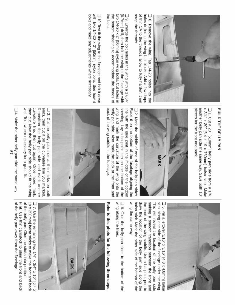
❏8.
Rem
ove the wing.
Tap 1/4-20 holes into theholes drilled in the w
ing bolt blocks.Add a few
dropsof thin C
A to the threads, allow
to fully harden, thenretap the threads.
❏9.E
nlarge the bolt holes in the wing w
ith a 17/64"[6.7m
m] drill, then bolt the w
ing to the fuselage with
two 1/4-20 x 2" [50m
m] nylon w
ing bolts.Cut holes in
the bottom sheeting to accom
modate the heads of
the bolts.
❏10.Test fit the w
ing to the fuselage and bolt it down
with tw
o 1/4-20 x 2" [50mm
] nylon bolts.S
ee how it
looks and make any adjustm
ents where necessary.
BU
ILD
TH
E B
EL
LY PA
N
❏1.C
ut a 20" [510mm
] belly p
an sid
efrom
a 1/4"x 3/4" x 30" [6.4 x 19 x 760m
m] balsa stick.
Make
another belly pan side the same w
ay.Save both 10"
pieces for the front and back.
❏2.M
ark the middle of one of the belly pan sides.
Place it on the bottom
of the fuselage aligning theline w
ith the glue joint in the middle of the bottom
sheeting.Lay a ballpoint pen on the bottom
of thew
ing and mark the curvature of the w
ing onto thebelly pan side.
Also m
ark the stick at the front andback of the w
ing saddle in the fuselage.
❏3.
Cut the belly pan side at the m
arks on bothends, then cut it on the curvature line you m
arked.R
eposition the
belly pan
side and
mark
anothercurvature line, then cut again.
Once m
ore, mark,
then cut.N
ow the belly pan side should fit the w
ingw
ell.Trim w
here necessary for a good fit.
❏4.M
ake the other belly pan side the same w
ay.
❏5.P
in a leftover 3/16" x 3/16" [4.8 x 4.8mm
] balsastick along one side of the fuselage under the w
ing.T
his will reveal the location of the belly pan side
making a sm
ooth transition between the front and
the back of the wing saddle.
Use a ballpoint pen to
draw the location of the belly pan side along the
balsa stick.Mark the other side of the bottom
of thew
ing the same w
ay.
❏6.
Glue the belly pan sides to the bottom
of thew
ing along the lines.
Refer to
this p
ho
to fo
r the fo
llow
ing
three step
s.
❏7.U
se the remaining tw
o 1/4" x 3/4" x 10" [6.4 x19 x 250m
m] balsa sticks to m
ake the front and backof the belly pan.G
lue the sticks into position.H
int:
Use thin cardstock to shim
the front and backof the belly pan aw
ay from the fuselage.
- 57-
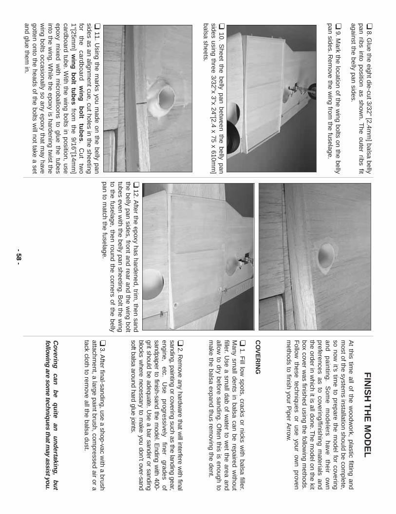
❏8.G
lue the eight die-cut 3/32" [2.4mm
] balsa bellypan ribs into position as show
n.T
he outer ribs fitagainst the belly pan sides.
❏9.M
ark the location of the wing bolts on the belly
pan sides.Rem
ove the wing from
the fuselage.
❏10.
Sheet the belly pan betw
een the belly pansides using three 3/32"x 3"x 24"[2.4 x 75 x 610m
m]
balsa sheets.
❏11.
Using the m
arks you made on the belly pan
sides as an alignment cue, cut holes in the sheeting
for
the
ca
rdb
oa
rd
win
g
bo
lt tu
bes.
Cu
t tw
o1"[25m
m] w
ing
bo
lt tub
esfrom
the 9/16"[14mm
]cardboard tube.W
ith the wing bolts in position, use
epoxy mixed w
ith microballoons to glue the tubes
into the wing.W
hile the epoxy is hardening twist the
wing bolts occasionally so any epoxy that m
ay havegotten onto the heads of the bolts w
ill not take a setand glue them
in.
❏12.A
fter the epoxy has hardened, trim, then sand
the belly pan sides, front and rear and the wing bolt
tubes even with the belly pan sheeting.B
olt the wing
to the fuselage, then round the corners of the bellypan to m
atch the fuselage.
FIN
ISH
TH
E M
OD
EL
At this tim
e all of the woodw
ork, plastic fitting andm
ost of the systems installation should be com
plete,so now
it’s time to prepare the m
odel for coveringa
nd
p
ain
ting
.S
om
e
mo
de
lers
have
th
eir
own
preferences as to covering/finishing materials and
the order in which it is all done.T
he model on the kit
box cover was finished using the follow
ing methods.
Follow
these techniques or use your own proven
methods to finish your P
iper Arrow
.
CO
VE
RIN
G
❏1.
Fill low
spots, cracks or nicks with balsa filler.
Many sm
all dents in balsa can be repaired without
filler.U
se a small dab of w
ater to wet the area and
allow to dry before sanding.
Often this is enough to
make the balsa expand thus rem
oving the dent.
❏2.R
emove any hardw
are that will interfere w
ith finalsanding, painting or covering such as the landing gear,engine,
etc.U
se progressively
finer grades
ofsandpaper to finish-sand the m
odel.Ending w
ith 400-grit should be adequate.U
se a bar sander or sandingblocks w
here necessary to make you don’t over-sand
soft balsa around hard glue joints.
❏3.A
fter final-sanding, use a shop-vac with a brush
attachment, a large paint brush, com
pressed air or atack cloth to rem
ove all the balsa dust.
Coverin
g
can
be
qu
ite an
u
nd
ertaking
,bu
tfollow
ing are some techniques that m
ay assist you.
- 58-
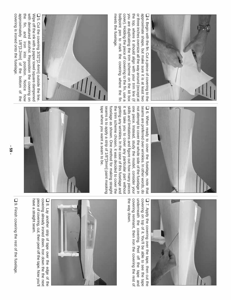
❏4.B
egin with the fin.C
ut a piece of covering to theapproxim
ate shape, but make sure it is at least tw
oor three inches oversize all the w
ay around (except atthe top, w
here it should align with your trim
line (ifyou are duplicating the trim
scheme on the kit box
cover).Holding the piece of covering to the fin, use a
ballpoint pen to mark the covering w
here the finm
eets the fuselage.
❏5.C
ut the covering 3/32"[2.4mm
] outside the line.W
ipe off the ink with a paper tow
el square dampened
with denatured alcohol.
Reposition the covering on
the
fin
, a
nd
iro
n
into
p
ositio
n.
No
tice
how
approximately
1/8"[3.2mm
] of
the bottom
of
thecovering is ironed onto the fuselage.
❏6.
When ready to cover the fuselage, note that
seams are preferred over w
rinkles.In other words, do
not attempt to cover the w
hole side of the fuselage inone piece.
Instead, study the model, consider your
skills and limitations and figure out how
many pieces
it will take you to cover any particular part w
ithoutgetting any w
rinkles.In the case of this fuselage andthe trim
scheme chosen, it w
as decided to cover thefuselage as show
n.One m
ethod for making straight
seams is to apply a strip of 1/8"[3m
m] paint m
askingtape w
here you want a seam
to be.
❏7.
Apply the covering over the tape, then cut the
covering on top of it.You’ll be able to see the tapeunderneath
the covering.
Peel
off the
tape and
covering remnant, then iron the covering the rest of
the way dow
n.
❏8.
Lay another strip of tape over the edge of thecovering already ironed dow
n.Iron down the the next
piece of covering, cut, then peel off the tape.Now
you’llhave a straight seam
.
❏9.F
inish covering the rest of the fuselage.- 59
-
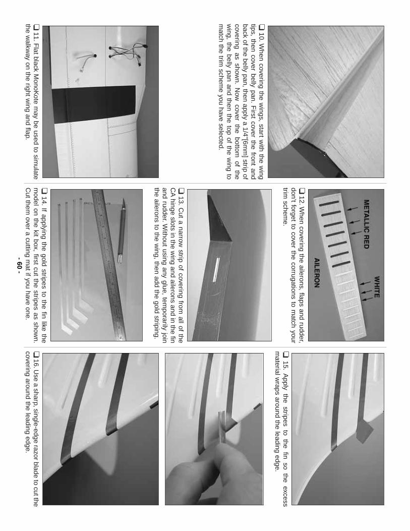
❏10.W
hen covering the wings, start w
ith the wing
tips, then cover belly pan.F
irst cover the front andback of the belly pan, then apply a 1/4"[6m
m] strip of
covering as shown.
Now
cover the bottom of the
wing, the belly pan and then the top of the w
ing tom
atch the trim schem
e you have selected.
❏11.F
lat black MonoK
ote may be used to sim
ulatethe w
alkway on the right w
ing and flap.
❏12.W
hen covering the ailerons, flaps and rudder,don’t forget to cover the corrugations to m
atch yourtrim
scheme.
❏13.
Cut a narrow
strip of covering from all of the
CA
hinge slots in the wing and ailerons and in the fin
and rudder.Without using any glue, tem
porarily jointhe ailerons to the w
ing, then add the gold striping.
❏14.
If applying the gold stripes to the fin like them
odel on the kit box, first cut the stripes as shown.
Cut them
over a cutting mat if you have one.
❏15.
Apply the stripes to the fin so the excess
material w
raps around the leading edge.
❏16.U
se a sharp, single-edge razor blade to cut thecovering around the leading edge.
- 60-
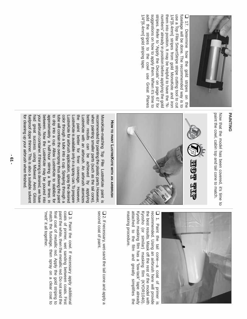
❏17.
Determ
ine how
the
gold stripes
on the
fuselage will be done.T
he recomm
ended way is to
use a Top Flite S
martS
tripe stripe cutting tool to cut1/4"[6.4m
m] stripes from
gold MonoK
ote and ironthem
into position.It may be helpful to have the “N
-num
bers”already in position before applying the goldstripes.
Refer to “A
pply the Decals”
on page 67 forsuggestions on how
to apply them.W
hen it’s time to
add the
stripes to
the cow
l use
Great
Planes
1/4"[6.4mm
] gold striping tape.
PAIN
TIN
G
Now
that the model has been covered, it’s tim
e topaint the cow
l, cabin top and tail cone to match.
❏1.
Paint
the tail
cone—a
coat of
primer
isrecom
mended.
Using an airbrush here w
ill providethe best results.M
ask off the rest of the model w
ithK
yosho (or
similar)
masking
film
(KY
OR
1040).K
yosho masking film
has a “low-tack”
tape alreadyattached
to the
film
and greatly
simplifies
them
asking procedure.
❏2.If necessary, w
et-sand the tail cone and apply asecond coat of paint.
❏3.
Paint the cow
l.If necessary apply additional
coats of primer, w
et sanding between coats.
First
paint the white, then the m
etallic red.Do not sand the
final coat of metallic red.
Apply the gold striping to
match the fuselage, then spray on a clear coat to
“melt”
it all together.
HO
WTO
PAIN
TL
US
TR
EKO
TE
WIT
HA
NA
IRB
RU
SH
MonoK
ote-matching Top
Flite
LustreKote
paint is
recomm
ended for painting the plastic parts.How
ever,w
hen painting smaller parts (such as the tail cone),
better results
can be
achieved by
applyingLustreK
ote with an airbrush.
An airbrush atom
izesthe
paint better
for finer
coverage.H
owever,
LustreKote is available only in a spray can.To prepare
LustreKote for airbrush application, spray the desired
color through a tube into a cup.Spraying through a
tube will contain the overspray thus allow
ing the paintto drip into a cup.
Allow
LustreKote to stabilize for
approximately
a half-hour
stirring a
few
times
inbetw
een.N
ow the LustreK
ote may be poured into
your airbrush container.If thinning is desired, we have
had great
success using
Midw
est A
ero G
lossfuelproof dope thinner.T
his is also a suitable solventfor cleaning up your airbrush w
hen finished.
- 61-
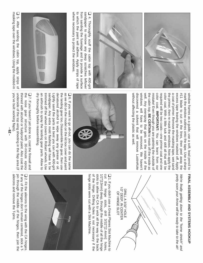
❏4.
Thoroughly scuff the cabin top w
ith 400-gritsandpaper to rem
ove any deep scratches leftoverfrom
sanding the fuselage and to provide a surfaceto w
hich the paint will adhere.
Apply strips of tape
where necessary to protect the w
indows.
❏5.
After sanding the cabin top, apply strips of
masking tape over the w
indows.U
sing the molded-in
window
frames as a guide, use a soft, lead pencil to
mark the w
indow outlines onto the tape.U
se a sharp#11 blade to cut on the lines, then peel aw
ay theexcess tape leaving the w
indows m
asked off.A
pplya coat of prim
er.Rem
ove the masking tape, w
et sandthe prim
er, then re mask the w
indows.N
ow apply the
color coat.With a little luck and skill all that w
ill berequired w
ill be two coats—
one primer coat and one
color coat.IM
PO
RTA
NT:
You can learn from our
mistake! E
ven though you are painting the outside ofthe cabin top, B
E C
ER
TAIN
to mask off the inside as
well.
Any overspray that gets on the inside of the
window
s w
ill have
to be
removed.
We
haven’tdiscovered
a solvent
that w
ill rem
ove LustreK
otew
ithout affecting the plastic as well.
❏6.If you w
ant to go all-out, you can do the same
as we did on the m
odel on the kit box cover and paintthe landing gear too.D
isassemble the gear, then use
denatured alcohol to wipe aw
ay any grease or oil.Lightly sand the parts as best you can w
ith 400-gritsandpaper.
Any extra m
old flashing will have to be
trimm
ed off the wheel covers on R
obart wheels.U
sean airbrush to spray the landing gear parts.A
llow to
dry thoroughly before reassembling.
❏7.If you haven’t yet done so, coat the firew
all andthe
nose gear
structure w
ith 30-m
inute epoxy
thinned with alcohol or fuelproof paint.A
lso coat theunderside of the top w
ing sheeting in the flap area (ifyou’ve built w
orking flaps).
FIN
AL
AS
SE
MB
LY A
ND
SY
ST
EM
S H
OO
KU
P
We’re finally getting dow
n to the “home stretch”
andpretty soon your A
rrow w
ill be ready to take to the air!
❏1.If you didn’t use a G
reat Planes S
lot Machine to
cut
the
h
ing
e
slots,
drill
3/3
2"[2
.4m
m]
ho
les,
1/2"[13mm
] deep, through the middle of all the hinge
slots to allow the C
A to w
ick all the way to the back
of the hinge.D
rilling holes is not necessary if thehinge slots w
ere cut with a S
lot Machine.
❏2.F
it the ailerons to the wing w
ith the CA
hinges.If any of the hinges don’t rem
ain centered, stick a T-pin through the m
iddle of the hinges, then join theailerons and rem
ove the T-pins.- 62
-
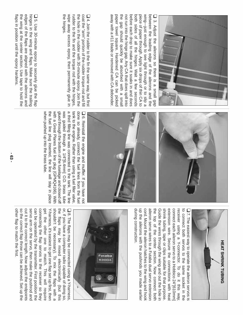
❏3.
Adjust the ailerons so there is a sm
all gapbetw
een the leading edge of the ailerons and thew
ing—just enough to see light through or to slip a
piece of paper through.Apply six drops of thin C
A to
both sides of all the hinges.W
ait a few seconds
before each drop to make sure it soaks in and does
not run into the hinge gap.Any C
A that does spill into
the gap should quickly be absorbed with a sm
allpaper tow
el square.H
ardened CA
can be pickedaw
ay with a #11 blade or rem
oved with C
A debonder.
❏4.Join the rudder to the fin the sam
e way, but first
coat the “arm”portion of the rudder torque rod and fill
the hole in the rudder with 30-m
inute epoxy.Join therudder to the fin and the torque rod w
ith the hinges,w
ipe away excess epoxy, then perm
anently glue inthe hinges.
❏5.U
se 30-minute epoxy to securely glue the flap
hinges in the wing and flaps.
Make sure the trailing
edges of the flaps are aligned with the ailerons and
the wing at the center section.U
se tape to hold theflaps in position until the epoxy hardens.
❏6.R
einstall the engine and muffler.If you have not
done so already, connect the fuel lines from the fuel
tank to the engine.Rather than using a fuel filler valve,
a third filling line was connected to the tank.T
he linew
as guided through a 1/4"[6.4mm
] O.D
.brass tube
glued through the bottom of the fuselage and closed off
with a G
reat Planes fuel line plug (G
PM
Q4166).W
iththe fuel line plug inserted, the line w
ill stay in placew
hen pushed up into the brass tube.
❏7.T
he easiest way to operate the aileron servos is
to connect both servos to the same socket in the
receiver using
a Y-connector.To
do it
this w
ay,connect each aileron servo to a H
obbico 24"[610mm
]extension w
ire.S
ecure the connections with heat
shrink tubing, tape or clips suitable for that purpose.G
uide the wires through the w
ing and out the hole inthe top of the center section.
Now
connect bothaileron servo w
ires to a Futaba dual servo extension
cord.Mount the aileron hatches to the w
ing and hookup the ailerons w
ith the pushrods you made earlier
during construction.
❏8.T
he flaps may be connected using a Y-harness,
or, if you have a computer radio capable of doing so,
the flaps
may
be m
ixed electronically
(but this
shouldn’t be necessary).To m
ix the flaps with a
Y-harness, it’s easiest to get one flap set up first, theng
et
the
o
the
r o
ne
to
m
atch
.T
his
will
req
uire
connecting the flap servos to the receiver so theycan be operated by the transm
itter.First position the
servo arm on the servo, then m
ake the pushrod andcut it to the correct length.N
ow adjust the endpoints
so the correct flap throw can be achieved.S
et up theother flap to m
atch the first.- 63
-
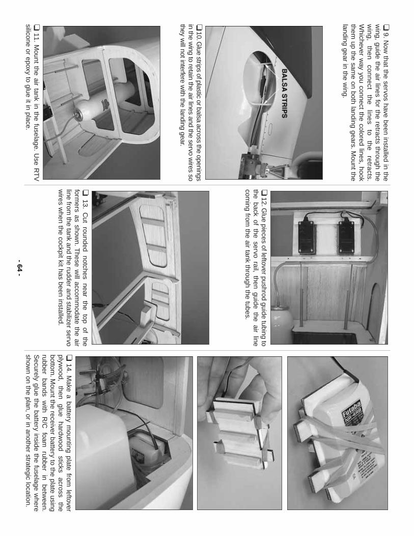
❏9.N
ow that the servos have been installed in the
wing, guide the air lines for the retracts through the
win
g,
the
n
con
ne
ct th
e
line
s to
th
e
retra
cts.W
hichever way you connect the colored lines, hook
them up the sam
e on both landing gears.Mount the
landing gear in the wing.
❏10.G
lue strips of plastic or balsa across the openingsin the w
ing to retain the air lines and the servo wires so
they will not interfere w
ith the landing gear.
❏11.
Mount the air tank in the fuselage.
Use R
TV
silicone or epoxy to glue it in place.
❏12.G
lue pieces of leftover pushrod guide tubing tothe back of the servo rail, then guide the air linecom
ing from the air tank through the tubes.
❏13.
Cut
rounded notches
near the
top of
theform
ers as shown.T
hese will accom
modate the air
line from the tank and the rudder and stabilizer servo
wires w
hen the cockpit kit has been installed.❏
14.M
ake a battery mounting plate from
leftoverplyw
ood, then
glue hardw
ood sticks
across the
bottom.M
ount the receiver battery to the plate usingrubber
bands w
ith R
/C
foam
rubber in
between.
Securely glue the battery inside the fuselage w
hereshow
n on the plan, or in another strategic location.- 64
-
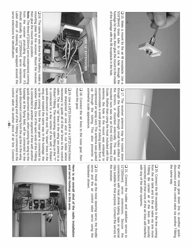
❏15.
Make a m
ount for the air fill receptacle.U
se a5/16"[8m
m]
brass tube
to cut
a hole
through the
fuselage for the valve, then glue the mount to the inside
of the fuselage with the fill receptacle in the hole.
❏16.T
he same as w
as done for the battery, make a
mounting plate for the receiver.
Mount the receiver,
then glue the mount into position.
No
te:The three 6"[150m
m] servo extensions com
ingfrom
the
receiver protruding
through form
er F
3should
actually be
12"[300mm
] servo
extensions.Label strips of m
asking tape wrapped around the
servo extensions for identification.
❏17.
The receiver antenna m
ay be routed down
through the fuselage through small holes drilled in
the form
ers, or
mounted
externally.T
he w
ay w
em
ounted ours was via an E
rnst #153 Antenna E
xitG
uide.Rather than using the hook included w
ith theantenna, the hole in the m
ount was enlarged to
accomm
odate a small piece of tubing (taken from
acom
pressed air spray can).The antenna w
as guidedu
p
thro
ug
h
the
tu
bin
g.
Th
is a
lso
pre
sen
ts a
somew
hat scale appearance.
❏18.
Connect the air lines to the nose gear, then
mount the gear.
❏19.U
se a 1/8"[3.2mm
] drill or a 1/8"[3.2mm
] brasstube
sharpened on
one end
to cut
holes w
herenecessary to guide all of the air lines to the controlvalve.T
he two “up”
lines in the wing are joined to a
Robart T-fitting.T
he remaining, open fitting on the “T
”is connected to a few
inches of line with a R
obartquick-disconnect on the end.T
he “down”
lines in thew
ing are treated the same w
ay.In the fuselage, the
up line coming from
the nose gear is connected toanother T-fitting.O
ne of the open ends of the T-fittingis connected to another segm
ent of line with another
quick-disconnect which, w
hen joining the wing to the
fuselage at the flying field, will be connected to the
quick-disconnect coming from
the up line in the wing.
The rem
aining end of the T-fitting is connected to thecontrol valve via another piece of air line.
Connect
the other nose gear down line to another quick-
disconnect and the control valve via another T-fittingthe sam
e way.
❏20.
Connect the fill receptacle to the line com
ingfrom
the air tank and to the air valve via one more
T-fitting.B
e certain
all of
the lines
are securely
connected and that none of the air lines will interfere
with any of the other system
s.
❏21.
Connect the rudder and stabilizer servos to
12
"[30
5m
m]
servo
exte
nsio
ns.
Se
cure
th
econnections w
ith heat shrink tubing, tape or specialclips suitable for that purpose.C
onnect the servos tothe receiver.
❏22.
Hook up the nose steering servo, the throttle
servo and
the air
control valve
servo using
thehardw
are shown.
Here is an
overall sho
t of th
e radio
installatio
nan
d servo
ho
oku
p in
this area.
- 65-
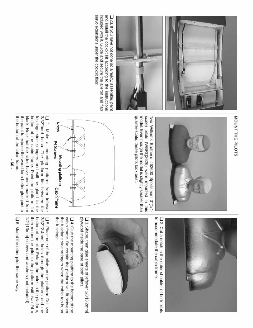
❏23.If you have not done so already, assem
ble, paintand install the cockpit kit according to the instructionsincluded w
ith it.Guide and secure the aileron and flap
servo extensions under the cockpit floor.
MO
UN
T T
HE
PIL
OT
S
Two W
illiams B
rother’s #62600 Sportsm
an 3"(1/4-scale)
pilots (W
BR
Q2626)
were
mounted
in this
model.E
ven though the model is slightly sm
aller thanquarter-scale, these pilots look best.
❏1.
Make
a m
ounting platform
from
leftover
3/32"hard balsa.
The
platform
fits betw
een the
fuselage side
stringers and
will
be glued
to the
bottom of the cabin fram
e.P
aint the platform flat
black.N
ote that the sides have been masked from
the paint to expose the wood for a better glue joint to
the bottom of the cabin fram
e.
❏2.C
ut a notch in the outer shoulder of both pilotsto accom
modate the cabin fram
e.
❏3.S
hape, then glue sheets of leftover 1/8"[3.2mm
]plyw
ood inside the base of both pilots.
❏4.G
lue the mounting platform
to the bottom of the
cabin frame.B
e certain the platform w
ill fit between
the fuselage side stringers when the cabin top is on
the fuselage.
❏5.P
lace one of the pilots on the platform.D
rill two
3/32"[2.4mm
] holes through the platform and the
bottom of the pilot.E
nlarge the holes in the platform,
then mount the pilot to the platform
with tw
o #4 x1/2"[13m
m] screw
s and washers (not included).
❏6.M
ount the other pilot the same w
ay.- 66
-
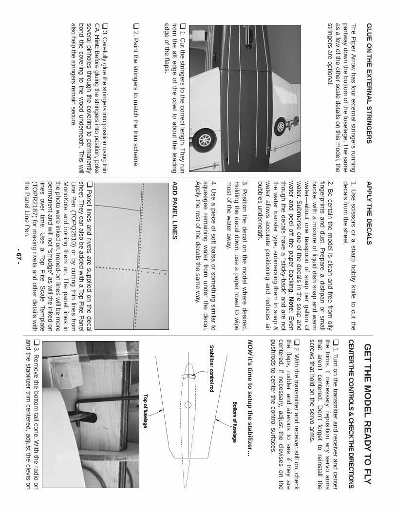
GL
UE
ON
TH
E E
XT
ER
NA
L S
TR
ING
ER
S
The P
iper Arrow
has four external stringers runningpartw
ay down the bottom
of the fuselage.The sam
eas a few
of the other scale details on this model, the
stringers are optional.
❏1.C
ut the stringers to the correct length.They run
from the aft edge of the cow
l to about the leadingedge of the flaps.
❏2.P
aint the stringers to match the trim
scheme.
❏3.C
arefully glue the stringers into position using thinC
A.H
int:Before gluing the stringers into position, poke
several pinholes through the covering to permanently
bond the covering to the wood underneath.
This w
illalso help the stringers rem
ain secure.
AP
PLY
TH
E D
EC
AL
S
1.U
se scissors or a sharp hobby knife to cut thedecals from
the sheet.
2.B
e certain the model is clean and free from
oilyfingerprints and dust.
Prepare a dishpan or sm
allbucket w
ith a mixture of liquid dish soap and w
armw
ater—about one teaspoon of soap per gallon of
water.S
ubmerse one of the decals in the soap and
water and peel off the paper backing.
No
te:E
venthough the decals have a “sticky-back”
and are notthe w
ater transfer type, submersing them
in soap &w
ater allows accurate positioning and reduces air
bubbles underneath.
3.P
osition the decal on the model w
here desired.H
olding the decal down, use a paper tow
el to wipe
most of the w
ater away.
4.Use a piece of soft balsa or som
ething similar to
squeegee remaining w
ater from under the decal.
Apply the rest of the decals the sam
e way.
AD
D PA
NE
L L
INE
S
❏P
anel lines and rivets are supplied on the decalsheet.T
hey can also be added with a Top F
lite Panel
Line Pen (TO
PQ
2510) or by cutting thin lines fromM
onoKote and ironing them
on.T
he panel lines inthe photo w
ere inked on.Ironed-on lines will be m
oreperm
anent and will not “sm
udge”as will the inked-on
lines over
time.
Use
a Top F
lite S
cale Template
(TOP
R2187) for m
aking rivets and other details with
the Panel Line P
en.
GE
T T
HE
MO
DE
L R
EA
DY
TO F
LY
CE
NTE
R TH
E C
ON
TRO
LS &
CH
EC
K TH
E D
IRE
CTIO
NS
❏1.Turn on the transm
itter and receiver and centerthe trim
s.If necessary, reposition any servo arm
sthat
aren’t centered.
Don’t
forget to
reinstall the
screws that hold on the servo arm
s.
❏2.W
ith the transmitter and receiver still on, check
the flaps, rudder and ailerons to see if they arecentered.
If necessary, adjust the clevises on thepushrods to center the control surfaces.
NO
Wit’s tim
e to setu
p th
e stabilizer…
❏3.R
emove the bottom
tail cone.With the radio on
and the stabilizer trim centered, adjust the clevis on
Stab
ilizer
- 67-
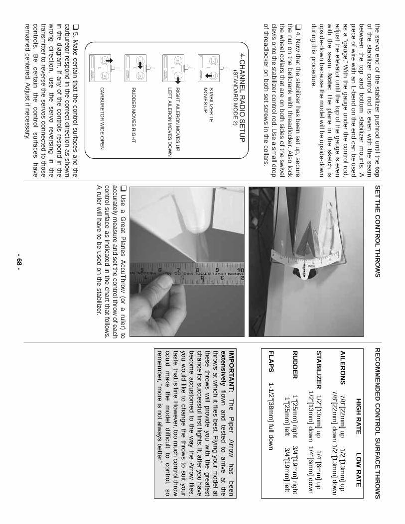
the servo end of the stabilizer pushrod until the top
of the stabilizer control rod is even with the seam
between the top and bottom
stabilizer mounts.
Apiece of w
ire with an L-bend on the end can be used
as a “gauge.”W
ith the gauge under the control rod,adjust the elevator until the top of the gauge is evenw
ith the seam.
No
te:T
he plane in the sketch isupside-dow
n because the model w
ill be upside-down
during this procedure.
❏4.N
ow that the stabilizer has been set up, secure
the nut on the bellcrank with threadlocker.A
lso lockthe w
heel collars that are on both sides of the swivel
clevis onto the stabilizer control rod.Use a sm
all dropof threadlocker on both set screw
s in the collars.
❏5.M
ake certain that the control surfaces and thecarburetor respond in the correct direction as show
nin the diagram
.If any of the controls respond in thew
rong direction,
use the
servo reversing
in the
transmitter to reverse the servos connected to those
controls.B
e certain
the control
surfaces have
remained centered.A
djust if necessary.
SE
T T
HE
CO
NT
RO
L T
HR
OW
S
❏U
se a Great P
lanes AccuT
hrow (or a ruler) to
accurately measure and set the control throw
of eachcontrol surface as indicated in the chart that follow
s.A
ruler will have to be used on the stabilizer.
RE
CO
MM
EN
DE
D C
ON
TR
OL
SU
RFA
CE
TH
RO
WS
IMP
OR
TAN
T:T
he
P
ipe
r A
rrow
ha
s b
ee
nexten
sivelyflow
n and
tested to
arrive at
thethrow
s at which it flies best.F
lying your model at
these throws w
ill provide you with the greatest
chance for successful first flights.If, after you havebecom
e accustomed to the w
ay the Arrow
flies,you w
ould like to change the throws to suit your
taste, that is fine.How
ever, too much control throw
could m
ake the
model
difficult to
control, so
remem
ber, “more is not alw
ays better.”
HIG
H R
AT
EL
OW
RA
TE
AIL
ER
ON
S7/8"[22m
m] up
1/2"[13mm
] up7/8"[22m
m] dow
n1/2"[13m
m] dow
n
STA
BIL
IZE
R1/2"[13m
m] up
1/4"[6mm
] up1/2"[13m
m] dow
n 1/4"[6m
m] dow
n
RU
DD
ER
1"[25mm
] right 3/4"[19m
m] right
1"[25mm
] left 3/4"[19m
m] left
FL
AP
S1-1/2"[38m
m] full dow
n
4-CH
AN
NE
LT
RA
NS
MIT
TE
R
TR
AN
SM
ITT
ER
4-CH
AN
NE
L
TR
AN
SM
ITT
ER
4-CH
AN
NE
L
TR
AN
SM
ITT
ER
4-CH
AN
NE
L
- 68-
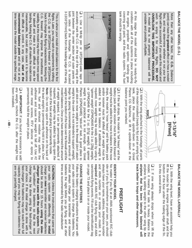
BA
LA
NC
E T
HE
MO
DE
L(C
.G.)
At this stage the m
odel should be in ready-to-flycondition w
ith all of the systems in place including
the engine,
propeller and
spinner, landing
gear,covering and paint, and the radio system
.The fuel
tank should be empty.
❏1.
Use
a felt-tip
pen or
1/8"[3mm
]-wide
tape to
accurately mark the C
.G.on the top of the w
ing at thejoint betw
een the center section and outer panels onboth
sides of
the fuselage.
The
C.G
.is
located 3-13/16"[97m
m] back from
the leading edge of the wing.
❏2.W
ith the wing attached to the fuselage, all parts
of the model installed (ready to fly) and an em
pty fueltank,
place the
model
upside-down
on a
Great
Planes C
G M
achine, or lift it upside-down at the
balance point you marked.
❏3.If the tail drops, the m
odel is “tail heavy”and the
battery pack and/or receiver must be shifted forw
ard orw
eight must be added to the nose to balance.If the nose
drops, the model is “nose heavy”
and the battery packand/or receiver m
ust be shifted aft or weight m
ust beadded to the tail to balance.
If additional weight is
required, nose weight m
ay be easily added by using a“spinner w
eight”(GP
MQ
4645 for the 1 oz.[28g] weight,
or GP
MQ
4646 for the 2 oz.[57g] w
eight).If spinner
weight is not practical or is not enough, use G
reatP
lanes (GP
MQ
4485) “stick-on”lead.
A good place to
add stick-on nose weight is to the firew
all (don’t attachw
eight to the cowl—
it is not intended to support weight).
Begin by placing increm
entally increasing amounts of
weight on the bottom
of the fuse over the firewall until the
model balances.O
nce you have determined the am
ountof w
eight required, it can be permanently attached.
Ifrequired, tail w
eight may be added by cutting open the
bottom of the fuse and gluing it perm
anently inside.N
ote:
Do not rely upon the adhesive on the back of
the lead weight to perm
anently hold it in place.Over
time,
fuel and
exhaust residue
may
soften the
adhesive and cause the weight to fall off.
Use #2
sheet m
etal screw
s, R
TV
silicone
or epoxy
toperm
anently hold the weight in place.
❏4.IM
PO
RTA
NT:
If you found it necessary to addany w
eight, recheck the C.G
.after the w
eight hasbeen installed.
BA
LA
NC
E T
HE
MO
DE
L L
AT
ER
AL
LY
❏1.W
ith the wing level, have an assistant help you
lift the model by the engine propeller shaft and the
bottom of the fuse under the trailing edge of the fin.
Do this several tim
es.
❏2.
If one wing alw
ays drops when you lift the
model,
it m
eans that
side is
heavy.B
alance the
airplane by adding weight to the other w
ing tip.A
nairp
lane
that
has
been
laterally
balan
ced
will
track better in
loo
ps an
d o
ther m
aneu
vers.
PR
EF
LIG
HT
IDE
NT
IFY
YO
UR
MO
DE
LN
o matter if you fly at an A
MA
sanctioned R/C
clubsite or if you fly som
ewhere on your ow
n, you shouldalw
ays have your name, address, telephone num
berand A
MA
number on or inside your m
odel.It is
requ
iredat all A
MA
R/C
club flying sites and AM
Asanctioned flying events.F
ill out the identification tagon page 73 and place it on or inside your m
odel.
CH
AR
GE
TH
E B
AT
TE
RIE
SFollow
the battery charging instructions that came w
ithyour radio control system
to charge the batteries.Youshould alw
ays charge your transmitter and receiver
batteries the night before you go flying, and at othertim
es as recomm
ended by the radio manufacturer
CA
UT
ION
:U
nless the instructions that came w
ithyour
radio system
state
differently, the
initial
charge on new
transmitter and receiver batteries
should be done for 15 hours usin
g th
e slow
-ch
arger th
at came w
ith th
e radio
system.T
hisw
ill “condition”
the batteries
so that
the next
charge may be done using the fast-charger of
your choice.If the initial charge is done w
ith afast-charger the batteries m
ay not reach their fullcapacity and you m
ay be flying with batteries that
are only partially charged.
[97mm
]
This is w
here your model should balance for the first
flights.Later, you may w
ish to experiment by shifting
the C.G
.up to 3/8"[10m
m] forw
ard or 3/8"[10mm
]back to change the flying characteristics.M
oving theC
.G.
forward
may
improve
the sm
oothness and
stability, but the model m
ay then require more speed
for takeoff and make it m
ore difficult to slow for
landing.Moving the C
.G.aft m
akes the model m
orem
aneuverable, but could also cause it to become
too difficult to control.In any case, start at the
recomm
ended balance point and do not at anytim
e balance the model outside the specified range.
More
than any
other factor,
theC
.G.
(balancepoint) can have the g
reatesteffect on how a m
odelflies, and m
ay determine w
hether or not your firstflight w
ill be successful.If you value this model and
wish
to enjoy
it for
many
flights, D
O
NO
TO
VE
RL
OO
K T
HIS
IM
PO
RTA
NT
P
RO
CE
DU
RE
.A
m
odel that
is not
properly balanced
will
beunstable and possibly unflyable.
- 69-
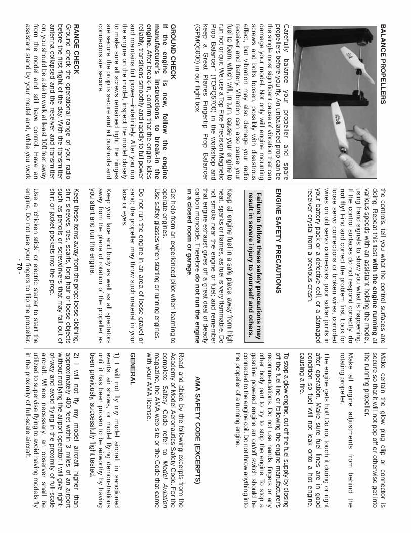
BA
LA
NC
E P
RO
PE
LL
ER
S
Ca
refu
lly b
ala
nce
yo
ur
pro
pe
ller
an
d
spa
repropellers before you fly.A
n unbalanced prop can bethe single m
ost significant cause of vibration that candam
age your model.
Not only w
ill engine mounting
screws and bolts loosen, possibly w
ith disastrouseffect, but vibration m
ay also damage your radio
receiver and battery.V
ibration can also cause yourfuel to foam
, which w
ill, in turn, cause your engine torun hot or quit.W
e use a Top Flite P
recision Magnetic
Prop B
alancer™
(TOP
Q5700) in the w
orkshop andkeep
a G
reat P
lanes F
ingertip P
rop B
alancer(G
PM
Q5000) in our flight box.
GR
OU
ND
CH
EC
KIf
the
eng
ine
is n
ew,
follo
w
the
eng
ine
man
ufactu
rer’s in
structio
ns
to
break-in
th
een
gin
e.A
fter break-in, confirm that the engine idles
reliably, transitions smoothly and rapidly to full pow
erand m
aintains full power—
indefinitely.After you run
the engine on the model, inspect the m
odel closelyto m
ake sure all screws rem
ained tight, the hingesare secure, the prop is secure and all pushrods andconnectors are secure.
RA
NG
E C
HE
CK
Ground check the operational range of your radio
before the first flight of the day.With the transm
itterantenna collapsed and the receiver and transm
itteron, you should be able to w
alk at least 100 feet away
from
the m
odel and
still have
control.H
ave an
assistant stand by your model and, w
hile you work
the controls, tell you what the control surfaces are
doing.Repeat this test w
ith th
e eng
ine ru
nn
ing
atvarious speeds w
ith an assistant holding the model,
using hand signals to show you w
hat is happening.If the control surfaces do not respond correctly, d
on
ot fly!
Find and correct the problem
first.Look forloose servo connections or broken w
ires, corrodedw
ires on old servo connectors, poor solder joints inyour battery pack or a defective cell, or a dam
agedreceiver crystal from
a previous crash.
EN
GIN
E S
AF
ET
Y P
RE
CA
UT
ION
S
Keep all engine fuel in a safe place, aw
ay from high
heat, sparks or flames, as fuel is very flam
mable.D
onot sm
oke near the engine or fuel;and rem
ember
that engine exhaust gives off a great deal of deadlycarbon m
onoxide.Therefore
do
no
t run
the en
gin
ein
a closed
roo
m o
r garag
e.
Get help from
an experienced pilot when learning to
operate engines.U
se safety glasses when starting or running engines.
Do not run the engine in an area of loose gravel or
sand;the propeller may throw
such material in your
face or eyes.
Keep your face and body as w
ell as all spectatorsaw
ay from the plane of rotation of the propeller as
you start and run the engine.
Keep these item
s away from
the prop:loose clothing,shirt sleeves, ties, scarfs, long hair or loose objectssuch as pencils or screw
drivers that may fall out of
shirt or jacket pockets into the prop.
Use a “chicken stick”
or electric starter to start theengine.D
o not use your fingers to flip the propeller.
Make
certain the
glow
plug clip
or connector
issecure so that it w
ill not pop off or otherwise get into
the running propeller.
Make
all engine
adjustments
from
behind the
rotating propeller.
The engine gets hot! D
o not touch it during or rightafter operation.
Make sure fuel lines are in good
condition so fuel will not leak onto a hot engine,
causing a fire.
To stop a glow engine, cut off the fuel supply by closing
off the fuel line or following the engine m
anufacturer’srecom
mendations.
Do not use hands, fingers or any
other body part to try to stop the engine.To stop a
gasoline powered engine an on/off sw
itch should beconnected to the engine coil.D
o not throw anything into
the propeller of a running engine.
AM
A S
AF
ET
Y C
OD
E (E
XC
ER
PT
S)
Read and abide by the follow
ing excerpts from the
Academ
y of Model A
eronautics Safety C
ode.For the
complete
Safety
Code
refer to
Model
Aviation
magazine, the A
MA
web site or the C
ode that came
with your A
MA
license.
GE
NE
RA
L
1) I
will
not fly
my
model
aircraft in
sanctionedevents, air show
s, or model flying dem
onstrationsuntil it has been proven to be airw
orthy by havingbeen previously, successfully flight tested.
2) I
will
not fly
my
model
aircraft higher
thanapproxim
ately 400 feet within 3 m
iles of an airportw
ithout notifying the airport operator.I will give right-
of-way and avoid flying in the proxim
ity of full-scaleaircraft.
Where
necessary, an
observer shall
beutilized to supervise flying to avoid having m
odels flyin the proxim
ity of full-scale aircraft.
Failure to
follo
w th
ese safety precau
tion
s may
result in
severe inju
ry to yo
urself an
d o
thers.
- 70-
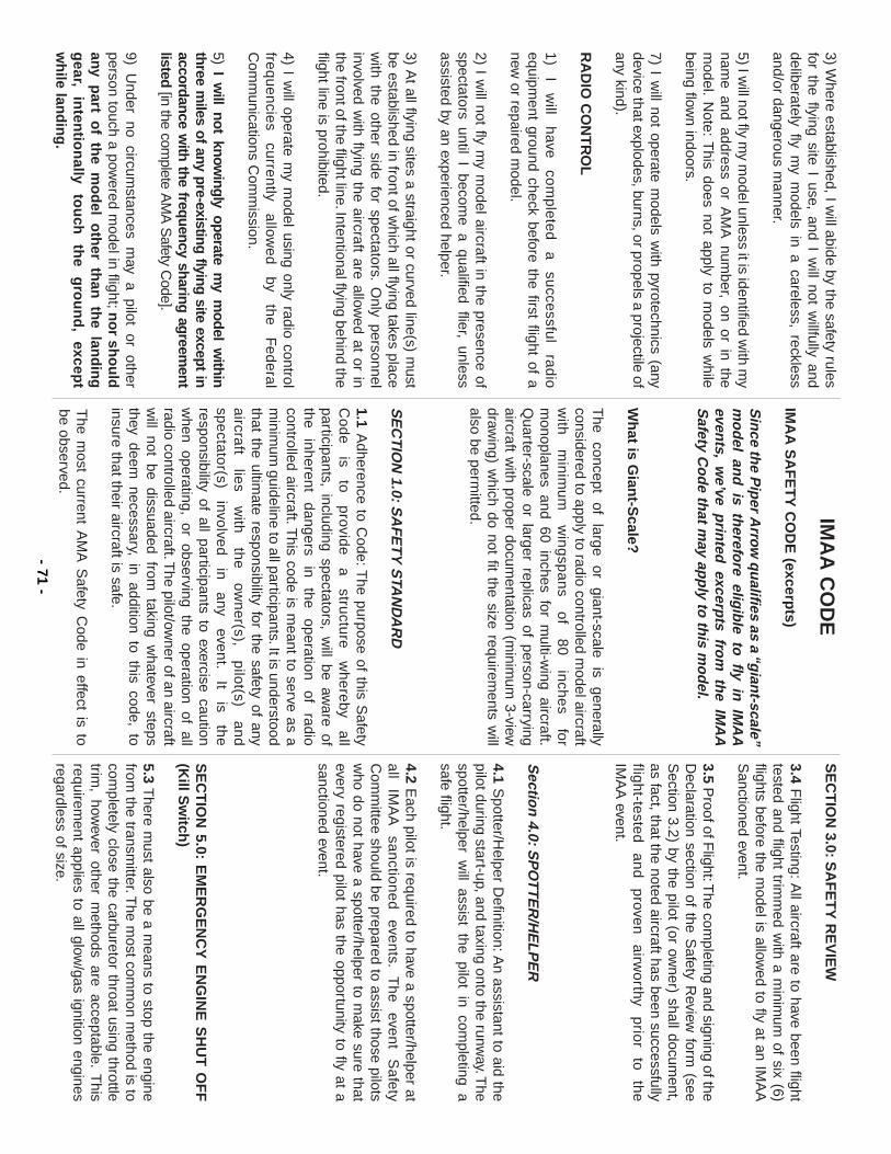
3) Where established, I w
ill abide by the safety rulesfor the flying site I use, and I w
ill not willfully and
deliberately fly my m
odels in a careless, recklessand/or dangerous m
anner.
5) I will not fly m
y model unless it is identified w
ith my
name and address or A
MA
number, on or in the
model.
Note:
This does not apply to m
odels while
being flown indoors.
7) I will not operate m
odels with pyrotechnics (any
device that explodes, burns, or propels a projectile ofany kind).
RA
DIO
CO
NT
RO
L
1)
I w
ill h
ave
com
ple
ted
a
su
ccessfu
l ra
dio
equipment ground check before the first flight of a
new or repaired m
odel.
2) I will not fly m
y model aircraft in the presence of
spectators until I become a qualified flier, unless
assisted by an experienced helper.
3) At all flying sites a straight or curved line(s) m
ustbe established in front of w
hich all flying takes placew
ith the other side for spectators.O
nly personnelinvolved w
ith flying the aircraft are allowed at or in
the front of the flight line.Intentional flying behind theflight line is prohibited.
4) I will operate m
y model using only radio control
freq
ue
ncie
s cu
rren
tly a
llowe
d
by th
e
Fe
de
ral
Com
munications C
omm
ission.
5) I will not know
ingly operate my m
odel within
three miles of any pre-existing flying site except in
accordance with the frequency sharing agreem
entlisted
[in the complete A
MA
Safety C
ode].
9) Under no circum
stances may a pilot or other
person touch a powered m
odel in flight;no
r sho
uld
any part o
f the m
od
el oth
er than
the lan
din
gg
ear,in
tentio
nally
tou
ch
the
gro
un
d,
except
wh
ile land
ing
.
IMA
A C
OD
E
IMA
A S
AF
ET
Y C
OD
E (excerp
ts)
Sin
ce the P
iper A
rrow q
ualifies as a “g
iant-scale”
mo
del an
d is th
erefore elig
ible to fly in
IMA
Aeven
ts,w
e’ve prin
ted excerp
ts from
the IM
AA
Safety C
od
e that m
ay app
ly to th
is mo
del.
Wh
at is Gian
t-Scale?
The
concept of
large or
giant-scale is
generallyconsidered to apply to radio controlled m
odel aircraftw
ith
min
imu
m
win
gsp
an
s o
f 8
0
inch
es
form
onoplanes and 60 inches for multi-w
ing aircraft.Q
uarter-scale or larger replicas of person-carryingaircraft w
ith proper documentation (m
inimum
3-viewdraw
ing) which do not fit the size requirem
ents will
also be permitted.
SE
CT
ION
1.0:SA
FE
TY
STA
ND
AR
D
1.1 Adherence to C
ode:The purpose of this S
afetyC
od
e
is to
p
rovide
a
stru
cture
w
he
reby
all
participants, including spectators, will be aw
are ofthe
inherent dangers
in the
operation of
radiocontrolled aircraft.T
his code is meant to serve as a
minim
um guideline to all participants.It is understood
that the ultimate responsibility for the safety of any
aircra
ft lie
s w
ith
the
ow
ne
r(s), p
ilot(s)
an
dsp
ecta
tor(s)
involve
d
in
any
even
t.It
is th
eresponsibility of all participants to exercise cautionw
hen operating, or observing the operation of allradio controlled aircraft.T
he pilot/owner of an aircraft
will not be dissuaded from
taking whatever steps
they deem necessary, in addition to this code, to
insure that their aircraft is safe.
The m
ost current AM
A S
afety Code in effect is to
be observed.
SE
CT
ION
3.0:S
AF
ET
Y R
EV
IEW
3.4 Flight Testing:A
ll aircraft are to have been flighttested and flight trim
med w
ith a minim
um of six (6)
flights before the model is allow
ed to fly at an IMA
AS
anctioned event.
3.5 Proof of F
light:The com
pleting and signing of theD
eclaration section of the Safety R
eview form
(seeS
ection 3.2) by the pilot (or owner) shall docum
ent,as fact, that the noted aircraft has been successfullyflig
ht-te
sted
a
nd
p
roven
a
irwo
rthy p
rior
to
the
IM
AA
event.
Sectio
n 4.0:S
PO
TT
ER
/HE
LP
ER
4.1 Spotter/H
elper Definition:A
n assistant to aid thepilot during start-up, and
taxing onto the runway.T
hespotter/helper w
ill assist the pilot in completing a
safe flight.
4.2E
ach pilot is required to have a spotter/helper atall
IMA
Asanctioned
events.T
he event
Safety
Com
mittee should be prepared to assist those pilots
who do not have a spotter/helper to m
ake sure thatevery registered pilot has the opportunity to fly at asanctioned event.
SE
CT
ION
5.0:E
ME
RG
EN
CY
EN
GIN
E S
HU
T O
FF
(Kill S
witch
)
5.3T
here must also be a m
eans to stop the enginefrom
the transmitter.T
he most com
mon m
ethod is tocom
pletely close the carburetor throat using throttletrim
, however other m
ethods are acceptable.T
hisrequirem
ent applies to all glow/gas ignition engines
regardless of size.- 71
-
SE
CT
ION
6.0:R
AD
IO R
EQ
UIR
EM
EN
TS
All transm
itters must be F
CC
type certified.
6.2F
CC
Technician or higher-class license requiredfor 6 m
eter band operation only.
The follow
ing recomm
endations are included in theS
afety Code not to police such item
s, but rather tooffer basic suggestions for enhanced safety.
It isexpected that IM
AA
mem
bers will avail them
selvesof
technological advances
as such
become
available, to promote the safety of all aircraft and
participants.
Servos need to be of a rating capable to handle the
loads that
the control
surfaces im
pose upon
theservos.
Standard servos are not recom
mended for
control surfaces.Servos should be rated heavy-duty
ounces of torque.For flight-critical control functions a
minim
um
of 45
inch/ounces of
torque should
beconsidered.
This should be considered a m
inimum
for sm
aller aircraft
and higher
torque servos
arestrongly encouraged for larger aircraft.
The use of
one servo for each aileron and one for each stabilizerhalf is strongly recom
mended.U
se of dual servos isalso recom
mended on larger aircraft.
On-board batteries should be, at a m
inimum
, 1000m
Ah up to 20 lbs., 1200 m
Ah to 30 lbs., 1800 m
Ah to
40 lbs., and 2000 mA
h over 40 lbs.flying weight.T
henum
ber and size of servos, size and loads on controlsurfaces, and added features should be consideredas an increase to these m
inimum
s.Batteries should
be able
to sustain
power
to the
onboard radio
components for a m
inimum
of one hour total flyingtim
e before recharging.
CH
EC
K L
IST
❏1.F
uelproof all areas exposed to fuel or exhaustresidue such as the firew
all and engine area,the w
ing saddle area, the cardboard wing bolt
tubes, wheel w
ells, etc.
❏2.C
heck the C.G
.according to the measurem
entsprovided in the m
anual.
❏3.B
e certain the battery and receiver are securelym
ounted.S
imply stuffing them
into place with
foam rubber is not sufficient.
❏4.E
xtend your receiver antenna and make sure it
has a strain relief inside the fuselage to keeptension off the solder joint inside the receiver.
❏5.B
alance your model laterally
as explained in the instructions.
❏6.U
se threadlocking compound to secure critical
fasteners such as the set screws that hold the
wheel axles to the struts, screw
s that hold theca
rbure
tor
arm
(if
ap
plica
ble),
screw-lo
ckpushrod connectors, etc.
❏7.A
dd a drop of oil to the axles so the wheels w
illturn freely.
❏8.M
ake sure all hinges are securelyglued in place.
❏9.R
einforce holes for wood screw
s with thin C
Aw
here appropriate
(servo m
ounting screw
s,cow
l mounting screw
s, etc.).
❏10.C
onfirm that all controls operate in the correct
direction and the throws are set up according
to the manual.
❏11.M
ake sure there are silicone retainers on allthe
clevises and
that all
servo arm
s are
secu
red
to
th
e
servo
s w
ith
the
screw
sincluded w
ith your radio.❏
12.Secure connections betw
een servo wires and
Y-connectors or
servo extensions,
and the
connection between your battery pack and the
on/off switch w
ith vinyl tape, heat shrink tubingor special clips suitable for that purpose.
❏13.M
ake sure any servo extension cords you may
have used do not interfere with other system
s(servo arm
s, pushrods, landing gear, etc.).❏
14.Secure the pressure tap (if used) to the m
ufflerw
ith high temp R
TV
silicone, thread lockingcom
pound or J.B.W
eld.❏
15.Make sure the fuel lines are connected and
are not kinked.❏
16.Use an incidence m
eter to check the wing for
twists and attem
pt to correct before flying.❏
17.Balance your propeller (and spare propellers).
❏18.T
ighten the propeller nut and spinner.❏
19.Place your nam
e, address, AM
A num
ber andtelephone num
ber on or inside your model.
❏20.C
ycle your receiver battery pack (if necessary)and m
ake sure it is fully charged.❏
21.If you wish to photograph your m
odel, do sobefore your first flight.
❏22.R
ange check your radio when you get to the
flying field.
FLY
ING
The A
rrow is a great-flying m
odel that flies smoothly
and predictably.
The
Arrow
does
not, how
ever,p
osse
ss th
e
self-re
covery ch
ara
cteristics
of
aprim
ary R/C
trainer and should be flown only by
experienced R/C
pilots.
Fu
el Mixtu
re Ad
justm
ents
A
fully
cowle
d
en
gin
e
may
run
a
t a
h
igh
er
temperature than an un-cow
led engine.For this
During the last few
mom
ents of preparation yourm
ind
m
ay b
e
elsew
he
re
an
ticipa
ting
th
eexcitem
ent of the first flight.Because of this, you
may be m
ore likely to overlook certain checks andprocedures that should be perform
ed before them
odel is flown.
To help avoid this, a checklist isprovided to m
ake sure these important areas are
no
t ove
rloo
ked
.M
any
are
cove
red
in
th
einstruction m
anual, so where appropriate, refer to
the manual for com
plete instructions.B
e sure tocheck the item
s off as they are completed.
- 72-
reason, the fuel mixture should be richened so the
engine runs at about 200 rpm below
peak speed.By
running the engine slightly rich, you will help prevent
dead-stick landings caused by overheating.
TAK
EO
FF
Before you get ready to takeoff, see how
the model
handles on the ground by doing a few practice runs
at low
speed
son the runw
ay.Make sure the m
odelrolls straight dow
n the runway and m
ake any trimadjustm
ents necessary to get it to go straight.If youneed to take a break before the m
aiden flight, shutoff the engine and bring the m
odel back into the pits.Top off the fuel, then check all fasteners and controllinkages for peace of m
ind.
Rem
ember to takeoff into the w
ind.W
hen ready,point
the m
odel straight
down
the runw
ay, then
gradually advance the throttle.Gain as m
uch speedas your runw
ay and flying site will practically allow
before gently applying up elevator and lifting them
odel into the air.A
small am
ount of right rudderm
ay be required to correct engine torque to keep thew
ings level.Be sm
ooth on the elevator stick, allowing
the model to establish a g
entle
climb to a safe
altitude before turning into the traffic pattern.
FL
IGH
TF
or reassurance and to keep an eye on other traffic,it is a good idea to have an assistant on the flight linew
ith you.Tell him to rem
ind you to throttle back oncethe plane gets to a com
fortable altitude.W
hile fullthrottle is usually desirable for takeoff, m
ost models
fly more sm
oothly at reduced speeds.
Take it easy for the first few flights, gradually getting
acquainted with the m
odel as you gain confidence.A
djust the trims to m
aintain straight-and-level flight.A
fter flying around for a while, and w
hile still at a safealtitude w
ith plenty of fuel, practice slow flight and
extend the flaps to see how the m
odel reacts.A
ddpow
er to see how the m
odel climbs as w
ell.Continue
to fly around, working the controls and executing
various maneuvers and m
aking mental notes (or
having your assistant write them
down) of w
hat trimor C
.G.
changes may be required to fine tune the
model so it flies the w
ay you like.Mind your fuel level,
but use this first flight to become fam
iliar with your
model before landing.
LA
ND
ING
To initiate a landing approach, lower the throttle w
hile onthe dow
nwind leg, allow
the model to slow
, then extendthe flaps.A
llow the nose of the m
odel to pitch downw
ardto gradually bleed off altitude.C
ontinue to lose altitude,but m
aintain airspeed by keeping the nose down as you
turn onto the crosswind leg.M
ake your final turn toward
the runway (into the w
ind) keeping the nose down to
maintain airspeed and control.W
hen landing with flaps,
keep a few additional “clicks”
of throttle to maintain
airspeed.Level the attitude when the m
odel reaches therunw
ay threshold, modulating the throttle as necessary
to maintain your glide path and airspeed.
If you aregoing to overshoot, sm
oothly advance the throttle, allowthe m
odel to gain speed, retract the flaps and climb out
to make another attem
pt.When you’re ready to m
akeyour landing flare and the m
odel is a foot or so off thedeck, sm
oothly increase up elevator until it the wheels
gently touch down.
Once the m
odel is on the runway
and has lost flying speed, relax the elevator and taxi them
odel back.
Exam
ine the
model
and m
ake any
mechanical adjustm
ents necessary so the trims can be
returned to center.
One final note about flying your m
odel.Have a goal or
flight plan in mind for every flight.T
his can be learning anew
maneuver(s), im
proving a maneuver(s) you already
know, or learning how
the model behaves in certain
conditions (such as on high or low rates).T
his is notnecessarily to im
prove your skills (though it is never abad idea!), but m
ore importantly so you do not surprise
yourself by
impulsively
attempting
a m
aneuver and
suddenly finding that you’ve run out of time, altitude or
airspeed.E
very maneuver should be deliberate, not
impulsive.
For example, if you’re going to do a loop,
check your altitude, mind the w
ind direction (anticipatingrudder corrections that w
ill be required to maintain
heading), remem
ber to throttle back at the top, andm
ake certain you are on the desired rates (high/lowrates).
A flight plan greatly reduces the chances of
crashing your model just because of poor planning and
impulsive m
oves.Rem
ember to think.
Have a b
all! Bu
t always stay in
con
trol an
d fly in
a safe man
ner.
CA
UT
ION
(TH
IS
AP
PL
IES
T
O
AL
LR
/CA
IRP
LAN
ES
):If,
while
flying, you
notice an
alarming or unusual sound such as a low
-pitched“buzz,”
this may indicate control surface flutter.
Flutter occurs w
hen a control surface (such as anaileron or elevator) or a flying surface (such as aw
ing or stab) rapidly vibrates up and down (thus
causing the
noise).In
extreme
cases, if
notdetected im
mediately, flutter can actually cause
the control surface to detach or the flying surfaceto fail, thus causing loss of control follow
ed by anim
pending crash.The best thing to do w
hen flutteris detected is to slow
the model im
med
iatelyby
reducing pow
er, then
land as
soon as
safelypossible.
Identify which surface fluttered (so the
problem m
ay be resolved) by checking all theservo
gromm
ets for
deterioration or
signs of
vibration.M
ake certain all pushrod linkages aresecure and free of play.If it fluttered once, undersim
ilar circumstances it w
ill probably flutter againunless the problem
is fixed.S
ome things w
hichcan cause flutter are;
Excessive hinge gap;
Not
mounting control horns solidly;
Poor fit of clevis
pin in horn;Side-play of w
ire pushrods caused bylarge bends;
Excessive free play in servo gears;
Insecure servo mounting;
and one of the most
preva
len
t ca
use
s o
f flu
tter;
Flyin
g
an
ove
r-pow
ered model at excessive speeds.
- 73-
This model belongs to:
Name
Address
City, State Zip
Phone number
AMA number
Fill in andplace in
your model.
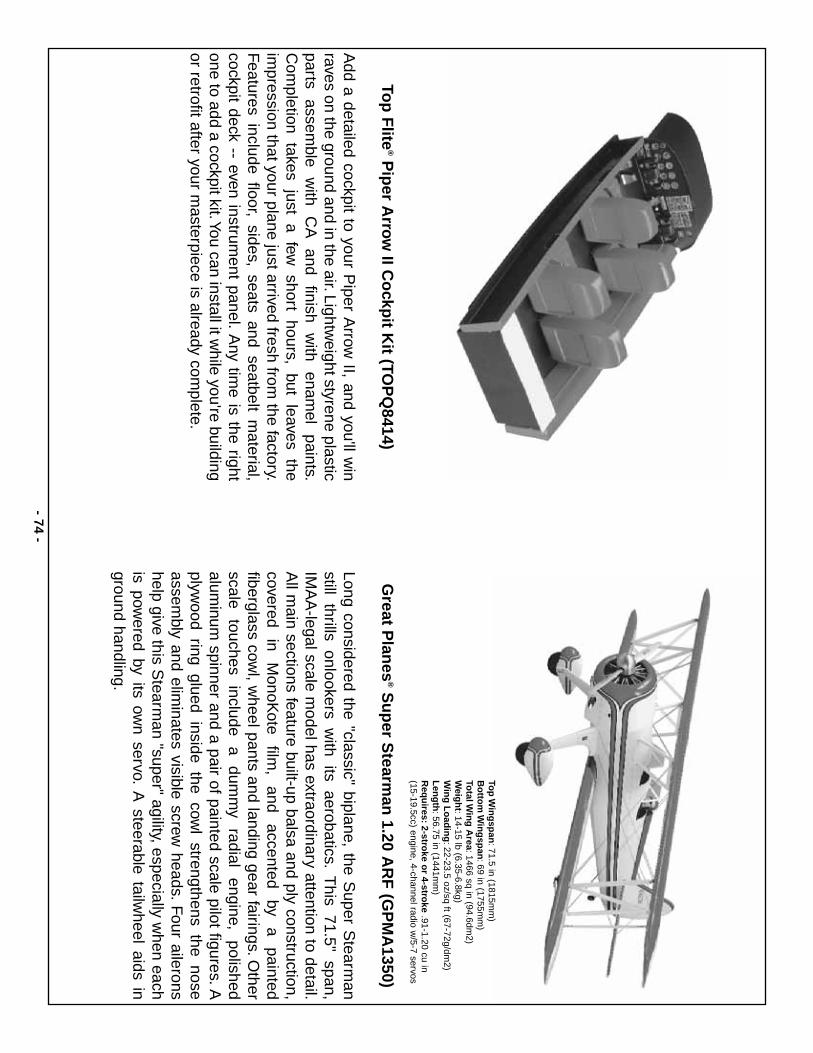
- 74-
Top
Flite
®P
iper A
rrow
II Co
ckpit K
it (TOP
Q8414)
Add a detailed cockpit to your P
iper Arrow
II, and you'll win
raves on the ground and in the air.Lightweight styrene plastic
parts assem
ble w
ith C
A
and finish
with
enamel
paints.C
ompletion takes just a few
short hours, but leaves theim
pression that your plane just arrived fresh from the factory.
Features include floor, sides, seats and seatbelt m
aterial,cockpit deck -- even instrum
ent panel.A
ny time is the right
one to add a cockpit kit.You can install it while you're building
or retrofit after your masterpiece is already com
plete.
Great P
lanes
®S
up
er Stearm
an 1.20 A
RF
(GP
MA
1350)
Long considered the "classic" biplane, the Super S
tearman
still thrills onlookers with its aerobatics.
This 71.5" span,
IMA
A-legal scale m
odel has extraordinary attention to detail.A
ll main sections feature built-up balsa and ply construction,
covered in
MonoK
ote film
, and
accented by
a painted
fiberglass cowl, w
heel pants and landing gear fairings.Other
scale touches
include a
dumm
y radial
engine, polished
aluminum
spinner and a pair of painted scale pilot figures.Aplyw
ood ring glued inside the cowl strengthens the nose
assembly and elim
inates visible screw heads.
Four ailerons
help give this Stearm
an "super" agility, especially when each
is powered by its ow
n servo.A
steerable tailwheel aids in
ground handling.
Top
Win
gsp
an:71.5 in (1815m
m)
Bo
ttom
Win
gsp
an:69 in (1755m
m)
Total W
ing
Area:1466 sq in (94.6dm
2) W
eigh
t:14-15 lb (6.35-6.8kg) W
ing
Lo
adin
g:22-23.5 oz/sq ft (67-72g/dm
2) L
eng
th:56.75 in (1441m
m)
Req
uires:
2-stroke o
r 4-stroke
.91-1.20 cu in (15-19.5cc) engine, 4-channel radio w
/5-7 servos
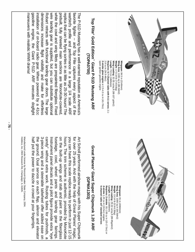
- 75-
Top
Flite
®G
old
Ed
ition
™G
iant P
-51D M
ustan
g A
RF
(TOPA
0700)
The P
-51D M
ustang has a well-earned reputation as A
merica's
favorite fighter -- and Top Flite captures every aspect of the
warbird's profile and perform
ance in a large 1/4 scale AR
Freplica that can be flying sorties in as little as 25-30 hours! T
heprebuilt, fully sheeted m
ain sections are MonoK
ote-covered,w
hile the cowl and w
ing fillets are prepainted fiberglass.Fixed
wire landing gear is supplied, but you can substitute optional
Robart retracts w
ith functional landing gear doors.T
he largedim
ensions increase
flight visibility
and m
ake for
effortlessinstallation of on-board radio gear.
When pow
ered by a 41ccgasoline
engine, the
Giant
P-51D
A
RF
executes
dogfightm
aneuvers with realistic W
WII dram
a!
Great P
lanes
®G
iant S
up
er Ch
ipm
un
k 1.20 AR
F(G
PM
A1303)
Art S
choll performed airshow
magic w
ith his Super C
hipmunk
for over 25 years.And w
ith the help of Great P
lanes' magic,
you can have this scale replica ready to perform in just 12-15
hours.The trim
scheme is authentic, provided by M
onoKote
on the built-up wings and stab and paint on the fiberglass
fuselage, cow
l, w
heel pants
and landing
gear fairings.
Instrument panel decals and a pilot figure provide extra "eye
candy" without extra w
ork.R
outing tubes for pushrods, a 3-piece w
ing and a steerable tailwheel offer added ease on
the ground.D
ual servos on each flap, aileron and elevatorhalf put the pow
er to dazzle a crowd at your fingertips.
Manufactured under license by P
ennzoil-Quaker S
tate Com
pany, 2004.H
obbico, Inc.2904 Research R
d, Cham
paign, IL 61826.
Win
gsp
an:84.5 in (2140m
m)
Win
g A
rea:1245 sq in (80.3dm2)
Weig
ht:17.5-19 lb (7.9-8.6kg)
Win
g L
oad
ing
:32-35 oz/sq ft (98-107 g/dm2)
Len
gth
:73.5 in (1865mm
)R
equ
ires:5-7 C
han
nel rad
io w
ith 9-11 servo
s;2.1-2.8 cu in (34.5-46cc) 2-stro
ke glo
w en
gin
eor 2.5-4.3 cu in (41-70cc)
spark ignition gasoline engine
Win
gsp
an:81 in (2060m
m)
Win
g A
rea:1000 sq in (64.5dm2)
Weig
ht:13-14 lb (5.9-6.35kg)
Win
g L
oad
ing
:29-32 oz/sq ft (89-95g/dm2)
Len
gth
:62.5 in (1590mm
) R
equ
ires:2-stro
ke.91-1.08 cu in (15-17.5cc) or
4-stroke
1.20 cu in (19.5cc) engine, 5-ch
ann
el radio
w/7 stan
dard
servos
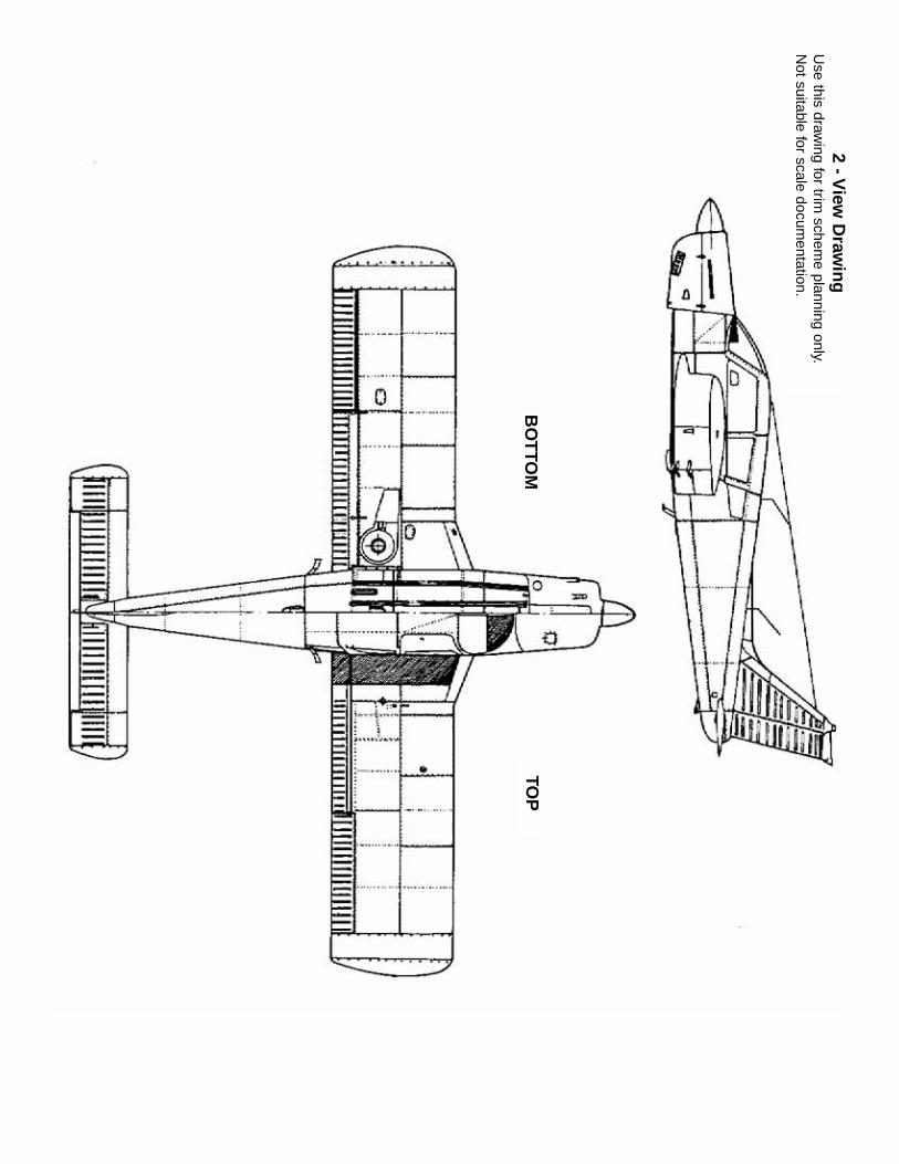
2 - View
Draw
ing
Use this draw
ing for trim schem
e planning only.N
ot suitable for scale documentation.
BO
TTO
MTO
P