Embed Size (px)
Citation preview
Towards a Cloud-Native Radio Access Network
Navid Nikaein, Eryk Schiller, Romain Favraud, Raymond Knopp, Islam Alyafawiand Torsten Braun
Abstract Commoditization and virtualization of wireless networks are changing theeconomics of mobile networks to help network providers, e.g. Mobile Network Op-erator (MNO), Mobile Virtual Network Operator (MVNO), move from proprietaryand bespoke hardware and software platforms towards an open, cost-effective, andflexible cellular ecosystem. In addition, rich and innovative local services can beefficiently materialized through cloudification by leveraging the existing infrastruc-ture. In this work, we present a Radio Access Network as a Service (RANaaS), inwhich a Cloudified Centralized Radio Access Network (C-RAN) is delivered as aservice. RANaaS describes the service life-cycle of an on-demand, elastic, and payas you go RAN instantiated on top of the cloud infrastructure. Due to short deadlinesin many examples of RAN, the fluctuations of processing time, introduced by thevirtualization framework, have a deep impact on the C-RAN performance. While intypical cloud environments, the deadlines of processing time cannot be guaranteed,the cloudification of C-RAN, in which signal processing runs on general purposeprocessors inside Virtual Machines (VMs), is a challenging subject. We describe anexample of real-time cloudifed LTE network deployment using the OpenAirInter-face (OAI) LTE implementation and OpenStack running on commodity hardware.We also show the flexibility and performance of the platform developed. Finally,we draw general conclusions on the RANaaS provisioning problem in future 5Gnetworks.
Eryk Schiller, Islam Alyafawi, Torsten BraunUniversity of Bern, Switzerland, e-mail: {name}@inf.unibe.ch
Navid Nikaein, Romain Favraud, Raymond KnoppEURECOM, France, e-mail: {name.surname}@eurecom.fr
Romain Favraud is also with DCNS Group, France.
1
2 Nikaein, Schiller, et al.
1 Introduction
Every day, we encounter an increasing demand for wireless data use due to a grow-ing number of broadband-capable devices, such as 3G and 4G mobile telephones.To satisfy a higher demand for data rates, service providers and mobile operatorsexpect upgrades and expansion of the existing network, but the required Capital Ex-penditure (CAPEX) and Operational Expenditure (OPEX) are superior to the rev-enue growth [9]. The high upgrade and maintenance costs are mainly caused bythe current architecture of mobile broadband networks, in which the Radio AccessNetwork (RAN) is built upon the integrated Base Transceiver Station (BTS) archi-tecture. Since mobile broadband providers operate on a large scale, the installationand maintenance of a large number of expensive BTSs over vast geographical areasincrease the cost dramatically. Moreover, the new trend of smaller cells will moreseverely affect both the cost and maintenance problem in the future.
A cost-effective RAN solution, which meets the ever-increasing amounts ofmobile data traffic, has to fulfill a set of requirements. First, the new RANhas to quickly and automatically scale with the variable amount of mobiletraffic. Second, it has to consume less power providing higher capacity andnetwork coverage at the same time. Finally, it should allow mobile operatorsto frequently upgrade and operate the service over multiple/heterogeneous air-interfaces.
Only about 15–20% of BTSs operating in the current RAN architecture areloaded more than 50% (with respect to the maximum capacity), which makes thecurrent RAN architecture energy inefficient [8]. An emerging solution to reduce up-grading costs and power consumption is the Centralized-RAN (C-RAN) [13, 17]with resource sharing and exploitation of load patterns at a given geographical area.The C-RAN solution is more adaptable to variations in user data traffic and unpre-dictable mobility patterns than the current RAN. Moreover, it allows coordinatedand joint signal processing to increase the spectral efficiency. Finally, the C-RANrepresents a good match between the spatial-temporal traffic variations and availablecomputational resources and hence power consumption.
Since C-RAN signal processing is centralized, it allows us to apply moresophisticated joint spatio-temporal processing of radio signals, which can increasethe overall spectral efficiency. The joint signal processing approach is consideredby European projects such as Sail [24], iJoin [14], and Mobile Cloud Networking(MCN) [15]. This work has been carried out as part of the MCN vision towardsshifting radio communication networks to the cloud computing paradigm. Cloudcomputing technologies based on virtualization allow us to lower the operationalcosts even more by running the RAN through a) adoption of general purpose ITplatforms instead of expensive specific hardware, b) load balancing, and c) fastdeployment and resource provisioning. Running the RAN in the cloud environmentis not new. The benefit of such an approach has demonstrated 71% of power savings
Towards a Cloud-Native Radio Access Network 3
when compared to the existing system [7]. However, this approach comes at thecost of higher software complexity.
Recent works [27] have shown the feasibility of LTE RAN functions of soft-ware implementation over General Purpose Processors (GPPs), rather than thetraditional implementation over Application-Specific Integrated Circuits (ASICs),Digital Signal Processors (DSPs), or Field-Programmable Gate Arrays (FPGAs).Different software implementations of the LTE base station, which is referred toas evolved Node B (eNB), already exist: a) Amarisoft LTE solution, which is apure-software featuring a fully-functional LTE eNB [2], b) Intel solutions featuringenergy efficiency and high computing performance using a hybrid GPP-acceleratorarchitecture and load-balance algorithms among a flexible IT platform [25] andc) OpenAirInterface (OAI) developed by EURECOM, which is an open-sourceSoftware Defined Radio (SDR) implementation of both the LTE RAN and theEvolved Packet Core (EPC) [12].
This chapter describes recent progress in the C-RAN cloudification (runningsoftware-based RAN in the cloud environment) based on the open source imple-mentations and has the following organization. In Sect. 2, we introduce the concept,architecture, and benefits of centralized RAN in the LTE Network setup. Section 3presents the critical issues of cloudified RAN focusing on fronthaul latencies, pro-cessing delays, and appropriate timing. Our performance evaluation of GPP-basedRAN is provided in Sect. 4 and Base-Band Unit (BBU) processing time is mod-eled in Sect. 5. Possible architectures of cloudified RAN are described in Sect. 6.The description of the cloud datacenter supporting C-RAN resides in Sect. 7. Sec-tion 8 illustrates an example RANaaS with its life-cycle management. Finally, weconclude in Sect. 9.
2 Centralized RAN in the LTE Network
C-RAN based networks are characterized by the decomposition of a BTS into twoentities namely Base-Band Unit (BBU) and Remote Radio Head (RRH). In C-RAN,the RRH stays at the location of the BTS, while the BBU gets relocated into a cen-tral processing pool, which hosts a significant number of distinct BBUs [27]. Inorder to allow for signal processing at a remote BBU, a point-to-point high capacityinterface of short delay is required to transport I/Q samples (i.e., digitized analogradio signals) between RRH and BBU. There are a few examples of link standardsmeeting the required connectivity expectations such as Open Radio Interface (ORI),Open Base Station Architecture Initiative (OBSAI), or Common Public Radio Inter-face (CPRI). Even though many recent works have shown the feasibility of C-RANimplementation and the C-RAN importance for the MNOs, there are still three openquestions that has to be thoroughly investigated upon a C-RAN system design.
4 Nikaein, Schiller, et al.
1. Dimensioning of the fronthaul capacity: a BBU pool has to support ahigh fronthaul capacity to transport I/Q samples for a typical set of 10–1000 base-stations working in the BBU–RRH configuration. Due to a lowprocessing budget of RAN, the upper bound for the maximum one-waydelay has to be estimated. Moreover, a very low jitter has to be maintainedfor the clock synchronization among BBUs and RRHs.
2. Processing budget at the BBU: in the LTE FDD setup, the Hybrid auto-matic repeat request (HARQ) mechanism with an 8 ms acknowledgmentresponse time provides an upper bound for the total delay of both fronthaullatency and BBU processing time.
3. The real-time requirements of the Operating-System andVirtualization-System: to successfully provide frame/subframe tim-ings, the execution environment of the BBU has to support strict deadlinesof the code execution. Moreover, load variations in the cell (e.g.,day/night load shifts) impose the requirement on the on-demand resourceprovisioning and load balancing of the BBU pool.
There are also many other challenges in this field [6], such as front-haul mul-tiplexing, optimal clustering of BBUs and RRHs, BBU interconnection, coopera-tive radio resource management, energy optimization, and channel estimation tech-niques. The following subsections focus on the critical issues, and present C-RANfeasible architectures.
3 Critical Issues of C-RAN
In the following subsections, we evaluate the most important critical issues of theC-RAN. We concentrate on the fronthaul capacity problem, BBU signal processing,and real-time cloud infrastructure for signal processing [18].
3.1 Fronthaul Capacity
We start with the description of fronthaul requirements. A very fast link of low delayis necessary as the BBU processes the computationally most heavy physical (PHY)layer of the LTE standards. Many factors contribute to the data rate of the fronthaul,which depends on the cell and fronthaul configurations. Eq. 1 calculates the requireddata rate based on such configurations:
Towards a Cloud-Native Radio Access Network 5
C f ronthaul = 2×N ×M×F ×W ×C︸ ︷︷ ︸cell configuration
× O×K︸ ︷︷ ︸fronthaul configuration
, (1)
where N is the number of receiving/transmitting (Tx/Rx) antenna ports, M is thenumber of sectors, F represents the sampling rate, W is the bit width of an I/Qsymbol, C number of carrier components, O is the ratio of transport protocol andcoding overheads, and K is the compression factor. The following table shows therequired fronthaul capacity for a simple set of configurations. An overall overheadis assumed to be 1.33, which is the result of the the protocol overhead ratio of 16/15and the line coding of 10/8 (CPRI case). One can observe that the fronthaul capac-ity heavily depends on the cell configuration and rapidly grows with the increasedsampling rate, number of antennas/sectors and carrier components.
Table 1 Fronthaul capacity for different configurations
BW (MHz) N M F W (bits) O C K C f ronthaul (Mb/s)
1.4 1×1 1 1.92 16 1.33 1 1 815 1×1 1 7.68 16 1.33 1 1 3265 2×2 1 7.68 16 1.33 1 1 65310 4×4 1 15.36 16 1.33 1 1/2 130020 1×1 1 30.72 16 1.33 1 1 130020 2×2 3 30.72 16 1.33 1 1 785020 4×4 3 30.72 16 1.33 1 1 15600
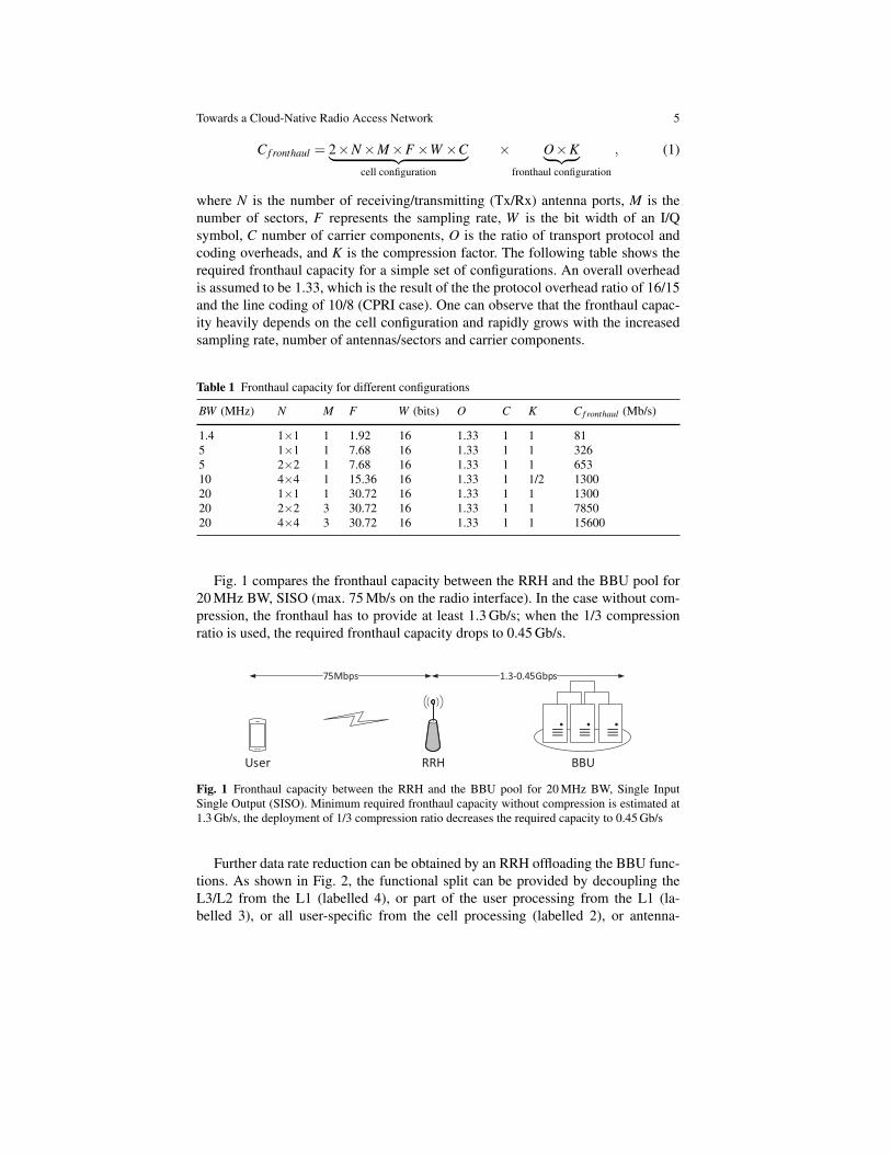
Fig. 1 compares the fronthaul capacity between the RRH and the BBU pool for20 MHz BW, SISO (max. 75 Mb/s on the radio interface). In the case without com-pression, the fronthaul has to provide at least 1.3 Gb/s; when the 1/3 compressionratio is used, the required fronthaul capacity drops to 0.45 Gb/s.
BBURRHUser
75Mbps 1.3-0.45Gbps
Fig. 1 Fronthaul capacity between the RRH and the BBU pool for 20 MHz BW, Single InputSingle Output (SISO). Minimum required fronthaul capacity without compression is estimated at1.3 Gb/s, the deployment of 1/3 compression ratio decreases the required capacity to 0.45 Gb/s
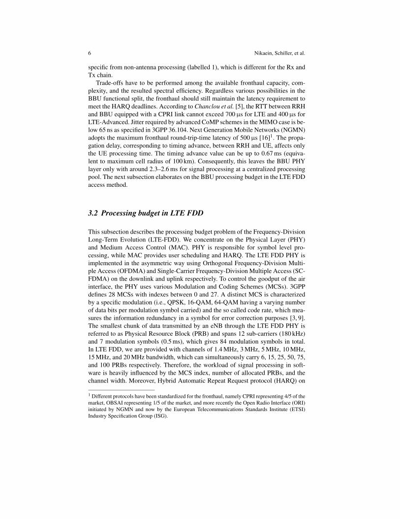
Further data rate reduction can be obtained by an RRH offloading the BBU func-tions. As shown in Fig. 2, the functional split can be provided by decoupling theL3/L2 from the L1 (labelled 4), or part of the user processing from the L1 (la-belled 3), or all user-specific from the cell processing (labelled 2), or antenna-
6 Nikaein, Schiller, et al.
specific from non-antenna processing (labelled 1), which is different for the Rx andTx chain.
Trade-offs have to be performed among the available fronthaul capacity, com-plexity, and the resulted spectral efficiency. Regardless various possibilities in theBBU functional split, the fronthaul should still maintain the latency requirement tomeet the HARQ deadlines. According to Chanclou et al. [5], the RTT between RRHand BBU equipped with a CPRI link cannot exceed 700µs for LTE and 400µs forLTE-Advanced. Jitter required by advanced CoMP schemes in the MIMO case is be-low 65 ns as specified in 3GPP 36.104. Next Generation Mobile Networks (NGMN)adopts the maximum fronthaul round-trip-time latency of 500µs [16]1. The propa-gation delay, corresponding to timing advance, between RRH and UE, affects onlythe UE processing time. The timing advance value can be up to 0.67 ms (equiva-lent to maximum cell radius of 100 km). Consequently, this leaves the BBU PHYlayer only with around 2.3–2.6 ms for signal processing at a centralized processingpool. The next subsection elaborates on the BBU processing budget in the LTE FDDaccess method.
3.2 Processing budget in LTE FDD
This subsection describes the processing budget problem of the Frequency-DivisionLong-Term Evolution (LTE-FDD). We concentrate on the Physical Layer (PHY)and Medium Access Control (MAC). PHY is responsible for symbol level pro-cessing, while MAC provides user scheduling and HARQ. The LTE FDD PHY isimplemented in the asymmetric way using Orthogonal Frequency-Division Multi-ple Access (OFDMA) and Single-Carrier Frequency-Division Multiple Access (SC-FDMA) on the downlink and uplink respectively. To control the goodput of the airinterface, the PHY uses various Modulation and Coding Schemes (MCSs). 3GPPdefines 28 MCSs with indexes between 0 and 27. A distinct MCS is characterizedby a specific modulation (i.e., QPSK, 16-QAM, 64-QAM having a varying numberof data bits per modulation symbol carried) and the so called code rate, which mea-sures the information redundancy in a symbol for error correction purposes [3, 9].The smallest chunk of data transmitted by an eNB through the LTE FDD PHY isreferred to as Physical Resource Block (PRB) and spans 12 sub-carriers (180 kHz)and 7 modulation symbols (0.5 ms), which gives 84 modulation symbols in total.In LTE FDD, we are provided with channels of 1.4 MHz, 3 MHz, 5 MHz, 10 MHz,15 MHz, and 20 MHz bandwidth, which can simultaneously carry 6, 15, 25, 50, 75,and 100 PRBs respectively. Therefore, the workload of signal processing in soft-ware is heavily influenced by the MCS index, number of allocated PRBs, and thechannel width. Moreover, Hybrid Automatic Repeat Request protocol (HARQ) on
1 Different protocols have been standardized for the fronthaul, namely CPRI representing 4/5 of themarket, OBSAI representing 1/5 of the market, and more recently the Open Radio Interface (ORI)initiated by NGMN and now by the European Telecommunications Standards Institute (ETSI)Industry Specification Group (ISG).
Towards a Cloud-Native Radio Access Network 7
the MAC layer introduces short deadline for signal processing on the PHY. Due toHARQ, every transmitted chunk of information has to be acknowledged back at thetransmitter to allow for retransmissions. In LTE-FDD, the retransmission time isequal to THARQ of 8 ms. Let us briefly explain the retransmission mechanism. EveryLTE FDD subframe (subframe is later referred to as SF) lasts for 1 ms and con-tains information chunks carried within PRBs. The HARQ protocol states that theAcknowledgment (ACK) or Negative Acknowledgment (NACK) for a data chunkreceived at subframe N has to be issued upon a subframe N+4 and decoded at thetransmitter before subframe N+8, which either sends new data or again negativelyacknowledged chunks. In the following subsection, we briefly summarize the BBUfunctions.
3.3 BBU Functions
Fig. 2 illustrates the main RAN functions in both TX and RX spanning all the lay-ers, which has to be evaluated to characterize the BBU processing time and assessthe feasibility of a full GPP RAN. Since the main processing bottleneck resides inthe physical layer, the scope of the analysis in this chapter is limited to the BBUfunctions. From the figure, it can be observed that the overall processing is the sumof cell- and user-specific processing. The former only depends on the channel band-width and thus imposes a constant base processing load on the system, whereas thelatter depends on the MCS and resource blocks allocated to users as well as theSignal-to-Noise Ratio (SNR) and channel conditions. The figure also shows the in-terfaces where the functional split could happen to offload the processing either toan accelerator or to an RRH.
To RF
To RRH
P/SIFFT
CPin
Subcarrier
mapping
To RF
To RRH
S/PCPout
FFT
Subcarrier
demapping
Cell processing
DL OFDMA (TX)
UL SC-FDMA (RX)
ModulationCodingRRC/PDCP/
RLC/MAC
S1
termination
Demodulati
onDecoding
RRC/PDCP/
RLC/MAC
S1
termination
User processingTime-domainFreq.-domain
L1 (baseband)L2/L3
eICIC
CoMP
CIPRI
OBSAI
ORI
CIPRI
OBSAI
ORI
124 3
Fig. 2 Functional block diagram of downlink and uplink for LTE eNB
To meet the timing and protocol requirements, the BBU must finish processingbefore the deadline previously discussed at the beginning of Sect. 3.2. Each MAC
8 Nikaein, Schiller, et al.
N N+1 N+2 N+3 N+4 N+5 N+6 N+7 N+8 N+9 N+10
TX processing
for SF N
N N+1 N+2 N+3 N+4 N+5 N+6 N+7 N+8 N+9 N+10
eNB
UE
N-1
RX processing
for SF N
TX processing
for SF N+4
RX processing
for SF N+4
Transport +
Propagation
delay
TX processing
for SF N+8
Downlink
N-1
Propagation +
acquisition +
transport delay
Acquisition
delay
offset ACK / NACK
UE Processing eNB Processing
(a) Downlink HARQ timing.
N N+1 N+2 N+3 N+4 N+5 N+6 N+7 N+8 N+9 N+10
TX processing
for SF N
N N+1 N+2 N+3 N+4 N+5 N+6 N+7 N+8 N+9 N+10
eNB
UE
N-1
RX
processing
for SF N
TX processing +
transport delay
for SF N+4
RX processing
for SF N+4 TX processing
for SF N+8
Uplink
N-1
Propagation +
acquisition +
transport delay
ACK / NACKoffset
Propagation
delay
Acquisition
delay
Propagation +
acquisition +
transport delay
eNB Processing UE Processing
(b) Uplink HARQ timing.
BBURRHRTT/Km
CPRI Interfaces
TProp
TAcq = 1 ms
3 ms
TProp
TAcq = 1 ms
TRX
TTX
TRX
TTX
TRX
TTX
TTrans
TTrans
UEmax processing = 3 ms
T
TProp
UE
O set
THARQ = 8 ms
(c) HARQ process timing requirement.
Fig. 3 FDD LTE timing
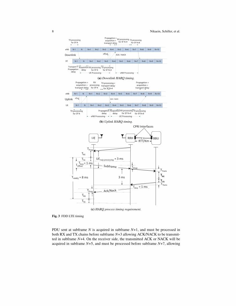
PDU sent at subframe N is acquired in subframe N+1, and must be processed inboth RX and TX chains before subframe N+3 allowing ACK/NACK to be transmit-ted in subframe N+4. On the receiver side, the transmitted ACK or NACK will beacquired in subframe N+5, and must be processed before subframe N+7, allowing
Towards a Cloud-Native Radio Access Network 9
the transmitter to retransmit or clear the MAC PDU sent in subframe N. Fig. 3(a)and 3(b) show an example of timing deadlines required to process each subframe onthe downlink and uplink respectively. Fig. 3(c) graphically represents the communi-cation between the UE, RRH, and BBU. It can be observed that the total processingtime is 3 ms. The available processing time for a BBU to perform the reception andtransmission is upper-bounded by HARQ round trip time (THARQ), propagation time(TProp.), acquisition time (TAcq.), and fronthaul transport time (TTrans.) as follows:
Trx +Ttx ≤ THARQ/2− (TProp.+TAcq.+TTrans.+TO f f set) , (2)
where THARQ = 8 ms, TProp. is compensated by the timing advance of the UE:TProp. = 0, TAcq. is equal to the duration of the subframe: TAcq. = 1 ms, and thereis no BBU offset on the downlink: TO f f set = 0. Depending on the implementation,the maximum tolerated transport latency depends on the BBU processing time andHARQ period. The LTE FDD access method puts a particular focus on perfect tim-ing of (sub-) frame processing. To accomplish this goal, the processing system hasto fulfill real-time requirements. The next subsection focuses on the real-time cloudsystem design capable of C-RAN provisioning.
3.4 Real-time Operating System and Virtualization Environment
A typical general purpose operating systems (GPOS) is not designed to supportreal-time applications with hard deadline. Hard real-time applications have stricttiming requirements to meet deadlines. Otherwise unexpected behaviors can occurcompromising performance. For instance, Linux is not a hard real-time operatingsystem as the kernel can suspend any task when a desired runtime has expired. Asa result, the task can remain suspended for an arbitrarily long period of time. Thekernel uses a scheduling policy that decides on the allocation of processing time totasks. A scheduler that always guarantees the worst case performance (or better ifpossible) and also provides a deterministic behavior (with short interrupt-responsedelay of 100µs) for the real-time applications is required. Recently, a new sched-uler, named SCHED DEADLINE, is introduced in the Linux mainstream kernelthat allows each application to set a triple of (runtime[ns],deadline[ns], period[ns]),where runtime ≤ deadline ≤ period.2 The scheduler is able to preempts the kernelcode to meet the deadline and allocates the required runtime (i.e., CPU time) to eachtask period.
A good deadline scheduler can simplify C-RAN deployment, because Software-based Radio providing RAN in software is a real-time application that requires harddeadlines to maintain frame and subframe timing. In the C-RAN setting, the soft-ware radio application runs on a virtualized environment, where the hardware is ei-ther fully, partially, or not virtualized. Two main approaches exist to virtualization:
2 http://www.kernel.org/doc/Documentation/scheduler/sched-deadline.txt
10 Nikaein, Schiller, et al.
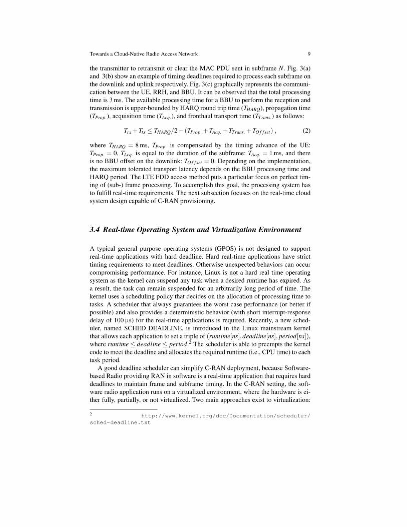
virtual machines (e.g., Linux KVM3 and Xen4) or containers (e.g., LinuX ContainerLXC5 and Docker6) as shown in Fig. 4. In a virtual machine (VM), a complete op-erating system (guest OS) is used with the associated overhead due to emulatingvirtual hardware, whereas containers use and share the OS and device drivers of thehost. While VMs rely on the hypervisor to requests for CPU, memory, hard disk,network and other hardware resources, containers exploit the OS-level capabilities.Similar to VMs, containers preserve the advantage of virtualization in terms of flex-ibility (containerize a system or an application), resource provisioning, decoupling,management and scaling. Thus, containers are lightweight as they do not emulatea hardware layer (share the same kernel and thus application is native with respectto the host) and therefore have a smaller footprint than VMs, start up much faster,and offer near bare metal runtime performance. This comes at the expense of lessisolation and greater dependency on the host kernel.
GLIBC / FS / Libs /
Bins
Applications
Hardware
Hypervisor (Type 1)
Applications
Virtual MachineContainer
Kernel
Host OS
GLIBC / FS / Libs / BinsVirtual Hardware
Kernel
Guest OS
GLIBC / FS / Libs /
Bins
Applications
Virtual Hardware
Kernel
Guest OS
GLIBC / FS / Libs /
Bins
Applications
Hardware
Kernel
Host OS
GLIBC / FS / Libs / Bins
Container Engine (lxc, libvirt)
Type 1 Type 2Type 1 Type 2
Fig. 4 Comparison of a virtual machine and container virtualized environment
Two other important aspects when targeting RAN virtualization are:
• I/O Virtualization: I/O access is a key for a fast access to the fronthaul interfaceand to the hardware accelerators that might be shared among BBUs. In hyper-visor approach to virtualization (i.e., VM), IO virtualization is done through thehardware emulation layer under the control of hypervisor, where as in a containerthis is materialized through device mapping. Thus, direct access to hardware iseasier in containers than in VMs as they operate at the host OS level. In a VM,additional techniques might be needed (e.g., para-virtualization or CPU-assisted
3 http://www.linux-kvm.org4 http://www.xenserver.org5 http://linuxcontainers.org6 http://www.docker.com
Towards a Cloud-Native Radio Access Network 11
virtualization) to provide a direct or fast access to the hardware. When it comesto sharing I/O resources among multiple physical/virtual servers, and in particu-lar that of radio front-end hardware, new techniques such as single/multi root I/Ovirtualization (SR/MR-IOV) are required.
• Service composition of the software radio application: A radio applicationcan be defined as a composition of three types of service [15], atomic servicethat executes a single business or technical function and is not subject to furtherdecomposition, composed service that aggregates and combines atomic servicestogether with orchestration logic, and support service that provides specific (oftencommon) functions available to all types of service. An atomic service in RANcan be defined on per carrier, per layer, per function basis. For instance, a radioapplication could be defined as a composition of layer 1 and layer 2/3 servicessupported by a monitoring as a service.
4 OpenAirInterface based Evaluation of the Cloud ExecutionEnvironment
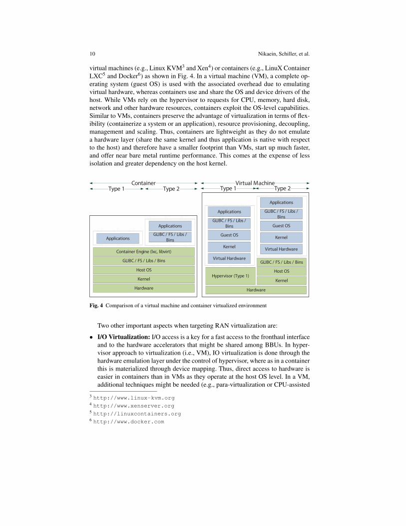
Sect. 1 gives a brief insight into various software-based implementations of BBU.This section, provides an overview of the OpenAirInterface (OAI), which is a keysoftware component in our studies. The main advantage of OAI is that it an open-source project that implements the LTE 3GPP Release-10 standard. It includes afully functional wireless stack with PHY, MAC, Radio Link Control (RLC), PacketData Convergence Protocol (PDCP) and Radio Resource Control (RRC) layersas well as Non-Access-Stratum (NAS) drivers for IPv4/IPv6 interconnection withother network services [20]. Regarding the LTE FDD, OAI provides both the uplinkand downlink processing chains with SC-FDMA and OFDMA respectively (c.f.,Sect. 3.2). For efficient numerical computing on the PHY, OAI uses specially opti-mized SIMD Intel instruction sets (i.e., MMX/SSE3/SSE4). Fig. 5 presents the OAImulti-threaded signal processing at the subframe level. As an example, the mobileair-interface of a client terminal started transmitting subframe N-1 at time (a). Thedecoder thread of the OAI lte-softmodem starts processing the subframe N-1 at (1)after the subframe is entirely received at time instance (b). Due to the fact that the
Fig. 5 Processing orders in OAI
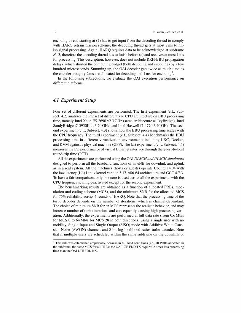
12 Nikaein, Schiller, et al.
encoding thread starting at (2) has to get input from the decoding thread to complywith HARQ retransmission scheme, the decoding thread gets at most 2 ms to fin-ish signal processing. Again, HARQ requires data to be acknowledged at subframeN+3, therefore the encoding thread has to finish before (c) and receives at most 1 msfor processing. This description, however, does not include RRH-BBU propagationdelays, which shorten the computing budget (both decoding and encoding) by a fewhundred microseconds. Summing up, the OAI decoder gets twice as much time asthe encoder; roughly 2 ms are allocated for decoding and 1 ms for encoding7.
In the following subsections, we evaluate the OAI execution performance ondifferent platforms.
4.1 Experiment Setup
Four set of different experiments are performed. The first experiment (c.f., Sub-sect. 4.2) analyses the impact of different x86 CPU architecture on BBU processingtime, namely Intel Xeon E5-2690 v2 3 GHz (same architecture as IvyBridge), IntelSandyBridge i7-3930K at 3.20 GHz, and Intel Haswell i7-4770 3.40 GHz. The sec-ond experiment (c.f., Subsect. 4.3) shows how the BBU processing time scales withthe CPU frequency. The third experiment (c.f., Subsect. 4.4) benchmarks the BBUprocessing time in different virtualization environments including LXC, Docker,and KVM against a physical machine (GPP). The last experiment (c.f., Subsect. 4.5)measures the I/O performance of virtual Ethernet interface through the guest-to-hostround-trip time (RTT).
All the experiments are performed using the OAI DLSCH and ULSCH simulatorsdesigned to perform all the baseband functions of an eNB for downlink and uplinkas in a real system. All the machines (hosts or guests) operate Ubuntu 14.04 withthe low latency (LL) Linux kernel version 3.17, x86-64 architecture and GCC 4.7.3.To have a fair comparison, only one core is used across all the experiments with theCPU frequency scaling deactivated except for the second experiment.
The benchmarking results are obtained as a function of allocated PRBs, mod-ulation and coding scheme (MCS), and the minimum SNR for the allocated MCSfor 75% reliability across 4 rounds of HARQ. Note that the processing time of theturbo decoder depends on the number of iterations, which is channel-dependant.The choice of minimum SNR for an MCS represents the realistic behavior, and mayincrease number of turbo iterations and consequently causing high processing vari-ation. Additionally, the experiments are performed at full data rate (from 0.6 Mb/sfor MCS 0 to 64 Mb/s for MCS 28 in both directions) using a single user with nomobility, Single-Input and Single-Output (SISO) mode with Additive White Gaus-sian Noise (AWGN) channel, and 8-bit log-likelihood ratios turbo decoder. Notethat if multiple users are scheduled within the same subframe on the downlink or
7 This rule was established empirically, because in full load conditions (i.e., all PRBs allocated inthe subframe; the same MCS for all PRBs) the OAI LTE FDD TX requires 2 times less processingtime than the OAI LTE FDD RX.
Towards a Cloud-Native Radio Access Network 13
uplink, the total processing depends on the allocated PRB and MCS, which is lowerthan a single user case with all PRBs and highest MCS. Thus, the single user caserepresents the worst case scenario.
The processing time of each signal processing module is calculated using times-tamps at the beginning and at the end of each BBU function. OAI uses the rdtscinstruction implemented on all x86 and x64 processors to get very precise times-tamps, which counts the number of CPU tics since the reset. Therefore the process-ing time is measured as a number of CPU tics between the beginning and end of aparticular processing function divided by the CPU frequency8.
To allow for a rigorous analysis, the total and per function BBU processing timeare measured. For statistical analysis, a large number of processing time samples(10000) are collected for each BBU function to calculate the average, median, firstquantile, third quantile, minimum and maximum processing time for all the sub-frames on the uplink and downlink.
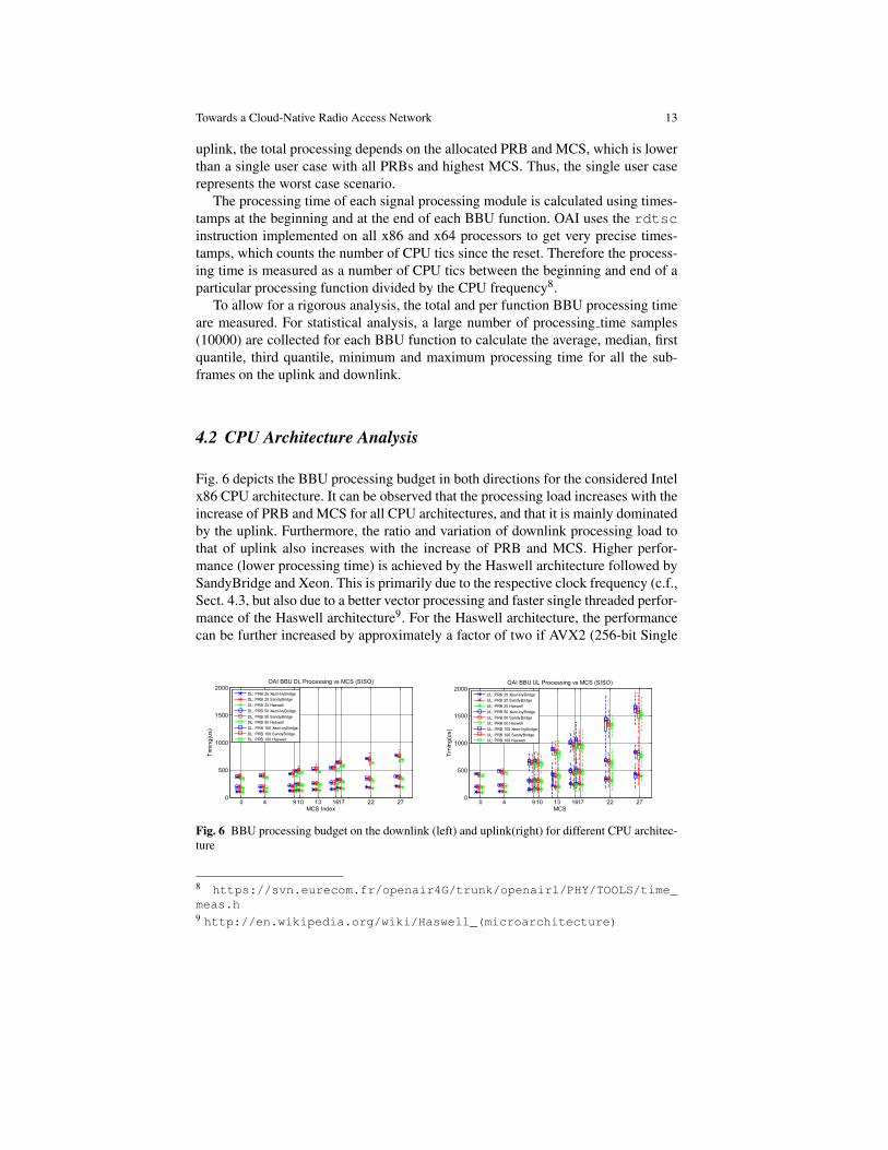
4.2 CPU Architecture Analysis
Fig. 6 depicts the BBU processing budget in both directions for the considered Intelx86 CPU architecture. It can be observed that the processing load increases with theincrease of PRB and MCS for all CPU architectures, and that it is mainly dominatedby the uplink. Furthermore, the ratio and variation of downlink processing load tothat of uplink also increases with the increase of PRB and MCS. Higher perfor-mance (lower processing time) is achieved by the Haswell architecture followed bySandyBridge and Xeon. This is primarily due to the respective clock frequency (c.f.,Sect. 4.3, but also due to a better vector processing and faster single threaded perfor-mance of the Haswell architecture9. For the Haswell architecture, the performancecan be further increased by approximately a factor of two if AVX2 (256-bit Single
0 4 910 13 1617 22 270
500
1000
1500
2000
MCS Index
Tim
ing
(us)
OAI BBU DL Processing vs MCS (SISO)
DL: PRB 25 Xeon-IvyBridge
DL: PRB 25 SandyBridge
DL: PRB 25 Haswell
DL: PRB 50 Xeon-IvyBridge
DL: PRB 50 SandyBridge
DL: PRB 50 Haswell
DL: PRB 100 Xeon-IvyBridge
DL: PRB 100 SandyBridge
DL: PRB 100 Haswell
0 4 910 13 1617 22 270
500
1000
1500
2000
MCS
Tim
ing
(us)
OAI BBU UL Processing vs MCS (SISO)
UL: PRB 25 Xeon-IvyBridge
UL: PRB 25 SandyBridge
UL: PRB 25 Haswell
UL: PRB 50 Xeon-IvyBridge
UL: PRB 50 SandyBridge
UL: PRB 50 Haswell
UL: PRB 100 Xeon-IvyBridge
UL: PRB 100 SandyBridge
UL: PRB 100 Haswell
Fig. 6 BBU processing budget on the downlink (left) and uplink(right) for different CPU architec-ture
8 https://svn.eurecom.fr/openair4G/trunk/openair1/PHY/TOOLS/time_meas.h9 http://en.wikipedia.org/wiki/Haswell_(microarchitecture)
14 Nikaein, Schiller, et al.
instruction multiple data (SIMD) compared to 128-bit SIMD) instructions are usedto optimize the turbo decoding and FFT processing.
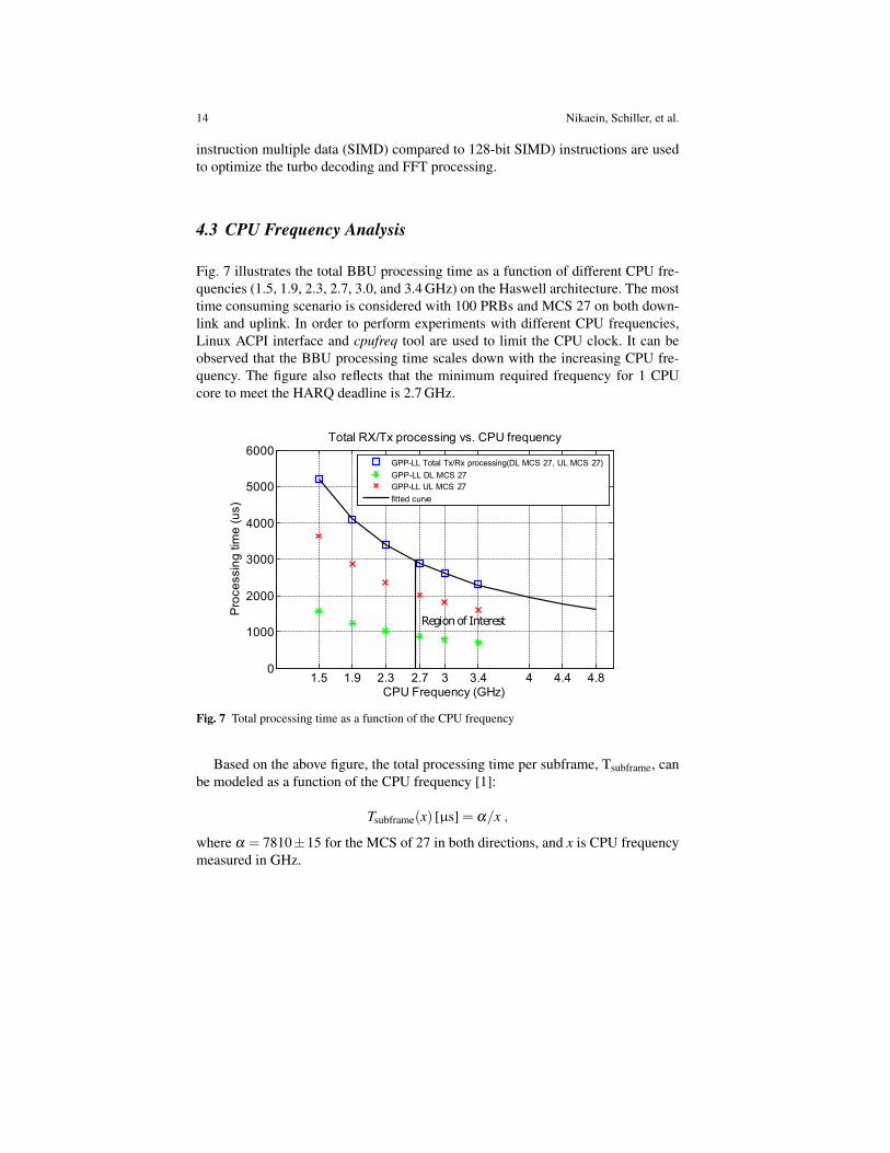
4.3 CPU Frequency Analysis
Fig. 7 illustrates the total BBU processing time as a function of different CPU fre-quencies (1.5, 1.9, 2.3, 2.7, 3.0, and 3.4 GHz) on the Haswell architecture. The mosttime consuming scenario is considered with 100 PRBs and MCS 27 on both down-link and uplink. In order to perform experiments with different CPU frequencies,Linux ACPI interface and cpufreq tool are used to limit the CPU clock. It can beobserved that the BBU processing time scales down with the increasing CPU fre-quency. The figure also reflects that the minimum required frequency for 1 CPUcore to meet the HARQ deadline is 2.7 GHz.
1.5 1.9 2.3 2.7 3 3.4 4 4.4 4.80
1000
2000
3000
4000
5000
6000
CPU Frequency (GHz)
Pro
ce
ssin
g tim
e (
us)
Total RX/Tx processing vs. CPU frequency
GPP-LL Total Tx/Rx processing(DL MCS 27, UL MCS 27)
GPP-LL DL MCS 27
GPP-LL UL MCS 27
fitted curve
Region of Interest
Fig. 7 Total processing time as a function of the CPU frequency
Based on the above figure, the total processing time per subframe, Tsubframe, canbe modeled as a function of the CPU frequency [1]:
Tsubframe(x) [µs] = α/x ,
where α = 7810±15 for the MCS of 27 in both directions, and x is CPU frequencymeasured in GHz.
Towards a Cloud-Native Radio Access Network 15
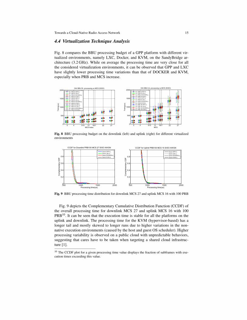
4.4 Virtualization Technique Analysis
Fig. 8 compares the BBU processing budget of a GPP platform with different vir-tualized environments, namely LXC, Docker, and KVM, on the SandyBridge ar-chitecture (3.2 GHz). While on average the processing time are very close for allthe considered virtualization environments, it can be observed that GPP and LXChave slightly lower processing time variations than that of DOCKER and KVM,especially when PRB and MCS increase.
0 4 910 13 1617 22 270
500
1000
1500
2000
MCS Index
Tim
ing
(us)
OAI BBU DL processing vs MCS (SISO)
DL: PRB 25 GPP-LL
DL: PRB 25 LXC-LL
DL: PRB 25 DOCKER-LL
DL: PRB 25 KVM-LL
DL: PRB 50 GPP-LL
DL: PRB 50 LXC-LL
DL: PRB 50 DOCKER-LL
DL: PRB 50 KVM-LL
DL: PRB 100 GPP-LL
DL: PRB 100 LXC-LL
DL: PRB 100 DOCKER-LL
DL: PRB 100 KVM-LL
0 4 910 13 1617 22 270
500
1000
1500
2000
MCS
Tim
ing
(us)
OAI BBU UL processing vs MCS (SISO)
UL: PRB 25 GPP-LL
UL: PRB 25 LXC-LL
UL: PRB 25 DOCKER-LL
UL: PRB 25 KVM-LL
UL: PRB 50 GPP-LL
UL: PRB 50 LXC-LL
UL: PRB 50 DOCKER-LL
UL: PRB 50 KVM-LL
UL: PRB 100 GPP-LL
UL: PRB 100 LXC-LL
UL: PRB 100 DOCKER-LL
UL: PRB 100 KVM-LL
Fig. 8 BBU processing budget on the downlink (left) and uplink (right) for different virtualizedenvironments
500 1000 1500 20000
0.2
0.4
0.6
0.8
1
Processing time(us)
Co
mp
lem
en
tary
CD
F
CCDF for Downlink PRB100 MCS 27 SISO AWGN
Guest GPP-LL
Guest LXC-LL
Guest DOCKER-LL
Guest KVM-LL
500 1000 1500 20000
0.2
0.4
0.6
0.8
1
Processing time(us)
Co
mp
lem
en
tary
CD
F
CCDF for Uplink PRB100 MCS 16 SISO AWGN
Guest GPP-LL
Guest LXC-LL
Guest DOCKER-LL
Guest KVM-LL
Fig. 9 BBU processing time distribution for downlink MCS 27 and uplink MCS 16 with 100 PRB
Fig. 9 depicts the Complementary Cumulative Distribution Function (CCDF) ofthe overall processing time for downlink MCS 27 and uplink MCS 16 with 100PRB10. It can be seen that the execution time is stable for all the platforms on theuplink and downlink. The processing time for the KVM (hypervisor-based) has alonger tail and mostly skewed to longer runs due to higher variations in the non-native execution environments (caused by the host and guest OS scheduler). Higherprocessing variability is observed on a public cloud with unpredictable behaviors,suggesting that cares have to be taken when targeting a shared cloud infrastruc-ture [1].
10 The CCDF plot for a given processing time value displays the fraction of subframes with exe-cution times exceeding this value.
16 Nikaein, Schiller, et al.
4.5 I/O Performance Analysis
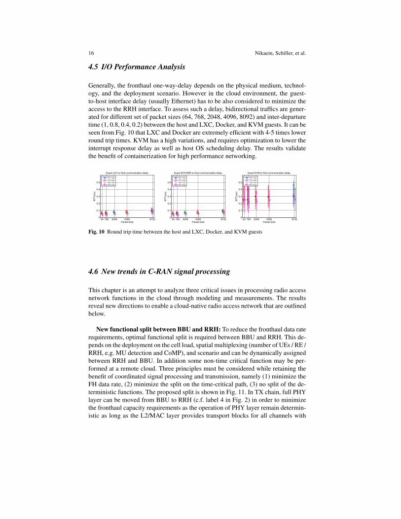
Generally, the fronthaul one-way-delay depends on the physical medium, technol-ogy, and the deployment scenario. However in the cloud environment, the guest-to-host interface delay (usually Ethernet) has to be also considered to minimize theaccess to the RRH interface. To assess such a delay, bidirectional traffics are gener-ated for different set of packet sizes (64, 768, 2048, 4096, 8092) and inter-departuretime (1, 0.8, 0.4, 0.2) between the host and LXC, Docker, and KVM guests. It can beseen from Fig. 10 that LXC and Docker are extremely efficient with 4-5 times lowerround trip times. KVM has a high variations, and requires optimization to lower theinterrupt response delay as well as host OS scheduling delay. The results validatethe benefit of containerization for high performance networking.
64 768 2048 4096 81920
0.1
0.2
0.3
0.4
0.5
Packet Size
RT
T(m
s)
Guest LXC to Host communication delay
IDT 1.0(s)
IDT 0.8(s)
IDT 0.4(s)
IDT 0.2(s)
64 768 2048 4096 81920
0.1
0.2
0.3
0.4
0.5
Packet Size
RT
T(m
s)
Guest DOCKER to Host communication delay
IDT 1.0(s)
IDT 0.8(s)
IDT 0.4(s)
IDT 0.2(s)
64 768 2048 4096 81920
0.1
0.2
0.3
0.4
0.5
Packet Size
RT
T(m
s)
Guest KVM to Host communication delay
IDT 1.0(s)
IDT 0.8(s)
IDT 0.4(s)
IDT 0.2(s)
Fig. 10 Round trip time between the host and LXC, Docker, and KVM guests
4.6 New trends in C-RAN signal processing
This chapter is an attempt to analyze three critical issues in processing radio accessnetwork functions in the cloud through modeling and measurements. The resultsreveal new directions to enable a cloud-native radio access network that are outlinedbelow.
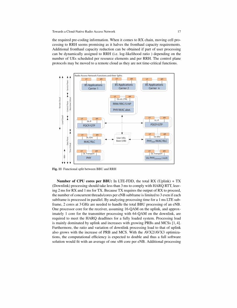
New functional split between BBU and RRH: To reduce the fronthaul data raterequirements, optimal functional split is required between BBU and RRH. This de-pends on the deployment on the cell load, spatial multiplexing (number of UEs / RE /RRH, e.g. MU detection and CoMP), and scenario and can be dynamically assignedbetween RRH and BBU. In addition some non-time critical function may be per-formed at a remote cloud. Three principles must be considered while retaining thebenefit of coordinated signal processing and transmission, namely (1) minimize theFH data rate, (2) minimize the split on the time-critical path, (3) no split of the de-terministic functions. The proposed split is shown in Fig. 11. In TX chain, full PHYlayer can be moved from BBU to RRH (c.f. label 4 in Fig. 2) in order to minimizethe fronthaul capacity requirements as the operation of PHY layer remain determin-istic as long as the L2/MAC layer provides transport blocks for all channels with
Towards a Cloud-Native Radio Access Network 17
the required pre-coding information. When it comes to RX chain, moving cell pro-cessing to RRH seems promising as it halves the fronthaul capacity requirements.Additional fronthaul capacity reduction can be obtained if part of user processingcan be dynamically assigned to RRH (i.e. log-likelihood ratio ) depending on thenumber of UEs scheduled per resource elements and per RRH. The control planeprotocols may be moved to a remote cloud as they are not time-critical functions.
UIB
Radio Access Network Functions and their Splits
BS Applications
Carrier n
BS Applications
Carrier 2BS Applications
Carrier 1
DL+UL CTRL
DL SDU
APII/F
APII/F
RRM/RRC/S1AP
MAC/RLC
DL IP
APII/F
PDCP/GTP
UL SDU
APII/F
PHYUser/MAC/RLC
UL IP
APII/F
PDCP/GTP
User Info.
Base (UIB)
PHY/MAC abst.
DL Transport
APII/F
PHY
DL Transport
APII/F
UL PHYCommon (+LLR)
Tim
e C
riti
c al
No
n-t
ime
Cri
tica
l
Da
ta P
lan
eC
on
tro
l Pla
ne
Serv
ice
Pla
ne
RR
HLo
cal C
lou
d
Re
mo
te C
lou
d
APII/F APII/F APII/F
Fig. 11 Functional split between BBU and RRH
Number of CPU cores per BBU: In LTE-FDD, the total RX (Uplink) + TX(Downlink) processing should take less than 3 ms to comply with HARQ RTT, leav-ing 2 ms for RX and 1 ms for TX. Because TX requires the output of RX to proceed,the number of concurrent threads/cores per eNB subframe is limited to 3 even if eachsubframe is processed in parallel. By analyzing processing time for a 1 ms LTE sub-frame, 2 cores at 3 GHz are needed to handle the total BBU processing of an eNB.One processor core for the receiver, assuming 16-QAM on the uplink, and approx-imately 1 core for the transmitter processing with 64-QAM on the downlink, arerequired to meet the HARQ deadlines for a fully loaded system. Processing loadis mainly dominated by uplink and increases with growing PRBs and MCSs [1, 4].Furthermore, the ratio and variation of downlink processing load to that of uplinkalso grows with the increase of PRB and MCS. With the AVX2/AVX3 optimiza-tions, the computational efficiency is expected to double and thus a full softwaresolution would fit with an average of one x86 core per eNB. Additional processing
18 Nikaein, Schiller, et al.
gain is achievable if certain time consuming functions are offloaded to a dedicatedhardware accelerator.
Virtualization environment for BBU: When comparing results for differentvirtualization environments, the average processing times are very close mak-ing both container and hypervisor approach to RAN virtualization a feasible ap-proach. However, the bare metal and LXC virtualization execution environmentshave slightly lower variations than that of DOCKER and KVM, especially withthe increase of PRB and MCS increase. In addition, the I/O performance of con-tainer approach to virtualization proved to be very efficient. This suggests thatfast packet processing (e.g. through DPDK) is required in hypervisor approachto minimize the packet switching time, especially for the fronthaul transport net-work. Due to the fact that containers are built upon modern kernel features such ascgroups,namespace,chroot, they share the host kernel and can benefit fromthe host scheduler, which is a key to meet real-time deadlines. This makes containersa cost-effective solution without compromising the performance.
5 Modeling BBU Processing Time
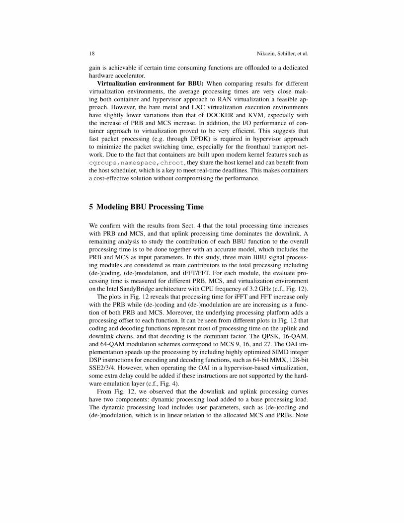
We confirm with the results from Sect. 4 that the total processing time increaseswith PRB and MCS, and that uplink processing time dominates the downlink. Aremaining analysis to study the contribution of each BBU function to the overallprocessing time is to be done together with an accurate model, which includes thePRB and MCS as input parameters. In this study, three main BBU signal process-ing modules are considered as main contributors to the total processing including(de-)coding, (de-)modulation, and iFFT/FFT. For each module, the evaluate pro-cessing time is measured for different PRB, MCS, and virtualization environmenton the Intel SandyBridge architecture with CPU frequency of 3.2 GHz (c.f., Fig. 12).
The plots in Fig. 12 reveals that processing time for iFFT and FFT increase onlywith the PRB while (de-)coding and (de-)modulation are are increasing as a func-tion of both PRB and MCS. Moreover, the underlying processing platform adds aprocessing offset to each function. It can be seen from different plots in Fig. 12 thatcoding and decoding functions represent most of processing time on the uplink anddownlink chains, and that decoding is the dominant factor. The QPSK, 16-QAM,and 64-QAM modulation schemes correspond to MCS 9, 16, and 27. The OAI im-plementation speeds up the processing by including highly optimized SIMD integerDSP instructions for encoding and decoding functions, such as 64-bit MMX, 128-bitSSE2/3/4. However, when operating the OAI in a hypervisor-based virtualization,some extra delay could be added if these instructions are not supported by the hard-ware emulation layer (c.f., Fig. 4).
From Fig. 12, we observed that the downlink and uplink processing curveshave two components: dynamic processing load added to a base processing load.The dynamic processing load includes user parameters, such as (de-)coding and(de-)modulation, which is in linear relation to the allocated MCS and PRBs. Note
Towards a Cloud-Native Radio Access Network 19
0 4 910 13 1617 22 270
100
200
300
400
500
MCS Index
Tim
ing
(us)
PRB 25 DL BBU functions vs MCS
GPP-LL DL: PRB 25 IFFT
GPP-LL DL: PRB 25 Mod
GPP-LL DL: PRB 25 Enc
LXC-LL DL: PRB 25 IFFT
LXC-LL DL: PRB 25 Mod
LXC-LL DL: PRB 25 Enc
DOCKER-LL DL: PRB 25 IFFT
DOCKER-LL DL: PRB 25 Mod
DOCKER-LL DL: PRB 25 Enc
KVM-LL DL: PRB 25 IFFT
KVM-LL DL: PRB 25 Mod
KVM-LL DL: PRB 25 Enc
0 4 910 13 1617 22 270
100
200
300
400
500
MCS Index
Tim
ing
(us)
PRB 50 DL BBU functions vs MCS
GPP-LL DL: PRB 50 IFFT
GPP-LL DL: PRB 50 Mod
GPP-LL DL: PRB 50 Enc
LXC-LL DL: PRB 50 IFFT
LXC-LL DL: PRB 50 Mod
LXC-LL DL: PRB 50 Enc
DOCKER-LL DL: PRB 50 IFFT
DOCKER-LL DL: PRB 50 Mod
DOCKER-LL DL: PRB 50 Enc
KVM-LL DL: PRB 50 IFFT
KVM-LL DL: PRB 50 Mod
KVM-LL DL: PRB 50 Enc
0 4 910 13 1617 22 270
100
200
300
400
500
MCS Index
Tim
ing
(us)
PRB 100 DL BBU functions vs MCS
GPP-LL DL: PRB 100 IFFT
GPP-LL DL: PRB 100 Mod
GPP-LL DL: PRB 100 Enc
LXC-LL DL: PRB 100 IFFT
LXC-LL DL: PRB 100 Mod
LXC-LL DL: PRB 100 Enc
DOCKER-LL DL: PRB 100 IFFT
DOCKER-LL DL: PRB 100 Mod
DOCKER-LL DL: PRB 100 Enc
KVM-LL DL: PRB 100 IFFT
KVM-LL DL: PRB 100 Mod
KVM-LL DL: PRB 100 Enc
0 4 910 13 1617 22 270
500
1000
1500
MCS
Tim
ing
(us)
PRB 25 UL BBU functions vs MCS
GPP-LL UL: PRB 25 FFT
GPP-LL UL: PRB 25 Demod
GPP-LL UL: PRB 25 Dec
LXC-LL UL: PRB 25 FFT
LXC-LL UL: PRB 25 Demod
LXC-LL UL: PRB 25 Dec
DOCKER-LL UL: PRB 25 FFT
DOCKER-LL UL: PRB 25 Demod
DOCKER-LL UL: PRB 25 Dec
KVM-LL UL: PRB 25 FFT
KVM-LL UL: PRB 25 Demod
KVM-LL UL: PRB 25 Dec
0 4 910 13 1617 22 270
500
1000
1500
MCS
Tim
ing
(us)
PRB 50 UL BBU functions vs MCS
GPP-LL UL: PRB 50 FFT
GPP-LL UL: PRB 50 Demod
GPP-LL UL: PRB 50 Dec
LXC-LL UL: PRB 50 FFT
LXC-LL UL: PRB 50 Demod
LXC-LL UL: PRB 50 Dec
DOCKER-LL UL: PRB 50 FFT
DOCKER-LL UL: PRB 50 Demod
DOCKER-LL UL: PRB 50 Dec
KVM-LL UL: PRB 50 FFT
KVM-LL UL: PRB 50 Demod
KVM-LL UL: PRB 50 Dec
0 4 910 13 1617 22 270
500
1000
1500
MCS
Tim
ing
(us)
PRB 100 UL BBU functions vs MCS
GPP-LL UL: PRB 100 FFT
GPP-LL UL: PRB 100 Demod
GPP-LL UL: PRB 100 Dec
LXC-LL UL: PRB 100 FFT
LXC-LL UL: PRB 100 Demod
LXC-LL UL: PRB 100 Dec
DOCKER-LL UL: PRB 100 FFT
DOCKER-LL UL: PRB 100 Demod
DOCKER-LL UL: PRB 100 Dec
KVM-LL UL: PRB 100 FFT
KVM-LL UL: PRB 100 Demod
KVM-LL UL: PRB 100 Dec
Fig. 12 Contribution of (i-)FFT, (de-)modulation, and (de-)coding to the total BBU processing fordifferent PRB, MCS, and platforms
the (de-)coding functions depend also on the channel quality and SNR. The re-maining user parameters, namely DCO coding, PDCCH coding, and scrambling,are modelled as the root mean square error (RMSE) for each platform. The baseprocessing load includes iFFT/FFT cell-processing parameter for each PRB and theplatform-specific parameter relative to the reference GPP platform.
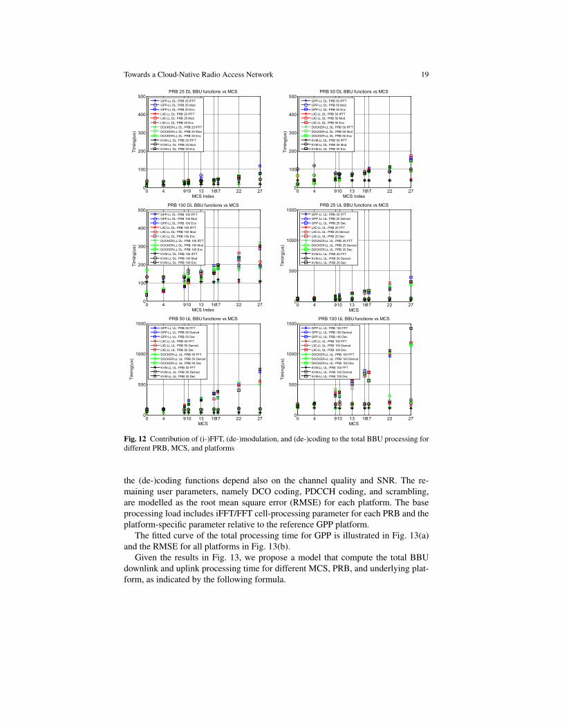
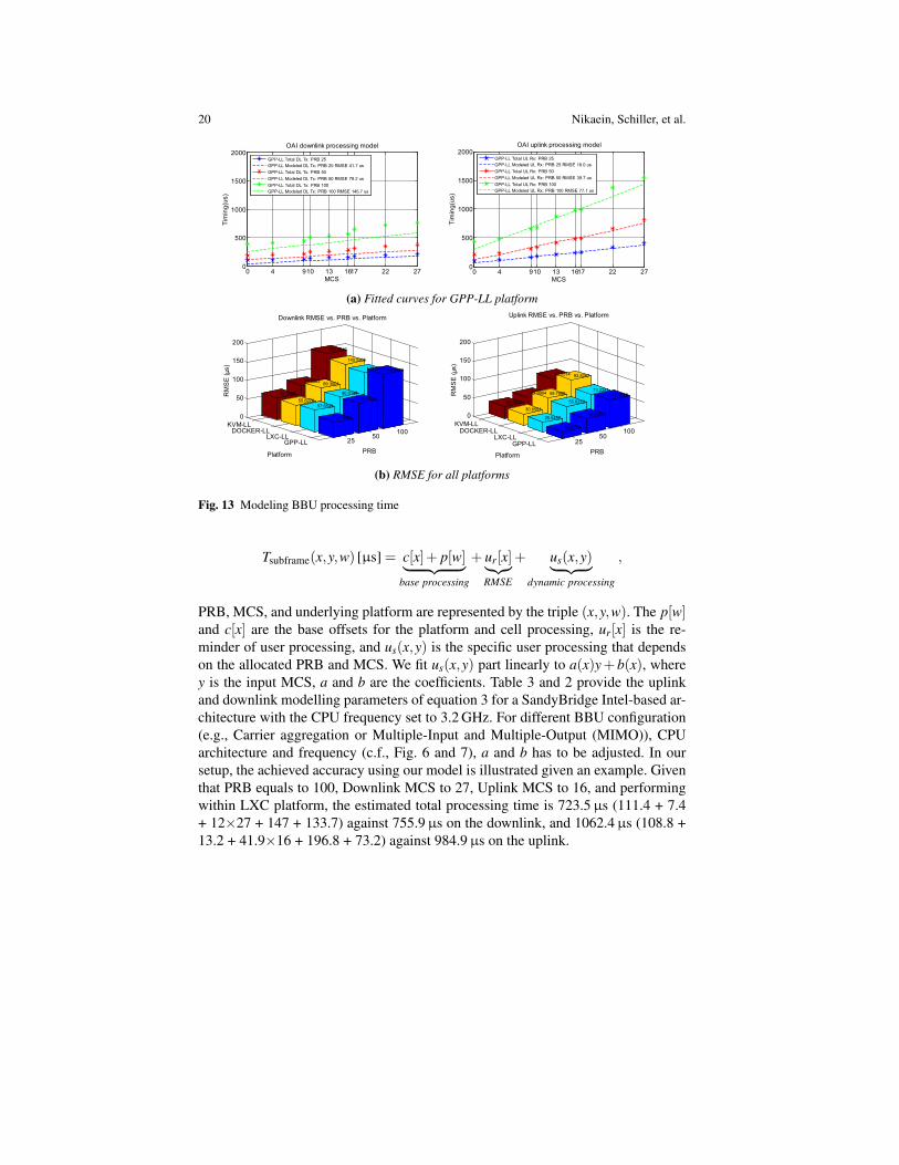
The fitted curve of the total processing time for GPP is illustrated in Fig. 13(a)and the RMSE for all platforms in Fig. 13(b).
Given the results in Fig. 13, we propose a model that compute the total BBUdownlink and uplink processing time for different MCS, PRB, and underlying plat-form, as indicated by the following formula.
20 Nikaein, Schiller, et al.
0 4 910 13 1617 22 270
500
1000
1500
2000
MCS
Timing(us)
OAI downlink processing model
GPP-LL Total DL Tx: PRB 25
GPP-LL Modeled DL Tx: PRB 25 RMSE 41.7 us
GPP-LL Total DL Tx: PRB 50
GPP-LL Modeled DL Tx: PRB 50 RMSE 79.2 us
GPP-LL Total DL Tx: PRB 100
GPP-LL Modeled DL Tx: PRB 100 RMSE 145.7 us
0 4 910 13 1617 22 270
500
1000
1500
2000
MCS
Timing(us)
OAI uplink processing model
GPP-LL Total UL Rx: PRB 25
GPP-LL Modeled UL Rx: PRB 25 RMSE 18.0 us
GPP-LL Total UL Rx: PRB 50
GPP-LL Modeled UL Rx: PRB 50 RMSE 39.7 us
GPP-LL Total UL Rx: PRB 100
GPP-LL Modeled UL Rx: PRB 100 RMSE 77.1 us
(a) Fitted curves for GPP-LL platform
GPP-LLLXC-LL
DOCKER-LLKVM-LL
2550
100
0
50
100
150
200
145.6949133.6943
PRB
79.1506
140.5205
80.0144
41.6588
Downlink RMSE vs. PRB vs. Platform
153.0617
89.3001
57.6543
79.6863
55.6276
Platform
59.3985RM
SE
(µs)
GPP-LLLXC-LL
DOCKER-LLKVM-LL
2550
100
0
50
100
150
200
77.131573.2241
PRB
39.6545
93.8267
55.6216
18.0139
Uplink RMSE vs. PRB vs. Platform
80.0514
59.7996
25.6457
42.9904
30.6591
Platform
32.0933
RM
SE
(µs)
(b) RMSE for all platforms
Fig. 13 Modeling BBU processing time
Tsubframe(x,y,w) [µs] = c[x]+ p[w]︸ ︷︷ ︸base processing
+ ur[x]︸︷︷︸RMSE
+ us(x,y)︸ ︷︷ ︸dynamic processing
,
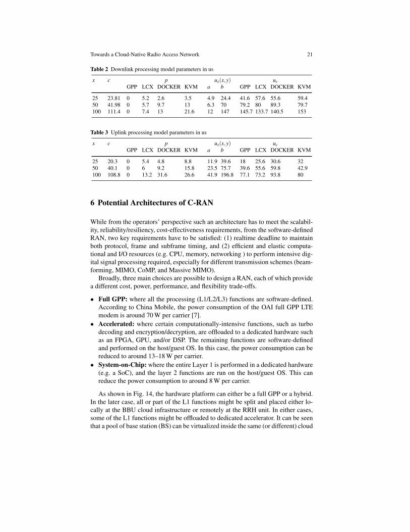
PRB, MCS, and underlying platform are represented by the triple (x,y,w). The p[w]and c[x] are the base offsets for the platform and cell processing, ur[x] is the re-minder of user processing, and us(x,y) is the specific user processing that dependson the allocated PRB and MCS. We fit us(x,y) part linearly to a(x)y+ b(x), wherey is the input MCS, a and b are the coefficients. Table 3 and 2 provide the uplinkand downlink modelling parameters of equation 3 for a SandyBridge Intel-based ar-chitecture with the CPU frequency set to 3.2 GHz. For different BBU configuration(e.g., Carrier aggregation or Multiple-Input and Multiple-Output (MIMO)), CPUarchitecture and frequency (c.f., Fig. 6 and 7), a and b has to be adjusted. In oursetup, the achieved accuracy using our model is illustrated given an example. Giventhat PRB equals to 100, Downlink MCS to 27, Uplink MCS to 16, and performingwithin LXC platform, the estimated total processing time is 723.5µs (111.4 + 7.4+ 12×27 + 147 + 133.7) against 755.9µs on the downlink, and 1062.4µs (108.8 +13.2 + 41.9×16 + 196.8 + 73.2) against 984.9µs on the uplink.
Towards a Cloud-Native Radio Access Network 21
Table 2 Downlink processing model parameters in us
x c p us(x,y) ucGPP LCX DOCKER KVM a b GPP LCX DOCKER KVM
25 23.81 0 5.2 2.6 3.5 4.9 24.4 41.6 57.6 55.6 59.450 41.98 0 5.7 9.7 13 6.3 70 79.2 80 89.3 79.7100 111.4 0 7.4 13 21.6 12 147 145.7 133.7 140.5 153
Table 3 Uplink processing model parameters in us
x c p us(x,y) ucGPP LCX DOCKER KVM a b GPP LCX DOCKER KVM
25 20.3 0 5.4 4.8 8.8 11.9 39.6 18 25.6 30.6 3250 40.1 0 6 9.2 15.8 23.5 75.7 39.6 55.6 59.8 42.9100 108.8 0 13.2 31.6 26.6 41.9 196.8 77.1 73.2 93.8 80
6 Potential Architectures of C-RAN
While from the operators’ perspective such an architecture has to meet the scalabil-ity, reliability/resiliency, cost-effectiveness requirements, from the software-definedRAN, two key requirements have to be satisfied: (1) realtime deadline to maintainboth protocol, frame and subframe timing, and (2) efficient and elastic computa-tional and I/O resources (e.g. CPU, memory, networking ) to perform intensive dig-ital signal processing required, especially for different transmission schemes (beam-forming, MIMO, CoMP, and Massive MIMO).
Broadly, three main choices are possible to design a RAN, each of which providea different cost, power, performance, and flexibility trade-offs.
• Full GPP: where all the processing (L1/L2/L3) functions are software-defined.According to China Mobile, the power consumption of the OAI full GPP LTEmodem is around 70 W per carrier [7].
• Accelerated: where certain computationally-intensive functions, such as turbodecoding and encryption/decryption, are offloaded to a dedicated hardware suchas an FPGA, GPU, and/or DSP. The remaining functions are software-definedand performed on the host/guest OS. In this case, the power consumption can bereduced to around 13–18 W per carrier.
• System-on-Chip: where the entire Layer 1 is performed in a dedicated hardware(e.g. a SoC), and the layer 2 functions are run on the host/guest OS. This canreduce the power consumption to around 8 W per carrier.
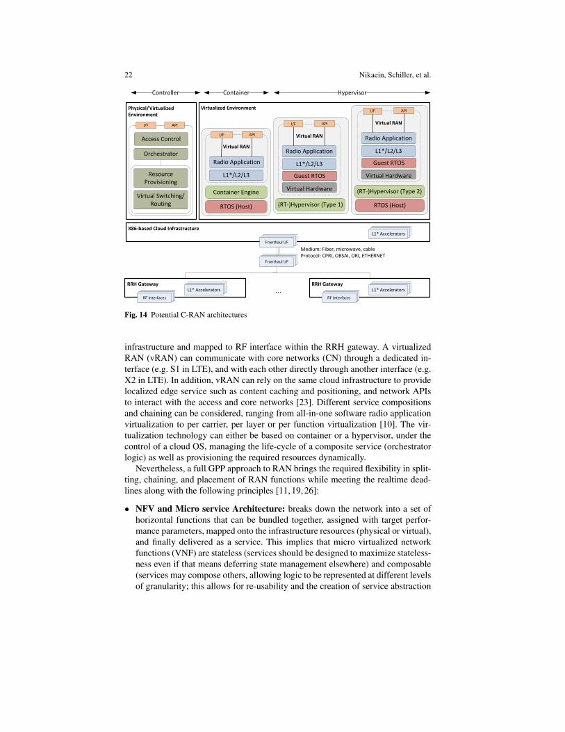
As shown in Fig. 14, the hardware platform can either be a full GPP or a hybrid.In the later case, all or part of the L1 functions might be split and placed either lo-cally at the BBU cloud infrastructure or remotely at the RRH unit. In either cases,some of the L1 functions might be offloaded to dedicated accelerator. It can be seenthat a pool of base station (BS) can be virtualized inside the same (or different) cloud
22 Nikaein, Schiller, et al.
RRH Gateway
X86-based Cloud Infrastructure
(RT-)Hypervisor (Type 1)
Container Hypervisor
(RT-)Hypervisor (Type 2)
RTOS (Host)
RF InterfaceRF InterfaceFronthaul I/F
RTOS (Host)
RF InterfaceRF InterfaceFronthaul I/F
Container Engine
Virtual RAN
APII/F
Guest RTOS
L1*/L2/L3
Radio Application
Virtual Hardware
Virtual RAN
APII/F
Guest RTOS
L1*/L2/L3
Radio Application
Virtual Hardware
Virtual RAN
APII/F
L1*/L2/L3
Radio Application
AcceleratorAcceleratorL1* Accelerators
Resource
Provisioning
Controller
APII/F
Orchestrator
Access Control
Virtual Switching/
Routing
Physical/
Environment
AcceleratorAcceleratorL1* AcceleratorsRF InterfaceRF InterfaceRF Interfaces
RRH GatewayAcceleratorAcceleratorL1* Accelerators
RF InterfaceRF InterfaceRF Interfaces
...
Medium: Fiber, microwave, cable
Protocol: CPRI, OBSAI, ORI, ETHERNET
Virtualized EnvironmentVirtualized
Fig. 14 Potential C-RAN architectures
infrastructure and mapped to RF interface within the RRH gateway. A virtualizedRAN (vRAN) can communicate with core networks (CN) through a dedicated in-terface (e.g. S1 in LTE), and with each other directly through another interface (e.g.X2 in LTE). In addition, vRAN can rely on the same cloud infrastructure to providelocalized edge service such as content caching and positioning, and network APIsto interact with the access and core networks [23]. Different service compositionsand chaining can be considered, ranging from all-in-one software radio applicationvirtualization to per carrier, per layer or per function virtualization [10]. The vir-tualization technology can either be based on container or a hypervisor, under thecontrol of a cloud OS, managing the life-cycle of a composite service (orchestratorlogic) as well as provisioning the required resources dynamically.
Nevertheless, a full GPP approach to RAN brings the required flexibility in split-ting, chaining, and placement of RAN functions while meeting the realtime dead-lines along with the following principles [11, 19, 26]:
• NFV and Micro service Architecture: breaks down the network into a set ofhorizontal functions that can be bundled together, assigned with target perfor-mance parameters, mapped onto the infrastructure resources (physical or virtual),and finally delivered as a service. This implies that micro virtualized networkfunctions (VNF) are stateless (services should be designed to maximize stateless-ness even if that means deferring state management elsewhere) and composable(services may compose others, allowing logic to be represented at different levelsof granularity; this allows for re-usability and the creation of service abstraction
Towards a Cloud-Native Radio Access Network 23
layers and/or platforms). In addition, they can be autonomous (the logic governedby a service resides within an explicit boundary), loosely coupled (dependenciesbetween the underlying logic of a service and its consumers are limited to confor-mance of the service contract), reusable (whether immediate reuse opportunitiesexist, services are designed to support potential reuse), and discoverable (servicesshould allow their descriptions to be discovered and understood by (possibly) hu-mans, service requesters, and service discovery that may be able to make use oftheir logic).11
• Scalability: monitors the RAN events (e.g. workload variations, optimization,relocation, or upgrade) and automatically provision resources without any degra-dations in the required/agreed network performance (scale out/in).
• Reliability: shares the RAN contexts across multiple replicated RAN services tokeep the required redundancy, and distributes the loads among them.
• Placement: optimizes the cost and/or performance by locating the RAN servicesat the specific area subjected to performance, cost, and availability of the RFfront-end and cloud resources.
• Multi-tenancy: shares the available spectrum, radio, and/or infrastructure re-sources across multiple tenants (MNOs, MVNOs) of the same cloud provider,
• Real-time Service: allows to open the RAN edge service environment to autho-rized third-parties to rapidly deploy innovative application and service endpoints.It provides a direct access to real-time radio information for low-latency andhigh-bandwidth service deployed at the network edge [23]. The Real-time Ser-vice shall be automatically configurable to rapidly adjust to varying requirementsand utilization of the cloud environment (c.f., Sect. 7).
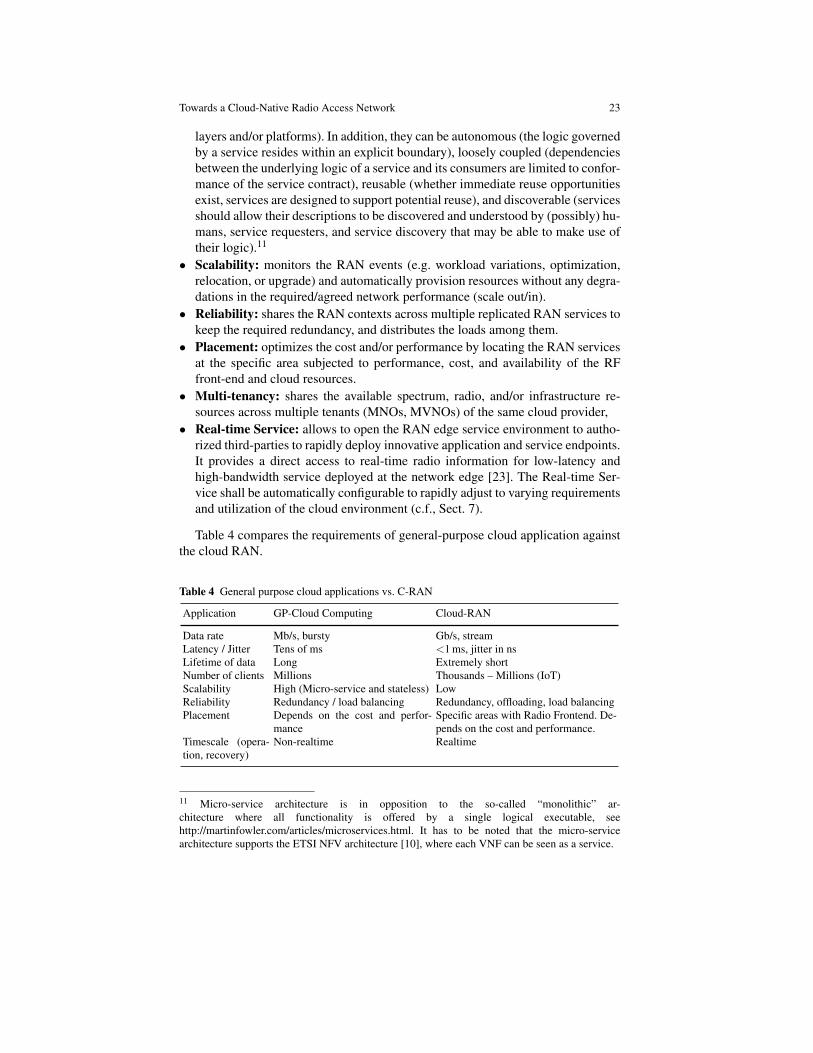
Table 4 compares the requirements of general-purpose cloud application againstthe cloud RAN.
Table 4 General purpose cloud applications vs. C-RAN
Application GP-Cloud Computing Cloud-RAN
Data rate Mb/s, bursty Gb/s, streamLatency / Jitter Tens of ms <1 ms, jitter in nsLifetime of data Long Extremely shortNumber of clients Millions Thousands – Millions (IoT)Scalability High (Micro-service and stateless) LowReliability Redundancy / load balancing Redundancy, offloading, load balancingPlacement Depends on the cost and perfor-
manceSpecific areas with Radio Frontend. De-pends on the cost and performance.
Timescale (opera-tion, recovery)
Non-realtime Realtime
11 Micro-service architecture is in opposition to the so-called “monolithic” ar-chitecture where all functionality is offered by a single logical executable, seehttp://martinfowler.com/articles/microservices.html. It has to be noted that the micro-servicearchitecture supports the ETSI NFV architecture [10], where each VNF can be seen as a service.
24 Nikaein, Schiller, et al.
7 Cloud architecture for the LTE RAN
In cloudified C-RAN, the BBU becomes software-based, hence the concept of C-RAN cloudification, in which the BBU life-cycle is managed through a cloud op-erating system and run over the cloud infrastructure, is sound and may becomean important business connection between mobile telephony operators and cloudproviders. Generally, a cloud provider delivers their (publicly available) servicein the form of three different flavors, namely Infrastructure-as-a-Service (IaaS),Platform-as-a-Service (PaaS) and Software-as-a-Service (SaaS) [22], however, inthe scope of this work, we put a particular focus on the IaaS-based systems. In theIaaS mode, a cloud operator delivers a resource as a so called Virtual Machines(VM), which comes with processing power, RAM, and storage (optionally otherservices too) accessible through the Internet. A user operating a VM system hasthe experience of remote access to an ordinary computer, which is accomplishedthrough a virtualization procedure. Virtualization, which is enabled through a spe-cial software layer called a hypervisor, allows us to simultaneously run many VMs(instances) on a single physical cloud server.
When a Cloud-RAN is deployed on a public cloud, then multiple instances com-pete for the same infrastructure (e.g., computing power, storage, RAM). Hence, inan ordinary setup, we cannot be provided with deadlines for required real-time com-puting. It is therefore necessary to work out new organizational models of publiclyavailable data centers as currently cloud providers do not offer real-time support intheir virtual environment. Here, we briefly present our efforts to allow for real-timesupport in IaaS clouds. We start with an OpenStack installation of a well establishedcloud orchestration system. OpenStack looks after computing power, storage, andnetworking resources of the cloud infrastructure (server pools) and orchestrates theexecution of VMs including (re-) configuration upon initialization or a user request.
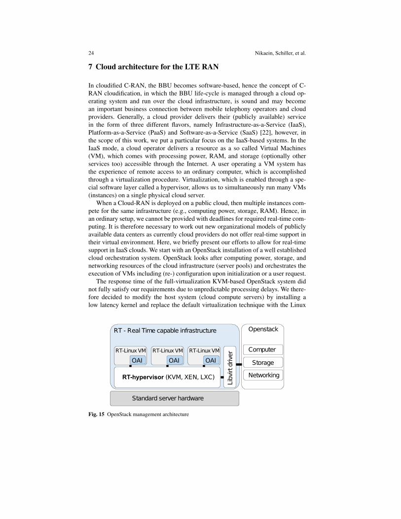
The response time of the full-virtualization KVM-based OpenStack system didnot fully satisfy our requirements due to unpredictable processing delays. We there-fore decided to modify the host system (cloud compute servers) by installing alow latency kernel and replace the default virtualization technique with the Linux
Standard server hardware
Openstack
Lib
virtdriver
RT-hypervisor (KVM, XEN, LXC)
ComputerRT-Linux VM
RT - Real Time capable infrastructure
OAI
RT-Linux VM
OAI
RT-Linux VM
OAI Storage
Networking
Fig. 15 OpenStack management architecture
Towards a Cloud-Native Radio Access Network 25
Containers (LXC) plugin of OpenStack (c.f., Fig. 15). LXC is Operating SystemLevel virtualization providing high performance as all CPU instructions are na-tively executed. Moreover, it allows us for the real-time process prioritization onthe guest operating system (VM). In our case, the lte-softmodem OAI applicationis prioritized real-time within the LXC container using the SCHED DEADLINEor SCHED FIFO schedulers provided by the low latency Linux kernel. Good per-formance of RAN satisfied through LXCs could have a big impact on the securityof cloud infrastructure as LXCs do not provide a good separation of VMs fromphysical servers and should be avoided in the case of less time-critical applicationssuch as EPC, HSS, etc. Therefore a heterogeneous cloud infrastructure maintainingboth real-time (e.g., LXC-based) and general-purpose (e.g., KVM-based) comput-ing regions12 can properly serve purposed of the MNO. The region’s workload isnot know in advance, therefore the cloud provider has to be provided with flexibilityto on-demand re-program the infrastructure when required, e.g., to activate a largernumber of real-time compute nodes for RAN if the current workload exceeds the ca-pacity of the real-time infrastructure, but the overall cloud-global capacity can stillwithhold the workload when reconfigured (i.e., adapting the size of real-time andnon-real-time regions). To this end, we can employ JUJU13 and Metal As a Service(MAAS)14 to program physical cloud compute nodes and provide the concept ofprogrammable cloud that dynamically adjusts the cloud region size.
8 C-RAN Prototype
In this section, we demonstrate a RANaaS proof-of-concept (PoC) (c.f., the archi-tecture presented in Fig. 16). Our cloud infrastructure consists of the OpenStack or-chestrating software with appropriately designed compute servers. Normally, Open-Stack manages large pools of resources, but in our example, it controls a local nanodata-center developed to execute RANaaS. Our compute node is deployed on a com-modity computer running Ubuntu 14.04 with the low latency Linux kernel version3.17, while the OpenStack installation uses the LXC plugin on compute nodes tosupport LXC virtualization. For cloud orchestration OpenStack developed a Heatmodule that provides a human- and machine-accessible service for the managementof the entire life-cycle of a virtual infrastructure and applications. This orchestrationengine relies on text-based templates, called Heat Orchestration Templates (HoTs),to manage multiple composite cloud applications and organize them as a stack ofvirtualized entities (e.g. network, LXCs) called the Heat stack.
Following the LTE protocol stack15, our demonstration has to instantiate an E-UTRAN part, evolved packet core (EPC), and home subscriber server (HSS). The
12 A cloud region is an organizational unit of the cloud containing a pool of cloud workers withspecific properties such as the same configuration or geographical location.13 http://www.ubuntu.com/cloud/tools/juju14 http://www.ubuntu.com/cloud/tools/maas15 Here, the work stack does not refer to Heat and should be understood as a protocol stack.
26 Nikaein, Schiller, et al.
Standard Hardware
(CPU, Memory, NIC)
Low Latency OS
(DEADLINE SCHED)
OpenStack
Keystone Identity
Heat Orchestrator
Neutron Networking
Glance Imaging
Nova Compouting
LXC
GLIBC / FS / libs /bins
Web Services
Resource Provisioning
LXC Virtualization
OAI LTE eNB App
(DEADLINE SCHED API)
HEAT Stack
GLIBC / FS / libs /bins
LXC Virtualization
OAI LTE EPC App
GLIBC / FS / libs /bins
LXC Virtualization
OAI LTE HSS App
GLIBC / FS / libs /bins
Network Provider
(MNO/MVNO)S1/S6/X2
Guest-only
SGI
External
MGT
External
OVS
RF
(EXMIMO2, B210)
Service Orchestrator
Service Manager
User Interface
4G-enabled
apps
LTE
aa
SR
RH
RANaaSSMSO EPCaaSSMSO
IMSaaSSMSO HSSaaSSMSO
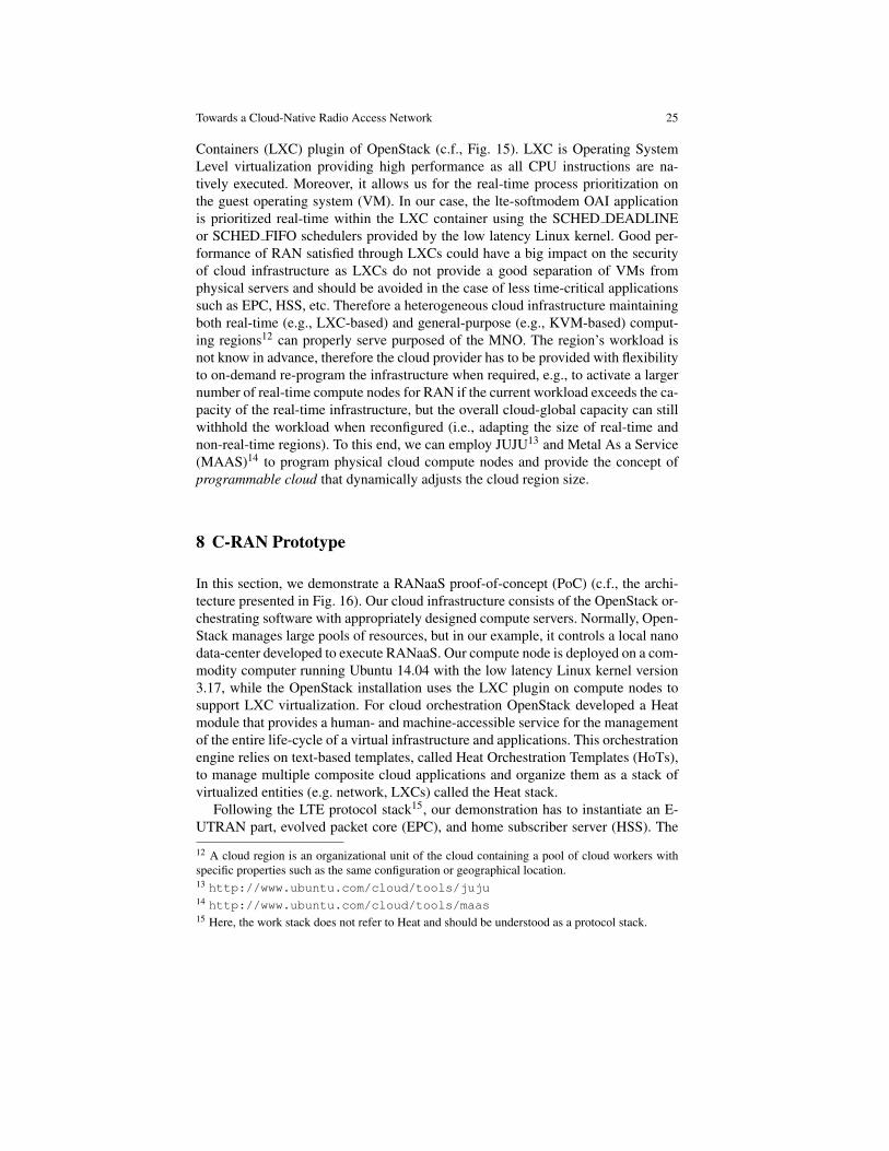
Fig. 16 RANaaS prototype (left) and hardware setup (right)
EPC consists of a mobility management entity (MME) as well as a Serving andPacket data network Gateway (S/P-GW). Mobile Operators (e.g., MNO, MVNO)use the User Interface (UI) to manage the life-cycle of RANaaS. The Service Man-ager (SM) component receives user queries from the UI and manages the cloudexecution through the Service Orchestrator (SO) component, which leverages theuse of the Heat API for cloud orchestration.
In the demonstrated scenario, a HoT file describes the whole virtual infrastruc-ture including the LTE network elements as well as the required network setup tai-lored to a specific business case. Using the HoT template, Heat manages the serviceinstantiation of every required LTE network function implemented in OAI spreadamong multiple VMs. As we previously explained, RANaaS has strict latency andtiming requirements to achieve a required LTE frame/subframe timing. To this end,we use the SCHED DEALINE Linux scheduler to allocates the requested runtime(i.e., CPU time) upon every sub-frame to meet the deadline.
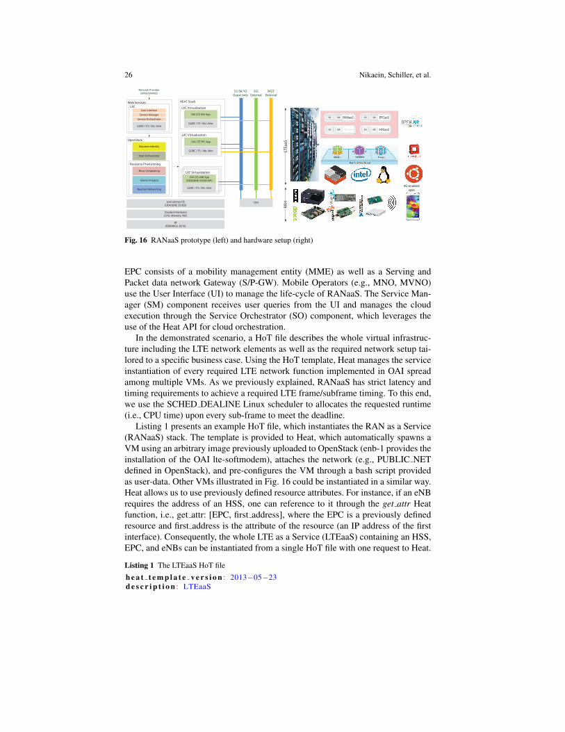
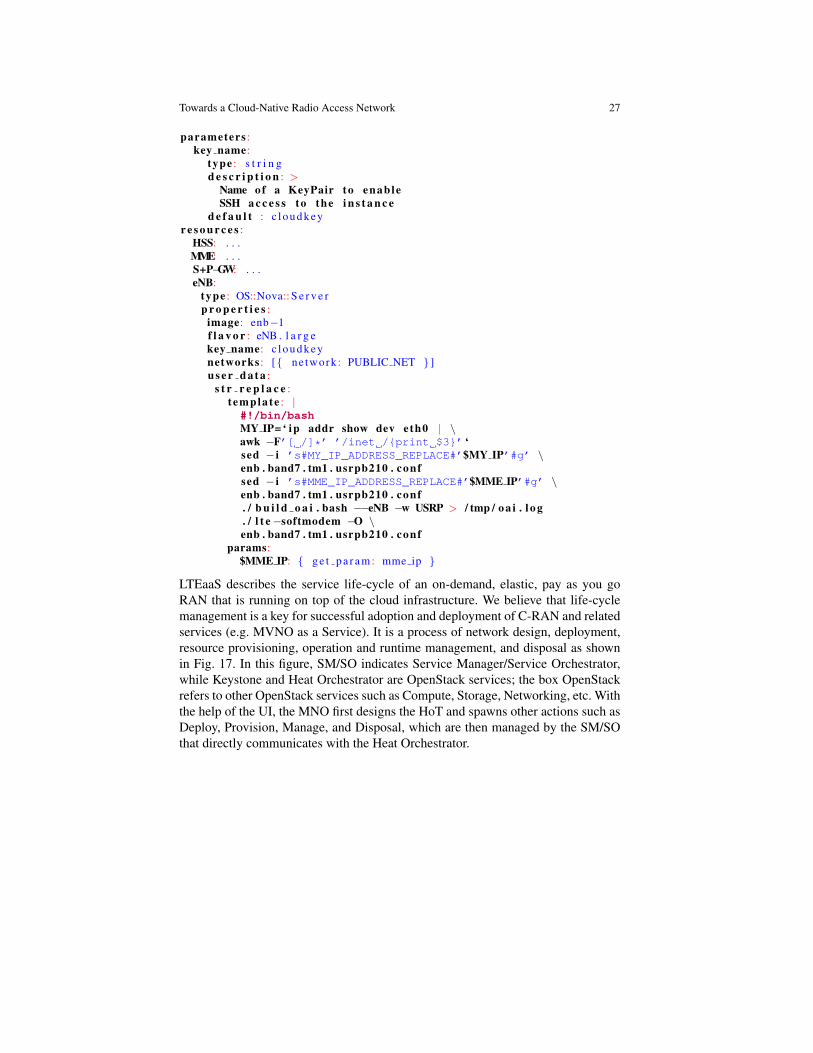
Listing 1 presents an example HoT file, which instantiates the RAN as a Service(RANaaS) stack. The template is provided to Heat, which automatically spawns aVM using an arbitrary image previously uploaded to OpenStack (enb-1 provides theinstallation of the OAI lte-softmodem), attaches the network (e.g., PUBLIC NETdefined in OpenStack), and pre-configures the VM through a bash script providedas user-data. Other VMs illustrated in Fig. 16 could be instantiated in a similar way.Heat allows us to use previously defined resource attributes. For instance, if an eNBrequires the address of an HSS, one can reference to it through the get attr Heatfunction, i.e., get attr: [EPC, first address], where the EPC is a previously definedresource and first address is the attribute of the resource (an IP address of the firstinterface). Consequently, the whole LTE as a Service (LTEaaS) containing an HSS,EPC, and eNBs can be instantiated from a single HoT file with one request to Heat.
Listing 1 The LTEaaS HoT file
h e a t t e m p l a t e v e r s i o n : 2013−05−23d e s c r i p t i o n : LTEaaS
Towards a Cloud-Native Radio Access Network 27
parameters :key name:
type : s t r i n gd e s c r i p t i o n : >
Name of a KeyPair to enableSSH a c c e s s to the i n s t a n c e
d e f a u l t : c l o u d k e yr e s o u r c e s :
HSS: . . .MME: . . .S+P−GW: . . .eNB:
type : OS::Nova:: S e r v e rp r o p e r t i e s :
image: enb−1f l a v o r : eNB . l a r g ekey name: c l o u d k e ynetworks : [{ ne twork : PUBLIC NET } ]u s e r d a t a :
s t r r e p l a c e :t empla te : |#!/bin/bashMY IP= ‘ ip addr show dev eth0 | \awk −F’[ /]*’ ’/inet /{print $3}’ ‘sed − i ’s#MY_IP_ADDRESS_REPLACE#’$MY IP’#g’ \enb . band7 . tm1 . usrpb210 . confsed − i ’s#MME_IP_ADDRESS_REPLACE#’$MME IP’#g’ \enb . band7 . tm1 . usrpb210 . conf. / b u i l d o a i . bash −−eNB −w USRP > / tmp / o a i . l o g. / l t e −softmodem −O \enb . band7 . tm1 . usrpb210 . conf
params:$MME IP: { g e t p a r a m : mme ip }
LTEaaS describes the service life-cycle of an on-demand, elastic, pay as you goRAN that is running on top of the cloud infrastructure. We believe that life-cyclemanagement is a key for successful adoption and deployment of C-RAN and relatedservices (e.g. MVNO as a Service). It is a process of network design, deployment,resource provisioning, operation and runtime management, and disposal as shownin Fig. 17. In this figure, SM/SO indicates Service Manager/Service Orchestrator,while Keystone and Heat Orchestrator are OpenStack services; the box OpenStackrefers to other OpenStack services such as Compute, Storage, Networking, etc. Withthe help of the UI, the MNO first designs the HoT and spawns other actions such asDeploy, Provision, Manage, and Disposal, which are then managed by the SM/SOthat directly communicates with the Heat Orchestrator.
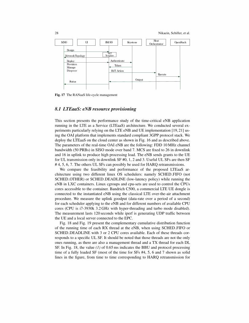
28 Nikaein, Schiller, et al.
MNO KeystoneHeat
OrchestratorOpenStack
Design
UI SM/SO
Authenticate
Token
NetworkTopologyHoT
Template
Deploy
Provision
Manage
Dispose HoT: Action
Execute
OutputStatus
Fig. 17 The RANaaS life-cycle management
8.1 LTEaaS: eNB resource provisioning
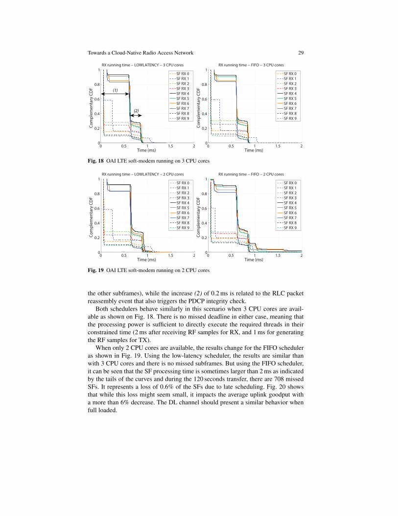
This section presents the performance study of the time-critical eNB applicationrunning in the LTE as a Service (LTEaaS) architecture. We conducted several ex-periments particularly relying on the LTE eNB and UE implementation [19, 21] us-ing the OAI platform that implements standard compliant 3GPP protocol stack. Wedeploy the LTEaaS on the cloud center as shown in Fig. 16 and as described above.The parameters of the real-time OAI eNB are the following: FDD 10 MHz channelbandwidth (50 PRBs) in SISO mode over band 7. MCS are fixed to 26 in downlinkand 16 in uplink to produce high processing load. The eNB sends grants to the UEfor UL transmission only in downlink SF #0, 1, 2 and 3. Useful UL SFs are then SF# 4, 5, 6, 7. The others UL SFs can possibly be used for HARQ retransmissions.
We compare the feasibility and performance of the proposed LTEaaS ar-chitecture using two different linux OS schedulers: namely SCHED FIFO (notSCHED OTHER) or SCHED DEADLINE (low-latency policy) while running theeNB in LXC containers. Linux cgroups and cpu-sets are used to control the CPUscores accessible to the container. Bandrich C500, a commercial LTE UE dongle isconnected to the instantiated eNB using the classical LTE over-the-air attachmentprocedure. We measure the uplink goodput (data-rate over a period of a second)for each scheduler applying to the eNB and for different numbers of available CPUcores (CPU is i7-3930k 3.2 GHz with hyper-threading and turbo mode disabled).The measurement lasts 120 seconds while iperf is generating UDP traffic betweenthe UE and a local server connected to the EPC.
Fig. 18 and Fig. 19 present the complementary cumulative distribution functionof the running time of each RX thread at the eNB, when using SCHED FIFO orSCHED DEADLINE with 3 or 2 CPU cores available. Each of these threads cor-responds to a specific UL SF. It should be noted that those threads are not the onlyones running, as there are also a management thread and a TX thread for each DLSF. In Fig. 18, the value (1) of 0.65 ms indicates the BBU and protocol processingtime of a fully loaded SF (most of the time for SFs #4, 5, 6 and 7 shown as solidlines in the figure, from time to time corresponding to HARQ retransmission for
Towards a Cloud-Native Radio Access Network 29
0 0.5 1 1.5 20
0.2
0.4
0.6
0.8
1
Time (ms)
Co
mp
lem
en
tary
CD
F
RX running time − LOWLATENCY − 3 CPU cores
SF RX 0
SF RX 1
SF RX 2
SF RX 3
SF RX 4
SF RX 5
SF RX 6
SF RX 7
SF RX 8
SF RX 9
0 0.5 1 1.5 20
0.2
0.4
0.6
0.8
1
Time (ms)
Co
mp
lem
en
tary
CD
F
RX running time − FIFO − 3 CPU cores
SF RX 0
SF RX 1
SF RX 2
SF RX 3
SF RX 4
SF RX 5
SF RX 6
SF RX 7
SF RX 8
SF RX 9
(1)
(2)
Fig. 18 OAI LTE soft-modem running on 3 CPU cores
0 0.5 1 1.5 20
0.2
0.4
0.6
0.8
1
Time (ms)
Co
mp
lem
en
tary
CD
F
RX running time − LOWLATENCY − 2 CPU cores
SF RX 0
SF RX 1
SF RX 2
SF RX 3
SF RX 4
SF RX 5
SF RX 6
SF RX 7
SF RX 8
SF RX 9
0 0.5 1 1.5 20
0.2
0.4
0.6
0.8
1
Time (ms)
Co
mp
lem
en
tary
CD
F
RX running time − FIFO − 2 CPU cores
SF RX 0
SF RX 1
SF RX 2
SF RX 3
SF RX 4
SF RX 5
SF RX 6
SF RX 7
SF RX 8
SF RX 9
Fig. 19 OAI LTE soft-modem running on 2 CPU cores
the other subframes), while the increase (2) of 0.2 ms is related to the RLC packetreassembly event that also triggers the PDCP integrity check.
Both schedulers behave similarly in this scenario when 3 CPU cores are avail-able as shown on Fig. 18. There is no missed deadline in either case, meaning thatthe processing power is sufficient to directly execute the required threads in theirconstrained time (2 ms after receiving RF samples for RX, and 1 ms for generatingthe RF samples for TX).
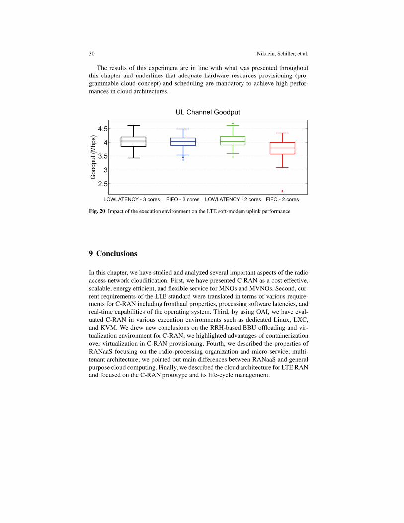
When only 2 CPU cores are available, the results change for the FIFO scheduleras shown in Fig. 19. Using the low-latency scheduler, the results are similar thanwith 3 CPU cores and there is no missed subframes. But using the FIFO scheduler,it can be seen that the SF processing time is sometimes larger than 2 ms as indicatedby the tails of the curves and during the 120 seconds transfer, there are 708 missedSFs. It represents a loss of 0.6% of the SFs due to late scheduling. Fig. 20 showsthat while this loss might seem small, it impacts the average uplink goodput witha more than 6% decrease. The DL channel should present a similar behavior whenfull loaded.
30 Nikaein, Schiller, et al.
The results of this experiment are in line with what was presented throughoutthis chapter and underlines that adequate hardware resources provisioning (pro-grammable cloud concept) and scheduling are mandatory to achieve high perfor-mances in cloud architectures.
2.5
3
3.5
4
4.5
UL Channel Goodput
Go
od
pu
t (M
bp
s)
seroc 2 - OFIFseroc 3 - OFIF seroc 2 - YCNETALWOLseroc 3 - YCNETALWOL
Fig. 20 Impact of the execution environment on the LTE soft-modem uplink performance
9 Conclusions
In this chapter, we have studied and analyzed several important aspects of the radioaccess network cloudification. First, we have presented C-RAN as a cost effective,scalable, energy efficient, and flexible service for MNOs and MVNOs. Second, cur-rent requirements of the LTE standard were translated in terms of various require-ments for C-RAN including fronthaul properties, processing software latencies, andreal-time capabilities of the operating system. Third, by using OAI, we have eval-uated C-RAN in various execution environments such as dedicated Linux, LXC,and KVM. We drew new conclusions on the RRH-based BBU offloading and vir-tualization environment for C-RAN; we highlighted advantages of containerizationover virtualization in C-RAN provisioning. Fourth, we described the properties ofRANaaS focusing on the radio-processing organization and micro-service, multi-tenant architecture; we pointed out main differences between RANaaS and generalpurpose cloud computing. Finally, we described the cloud architecture for LTE RANand focused on the C-RAN prototype and its life-cycle management.
Towards a Cloud-Native Radio Access Network 31
References
1. Alyafawi, I., Schiller, E., Braun, T., Dimitrova, D., Gomes, A., Nikaein, N.: Critical issuesof centralized and cloudified lte-fdd radio access networks. In: Communications (ICC), 2015IEEE International Conference on, pp. 5523–5528 (2015). DOI 10.1109/ICC.2015.7249202
2. Amari LTE 100, a Software LTE Base Station on a PC. http://www.amarisoft.com/3. Berardinelli, G., Ruiz de Temino, L., Frattasi, S., Rahman, M., Mogensen, P.: Ofdma vs. sc-
fdma: performance comparison in local area imt-a scenarios. Wireless Communications, IEEE15(5), 64–72 (2008). DOI 10.1109/MWC.2008.4653134
4. Bhaumik, S., Chandrabose, S.P., Jataprolu, M.K., Kumar, G., Muralidhar, A., Polakos, P.,Srinivasan, V., Woo, T.: Cloudiq: A framework for processing base stations in a data cen-ter. In: Proceedings of the 18th Annual International Conference on Mobile Computing andNetworking, Mobicom ’12, pp. 125–136. ACM, New York, NY, USA (2012). DOI 10.1145/2348543.2348561. URL http://doi.acm.org/10.1145/2348543.2348561
5. Chanclou, P., Pizzinat, A., Le Clech, F., Reedeker, T.L., Lagadec, Y., Saliou, F., Le Guyader,B., Guillo, L., Deniel, Q., Gosselin, S., Le, S., Diallo, T., Brenot, R., Lelarge, F., Marazzi, L.,Parolari, P., Martinelli, M., O’Dull, S., Gebrewold, S., Hillerkuss, D., Leuthold, J., Gavioli,G., Galli, P.: Optical fiber solution for mobile fronthaul to achieve cloud radio access network.In: Future Network and Mobile Summit (FutureNetworkSummit), 2013, pp. 1–11 (2013)
6. Checko, A., Christiansen, H., Yan, Y., Scolari, L., Kardaras, G., Berger, M., Dittmann, L.:Cloud ran for mobile networks #x2014;a technology overview. Communications SurveysTutorials, IEEE 17(1), 405–426 (2015). DOI 10.1109/COMST.2014.2355255
7. China Mobile Research Institute: C-RAN White Paper: The Road Towards Green RAN.http://labs.chinamobile.com/cran (2013)
8. Costa-Perez, X., Swetina, J., Guo, T., Mahindra, R., Rangarajan, S.: Radio access networkvirtualization for future mobile carrier networks. Communications Magazine, IEEE 51(7),27–35 (2013). DOI 10.1109/MCOM.2013.6553675
9. Dahlman, E., Parkvall, S., Skold, J.: 4G LTE/LTE-Advanced for Mobile Broadband, 1st edn.Academic Press (2011)
10. ETSI: Network Functions Virtualisation (NFV), White paper. Tech. rep., ETSI (2014)11. EU FP7 Mobile Cloud Networking public deliverable D2.5: Final Overall Architecture Defi-
nition. Tech. rep., EU (2015)12. EURECOM: Open Air Interface. http://www.openairinterface.org/13. Haberland, B., Derakhshan, F., Grob-Lipski, H., Klotsche, R., Rehm, W., Schefczik, P., Soell-
ner, M.: Radio Base Stations in the Cloud. Bell Labs Technical Journal 18(1), 129–152 (2013)14. Interworking and JOINt Design of an Open Access and Backhaul Network Architecture for
Small Cells based on Cloud Networks (iJOIN): an FP7 STREP project co-funded by the Eu-ropean Commission. http://www.ict-ijoin.eu/
15. Mobile Cloud Networking (MCN): an FP7 IP project co-funded by the European Commission.http://www.mobile-cloud-networking.eu.
16. NGMN: Further Study on Critical C-RAN Technologies (v0.6). Tech. rep., The Next Gener-ation Mobile Networks (NGMN) Alliance (2013)
17. NGMN: Suggestions on Potential Solutions to C-RAN by NGMN Alliance. Tech. rep., TheNext Generation Mobile Networks (NGMN) Alliance (2013)
18. Nikaein, N.: Processing radio access network functions in the cloud: Critical issues and mod-eling. In: Proceedings of the 6th International Workshop on Mobile Cloud Computing andServices, MCS’15, pp. 36–43. ACM, New York, NY, USA (2015)
19. Nikaein, N., Knopp, R., Gauthier, L., Schiller, E., Braun, T., Pichon, D., Bonnet, C.,Kaltenberger, F., Nussbaum, D.: Demo – Closer to Cloud-RAN: RAN as a Service. Pro-ceedings of ACM MOBICOM Demonstrations (2015)
20. Nikaein, N., Knopp, R., Kaltenberger, F., Gauthier, L., Bonnet, C., Nussbaum, D., Ghaddab,R.: OpenAirInterface 4G: an open LTE network in a PC. In: Proceedings of the 20th AnnualInternational Conference on Mobile Computing and Networking, MobiCom ’14, pp. 305–308.ACM, New York, NY, USA (2014). DOI 10.1145/2639108.2641745
32 Nikaein, Schiller, et al.
21. Nikaein, N., Schiller, E., Favraud, R., Katsalis, K., Stavropoulos, D., Alyafawi, I., Zhao, Z.,Braun, T., Korakis, T.: Network store: Exploring slicing in future 5g networks. In: Proceed-ings of the 10th International Workshop on Mobility in the Evolving Internet Architecture,MobiArch’15, pp. 8–13. ACM, New York, NY, USA (2015)
22. Oracle: Oracle Cloud, Enterprise-Grade Cloud Solutions: SaaS, PaaS, and IaaS. https://cloud.oracle.com/home
23. Patel, M., Joubert, J., Ramos, J.R., Sprecher, N., Abeta, S., Neal, A.: Mobile-Edge Computing.Tech. rep., ETSI, white paper (2014)
24. Scalable and Adaptive Internet Solutions (SAIL): an FP7 IP project co-funded by the EuropeanCommission. http://www.sail-project.eu
25. Schooler, R.: Transforming Networks with NFV & SDN. Intel Architecture Group (2013)26. Wilder, B.: Cloud Architecture Patterns. O’Reilly (2012)27. Wubben, D., Rost, P., Bartelt, J., Lalam, M., Savin, V., Gorgoglione, M., Dekorsy, A., Fettweis,
G.: Benefits and impact of cloud computing on 5g signal processing: Flexible centralizationthrough cloud-ran. Signal Processing Magazine, IEEE 31(6), 35–44 (2014). DOI 10.1109/MSP.2014.2334952