Embed Size (px)
Citation preview
Towards a simulation methodology for prediction of airborne wear particles from disc brakes
Jens Wahlström
Licentiate thesis Department of Machine Design Royal Institute of Technology SE-100 44 Stockholm
TRITA – MMK 2009:15 ISSN 1400-1179
ISRN/KTH/MMK/R-09/15-SE ISBN 978-91-7415-391-0
TRITA – MMK 2009:15 ISSN 1400-1179 ISRN/KTH/MMK/R-09/15-SE ISBN 978-91-7415-391-0
Towards a simulation methodology for prediction of airborne wear particles from disc brakes
Jens Wahlström
Licentiate thesis
Academic thesis that, with the approval of the Royal institute of technology, will be presented for public review in fulfillment of the requirements for a Licentiate of Engineering in Machine Design. Public review: the Royal institute of technology, room B242, Brinellvägen 83 floor 2, Stockholm, on October 2, 2009, at 10:00
Abstract
During braking, both the rotor and the pads in disc brakes are worn. Since disc brakes are not sealed, some of the wear particles generated can become airborne. Several studies have found an association between adverse health effects and the concentration of particles in the atmosphere, so it is of interest to improve our knowledge of the airborne wear particles generated by disc brakes. However, in field tests it is difficult to distinguish these particles from others in the surrounding environment, so it may be preferable to use laboratory test stands and/or simulation models to study the amount of airborne wear particles generated.
This thesis deals with a simulation methodology for prediction of airborne wear particles from disc brakes and three experimental methods for testing disc brake materials with focus on airborne wear particles. The four appended papers discuss the possibility to both measure and predict the number and size distribution of airborne wear particles that originate from the pad to rotor contact. The objective is to develop a simulation methodology that predicts the number and size distribution of airborne wear particles from disc brakes.
Paper A describes how a modified pin-on-disc machine was used to study airborne wear particles originating from different disc brake materials. The results indicate that the test setup can be used to measure and rank the number concentration and size distribution of the airborne wear particles generated.
Paper B describes a disc brake assembly test stand for measurements of airborne wear particles from disc brakes. The results indicate that the test setup can be used to measure the number concentration and size distribution of airborne wear particles generated from disc brake materials. The results also indicate a promising ability to rank different pad/rotor material combinations with respect to the number concentration of airborne wear particles.
Paper C compares measurements made in passenger car field tests with measurements made in a disc brake assembly test stand and in a pin-on-disc machine. A promising correlation between the three different test methods is found.
Paper D presents a simulation methodology for predicting the number and size distribution of airborne wear particles using finite element analysis (FEA). The simulated number distribution is compared with experimental measurements at component level. The result indicates that the proposed methodology may be used to predict the number concentration and size distribution of airborne particles generated in the pad-to-rotor contact.
Keywords: Disc brakes, Airborne wear particles, Particle coefficient, Friction

Preface
The research presented here was carried out between August 2007 and October 2009 in the department of Machine Design at the Royal Institute of Technology, Stockholm, Sweden. I would like to express my gratitude to all the people that have helped me.
First of all, I wish to thank my supervisor Ulf Olofsson and SAAB Automobile for giving me the chance to write this thesis.
Thanks to all graduate students in room A419 for making work more fun and inspiring. Special thanks go to my co-writer Anders Söderberg for valuable discussions and pointers.
Stockholm, September 2009
Jens Wahlström

List of appended papers
This thesis consists of a summary and the following four appended papers:
Paper A Wahlström J, Söderberg A, Olander L, Jansson A, Olofsson U. 2009. A pin-on-disc simulation of airborne wear particles from disc brakes. Submitted to Journal of Wear.
Paper B Wahlström J, Söderberg A, Olander L, Olofsson U. 2009. A disc brake test stand for measurements of airborne wear particles. Lubrication Science, 21, 241–252.
Paper C Wahlström J, Söderberg A, Olander L, Jansson A, Olofsson U. 2009. Airborne wear particles from passenger car disc brakes: a comparison of measurements from field tests, a disc brake assembly test stand, and a pin-on-disc machine. Proc. IMechE Part J: Journal of Engineering Tribology, 223. In press.
Paper D Wahlström J, Söderberg A, Olofsson U. 2009. Simulation of airborne particles from disc brakes. SAE Technical Paper 2009-01-3040.

The author's contributions to the appended papers
The work presented in this thesis was initiated and supervised by Professor Ulf Olofsson.
Paper A The author contributed to the writing, experimental work, and evaluation.
Paper B The author performed most of the planning, writing, experimental work, and evaluation.
Paper C The author performed most of the writing and contributed to the planning, experimental work, and evaluation.
Paper D The author performed most of the writing and experimental work, and contributed to the planning, simulation, and evaluation.
Contents
1 Introduction .........................................................................................................................................1
1.1 Disc brakes..................................................................................................................................1
1.2 Airborne particles.......................................................................................................................2
1.3 Particle coefficient......................................................................................................................4
1.4 Research objectives and proposed methodology ..................................................................5
2 Experimental methods .......................................................................................................................6
2.1 Particle instruments ...................................................................................................................6
2.2 Clean air technology ..................................................................................................................7
2.3 Pin-on-disc machine ..................................................................................................................7
2.4 Disc brake assembly test stand.................................................................................................8
2.5 Passenger car field test...............................................................................................................9
3 Airborne wear modeling...................................................................................................................10
4 Summary of results of appended papers........................................................................................11
4.1 Simulation methodology .........................................................................................................11
4.2 Experimental methods ............................................................................................................11
5 Discussion ..........................................................................................................................................12
6 Conclusions........................................................................................................................................14
7 References ..........................................................................................................................................15
Appended papers
A. A pin-on-disc simulation of airborne wear particles from disc brakes
B. A disc brake test stand for measurements of airborne wear particles
C. Airborne wear particles from passenger car disc brakes: a comparison of measurements from field tests, a disc brake assembly test stand, and a pin-on-disc machine
D. Simulation of airborne particles from disc brakes

1
1 Introduction
This thesis deals with three experimental methods for testing disc brake materials and a simulation methodology for prediction of airborne wear particles from disc brakes. The four appended papers discuss the possibility of both measuring and predicting the number concentration and size distribution of airborne wear particles originating from the pad-to-rotor contact.
An introduction to disc brakes is given in section 1.1. Airborne particles are an essential part of the thesis, so section 1.2 introduces the necessary terminology and provides an overview of the origins of atmospheric particles; disc brakes as a source of airborne particles are also discussed. In this thesis, a particle coefficient is used to predict the number of airborne wear particles generated in the pad-to-rotor contact. This coefficient is discussed in section 1.3. The research objectives and proposed methodology are presented in section 1.4.
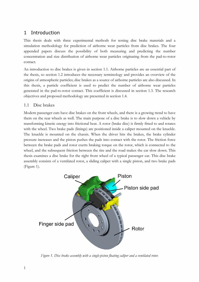
1.1 Disc brakes Modern passenger cars have disc brakes on the front wheels, and there is a growing trend to have them on the rear wheels as well. The main purpose of a disc brake is to slow down a vehicle by transforming kinetic energy into frictional heat. A rotor (brake disc) is firmly fitted to and rotates with the wheel. Two brake pads (linings) are positioned inside a caliper mounted on the knuckle. The knuckle is mounted on the chassis. When the driver hits the brakes, the brake cylinder pressure increases and the piston pushes the pads into contact with the rotor. The friction force between the brake pads and rotor exerts braking torque on the rotor, which is connected to the wheel, and the subsequent friction between the tire and the road makes the car slow down. This thesis examines a disc brake for the right front wheel of a typical passenger car. This disc brake assembly consists of a ventilated rotor, a sliding caliper with a single piston, and two brake pads (Figure 1).
Figure 1. Disc brake assembly with a single-piston floating caliper and a ventilated rotor.
2
Most rotors used in passenger cars are made of gray cast iron. The brake pads can be made of many different material combinations, but are essentially constructed of four components: a binder, reinforcing fibers, fillers, and frictional additives [1]. The main task of the binder, which is made of polymer-based resin, is to hold the components of the brake pad together. The main task of the reinforcing fibers, which can be made of metal, glass, carbon, and ceramic fibers, is to give mechanical strength to the brake pad. Fillers are used partly to reduce cost and partly to alter the brake pad properties, for example, to reduce noise and improve thermal properties. They can be made of barium sulfate and mica. Frictional additives, such as graphite, metal sulfides, and metal oxides/silicates, are used to control the friction and wear.
Brake pads are grouped into three categories: non-asbestos organic (NAO), semi-metallic, and low metallic. According to Sanders et al. [2], NAO-type brake pads exhibit relatively low brake noise and low wear rates, but lose braking capacity at high temperature. Semi-metallic brake pads have a high steel fiber and iron powder content and low wear, but are noisier than the other types. Low-metallic brake pads have a relatively high abrasive content, which results in high friction and good braking capacity at high temperatures. The present work examines low-metallic and NAO-type brake pads.
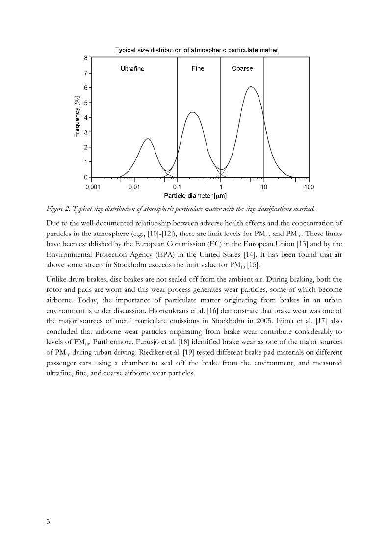
1.2 Airborne particles Particulate matter (PM) is made up of solid or liquid particles suspended in a gas or liquid; atmospheric aerosols refer to the particles and gas together. The aerodynamic diameter is the diameter of a sphere of unit density that has the same gravitational settling velocity as the particle in question. In this thesis, particles with an aerodynamic diameter less than 10 µm (PM10) are divided into a coarse fraction (>1 µm), a fine fraction (<1 µm, PM1), and an ultrafine fraction (<0.1 µm, PM0.1). Figure 2 (modified from the Environmental Protection Agency [3]) presents typical size distributions of atmospheric particulate matter with the size classification marked.
The coarse particles mainly originate from natural sources such as dust and pollen, but also from anthropogenic sources (e.g., mechanical processes). In an urban environment, these anthropogenic particles can come from various sources, such as demolition and construction [4], resuspended road dust [5], wheel to rail contact [6],[7], and tire-to-road contact [8],[9].
Fine and ultrafine particles are usually formed from gases, mainly due to fossil fuel combustion. Primary fine particles are introduced directly to the atmosphere and secondary fine particles are formed by chemical reactions in the atmosphere. Ultrafine particles, such as metallic vapor, coagulate (or condense) without chemical reactions from primary fine particles. The combustion of gasoline and diesel forms fine particles, whereas the combustion of coal and heavy fuel oil yields both fine and coarse particles.
3
Figure 2. Typical size distribution of atmospheric particulate matter with the size classifications marked.
Due to the well-documented relationship between adverse health effects and the concentration of particles in the atmosphere (e.g., [10]-[12]), there are limit levels for PM2.5 and PM10. These limits have been established by the European Commission (EC) in the European Union [13] and by the Environmental Protection Agency (EPA) in the United States [14]. It has been found that air above some streets in Stockholm exceeds the limit value for PM10 [15].
Unlike drum brakes, disc brakes are not sealed off from the ambient air. During braking, both the rotor and pads are worn and this wear process generates wear particles, some of which become airborne. Today, the importance of particulate matter originating from brakes in an urban environment is under discussion. Hjortenkrans et al. [16] demonstrate that brake wear was one of the major sources of metal particulate emissions in Stockholm in 2005. Iijima et al. [17] also concluded that airborne wear particles originating from brake wear contribute considerably to levels of PM10. Furthermore, Furusjö et al. [18] identified brake wear as one of the major sources of PM10 during urban driving. Riediker et al. [19] tested different brake pad materials on different passenger cars using a chamber to seal off the brake from the environment, and measured ultrafine, fine, and coarse airborne wear particles.
4
1.3 Particle coefficient This section derives and discusses the particle coefficient proposed by Olofsson et al. [20]. The pad-to-rotor interface can be classified as a conformal dry sliding contact. The most commonly used model for predicting wear in sliding contacts is the linear wear law proposed by Holm-Archard ([21], [22]):
PkSV
⋅= (1)
where k is the wear coefficient, V is the wear volume, P is the applied normal load, and S is the sliding distance. The airborne wear volume, VD, for particles of characteristic diameter D can be written as a fraction, cD, of the total wear volume:
VcV DD ⋅= (2)
Combining (1) and (2) gives a wear equation for predicting airborne wear volume:
PkS
VD
D ⋅= (3)
where kD = cD· k is the contact-pair–dependent particle coefficient. If the airborne wear particles are assumed to be spherical, the airborne volume can be expressed as
3
6DπNV DD ⋅= (4)
where ND is the number of airborne wear particles of characteristic diameter D. Combining (3) and (4) gives the particle rate:
3
6Dπ
kPS
ND
D ⋅⋅= (5)
5
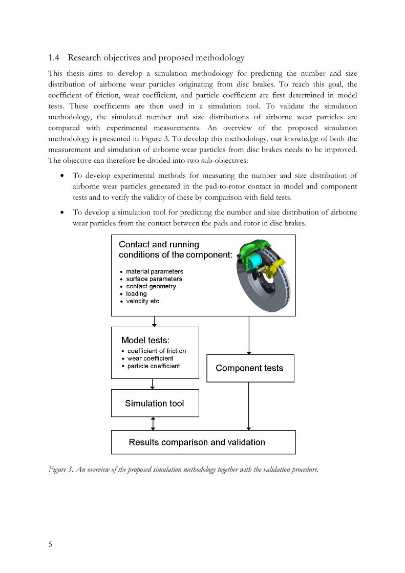
1.4 Research objectives and proposed methodology This thesis aims to develop a simulation methodology for predicting the number and size distribution of airborne wear particles originating from disc brakes. To reach this goal, the coefficient of friction, wear coefficient, and particle coefficient are first determined in model tests. These coefficients are then used in a simulation tool. To validate the simulation methodology, the simulated number and size distributions of airborne wear particles are compared with experimental measurements. An overview of the proposed simulation methodology is presented in Figure 3. To develop this methodology, our knowledge of both the measurement and simulation of airborne wear particles from disc brakes needs to be improved. The objective can therefore be divided into two sub-objectives:
• To develop experimental methods for measuring the number and size distribution of airborne wear particles generated in the pad-to-rotor contact in model and component tests and to verify the validity of these by comparison with field tests.
• To develop a simulation tool for predicting the number and size distribution of airborne wear particles from the contact between the pads and rotor in disc brakes.
Figure 3. An overview of the proposed simulation methodology together with the validation procedure.
6
2 Experimental methods
Although several studies have focused on wear and friction at the pad-to-rotor interface in laboratory test stands [23]–[25], few have focused on the online measurement of airborne wear particles [2],[26]. To improve our understanding of airborne wear particles, known experimental methods for testing disc brake materials at different test levels have been modified and used in this thesis. This section describes the experimental methods used. Subsection 2.1 gives an overview of the particle instruments used to measure airborne wear particles, while 2.2 describes the technology used to control the cleanliness of the air surrounding the test specimens in the test stands. A pin-on-disc machine is presented in 2.3, a disc brake assembly test stand in 2.4, and a vehicle instrumented for field tests in 2.5.
2.1 Particle instruments The main instrument used to measure the particles was a Grimm 1.109 aerosol spectrometer. This measures airborne particles from 0.25 to 32 µm in 31 size intervals, in concentrations ranging from 1000 to 2 × 10⁹ particles/m3, and at a sample flow rate of 0.072 m3/h [27]. The measured particle concentration is recorded every six seconds. As an optical particle counter is sensitive to the shape and refractive index of the particles, the measured particle sizes and thus number distributions are approximate [28].
The second particle instrument used was a DustTrak counter, which reports the mass concentration in mg/m3. This is a photometer that can measure particle concentrations corresponding to the respirable, PM10, PM2.5, and PM1.0 size fractions. It is calibrated using solid particles with a density of 2650 kg/m3. It was used in these experiments without any pre-precipitator, and thus measured particles between 0.1 and 10 µm. The mass concentration is recorded every five seconds. The instrument is calibrated using standardized test dust, which has a different size distribution, density, and refractive index from the particles measured here. Thus, the output of this instrument can only be used as a relative measure, but is nonetheless useful in seeing the changes in generated particle mass over time [29].
The third particle instrument was a PTrak counter [30]. This condensation nucleus counter measures the number concentration of airborne particles between 0.02 and 1 µm. For both the upper and lower limits, the 50% cutoff in counting is given. There is no size resolution between the upper and lower limits and the particle concentration is recorded once per second.
The fourth instrument used at the air outlet was a scanning mobility particle sizer (SMPS) [31]. The SMPS combines an electrostatic classifier (TSI 3071) with a particle counter (TSI CPC 3010). The particles are charged in a controlled manner and then sequentially classified according to their electrical mobility. With the controlled charging, particle electrical mobility corresponds to particle size. The counter subsequently registers the particles in sequential size classes. The counter is a condensation nuclei counter that uses condensation to optically count particles as small as 10 nm.
7
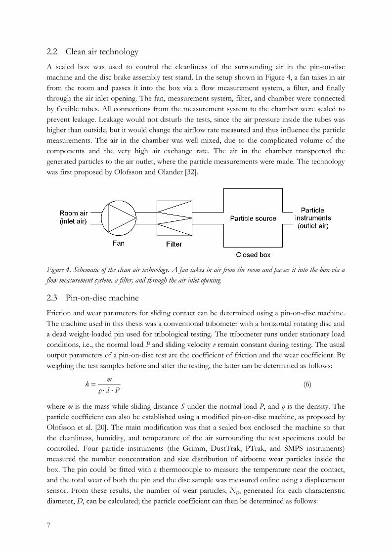
2.2 Clean air technology A sealed box was used to control the cleanliness of the surrounding air in the pin-on-disc machine and the disc brake assembly test stand. In the setup shown in Figure 4, a fan takes in air from the room and passes it into the box via a flow measurement system, a filter, and finally through the air inlet opening. The fan, measurement system, filter, and chamber were connected by flexible tubes. All connections from the measurement system to the chamber were sealed to prevent leakage. Leakage would not disturb the tests, since the air pressure inside the tubes was higher than outside, but it would change the airflow rate measured and thus influence the particle measurements. The air in the chamber was well mixed, due to the complicated volume of the components and the very high air exchange rate. The air in the chamber transported the generated particles to the air outlet, where the particle measurements were made. The technology was first proposed by Olofsson and Olander [32].
Figure 4. Schematic of the clean air technology. A fan takes in air from the room and passes it into the box via a flow measurement system, a filter, and through the air inlet opening.
2.3 Pin-on-disc machine Friction and wear parameters for sliding contact can be determined using a pin-on-disc machine. The machine used in this thesis was a conventional tribometer with a horizontal rotating disc and a dead weight-loaded pin used for tribological testing. The tribometer runs under stationary load conditions, i.e., the normal load P and sliding velocity v remain constant during testing. The usual output parameters of a pin-on-disc test are the coefficient of friction and the wear coefficient. By weighing the test samples before and after the testing, the latter can be determined as follows:
PSρ
mk⋅⋅
= (6)
where m is the mass while sliding distance S under the normal load P, and ρ is the density. The particle coefficient can also be established using a modified pin-on-disc machine, as proposed by Olofsson et al. [20]. The main modification was that a sealed box enclosed the machine so that the cleanliness, humidity, and temperature of the air surrounding the test specimens could be controlled. Four particle instruments (the Grimm, DustTrak, PTrak, and SMPS instruments) measured the number concentration and size distribution of airborne wear particles inside the box. The pin could be fitted with a thermocouple to measure the temperature near the contact, and the total wear of both the pin and the disc sample was measured online using a displacement sensor. From these results, the number of wear particles, ND, generated for each characteristic diameter, D, can be calculated; the particle coefficient can then be determined as follows:
8
6
3DπPS
Nk DD ⋅= (7)
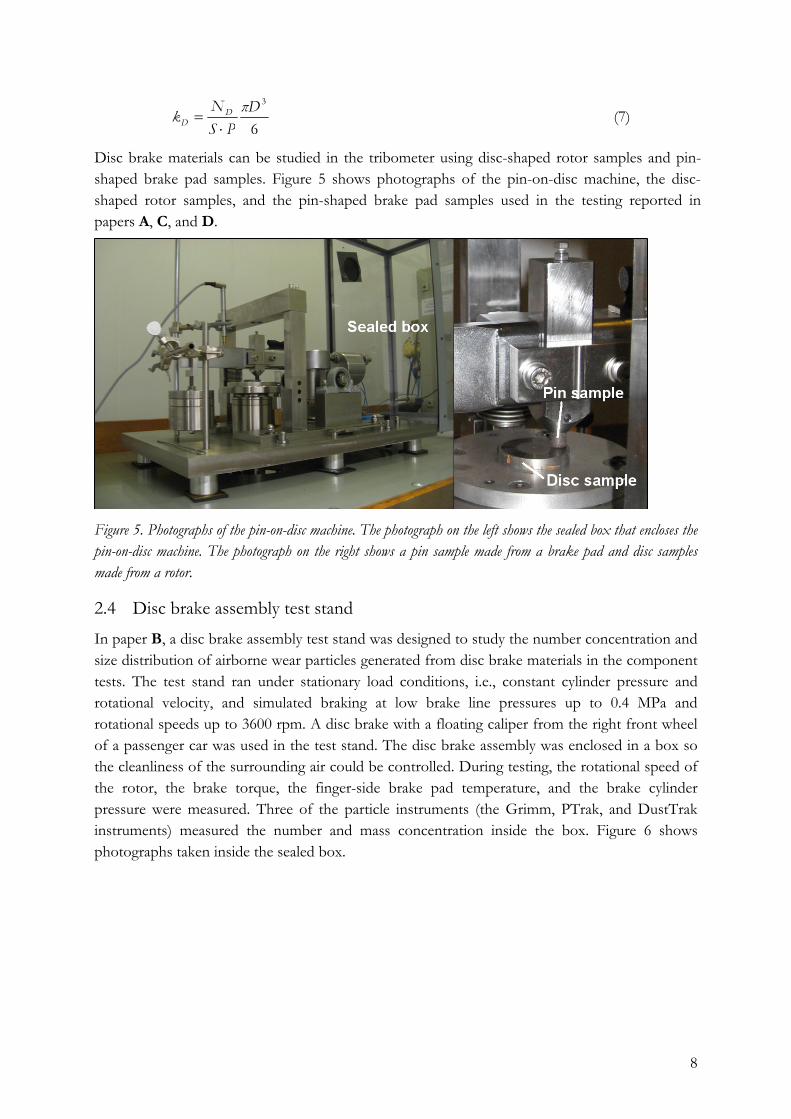
Disc brake materials can be studied in the tribometer using disc-shaped rotor samples and pin-shaped brake pad samples. Figure 5 shows photographs of the pin-on-disc machine, the disc-shaped rotor samples, and the pin-shaped brake pad samples used in the testing reported in papers A, C, and D.
Figure 5. Photographs of the pin-on-disc machine. The photograph on the left shows the sealed box that encloses the pin-on-disc machine. The photograph on the right shows a pin sample made from a brake pad and disc samples made from a rotor.
2.4 Disc brake assembly test stand In paper B, a disc brake assembly test stand was designed to study the number concentration and size distribution of airborne wear particles generated from disc brake materials in the component tests. The test stand ran under stationary load conditions, i.e., constant cylinder pressure and rotational velocity, and simulated braking at low brake line pressures up to 0.4 MPa and rotational speeds up to 3600 rpm. A disc brake with a floating caliper from the right front wheel of a passenger car was used in the test stand. The disc brake assembly was enclosed in a box so the cleanliness of the surrounding air could be controlled. During testing, the rotational speed of the rotor, the brake torque, the finger-side brake pad temperature, and the brake cylinder pressure were measured. Three of the particle instruments (the Grimm, PTrak, and DustTrak instruments) measured the number and mass concentration inside the box. Figure 6 shows photographs taken inside the sealed box.
9
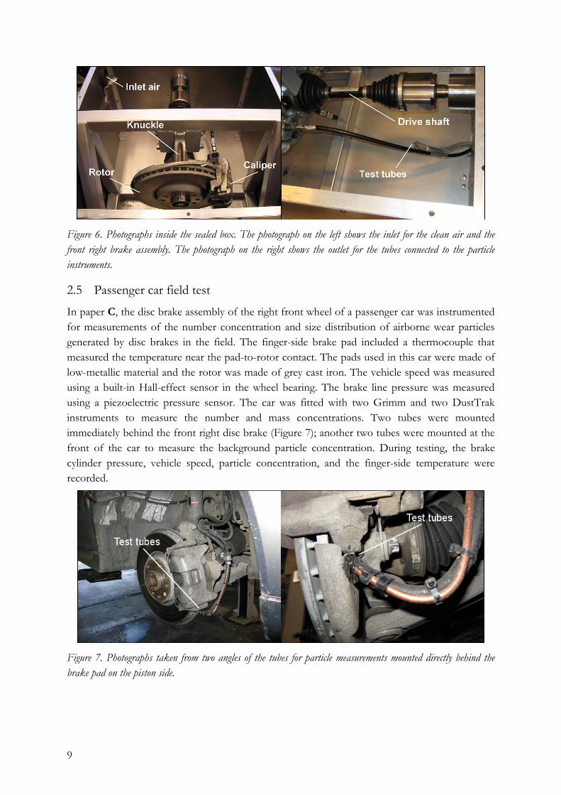
Figure 6. Photographs inside the sealed box. The photograph on the left shows the inlet for the clean air and the front right brake assembly. The photograph on the right shows the outlet for the tubes connected to the particle instruments.
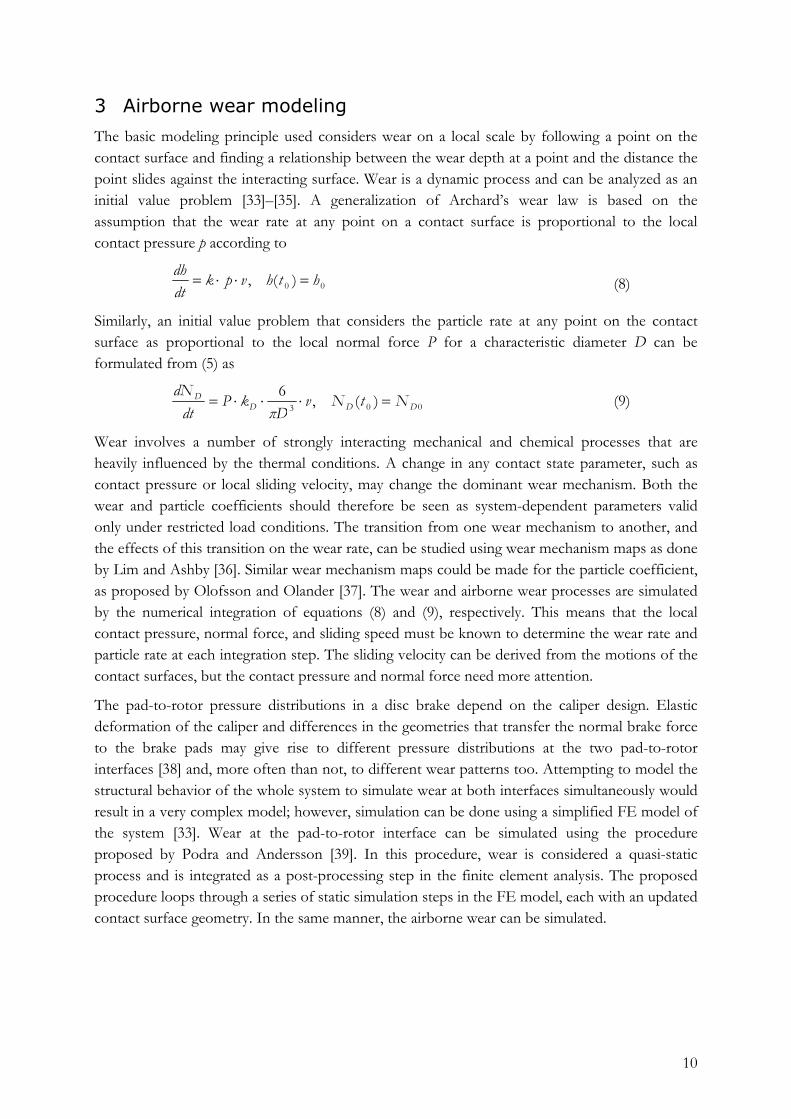
2.5 Passenger car field test In paper C, the disc brake assembly of the right front wheel of a passenger car was instrumented for measurements of the number concentration and size distribution of airborne wear particles generated by disc brakes in the field. The finger-side brake pad included a thermocouple that measured the temperature near the pad-to-rotor contact. The pads used in this car were made of low-metallic material and the rotor was made of grey cast iron. The vehicle speed was measured using a built-in Hall-effect sensor in the wheel bearing. The brake line pressure was measured using a piezoelectric pressure sensor. The car was fitted with two Grimm and two DustTrak instruments to measure the number and mass concentrations. Two tubes were mounted immediately behind the front right disc brake (Figure 7); another two tubes were mounted at the front of the car to measure the background particle concentration. During testing, the brake cylinder pressure, vehicle speed, particle concentration, and the finger-side temperature were recorded.
Figure 7. Photographs taken from two angles of the tubes for particle measurements mounted directly behind the brake pad on the piston side.
10
3 Airborne wear modeling
The basic modeling principle used considers wear on a local scale by following a point on the contact surface and finding a relationship between the wear depth at a point and the distance the point slides against the interacting surface. Wear is a dynamic process and can be analyzed as an initial value problem [33]–[35]. A generalization of Archard’s wear law is based on the assumption that the wear rate at any point on a contact surface is proportional to the local contact pressure p according to
00 )(, hthvpk
dtdh
=⋅⋅= (8)
Similarly, an initial value problem that considers the particle rate at any point on the contact surface as proportional to the local normal force P for a characteristic diameter D can be formulated from (5) as
003 )(,6DDD
D NtNvDπ
kPdt
dN=⋅⋅⋅= (9)
Wear involves a number of strongly interacting mechanical and chemical processes that are heavily influenced by the thermal conditions. A change in any contact state parameter, such as contact pressure or local sliding velocity, may change the dominant wear mechanism. Both the wear and particle coefficients should therefore be seen as system-dependent parameters valid only under restricted load conditions. The transition from one wear mechanism to another, and the effects of this transition on the wear rate, can be studied using wear mechanism maps as done by Lim and Ashby [36]. Similar wear mechanism maps could be made for the particle coefficient, as proposed by Olofsson and Olander [37]. The wear and airborne wear processes are simulated by the numerical integration of equations (8) and (9), respectively. This means that the local contact pressure, normal force, and sliding speed must be known to determine the wear rate and particle rate at each integration step. The sliding velocity can be derived from the motions of the contact surfaces, but the contact pressure and normal force need more attention.
The pad-to-rotor pressure distributions in a disc brake depend on the caliper design. Elastic deformation of the caliper and differences in the geometries that transfer the normal brake force to the brake pads may give rise to different pressure distributions at the two pad-to-rotor interfaces [38] and, more often than not, to different wear patterns too. Attempting to model the structural behavior of the whole system to simulate wear at both interfaces simultaneously would result in a very complex model; however, simulation can be done using a simplified FE model of the system [33]. Wear at the pad-to-rotor interface can be simulated using the procedure proposed by Podra and Andersson [39]. In this procedure, wear is considered a quasi-static process and is integrated as a post-processing step in the finite element analysis. The proposed procedure loops through a series of static simulation steps in the FE model, each with an updated contact surface geometry. In the same manner, the airborne wear can be simulated.
11
4 Summary of results of appended papers
This thesis comprises four appended papers (Appendices A–D) that discuss different aspects of airborne wear particles generated by disc brakes. A summary of the most important results for the two main topics of discussion are presented below.
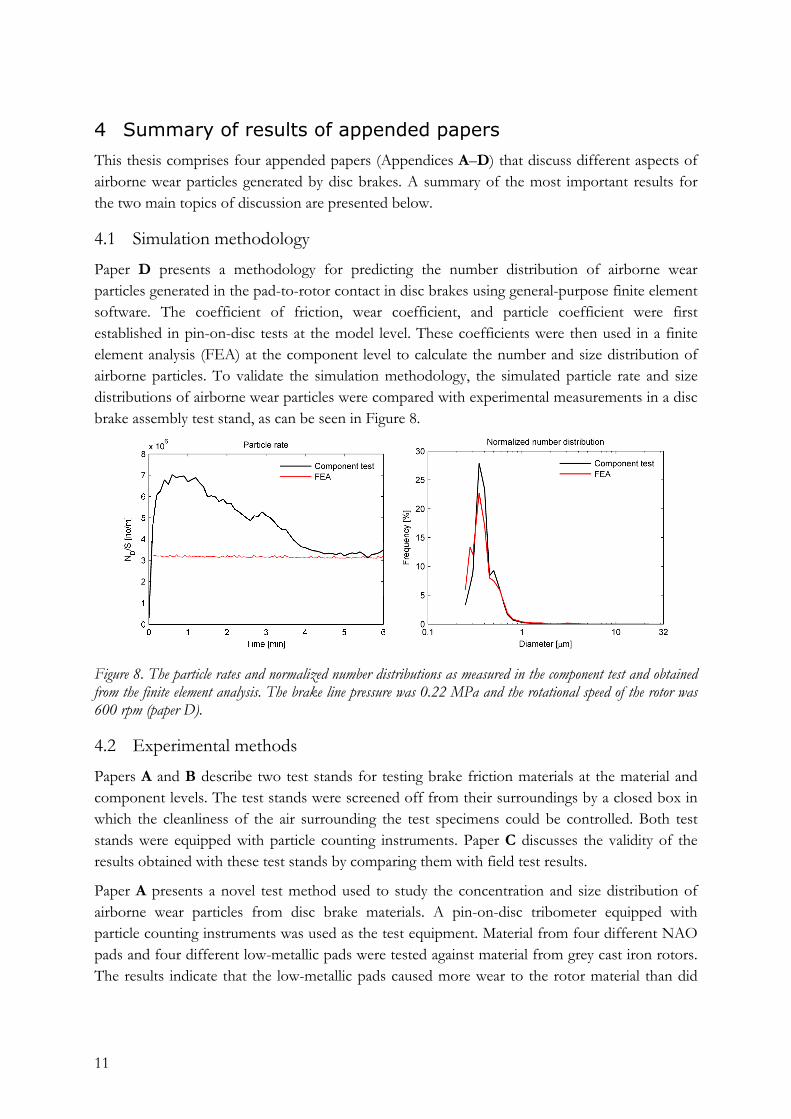
4.1 Simulation methodology Paper D presents a methodology for predicting the number distribution of airborne wear particles generated in the pad-to-rotor contact in disc brakes using general-purpose finite element software. The coefficient of friction, wear coefficient, and particle coefficient were first established in pin-on-disc tests at the model level. These coefficients were then used in a finite element analysis (FEA) at the component level to calculate the number and size distribution of airborne particles. To validate the simulation methodology, the simulated particle rate and size distributions of airborne wear particles were compared with experimental measurements in a disc brake assembly test stand, as can be seen in Figure 8.
Figure 8. The particle rates and normalized number distributions as measured in the component test and obtained from the finite element analysis. The brake line pressure was 0.22 MPa and the rotational speed of the rotor was 600 rpm (paper D).
4.2 Experimental methods Papers A and B describe two test stands for testing brake friction materials at the material and component levels. The test stands were screened off from their surroundings by a closed box in which the cleanliness of the air surrounding the test specimens could be controlled. Both test stands were equipped with particle counting instruments. Paper C discusses the validity of the results obtained with these test stands by comparing them with field test results.
Paper A presents a novel test method used to study the concentration and size distribution of airborne wear particles from disc brake materials. A pin-on-disc tribometer equipped with particle counting instruments was used as the test equipment. Material from four different NAO pads and four different low-metallic pads were tested against material from grey cast iron rotors. The results indicate that the low-metallic pads caused more wear to the rotor material than did
12
the NAO pads, resulting in higher concentrations of airborne wear particles. Although there were differences in the measured particle concentrations, similar size distributions were obtained.
Paper B presents a disc brake assembly test stand used to study the number concentration and size distribution of airborne wear particles from disc brake materials. The test stand consisted of a front right brake assembly mounted in a sealed chamber. A braking load was applied by a pneumatic system and the rotor was driven by an electric motor. The number and size of airborne wear particles was then measured. NAO-type and low-metallic brake pads were tested at low braking loads against material from grey cast iron rotors, which had been pre-conditioned with a rust layer to simulate a car standing parked overnight in a wet environment. The results suggest that this test stand can be used to study rust layer removal from the rotor.
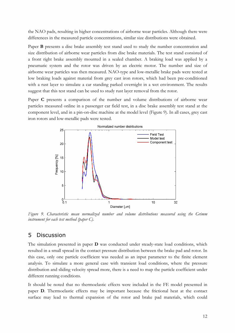
Paper C presents a comparison of the number and volume distributions of airborne wear particles measured online in a passenger car field test, in a disc brake assembly test stand at the component level, and in a pin-on-disc machine at the model level (Figure 9). In all cases, grey cast iron rotors and low-metallic pads were tested.
Figure 9. Characteristic mean normalized number and volume distributions measured using the Grimm instrument for each test method (paper C).
5 Discussion
The simulation presented in paper D was conducted under steady-state load conditions, which resulted in a small spread in the contact pressure distribution between the brake pad and rotor. In this case, only one particle coefficient was needed as an input parameter to the finite element analysis. To simulate a more general case with transient load conditions, where the pressure distribution and sliding velocity spread more, there is a need to map the particle coefficient under different running conditions.
It should be noted that no thermoelastic effects were included in the FE model presented in paper D. Thermoelastic effects may be important because the frictional heat at the contact surface may lead to thermal expansion of the rotor and brake pad materials, which could
13
significantly affect the behavior of the interface. Frictional heating also influences the oxidation rate on the contact surfaces, and thus indirectly the wear process. The use of finite element software gives the possibility of using coupled thermo-mechanical analysis to include the effects of frictional heating. A possible next step is to incorporate thermal effects in the FE model.
Test conditions varied due to the limitations of the test stands. It would be desirable to increase the rotational speed and/or radius of the disc specimens in the pin-on-disc machine presented in paper A, to better mimic urban driving conditions. In the disc brake assembly test stand presented in paper B, designed to allow the study of low cylinder pressure levels, it would be desirable to increase the applied load by using a stronger hydraulic motor. Both of the test stands run under stationary load conditions. It would be of interest to extend the capacity of the test stands to handle more realistic (transient) brake events. This could be done in the disc brake assembly test stand by controlling the pressure from the hydraulic system and the rotational speed of the motor. It is harder to control the pin-on-disc test stand, where dead weights are used to apply a load, though the rotational speed can be controlled. In addition, temperature measurements could be included in the pin-on-disc set-up by adding a thermocouple to all pin samples.
None of the particle instruments measures actual particle geometry. The volume calculations assume, perhaps erroneously, that the particles are spherical. To capture the size, shape, and material composition of the airborne wear particles, they could be pumped onto filters during testing in the test stands. Analysis of the filters could then be done using, for example, scanning electron microscopy (SEM) and energy dispersive x-ray spectroscopy (EDX). In addition, both the rotor and pads become worn during braking. The origin of the wear particles from either rotor or pads could be estimated by analyzing the SEM and EDX results. By enhancing our knowledge of the sizes, shapes, and composition of the wear particles, it may be possible to determine the dominant wear mechanism under different load conditions.
14
6 Conclusions
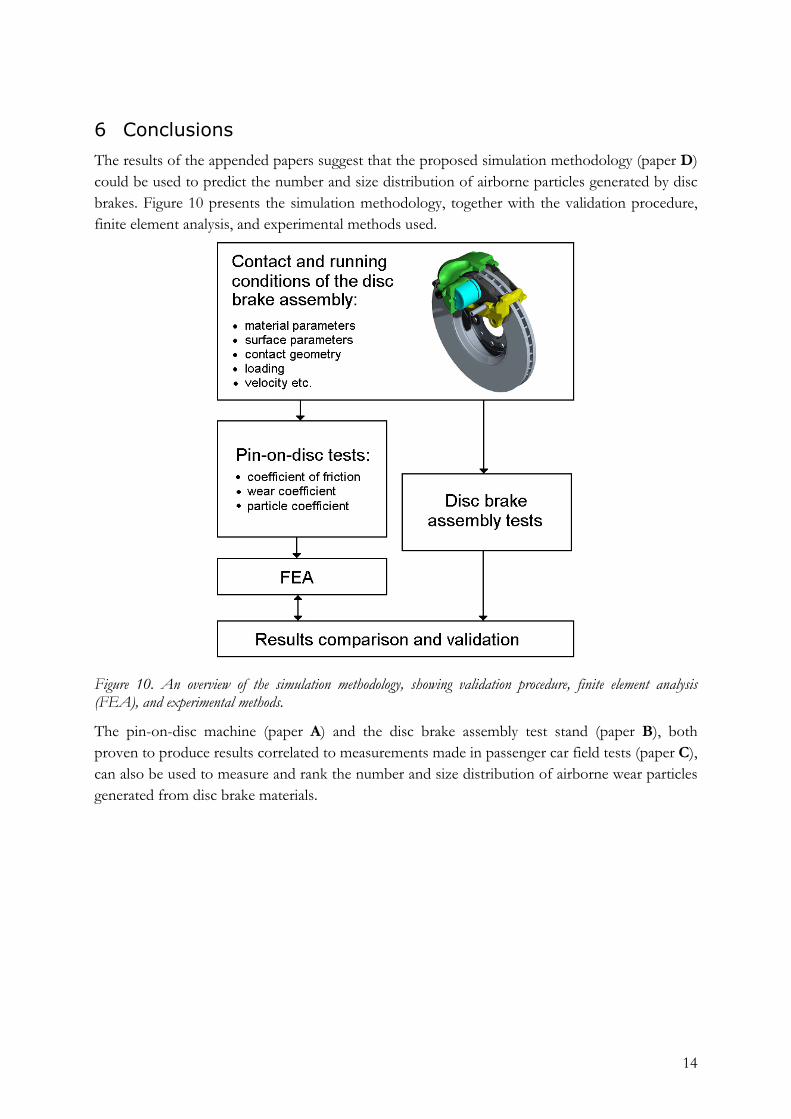
The results of the appended papers suggest that the proposed simulation methodology (paper D) could be used to predict the number and size distribution of airborne particles generated by disc brakes. Figure 10 presents the simulation methodology, together with the validation procedure, finite element analysis, and experimental methods used.
Figure 10. An overview of the simulation methodology, showing validation procedure, finite element analysis (FEA), and experimental methods.
The pin-on-disc machine (paper A) and the disc brake assembly test stand (paper B), both proven to produce results correlated to measurements made in passenger car field tests (paper C), can also be used to measure and rank the number and size distribution of airborne wear particles generated from disc brake materials.
15
7 References
[1] Chan D, Stachowiak G W. 2004. Review of automotive brake friction materials. Proceedings of the Institution of Mechanical Engineers. Part D: Journal of Automobile Engineering, 218(9), 953–966.
[2] Sanders P G, Xu N, Dalka T M, Maricq M. 2003. Airborne brake wear debris: size distributions, composition, and a comparison of dynamometer and vehicle tests. Environmental Science and Technology, 37(18), 4060–4069.
[3] Environmental Protection Agency (EPA). Particle size categories. http://www.epa.gov/apti/bces/module3/category/category.htm, 2009-06-13.
[4] Querol X, Alastuey A, Ruiz C R, Artiñano B, Hansson H C, Harrison R M, Buringh E, Ten Brink H M, Lutz M, Bruckmann P, Straeh P, Schneider J. 2004. Speciation and origin of PM10 and PM2.5 in selected European cities. Atmospheric Environment, 38(38), 6547–6555.
[5] Gehrig R, Hill M, Buchmann B. 2004. Separate determination of PM10 emission factors of road traffic for tailpipe emissions and emissions from abrasion and resuspension processes. International Journal of Environment and Pollution, 22(3), 312–325.
[6] Seaton A, Cherrie J, Dennekamp M, Donaldson K, Hurley J, Tran C. 2005. The London underground: dust and hazards to health. Occupational and Environmental Medicine, 62(6), 355–362.
[7] Branis M. 2006. The contributions of ambient sources to particle pollution in spaces and trains of the Prague underground transport system. Atmospheric Environment, 40(2), 348–356.
[8] Abu-Allaban M, Gillies J A, Gertler A W, Clayton R, Proffitt D. 2003. Tailpipe, resuspended road dust, and brake-wear emission factors from on-road vehicles. Atmospheric Environment, 37(37), 5283–5293.
[9] Weckwerth G. 2001. Verification of traffic-emitted aerosol components in the ambient air of Cologne (Germany). Atmospheric Environment, 35(32), 5525–5536.
[10] Katsouyanni K, Touloumi G, Samoli E, Gryparis A, Le Tertre A, Monopolis Y, Rossi G, Zmirou D. 2001. Confounding and effect modification in the short-term effects of ambient particles on total mortality: results from 29 European cities within the APHEA2 project. Epidemiology, 12(5), 521–531.
[11] Samet J M , Dominici F, Curriero F C, Coursac I, Zeger S L. 2000. Fine particulate air pollution and mortality in 20 U.S. cities, 1987–1994. New England Journal of Medicine, 343(24), 1742–1749.
[12] Pope C A, Burnett R T, Thun M J, Calle E E, Krewski D, Ito K, Thurston G D. 2002. Lung cancer, cardiopulmonary mortality, and long-term exposure to fine particulate air pollution. The Journal of the American Medical Assocation, 287 (9), 1132–1141.
16
[13] European Commission (EC). Air quality standards. http://ec.europa.eu/environment /air/quality/standards.htm, 2009-05-30.
[14] Environmental Protection Agency (EPA). National ambient air quality standards (NAAQS). http://earth1.epa.gov/air/criteria.html, 2009-05-30.
[15] City of Stockholm. Facts about the environment in Stockholm, Sweden. http://miljobarometern.stockholm.se/sub.asp?mp=TEMA&mo=2&dm=2, 2009-06-17.
[16] Hjortenkrans D, Bergbäck B, Häggerud A. 2007. Metal emissions from brake linings and tires: case studies of Stockholm, Sweden 1995/1998 and 2005. Environmental Science and Technology, 41(15), 5224–5230.
[17] Iijima A, Sato K, Yano K, Kato M, Kozawa K, Furuta N. 2008. Emission factor for antimony in brake abrasion dust as one of the major atmospheric antimony sources. Environmental Science and Technology,42(8): 2937–2942.
[18] Furusjö E, Sternbeck J, Palm A, Cousins I. 2007. PM10 source characterization at urban and highway roadside locations. Science of the Total Environment, 387(1–3), 206–219.
[19] Riediker M, Gasser M, Perrenoud A, Gehr P, Rothen-Rutishauser B. 2008. A system to test the toxicity of brake wear particles. 12th International ETH-Conference on Combustion Generated Nanoparticles, 23–25 June 2008, Zurich, Switzerland.
[20] Olofsson U, Olander L, Jansson A. 2009. Towards a model for the number of airborne particles generated from a sliding contact. Journal of Wear. In press.
[21] Archard J F. Contact and rubbing of flat surfaces. 1953. Journal of Applied Physics, 24 (8), 981–988.
[22] Holm R. 1946. Electric Contacts. Almqvist & Wiksells, Uppsala, Sweden.
[23] Blau P J, Meyer III H M. 2003. Characteristics of wear particles produced during friction tests of conventional and unconventional disc brakes materials. Wear, 255(7–12), 1261–1269.
[24] Österle W, Kloss H, Urbon I, Dmitriev A I. 2006. Towards a better understanding of friction brake materials. Wear, 263 (7–12), 1189–1201.
[25] Blau P J, Truhan Jr. J J, Kenik E A. 2007. Effects of the exposure to corrosive salts on the frictional behavior of gray cast iron and a titanium-based metal matrix composite. Tribology International, 40 (9), 1335–1343.
[26] Garg D G, Cadle S H, Mulawa P A, Groblicki P J. 2000. Brake wear particle matter emission. Environmental Science and Technology, 43(21), 4463–4469.
[27] Peters T M, Ott D, O’Shaughnessy P T. 2006. Comparison of the Grimm 1.108 and 1.109 portable aerosol spectrometer to the TSI 3321 aerodynamic particle sizer for dry particles. Annals of Occupational Hygiene, 50(8), 843–850.
[28] Liu Y, Daum P H. 2000. The effect of refractive index on size distributions and light scattering coefficients derived from optical particle counters. Journal of Aerosol Science, 31(8), 945–957.
17
[29] Zhu Y, Yu N, Kuhn T, Hinds W. 2006. Field comparison of P-Trak and condensation particle counters. Aerosol Science and Technology, 40(6), 422–430.
[30] Cheng Y H. 2008. Comparison of the TSI Model 8520 and Grimm Series 1.108 portable aerosol instruments used to monitor particulate matter in an iron foundry. Journal of Occupational and Environmental Hygiene, 5(3), 157–168.
[31] Knutson EO, Whitby K T. 1975. Aerosol classification by electric mobility: apparatus theory and applications. Journal of Aerosol Science, 6(6), 443–451.
[32] Olofsson U, Olander L, Jansson A. A study of airborne wear particles generated from a sliding contact. Journal of Tribology. In Press.
[33] Söderberg A, Sellgren U, Andersson S. 2008. Using finite element analysis to predict the brake pressure needed for effective rotor cleaning in disc brakes. Document 2008-01-2565. 26th SAE Brake Colloquium and Exhibition, October 2008, San Antonio, TX.
[34] Hugnell A, Björklund S, Andersson S. 1996. Simulation of mild wear in a cam-follower contact with follower rotation. Wear, 199(2), 202–210.
[35] Flodin A, Andersson S. 1999. Wear simulation of spur gears. TriboTest Journal, 5(3), 225–249.
[36] Lim S C, Ashby M F. 1987. Wear-mechanism maps. Acta metal, 35, 1–24.
[37] Olofsson U, Olander L. 2008. On the identification of wear modes and transitions using airborne wear particles generated from sliding steel-on-steel contact. Submitted to Wear.
[38] Antanaitis D, Sanford J. 2006. The effect of racetrack/high energy driving on brake caliper performance. Document number 2006-01-0472. SAE 2006 World Congress & Exhibition, April 2006, Detroit, MI.
[39] Podra P, Andersson S. 1999. Simulating sliding wear with finite element method. Tribology International, 32(2), 71–81.


![[2014] Towards Lattice-Boltzmann Prediction of Turbofan.pdf](https://img.pdfslide.net/doc/110x75/577cc3f81a28aba71197bc9f/2014-towards-lattice-boltzmann-prediction-of-turbofanpdf.jpg)