Embed Size (px)
Citation preview
Towards Long-endurance Flight: Design and Implementation of aVariable-pitch Gasoline-engine Quadrotor
Tao Pang1, Kemao Peng1, Feng Lin1 and Ben M. Chen2
Abstract— Majority of today’s fixed-pitch, electric-powerquadrotors have short flight endurance (< 1 hour) which greatlylimits their applications. This paper presents a design method-ology for the construction of a long-endurance quadrotor usingvariable-pitch rotors and a gasoline-engine. The methodologyconsists of three aspects. Firstly, the rotor blades and gasolineengine are selected as a pair, so that sufficient lift can becomfortably provided by the engine. Secondly, drivetrain andairframe are designed. Major challenges include airframe vi-bration minimization and power transmission from one engineto four rotors while keeping alternate rotors contra-rotating.Lastly, a PD controller is tuned to facilitate preliminary flighttests. The methodology has been verified by the constructionand successful flight of our gasoline quadrotor prototype, whichis designed to have a flight time of 2 to 3 hours and a maximumtake-off weight of 10 kg.
I. INTRODUCTION
Primarily due to their mechanical simplicity, quadrotorunmanned aerial vehicles (UAVs) have become a popularplatform for research and civilian activities in recent years.Various research groups have used quadrotor UAVs to imple-ment algorithms in many research areas, such as vision/laserbased navigation and simultaneous localization and mapping(SLAM). On the other hand, quadrotors carrying digitalcameras are also widely used in aerial photography, powerline inspection and many other situations.
Quadrotors today are almost exclusively battery-powered,and consist of four electric motors, each of which directlydrives a fixed-pitch propeller. Accordingly, the motion of thequadrotor is controlled by differential motor speed. Whilethis simple configuration is the reason behind quadrotorsmechanical simplicity, it is also the reason for one of quadro-tors major drawbacks: limited flight endurance. According totechnical specifications provided by major quadrotor manu-facturers, flight endurance of most quadrotors today rangesfrom 20 minutes to an hour, which greatly limits theirpractical applications.
It is possible, however, to increase the flight enduranceof quadrotors to a few hours by using a gasoline engine,and employing an appropriate drivetrain to transmit powerfrom the engine to the rotors. However, control actions canno longer be generated by differential rotor speed becauseall rotors, which are mechanically linked by the drivetrain,rotate at the same speed. In order to generate the necessarycontrol actions, variable-pitch propellers have to be used,
1Tao Pang, Kemao Peng and Feng Lin are with the TemasekLaboratories, NUS, Singapore. [email protected],[email protected], [email protected]
2Ben M. Chen is with the Department of Electrical & Computer Engi-neering, NUS, Singapore. [email protected]
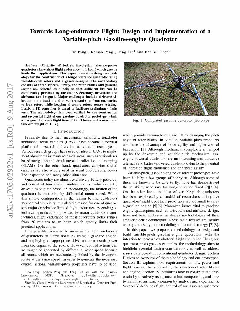
Fig. 1: Completed gasoline quadrotor prototype
which provide varying torque and lift by changing the pitchangle of rotor blades. In addition, variable-pitch propellersalso have the advantage of better agility and higher controlbandwidth [1]. Although mechanical complexity is rampedup by the drivetrain and variable-pitch mechanism, gas-engine-powered quadrotors are an interesting and attractivealternative to battery-powered quadrotors, due to the potentialof increased flight endurance and enhanced agility.
Variable-pitch, gasoline-engine quadrotor prototypes havebeen built by a few groups of hobbyists. Although some ofthem are known to be able to fly, none has demonstratedthe reliability necessary for long-endurance flight [2][3][4].On the other hand, the idea of variable-pitch quadrotorshas been explored by a handful of researchers to improvequadrotors’ agility, but their prototypes are too small to carrya gasoline engine [5][6]. Moreover, issues vital to gasolineengine quadcopters, such as drivetrain and airframe design,have not been addressed in design methodologies of theirsmaller electric counterpart, whose main focuses are usuallyaerodynamics, dynamic modeling and control strategy [7][8].
In this paper, we propose a methodology to design andbuild variable-pitch gasoline-engine quadrotors, with theintention to increase quadrotors’ flight endurance. Using ourquadrotor prototypes as examples, the methodology aims tohighlight essential design considerations as well as addressissues overlooked in conventional quadrotor design. SectionII gives an overview of the methodology and our prototypes.Section III explains how requirements on lift, power andflight time can be achieved by the selection of rotor bladesand engine. Section IV introduces how to construct the driv-etrain by creatively using mechanical components, and howto minimize airframe vibration by analysis and experiments.Section V describes flight control of our gasoline quadrotor
arX
iv:1
708.
0292
2v1
[cs
.RO
] 9
Aug
201
7

prototypes. Section VI shows flight test results and SectionVII discusses conclusions and future works.
II. DESIGN OVERVIEW
Our gasoline quadrotor (Figure 1) resembles conventionalX-shape quadrotors. The rotors are located at the tips ofthe “X” with the engine, avionics, batteries, fuel tank andadditional sensors stacked at the center.
Fig. 2: Gasoline quadrotor dimensions (mm)
The first step in the design of the gas-engine quadrotorwas to determine the size of the rotors and the engine, whichdetermined its size and weight. The drivetrain and airframewere then designed accordingly. Finally, the quadrotor waswired up to a commercial autopilot named Pixhawk. A PDcontroller was used for attitude control, whose gains can betuned during flight tests.
It is well known that compared with electric motors,gasoline engines require a more complicated drivetrain andinduce more vibration to the airframe. Therefore, a proof-of-concept prototype powered by an electric motor was firstbuilt to verify key aspects of the design methodology beforetackling the additional complication of gasoline engines.After the electric prototype proved to be successful, weproceeded with the conversion from electricity to gasoline,which mainly involved the addition of a clutch mechanismand reinforcement of the airframe. A schematic diagram ofthis design and testing process is shown in Figure 3.
Fig. 3: Design flowchart
Powered by a 1.8 kW engine, the gasoline quadrotor hasa maximum thrust of 16 kg, a maximum take-off weight of10kg and an empty weight of 6.5 kg. Dimensions of the
gasoline prototype is shown in Figure 2. Having the samepropulsion capacity and dimensions as the gasoline quadro-tor, the electric prototype uses a motor with a maximumoutput of 2 kW powered by 22.2 V 6s Li-po batteries.
III. SELECTION OF ROTOR AND ENGINE
As customization of rotor blade and engine can be com-plicated and time-consuming [8][9], off-the-shelf hobby he-licopter components are used for the implementation of ourprototypes. A survey of hobby gas engines and rotor bladesreveals that the Zenoah gas engine series with an outputfrom 1.5 to 2.5 kW is mature, reliable and widely used forsmall-scale gasoline helicopters. On the other hand, hobbyhelicopter main rotor blades whose diameters range from 0.3to 1.8 m can serve as the blades for our gasoline quadrotor.
The final rotor and engine combination depends on howmuch power is consumed by a rotor of a certian size, whichcan be estimated using momentum theory and blade elementtheory. For a single rotor, momentum theory estimates theminimum power required to generate a certain lift N , whichis given by
P =N
32
√2ρA
(1)
where P is the total power, N is the total lift, ρ is the densityof air and A is the rotor area [10]. If we consider a multirotorgenerating a total lift N with n rotors, each having a diskarea Am, the total power consumed by the multirotor is givenby
Pm = n
(Nn
) 32
√2ρAm
=N
32√
2ρ(nAm)(2)
It can be seen that for a given lift, the total powerconsumed by a multirotor is inversely proportional to thesquare root of the total rotor area, nAm. The conclusiongiven by momentum theory, therefore, is that power per unitlift can be minimized by maximizing total rotor area.
The relationship between lift, power and the pitch angle ofthe rotor can be further deduced from blade element theory.The lift and power coefficients are defined respectively as
CT = T/ρA(ΩR)2 (3)
CP = P/ρA(ΩR)3 (4)
where Ω and R are the angular velocity and radius of therotor respectively, and A is the rotor disk area [10].
It can be shown that
CT =σa
2
(θ
3− λ
2
)(5)
λ =σa
16
[√1 +
64
σaθ − 1
](6)
where λ is called the inflow ratio, σ is the rotor solidity ratiodefined as the ratio of the rotor surface area over the rotor

disk area, Cl = aα where Cl is the sectional lift coefficientand α is the angle of attack [10].
The power coefficient CP is given by
CP = CPi+ CPo
(7)
CPi= κ
CT32
√2
(8)
CPo =σ
8
(β0 + β1α+ β2α
2)
(9)
where CPistands for induced power (to generate lift) with
κ being the empirical induced power correction factor, andCPo for profile power (to counter drag) with β1, β2 and β3being empirical coefficients [10]. Values of the aerodynamicconstants are shown in Table I.
TABLE I: Aerodynamic constants
a κ β0 β1 β2 ρ5.7 1.60 0.0130 -0.0216 0.400 1.18kg/m3
Lift, drag and power consumption for rotor blades ofdifferent sizes can thus be calculated using equation 3 to 9.After examining several hobby rotor blades, it has been foundthat the 800 mm diameter rotor blades used for 450 classhobby helicopters generate sufficient lift while consuminga reasonable amount of power. 800 mm is also the largestrotor diameter the airframe can accommodate given otherdesign constraints. Using the aforementioned equations, therelationship between pitch angle and lift, power and torque at2500 revolution per minute (RPM), the operating RPM rec-ommended by blade manufacturer, is calculated and shownin Figure 5a and 5b.
Fig. 4: Single rotor lift and torque test stand
The results from theoretical calculations were furthercorroborated by experiments. A test stand consisting of aload cell, an optical RPM sensor and the same variable-pitch mechanism used on the gasoline quadrotor was built tomeasure the thrust, torque and rotational speed of the rotor atdifferent pitch angles (Figure 4). As shown in Figure 5a and5b, the measured torque and lift (shown as asterisks) agreewell with the theoretical results.
The maximum lift, maximum take-off weight and enginehorsepower can thus be determined using the results above.The operating range of pitch angle for the 800mm rotor isbetween ±14. As seen in Figure 5a, the lift generated byone rotor is 39 N, or 4.0 kg when pitch angle is equal to 14,giving a total maximum lift of 16 kg. Using a 50% controlmargin, the maximum take-off weight of the quadrotor canbe as much as 10 kg. It is also observed in Figure 5b thatthe total power and torque at maximum pitch are 1.3 kWand 5.2 Nm respectively. Based on the power and torquerequirements, the Zenoah 270RC single cylinder gasolineengine with a displacement of 25.4 cc is chosen. Detailedtorque and power curves of the engine can be found in [11].With proper gearing, the engine is able to provide sufficientpower and torque for the gasoline power quadrotor.
0 5 10 150
10
20
30
40
50
60
Lift
(N)
pitch angle (degree)
CalculationExperiment
(a) Lift vs. pitch angle
0 5 10 150
100
200
300
400
500
600
700
Pow
er (
W)
pitch angle (degree)
CalculationExperiment
0 5 10 150
0.5
1
1.5
2
2.5
Tor
que
(N.m
)
pitch angle (degree)
CalculationExperiment
(b) Power and torque vs. pitch angle
Fig. 5: Lift, Power and torque of 800 mm rotor at 2500 RPM
Flight endurance can also be estimated using Figure 5. Itis known that the empty weight of the gasoline quadrotor is6.5 kg (Section II), and that fuel consumption for ZenoahRC series engine is 554 g/kWh [11]. At maximum take-off
weight (10 kg), the pitch angle required to take off is 8
with the quadrotor consuming 1.0 kW in total. Assumingthat 2.5 L of gasoline is carried on-board and a transmissionefficiency of 80%, the flight time can be roughly estimatedas
2.5L× 770g/L
554g/kWh×(1kW/0.8)= 2.8 hours (10)
IV. DRIVETRAIN AND AIRFRAME DESIGN
A. Drivetrain
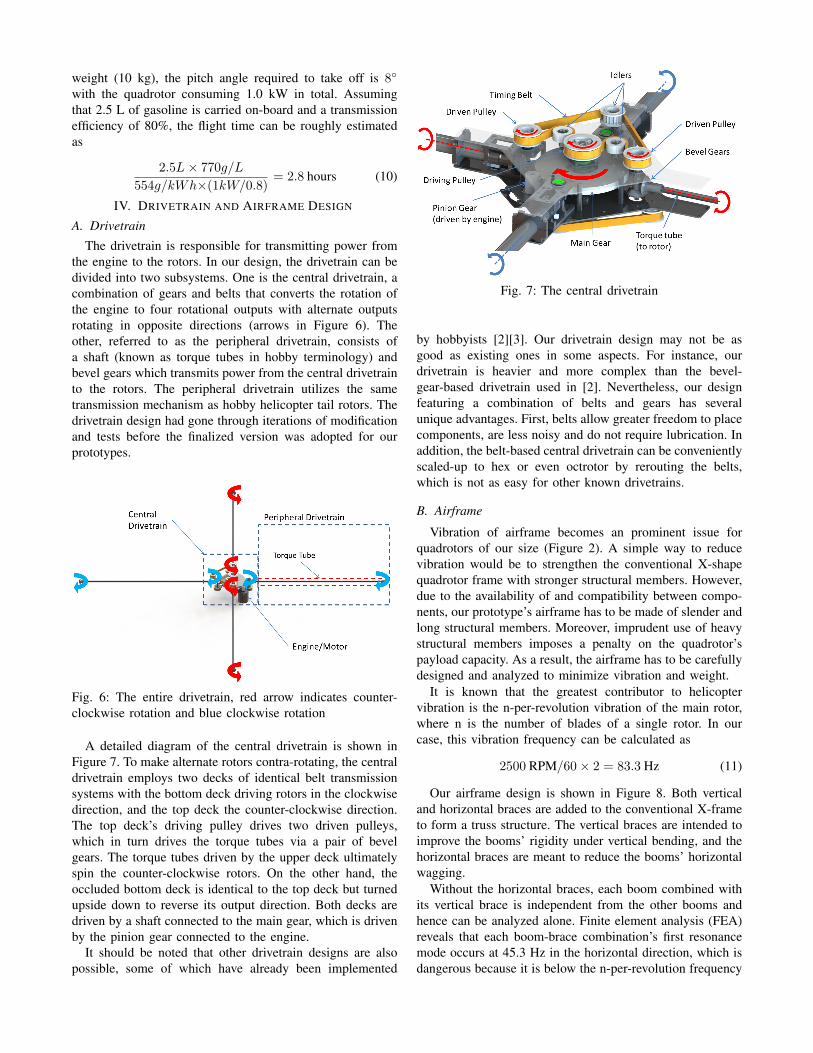
The drivetrain is responsible for transmitting power fromthe engine to the rotors. In our design, the drivetrain can bedivided into two subsystems. One is the central drivetrain, acombination of gears and belts that converts the rotation ofthe engine to four rotational outputs with alternate outputsrotating in opposite directions (arrows in Figure 6). Theother, referred to as the peripheral drivetrain, consists ofa shaft (known as torque tubes in hobby terminology) andbevel gears which transmits power from the central drivetrainto the rotors. The peripheral drivetrain utilizes the sametransmission mechanism as hobby helicopter tail rotors. Thedrivetrain design had gone through iterations of modificationand tests before the finalized version was adopted for ourprototypes.
Fig. 6: The entire drivetrain, red arrow indicates counter-clockwise rotation and blue clockwise rotation
A detailed diagram of the central drivetrain is shown inFigure 7. To make alternate rotors contra-rotating, the centraldrivetrain employs two decks of identical belt transmissionsystems with the bottom deck driving rotors in the clockwisedirection, and the top deck the counter-clockwise direction.The top deck’s driving pulley drives two driven pulleys,which in turn drives the torque tubes via a pair of bevelgears. The torque tubes driven by the upper deck ultimatelyspin the counter-clockwise rotors. On the other hand, theoccluded bottom deck is identical to the top deck but turnedupside down to reverse its output direction. Both decks aredriven by a shaft connected to the main gear, which is drivenby the pinion gear connected to the engine.
It should be noted that other drivetrain designs are alsopossible, some of which have already been implemented
Fig. 7: The central drivetrain
by hobbyists [2][3]. Our drivetrain design may not be asgood as existing ones in some aspects. For instance, ourdrivetrain is heavier and more complex than the bevel-gear-based drivetrain used in [2]. Nevertheless, our designfeaturing a combination of belts and gears has severalunique advantages. First, belts allow greater freedom to placecomponents, are less noisy and do not require lubrication. Inaddition, the belt-based central drivetrain can be convenientlyscaled-up to hex or even octrotor by rerouting the belts,which is not as easy for other known drivetrains.
B. Airframe
Vibration of airframe becomes an prominent issue forquadrotors of our size (Figure 2). A simple way to reducevibration would be to strengthen the conventional X-shapequadrotor frame with stronger structural members. However,due to the availability of and compatibility between compo-nents, our prototype’s airframe has to be made of slender andlong structural members. Moreover, imprudent use of heavystructural members imposes a penalty on the quadrotor’spayload capacity. As a result, the airframe has to be carefullydesigned and analyzed to minimize vibration and weight.
It is known that the greatest contributor to helicoptervibration is the n-per-revolution vibration of the main rotor,where n is the number of blades of a single rotor. In ourcase, this vibration frequency can be calculated as
2500 RPM/60× 2 = 83.3 Hz (11)
Our airframe design is shown in Figure 8. Both verticaland horizontal braces are added to the conventional X-frameto form a truss structure. The vertical braces are intended toimprove the booms’ rigidity under vertical bending, and thehorizontal braces are meant to reduce the booms’ horizontalwagging.
Without the horizontal braces, each boom combined withits vertical brace is independent from the other booms andhence can be analyzed alone. Finite element analysis (FEA)reveals that each boom-brace combination’s first resonancemode occurs at 45.3 Hz in the horizontal direction, which isdangerous because it is below the n-per-revolution frequency
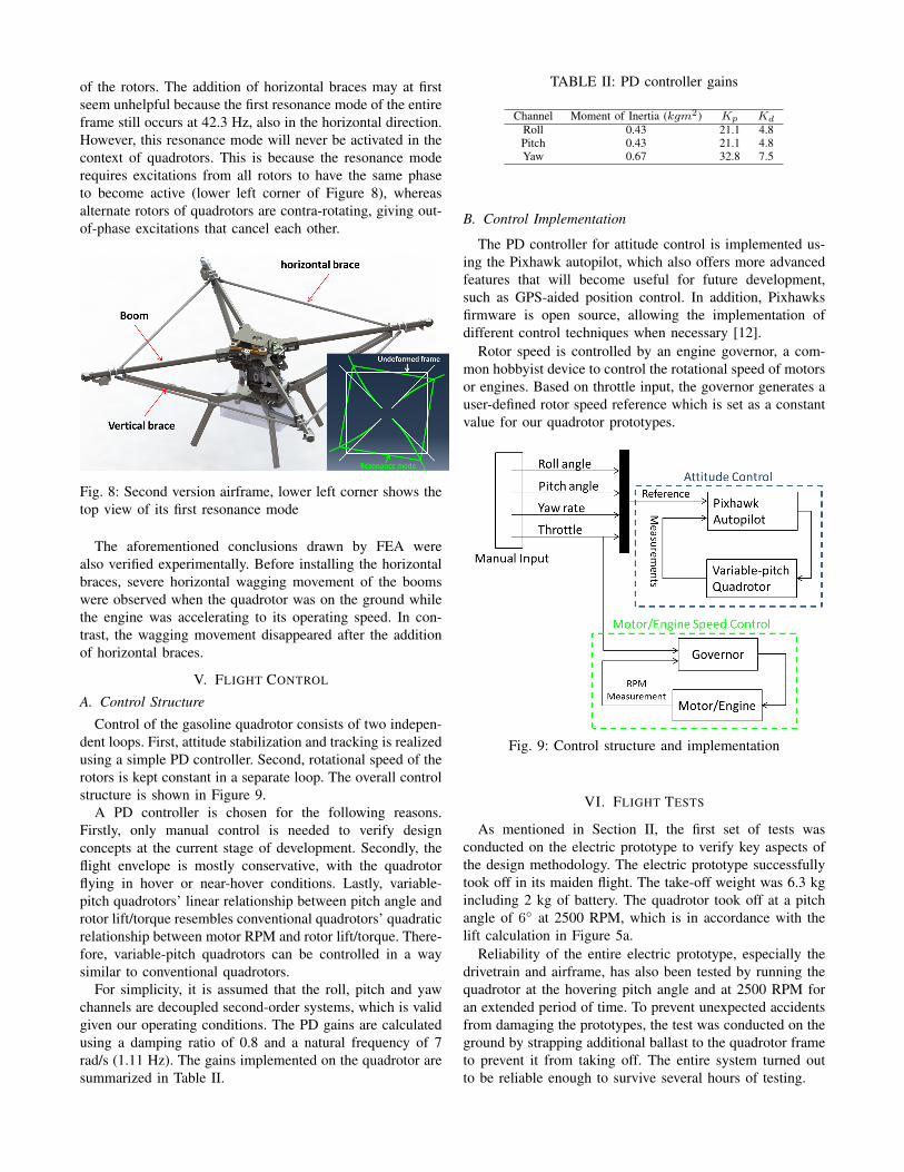
of the rotors. The addition of horizontal braces may at firstseem unhelpful because the first resonance mode of the entireframe still occurs at 42.3 Hz, also in the horizontal direction.However, this resonance mode will never be activated in thecontext of quadrotors. This is because the resonance moderequires excitations from all rotors to have the same phaseto become active (lower left corner of Figure 8), whereasalternate rotors of quadrotors are contra-rotating, giving out-of-phase excitations that cancel each other.
Fig. 8: Second version airframe, lower left corner shows thetop view of its first resonance mode
The aforementioned conclusions drawn by FEA werealso verified experimentally. Before installing the horizontalbraces, severe horizontal wagging movement of the boomswere observed when the quadrotor was on the ground whilethe engine was accelerating to its operating speed. In con-trast, the wagging movement disappeared after the additionof horizontal braces.
V. FLIGHT CONTROL
A. Control Structure
Control of the gasoline quadrotor consists of two indepen-dent loops. First, attitude stabilization and tracking is realizedusing a simple PD controller. Second, rotational speed of therotors is kept constant in a separate loop. The overall controlstructure is shown in Figure 9.
A PD controller is chosen for the following reasons.Firstly, only manual control is needed to verify designconcepts at the current stage of development. Secondly, theflight envelope is mostly conservative, with the quadrotorflying in hover or near-hover conditions. Lastly, variable-pitch quadrotors’ linear relationship between pitch angle androtor lift/torque resembles conventional quadrotors’ quadraticrelationship between motor RPM and rotor lift/torque. There-fore, variable-pitch quadrotors can be controlled in a waysimilar to conventional quadrotors.
For simplicity, it is assumed that the roll, pitch and yawchannels are decoupled second-order systems, which is validgiven our operating conditions. The PD gains are calculatedusing a damping ratio of 0.8 and a natural frequency of 7rad/s (1.11 Hz). The gains implemented on the quadrotor aresummarized in Table II.
TABLE II: PD controller gains
Channel Moment of Inertia (kgm2) Kp Kd
Roll 0.43 21.1 4.8Pitch 0.43 21.1 4.8Yaw 0.67 32.8 7.5
B. Control Implementation
The PD controller for attitude control is implemented us-ing the Pixhawk autopilot, which also offers more advancedfeatures that will become useful for future development,such as GPS-aided position control. In addition, Pixhawksfirmware is open source, allowing the implementation ofdifferent control techniques when necessary [12].
Rotor speed is controlled by an engine governor, a com-mon hobbyist device to control the rotational speed of motorsor engines. Based on throttle input, the governor generates auser-defined rotor speed reference which is set as a constantvalue for our quadrotor prototypes.
Fig. 9: Control structure and implementation
VI. FLIGHT TESTS
As mentioned in Section II, the first set of tests wasconducted on the electric prototype to verify key aspects ofthe design methodology. The electric prototype successfullytook off in its maiden flight. The take-off weight was 6.3 kgincluding 2 kg of battery. The quadrotor took off at a pitchangle of 6 at 2500 RPM, which is in accordance with thelift calculation in Figure 5a.
Reliability of the entire electric prototype, especially thedrivetrain and airframe, has also been tested by running thequadrotor at the hovering pitch angle and at 2500 RPM foran extended period of time. To prevent unexpected accidentsfrom damaging the prototypes, the test was conducted on theground by strapping additional ballast to the quadrotor frameto prevent it from taking off. The entire system turned outto be reliable enough to survive several hours of testing.

Fig. 10: Gasoline quadrotor in flight
The gasoline prototype has also successfully taken off andhovered for a few minutes with manual control (Figure 10).The roll, pitch and yaw angles were able to follow the refer-ence input provided by the human pilot, as shown in Figure11. However, the designed endurance was not experimentallyverified due to various problems manifested during the test.For instance, the operating RPM was lowered during the testbecause vibration was still too severe. Additional tests andimprovements are necessary to achieve long-endurance flight.
0 2 4 6 8 10 12−5
0
5
time (s)
Rol
l ang
le (
degr
ees)
MeasurementReference
0 2 4 6 8 10 12−5
0
5
10
time (s)
Pitc
h an
gle
(deg
rees
)
MeasurementReference
0 2 4 6 8 10 1260
65
70
75
time (s)
Hea
ding
ang
le (
degr
ees)
MeasurementReference
Fig. 11: Flight data samples of gasoline engine quadrotor
VII. CONCLUSION AND FUTURE WORK
Illustrated by our prototypes, a methodology to designand construct variable-pitch long-endurance gasoline-enginequadrotors has been presented. The methodology is com-prised of three steps. Firstly, rotor and engine sizes aredetermined using experimentally-validated results from aero-dynamics. The second step is to design and build a reliabledrivetrain and airframe. A drivetrain with alternate rotorscontra-rotating was creatively realized using a combinationof timing belts and gears. On the other hand, vibrationturned out to be a prominent concern in airframe design,
but can be mitigated with the help of FEA. Lastly, attitudeand rotor speed control are implemented respectively usingPixhawk autopilot and engine governor. The methodologywas first verified by the successful flight of the proof-of-concept electric quadrotor prototype. The gasoline prototypehas also been designed, built and flown with manual control.
The prototypes have a designed maximum thrust of 16 kgand a maximum take-off weight of 10 kg. Expected flightendurance of the gasoline prototype is 2.8 hours.
We will continue to test and improve the gasoline proto-type to achieve its designed flight endurance. The drivetrainand airframe will also be further optimized to make thequadrotor lighter, more efficient and more reliable. Moreadvanced control techniques could also be implemented tofully utilize the variable-pitch rotors. Moreover, once the2.8 hour flight endurance is proven, it will greatly expandquadrotors’ applications and open up new problems andchallenges.
ACKNOWLEDGMENT
The authors would like to thank Mr. Duojiing Goh, Mr.Joe Hwee and Mr. Kangli Wang for their advice and supportduring the development and testing of the long-endurancequadrotor prototypes.
REFERENCES
[1] M. Cutler, N. K. Ure, B. Michini, and J. P. How, “Comparison of fixedand variable pitch actuators for agile quadrotors,” in AIAA Guidance,Navigation, and Control Conference (GNC), Portland, OR, 2011.
[2] S. V. Natter, “Gas powered single engine variable pitch quadcopter,”http://diydrones.com/profiles/blogs/gas-powered-single-engine-variable-pitch-quadcopter, May 2014.
[3] R. Navoni, “Hg3 the era of quad variable pitch has begun!”http://www.virtualrobotix.com/profiles/blogs/hg3-the-era-of-quad-variable, August 2010.
[4] CJ Youngblood Enterprises Inc, “Stingray 500,”http://curtisyoungblood.com/V2/products/quadcopters/stingray-500,May 2015.
[5] K. Kawasaki, M. Zhao, K. Okada, and M. Inaba, “Muwa: Multi-field universal wheel for air-land vehicle with quad variable-pitch pro-pellers,” in IEEE/RSJ International Conference on Intelligent Robotsand Systems (IROS), 2013, pp. 1880–1885.
[6] B. Michini, J. Redding, N. K. Ure, M. Cutler, and J. P. How, “Designand flight testing of an autonomous variable-pitch quadrotor,” in IEEEInternational Conference on Robotics and Automation (ICRA), 2011,pp. 2978–2979.
[7] G. M. Hoffmann, H. Huang, S. L. Waslander, and C. J. Tomlin,“Quadrotor helicopter flight dynamics and control: Theory and ex-periment,” in Proc. of the AIAA Guidance, Navigation, and ControlConference, vol. 2, 2007.
[8] P. Pounds and R. Mahony, “Design principles of large quadrotors forpractical applications,” in IEEE International Conference on Roboticsand Automation (ICRA), 2009, pp. 3265–3270.
[9] P. Pounds, R. Mahony, J. Gresham, P. Corke, and J. M. Roberts, “To-wards dynamically-favourable quad-rotor aerial robots,” in Proceed-ings of the 2004 Australasian Conference on Robotics & Automation,2004.
[10] W. Johnson, Helicopter theory. Courier Corporation, 2012.[11] Husqvarna Zenoah Co., Ltd., “Zenoah 270rc product page,”
http://www.zenoah.co.jp/int/products/hobby-engines/g270rc/, May2015.
[12] 3DRobotics Inc., “3dr pixhawk product page,”https://store.3drobotics.com/products/3dr-pixhawk, May 2015.