Embed Size (px)
DESCRIPTION
5
Citation preview
International Journal of Thermal Sciences 47 (2008) 942–953www.elsevier.com/locate/ijts
Optimizing condenser fan control for air-cooled centrifugal chillers
F.W. Yu ∗, K.T. Chan
Department of Building Services Engineering, The Hong Kong Polytechnic University, Hung Hom, Hong Kong, China
Received 1 February 2007; received in revised form 30 July 2007; accepted 30 July 2007
Available online 29 August 2007
Abstract
The current design and operation of air-cooled condensers can cause a significant decrease in chiller performance under part load conditions.This paper demonstrates optimal condenser fan control to improve the coefficient of performance (COP) of air-cooled chillers. This controlinvolves identifying the optimum set point of condensing temperature with the optimized power relationships of the compressors and condenserfans and enhancing the airflow and heat transfer area of the condensers. An example application of this control for an air-cooled centrifugalchiller indicated that the COP could increase by 11.4–237.2%, depending on the operating conditions. Such the increase of the COP results in areduction of up to 14.1 kWh/m2, or 27.3% in the annual electricity consumption per unit A/C floor area of chillers, given that the chillers serve anoffice building requiring an annual cooling energy per unit A/C floor area of 173.3 kWh/m2. The simulation results of this study will give HVACengineers a better understanding of how to optimize the design and operation of air-cooled chillers.© 2007 Elsevier Masson SAS. All rights reserved.
Keywords: Air-cooled chiller; Centrifugal compressor; Coefficient of performance; Electricity consumption
1. Introduction
Air-cooled chillers are commonly used in central coolingplants to provide comfort cooling for small to medium-scalebuildings in the subtropical regions [1–3]. Yet their operationleads to considerable electricity consumption and the peak de-mand in the building sector. It is important to implement energyefficient measures for the chillers in order to effectively reducethe electricity demand for sustaining acceptable thermal com-fort in buildings.
There are many research studies to improve the energy per-formance of chillers [4–10]. Using variable speed chillers andpumps is one of the possible means of enhancing their en-ergy performance at part load operation, considering that theirpower consumption can drop considerably when running atlower speed [11–16]. However, all-variable speed chiller plantsare still not popular at this moment because building ownersmay hesitate in taking an intensive investment to purchase thevariable speed machines and the associated control and mon-itoring systems. There are some studies on providing variable
* Corresponding author. Tel.: +852 27664560; fax: +852 27657198.E-mail address: [email protected] (F.W. Yu).
1290-0729/$ – see front matter © 2007 Elsevier Masson SAS. All rights reserved.doi:10.1016/j.ijthermalsci.2007.07.018
flow to chillers by use of variable speed primary pumps in orderto save pumping energy and facilitate the uneven load alloca-tion for multiple chillers to maximize their aggregate coefficientof performance (COP) [11,17–21]. Yet concern has been ex-pressed about the deterioration of evaporator performance andthe complexity of the bypass and chiller staging controls un-der the variable flow condition [22–24]. Some studies opinedthat the chilled water temperature set point should be raisedfrom the conventional level of 7 ◦C, so increasing the COP ofchillers operating at part load with decreasing outdoor temper-atures [4,5,19,20]. Other studies indicated that the performanceof a chiller plant can be improved by using hybrid chillers withdifferent types of compressors or using different energy sourcesand by allocating the chillers to operate at their optimum load-ing points [6,25,26]. HVAC engineers with expertise on chillerperformance analysis are crucial for the successful implemen-tation of the aforementioned techniques with varying degreesof complexity.
A more generic and direct approach to reducing the elec-tricity consumption of chillers is to identify the change oftheir COP under various operating conditions and to investigatewhether any deficient COP can be improved by altering theirdesign and operational control. Compared with water-cooled

F.W. Yu, K.T. Chan / International Journal of Thermal Sciences 47 (2008) 942–953 943
Nomenclature
AUcd overall heat transfer coefficient of thecondenser . . . . . . . . . . . . . . . . . . . . . . . . . . . . kW/◦C
Cpa specific heat capacity of air, assumed to be1.02 kJ/(kg ◦C)
E power input . . . . . . . . . . . . . . . . . . . . . . . . . . . . . . kWCOP chiller coefficient of performancemr mass flow rate of refrigerant . . . . . . . . . . . . . . . kg/smw mass flow rate of chilled water . . . . . . . . . . . . kg/sNcf number of staged condenser fansPLR chiller part load ratioQcd heat rejection . . . . . . . . . . . . . . . . . . . . . . . . . . . . . kWQcl cooling capacity . . . . . . . . . . . . . . . . . . . . . . . . . . kWTcd condensing temperature . . . . . . . . . . . . . . . . . . . . ◦CTcdae temperature of air entering the condenser or
outdoor temperature . . . . . . . . . . . . . . . . . . . . . . . ◦CTcdal temperature of air leaving the condenser . . . . . ◦C
Tcdsc degree of subcooling . . . . . . . . . . . . . . . . . . . . . . . ◦CTcdsp set point of condensing temperature . . . . . . . . . ◦CTchws temperature of supply chilled water . . . . . . . . . . ◦CVa airflow provided by the staged condenser
fans . . . . . . . . . . . . . . . . . . . . . . . . . . . . . . . . . . . . m3/sLMTDcd log mean temperature difference at the
condenser . . . . . . . . . . . . . . . . . . . . . . . . . . . . . . . . . ◦Cρa air density, assumed to be 1.2 kg/m3
Subscriptscc compressorcd condensercf condenser fanmax maximumo initialop optimumtot total
chillers, air-cooled chillers present a high possibility of COPimprovement because the condensing temperature is intention-ally maintained at around a high level of 50 ◦C under headpressure control (HPC), even when the outdoor temperaturedrops from a design level of 35 ◦C. Depending on the type ofcompressors, the compression efficiency could reduce consid-erably at off-design loads with a high condensing temperature.This results in high compressor power at partial load operation.Air-cooled condensers are usually designed with many constantspeed condenser fans which produce variable airflow in steps tomeet any given heat rejection and set point of condensing tem-perature. To reduce the condenser fan power, the heat rejectionairflow is kept low in most operating conditions while control-ling the condensing temperature at the high level under HPC.The use of variable speed condenser fans, on the other hand,allows the heat rejection airflow to regulate smoothly with re-duced power at lower speed. It remains to be seen how thevariable speed condenser fans help to precisely control the con-densing temperature with an improved chiller COP.
Considering the deficiency of the traditional HPC, manystudies have indicated the need to enhance the heat rejection air-flow with better control of the condensing temperature in orderto increase the chiller COP. The experimental results reportedby Smith and King [27] illustrated that a 10% decrease in theoverall power consumption of a reciprocating chiller rated at35 kW is achieved by running the condenser fan at a higherspeed when the outdoor temperature drops to below 25 ◦C. Yetthey did not mention the actual fan control method. Accordingto Roper’s experimental findings [28], the power consumptionof an air-cooled chiller can fall by as much as 20% when thecondensing temperature is set at a lower value in relation to ahigh level of 50 ◦C used under HPC. He described a feedbackcontrol loop to monitor the difference between the outdoor tem-perature and the condensing temperature. This difference wasthen compared with its minimum value to determine whetherto increase or reduce the fan speed. However, he did not give
any elaboration of how this minimum value varies with theoutdoor temperature and chiller load. For refrigeration systemswith evaporative condensers, floating condensing temperatureis a viable control strategy to enhance the COP of refrigerationsystems [29,30]. The simulation of an industrial refrigerationsystem conducted by Manske et al. [29] affirmed that all fans ofan evaporative condenser should be staged continuously to en-able the condensing pressure to float at its lowest level, which isindependent of the refrigeration load. The minimization of thesystem energy cost means controlling the condensing tempera-ture as a linear function of the wet bulb temperature of the out-door air. Yet Manske et al. [29] did not further explain how theset point of condensing temperature should be adjusted in re-sponse to any given outdoor temperature at part load operation.According to the discussion given by Briley [30] concerningthe operation of industrial refrigeration systems at the lowestpossible condensing temperature, it is possible to adjust the dif-ference between the condensing temperature and the wet bulbtemperature of outdoor air to be between 3–8 ◦C.
Ge and Tassou [31] developed a model to simulate the per-formance of a refrigeration system for supermarket display cab-inets and to investigate how to decrease the condensing pres-sure. Each cabinet was served by air-cooled chillers with mul-tiple reciprocating compressors and condenser fans. Over 22%of the energy saving on a summer’s day was obtained whenthe set point of condensing pressure dropped from 15.1 to 12bars with frequent operation of more condenser fans. This sav-ing was due to the situation where the degree of decrease in thecompressor power exceeded the corresponding increase in thecondenser fan power. The efficiency of the refrigeration systemcould be enhanced by resetting the condensing temperature ac-cording to the outdoor temperature. According to Gordon andNg [32], the condensing temperature should be controlled at alower level to save the compressor power of air-cooled chillers.The extent to which the condensing temperature can drop de-pends on the heat rejection capacity of an air-cooled condenser

944 F.W. Yu, K.T. Chan / International Journal of Thermal Sciences 47 (2008) 942–953
and how much airflow the condenser needs to be provided within response to any given chiller load.
All the past studies have indicated a rather arbitrary ap-proach to lowering the condensing temperature for chiller effi-ciency improvements. These may be applicable only to certainoperating conditions with regard to a specific chiller or refrig-eration equipment. There is, indeed, a lack of a generic methodto determine optimal condenser fan control with a precise set-ting for the condensing temperature. It remains to be seen howthe fan speed control interacts with the optimum trade-off be-tween the compressor power and condenser fan power when thechiller operates at various outdoor temperatures and load con-ditions.
Computer simulation is an expeditious means to examinechanges in the design and control of chiller components andhence to carry out an optimization study to achieve maximumchiller performance. There are numerous chiller models de-veloped using different approaches and principles for differentkinds of chiller performance study. However, very few modelshave sufficient capability for investigating the controllability ofcondensing temperature for air-cooled chillers. There are ther-modynamic models for air-cooled chillers with reciprocatingor screw compressors which are capable of investigating thesteady-state behaviour of chiller COP under various operatingconditions [33–38]. An algorithm is contained in these modelsto compute the number and speed of condenser fans staged tocontrol the condensing temperature at a specified set point forany given cooling capacity. These models form a good basis tofurther develop optimum condenser fan control for air-cooledcentrifugal chillers; something which is lacking in the existingchiller simulation studies.
The aim of this paper is to demonstrate how the COP ofair-cooled centrifugal chillers can be improved by optimizingthe control of condensing temperature and enhancing the air-flow and heat transfer area of the condensers. First, the typicalcontrol of condenser fans by use of a condensing temperaturewill be explained. Second, a thermodynamic chiller model willbe described to show how the condenser fan control interactswith the trade-off between compressor power and condenserfan power. An assessment will be made on the extent of theincrease in chiller COP resulting from the optimum set pointof condensing temperature and the enhanced condenser design.Discussion will be given on the possibility of using the EqualMarginal Performance Principal (EMPP) to achieve the opti-mized chiller performance. Following that, the cooling loadprofile of an office building will be considered to identify theannual electricity savings of chillers when applying the im-proved condenser fan control. The significance of this study isto present one more possible scheme to implement low-energyair-cooled chiller plants for air-conditioned buildings.
2. General methodology for controlling condenser fans byuse of condensing temperature
According to the fundamental energy equation given byEq. (1), for any given outdoor temperature (Tcdae), heat rejec-tion airflow (Va) has to vary to control the condensing temper-
ature (Tcd) at a specified set point while meeting the requiredheat rejection (Qcd)—the sum of compressor power (Ecc) andcooling capacity (Qcl). Va is conventionally modulated step bystep via staging different numbers of condenser fans at a con-stant speed. This kind of condenser fan staging has long beenimplemented under HPC, resulting in the imprecise control ofcondensing temperature.
To control Tcd at its set point, Va has to comply with in-equality (2) derived from Eq. (1). It is envisaged that using ahigh and fixed Tcdsp as under HPC is the simplest way to satisfyinequality (2) for any given operating condition, but it discountsthe opportunity to optimize the trade-off between the compres-sor power and condenser fan power. The minimum Va requiredis given by inequality (3) which is obtained by transposing in-equality (2). For any Qcd, the number of staged condenser fans(Ncf) is ascertained by using inequality (5) based on inequal-ity (3) and the relationship between Va and Ncf in Eq. (4). InEq. (4), Va,tot is the total airflow produced by all condenserfans and Ncf,tot is the total number of condenser fans. The to-tal power of staged condenser fans (Ecf) is computed by Ncfmultiplied by the rated power of each fan (Ecf,ea).
Qcd = VaρaCpa(Tcdal − Tcdae) (1)
Tcdal = Qcd
VaρaCpa+ Tcdae < Tcd � Tcdsp (2)
Qcd
ρaCpa(Tcdsp − Tcdae)< Va (3)
Va = Va,tot
Ncf,totNcf (4)
Ncf,tot
Va,totρaCpa
Qcd
(Tcdsp − Tcdae)< Ncf (5)
The use of variable speed condenser fans, on the other hand,helps improve the controllability of the condensing tempera-ture with reduced power [39]. They can vary Va continuouslybased on any given set point of condensing temperature (Tcdsp).All of the variable speed condenser fans should operate at thesame speed to provide equal heat rejection airflow. The rotatingspeed of each staged fan can be determined by Eq. (6), whereRcfr is the full speed of the fans. The total power input to thestaged condenser fans (Ecf) is given by Eq. (7), where Ecf,ea isthe rated power of one condenser fan. The cube of the ratio ofVa to Va,tot based on the fan laws serves to explain why Ecf candrop considerably at reduced airflow with a low speed. Basedon Eq. (7), it is possible to achieve a fan power saving evenwhen the flow capacity (along with the rated power) of con-denser fans is enlarged. In the simulation analysis, double-flowcapacity will be considered for the variable speed condenserfans.
Rcf = Va
Va,totRcfr (6)
Ecf = NcfEcf,ea
(Va
Va,tot
)3
(7)
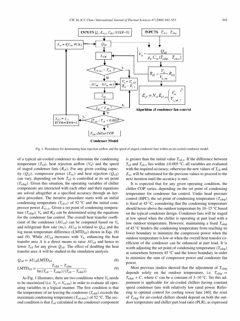
Fig. 1 gives flow charts showing how the aforementionedcontrol of condenser fans can be incorporated into the model
F.W. Yu, K.T. Chan / International Journal of Thermal Sciences 47 (2008) 942–953 945
Fig. 1. Procedures for determining heat rejection airflow and the speed of staged condenser fans within an air-cooled condenser model.
of a typical air-cooled condenser to determine the condensingtemperature (Tcd), heat rejection airflow (Va) and the speedof staged condenser fans (Rcf). For any given cooling capac-ity (Qcl), compressor power (Ecc) and heat rejection (Qcd)
can vary, depending on how Tcd is controlled at its set point(Tcdsp). Given this situation, the operating variables of chillercomponents are interacted with each other and their equationsare solved altogether at a specified accuracy through an iter-ative procedure. The iterative procedure starts with an initialcondensing temperature (Tcd,o) of 52 ◦C and the initial com-pressor power Ecc,o. Given a set point of condensing tempera-ture (Tcdsp), Va and Rcf can be determined using the equationsfor the condenser fan control. The overall heat transfer coeffi-cient of the condenser (AUcd) can be computed based on Vaand refrigerant flow rate (mr). AUcd is related to Qcd and thelog mean temperature difference (LMTDcd) shown in Eqs. (8)and (9). While AUcd increases with Va, enhancing the heattransfer area A is a direct means to raise AUcd and hence tolower Tcd for any given Qcd. The effect of doubling the heattransfer area A will be studied in the simulation analysis.
Qcd = AUcdLMTDcd (8)
LMTDcd = Tcdal − Tcdae
ln((Tcd − Tcdae)/(Tcd − Tcdal))(9)
As Fig. 1 illustrates, there are two conditions where Va needsto be maximized (i.e. Va = Va,tot) in order to evaluate all oper-ating variables in a logical manner. The first condition is thatthe temperature of air leaving the condenser (Tcdal) exceeds themaximum condensing temperature (Tcd,max) of 52 ◦C. The sec-ond condition is that Tcd calculated in the condenser component
is greater than the initial value Tcd,o. If the difference betweenTcd and Tcd,o lies within ±0.005 ◦C, all variables are evaluatedwith the required accuracy; otherwise the new values of Tcd andEcc will be substituted for the previous values to proceed to thenext iteration until the accuracy is met.
It is expected that for any given operating condition, thechiller COP varies, depending on the set point of condensingtemperature for condenser fan control. Under head pressurecontrol (HPC), the set point of condensing temperature (Tcdsp)
is fixed at 45 ◦C, considering that the condensing temperatureshould hover above the outdoor temperature by 10–15 ◦C basedon the typical condenser design. Condenser fans will be stagedat low speed when the chiller is operating at part load with alow outdoor temperature. However, maintaining a fixed Tcdsp
of 45 ◦C hinders the condensing temperature from reaching itslower boundary to minimize the compressor power when theoutdoor temperature is low or when the overall heat transfer co-efficient of the condenser can be enhanced at part load. It isworth adjusting the set point of condensing temperature (Tcdsp)
at somewhere between 45 ◦C and the lower boundary in orderto minimize the sum of compressor power and condenser fanpower.
Most previous studies showed that the adjustment of Tcdsp
depends solely on the outdoor temperature, i.e. Tcdsp =Tcdae + C, where C can be a constant of 3–10 ◦C. Yet this ad-justment is applicable for air-cooled chillers having constantspeed condenser fans with relatively low rated power. Refer-ring to optimal control for cooling tower fans [40], the resetof Tcdsp for air-cooled chillers should depend on both the out-door temperature and chiller part load ratio (PLR), as expressed

946 F.W. Yu, K.T. Chan / International Journal of Thermal Sciences 47 (2008) 942–953
by Eq. (10), where a1 to a6 are constant coefficients to be deter-mined for individual chillers with their own condenser designand fan power rating. The inclusion of the terms with PLR isessential when a chiller contains an air-cooled condenser withhigh fan power rating.
Tcdsp = Tcdae + (a1 + a2PLR + a3PLR2 + a4Tcdae
+ a5T2cdae + a6PLRTcdae) (10)
The lower boundary of condensing temperature is governedby the requirement of compressor lubrication and the heat re-jection capacity of condensers. With regard to air-cooled recip-rocating chillers, the condensing temperature should be above20 ◦C in order to maintain lubricating oil with suitable viscosityto return to the compressors [34]. It is possible to identify theconstraints on heat rejection capacity via a chiller model whichis able to account for the possible change of the condenser’sheat transfer characteristics at part load operation.
3. Example of applying optimal condenser fan control toair-cooled chillers
3.1. Description of the chiller model
To illustrate how the aforementioned control interacts withthe compressor power and condenser fan power of a chiller,a thermodynamic model for air-cooled centrifugal chillerswas developed using the simulation program TRNSYS ver-sion 15 [37]. The model considers mechanistic relations be-tween chiller components. The log mean temperature difference(LMTD) method was used to model the heat transfer character-istics of the evaporator and condenser under the full load andpart load conditions. The compressor and condenser have tosatisfy the mass balance of refrigerant and energy balance atthe evaporator. The model contains an algorithm to computethe required heat rejection airflow and the number and speedof condenser fans based on a set point of condensing tempera-ture. The structure of the model is based on the thermodynamicmodels used extensively to investigate the energy performanceof air-cooled reciprocating or screw chillers [33–36]. The wayto simulate the capacity control of the inlet guide vanes is basedon the steady-state model of a centrifugal compressor given inRefs. [38,39]. The model was validated by using the data of anexisting air-cooled centrifugal chiller (rated at 1266 kW) oper-ating for a wide range of ambient and load conditions. Detailsabout the development and validity of the chiller model aregiven in Ref. [39].
The chiller model is capable of investigating the steady-state behaviour of chiller COP under various operating con-ditions when the design and control of air-cooled condensersare changed. With the control algorithm of condenser fans, themodel can search for the optimum set point of condensing tem-perature from 20 to 45 ◦C at small intervals of 0.05 ◦C to mini-mize the sum of compressor power and condenser fan power forany given operating condition—a combination of chiller partload ratios and outdoor temperatures. The coefficients given inEq. (10) can then be identified based on the optimum set pointfor each operating condition.
The model consists of five inputs: outdoor temperature(Tcdae), cooling capacity (Qcl), chilled water flow rate (mw),the temperature of supply chilled water (Tchws) and the de-gree of subcooling (Tcdsc). Tcdae and Qcl are readily availablebased on the load profile of chillers. mw, Tchws and Tcdsc can beconsidered as constants for a given chiller’s nominal capacity.The outputs are the operating variables of the chiller compo-nents and the chiller COP. The annual electricity consumptionof chillers in a cooling plant can be calculated by the model,given the cooling load profile of a building and the schedule ofstaging the chillers.
It should be noted that none of the existing building en-ergy simulation programs can perform the energy analysis ofair-cooled chillers with various designs and controls of con-densers. This is because these programs usually model the en-ergy performance of chillers using regression curves based onspecific combinations of outdoor temperatures and load con-ditions. Such curves disregard the possible changes of chillerCOP under part load conditions with varying outdoor tempera-tures and different controls of condensing temperature.
3.2. Improved part load performance due to optimalcondenser fan control and enhanced condenser design
Drawing on the thermodynamic model, a variation in chillerCOP was investigated under various operating conditions withdifferent controls of condensing temperature and improved con-denser design. Fig. 2 shows the typical part load performancecurves when the chiller operated under HPC (the base case).The capacity control of the inlet guide vanes in the compres-sor resulted in the maximum COP at a part load ratio of 0.77to 0.83 for a constant outdoor temperature. This is contrary tothe maximum chiller COP at full load with regard to air-cooledchillers with reciprocating or screw compressors at constantspeed [33–36]. The chiller COP dropped considerably when thechiller load reduced from such part load ratios. This is due to
Fig. 2. Part load performance curves of the chiller under head pressure control(the base case).

F.W. Yu, K.T. Chan / International Journal of Thermal Sciences 47 (2008) 942–953 947
Fig. 3. Part load performance curves of the chiller with optimum set point ofcondensing temperature.
the significant drop in the compression efficiency during off-design operation, particularly with a high condensing temper-ature. HPC hindered the improvement of chiller COP at a lowload when the outdoor temperature dropped from a design levelof 35 ◦C.
As Fig. 3 illustrates, the chiller COP could increase in var-ious degrees under different operating conditions when the setpoint of condensing temperature was optimized to minimize thesum of compressor power and condenser fan power. To achievethe maximum chiller COP, the optimum set point of condens-ing temperature (Tcdsp,op) should increase with the chiller partload ratio (PLR) from 0.2 to 1 for a constant outdoor tempera-ture (Tcdae). Eq. (11) is a mathematical function of Tcdsp,op forthe chiller with the given condenser design and fan power rat-ing.
Tcdsp,op ={20 ◦C for Tcdae < 15 ◦C
(Tcdae − 3.2211PLR2 + 11.113PLR+ 2.1587) ◦C for 15 ◦C � Tcdae
(11)
By comparing the part load performance curves in Fig. 2with those in Fig. 3, it is possible to identify the extent to whichthe COP could rise when the optimum set point of condensingtemperature was applied. The increase of the chiller COP couldvary from 3.4 to 188%. Such an increase is small but notice-able at full load and is prominent at low chiller loads with lowoutdoor temperatures. The maximum chiller COP occurred at apart load ratio of 0.70 to 0.77, which is slightly different fromthe optimum range of part load ratios under HPC.
The potential benefits of enhancing the condenser capacitywere studied. Fig. 4 shows the percentage increase in chillerCOP under various operating conditions when the heat transferarea of the condenser was doubled while HPC was still used.The increase could vary by 2.3–13.8%, depending on the out-door temperatures and load conditions. It is interesting to seethat the percentage increase of chiller COP is highest at full loadat the designed outdoor temperature when doubling the heat
Fig. 4. Percentage increase in chiller COP when doubling the heat transfer areaof the condenser in relation to the base case.
Fig. 5. Percentage increase in chiller COP when doubling the flow capacity ofcondenser fans in relation to the base case.
transfer area of the condenser. This is contrary to the behav-iour of the improved COP resulting from the optimum set pointof condensing temperature. Indeed, the increased heat transferarea of the condenser helps enhance the heat rejection and, inturn, the refrigeration effect via increasing the subcooling effectof the condenser. For any given cooling capacity, the refriger-ant flow rate can drop due to the increased refrigeration effect,resulting in the reduction in both the compressor power andcondenser fan power. The enhancement of heat rejection capac-ity is greater when the chiller carries larger loads with a higherrefrigerant flow rate.
As Fig. 5 illustrates, when the airflow capacity of the con-denser was doubled, the chiller COP under HPC could increaseby 0.95–13.2%. Such a percentage increase is due only to thereduced power of the condenser fans which varied in proportion

948 F.W. Yu, K.T. Chan / International Journal of Thermal Sciences 47 (2008) 942–953
Fig. 6. Percentage increase in chiller COP when applying double-heat transferarea and optimum set point of condensing temperature in relation to the basecase.
to their speed cubed while producing the same heat rejectionairflow. Indeed, the fan power dropped by 67–84% from the fanpower found in the base case, though the double-flow capacityled to a doubling of the nominal power of the condenser fans.The compressor power remained unchanged in relation to thebase case as long as HPC was applied with a fixed set point of45 ◦C in the condensing temperature.
When the double-heat transfer area and optimum set point ofcondensing temperature were implemented together, the chillerCOP could increase by 11.4–237.2%, as shown in Fig. 6. For aconstant outdoor temperature, the percentage increase of COPgenerally rose when the chiller load dropped from a full load.When the outdoor temperature dropped, the condenser had am-ple heat rejection capacity to further lower the condensing tem-perature, resulting in the considerable increase in the chillerCOP. It is noted that the optimum set point of condensing tem-perature, when determined based on the original condenser de-sign, is still applicable to the case where the heat transfer areaof the condenser was doubled.
Similar to doubling the heat transfer area, the double-flowcapacity of the condenser fans could result in a 15.5–229.1%increase in the chiller COP when the optimum set point ofcondensing temperature took place, as shown in Fig. 7. Thepercentage increase of the chiller COP at full load in the double-flow case is higher than that in the double-heat transfer areacase. It is noted that the optimum set point of condensing tem-perature should be re-adjusted when there is a change in theflow capacity and power rating of condenser fans. When theflow capacity was doubled, the set point of condensing temper-ature had to drop by 0.25–3.6 ◦C, depending on the ambient andload conditions, in order to achieve the maximum chiller COP.
Overall, when the enhanced condenser design is used to-gether with the optimum set point of condensing temperature,the chiller COP could increase by at least 50% in moderate out-door temperatures ranging between 11 and 25 ◦C. This range
Fig. 7. Percentage increase in chiller COP when applying double-flow capacityand optimum set point of condensing temperature in relation to the base case.
accounts for 48% of the total cooling hours for office buildingsand for 54% of the total cooling hours for hotels, based on localweather conditions [41].
Using the condensing temperature reset to implement theoptimal condenser fan control calls for the monitoring of theoutdoor temperature and chiller load. A chiller part load ratio isusually not monitored directly by a chiller microprocessor be-cause the signal of chilled water flow rate is not received by themicroprocessor. If a chiller runs with its nominal flow for all op-erating conditions, it is possible to determine the part load ratioby using the difference between the temperatures of supply andreturn chilled water which are monitored variables. Consideringthat all the temperature variables are measured by thermistorswith a typical uncertainty of ±0.1 ◦C in the entire measurementrange, the combined uncertainty of Tcdsp,op given by Eq. (11)could be calculated to be ±0.08 ◦C at 45 ◦C to ±0.57 ◦C at20 ◦C. Fig. 8 shows how the uncertainty of Tcdsp,op influencesthe maximum COPs at the various operating conditions givenin Fig. 3. It is acceptable that the maximum COP deviates byup to 1.4% if the measurement uncertainty is considered in thecondensing temperature reset for condenser fan control.
4. Implementation of improved condenser fan controlusing the Equal Marginal Performance Principle (EMPP)
To perform the condensing temperature reset for optimalcondenser fan control, it is essential to have a dedicated con-troller which calculates the optimum set point based on sig-nals of outdoor temperatures and the temperature differences ofchilled water, and operates the fans at the right speed to meetthat set point. While this temperature reset control is an add-on for typical condenser fan operations, it would demand moresophisticated control and instrumentation techniques to verifywhether the chiller performance is optimized at the given fanspeed. To counter this, Hartman [42] proposed the EMPP whichtakes into account system components and their power relation-

F.W. Yu, K.T. Chan / International Journal of Thermal Sciences 47 (2008) 942–953 949
Fig. 8. Percentage change of maximum COP at various operating conditions due to the measurement uncertainty of the optimum condensing temperature set point(a) with negative error and (b) with positive error.
ship as a whole to ensure the optimal operation of any HVACsystem. Using EMPP would eliminate instrumentation issuesarising from temperature or pressure control which could di-minish the potential COP improvements. Under EMPP, the en-ergy performance of any system operating with multiple mod-ulating components is optimized when the change in systemoutput (called the marginal system output) per unit energy in-put is the same for all individual components in the system.
With regard to the chiller studied, the output is the cool-ing capacity (Qcl) and the components consuming power arethe compressor and condenser fans. One prerequisite for us-ing the EMPP is to develop an algorithm for the system thatrelates output as a function of the power input of the twocomponents. Based on the simulation results, it is possible togenerate a set of formulae to represent the output (Qcl) bythe compressor power (Ecc) and condenser fan power (Ecf)
at different outdoor temperatures, as summarized in Table 1.According to EMPP, the system is optimized or the maximum(marginal) COP takes place when the partial derivative of theoutput with respect to each power component is equal to eachother (i.e. ∂Qcl/∂Ecc = ∂Qcl/∂Ecf). Using the optimized re-lationship between the compressor power and fan power, theactual fan power for maximum COP was ascertained for eachoperating condition. The fan rotating speed was then identifiedbased on the fan law expressed in Eq. (12). Table 1 gives thefan speed required to be controlled at various operating con-ditions under EMPP. The implementation of EMPP relies onthe new demand-based control which performs improved oper-ation of HVAC systems based on optimized power relationshipsrather than using some calculated temperature or pressure setpoints which may not be directly related to system optimiza-tion. Although the EMPP is simple to apply and generic formost HVAC systems or equipment, it can be difficult or timeconsuming to determine the system output in terms of power re-lationships and to derive the marginal COP for each componentif there is interdependence in the performance of the systemcomponents.
Fan speed = (Design full speed)
×(actual fan power as a ratio to the rated power)1/3 (12)
5. Potential benefits from the improved control
The cooling load profile of a reference office building inHong Kong was considered in order to assess the potential elec-tricity savings when the enhanced condenser design and theimproved control of condenser fans were applied to air-cooledcentrifugal chillers. Detailed features of the building are givenin Refs. [41,43]. The building has 40 storeys and a gross floorarea (GFA) of 51 840 m2 and its air-conditioned areas accountfor 82.6% of the GFA. Fig. 9 is a histogram showing how manyhourly data of building cooling loads were collected in variousranges of outdoor temperatures. The data were expressed as ra-tios to the peak building cooling load of 6389 kW. There are2834 cooling hours which account for 90.5% of the total of-fice hours (3131 h a year). The annual cooling energy for thebuilding is 7 423 883 kWh based on local weather conditions ofthe test reference year (TRY) in 1989. TRY is considered rep-resentative of the prevailing weather conditions in Hong Kongfor building energy analysis [44]. As Fig. 9 illustrates, data ofhigher building load ratios were generally gathered at higheroutdoor temperatures with a narrower range. For about 60% ofthe total cooling hours the building load ratios are 0.5 or be-low. The chillers needed to operate frequently for the buildingload ratio of 0.1 to 0.2 with a wide range of 11 to 25 ◦C in theoutdoor temperature.
To meet the peak building cooling load, the chiller plantwas designed with six identical air-cooled centrifugal chillersrated at 1124 kW each. There is a single-loop pumping sys-tem with a differential pressure by-pass pipe to control theamount of chilled water flowing from the operating chillers tocooling coils of the airside equipment. There are six constantspeed pumps, each dedicated to one chiller to provide a con-stant chilled water flow of 47 l/s. Each pump has a rated powerof 31.3 kW.

950 F.W. Yu, K.T. Chan / International Journal of Thermal Sciences 47 (2008) 942–953
Table 1Expression of system output and optimum condenser fan power under EMPP
Outdoortemperature(◦C)
Coolingcapacity(% of max.)
System output formulae Optimum fanspeed (% of fullspeed)
Optimum fanpower (% ofrated power)
MaximumCOP
15 100 Qcl = 246.8E−0.2046cc E0.7981
cf 96.34 89.42 6.31
15 75 Qcl = 246.8E−0.2046cc E0.7981
cf 82.59 56.33 7.10
15 50 Qcl = 246.8E−0.2046cc E0.7981
cf 69.59 33.71 6.92
15 25 Qcl = 246.8E−0.2046cc E0.7981
cf 49.13 11.86 5.21
20 100 Qcl = 5371.7E−1.3793cc E1.7351
cf 99.06 97.19 5.08
20 75 Qcl = 5371.7E−1.3793cc E1.7351
cf 84.84 61.07 5.61
20 50 Qcl = 5371.7E−1.3793cc E1.7351
cf 71.77 36.97 5.31
20 25 Qcl = 5371.7E−1.3793cc E1.7351
cf 57.49 19.00 3.84
25 100 Qcl = 377.9E−0.5443cc E1.2294
cf 99.69 99.07 4.19
25 75 Qcl = 377.9E−0.5443cc E1.2294
cf 87.27 66.47 4.58
25 50 Qcl = 377.9E−0.5443cc E1.2294
cf 73.60 39.87 4.25
25 25 Qcl = 377.9E−0.5443cc E1.2294
cf 59.09 20.63 2.98
30 100 Qcl = 56.4E−0.0534cc E0.9893
cf 99.74 99.21 3.51
30 75 Qcl = 56.4E−0.0534cc E0.9893
cf 89.91 72.69 3.82
30 50 Qcl = 56.4E−0.0534cc E0.9893
cf 76.11 44.08 3.50
30 25 Qcl = 56.4E−0.0534cc E0.9893
cf 61.44 23.19 2.40
35 100 Qcl = 14.6E0.2699cc E0.8241
cf 100 100 2.98
35 75 Qcl = 14.6E0.2699cc E0.8241
cf 92.80 79.91 3.23
35 50 Qcl = 14.6E0.2699cc E0.8241
cf 78.29 47.99 2.94
35 25 Qcl = 14.6E0.2699cc E0.8241
cf 63.34 25.41 1.98
Fig. 9. Frequency distribution of hourly building load ratios in different ranges of outdoor temperatures.
While air-cooled centrifugal chillers operate with maximumCOP at a part load ratio of 0.71 to 0.84, it is not desir-able to frequently operate the chillers at such part load ra-tios. This is because more pumping energy will be incurredalong with the frequent part load operation, which tends tooffset any energy savings of chillers operating closely at their
maximum COP. To meet the changing building cooling load,conventional chiller sequencing was still implemented so allthe chillers are operating at the same load, and no additionalchillers start to operate until each of the running chillers isoperating at full load. The schedule of staging chillers andtheir possible loading ranges were then determined, as shown

F.W. Yu, K.T. Chan / International Journal of Thermal Sciences 47 (2008) 942–953 951
Table 2Range of chiller part load ratios at different numbers of operating chillers under chiller sequencing
Building loadratio (BLR)
Number ofcooling hours
Number ofoperating chillers(Nch)
Total capacity ofoperating chillers(kW)
Chiller part loadratio (PLR)
0 < BLR � 0.18 746 1 1124 0.29–10.18 < BLR � 0.35 479 2 2248 0.5–10.35 < BLR � 0.53 568 3 3372 0.67–10.53 < BLR � 0.70 624 4 4496 0.75–10.70 < BLR � 0.87 405 5 5620 0.8–10.87 < BLR � 1 12 6 6744 0.83–0.95
Table 3Energy performance of chillers with various energy efficient measures
Case Average chiller Normalized annual electricity Electricity savingsCOP consumption of chillers (kWh/m2) w.r.t. base case (%)
1 (base case) 3.36 51.60 –2 (M1) 4.07 42.60 17.43 (M2) 3.41 50.88 1.44 (M3) 3.60 48.16 6.75 (M1 + M2) 4.62 37.51 27.36 (M1 + M3) 4.42 39.23 24.0
in Table 2. For a given Nch, the lower limit of the range ofchiller part load ratios was calculated by the total cooling ca-pacity at (Nch − 1) over the total cooling capacity at that Nch.When more chillers are staged to meet higher building cool-ing loads, each of them can operate more frequently at higherloads.
The annual electricity consumption of the chillers andpumps was calculated, based on the building cooling load pro-file and the schedule of staging chillers. The consumption isnormalized by the total air-conditioned floor area of the build-ing (i.e. 42 840 m2) in terms of kWh/m2. Table 3 shows theannual electricity consumption of the chillers under differentcases. Case 1 refers to the base case where all the chillerswith the conventional condenser design operated under HPC.Cases 2 to 6 refer to the individual and mixed use of energyefficient measures applied to all the chillers: (M1) optimumset point of condensing temperature; (M2) double-flow capac-ity of the condenser fans; (M3) double-heat transfer area ofthe condensers. The annual electricity consumption of pumpsis 5.85 kWh/m2 for cases 1 to 6 where the same schedule ofstaging chillers was applied.
Based on the electricity savings of the chillers, optimizingthe set point of condensing temperature (M1) is a prominent ap-proach to improving the energy performance of the chiller plant,enabling the average chiller COP to rise from 3.36 to 4.07. Theaverage chiller COP is defined as the annual cooling energy of abuilding in kWh divided by the annual electricity consumptionof chillers in kWh. If the flow capacity of the condenser fanswas doubled with a fixed condensing temperature set point of45 ◦C, the normalized annual electricity consumption of chillersreduced slightly by 1.4% or 0.72 kWh/m2. This reduction isdue to the decreased power of condenser fans running at lowspeed in most operating conditions in order to produce the min-imum airflow required to meet the high set point. Doubling theheat transfer area of the condensers could achieve an electric-
ity saving of 6.7% or 3.44 kWh/m2 even when the condensingtemperature was maintained at a high level of 45 ◦C.
When the optimum set point of condensing temperature wasapplied together with the enhanced condenser design, there isa decrease of up to 27.3% or 14.1 kWh/m2 in the annual elec-tricity consumption of the chillers. This electricity saving corre-lates closely to the increase in the chiller COP shown in Fig. 7.It is worth noting that in cases 5 and 6 the overall electricitysavings resulting from two energy efficient measures can beequal to or even greater than the sum of the electricity savingscontributed by the individual measures. In general, it is hardto achieve ultra-electricity savings when applying two or moreenergy efficient measures together because combining energyefficient measures tends to diminish their individual ability todecrease electricity consumption. Overall it is highly desirableto implement the optimum set point of condensing tempera-ture together with the double-flow capacity of condenser fansto magnify their potential electricity savings for an air-cooledchiller plant.
6. Conclusions
This paper presents the impact of optimizing the condenserfan control and condenser design to enhance the performance ofair-cooled chillers under various operating conditions. A gen-eral methodology has been explained to determine the optimalcondensing temperature set point for condenser fan controls. Anexample application of the improved control to an air-cooledcentrifugal chiller model showed that the COP could increaseby 11.4–237.2%, depending on the ambient and load condi-tions. It is possible to further improve the chiller COP by in-creasing the airflow capacity of condenser fans and the heattransfer area of air-cooled condensers, along with the optimalfan control. The use of the Equal Marginal Performance Prin-

952 F.W. Yu, K.T. Chan / International Journal of Thermal Sciences 47 (2008) 942–953
ciple to achieve optimized chiller performance has been dis-cussed.
The cooling load profile of an office building was con-sidered to identify the electricity savings of chillers resultingfrom the low-energy condenser fan control and condenser de-sign. It is estimated that the double-flow capacity of condenserfans together with the optimum set point of condensing tem-perature enables the annual electricity consumption per unitA/C floor area of chillers to drop by 27.3% or 14.1 kWh/m2,with regard to the building requiring an annual cooling en-ergy per unit A/C floor area of 173.3 kWh/m2. The findingsof this research provide important insights into how to im-prove the COP of air-cooled chillers operating for a buildingcooling load profile. It remains to be seen how life-cycle-cost analysis can be used to determine if the electricity sav-ings are worth the increased initial costs for implementingthe low-energy condenser features to an air-cooled chillerplant.
Acknowledgements
The work described in this paper was supported by a grantfrom the Research Grants Council of the Hong Kong SAR,China (Project No. PolyU 5112/05E).
References
[1] F.W. Yu, K.T. Chan, Energy signatures for assessing the energy perfor-mance of chillers, Energy and Buildings 37 (2005) 739–746.
[2] F.W.H. Yik, J. Burnett, I. Prescott, Predicting air-conditioning energy con-sumption of a group of buildings using different heat rejection methods,Energy and Buildings 33 (2001) 151–166.
[3] J.C. Lam, R.Y.C. Chan, C.L. Tsang, D.H.W. Li, Electricity use charac-teristics of purpose-built office buildings in subtropical climates, EnergyConversion & Management 45 (6) (2004) 829–844.
[4] B.N. Gidwani, Optimization of chilled water systems, Energy Engineer-ing 84 (5) (1987) 30–50.
[5] A. Kaya, Improving efficiency in existing chillers with optimization tech-nology, ASHRAE Journal 33 (10) (1991) 30–38.
[6] A. Beyene, Performance evaluation of conventional chiller systems,ASHRAE Journal 37 (6) (1995) 36–44.
[7] S.B. Austin, Optimum chiller loading, ASHRAE Journal 33 (7) (1991)40–43.
[8] G. Avery, Improving the efficiency of chilled water plants, ASHRAE Jour-nal 43 (5) (2001) 14–18.
[9] J.T. Cui, S.W. Wang, A model-based online fault detection and diagnosisstrategy for centrifugal chiller systems, International Journal of ThermalSciences 44 (2005) 986–999.
[10] D.D. Massie, Optimization of a building’s cooling plant for operatingcost and energy use, International Journal of Thermal Sciences 41 (2002)1121–1129.
[11] T. Hartman, All-variable speed centrifugal chiller plants, ASHRAE Jour-nal 43 (9) (2001) 43–53.
[12] R.N.N. Koury, L. Machado, K.A.R. Ismail, Numerical simulation of avariable speed refrigeration system, International Journal of Refrigera-tion 24 (2001) 192–200.
[13] S.V. Shelton, E.D. Weber, Modelling and optimization of commercialbuilding chiller/cooling tower systems, ASHRAE Transaction 97 (2)(1991) 1209–1216.
[14] S.A. Tassou, T.Q. Quereshi, Comparative performance evaluation ofpositive displacement compressors in variable-speed refrigeration ap-plications, International Journal of Refrigeration 21 (1) (1998) 29–41.
[15] A.K. Wong, R.W. James, Capacity control of a refrigeration system usinga variable speed compressor, Building Services Engineering Research &Technology 9 (2) (1988) 63–68.
[16] G. Mazurkiewicz, Better cooling via improved chillers, Air Conditioning,Heating & Refrigeration News 215 (15) (2002) 37–38.
[17] F.W. Yu, K.T. Chan, Optimum load sharing strategy for multiple-chillersystems serving air-conditioned buildings, Building and Environment 42(2007) 1581–1593.
[18] G. Avery, Controlling chillers in variable flow systems, ASHRAE Jour-nal 40 (2) (1998) 42–45.
[19] I. Dubov, Chilled water plant efficiency, ASHRAE Journal 45 (6) (2003)37–40.
[20] J.E. Braun, S.A. Klein, J.W. Mitchell, W.A. Beckman, Applications ofoptimal control to chilled water systems without storage, ASHRAE Trans-actions 95 (1) (1989) 663–675.
[21] M. Liu, Variable water flow pumping for central chilled water systems,Journal of Solar Energy Engineering 124 (3) (2002) 300–304.
[22] T. Moses, Variable-primary flow: important lessons learned, Heating/Piping/Air Conditioning Engineering 76 (7) (2004) 40–43.
[23] S.T. Taylor, Primary-only vs. primary secondary variable flow systems,ASHRAE Journal 44 (2) (2002) 25–29.
[24] W.P. Bahnfleth, E.B. Peyer, Varying views on variable-primary flow, Heat-ing/Piping/Air Conditioning Engineering 76 (3) (2004) S5–S9.
[25] J. Celuch, Hybrid chilled water plant, ASHRAE Journal 43 (7) (2001) 34–35.
[26] Y.C. Chang, J.K. Lin, M.H. Chuang, Optimal chiller loading by geneticalgorithm for reducing energy consumption, Energy & Buildings 37 (2)(2005) 147–155.
[27] M. Smith, G. King, Energy saving controls for air-cooled water chillers,Building Services Journal (April 1998) 47–48.
[28] M.A. Roper, Energy efficient chiller control (Technical Note TN 16/2000),Building Services Research and Information Association, Bracknell,2000.
[29] K.A. Manske, D.T. Reindl, S.A. Klein, Evaporative condenser control inindustrial refrigeration systems, International Journal of Refrigeration 24(2001) 676–691.
[30] G.C. Briley, Energy conservation in industrial refrigeration systems,ASHRAE Journal 45 (6) (2003) 46–47.
[31] Y.T. Ge, S.A. Tassou, Mathematical modelling of supermarket refrigera-tion systems for design, energy prediction and control, Proceedings of theInstitution of Mechanical Engineers 214 (A) (2000) 101–114.
[32] J.M. Gordon, K.C. Ng, Cool Thermodynamics, Cambridge InternationalScience Publishing, Cambridge, 2000.
[33] K.T. Chan, F.W. Yu, Applying condensing-temperature control in air-cooled reciprocating water chillers for energy efficiency, Applied En-ergy 72 (2002) 565–581.
[34] K.T. Chan, F.W. Yu, Optimum set point of condensing temperature for air-cooled chillers, International Journal of HVAC&R Research 10 (2) (2004)113–127.
[35] F.W. Yu, K.T. Chan, Advanced control of heat rejection airflow for improv-ing the coefficient of performance of air-cooled chillers, Applied ThermalEngineering 26 (2006) 97–110.
[36] F.W. Yu, K.T. Chan, Modelling of the coefficient of performance of anair-cooled screw chiller with variable speed condenser fans, Building andEnvironment 41 (2006) 407–417.
[37] Solar Energy Laboratory, TRNSYS 15: A Transient System SimulationProgram (Reference Manual), University of Wisconsin–Madison Press,Madison, WI, 2000.
[38] J.P. Bourdouxhe, M. Grodent, J.J. Lebrun, A toolkit for primary HVACsystem energy calculation (computer program), American Society ofHeating, Refrigerating and Air-Conditioning Engineers, Atlanta, GA,1995.
[39] F.W. Yu, K.T. Chan, Part load performance of air-cooled centrifugalchillers with variable speed condenser fan control, Building and Environ-ment 41 (2007) 407–417.
[40] C. Summers, R. Howell, Chilled water plant optimization based on part-load cooling tower performance, in: Proceedings of Clima 2000 Confer-ence, Brussels, 30 August–2 September, 1997.
F.W. Yu, K.T. Chan / International Journal of Thermal Sciences 47 (2008) 942–953 953
[41] F.W. Yu, K.T. Chan, An alternative approach for the performance ratingof air-cooled chillers used in air-conditioned buildings, Building and En-vironment 41 (2006) 1723–1730.
[42] T. Hartman, Designing efficient systems with the equal marginal perfor-mance principle, ASHRAE Journal 47 (7) (2005) 64–70.
[43] F.W. Yu, K.T. Chan, Low-energy design for air-cooled chiller plants inair-conditioned buildings, Energy and Buildings 38 (2006) 334–339.
[44] J.C. Lam, S.C.M. Hui, Outdoor design conditions for HVAC system de-sign and energy simulation for buildings in Hong Kong, Energy and Build-ings 22 (1) (1995) 25–43.


