Embed Size (px)
Citation preview
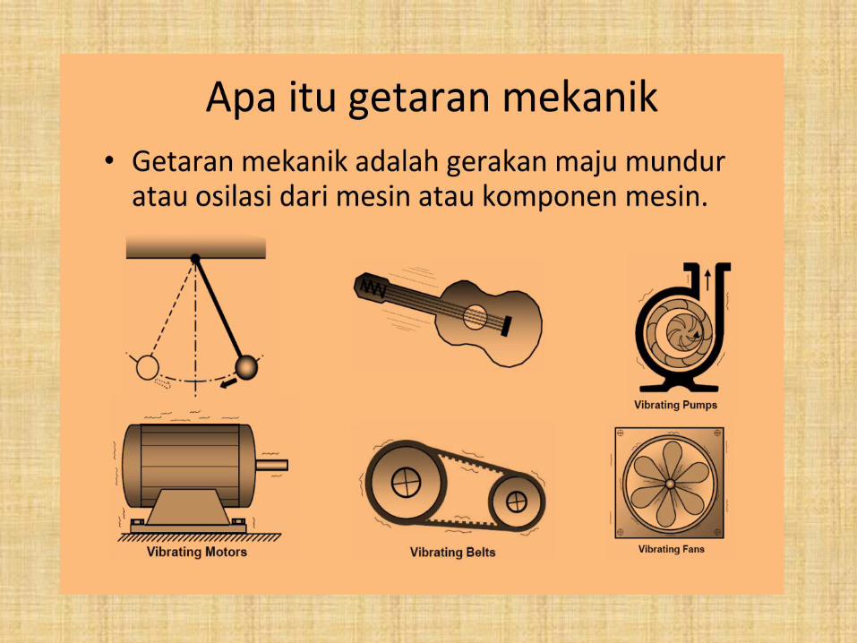
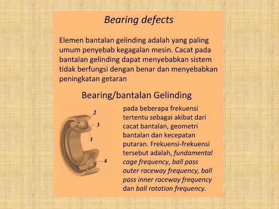
TEORI DASAR
ANALISA VIBRASI
Oleh :
DARYANTO
Predictive Maintenance – CRM
PT KRAKATAU STEEL - CILEGON
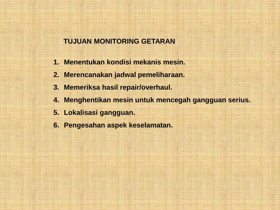
TUJUAN MONITORING GETARAN
1. Menentukan kondisi mekanis mesin.
2. Merencanakan jadwal pemeliharaan.
3. Memeriksa hasil repair/overhaul.
4. Menghentikan mesin untuk mencegah gangguan serius.
5. Lokalisasi gangguan.
6. Pengesahan aspek keselamatan.
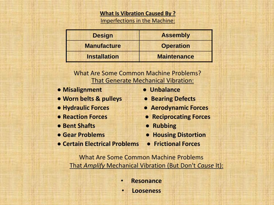
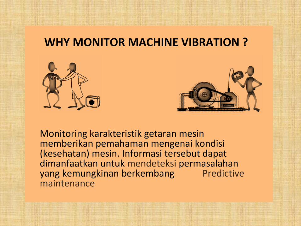
What Is Vibration Caused By ? Imperfections in the Machine:
Design Assembly
Manufacture Operation
Installation Maintenance
What Are Some Common Machine Problems? That Generate Mechanical Vibration:
● Misalignment ● Unbalance
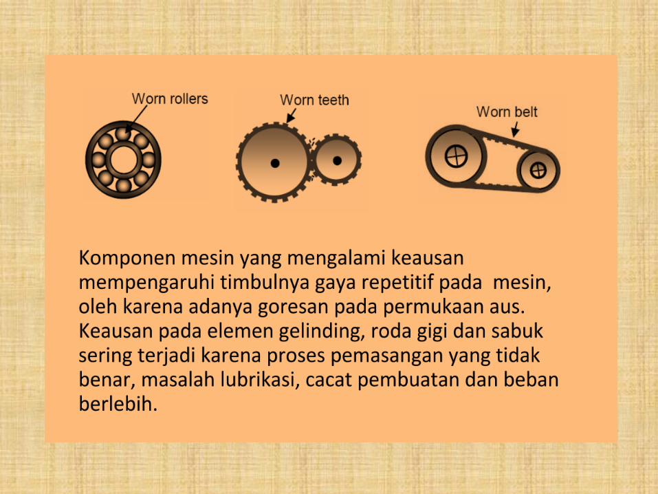
● Worn belts & pulleys ● Bearing Defects
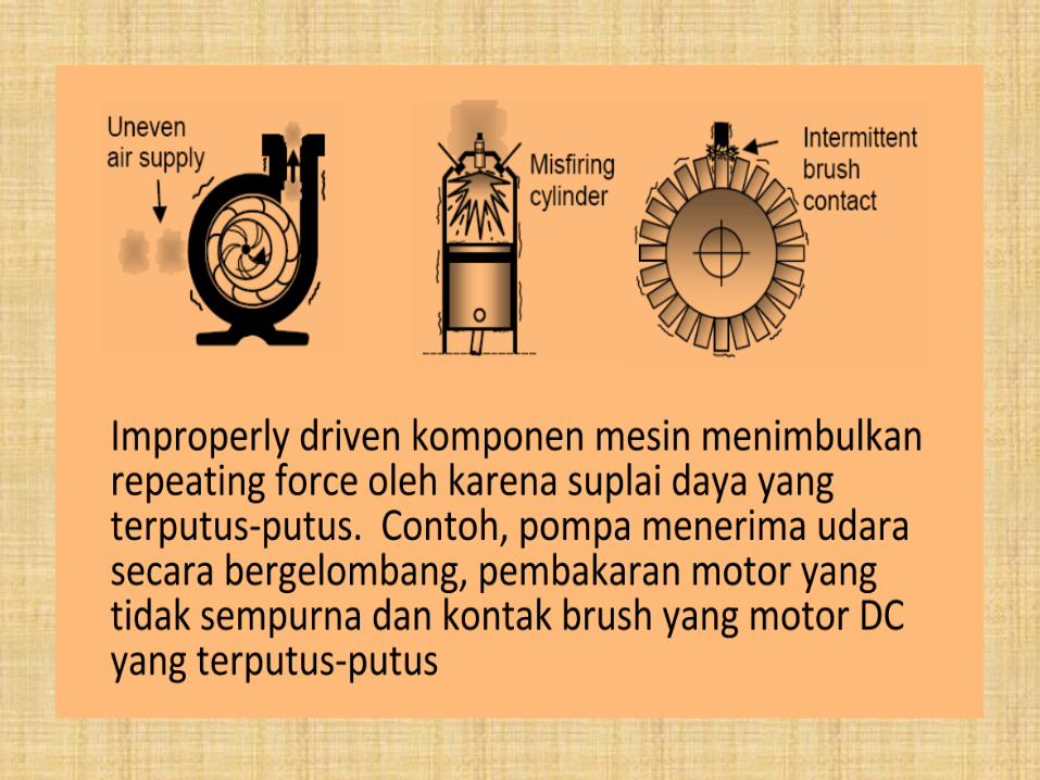
● Hydraulic Forces ● Aerodynamic Forces
● Reaction Forces ● Reciprocating Forces
● Bent Shafts ● Rubbing
● Gear Problems ● Housing Distortion
● Certain Electrical Problems ● Frictional Forces
What Are Some Common Machine Problems That Amplify Mechanical Vibration (But Don't Cause It):
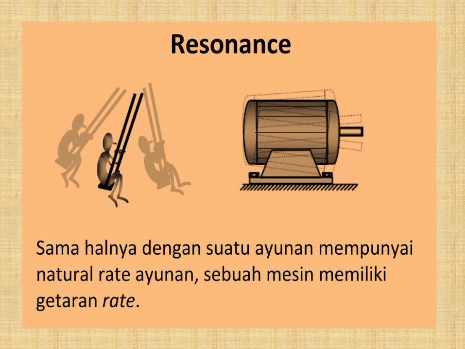
• Resonance
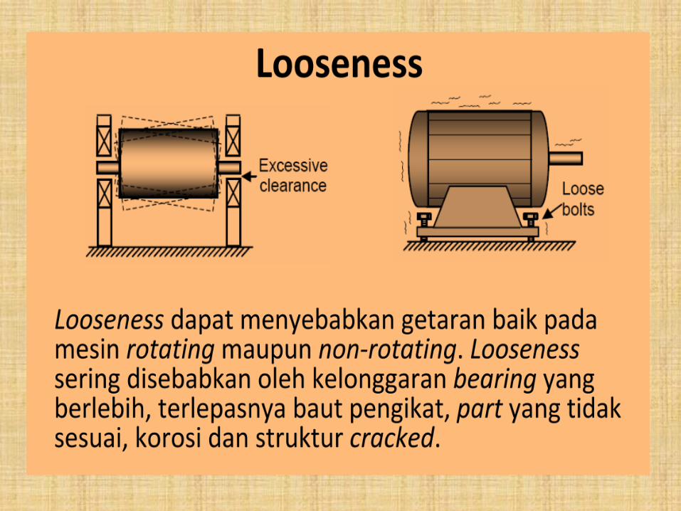
• Looseness
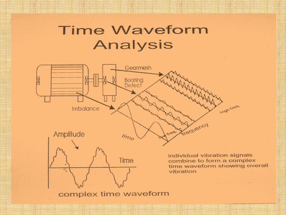
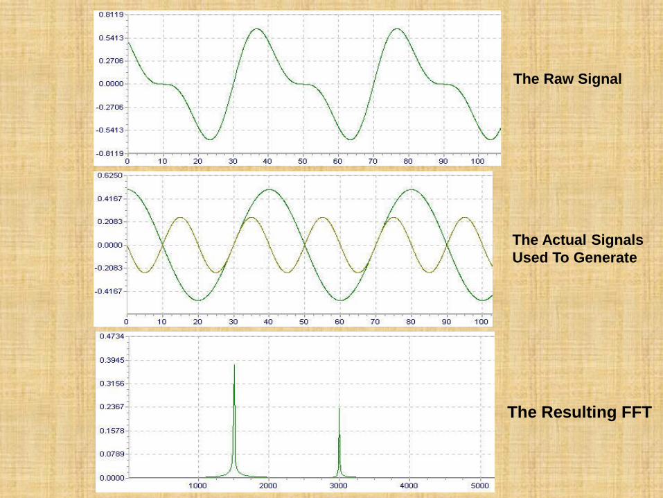
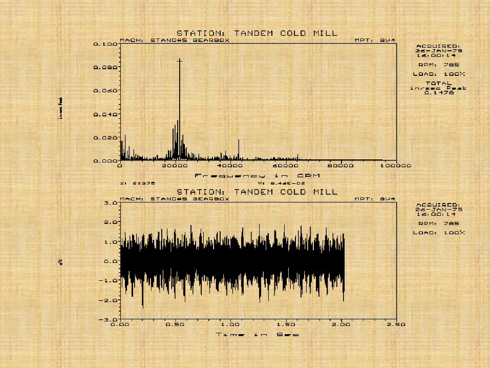
The Resulting FFT
The Raw Signal
The Actual Signals
Used To Generate
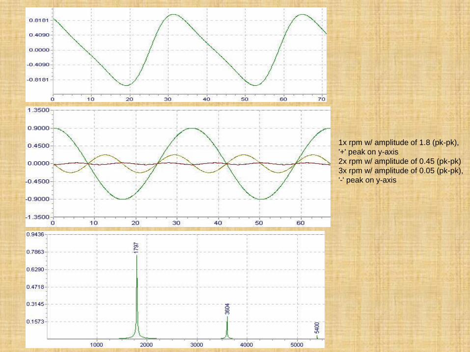
1x rpm w/ amplitude of 1.8 (pk-pk),
'+' peak on y-axis
2x rpm w/ amplitude of 0.45 (pk-pk)
3x rpm w/ amplitude of 0.05 (pk-pk),
'-' peak on y-axis
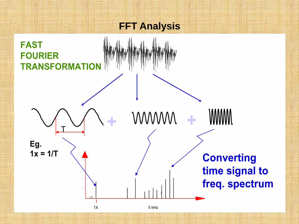
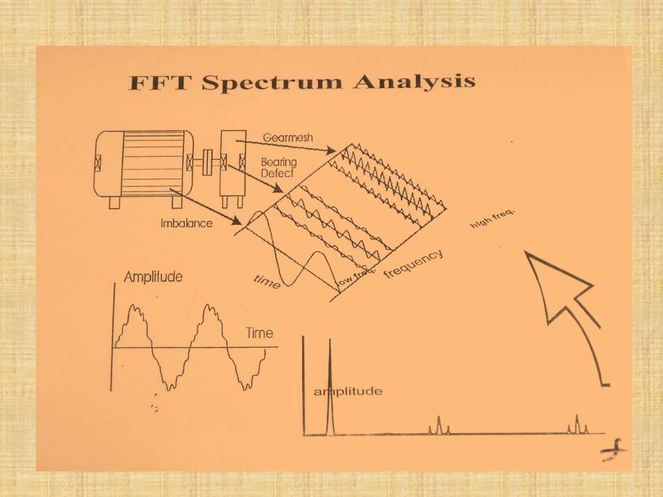
FFT Analysis
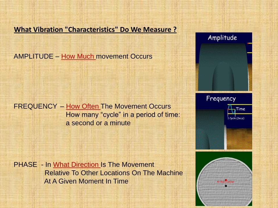
AMPLITUDE – How Much movement Occurs
FREQUENCY – How Often The Movement Occurs
How many “cycle” in a period of time:
a second or a minute
PHASE - In What Direction Is The Movement
Relative To Other Locations On The Machine
At A Given Moment In Time
What Vibration "Characteristics" Do We Measure ?
0 1000 2000 3000 4000 5000 6000 7000 8000 9000 10000 11000 12000 13000 14000 15000 16000 17000 18000 19000 20000 21000 22000 23000 24000
0,00
0,02
0,04
0,06
0,08
0,10
0,12
0,14
0,16
0,18
0,20
0,22
0,24
0,26
0,28
0,30
0,32
0,34
0,36
0,38
0,40
0,42
0,44
0,46
0,48
0,50
0,52
0,54
0,56
0,58
0,60
0,62
0,64
0,66
0,68
0,70
0,72
0,74
0,76
0,78
0,80
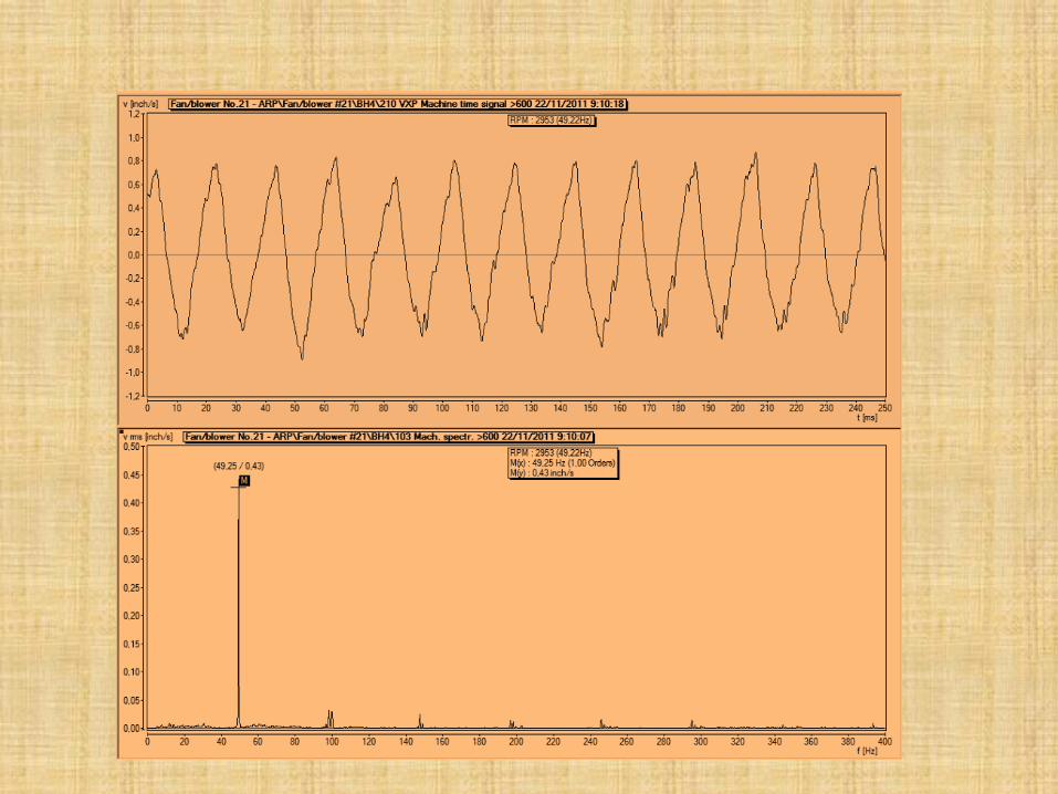
Fan/ blower No.21 - ARP\ Fan/ blower # 21\ BH4\ 103 Mac h. spec tr. >600 22/ 11/ 2011 9:10:07
M
(2955,00 / 0,43)
f [cpm]
v rms [inch/ s]
RPM : 2953 (49,22Hz)
M(x) : 2955,00 cpm (1,00 Orders)
M(y) : 0,43 inch/ s
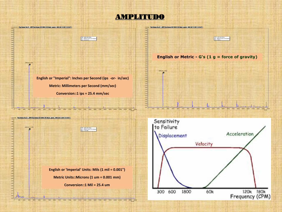
AMPLITUDO
0 1000 2000 3000 4000 5000 6000 7000 8000 9000 10000 11000 12000 13000 14000 15000 16000 17000 18000 19000 20000 21000 22000 23000 24000
0,00
0,02
0,04
0,06
0,08
0,10
0,12
0,14
0,16
0,18
0,20
0,22
0,24
0,26
0,28
0,30
0,32
0,34
0,36
0,38
0,40
0,42
0,44
0,46
0,48
0,50
0,52
0,54
0,56
0,58
0,60
0,62
0,64
0,66
0,68
0,70
0,72
0,74
0,76
0,78
0,80
Fan/ blower No.21 - ARP\ Fan/ blower # 21\ BH4\ 103 Mac h. spec tr. >600 22/ 11/ 2011 9:10:07
M
(2955,00 / 0,342)
f [cpm]
a rms [g]
RPM : 2953 (49,22Hz)
M(x) : 2955,00 cpm (1,00 Orders)
M(y) : 0,342 g
0 1000 2000 3000 4000 5000 6000 7000 8000 9000 10000 11000 12000 13000 14000 15000 16000 17000 18000 19000 20000 21000 22000 23000 24000
0,00
0,05
0,10
0,15
0,20
0,25
0,30
0,35
0,40
0,45
0,50
0,55
0,60
0,65
0,70
0,75
0,80
0,85
0,90
0,95
1,00
1,05
1,10
1,15
1,20
1,25
1,30
1,35
1,40
1,45
1,50
1,55
1,60
Fan/ blower No.21 - ARP\ Fan/ blower # 21\ BH4\ 103 Mac h. spec tr. >600 22/ 11/ 2011 9:10:07
M
(2955,00 / 1,378)
f [cpm]
s rms [mils]
RPM : 2953 (49,22Hz)
M(x) : 2955,00 cpm (1,00 Orders)
M(y) : 1,378 mils
English or 'Imperial' Units: Mils (1 mil = 0.001")
Metric Units::Microns (1 um = 0.001 mm)
Conversion::1 Mil = 25.4 um
English or "Imperial": Inches per Second (ips -or- in/sec)
Metric: Millimeters per Second (mm/sec)
Conversion::1 ips = 25.4 mm/sec
English or Metric - G's (1 g = force of gravity)
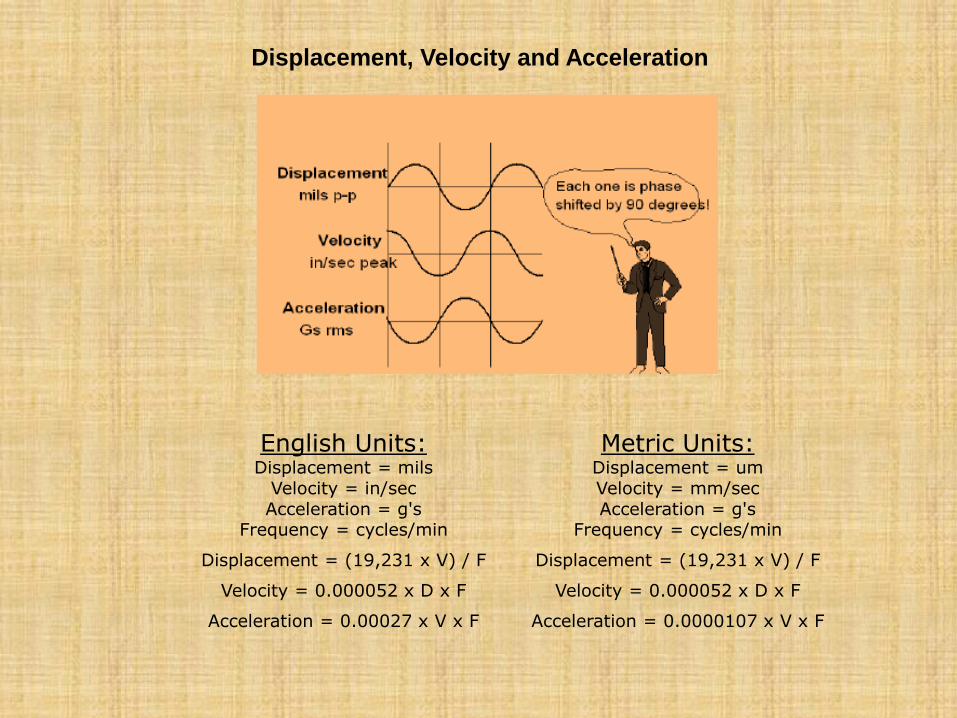
English Units:
Displacement = mils
Velocity = in/sec
Acceleration = g's
Frequency = cycles/min
Metric Units:
Displacement = um
Velocity = mm/sec
Acceleration = g's
Frequency = cycles/min
Displacement = (19,231 x V) / F Displacement = (19,231 x V) / F
Velocity = 0.000052 x D x F Velocity = 0.000052 x D x F
Acceleration = 0.00027 x V x F Acceleration = 0.0000107 x V x F
Displacement, Velocity and Acceleration
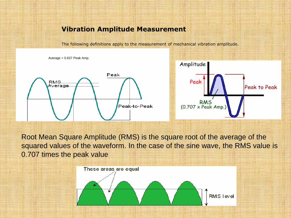
Vibration Amplitude Measurement
The following definitions apply to the measurement of mechanical vibration amplitude.
Root Mean Square Amplitude (RMS) is the square root of the average of the
squared values of the waveform. In the case of the sine wave, the RMS value is
0.707 times the peak value
Average = 0.637 Peak Amp.
0 1000 2000 3000 4000 5000 6000 7000 8000 9000 10000 11000 12000 13000 14000 15000 16000 17000 18000 19000 20000 21000 22000 23000 24000
0,00
0,02
0,04
0,06
0,08
0,10
0,12
0,14
0,16
0,18
0,20
0,22
0,24
0,26
0,28
0,30
0,32
0,34
0,36
0,38
0,40
0,42
0,44
0,46
0,48
0,50
Fan/ blower No.21 - ARP\ Fan/ blower # 21\ BH4\ 103 Mac h. spec tr. >600 22/ 11/ 2011 9:10:07
M
(2955,00 / 0,43)
f [cpm]
v rms [inch/ s]
RPM : 2953 (49,22Hz)
M(x) : 2955,00 cpm (1,00 Orders)
M(y) : 0,43 inch/ s
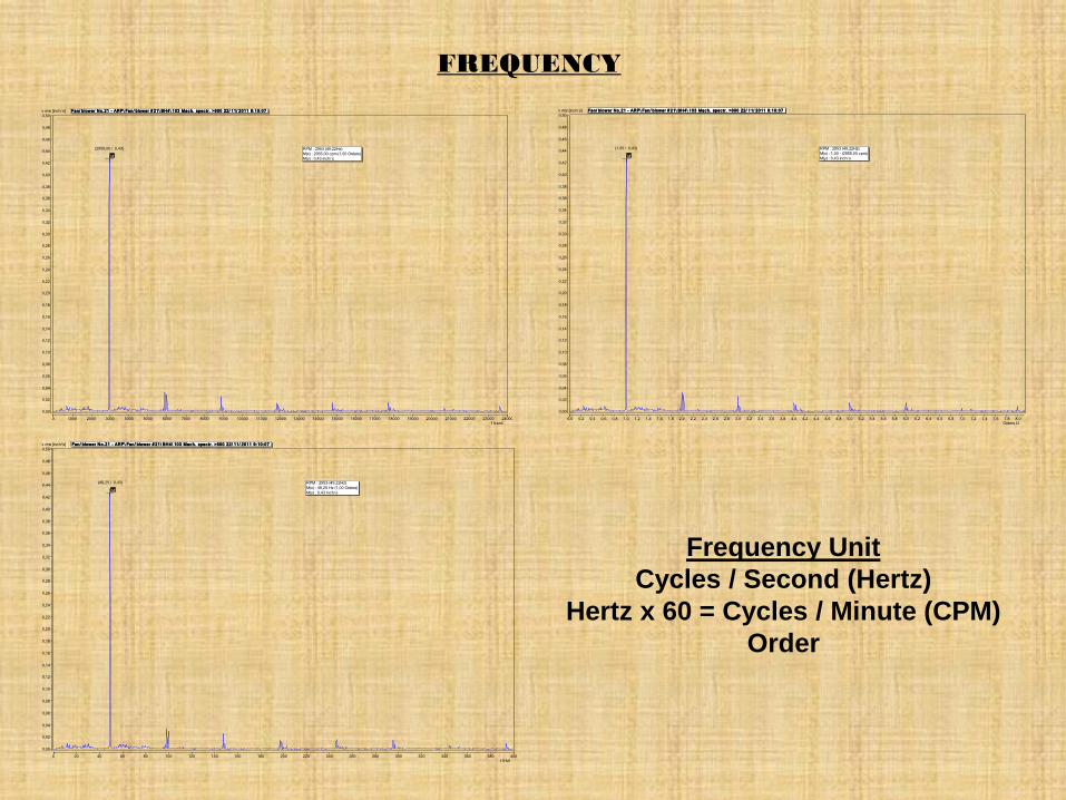
FREQUENCY
0,0 0,2 0,4 0,6 0,8 1,0 1,2 1,4 1,6 1,8 2,0 2,2 2,4 2,6 2,8 3,0 3,2 3,4 3,6 3,8 4,0 4,2 4,4 4,6 4,8 5,0 5,2 5,4 5,6 5,8 6,0 6,2 6,4 6,6 6,8 7,0 7,2 7,4 7,6 7,8 8,0
0,00
0,02
0,04
0,06
0,08
0,10
0,12
0,14
0,16
0,18
0,20
0,22
0,24
0,26
0,28
0,30
0,32
0,34
0,36
0,38
0,40
0,42
0,44
0,46
0,48
0,50
Fan/ blower No.21 - ARP\ Fan/ blower # 21\ BH4\ 103 Mac h. spec tr. >600 22/ 11/ 2011 9:10:07
M
(1,00 / 0,43)
Orders [-]
v rms [inch/ s]
RPM : 2953 (49,22Hz)
M(x) : 1,00 - (2955,00 cpm)
M(y) : 0,43 inch/ s
Frequency Unit
Cycles / Second (Hertz)
Hertz x 60 = Cycles / Minute (CPM)
Order
0 20 40 60 80 100 120 140 160 180 200 220 240 260 280 300 320 340 360 380 400
0,00
0,02
0,04
0,06
0,08
0,10
0,12
0,14
0,16
0,18
0,20
0,22
0,24
0,26
0,28
0,30
0,32
0,34
0,36
0,38
0,40
0,42
0,44
0,46
0,48
0,50
Fan/ blower No.21 - ARP\ Fan/ blower # 21\ BH4\ 103 Mac h. spec tr. >600 22/ 11/ 2011 9:10:07
M
(49,25 / 0,43)
f [Hz]
v rms [inch/ s]
RPM : 2953 (49,22Hz)
M(x) : 49,25 Hz (1,00 Orders)
M(y) : 0,43 inch/ s
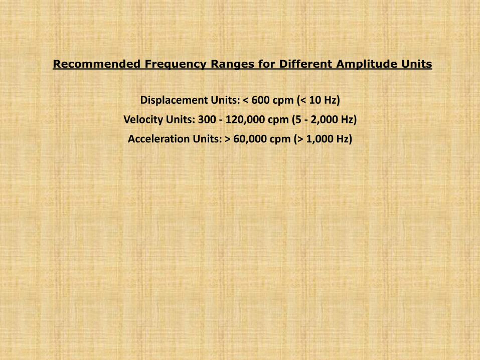
Displacement Units: < 600 cpm (< 10 Hz)
Velocity Units: 300 - 120,000 cpm (5 - 2,000 Hz)
Acceleration Units: > 60,000 cpm (> 1,000 Hz)
Recommended Frequency Ranges for Different Amplitude Units
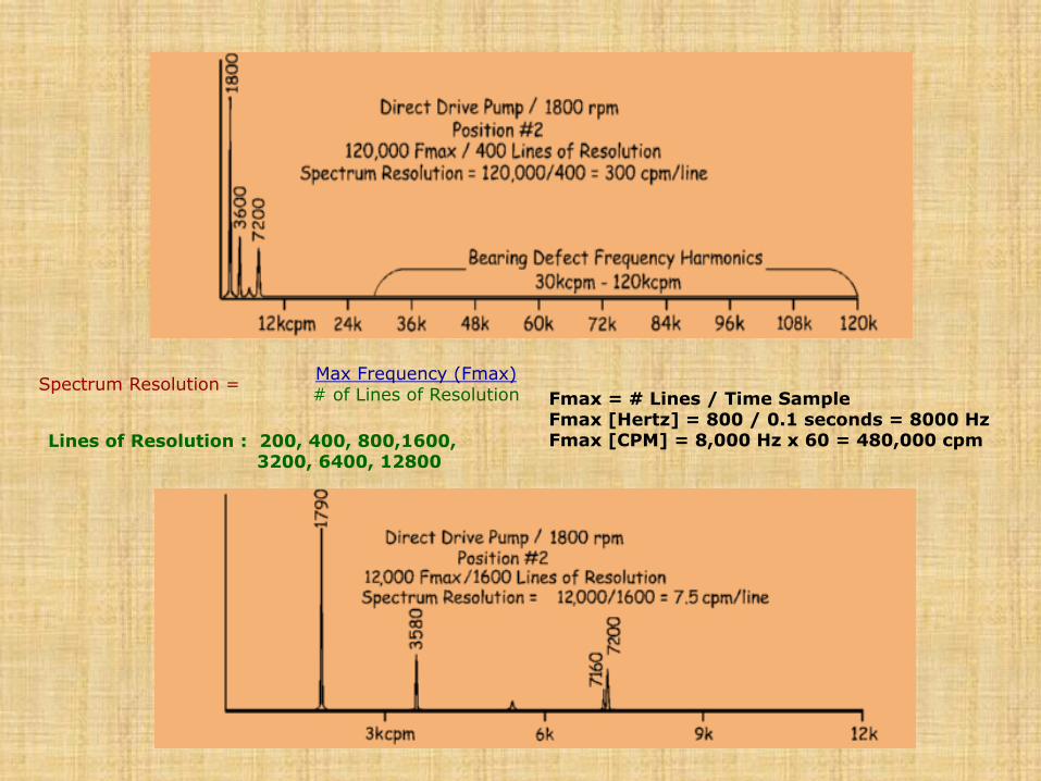
Lines of Resolution : 200, 400, 800,1600, 3200, 6400, 12800
Spectrum Resolution = Max Frequency (Fmax)
# of Lines of Resolution Fmax = # Lines / Time Sample Fmax [Hertz] = 800 / 0.1 seconds = 8000 Hz Fmax [CPM] = 8,000 Hz x 60 = 480,000 cpm
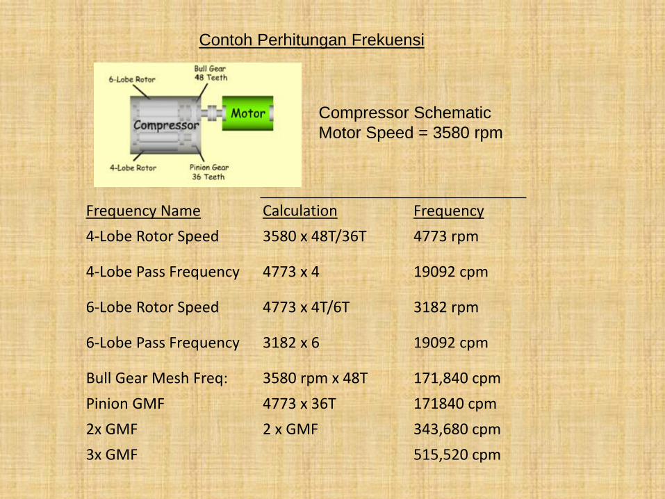
Frequency Name Calculation Frequency
4-Lobe Rotor Speed 3580 x 48T/36T 4773 rpm
4-Lobe Pass Frequency 4773 x 4 19092 cpm
6-Lobe Rotor Speed 4773 x 4T/6T 3182 rpm
6-Lobe Pass Frequency 3182 x 6 19092 cpm
Bull Gear Mesh Freq: 3580 rpm x 48T 171,840 cpm
Pinion GMF 4773 x 36T 171840 cpm
2x GMF 2 x GMF 343,680 cpm
3x GMF 515,520 cpm
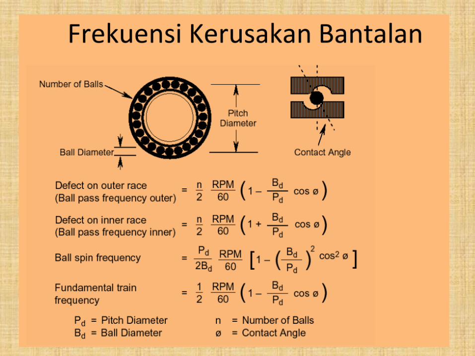
Contoh Perhitungan Frekuensi
Compressor Schematic
Motor Speed = 3580 rpm
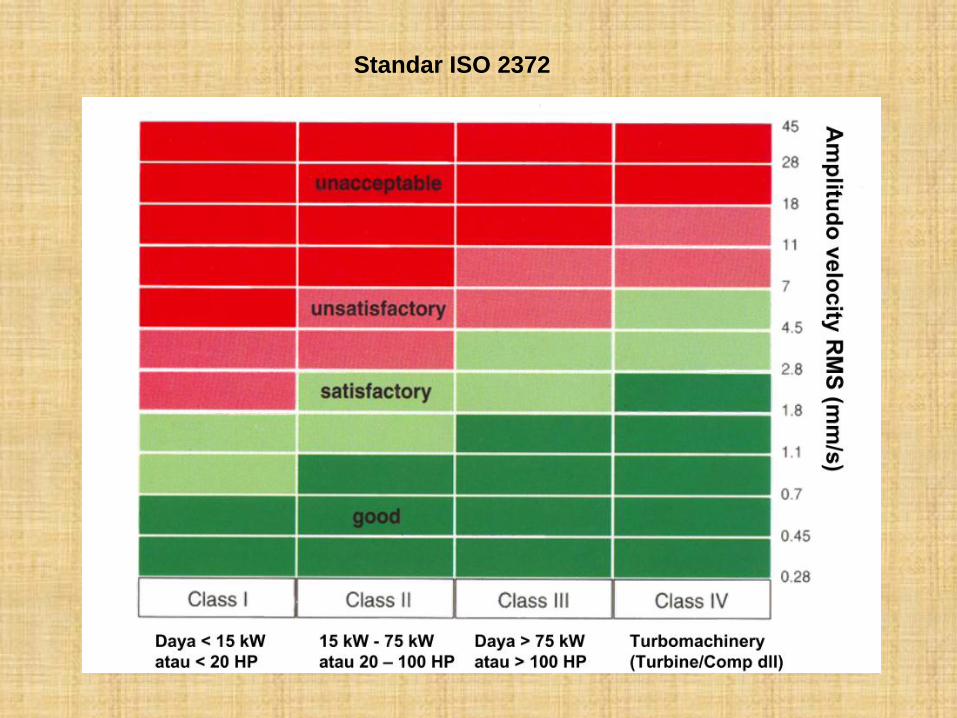
Standar ISO 2372
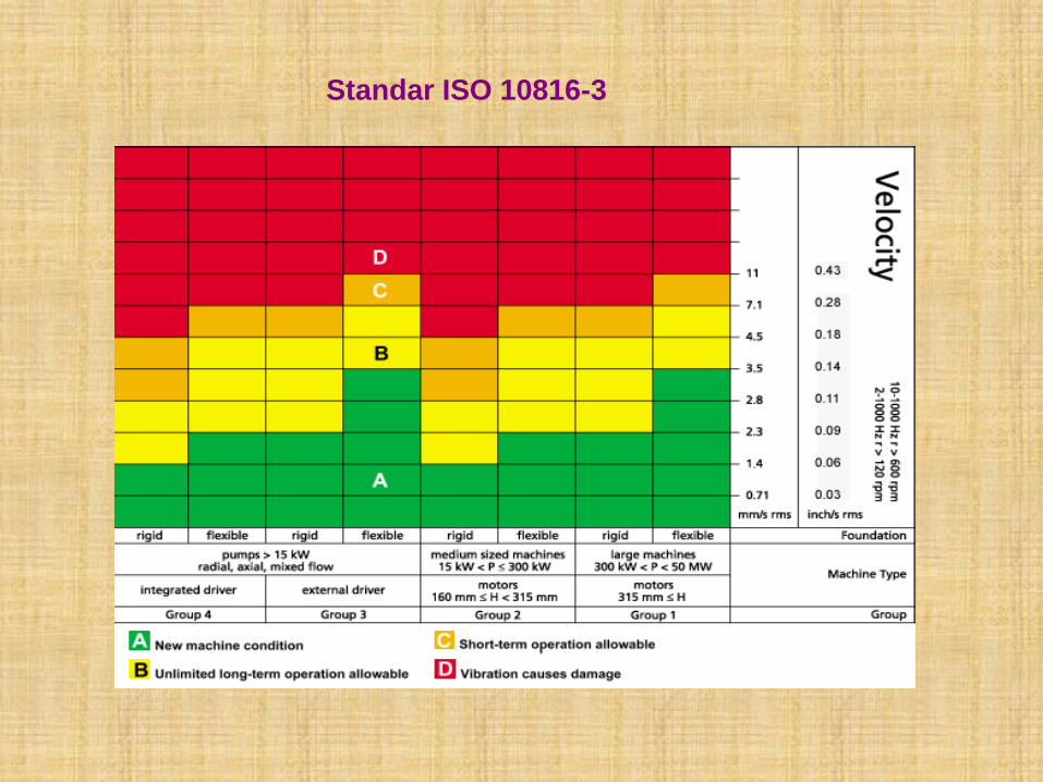
Standar ISO 10816-3
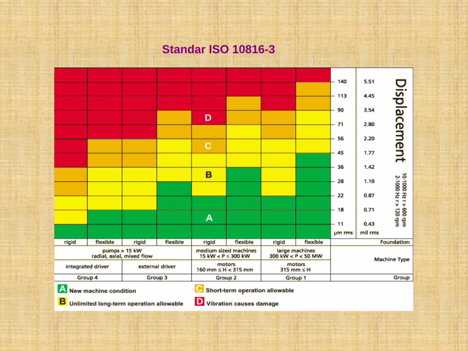
Standar ISO 10816-3
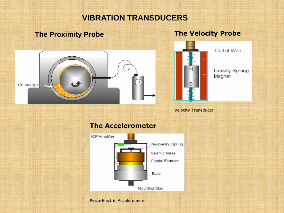
The Velocity Probe
Velocity Transducer
The Accelerometer
Piezo-Electric Accelerometer
The Proximity Probe
VIBRATION TRANSDUCERS
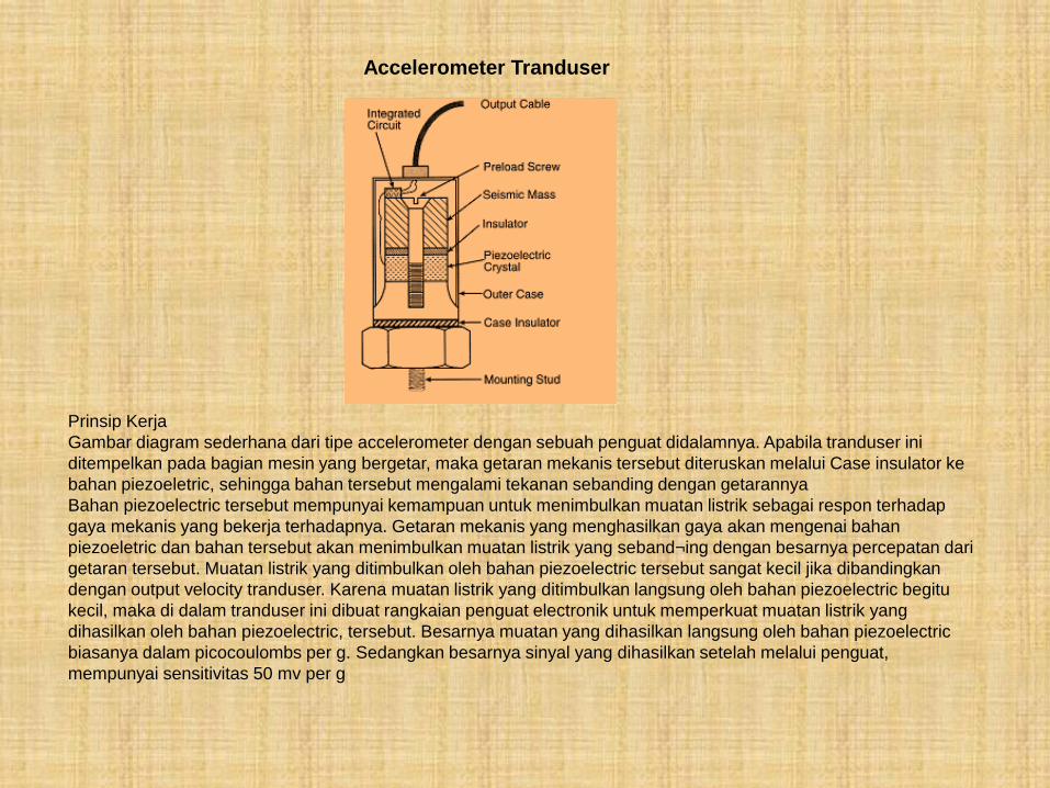
Accelerometer Tranduser
Prinsip Kerja
Gambar diagram sederhana dari tipe accelerometer dengan sebuah penguat didalamnya. Apabila tranduser ini
ditempelkan pada bagian mesin yang bergetar, maka getaran mekanis tersebut diteruskan melalui Case insulator ke
bahan piezoeletric, sehingga bahan tersebut mengalami tekanan sebanding dengan getarannya
Bahan piezoelectric tersebut mempunyai kemampuan untuk menimbulkan muatan listrik sebagai respon terhadap
gaya mekanis yang bekerja terhadapnya. Getaran mekanis yang menghasilkan gaya akan mengenai bahan
piezoeletric dan bahan tersebut akan menimbulkan muatan listrik yang seband¬ing dengan besarnya percepatan dari
getaran tersebut. Muatan listrik yang ditimbulkan oleh bahan piezoelectric tersebut sangat kecil jika dibandingkan
dengan output velocity tranduser. Karena muatan listrik yang ditimbulkan langsung oleh bahan piezoelectric begitu
kecil, maka di dalam tranduser ini dibuat rangkaian penguat electronik untuk memperkuat muatan listrik yang
dihasilkan oleh bahan piezoelectric, tersebut. Besarnya muatan yang dihasilkan langsung oleh bahan piezoelectric
biasanya dalam picocoulombs per g. Sedangkan besarnya sinyal yang dihasilkan setelah melalui penguat,
mempunyai sensitivitas 50 mv per g
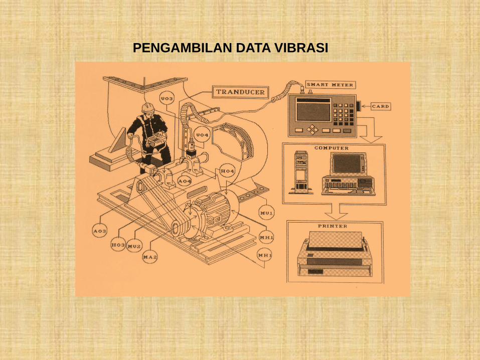
PENGAMBILAN DATA VIBRASI
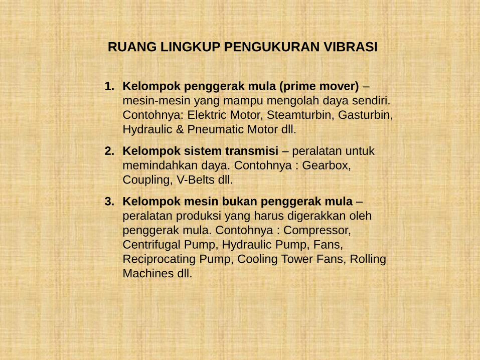
RUANG LINGKUP PENGUKURAN VIBRASI
1. Kelompok penggerak mula (prime mover) –
mesin-mesin yang mampu mengolah daya sendiri.
Contohnya: Elektric Motor, Steamturbin, Gasturbin,
Hydraulic & Pneumatic Motor dll.
2. Kelompok sistem transmisi – peralatan untuk
memindahkan daya. Contohnya : Gearbox,
Coupling, V-Belts dll.
3. Kelompok mesin bukan penggerak mula –
peralatan produksi yang harus digerakkan oleh
penggerak mula. Contohnya : Compressor,
Centrifugal Pump, Hydraulic Pump, Fans,
Reciprocating Pump, Cooling Tower Fans, Rolling
Machines dll.
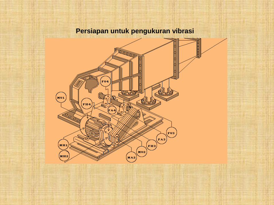
Persiapan untuk pengukuran vibrasi
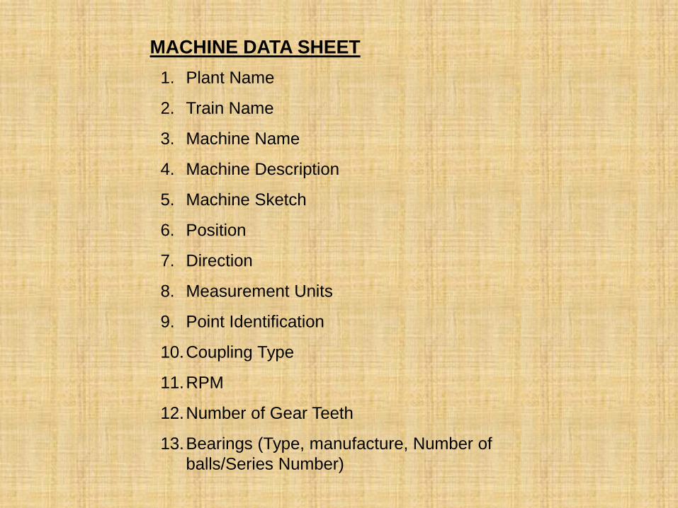
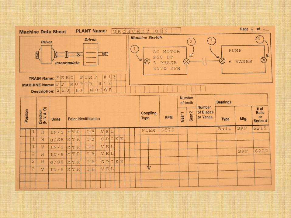
MACHINE DATA SHEET
1. Plant Name
2. Train Name
3. Machine Name
4. Machine Description
5. Machine Sketch
6. Position
7. Direction
8. Measurement Units
9. Point Identification
10.Coupling Type
11.RPM
12.Number of Gear Teeth
13.Bearings (Type, manufacture, Number of
balls/Series Number)
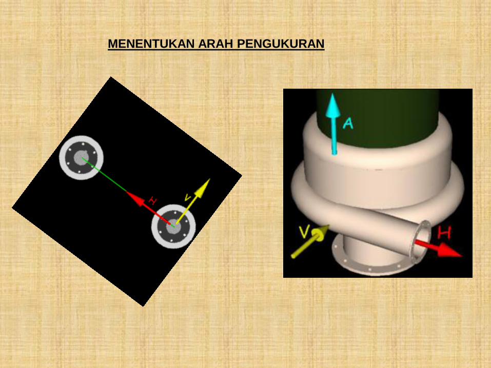
MENENTUKAN ARAH PENGUKURAN
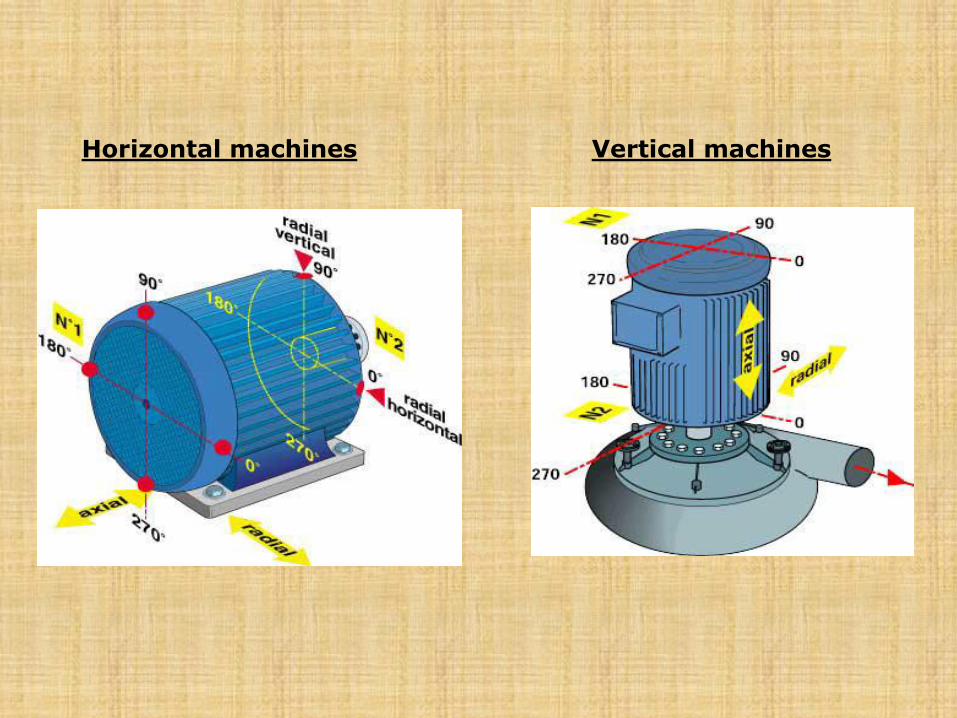
Horizontal machines Vertical machines
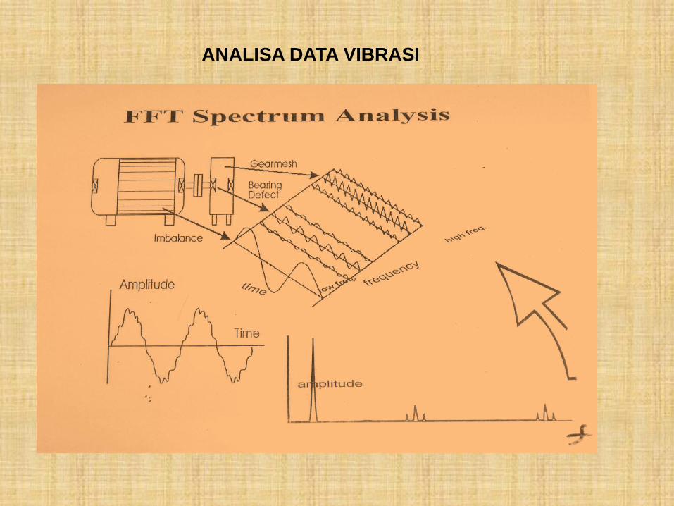
ANALISA DATA VIBRASI
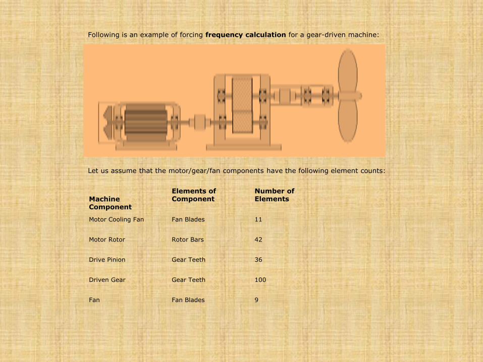
Following is an example of forcing frequency calculation for a gear-driven machine:
Let us assume that the motor/gear/fan components have the following element counts:
Machine Component
Elements of Component
Number of Elements
Motor Cooling Fan
Fan Blades
11
Motor Rotor
Rotor Bars
42
Drive Pinion
Gear Teeth
36
Driven Gear
Gear Teeth
100
Fan
Fan Blades
9
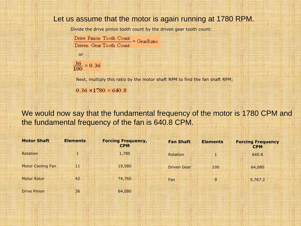
Let us assume that the motor is again running at 1780 RPM.
Divide the drive pinion tooth count by the driven gear tooth count:
or
Next, multiply this ratio by the motor shaft RPM to find the fan shaft RPM;
We would now say that the fundamental frequency of the motor is 1780 CPM and
the fundamental frequency of the fan is 640.8 CPM.
Motor Shaft Elements Forcing Frequency, CPM
Rotation
1
1,780
Motor Cooling Fan
11
19,580
Motor Rotor
42
74,760
Drive Pinion
36
64,080
Fan Shaft Elements Forcing Frequency CPM
Rotation
1
640.8
Driven Gear
100
64,080
Fan
9
5,767.2
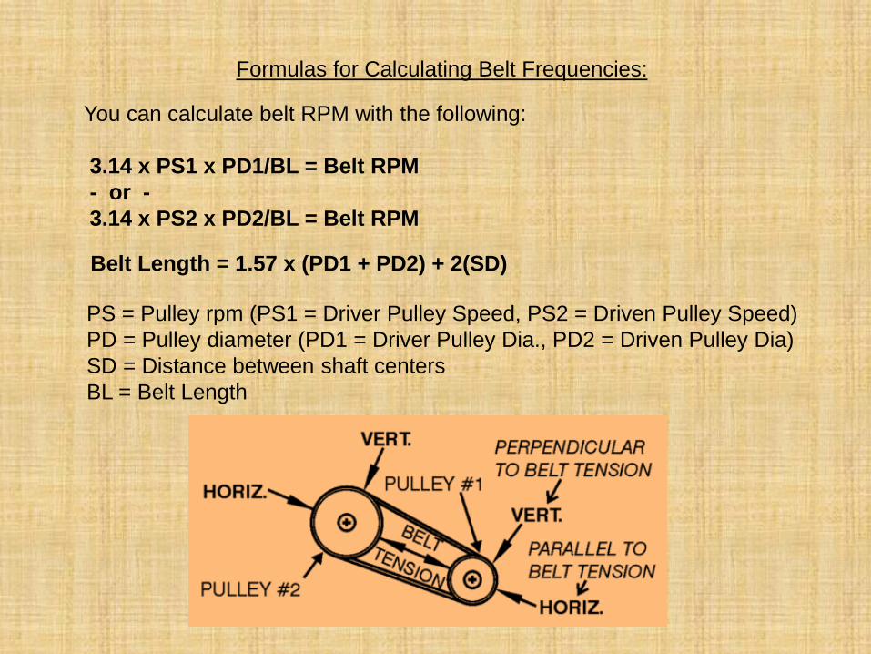
Formulas for Calculating Belt Frequencies:
You can calculate belt RPM with the following:
3.14 x PS1 x PD1/BL = Belt RPM
- or -
3.14 x PS2 x PD2/BL = Belt RPM
Belt Length = 1.57 x (PD1 + PD2) + 2(SD)
PS = Pulley rpm (PS1 = Driver Pulley Speed, PS2 = Driven Pulley Speed)
PD = Pulley diameter (PD1 = Driver Pulley Dia., PD2 = Driven Pulley Dia)
SD = Distance between shaft centers
BL = Belt Length
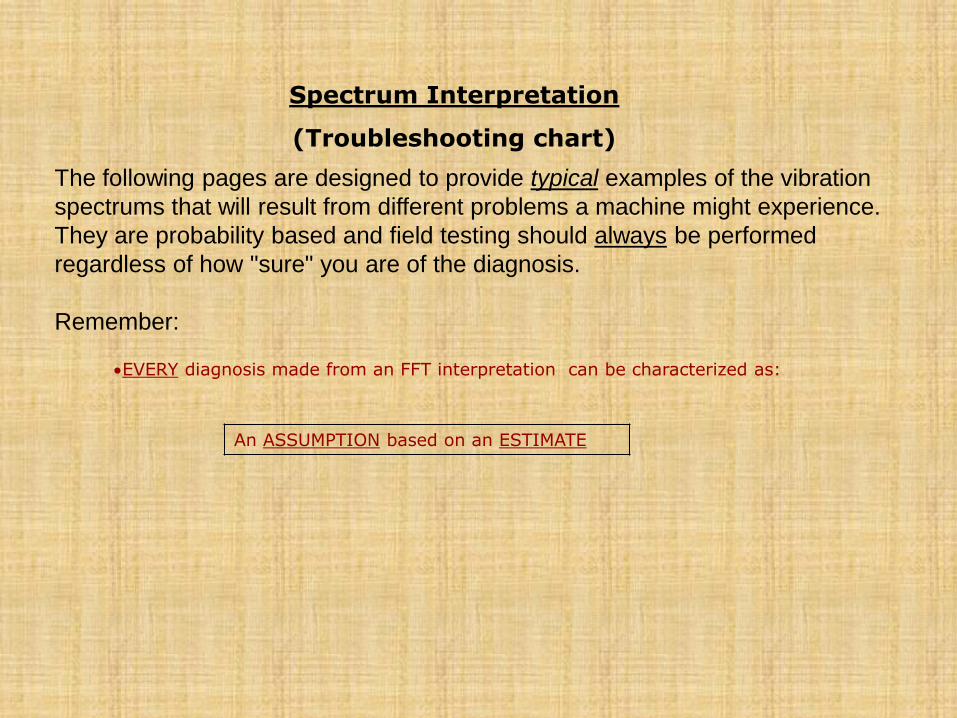
Spectrum Interpretation
(Troubleshooting chart)
The following pages are designed to provide typical examples of the vibration
spectrums that will result from different problems a machine might experience.
They are probability based and field testing should always be performed
regardless of how "sure" you are of the diagnosis.
Remember: EVERY diagnosis made from an FFT interpretation can be characterized as:
An ASSUMPTION based on an ESTIMATE
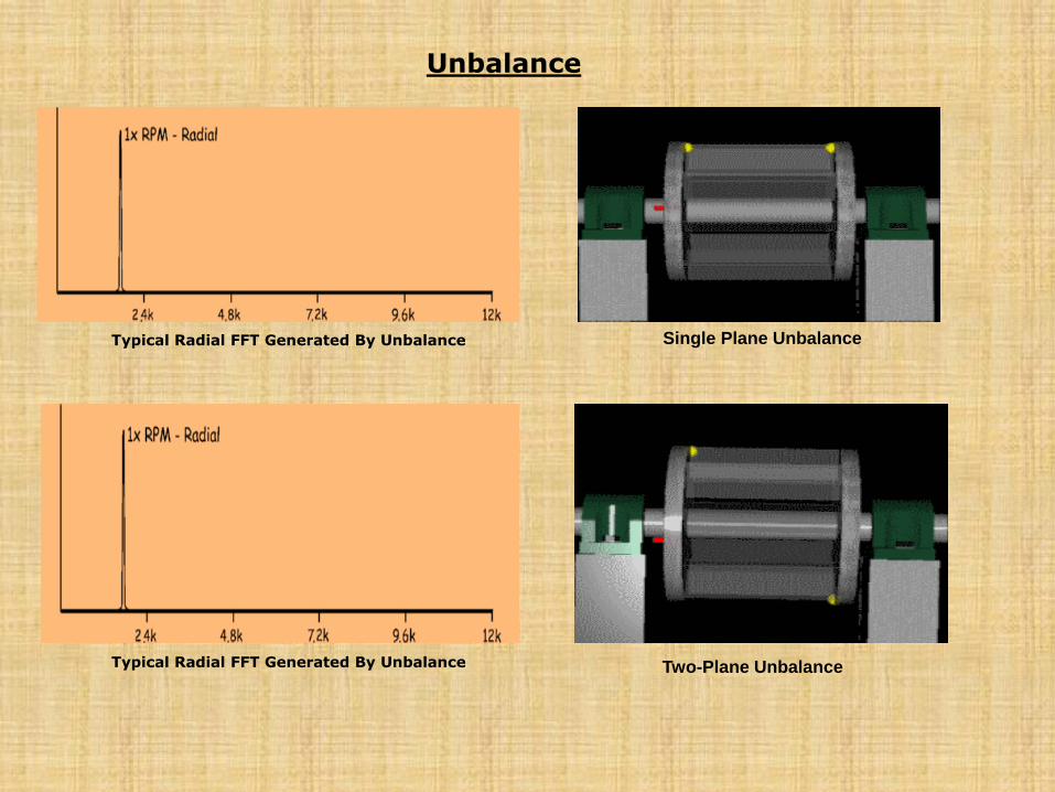
Typical Radial FFT Generated By Unbalance Single Plane Unbalance
Unbalance
Two-Plane Unbalance Typical Radial FFT Generated By Unbalance
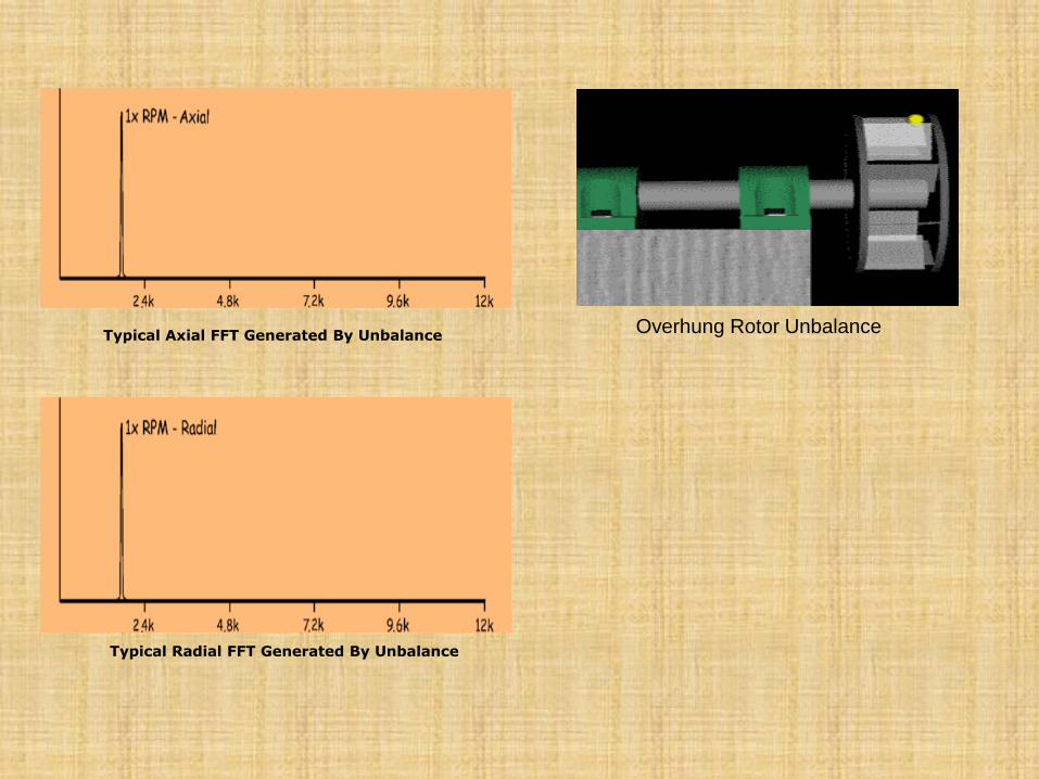
Typical Axial FFT Generated By Unbalance
Overhung Rotor Unbalance
Typical Radial FFT Generated By Unbalance
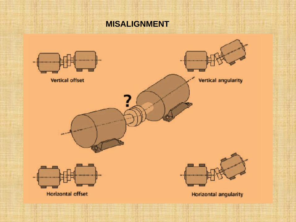
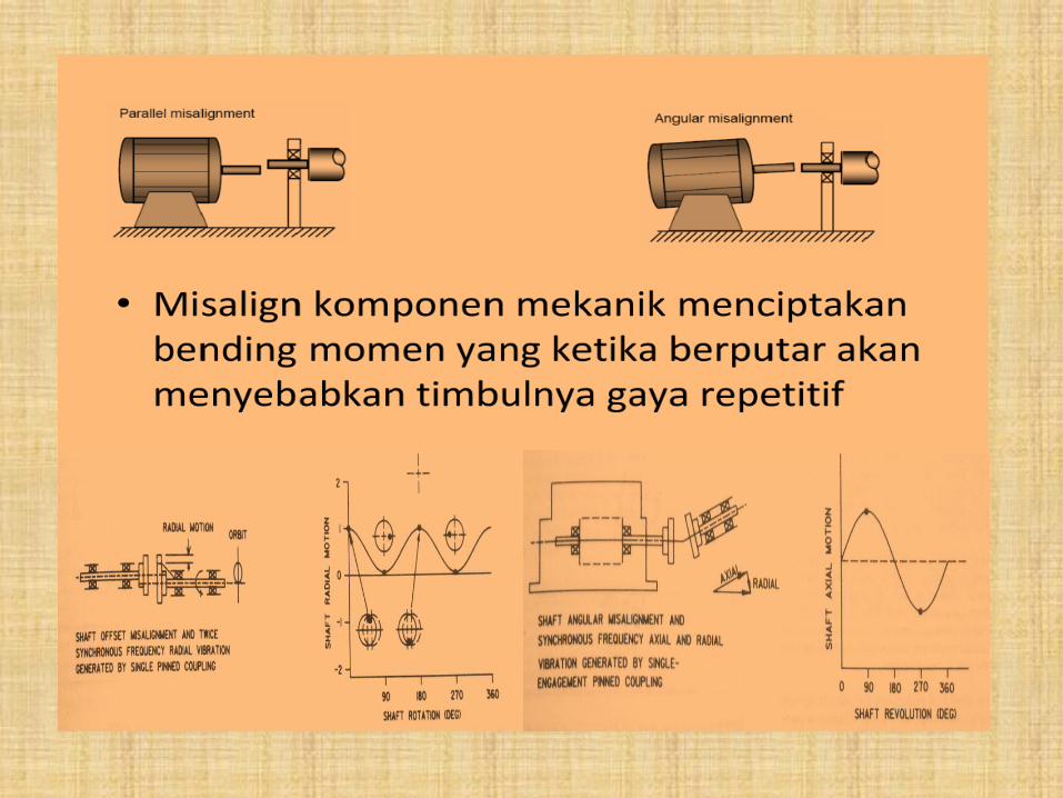
MISALIGNMENT
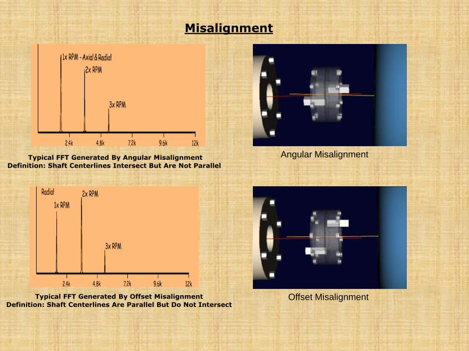
Typical FFT Generated By Angular Misalignment Definition: Shaft Centerlines Intersect But Are Not Parallel
Typical FFT Generated By Offset Misalignment Definition: Shaft Centerlines Are Parallel But Do Not Intersect
Angular Misalignment
Offset Misalignment
Misalignment
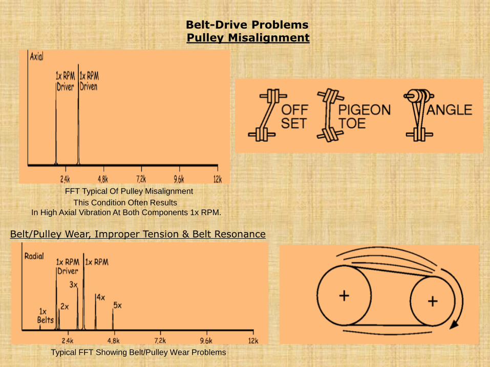
Belt-Drive Problems
Pulley Misalignment
FFT Typical Of Pulley Misalignment
This Condition Often Results
In High Axial Vibration At Both Components 1x RPM.
Belt/Pulley Wear, Improper Tension & Belt Resonance
Typical FFT Showing Belt/Pulley Wear Problems
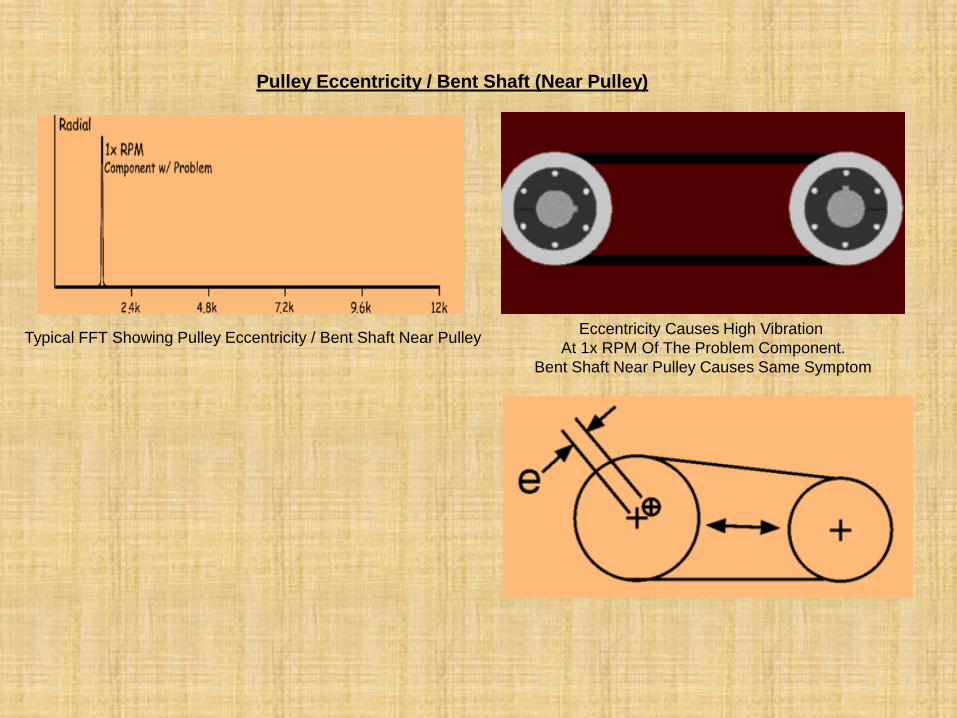
Pulley Eccentricity / Bent Shaft (Near Pulley)
Typical FFT Showing Pulley Eccentricity / Bent Shaft Near Pulley Eccentricity Causes High Vibration
At 1x RPM Of The Problem Component.
Bent Shaft Near Pulley Causes Same Symptom
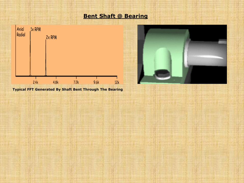
Typical FFT Generated By Shaft Bent Through The Bearing
Bent Shaft @ Bearing
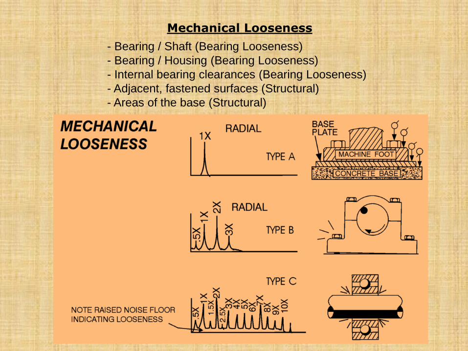
- Bearing / Shaft (Bearing Looseness)
- Bearing / Housing (Bearing Looseness)
- Internal bearing clearances (Bearing Looseness)
- Adjacent, fastened surfaces (Structural)
- Areas of the base (Structural)
Mechanical Looseness
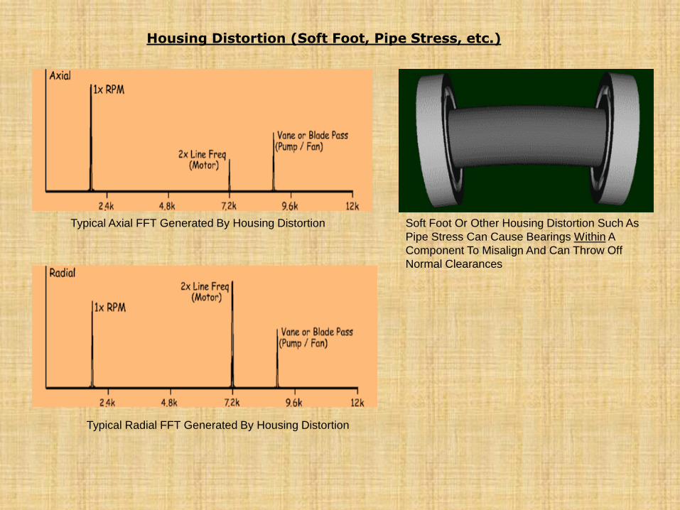
Housing Distortion (Soft Foot, Pipe Stress, etc.)
Typical Axial FFT Generated By Housing Distortion
Typical Radial FFT Generated By Housing Distortion
Soft Foot Or Other Housing Distortion Such As
Pipe Stress Can Cause Bearings Within A
Component To Misalign And Can Throw Off
Normal Clearances
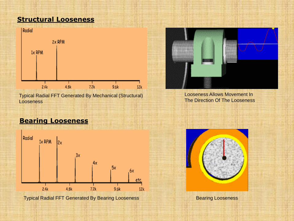
Structural Looseness
Typical Radial FFT Generated By Mechanical (Structural)
Looseness
Looseness Allows Movement In
The Direction Of The Looseness
Bearing Looseness
Typical Radial FFT Generated By Bearing Looseness Bearing Looseness
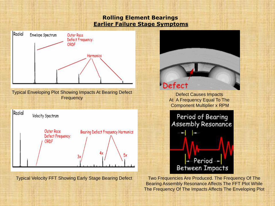
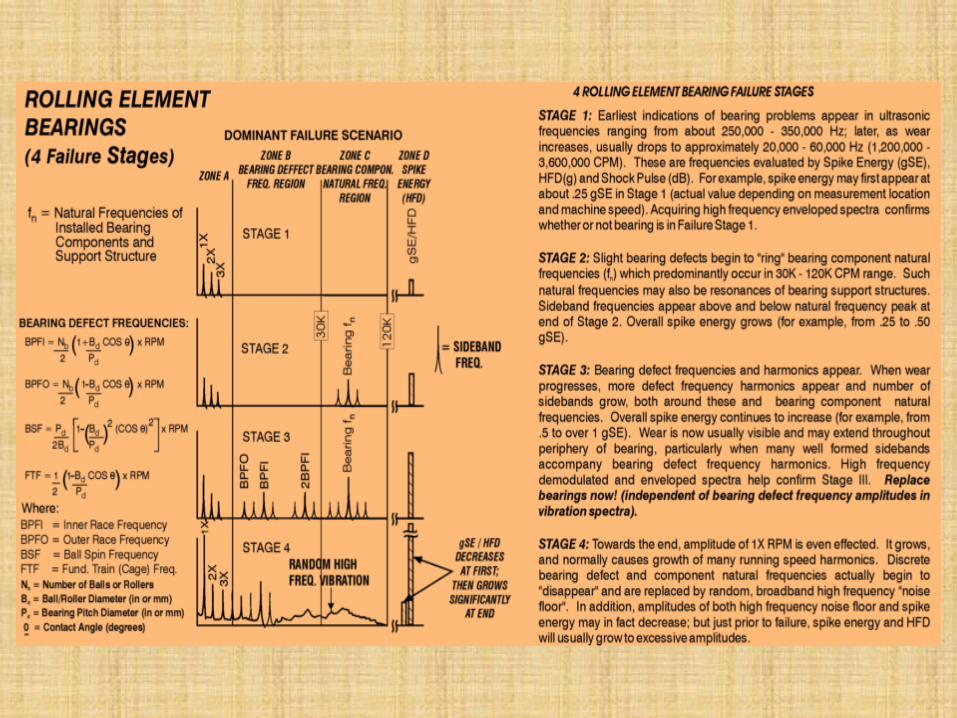
Rolling Element Bearings
Earlier Failure Stage Symptoms
Typical Enveloping Plot Showing Impacts At Bearing Defect
Frequency
Typical Velocity FFT Showing Early Stage Bearing Defect
Defect Causes Impacts
At A Frequency Equal To The
Component Multiplier x RPM
Two Frequencies Are Produced. The Frequency Of The
Bearing Assembly Resonance Affects The FFT Plot While
The Frequency Of The Impacts Affects The Enveloping Plot
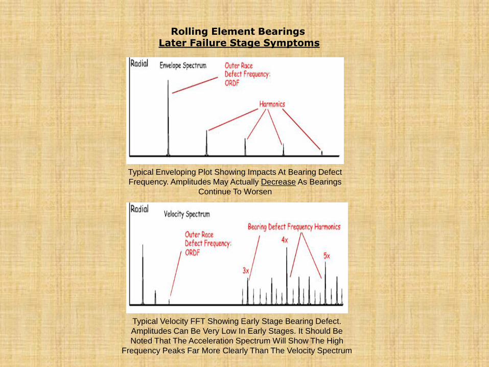
Rolling Element Bearings
Later Failure Stage Symptoms
Typical Enveloping Plot Showing Impacts At Bearing Defect
Frequency. Amplitudes May Actually Decrease As Bearings
Continue To Worsen
Typical Velocity FFT Showing Early Stage Bearing Defect.
Amplitudes Can Be Very Low In Early Stages. It Should Be
Noted That The Acceleration Spectrum Will Show The High
Frequency Peaks Far More Clearly Than The Velocity Spectrum
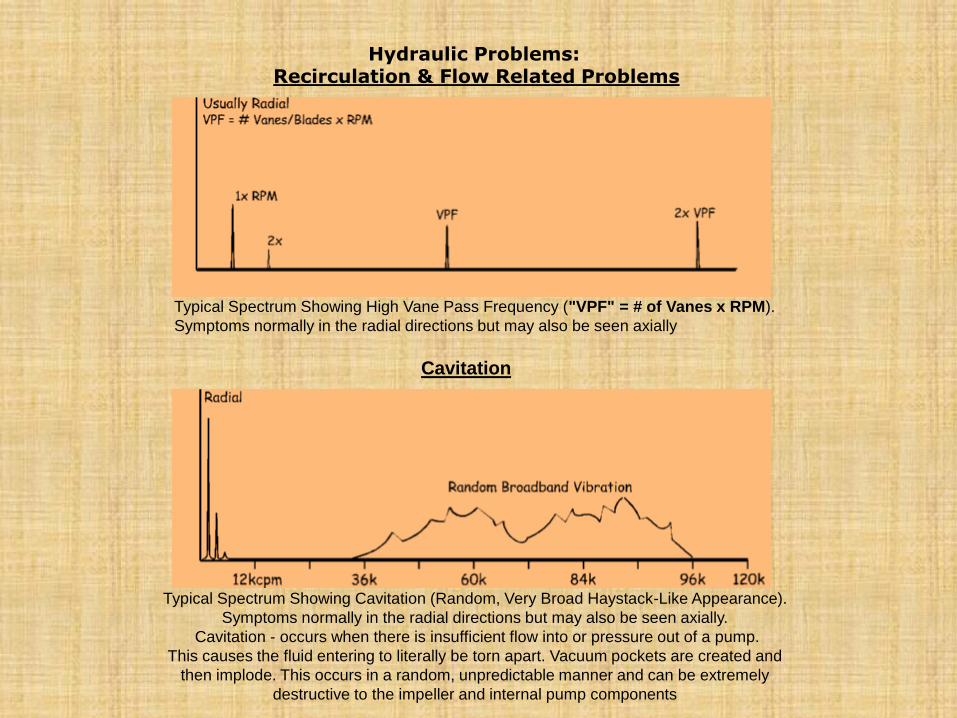
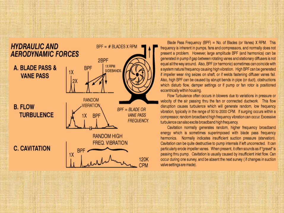
Hydraulic Problems: Recirculation & Flow Related Problems
Typical Spectrum Showing High Vane Pass Frequency ("VPF" = # of Vanes x RPM).
Symptoms normally in the radial directions but may also be seen axially
Cavitation
Typical Spectrum Showing Cavitation (Random, Very Broad Haystack-Like Appearance).
Symptoms normally in the radial directions but may also be seen axially.
Cavitation - occurs when there is insufficient flow into or pressure out of a pump.
This causes the fluid entering to literally be torn apart. Vacuum pockets are created and
then implode. This occurs in a random, unpredictable manner and can be extremely
destructive to the impeller and internal pump components
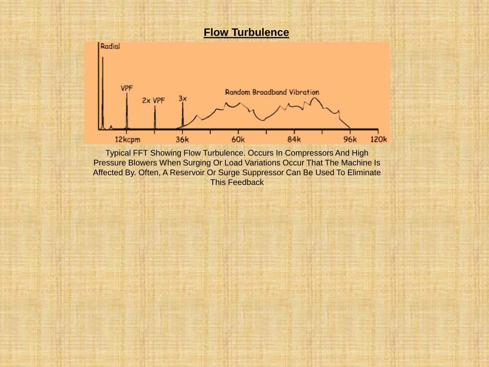
Flow Turbulence
Typical FFT Showing Flow Turbulence. Occurs In Compressors And High
Pressure Blowers When Surging Or Load Variations Occur That The Machine Is
Affected By. Often, A Reservoir Or Surge Suppressor Can Be Used To Eliminate
This Feedback
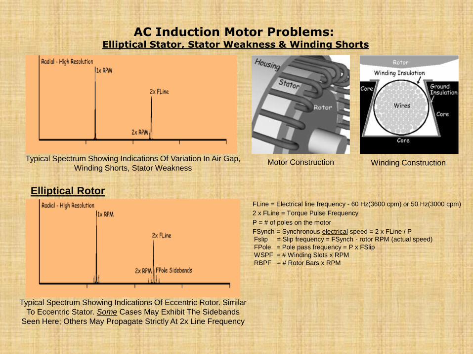
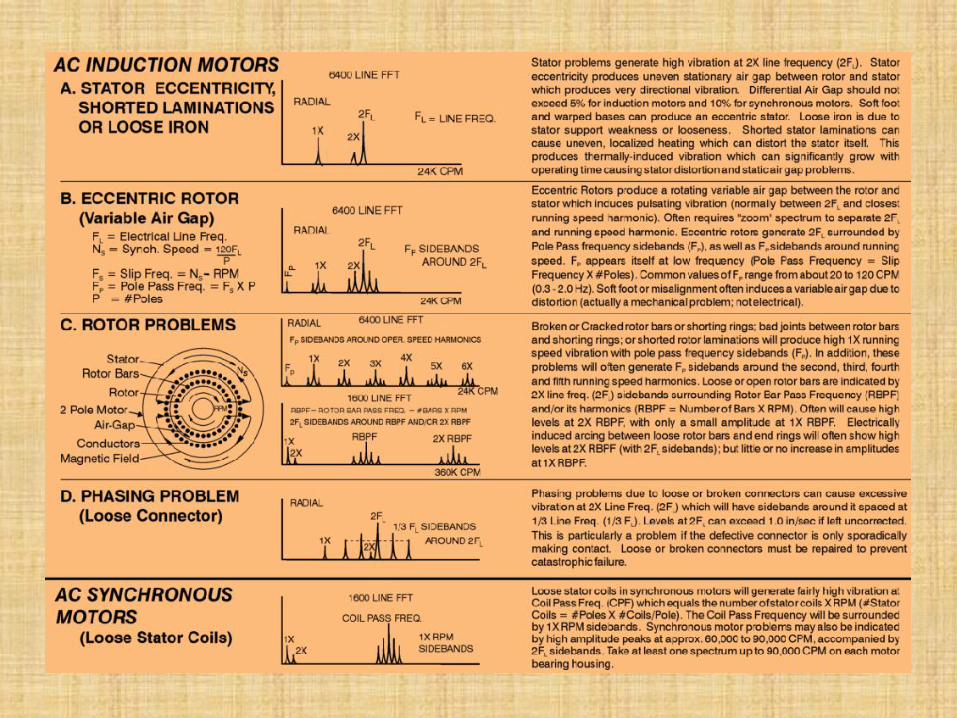
AC Induction Motor Problems: Elliptical Stator, Stator Weakness & Winding Shorts
Typical Spectrum Showing Indications Of Variation In Air Gap,
Winding Shorts, Stator Weakness
Elliptical Rotor
Typical Spectrum Showing Indications Of Eccentric Rotor. Similar
To Eccentric Stator. Some Cases May Exhibit The Sidebands
Seen Here; Others May Propagate Strictly At 2x Line Frequency
Motor Construction Winding Construction
FLine = Electrical line frequency - 60 Hz(3600 cpm) or 50 Hz(3000 cpm)
2 x FLine = Torque Pulse Frequency
P = # of poles on the motor
FSynch = Synchronous electrical speed = 2 x FLine / P
Fslip = Slip frequency = FSynch - rotor RPM (actual speed)
FPole = Pole pass frequency = P x FSlip
WSPF = # Winding Slots x RPM
RBPF = # Rotor Bars x RPM
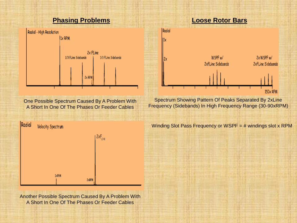
Phasing Problems
One Possible Spectrum Caused By A Problem With
A Short In One Of The Phases Or Feeder Cables
Another Possible Spectrum Caused By A Problem With
A Short In One Of The Phases Or Feeder Cables
Loose Rotor Bars
Spectrum Showing Pattern Of Peaks Separated By 2xLine
Frequency (Sidebands) In High Frequency Range (30-90xRPM)
Winding Slot Pass Frequency or WSPF = # windings slot x RPM
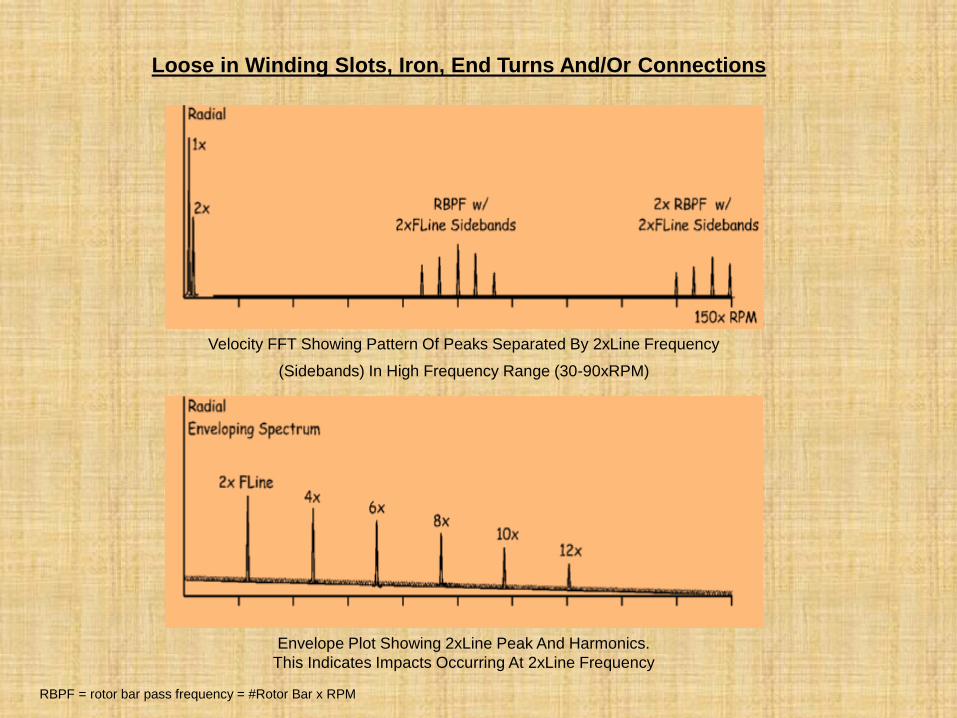
Loose in Winding Slots, Iron, End Turns And/Or Connections
Velocity FFT Showing Pattern Of Peaks Separated By 2xLine Frequency
(Sidebands) In High Frequency Range (30-90xRPM)
Envelope Plot Showing 2xLine Peak And Harmonics.
This Indicates Impacts Occurring At 2xLine Frequency
RBPF = rotor bar pass frequency = #Rotor Bar x RPM
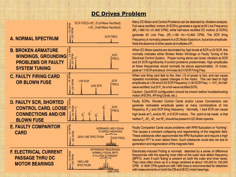
DC Drives Problem
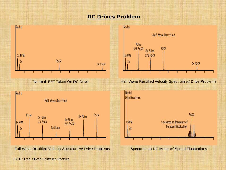
DC Drives Problem
"Normal" FFT Taken On DC Drive
Full-Wave Rectified Velocity Spectrum w/ Drive Problems
Half-Wave Rectified Velocity Spectrum w/ Drive Problems
Spectrum on DC Motor w/ Speed Fluctuations
FSCR : Freq. Silicon Controlled Rectifier
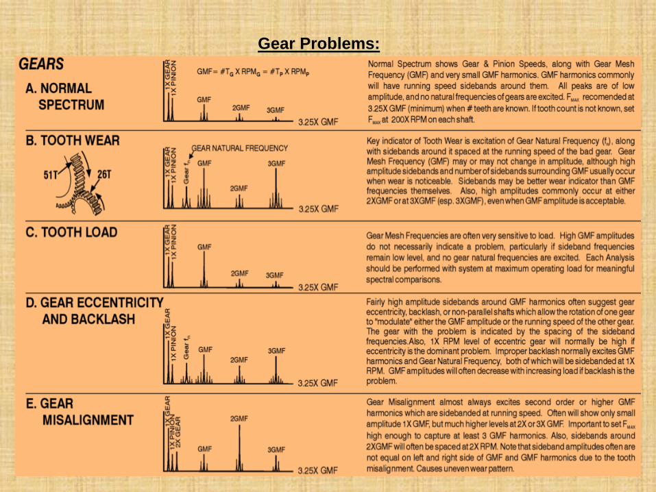
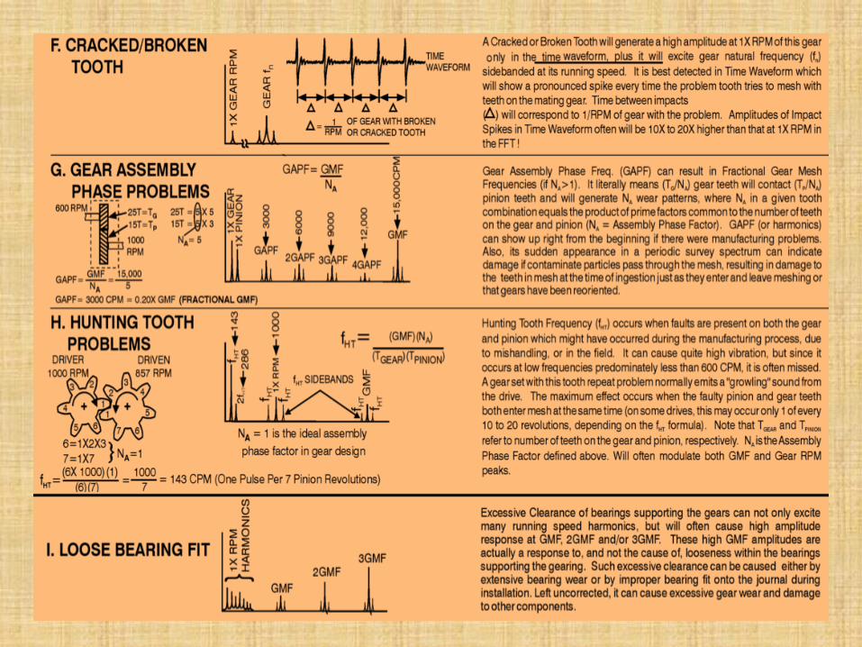
Gear Problems:
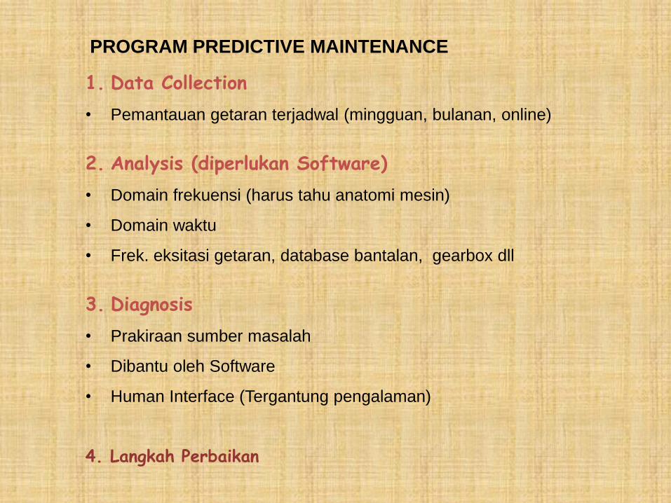
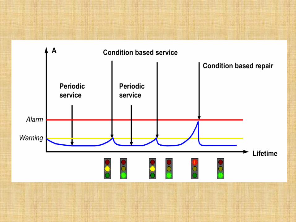
PROGRAM PREDICTIVE MAINTENANCE
1. Data Collection
• Pemantauan getaran terjadwal (mingguan, bulanan, online)
2. Analysis (diperlukan Software)
• Domain frekuensi (harus tahu anatomi mesin)
• Domain waktu
• Frek. eksitasi getaran, database bantalan, gearbox dll
3. Diagnosis
• Prakiraan sumber masalah
• Dibantu oleh Software
• Human Interface (Tergantung pengalaman)
4. Langkah Perbaikan
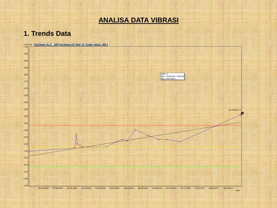
ANALISA DATA VIBRASI
1. Trends Data
20/ 07/ 2009 07/ 09/ 2009 26/ 10/ 2009 14/ 12/ 2009 01/ 02/ 2010 22/ 03/ 2010 10/ 05/ 2010 28/ 06/ 2010 16/ 08/ 2010 04/ 10/ 2010 22/ 11/ 2010 10/ 01/ 2011 28/ 02/ 2011 18/ 04/ 2011
0,00
0,05
0,10
0,15
0,20
0,25
0,30
0,35
0,40
0,45
0,50
0,55
0,60
0,65
0,70
0,75
0,80
0,85
0,90
0,95
1,00
Fan/ blower No.21 - ARP\ Fan/ blower # 21\ BA4\ 101 Ov erall v eloc ity >600
M
(01/ 06/ 2011 19:06:29 / 0,51)
date
v [inch/ s]
RPM : 0
M(x) : 01/ 06/ 2011 19:06:29
M(y) : 0,51 inch/ s
0 1000 2000 3000 4000 5000 6000 7000 8000 9000 10000 11000 12000 13000 14000 15000 16000 17000 18000 19000 20000 21000 22000 23000 24000
0,00
0,02
0,04
0,06
0,08
0,10
0,12
0,14
0,16
0,18
0,20
0,22
0,24
0,26
0,28
0,30
0,32
0,34
0,36
0,38
0,40
0,42
0,44
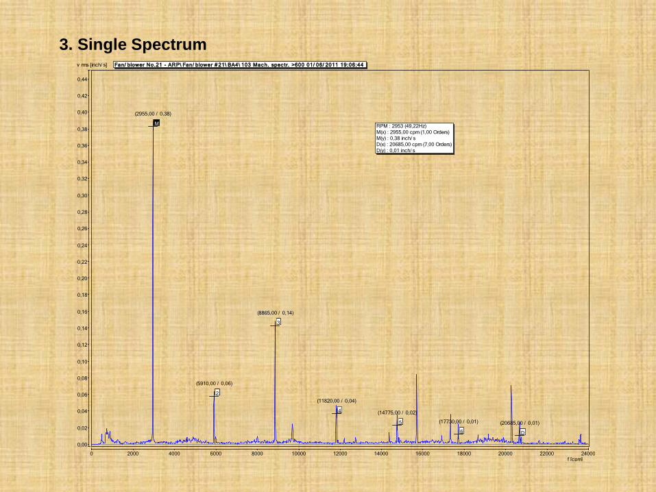
Fan/ blower No.21 - ARP\ Fan/ blower # 21\ BA4\ 103 Mac h. spec tr. >600 01/ 06/ 2011 19:06:44
01/ 06/ 2011
03/ 11/ 2010
19/ 09/ 2010
24/ 08/ 2010
17/ 07/ 2010
02/ 06/ 2010
04/ 05/ 2010
16/ 04/ 2010
M
(2955,00 / 0,38)
f [cpm]
v rms [inch/ s]
RPM : 2953 (49,22Hz)
M(x) : 2955,00 cpm (1,00 Orders)
M(y) : 0,38 inch/ s
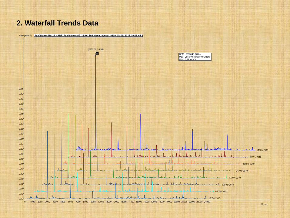
2. Waterfall Trends Data
0 2000 4000 6000 8000 10000 12000 14000 16000 18000 20000 22000 24000
0,00
0,02
0,04
0,06
0,08
0,10
0,12
0,14
0,16
0,18
0,20
0,22
0,24
0,26
0,28
0,30
0,32
0,34
0,36
0,38
0,40
0,42
0,44
Fan/ blower No.21 - ARP\ Fan/ blower # 21\ BA4\ 103 Mac h. spec tr. >600 01/ 06/ 2011 19:06:44
2
(5910,00 / 0,06)
3
(8865,00 / 0,14)
4
(11820,00 / 0,04)
5
(14775,00 / 0,02)
6
(17730,00 / 0,01)
D
(20685,00 / 0,01)
M
(2955,00 / 0,38)
f [cpm]
v rms [inch/ s]
RPM : 2953 (49,22Hz)
M(x) : 2955,00 cpm (1,00 Orders)
M(y) : 0,38 inch/ s
D(x) : 20685,00 cpm (7,00 Orders)
D(y) : 0,01 inch/ s
3. Single Spectrum
0 2000 4000 6000 8000 10000 12000 14000 16000 18000 20000 22000 24000 26000 28000 30000 32000 34000 36000
0,00
0,05
0,10
0,15
0,20
0,25
0,30
0,35
0,40
0,45
0,50
0,55
0,60
0,65
0,70
0,75
0,80
0,85
0,90
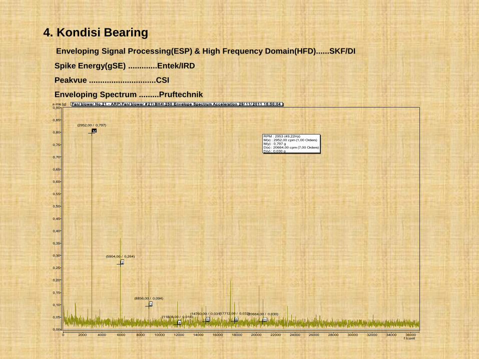
Fan/ blower No.21 - ARP\ Fan/ blower # 21\ BH4\ 250 Env elope Spec trum Ac c eleration 29/ 11/ 2011 16:50:04
2
(5904,00 / 0,264)
3
(8856,00 / 0,094)
4
(11808,00 / 0,018)5
(14760,00 / 0,031)
6
(17712,00 / 0,033)
D
(20664,00 / 0,030)
M
(2952,00 / 0,797)
f [cpm]
a rms [g]
RPM : 2953 (49,22Hz)
M(x) : 2952,00 cpm (1,00 Orders)
M(y) : 0,797 g
D(x) : 20664,00 cpm (7,00 Orders)
D(y) : 0,030 g
4. Kondisi Bearing
Enveloping Signal Processing(ESP) & High Frequency Domain(HFD)......SKF/DI
Spike Energy(gSE) .............Entek/IRD
Peakvue ..............................CSI
Enveloping Spectrum .........Pruftechnik
0 20 40 60 80 100 120 140 160 180 200 220 240 260 280 300 320 340 360 380 400 420 440 460 480 500
-0,70
-0,65
-0,60
-0,55
-0,50
-0,45
-0,40
-0,35
-0,30
-0,25
-0,20
-0,15
-0,10
-0,05
0,00
0,05
0,10
0,15
0,20
0,25
0,30
0,35
0,40
0,45
0,50
0,55
0,60
0,65
0,70
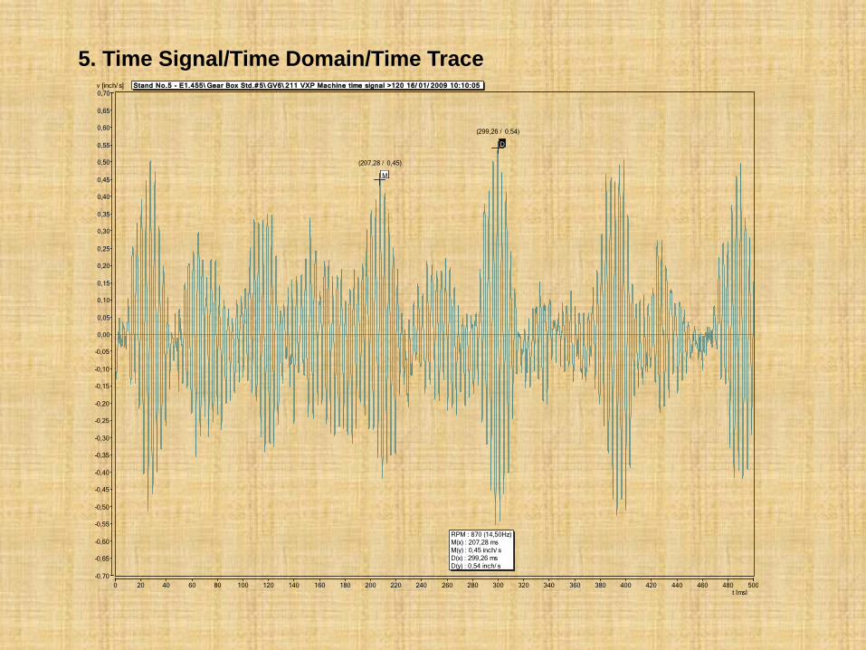
Stand No.5 - E1.455\ Gear Box Std.# 5\ GV6\ 211 VXP Mac hine t ime signal >120 16/ 01/ 2009 10:10:05
D
(299,26 / 0,54)
M
(207,28 / 0,45)
t [ms]
v [inch/ s]
RPM : 870 (14,50Hz)
M(x) : 207,28 ms
M(y) : 0,45 inch/ s
D(x) : 299,26 ms
D(y) : 0,54 inch/ s
5. Time Signal/Time Domain/Time Trace
-0,040 -0,035 -0,030 -0,025 -0,020 -0,015 -0,010 -0,005 0,000 0,005 0,010 0,015 0,020 0,025 0,030 0,035 0,040
90°
270°
-0,040
-0,038
-0,036
-0,034
-0,032
-0,030
-0,028
-0,026
-0,024
-0,022
-0,020
-0,018
-0,016
-0,014
-0,012
-0,010
-0,008
-0,006
-0,004
-0,002
0,000
0,002
0,004
0,006
0,008
0,010
0,012
0,014
0,016
0,018
0,020
0,022
0,024
0,026
0,028
0,030
0,032
0,034
0,036
0,038
0,040
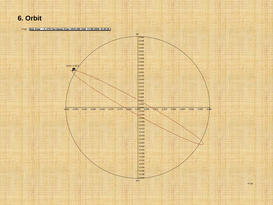
Strip Dryer - J1.470\ Fan/ blower Dryer \ BV3\ 285 Orbit 17/ 06/ 2009 18:35:06
M
(-0,04 / 0,021)
Y1 [g]
Y2 [g]
6. Orbit
0 10 20 30 40 50 60 70 80 90 100 110 120 130 140 150 160 170 180 190 200 210 220 230 240 250 260 270 280 290 300 310 320 330 340 350
-0,050
-0,045
-0,040
-0,035
-0,030
-0,025
-0,020
-0,015
-0,010
-0,005
0,000
0,005
0,010
0,015
0,020
0,025
0,030
0,035
0,040
0,045
0,050
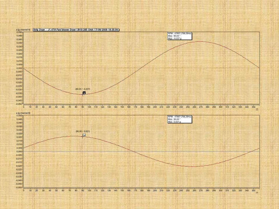
Strip Dryer - J1.470\ Fan/ blower Dryer \ BV3\ 285 Orbit 17/ 06/ 2009 18:35:06
M
(90,00 / -0,037)
[°]
a [g channel A]
RPM : 47897 (798,29Hz)
M(x) : 90,00 °
M(y) : -0,037 g
0 10 20 30 40 50 60 70 80 90 100 110 120 130 140 150 160 170 180 190 200 210 220 230 240 250 260 270 280 290 300 310 320 330 340 350
-0,050
-0,045
-0,040
-0,035
-0,030
-0,025
-0,020
-0,015
-0,010
-0,005
0,000
0,005
0,010
0,015
0,020
0,025
0,030
0,035
0,040
0,045
0,050
M
(90,00 / 0,021)
[°]
a [g channel B]
RPM : 47897 (798,29Hz)
M(x) : 90,00 °
M(y) : 0,021 g
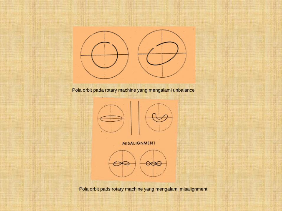
Pola orbit pada rotary machine yang mengalami unbalance
Pola orbit pads rotary machine yang mengalami misalignment
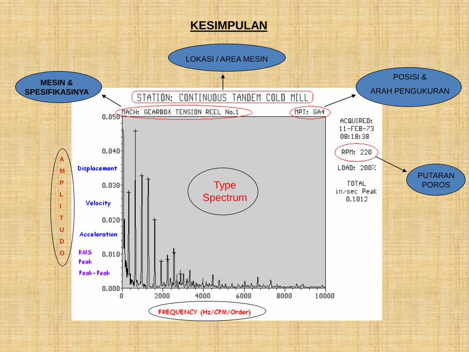
A
M
P
L
I
T
U
D
O
MESIN &
SPESIFIKASINYA
POSISI &
ARAH PENGUKURAN
LOKASI / AREA MESIN
PUTARAN
POROS
KESIMPULAN
Type
Spectrum

TERIMA KASIH