Embed Size (px)
Citation preview
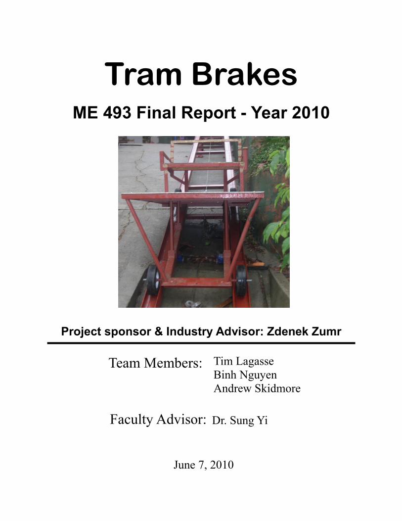
Tram Brakes ME 493 Final Report - Year 2010
Team Members:
Faculty Advisor:
June 7, 2010
Project sponsor & Industry Advisor: Zdenek Zumr
Tim Lagasse
Binh Nguyen
Andrew Skidmore
Dr. Sung Yi

Executive Summary
The project sponsor, Zdenek Zumr, operates a funicular tram at his residence.
The tram was intended to haul people and cargo up the steep slope to the residence. The
tram operates on a single pull cable and at the inception of this project had no means of
controlling the cart should the pull cable break or the winch malfunction. An emergency
braking system is required to keep people and cargo safe in the event of a cable or winch
malfunction.
The goal of this project is to provide an emergency braking system for the tram
cart that will activate automatically in the event of a cable or winch malfunction. The
braking system will stop the descent of the cart automatically and allow for a manual,
controlled descent to be performed by an occupant of the cart if needed. The braking
system must be reliable, be able to operate after long periods of non use, and operate
without destruction of major braking system components when used.
The Product Design Specifications were established by early February, and
detailed design was completed by late April. Prototype production took place during
May, with installation and testing occurring in late May. Documentation, including bill
of materials (BOM), operating and maintenance instructions (O&M), and assembly
drawings are ready to be delivered to the project sponsor. A final presentation was given
on June 2nd
, and this Final Report is due June 7th
, 2010.
The external search conducted by the design team used the internet and an on-site
visit to the Portland Aerial Tram to aid in producing concepts during the design team’s
internal search and concept brainstorming processes.
The internal search process produced seven feasible concepts. These concepts fall
into 3 basic categories: direct cable friction systems, brakes on a solid member, and
brakes controlling the rotational motion of a shaft with rotation caused by an independent
cable looped around a pulley connected to the shaft.
The concept in which a brake caliper applies braking force directly to a secondary
cable was selected. A provision for manual operation of the caliper by an occupant of the
tram cart was added to the system to satisfy the project sponsors requirements.
The braking system was completed using less than $ 300.00 of the $ 1,000.00
budget, was tested on schedule, and the project sponsor has agreed that all design
specifications have been met.

Table of Contents Introduction………..…………………………………………………. 1 Mission Statement…………………………………………………… 2 Main Design Requirements………………………………………… 2 Top Level Design Alternatives…………………………………….. 2 Final Product Design…...…………………………………………… 4 The Caliper Assembly……….……………………………………. 5 The Caliper Activation Assembly..……………………………... 9 Cable Guides……………………………………………………….. 12 Final Product Evaluation…………………………………………… 15 Appendix A: Detailed Description of Design, Manufacturing,
and Assembly………………………………………… A-1 Caliper Assembly…………………………………………………. A-1 Caliper Activation Assembly……………………………………. A-4 Spring Force Assembly…………………………………………… A-9 Secondary Cable Routing………………………………………... A-11 Final Assembly………………………………………………..…… A-15 Appendix B: Analysis……………………………………………….. B-1 Pillow Block Bolts Failure Analysis……………………………. B-1 Caliper Activation Lever Failure Analysis…………………….. B-3 Caliper Activation Tabs Failure Analysis……………………… B-6 Caliper Activation Shaft Failure Analysis………………...…… B-8 Brake Cable Failure Analysis……………………………………. B-11 Connecting Rod Failure Analysis………………………………. B-13 Force applied to braking cable versus time to stop cart…… B-15 References………………………………………………………….. B-19 Appendix C: Experiments………………………………………….. C-1 Caliper Force Evaluation Experiment………………………….. C-1 Appendix D: Bill of Materials………………………………………..D-1 Appendix E: Operation & Maintenance Manual………………… E-1 Operation Manual………………………………………………….. E-1 Maintenance Manual………………………………………………. E-1 Appendix F: Project Plan…………………………………………… F-1 Appendix G: Product Design Specifiaction…………………….. G-1 Appendix H: Suggested Bolt Tightening Torque………………. H-1 Appendix I: Expense Report……………………………………….. I-1 Appendix J: Approval & Project Handover Letter……………... J-1 Appendix K: Production Drawings……………………………….. K-1
Introduction
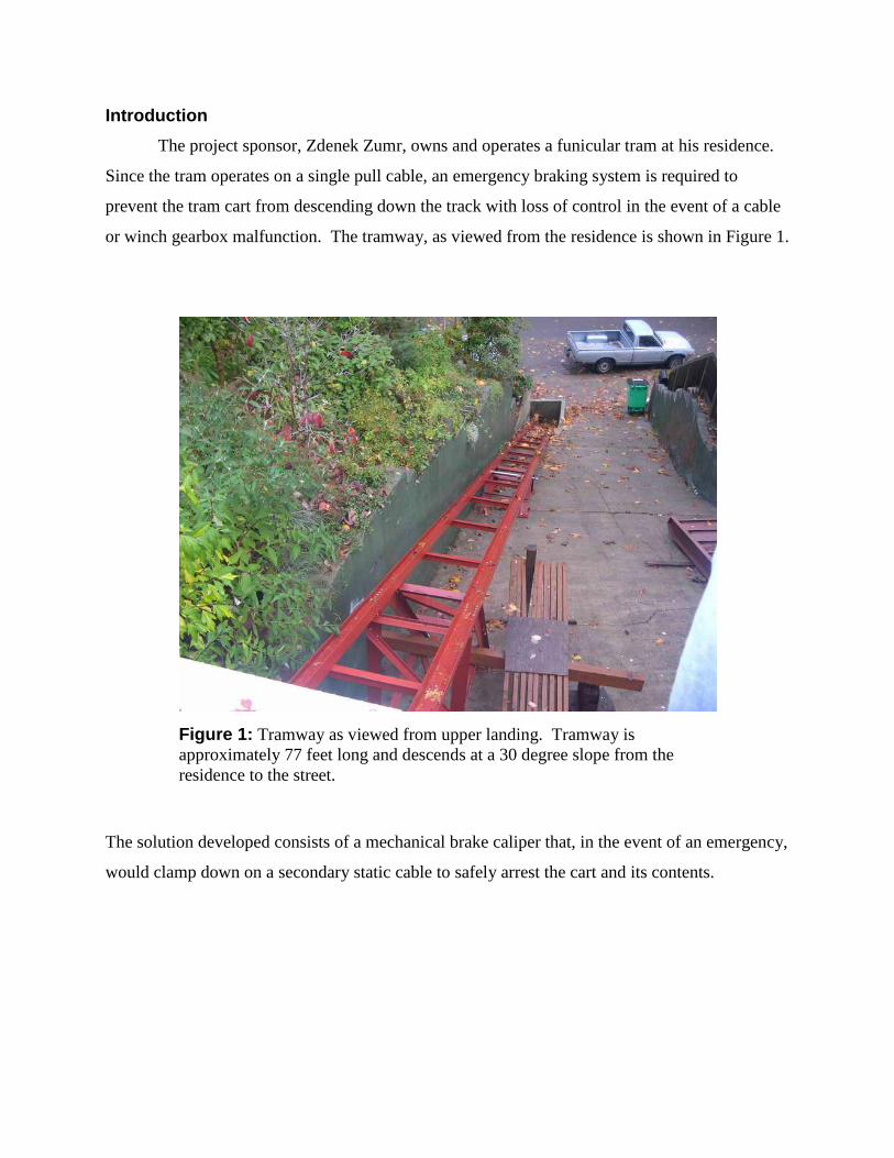
The project sponsor, Zdenek Zumr, owns and operates a funicular tram at his residence.
Since the tram operates on a single pull cable, an emergency braking system is required to
prevent the tram cart from descending down the track with loss of control in the event of a cable
or winch gearbox malfunction. The tramway, as viewed from the residence is shown in Figure 1.
The solution developed consists of a mechanical brake caliper that, in the event of an emergency,
would clamp down on a secondary static cable to safely arrest the cart and its contents.
Figure 1: Tramway as viewed from upper landing. Tramway is
approximately 77 feet long and descends at a 30 degree slope from the
residence to the street.

Mission Statement
An emergency braking system for a funicular tram located at the project sponsors
residence is to be designed and prototyped. The braking system is to operate automatically in the
event of a pull cable or winch gearbox malfunction. The braking system should either stop the
tram cart, or allow the cart to descend to the bottom of the tramway at a controlled velocity of no
more than 2 ft/sec. If the braking system is to stop the tram cart, a provision for manual
operation of the brake may be included to allow an occupant on the cart to descend to the bottom
of the tramway. The braking system must be reliable, mechanical (non-electrical), and operate
without the destruction of major braking system components. Documentation of the mechanism,
including Bill of Materials (BOM), operating and maintenance instructions (O&M), and
Assembly Drawings are to be delivered with the prototype.
Main Design Requirements
The design team determined that the following requirements were highly important to the
success of the project:
Brake system will automatically stop the cart (total combined weight < 800 lbs) in
an emergency
The system should have a manual brake release on the cart
Stopping acceleration will not be greater than the acceleration experienced at
startup
All components must be mechanical
The braking system should capture the cart to the track while still allowing for the
cart to be removed easily when necessary
The minimum factor of safety for all brake system components must be at least 2
An exhaustive list of design requirements is listed in the PDS provided in Appendix G.
Top Level Design Alternatives
Internal search, External search, and brainstorming provided seven top level design
concepts to the design team for concept evaluation. The top level concepts fell into three basic
categories: direct friction applied to a structural member, direct friction applied to a secondary
cable, and brakes controlling the rotation of a shaft whose rotation was caused by movement of
the cart.
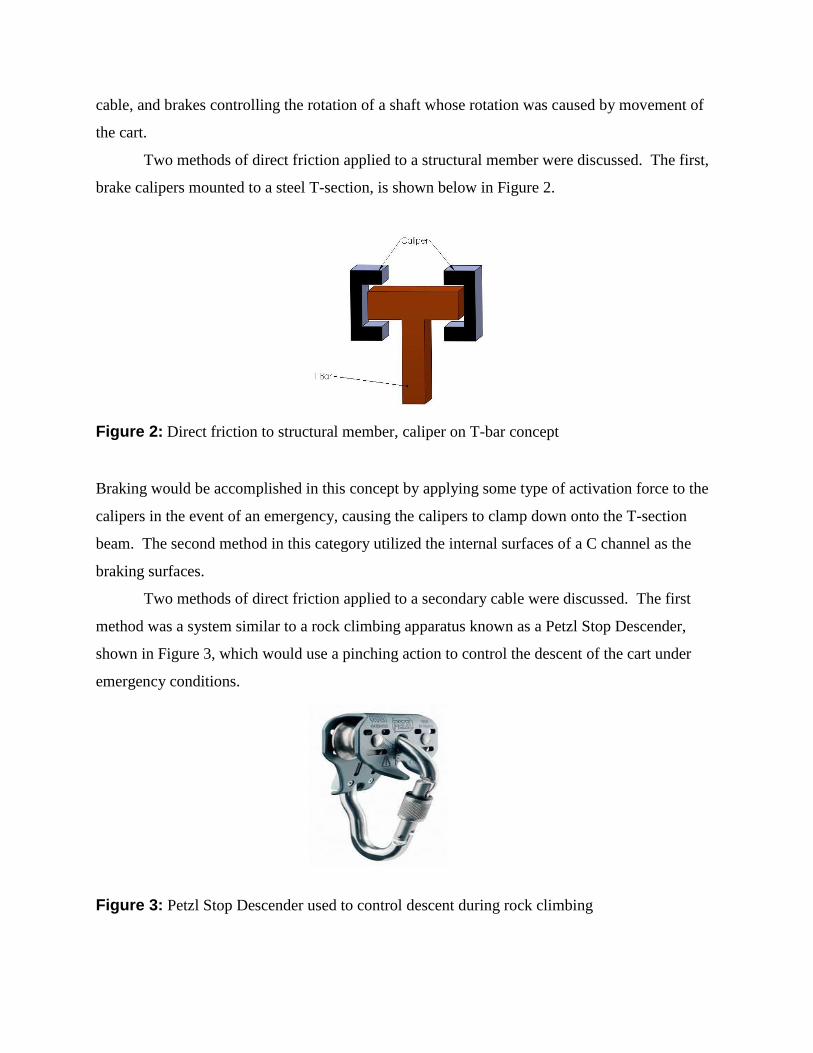
Two methods of direct friction applied to a structural member were discussed. The first,
brake calipers mounted to a steel T-section, is shown below in Figure 2.
Figure 2: Direct friction to structural member, caliper on T-bar concept
Braking would be accomplished in this concept by applying some type of activation force to the
calipers in the event of an emergency, causing the calipers to clamp down onto the T-section
beam. The second method in this category utilized the internal surfaces of a C channel as the
braking surfaces.
Two methods of direct friction applied to a secondary cable were discussed. The first
method was a system similar to a rock climbing apparatus known as a Petzl Stop Descender,
shown in Figure 3, which would use a pinching action to control the descent of the cart under
emergency conditions.
Figure 3: Petzl Stop Descender used to control descent during rock climbing

The second concept in this category was the caliper on cable method. A brake caliper mounted
directly on a cable, as shown in Figure 4, would be used to control the descent of the cart.
Three methods of brakes controlling the rotation of a secondary shaft were discussed.
These three options were all relatively complicated, and expensive to install initially. All three
options were ruled out during the decision making step of the process, and due to their
complexity none of the options is pictured here.
Construction of a decision matrix based on PDS requirements lead to the choice of the
brake caliper mounted directly to a secondary cable as the top level design for this project.
Reliability was given the most weight in the decision making process, and the concept chosen
should be highly reliable due to the simplicity of the concept. Other important PDS constraints
met by the caliper on cable concept are listed below
the system is completely mechanical
the system operates in a non-destructive manner to major system components
installation and maintenance costs are low
the tram cart is captured to the track by a secondary cable
This concept also allowed for a relatively simple manual override system to be designed and
installed.
Final Product Design
The final design of the product utilizes a secondary cable stretched from the top to the
bottom of the tramway. The secondary cable passes through a mechanical brake caliper which is
Figure 4: Cable On Caliper concept sketch

attached to the tram cart. A linkage set connects the winch pull cable to the caliper, and a spring
is utilized to apply braking force to the caliper in the event of an emergency. Figures 4, 5 & 6
provide models of the complete braking system. The braking system features three distinct sub-
units: the caliper assembly, the caliper activation assembly, and the cable guides.
Figure 4: Model of the complete caliper on cable design. (side view)
Figure 5: Model of the complete caliper on cable design. (opposite side view)
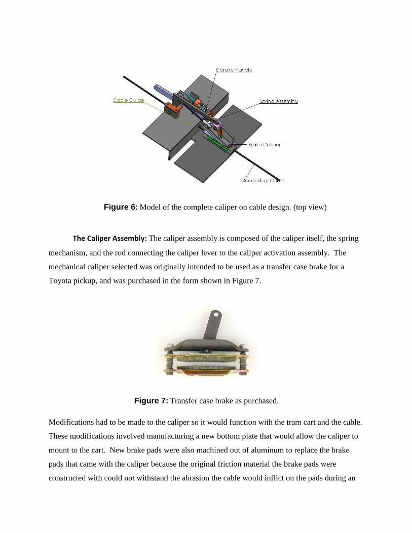
The Caliper Assembly: The caliper assembly is composed of the caliper itself, the spring
mechanism, and the rod connecting the caliper lever to the caliper activation assembly. The
mechanical caliper selected was originally intended to be used as a transfer case brake for a
Toyota pickup, and was purchased in the form shown in Figure 7.
Modifications had to be made to the caliper so it would function with the tram cart and the cable.
These modifications involved manufacturing a new bottom plate that would allow the caliper to
mount to the cart. New brake pads were also machined out of aluminum to replace the brake
pads that came with the caliper because the original friction material the brake pads were
constructed with could not withstand the abrasion the cable would inflict on the pads during an
Figure 7: Transfer case brake as purchased.
Figure 6: Model of the complete caliper on cable design. (top view)
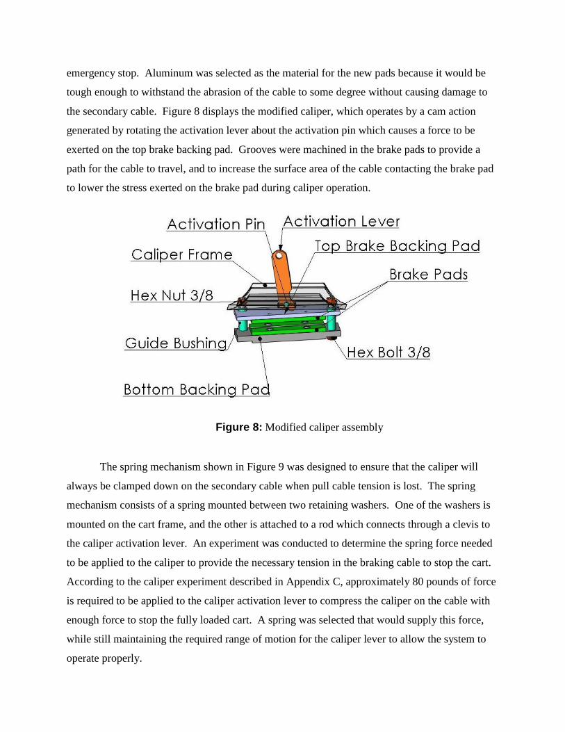
emergency stop. Aluminum was selected as the material for the new pads because it would be
tough enough to withstand the abrasion of the cable to some degree without causing damage to
the secondary cable. Figure 8 displays the modified caliper, which operates by a cam action
generated by rotating the activation lever about the activation pin which causes a force to be
exerted on the top brake backing pad. Grooves were machined in the brake pads to provide a
path for the cable to travel, and to increase the surface area of the cable contacting the brake pad
to lower the stress exerted on the brake pad during caliper operation.
Figure 8: Modified caliper assembly
The spring mechanism shown in Figure 9 was designed to ensure that the caliper will
always be clamped down on the secondary cable when pull cable tension is lost. The spring
mechanism consists of a spring mounted between two retaining washers. One of the washers is
mounted on the cart frame, and the other is attached to a rod which connects through a clevis to
the caliper activation lever. An experiment was conducted to determine the spring force needed
to be applied to the caliper to provide the necessary tension in the braking cable to stop the cart.
According to the caliper experiment described in Appendix C, approximately 80 pounds of force
is required to be applied to the caliper activation lever to compress the caliper on the cable with
enough force to stop the fully loaded cart. A spring was selected that would supply this force,
while still maintaining the required range of motion for the caliper lever to allow the system to
operate properly.
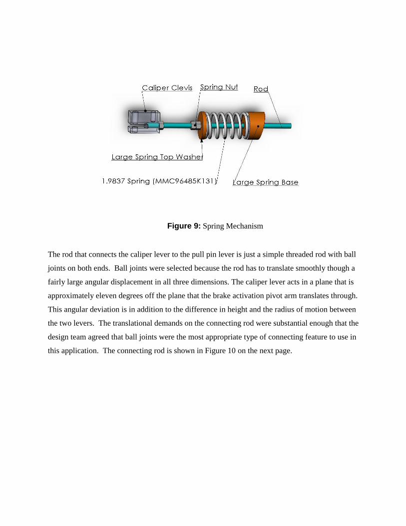
Figure 9: Spring Mechanism
The rod that connects the caliper lever to the pull pin lever is just a simple threaded rod with ball
joints on both ends. Ball joints were selected because the rod has to translate smoothly though a
fairly large angular displacement in all three dimensions. The caliper lever acts in a plane that is
approximately eleven degrees off the plane that the brake activation pivot arm translates through.
This angular deviation is in addition to the difference in height and the radius of motion between
the two levers. The translational demands on the connecting rod were substantial enough that the
design team agreed that ball joints were the most appropriate type of connecting feature to use in
this application. The connecting rod is shown in Figure 10 on the next page.

Figure 10: Connecting Rod Assembly
The Caliper Activation Assembly:
The caliper activation assembly connects the pull cable to the cart, deactivates the caliper
when the pull cable is tensioned, and allows for the brake to be manually released when pull
cable tension is lost. The assembly shown in Figure 11 is composed of four primary
components: the brake lever pin, the bearing blocks, the E-brake handle (manual release handle),
and the brake activation pivot arm.
Figure 11: Caliper Activation Assembly
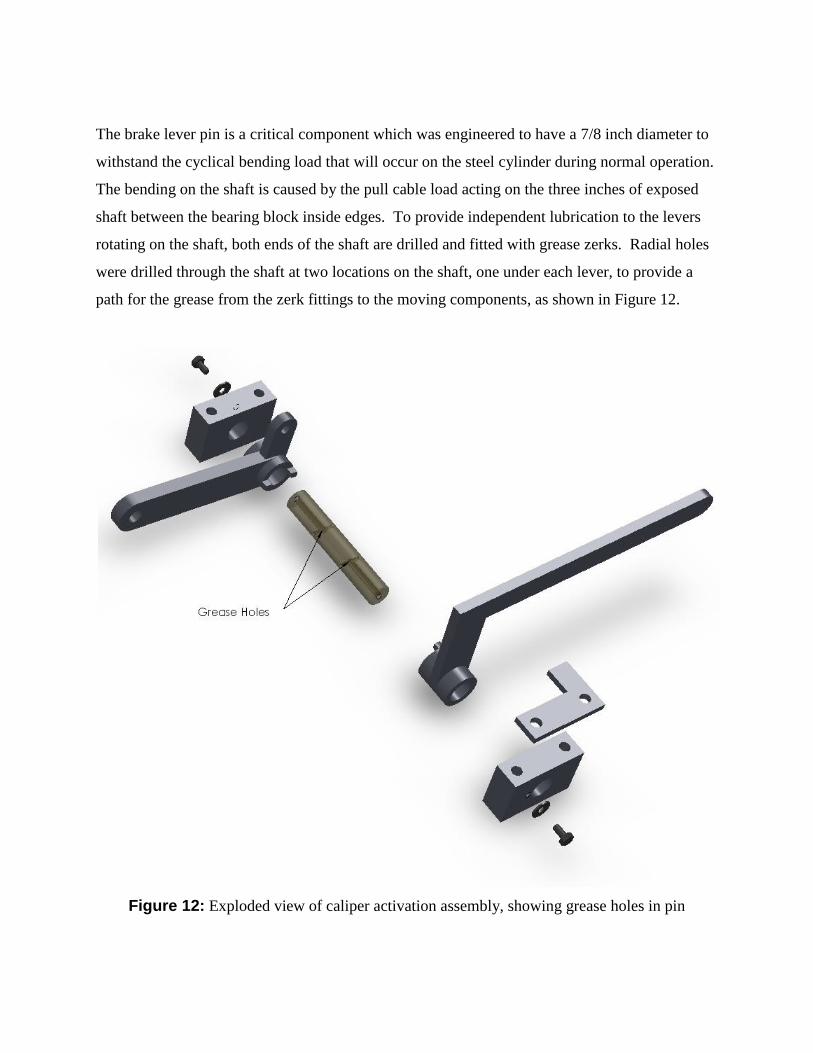
The brake lever pin is a critical component which was engineered to have a 7/8 inch diameter to
withstand the cyclical bending load that will occur on the steel cylinder during normal operation.
The bending on the shaft is caused by the pull cable load acting on the three inches of exposed
shaft between the bearing block inside edges. To provide independent lubrication to the levers
rotating on the shaft, both ends of the shaft are drilled and fitted with grease zerks. Radial holes
were drilled through the shaft at two locations on the shaft, one under each lever, to provide a
path for the grease from the zerk fittings to the moving components, as shown in Figure 12.
Figure 12: Exploded view of caliper activation assembly, showing grease holes in pin
The bearing blocks are each one piece, and machined from steel bar stock. Each bearing
block attaches to the cart frame with two 3/8 inch bolts which mount through vertical holes
drilled through the blocks. The bearing blocks also feature a drilled and tapped hole located just
outside the shaft hole. These holes receive ¼” bolts and flat washers that capture the shaft
between the two blocks when assembled, and function as inexpensive shaft retainers.
The block located on the same side of the assembly as the manual release handle is
equipped with an L-shaped section of stainless steel plate. The short leg of this L extends out
towards the release handle. This piece of material establishes a lower limit for the travel of the
release handle.
The manual release handle allows a passenger on the cart, after a pull cable or winch
malfunction, to release the brake caliper and return the cart to the bottom of the track in a
controlled manner. It is made out of two sections of flat steel bar stock that were welded into an
L-shape. This section was then welded onto a piece of steel bar stock that was machined to slide
over the brake lever pin (shaft). The unit was designed such that the hole though the tube was
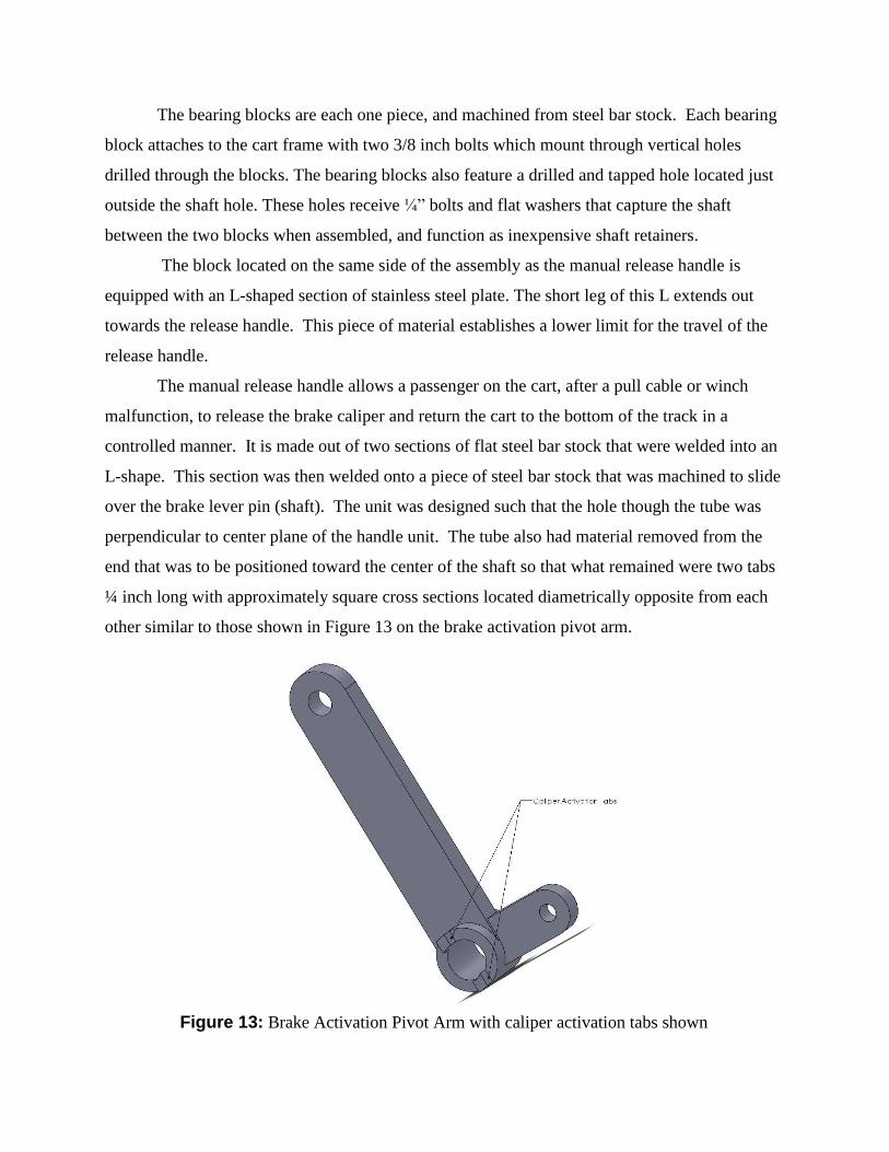
perpendicular to center plane of the handle unit. The tube also had material removed from the
end that was to be positioned toward the center of the shaft so that what remained were two tabs
¼ inch long with approximately square cross sections located diametrically opposite from each
other similar to those shown in Figure 13 on the brake activation pivot arm.
Figure 13: Brake Activation Pivot Arm with caliper activation tabs shown

These tabs mate with two identical tabs on the brake activation pivot arm when the caliper is
engaged and the release handle is pulled to open the caliper. The manner in which the tabs
engage allows the brake activation pivot arm to move independently of the E-brake handle, but
also gives the E-brake handle the capability of moving the brake activation pivot arm in
emergency conditions.
The brake activation pivot arm, shown in Figure 13, is the most important component of
the caliper activation assembly. This component engages and disengages the caliper based on
whether there is tension in the pull cable or not. The lever has two arms, one connects to the pull
cable and the other connects to the caliper through the rod and ball joints. The brake activation
pivot arm uses pull cable tension to overcome the pressure exerted on the caliper by the spring.
Preliminary calculations indicated that an empty cart moving downhill would not provide
adequate tension in the pull cable to overcome the spring force exerted on the brake activation
pivot arm with a 1:1 arm length ratio. Due to the critical nature of this factor on the performance
of the system the tension in the pull cable was measured. The minimum steady state force in the
cable was found to be 40 lbs. The ratio of mechanical advantage needed was determined to be
3:1 to overcome the spring pressure when compressed to normal operating conditions.
Therefore, the pull cable arm is three times longer than the caliper arm because this difference in
length creates the 3:1 mechanical advantage required to ensure the pull cable will always have
enough tension to keep the caliper open during normal operating conditions. The brake
activation pivot arm was machined out of steel. The two arms are welded onto a section of tube
that, like the manual release handle, fits over the shaft. As shown in Figure 13, this tube has two
square tabs milled out of the end facing the middle of the pull pin assembly that mate with the
tabs milled into the release handle to allow independent and dependent operation of the two
levers as needed.
Cable Guides
Two cable guides were installed on the cart. The purpose of the cable guides is to guide
the cable through the cart without exposing the cable to the sharp edges of the holes the cable
passes through, and to keep the secondary cable lined up with the groove machined into the
brake pads. A picture of the upper cable guide as installed on the cart is shown in Figure 14.
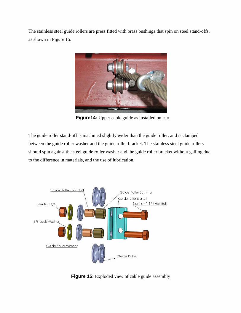
The stainless steel guide rollers are press fitted with brass bushings that spin on steel stand-offs,
as shown in Figure 15.
The guide roller stand-off is machined slightly wider than the guide roller, and is clamped
between the guide roller washer and the guide roller bracket. The stainless steel guide rollers
should spin against the steel guide roller washer and the guide roller bracket without galling due
to the difference in materials, and the use of lubrication.
Figure 15: Exploded view of cable guide assembly
Figure14: Upper cable guide as installed on cart
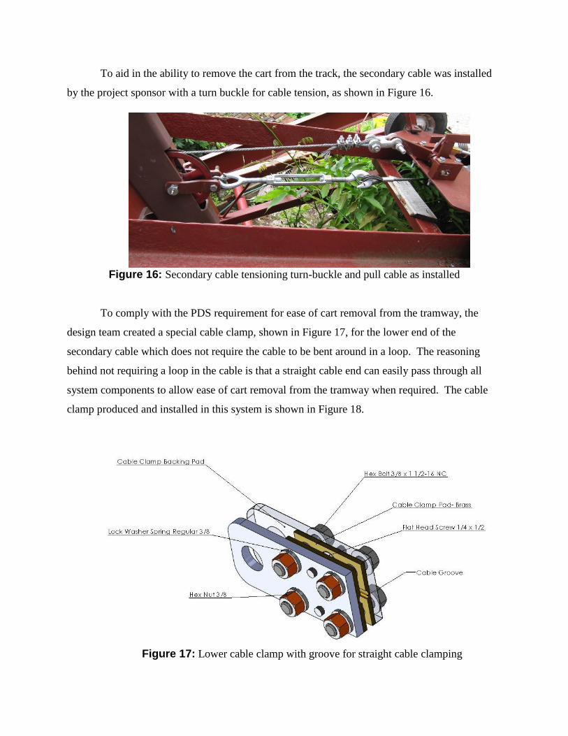
To aid in the ability to remove the cart from the track, the secondary cable was installed
by the project sponsor with a turn buckle for cable tension, as shown in Figure 16.
Figure 16: Secondary cable tensioning turn-buckle and pull cable as installed
To comply with the PDS requirement for ease of cart removal from the tramway, the
design team created a special cable clamp, shown in Figure 17, for the lower end of the
secondary cable which does not require the cable to be bent around in a loop. The reasoning
behind not requiring a loop in the cable is that a straight cable end can easily pass through all
system components to allow ease of cart removal from the tramway when required. The cable
clamp produced and installed in this system is shown in Figure 18.
Figure 17: Lower cable clamp with groove for straight cable clamping

The straight cable is inserted into the cable groove shown in Figure 15, and when the four 3/8
bolts are tightened, the secondary cable is securely held in place.
Final Product Evaluation
Final product evaluation was performed by testing and analyzing the prototype. The
product design specifications (PDS) for this system provided several required attributes that the
final product would be required to have. The most important of these were listed in the Main
Design Requirements section of this report. The design, as tested, functioned as it was designed
to. This claim is substantiated by several means, namely practical tests and experiments,
engineering analyses, and by physical inspection.
Three of the major PDS requirements listed earlier can be demonstrated to have been met
by visual inspection of the design of the system. The requirements that can be visually inspected
for conformance are:
The system will have a manual release on the cart
All components must be mechanical
The system must attach the cart to the track while still allowing the cart to be
removed when necessary
Figure 18: Lower cable clamp and anchor as installed
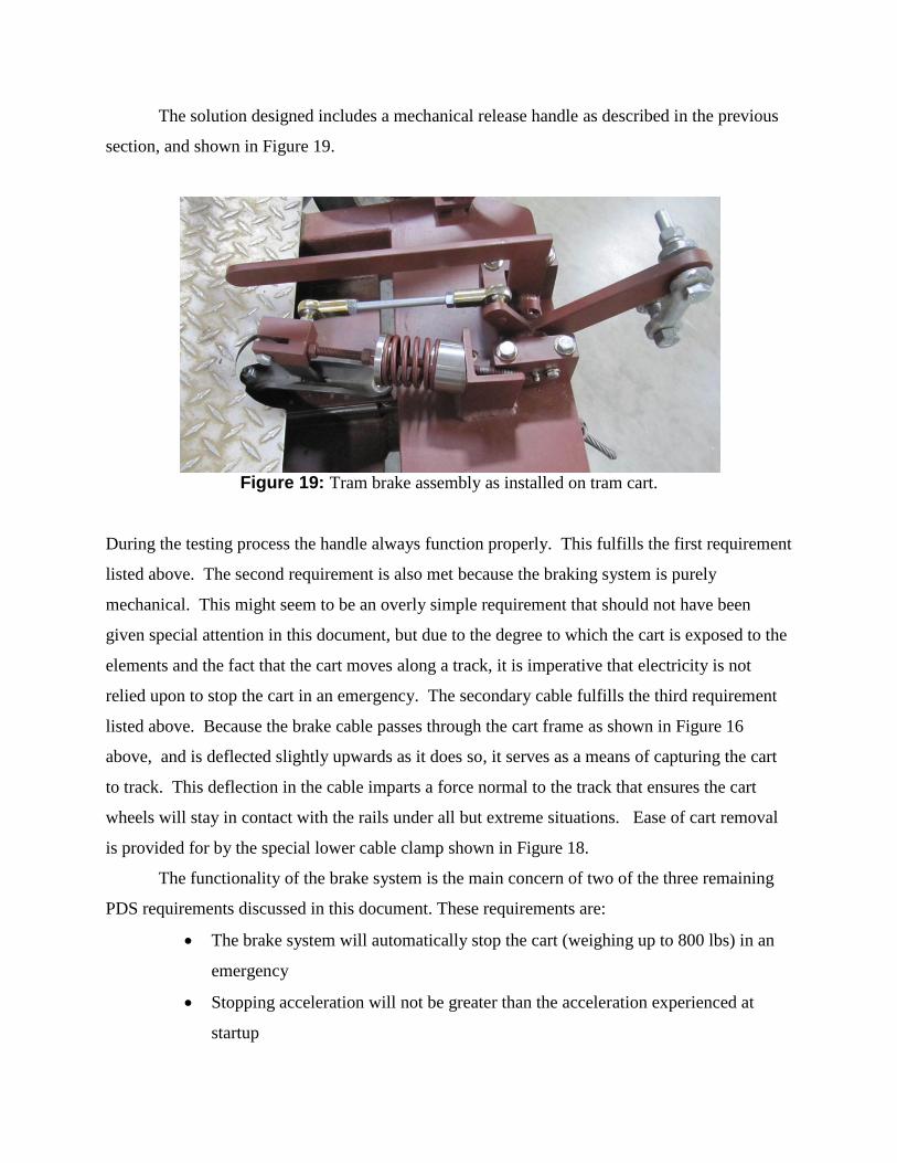
The solution designed includes a mechanical release handle as described in the previous
section, and shown in Figure 19.
Figure 19: Tram brake assembly as installed on tram cart.
During the testing process the handle always function properly. This fulfills the first requirement
listed above. The second requirement is also met because the braking system is purely
mechanical. This might seem to be an overly simple requirement that should not have been
given special attention in this document, but due to the degree to which the cart is exposed to the
elements and the fact that the cart moves along a track, it is imperative that electricity is not
relied upon to stop the cart in an emergency. The secondary cable fulfills the third requirement
listed above. Because the brake cable passes through the cart frame as shown in Figure 16
above, and is deflected slightly upwards as it does so, it serves as a means of capturing the cart
to track. This deflection in the cable imparts a force normal to the track that ensures the cart
wheels will stay in contact with the rails under all but extreme situations. Ease of cart removal
is provided for by the special lower cable clamp shown in Figure 18.
The functionality of the brake system is the main concern of two of the three remaining
PDS requirements discussed in this document. These requirements are:
The brake system will automatically stop the cart (weighing up to 800 lbs) in an
emergency
Stopping acceleration will not be greater than the acceleration experienced at
startup

Both of these requirements have been met. This was demonstrated by the testing done with the
completed system on the track at the project sponsor’s residence. With the brake system fully set
up and configured for use, multiple tests were conducted with different loads on the cart ranging
from zero additional weight to a weight approximately equal to the maximum cargo capacity
specified in the PDS document (600 lbs.). The initial tests consisted of simply running the tram
up and down the track under with various loads to ensure that the brake system would not
impede normal operation. It did not, and there was not a noticeable difference in the way the cart
traveled along the track when compared to the way things were before the brake system was
added. The next round of testing comprised of trials that examined the effectiveness of the brake
in a situation where the pull cable failed. This event was simulated by removing the pull cable
from the shackle attaching it to the pull cable lever arm and replacing it with a length of string.
The cart was then loaded and the string was cut. Every trial conducted proved to be successful.
At most the cart glided one or two inches down the track before being brought to a stop. A
dynamic test was also conducted, where the cart was set up as described previously with the
string connecting the cart to the pull cable and then the pull cable winch was allowed to free
spool for a few seconds before being stopped. Once the winch was locked, the string snapped
and the brake system brought the cart to a smooth and quick stop. Travel down the track after
the point of caliper engagement was minimal. This test was conducted with the maximum
amount of weight loaded onto the cart and the result was a success. The project sponsor found
the stopping acceleration to be acceptable during all testing performed. This testing process
demonstrates that the design team has successfully met the functional requirements discussed
earlier.
The final major requirement in the PDS document was that the entire system be designed
with a minimum safety factor of 2. This was taken into account in the engineering analyses that
were performed during the detailed design portion of this project. These analyses can be found
in the Appendices C. Due to the available standard sizes of material stock and the fact that most
of the material used to machine components for this system was donated, most of the safety
factors for the components as they were built for this project are greater than 2. The actual safety
factors for the components are listed in Table 1 on the next page.

Table 1: Actual safety factors of components as built
Component Minimum Factor of Safety
Activation Lever 10.82
Pull Cable Bolt 5.03
Pillow Block Bolts 5.65
Activation Shaft 2.33
Brake Cable 4.18
Connecting Rod 17.67
Activation Tabs 108.00
Additional requirements of the PDS that were met by visual inspection are: all hardware
to be zinc or Cd plated, exposed steel surfaces were painted, where possible off-the-shelf parts
were used, the system was designed to minimize components wear, all lubrication point are
easily accessible, and the e-brake handle is conveniently placed to allow easy operation.
This project fell within the allotted $1,000.00 budget with the overall project cost as
shown in Appendix I totaling $ 293.58. The major reason for cost containment on this project
was that much of the material was donated, as was the tooling used to make the components.
Appendix I provides a complete list of expenditures for this project.
In conclusion, the braking system that was designed and prototyped fully meets the
requirements as specified by both the project sponsor Zdenek Zumr, and the elements recorded
in the PDS document. The final product is an emergency brake system that will arrest Mr.
Zumr’s funicular tram in the event of a pull cable or winch failure. The system was designed
and prototyped on schedule and under budget. Testing has proven that the design works as it
was designed to. This project was a success based on acceptable performance of the system, and
the fact that the PDS requirements were met. In addition, our sponsor has reviewed the final
product and approved the entire system based on his own inspection of the prototype, and
witnessing the operational testing of said prototype. A statement of approval from our project
sponsor is provided in Appendix J.

A-1
Appendix A: Detailed Description of Design, Manufacturing, and Assembly
The braking system design is comprised of four distinct sub-units: the caliper assembly,
the caliper activation assembly, the spring force assembly, and the secondary cable routing
components. This appendix describes the individual systems initially, and then the combination
of the systems into the final assembly.
Caliper Assembly
A completely mechanical brake caliper was selected for this project due to the reliability
needed of a system which may remain stationary for many years, but yet be called upon to work
without fail in the event of an emergency. The mechanical caliper selected was originally
intended to be used as a transfer case brake for a Toyota pickup, and was purchased in the form
shown in Figure A-1.
The caliper functions by rotation of the activation lever about the activation pin. The activation
pin rests in a pocket formed into the upper frame. The end of the activation lever has a cam
profile that contacts the upper brake backing pad. The upper brake backing pad slides on the
bushings when the activation lever is rotated which causes a compressive force to be exerted on
the cable between the brake pads. The components described above are annotated in the
exploded view shown on page A-2.
Figure A-1: Transfer case brake caliper as purchased.
A-2
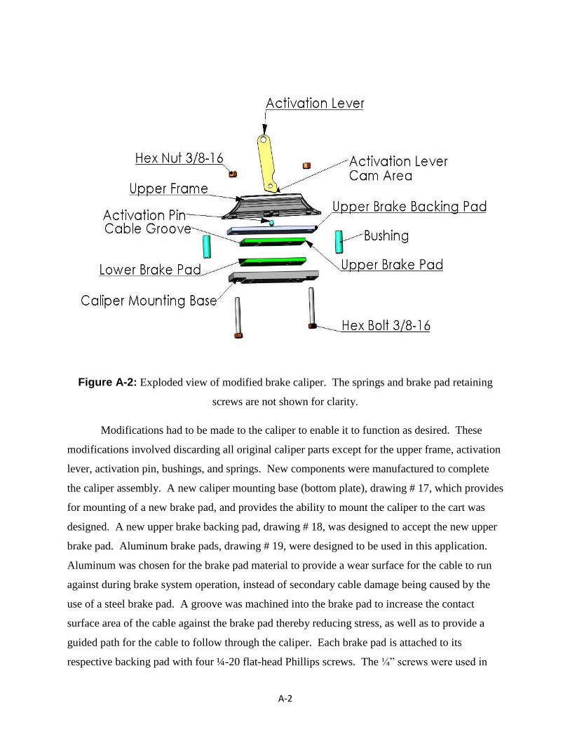
Figure A-2: Exploded view of modified brake caliper. The springs and brake pad retaining
screws are not shown for clarity.
Modifications had to be made to the caliper to enable it to function as desired. These
modifications involved discarding all original caliper parts except for the upper frame, activation
lever, activation pin, bushings, and springs. New components were manufactured to complete
the caliper assembly. A new caliper mounting base (bottom plate), drawing # 17, which provides
for mounting of a new brake pad, and provides the ability to mount the caliper to the cart was
designed. A new upper brake backing pad, drawing # 18, was designed to accept the new upper
brake pad. Aluminum brake pads, drawing # 19, were designed to be used in this application.
Aluminum was chosen for the brake pad material to provide a wear surface for the cable to run
against during brake system operation, instead of secondary cable damage being caused by the
use of a steel brake pad. A groove was machined into the brake pad to increase the contact
surface area of the cable against the brake pad thereby reducing stress, as well as to provide a
guided path for the cable to follow through the caliper. Each brake pad is attached to its
respective backing pad with four ¼-20 flat-head Phillips screws. The ¼” screws were used in
A-3
this application because all hardware was donated, and the ¼” flathead screw was the smallest
screw available in the donated supplies. These screws act in shear in this application, and the
shear strength of a single ¼” bolt is much greater than the load that could be applied by this
system. Since four bolts are used per brake pad, no analysis was performed on these screws, and
they were tightened to a torque value of 66 in-lbs per Appendix H.
The modified caliper was used to test the concept as described in Appendix C. No initial
estimate of the force generated in the cable as it was being pulled through the closed caliper was
available initially, and the prototype pads for testing were not originally going to be the brake
pads used in the final assembly, so the bolt size to mount the caliper to the test fixture were
intentionally oversized to eliminate the possibility of failure during testing. Due to time
constraints, the initial test prototype lower backing pad for the caliper was used in the final
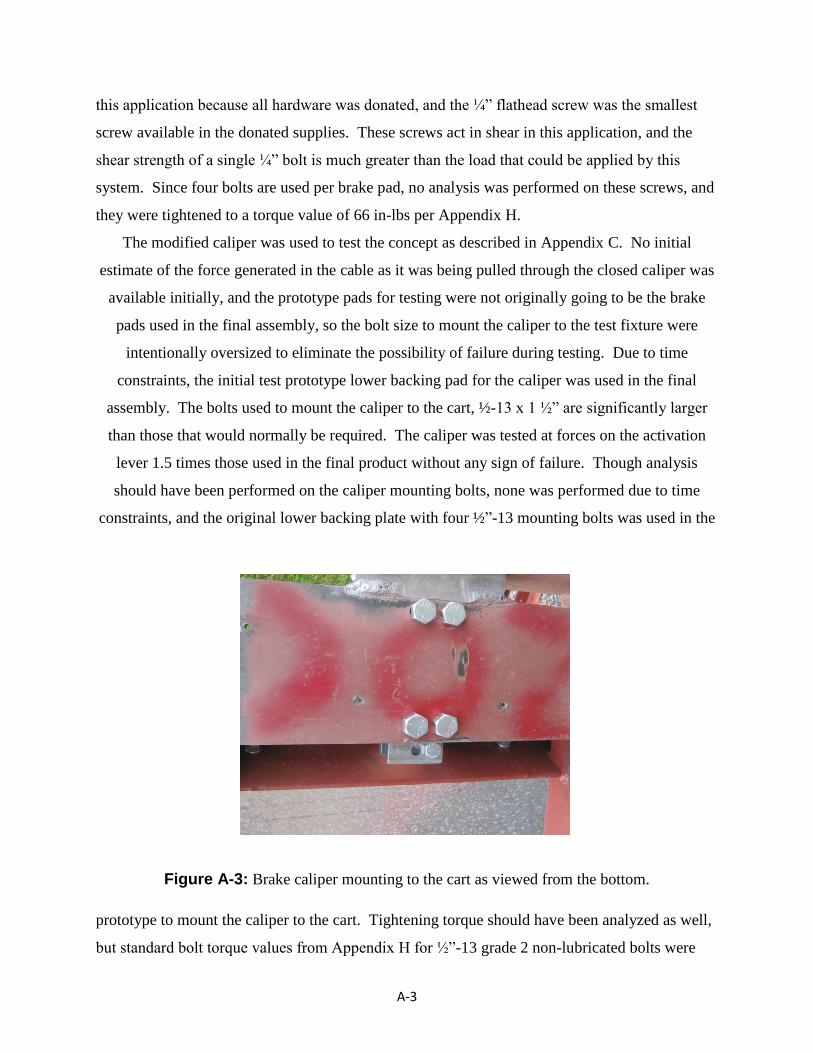
assembly. The bolts used to mount the caliper to the cart, ½-13 x 1 ½” are significantly larger
than those that would normally be required. The caliper was tested at forces on the activation
lever 1.5 times those used in the final product without any sign of failure. Though analysis
should have been performed on the caliper mounting bolts, none was performed due to time
constraints, and the original lower backing plate with four ½”-13 mounting bolts was used in the
Figure A-3: Brake caliper mounting to the cart as viewed from the bottom.
prototype to mount the caliper to the cart. Tightening torque should have been analyzed as well,
but standard bolt torque values from Appendix H for ½”-13 grade 2 non-lubricated bolts were

A-4
used, and the caliper mounting bolts were tightened to a torque value of 50 ft-lbs. The grade 2
specification was used because the lower backing plate was constructed from mild steel bar
stock. The caliper mounting holes in the cart frame were slotted slightly to allow the caliper
cable groove to be lined up with the secondary cable during final assembly to prevent brake pad
wear due to caliper misalignment. Figure A-3 shows the caliper as mounted to the cart from the
bottom side.
The 3/8-16 x 3” bolts that hold the caliper together were also tested in the experiment
performed, which was previously mentioned. These bolts were tightened to 30 ft-lbs per
Appendix H. No analysis was done on these bolts for the same reasons given for the caliper
mounting bolts.
Caliper Activation Assembly
The caliper activation assembly connects the pull cable to the cart, deactivates the caliper
when the pull cable is tensioned, and allows for the brake to be manually released when pull
cable tension is lost. The assembly shown in Figure A-4 is composed of four primary
components: the brake lever pin, the bearing blocks, the E-brake handle (manual release handle),
and the brake activation pivot arm.
Figure A-4: Caliper Activation Assembly
A-5
The brake lever pin is a critical component which was engineered to have a 7/8 inch
diameter to withstand the cyclical bending load that will occur on the steel cylinder during
normal operation. The minimum tension in the pull cable during dynamic conditions was
measured to be 40 lbs. This measurement was performed using a 200lb spring scale connected
between the cart and the pull cable. It was noted during testing that the transient start-up load
was approximately 3.5 times the steady state dynamic load. The bending on the shaft is caused
by the pull cable load acting on the three inches of exposed shaft between the bearing block
inside edges. The brake lever pin was sized to withstand the cyclical loading in the transient
state.
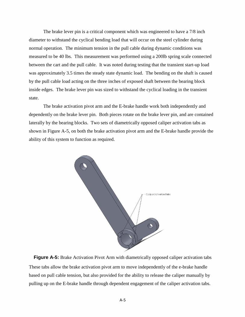
The brake activation pivot arm and the E-brake handle work both independently and
dependently on the brake lever pin. Both pieces rotate on the brake lever pin, and are contained
laterally by the bearing blocks. Two sets of diametrically opposed caliper activation tabs as
shown in Figure A-5, on both the brake activation pivot arm and the E-brake handle provide the
ability of this system to function as required.
Figure A-5: Brake Activation Pivot Arm with diametrically opposed caliper activation tabs
These tabs allow the brake activation pivot arm to move independently of the e-brake handle
based on pull cable tension, but also provided for the ability to release the caliper manually by
pulling up on the E-brake handle through dependent engagement of the caliper activation tabs.
A-6
The brake activation pivot arm engages and disengages the caliper based on whether
there is tension in the pull cable or not. The lever has two arms, one connects to the pull cable
and the other connects to the caliper through the rod and ball joints (yet to be discussed). The
brake activation pivot arm uses pull cable tension to overcome the pressure exerted on the caliper
by the spring (yet to be discussed). Calculations indicated that an empty cart moving downhill
would not provide adequate tension in the pull cable to overcome the spring force exerted on the
brake activation pivot arm with a 1:1 arm length ratio. Due to the critical nature of this factor on
the performance of the system the tension in the pull cable was measured. The minimum steady
state force in the cable was found to be 40 lbs. The ratio of mechanical advantage needed was
determined to be 3:1 to overcome the spring pressure when compressed to normal operating
conditions. Therfore, the pull cable arm is three times longer than the caliper arm because this
difference in length creates the 3:1 mechanical advantage required to ensure the pull cable will
always have enough tension to keep the caliper open during normal operating conditions.
The E-brake handle was incorporated in this design to provide a manual means of
overriding the automatic braking system. This ability was deemed necessary in the event a
passenger was on the cart during an event that led to brake system activation. Through the use of
the E-brake handle, an occupant of the cart can descend to the lower landing of the tramway in a
controlled manner. The E-brake handle engages the caliper activation arm as previously
described to make the controlled descent possible. A brake lever stop was provided to act as a
rotation limiting device to maintain the rotational position of the E-brake handle in an
aesthetically pleasing position while not in use.
The bearing blocks provide containment of the brake lever pin, caliper activation arm,
and E-brake handle. These blocks also provide for mounting of the assembly to the cart frame.
The brake lever pin is contained between the blocks by bolts with flat washer that protrude past
the brake lever pin bores on the outside edges of the bearing blocks as shown in Figure A-4. The
brake lever stop mounts to the top of the bearing block on the same side as the E-brake handle.
The brake lever pin was machined from steel bar stock. The raw bar stock was
tightened in a three jaw chuck on an engine lathe. The tailstock end of the bar was center drilled,
and a live center was mounted in the tailstock to prevent deflection of the shaft during the
turning process. The shaft was turned to diameter in the lathe, the shaft was cut to length with a
parting tool, and both ends were then chamfered with a 45° tool per drawing #24. To provide
A-7
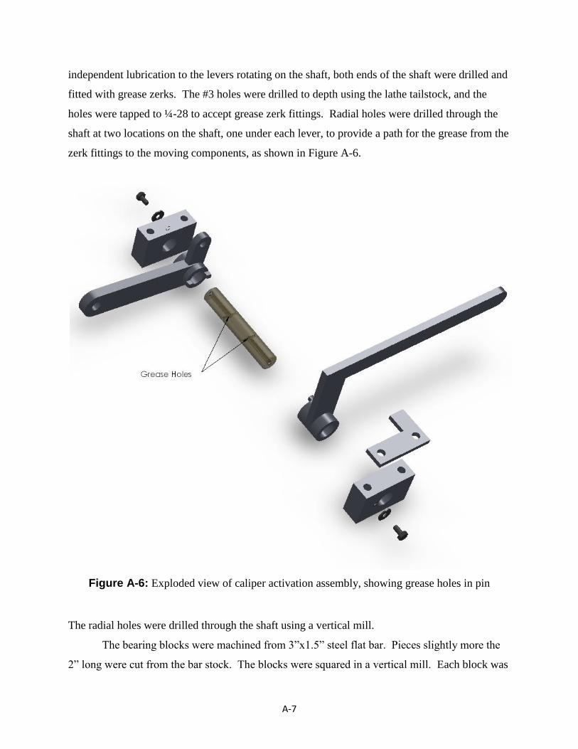
independent lubrication to the levers rotating on the shaft, both ends of the shaft were drilled and
fitted with grease zerks. The #3 holes were drilled to depth using the lathe tailstock, and the
holes were tapped to ¼-28 to accept grease zerk fittings. Radial holes were drilled through the
shaft at two locations on the shaft, one under each lever, to provide a path for the grease from the
zerk fittings to the moving components, as shown in Figure A-6.
Figure A-6: Exploded view of caliper activation assembly, showing grease holes in pin
The radial holes were drilled through the shaft using a vertical mill.
The bearing blocks were machined from 3”x1.5” steel flat bar. Pieces slightly more the
2” long were cut from the bar stock. The blocks were squared in a vertical mill. Each block was
A-8
placed in a vise on the mill. A 6” diameter, 10 insert face mill was installed in the mill spindle.
The blocks were placed on parallels to allow the surface which needed to be cut to extend past
the top of the vise. Since the flat bar was 1.5” thick, and the part only needed to be 1” thick,
approximately 0.450” of material was removed from the side of each block. The blocks were de-
burred, then rotated so that the previously cut side was against the stationary vise jaw. A round
pin was placed between the clamping vise jaw and the block, and the vise was tightened.
Material was removed from the block until cleanup of the surface was attained. The process of
rotating the block was continued until the width and height dimensions were attained, with the
clamping pin not being needed for the fourth surface. The blocks were then rotated, and squared
to the mill table to allow the length dimension to be cut squarely to the block. The brake lever
pin holes were center drilled, for hole location accuracy, drilled through, and reamed to size per
drawing # 20. The ¼-20 holes for pin retention were center drilled, tap drilled with a #7 drill, the
holes were chamfered for thread relief, and then tapped to ¼-20. The mounting holes were
center drilled, and drilled through with a 25/64 drill.
The brake activation pivot arm is composed of three pieces, the pull cable bar, the caliper
bar, and the center tube. The pull cable bar was made by cutting a piece of ½”x1.5” flat bar to
length. The bar was milled to 1 3/8” wide. An adjustable milling cutter known as a criterion
head was adjusted to cut a 1.375” diameter hole, and the end of the bar that mounts to the tube
was cut with a profile to match that of the OD of the tube. The hole for the pull cable was drilled
to 17/32” per drawing #12. The end of the bar was rounded using an 18” disc sander. The
caliper arm was cut to length from 5/16” x 1” flat bar. The criterion head previously mentioned
was used to generate the round profile on the tube end. The other end was rounded using the 18”
disc sander. The arm was fitted with 3/8-24 threads to connect to the caliper rod. The tubular
center section was made from 1 ¾” steel bar stock. The OD of the bar was turned to size, and
the center was drilled within 0.05” of finished diameter. The bore diameter was finished with a
small boring bar. The piece was cut to length using a parting tool. The diametrically opposed
tabs were cut into the end of the part on a vertical mill with a ¾” endmill. The two arms were
ground to fit the contour of the tube appropriately, glass beaded to remove surface impurities and
metal scale, and were TIG welded to the tube by an expert welder.
The E-brake handle was manufactured in much the same manner as the brake activation
pivot arm per drawing #11.
A-9
The brake lever stop was sawed from a section of ¼” x 2” Stainless Steel flat bar. A 3”
length was cut using a horizontal band saw. The 25/64 diameter holes were drilled on the mill.
The L-section was cut out on a vertical band saw. The part was finished using a vertical belt
sander.
Spring Force Assembly
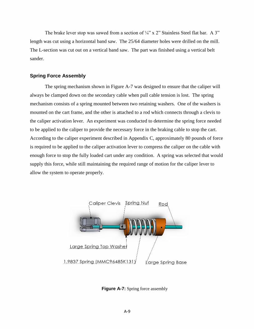
The spring mechanism shown in Figure A-7 was designed to ensure that the caliper will
always be clamped down on the secondary cable when pull cable tension is lost. The spring
mechanism consists of a spring mounted between two retaining washers. One of the washers is
mounted on the cart frame, and the other is attached to a rod which connects through a clevis to
the caliper activation lever. An experiment was conducted to determine the spring force needed
to be applied to the caliper to provide the necessary force in the braking cable to stop the cart.
According to the caliper experiment described in Appendix C, approximately 80 pounds of force
is required to be applied to the caliper activation lever to compress the caliper on the cable with
enough force to stop the fully loaded cart under any condition. A spring was selected that would
supply this force, while still maintaining the required range of motion for the caliper lever to
allow the system to operate properly.
Figure A-7: Spring force assembly
A-10
The caliper clevis connects the spring force assembly to the caliper, and also provides a
mounting location for the connecting rod that connects the caliper to the caliper activation
assembly.
The spring washers were machined from 2 1/16” Stainless Steel bar stock. The top
washer was turned to size in an engine lathe per drawing #14, and the center hole was drilled
using a 7/16” drill in the tailstock. The washer was cut to length with a parting tool. The spring
base OD, overall length, and center hole were cut in the same manner as the top washer, per
drawing #?. The angled base was cut by placing the spring base into the mill vise at the
appropriate angle, and facing the base to the appropriate overall length. The mounting holes
were drilled and counter-bored with the spring base resting on the face previously milled to
allow the hole to be perpendicular to the mounting surface.
The caliper clevis was cut from a piece of 2” square stock. The piece was cut to length in
a horizontal band saw. The perimeter was milled to drawing #10 specifications in a vertical mill.
The groove for attachment to the caliper was placed such that the caliper activation lever makes
contact with the shank of the 3/8 bolt connecting the caliper activation lever to the caliper clevis.
The bolt used, tightens into the clevis by running out of thread, thus leaving only the shank of the
bolt exposed to the caliper activation lever, and preventing the clevis from collapsing when the
bolt is tightened. The groove for the caliper activation lever was cut using a ¼” endmill, and the
groove was cut in a manner which provides additional relief to allow for the large degree of
angular travel that occurs between the caliper clevis and caliper activation arm. The mounting
point for the spring assembly is in plane with the caliper activation assembly, and was drilled and
tapped to 3/8-16 in the vertical mill. The hole for the caliper connecting rod was fitted with 3/8-
24 threads, and the hole was made in the vertical mill.
Assembly of the components was performed after the caliper was installed. A relief was
cut into the spring assembly side bearing block to allow for clearance of the threaded rod for the
spring assembly. The spring base was secured to the spring base mount location on the cart
using ¼-20 socket head cap screws torqued to 96 in-lbs per Appendix H standard torque
specifications for dry grade 5 bolts. An 8.75” section of 3/8-16 threaded rod was cut and the
spring, top washer, and (3) 3/8”-16 nuts were placed on the threaded rod. One end of the rod
was placed through the spring base, and the other end was threaded into the caliper clevis. One
A-11
3/8 nut was used to jam nut the threaded rod to the caliper clevis. The other two nuts were left
loose for final adjustment of the spring tension after cable installation.
Secondary Cable Routing
The braking system required the installation of a secondary cable. The chosen design
fulfills a PDS requirement of securing the cart to the tramway by passing the cable through (2)
structural members, one at each end, of the cart. The secondary cable, upper attachment point,
upper cable clamps, secondary cable tensioning device, and lower attachment point were
provided by the project sponsor. The design team was tasked with providing cable guides to
guide the secondary cable through the cart, and a special cable clamp for the lower attachment
point which did not require the cable to be bent into a loop.
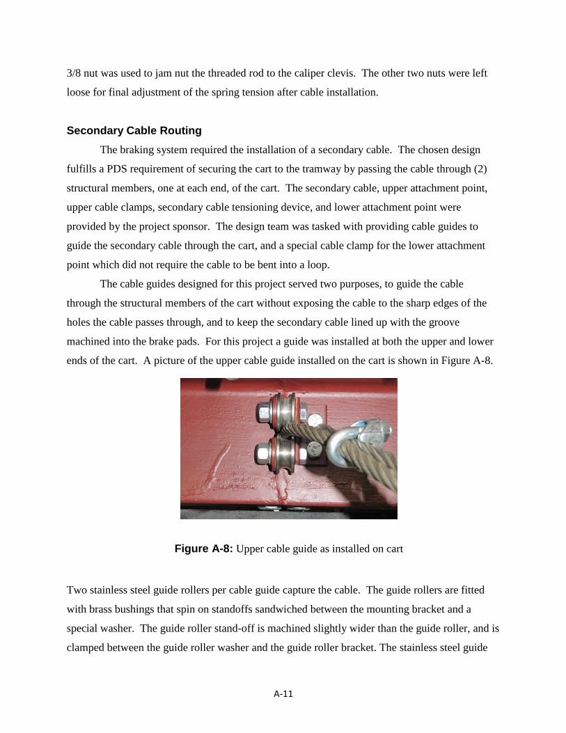
The cable guides designed for this project served two purposes, to guide the cable
through the structural members of the cart without exposing the cable to the sharp edges of the
holes the cable passes through, and to keep the secondary cable lined up with the groove
machined into the brake pads. For this project a guide was installed at both the upper and lower
ends of the cart. A picture of the upper cable guide installed on the cart is shown in Figure A-8.
Two stainless steel guide rollers per cable guide capture the cable. The guide rollers are fitted
with brass bushings that spin on standoffs sandwiched between the mounting bracket and a
special washer. The guide roller stand-off is machined slightly wider than the guide roller, and is
clamped between the guide roller washer and the guide roller bracket. The stainless steel guide
Figure A-8: Upper cable guide as installed on cart
A-12
rollers should spin against the steel guide roller washer and the guide roller bracket without
galling due to the difference in materials, and the use of lubrication.
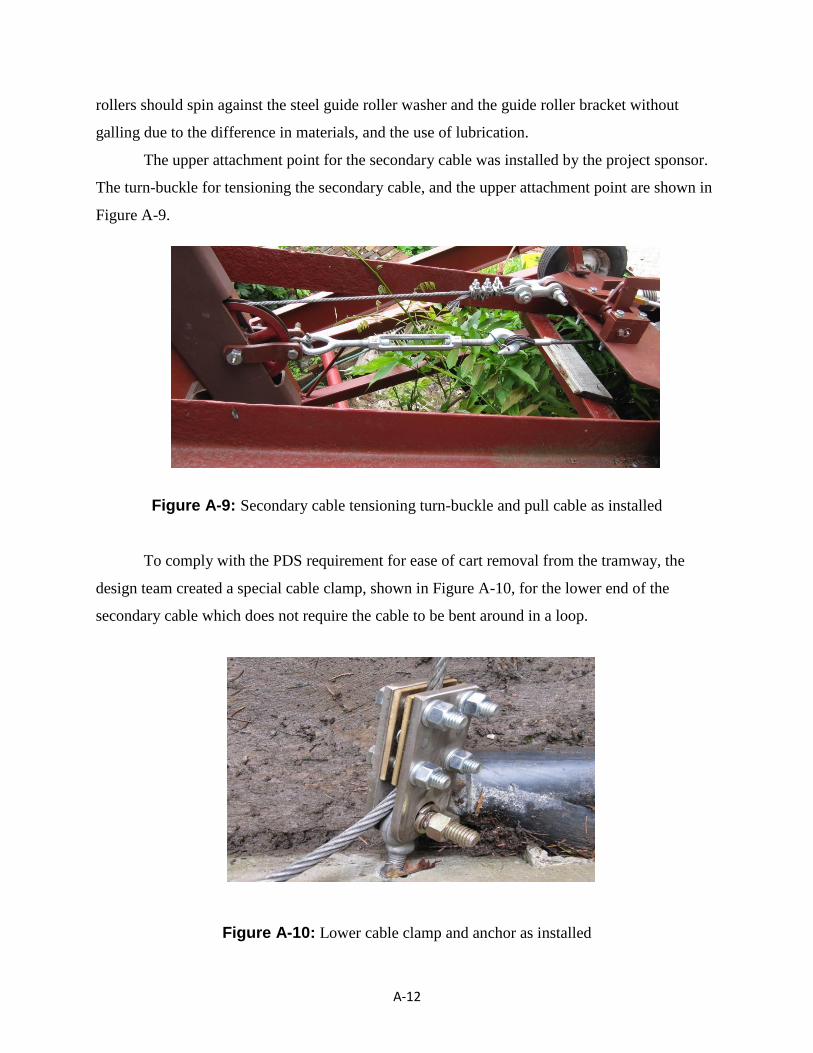
The upper attachment point for the secondary cable was installed by the project sponsor.
The turn-buckle for tensioning the secondary cable, and the upper attachment point are shown in
Figure A-9.
Figure A-9: Secondary cable tensioning turn-buckle and pull cable as installed
To comply with the PDS requirement for ease of cart removal from the tramway, the
design team created a special cable clamp, shown in Figure A-10, for the lower end of the
secondary cable which does not require the cable to be bent around in a loop.
Figure A-10: Lower cable clamp and anchor as installed
A-13
The rationale behind not requiring a loop in the cable is that a straight cable end can
easily pass through all system components to allow ease of cart removal from the tramway when
required.
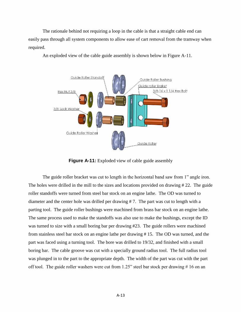
An exploded view of the cable guide assembly is shown below in Figure A-11.
Figure A-11: Exploded view of cable guide assembly
The guide roller bracket was cut to length in the horizontal band saw from 1” angle iron.
The holes were drilled in the mill to the sizes and locations provided on drawing # 22. The guide
roller standoffs were turned from steel bar stock on an engine lathe. The OD was turned to
diameter and the center hole was drilled per drawing # 7. The part was cut to length with a
parting tool. The guide roller bushings were machined from brass bar stock on an engine lathe.
The same process used to make the standoffs was also use to make the bushings, except the ID
was turned to size with a small boring bar per drawing #23. The guide rollers were machined
from stainless steel bar stock on an engine lathe per drawing # 15. The OD was turned, and the
part was faced using a turning tool. The bore was drilled to 19/32, and finished with a small
boring bar. The cable groove was cut with a specially ground radius tool. The full radius tool
was plunged in to the part to the appropriate depth. The width of the part was cut with the part
off tool. The guide roller washers were cut from 1.25” steel bar stock per drawing # 16 on an
A-14
engine lathe. The OD was turned to print, the center hole was drilled using the tailstock, and the
width was finished with the parting tool.
The cable guides were assembled using grade 5 hardware. The brass bushings were
pressed into the guide rollers on an arbor press. A coating of grease was applied to the inside of
the bushing, and the standoffs were slid inside the bushing. The 3/8” bolts were fitted into the
guide roller brackets, the guide rollers with standoffs were slid on, the guide roller washers were
installed, and the lock washers and nuts were installed. Both cable guides were mounted to the
uphill sides of the respective structural members at the top at bottom ends of the cart, and the
mounting bolts were torqued to 17 ft-lbs per Appendix H
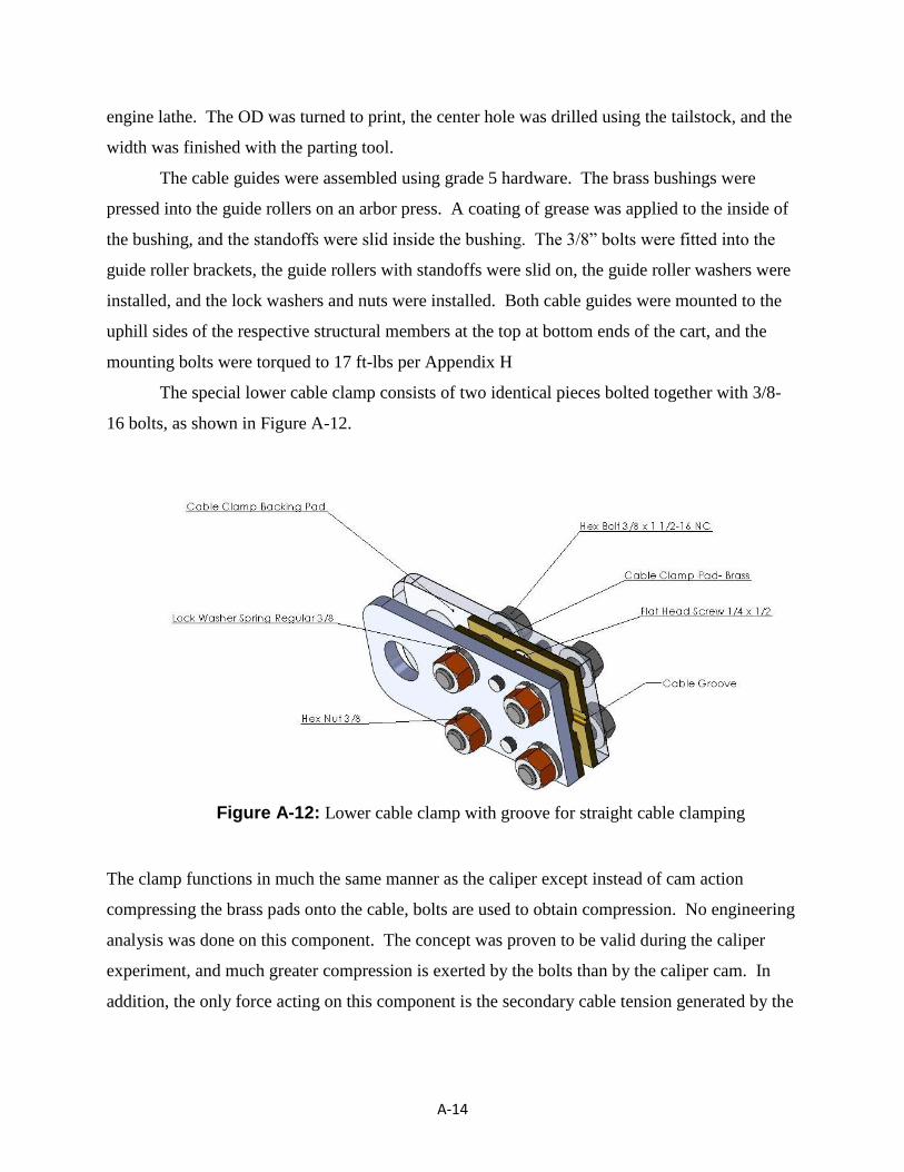
The special lower cable clamp consists of two identical pieces bolted together with 3/8-
16 bolts, as shown in Figure A-12.
The clamp functions in much the same manner as the caliper except instead of cam action
compressing the brass pads onto the cable, bolts are used to obtain compression. No engineering
analysis was done on this component. The concept was proven to be valid during the caliper
experiment, and much greater compression is exerted by the bolts than by the caliper cam. In
addition, the only force acting on this component is the secondary cable tension generated by the
Figure A-12: Lower cable clamp with groove for straight cable clamping
A-15
turnbuckle. The clamp will not see any load generated by the braking system. For these reasons,
engineering analysis was not done on this component.
Since the clamp will reside in the lower well of the tramway, and could potentially be
submersed in water, the cable clamp backing pads were made from ¼”x2” stainless steel bar
stock, and the cable clamp pads were made from 1/8” brass sheet stock. The clamp backing pads
were sawed to length in the horizontal band saw. The pad mounting holes, 3/8 bolt holes, and
the ¾” mounting hole were created on the vertical mill per drawing #3. The cable clamp pads
were machined in the same manner as the brake pads per drawing #2.
The pads were assembled to the backing plates using (2) ¼-20 x ½” flat head Phillips
screws per pad, and the assembly was loosely assembled with the 3/8” hardware shown in the
exploded view in Figure A-12.
Final Assembly
With the caliper assembly and spring force assemblies installed previously, the caliper
activation assembly can be installed. Both ¼”-20 x ½” bolts and flat washers can be installed
into the bearing blocks prior to mounting. First, the spring assembly side bearing block is
installed. Mounting the first block is accomplished using (2) 3/8-16 hex head cap screws with
flat washers on the topside, and lock washers & hex nuts on the bottom side. The brake lever
pin, with grease zerks installed, is then slid into the bearing block. The brake activation pivot
arm and E-brake handle can then be slid onto the brake lever pin, and the second bearing block
can be installed. The brake lever stop is held in place by the mounting bolts for the second
bearing block which also uses 3/8-16 bolts with flat washers on the top with lock washers and
nuts on the bottom side. The four 3/8-16 bolts were tightened to 30 ft-lbs per Appendix H
specifications for dry grade 5 bolts. Grease should be applied to both grease zerks on the ends of
the brake activation pin until grease is visibly seen squirting out both ends of the respective
lever. Significant pressure may need to be applied to the grease gun due to the tight fit of the
levers on the shaft. This condition is normal.
Once the caliper activation assembly is installed, the connecting rod between the caliper
assembly and the brake activation assembly can be installed. The ball joints are threaded onto
each end of a 5 ½” long 3/8-24 threaded rod equipped with jam nuts. One ball joint is screwed
into the small arm on the brake activation pivot arm, and the other is screwed into the caliper
A-16
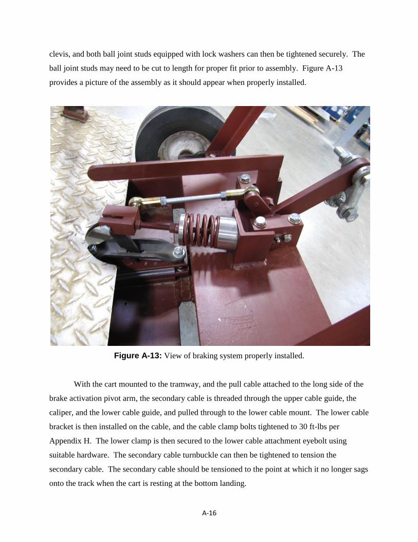
clevis, and both ball joint studs equipped with lock washers can then be tightened securely. The
ball joint studs may need to be cut to length for proper fit prior to assembly. Figure A-13
provides a picture of the assembly as it should appear when properly installed.
Figure A-13: View of braking system properly installed.
With the cart mounted to the tramway, and the pull cable attached to the long side of the
brake activation pivot arm, the secondary cable is threaded through the upper cable guide, the
caliper, and the lower cable guide, and pulled through to the lower cable mount. The lower cable
bracket is then installed on the cable, and the cable clamp bolts tightened to 30 ft-lbs per
Appendix H. The lower clamp is then secured to the lower cable attachment eyebolt using
suitable hardware. The secondary cable turnbuckle can then be tightened to tension the
secondary cable. The secondary cable should be tensioned to the point at which it no longer sags
onto the track when the cart is resting at the bottom landing.

A-17
The caliper can be aligned with the cable by making sure the caliper is compressed on the
cable, loosening, and then re-tightening the caliper mounting bolts. This will ensure the brake
pads do not wear during normal operation of the cart.
The spring in the spring assembly can be adjusted when there is no tension on the pull
cable. The easiest way to accomplish a condition with no tension in the cable is to allow the car
to rest in the lower well and operate the winch in a downward direction until the pull cable is
slack. With no tension on the pull cable, the nuts on the threaded rod for the spring force
assembly can be tightened into the upper washer until the spring is compressed to a length of 2”.
The second nut can then be used as a jam nut against the first nut as shown in figure A-13.
At this point the system is installed and ready for use.
B-1
Appendix B: Analysis
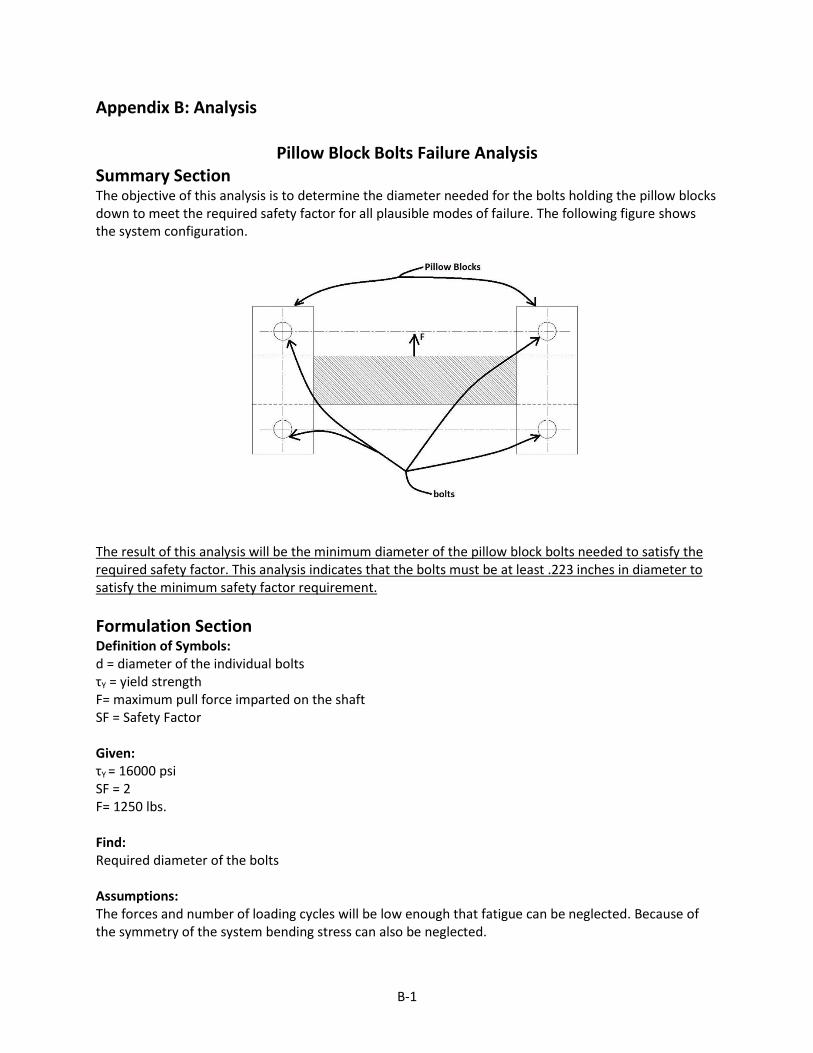
Pillow Block Bolts Failure Analysis Summary Section The objective of this analysis is to determine the diameter needed for the bolts holding the pillow blocks down to meet the required safety factor for all plausible modes of failure. The following figure shows the system configuration.
The result of this analysis will be the minimum diameter of the pillow block bolts needed to satisfy the required safety factor. This analysis indicates that the bolts must be at least .223 inches in diameter to satisfy the minimum safety factor requirement.
Formulation Section Definition of Symbols: d = diameter of the individual bolts τY = yield strength F= maximum pull force imparted on the shaft SF = Safety Factor
Given: τY = 16000 psi SF = 2 F= 1250 lbs. Find: Required diameter of the bolts Assumptions: The forces and number of loading cycles will be low enough that fatigue can be neglected. Because of the symmetry of the system bending stress can also be neglected.

B-2
Solution: Shear failure will require the largest diameter.
𝜏 =𝐹
𝐴=
𝐹
4(.25𝜋𝑑2)=
1250
𝜋𝑑2=
397.89
𝑑2
𝑑 = 397.89 ∗ 𝑆𝐹
𝜏𝑦=
397.89 ∗ 2
16000
𝑑 = 0.223 in
B-3
Caliper Activation Lever Failure Analysis
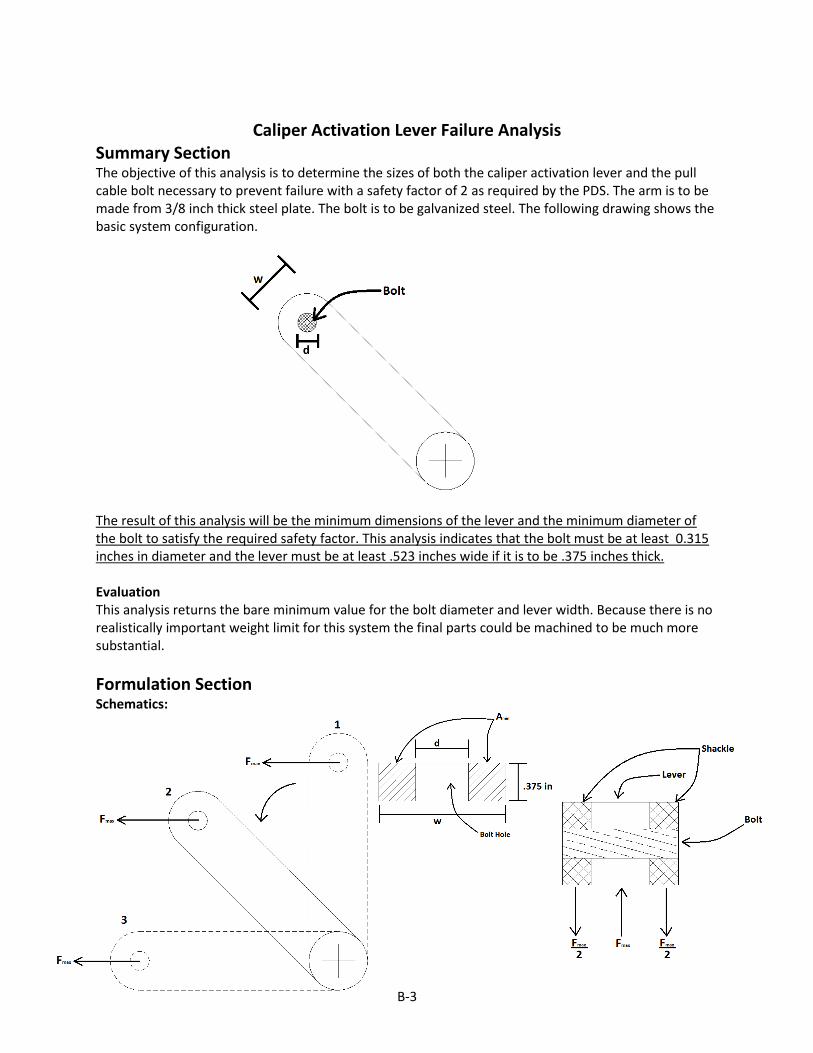
Summary Section The objective of this analysis is to determine the sizes of both the caliper activation lever and the pull cable bolt necessary to prevent failure with a safety factor of 2 as required by the PDS. The arm is to be made from 3/8 inch thick steel plate. The bolt is to be galvanized steel. The following drawing shows the basic system configuration.
The result of this analysis will be the minimum dimensions of the lever and the minimum diameter of the bolt to satisfy the required safety factor. This analysis indicates that the bolt must be at least 0.315 inches in diameter and the lever must be at least .523 inches wide if it is to be .375 inches thick. Evaluation This analysis returns the bare minimum value for the bolt diameter and lever width. Because there is no realistically important weight limit for this system the final parts could be machined to be much more substantial.
Formulation Section Schematics:

B-4
Definition of Symbols: Amin = minimum cross sectional area w = width of the lever d = diameter of the bolt Sy = yield strength Fmax= maximum pull force imparted by the cable on the lever TL = thickness of the lever SF = Safety Factor Amin,B = minimum bearing area Amin,S = minimum cross sectional area for shear loading σB =Bearing Stress σT =Stress due to tension τB = Shear Stress in the bolt τY = Yeild stress in shear dmin,B =minimum bolt diameter for bearing load dmin,S = minimum bolt diameter for shear load
Given: SY = 32000 psi TL = 0.375” SF = 2 Fmax= 1250 lbs. Find: Required width of lever, required diameter of bolt Assumptions: Stress is minimal in the lever except when it is loaded axially. Failure of the lever in tension will occur at the maximum width of the bolt hole where cross sectional area is smallest. This device will be subjected to so few load/unload cycles that fatigue failure can be neglected. Solution: Failure of the bolt due to bearing stress:
𝜎𝐵 = 𝐹𝑚𝑎𝑥𝐴𝑚𝑖𝑛 ,𝐵
=𝑆𝑦
𝑆𝐹
𝐴𝑚𝑖𝑛 ,𝐵 = 𝑇𝐿 ∗ 𝑑𝑚𝑖𝑛 ,𝐵 = .375𝑑𝑚𝑖𝑛 ,𝐵
𝐴𝑚𝑖𝑛 ,𝐵 = 𝐹𝑚𝑎𝑥 ∗ 𝑆𝐹
𝑆𝑦 =
1250 ∗ 2
32000 = .078 𝑖𝑛2
𝑑𝑚𝑖𝑛 ,𝐵 =𝐴𝑚𝑖𝑛 ,𝐵
. 375=
. 078
. 375
𝑑𝑚𝑖𝑛 ,𝐵 = 0.208 𝑖𝑛

B-5
Failure of the bolt due to shear stress:
𝜏𝐵 = . 5 ∗ 𝐹𝑚𝑎𝑥𝐴𝑚𝑖𝑛 ,𝑆
=𝜏𝑦
𝑆𝐹
𝜏𝑦 ≈𝑆𝑦
2=
32000
2= 16000
𝐴𝑚𝑖𝑛 ,𝑆 = 𝐹𝑚𝑎𝑥 ∗ 𝑆𝐹
𝜏𝑦 =
. 5 ∗ 1250 ∗ 2
16000 = 0.078 in2
𝑑𝑚𝑖𝑛 ,𝑆 = 𝐴𝑚𝑖𝑛 ,𝑆 ∗ 4
𝜋=
0.078 ∗ 4
𝜋
𝑑𝑚𝑖𝑛 ,𝑆 = 0.315 𝑖𝑛
Failure of the lever in tension:
𝐴𝑚𝑖𝑛 = .375 𝑤 − 𝑑
𝜎𝑇 = 𝐹𝑚𝑎𝑥𝐴𝑚𝑖𝑛
=𝑆𝑦
𝑆𝐹
𝐴𝑚𝑖𝑛 = 𝐹𝑚𝑎𝑥 ∗ 𝑆𝐹
𝑆𝑦
. 375 𝑤 − 𝑑 = 1250 ∗ 2
32000
𝑤 − 𝑑 =
1250 ∗ 232000
. 375= .208 in
𝑑 = 𝑑𝑚𝑖𝑛 ,𝑆 = .315 in
𝑤 = .315 + .208
𝑤 = 0.523 in
B-6
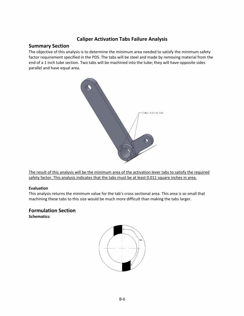
Caliper Activation Tabs Failure Analysis
Summary Section The objective of this analysis is to determine the minimum area needed to satisfy the minimum safety factor requirement specified in the PDS. The tabs will be steel and made by removing material from the end of a 1 inch tube section. Two tabs will be machined into the tube; they will have opposite sides parallel and have equal area.
The result of this analysis will be the minimum area of the activation lever tabs to satisfy the required safety factor. This analysis indicates that the tabs must be at least 0.011 square inches in area. Evaluation This analysis returns the minimum value for the tab’s cross sectional area. This area is so small that machining these tabs to this size would be much more difficult than making the tabs larger.
Formulation Section
Schematics:

B-7
Definition of Symbols: A = cross sectional area F1= Force imparted by the rod on the lever F2= Force needed on the tab to release the caliper SF = Safety Factor τ = Shear stress in the tab τY = Yield stress in shear Given: τY = 16000 psi SF = 2 F1= 100 lbs D=2 in d= 1.125 in Find: Minimum area of tab to satisfy safety factor of 2 Assumptions: The load on the tabs can be is uniform enough that it can be condensed to a point load. The tabs are not tall enough to fail due to bending stress. Shear is the only mode of failure that warrants consideration. Solution:
𝜏 = 𝐹2 𝑆𝐹 𝐴
𝐴 =𝐹2 𝑆𝐹
𝜏
𝐹1𝐷 = 2𝐹2𝑑
𝐹2 =𝐹1𝐷
2𝑑=
100 2
2 1.125
𝐹2 = 88.89 𝑙𝑏
𝐴 =𝐹2 ∗ 𝑆𝐹
𝜏=
(88.89 ∗ 2)
16000
𝐴 = .011 𝑖𝑛2
B-8
Caliper Activation Shaft Failure Analysis
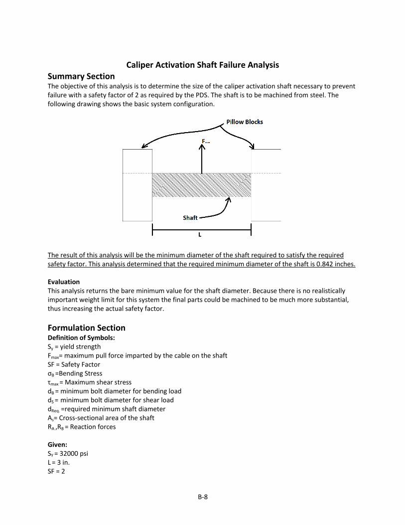
Summary Section The objective of this analysis is to determine the size of the caliper activation shaft necessary to prevent failure with a safety factor of 2 as required by the PDS. The shaft is to be machined from steel. The following drawing shows the basic system configuration.
The result of this analysis will be the minimum diameter of the shaft required to satisfy the required safety factor. This analysis determined that the required minimum diameter of the shaft is 0.842 inches. Evaluation This analysis returns the bare minimum value for the shaft diameter. Because there is no realistically important weight limit for this system the final parts could be machined to be much more substantial, thus increasing the actual safety factor.
Formulation Section Definition of Symbols: Sy = yield strength Fmax= maximum pull force imparted by the cable on the shaft SF = Safety Factor σB =Bending Stress τmax = Maximum shear stress dB = minimum bolt diameter for bending load dS = minimum bolt diameter for shear load dReq. =required minimum shaft diameter As= Cross-sectional area of the shaft RA ,RB = Reaction forces Given: SY = 32000 psi L = 3 in. SF = 2
B-9
Fmax = 1250 lbs. Find: dReq
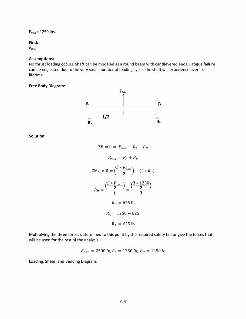
Assumptions: No thrust loading occurs. Shaft can be modeled as a round beam with cantilevered ends. Fatigue failure can be neglected due to the very small number of loading cycles the shaft will experience over its lifetime. Free Body Diagram:
Solution:
Σ𝐹 = 0 = 𝐹𝑚𝑎𝑥 − 𝑅𝐴 − 𝑅𝐵
𝐹𝑚𝑎𝑥 = 𝑅𝐴 + 𝑅𝐵
ΣMA = 0 = 𝐿 ∗ 𝐹𝑚𝑎𝑥
2 − 𝐿 ∗ 𝑅𝐵
𝑅𝐵 = 𝐿 ∗ 𝐹𝑚𝑎𝑥
2
𝐿=
3 ∗ 12502
3
𝑅𝐵 = 625 lb
𝑅𝐴 = 1250 − 625
RA = 625 lb
Multiplying the three forces determined to this point by the required safety factor give the forces that will be used for the rest of the analysis:
𝐹𝑚𝑎𝑥 = 2500 𝑙𝑏,𝑅𝐴 = 1250 𝑙𝑏, 𝑅𝐵 = 1250 𝑙𝑏 Loading, Shear, and Bending Diagram:
B-10
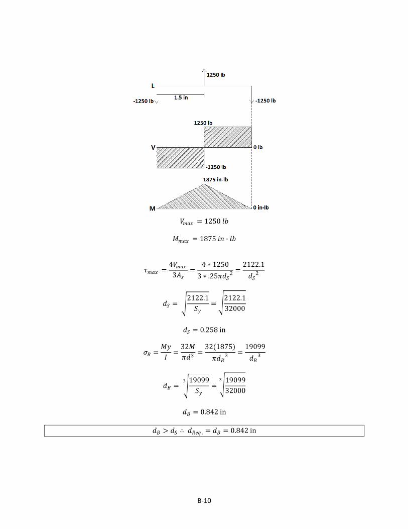
𝑉𝑚𝑎𝑥 = 1250 𝑙𝑏
𝑀𝑚𝑎𝑥 = 1875 𝑖𝑛 ∙ 𝑙𝑏
𝜏𝑚𝑎𝑥 =4𝑉𝑚𝑎𝑥
3𝐴𝑠=
4 ∗ 1250
3 ∗ .25𝜋𝑑𝑆2 =
2122.1
𝑑𝑆2
𝑑𝑆 = 2122.1
𝑆𝑦=
2122.1
32000
𝑑𝑆 = 0.258 in
𝜎𝐵 =𝑀𝑦
𝐼=
32𝑀
𝜋𝑑3=
32(1875)
𝜋𝑑𝐵3 =
19099
𝑑𝐵3
𝑑𝐵 = 19099
𝑆𝑦
3
= 19099
32000
3
𝑑𝐵 = 0.842 in
𝑑𝐵 > 𝑑𝑆 ∴ 𝑑𝑅𝑒𝑞 . = 𝑑𝐵 = 0.842 in
B-11
Brake Cable Failure Analysis
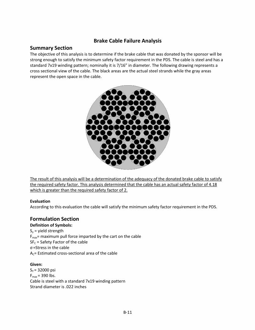
Summary Section The objective of this analysis is to determine if the brake cable that was donated by the sponsor will be strong enough to satisfy the minimum safety factor requirement in the PDS. The cable is steel and has a standard 7x19 winding pattern; nominally it is 7/16” in diameter. The following drawing represents a cross sectional view of the cable. The black areas are the actual steel strands while the gray areas represent the open space in the cable.
The result of this analysis will be a determination of the adequacy of the donated brake cable to satisfy the required safety factor. This analysis determined that the cable has an actual safety factor of 4.18 which is greater than the required safety factor of 2. Evaluation According to this evaluation the cable will satisfy the minimum safety factor requirement in the PDS.
Formulation Section Definition of Symbols: Sy = yield strength Fmax= maximum pull force imparted by the cart on the cable SFC = Safety Factor of the cable σ =Stress in the cable AC= Estimated cross-sectional area of the cable Given: SY = 32000 psi Fmax = 390 lbs. Cable is steel with a standard 7x19 winding pattern Strand diameter is .022 inches

B-12
Find: Actual safety factor of cable Assumptions: The cross sectional area of the cable can be approximated by summing the cross sectional areas of the strands that comprise the cable. Solution: Approximate cross-sectional area of the cable: The cable is made up of 7 bundles with 19 strands per bundle. The approximate area can be calculated as follows:
𝐴𝐶 = 𝑆𝑡𝑟𝑎𝑛𝑑 𝑎𝑟𝑒𝑎 ∗ #𝑜𝑓 𝑏𝑢𝑛𝑑𝑙𝑒𝑠 ∗ # 𝑜𝑓 𝑠𝑡𝑟𝑎𝑛𝑑𝑠 𝑝𝑒𝑟 𝑏𝑢𝑛𝑑𝑙𝑒
𝐴𝐶 = .25𝜋 . 0222 (7)(19)
𝐴𝐶 = .051 in2 This approximate area can then be used to find the actual safety factor of the cable.
𝜎 =𝐹𝑚𝑎𝑥𝐴𝐶
=390
. 051= 7647.1 psi
𝑆𝐹𝐶 =𝑆𝑦
𝜎=
32000
7647.1
𝑆𝐹𝐶 = 4.18

B-13
Connecting Rod Failure Analysis
Summary Section The objective of this analysis is to determine the diameter needed to make the connecting rod meet the required minimum safety factor for all reasonably plausible modes of failure. The rod that will be used is threaded steel. The following drawing shows the system.
The result of this analysis will be the minimum diameter of the connecting rod to satisfy the required safety factor. This analysis indicates that the rod must be at least 0.089 inches in diameter.
Formulation Section Definition of Symbols: d = diameter of the bolt Sy = yield strength F= maximum pull force imparted on the rod SF = Safety Factor
Given: SY = 32000 psi SF = 2 F= 100 lbs. Find: Required diameter of the rod Assumptions: The forces and number of loading cycles will be low enough that fatigue can be neglected. It can also be assumed that buckling can be neglected. Solution:
𝜎 =𝐹
𝐴=
𝐹
. 25𝜋𝑑2=
100
. 25𝜋𝑑2=
127.324
𝑑2

B-14
𝑑 = 127.324 ∗ 𝑆𝐹
𝑆𝑦=
127.324 ∗ 2
32000
𝑑 = 0.089 in
B-15
Force applied to braking cable versus time to stop tram cart
Summary Section
The goal of this analysis is to provide the stopping force needed to be generated in the
secondary brake cable by the brake caliper to stop the motion of the cart over a change in time.
This analysis is needed to determine the average acceleration of the tram cart versus the tension
created in the braking cable.
The results of this analysis will be used in combination with Appendix C to determine the
input force needed to be applied to the brake caliper versus the force required to be applied to the
brake cable by the caliper to keep stopping acceleration of the cart within acceptable limits.
The results will be expressed in graphical form with force in lbs corresponding to elapsed
time in seconds.
Evaluation Section
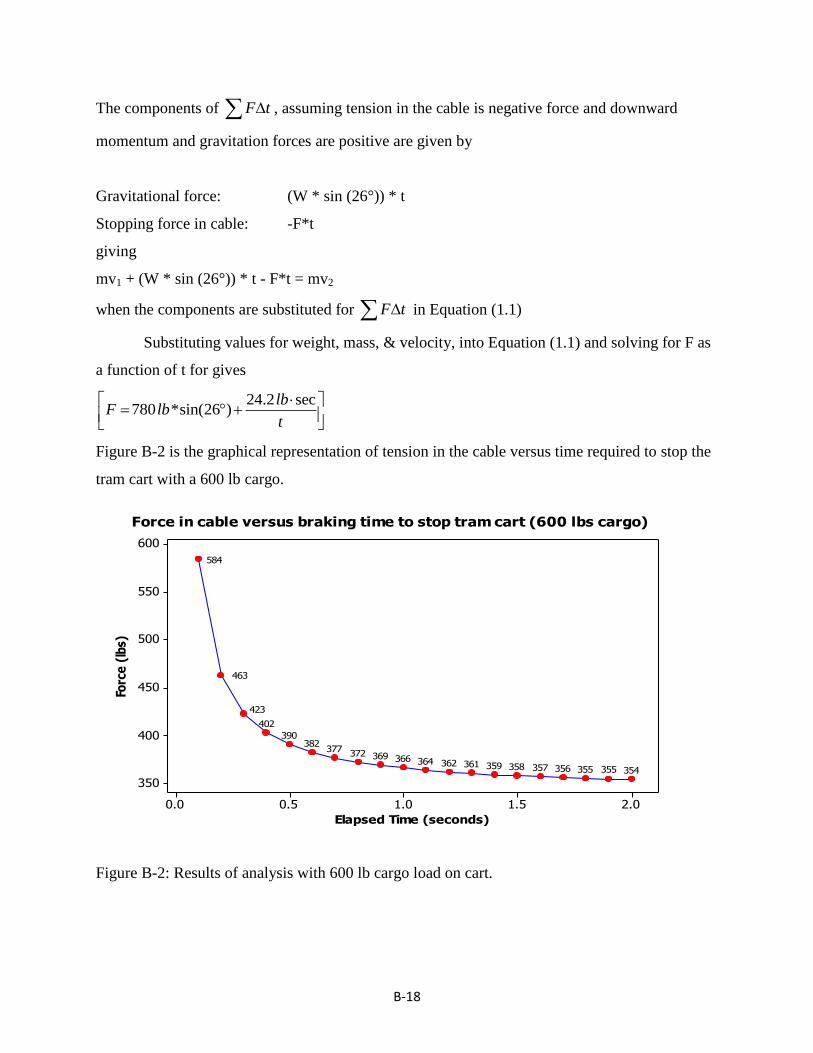
The graphical results shown in Figure B-2 indicate that a minimum force of
approximately 354 lbf tension is required to be applied to the cable to stop the cart when the cart
is fully loaded. This minimum is noted by the flattening of the slope of the the graph in Figure
B-2. The force value of 354 lbf needed to stop the fully loaded cart will most likely exceed the
PDS allowable stopping acceleration when the tram cart is partially loaded. Mitigating factors
for this issue may exist since the time for the cart to reach final velocity on empty startup is
much less than when fully loaded, thereby increasing the possible acceleration value that can be
used for the braking system when the cart has a load that is less than full capacity. Additional
design review sessions with the product sponsor determined this is acceptable.
This analysis uses the principles of impulse and momentum. The analysis assumes that
stopping of the tram cart occurs in a short enough period of time, and large enough changes in
momentum occur that the forces involved can be called impulsive forces. The result also
assumes the starting acceleration is 2 ft/sec by assuming the cart is at its final velocity of 1 ft/sec
in 0.5 seconds as attempted to be measured with a stop watch.
B-16
Formulation Section
Given:
1. Initial velocity = v1 = 1 ft/sec
2. Final velocity = v2 = 0 ft/sec
3. W = weight of fully loaded cart (600 lbs cargo + 180 lb cart) = 780 lbs
4. Angle of departure from horizontal for tramway is Q =26 degrees
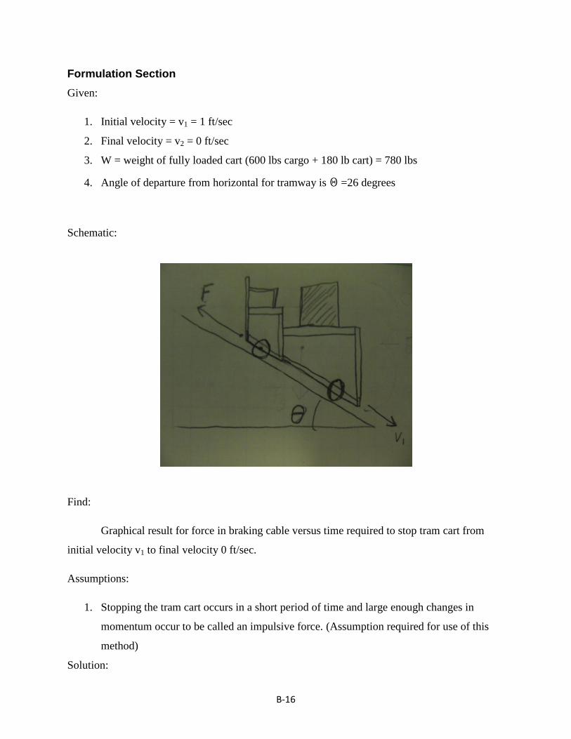
Schematic:
Find:
Graphical result for force in braking cable versus time required to stop tram cart from
initial velocity v1 to final velocity 0 ft/sec.
Assumptions:
1. Stopping the tram cart occurs in a short period of time and large enough changes in
momentum occur to be called an impulsive force. (Assumption required for use of this
method)
Solution:
B-17
Applying the principles of impulse and momentum, the following equation can be used to
solve for force in the braking cable, F, as a function of change in time, t.
1 2mv F t mv (0.1)
where:
m = mass of moving cart
v1 = initial velocity
F t = sum of forces acting on cart multiplied by change in time
v2 = final velocity
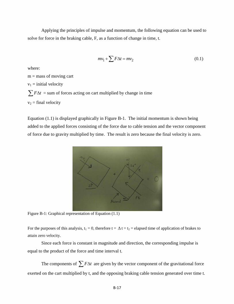
Equation (1.1) is displayed graphically in Figure B-1. The initial momentum is shown being
added to the applied forces consisting of the force due to cable tension and the vector component
of force due to gravity multiplied by time. The result is zero because the final velocity is zero.
Figure B-1: Graphical representation of Equation (1.1)
For the purposes of this analysis, t1 = 0, therefore t = t = t2 = elapsed time of application of brakes to
attain zero velocity.
Since each force is constant in magnitude and direction, the corresponding impulse is
equal to the product of the force and time interval t.
The components of F t are given by the vector component of the gravitational force
exerted on the cart multiplied by t, and the opposing braking cable tension generated over time t.
B-18
The components of F t , assuming tension in the cable is negative force and downward
momentum and gravitation forces are positive are given by
Gravitational force: (W * sin (26°)) * t
Stopping force in cable: -F*t
giving
mv1 + (W * sin (26°)) * t - F*t = mv2
when the components are substituted for F t in Equation (1.1)
Substituting values for weight, mass, & velocity, into Equation (1.1) and solving for F as
a function of t for gives
24.2 sec780 *sin(26 )
lbF lb
t
Figure B-2 is the graphical representation of tension in the cable versus time required to stop the
tram cart with a 600 lb cargo.
2.01.51.00.50.0
600
550
500
450
400
350
Elapsed Time (seconds)
Forc
e (
lbs)
354355355356357358359361362364366369372377
382390
402
423
463
584
Force in cable versus braking time to stop tram cart (600 lbs cargo)
Figure B-2: Results of analysis with 600 lb cargo load on cart.

B-19
References:
[1]: Ferdinand P. Beer, E. Russell Johnston, Jr., William E. Clausen, Vector Mechanics for
Engineers, Dynamics, 8th
Edition, McGraw Hill, 2007, pp. 805-809
C-1
Appendix C: Experiments
Caliper Force Evaluation Experiment
Background:
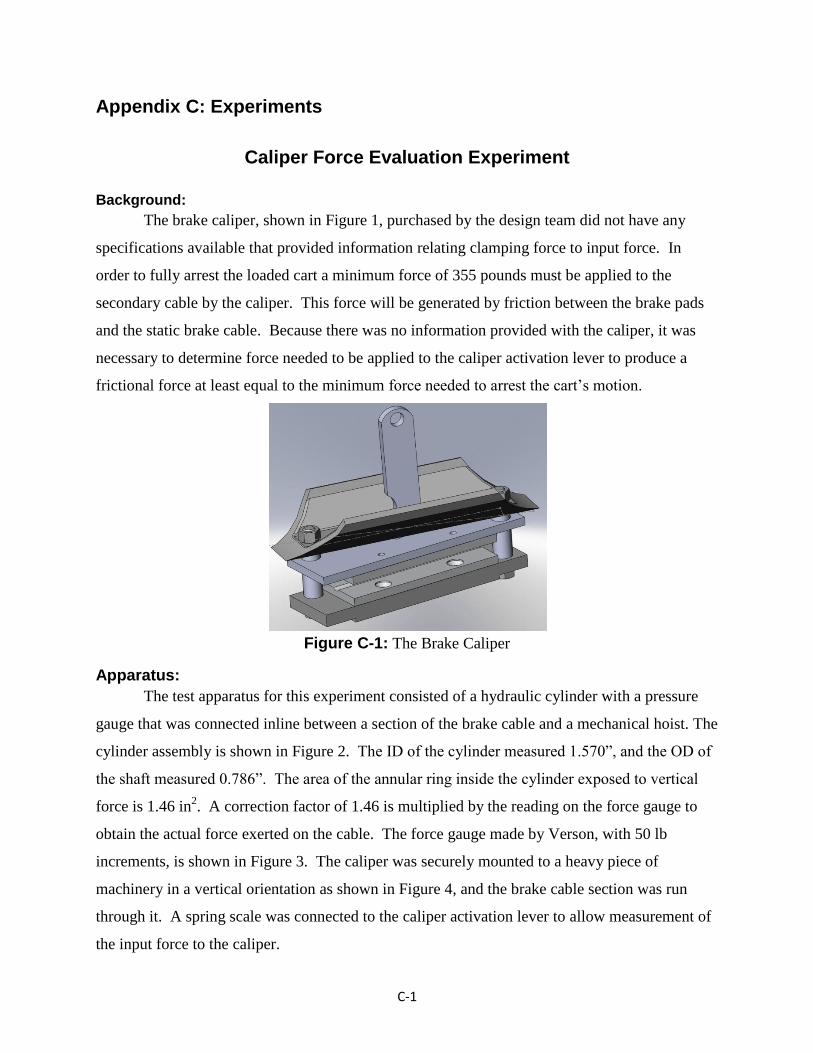
The brake caliper, shown in Figure 1, purchased by the design team did not have any
specifications available that provided information relating clamping force to input force. In
order to fully arrest the loaded cart a minimum force of 355 pounds must be applied to the
secondary cable by the caliper. This force will be generated by friction between the brake pads
and the static brake cable. Because there was no information provided with the caliper, it was
necessary to determine force needed to be applied to the caliper activation lever to produce a
frictional force at least equal to the minimum force needed to arrest the cart’s motion.
Figure C-1: The Brake Caliper
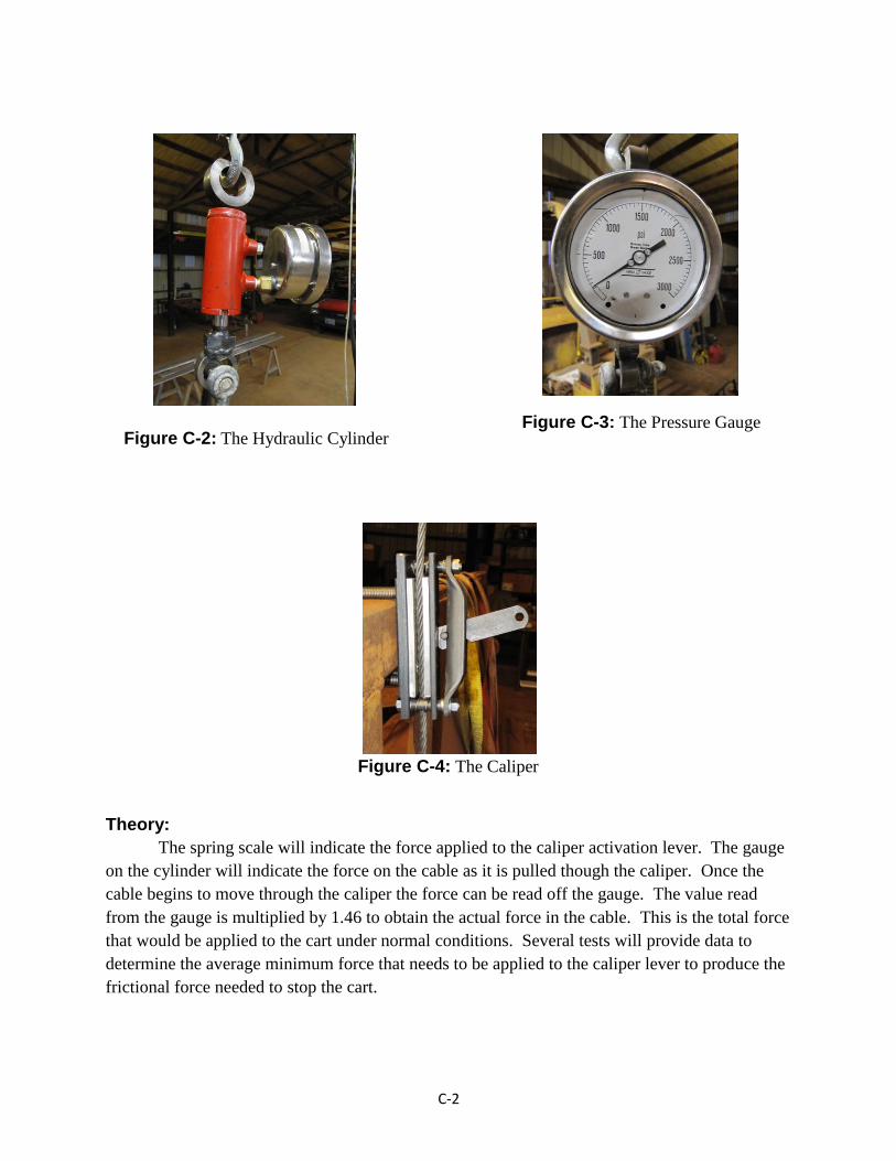
Apparatus:
The test apparatus for this experiment consisted of a hydraulic cylinder with a pressure
gauge that was connected inline between a section of the brake cable and a mechanical hoist. The
cylinder assembly is shown in Figure 2. The ID of the cylinder measured 1.570”, and the OD of
the shaft measured 0.786”. The area of the annular ring inside the cylinder exposed to vertical
force is 1.46 in2. A correction factor of 1.46 is multiplied by the reading on the force gauge to
obtain the actual force exerted on the cable. The force gauge made by Verson, with 50 lb
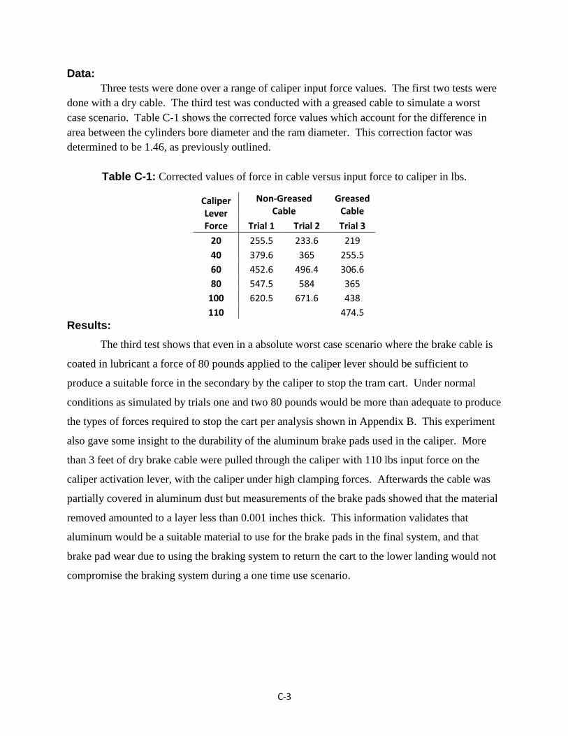
increments, is shown in Figure 3. The caliper was securely mounted to a heavy piece of
machinery in a vertical orientation as shown in Figure 4, and the brake cable section was run
through it. A spring scale was connected to the caliper activation lever to allow measurement of
the input force to the caliper.
C-2
Theory:
The spring scale will indicate the force applied to the caliper activation lever. The gauge
on the cylinder will indicate the force on the cable as it is pulled though the caliper. Once the
cable begins to move through the caliper the force can be read off the gauge. The value read
from the gauge is multiplied by 1.46 to obtain the actual force in the cable. This is the total force
that would be applied to the cart under normal conditions. Several tests will provide data to
determine the average minimum force that needs to be applied to the caliper lever to produce the
frictional force needed to stop the cart.
Figure C-3: The Pressure Gauge Figure C-2: The Hydraulic Cylinder
Figure C-4: The Caliper
C-3
Data:
Three tests were done over a range of caliper input force values. The first two tests were
done with a dry cable. The third test was conducted with a greased cable to simulate a worst
case scenario. Table C-1 shows the corrected force values which account for the difference in
area between the cylinders bore diameter and the ram diameter. This correction factor was
determined to be 1.46, as previously outlined.
Table C-1: Corrected values of force in cable versus input force to caliper in lbs.
Caliper Lever Force
Non-Greased Cable
Greased Cable
Trial 1 Trial 2 Trial 3
20 255.5 233.6 219
40 379.6 365 255.5
60 452.6 496.4 306.6
80 547.5 584 365
100 620.5 671.6 438
110
474.5
Results:
The third test shows that even in a absolute worst case scenario where the brake cable is
coated in lubricant a force of 80 pounds applied to the caliper lever should be sufficient to
produce a suitable force in the secondary by the caliper to stop the tram cart. Under normal
conditions as simulated by trials one and two 80 pounds would be more than adequate to produce
the types of forces required to stop the cart per analysis shown in Appendix B. This experiment
also gave some insight to the durability of the aluminum brake pads used in the caliper. More
than 3 feet of dry brake cable were pulled through the caliper with 110 lbs input force on the
caliper activation lever, with the caliper under high clamping forces. Afterwards the cable was
partially covered in aluminum dust but measurements of the brake pads showed that the material
removed amounted to a layer less than 0.001 inches thick. This information validates that
aluminum would be a suitable material to use for the brake pads in the final system, and that
brake pad wear due to using the braking system to return the cart to the lower landing would not
compromise the braking system during a one time use scenario.

D-1
Appendix D: Bill of Materials
Part Name/ Part Number Quantity Material Make (M)/ Buy (B)Drawing Number/
SourceCost Total
Hand Brake Assembly 1
Bearing Block 2 Steel M 20 Donated Donated
Brake Activation Pivot Arm 1 Steel M 12 Donated Donated
Brake Lever Pin 1 Steel M 24 Donated Donated
Brake Lever Stop 1 Steel M 21 Donated Donated
E-Brake Handle 1 Steel M 11 Donated Donated
1/4"- 20 x 1/2" Hex Head Cap Screw Gr.5 2 Steel B N/A Donated Donated
1/4" Flat Washer 2 Steel B N/A Donated Donated
3/8" -16 x 3.5 Head Head Cap Screw Gr.5 4 Steel B N/A Donated Donated
3/8" Flat Washer 4 Steel B N/A Donated Donated
3/8 Spring Type Lock Washer 4 Steel B N/A Donated Donated
3/8-16 Hex Nut 4 Steel B N/A Donated Donated
1/4"- 28 Grease Zerk 2 Steel B N/A Donated Donated
Cable Clamp Assembly 1
Cable Clamp Backing Pad 2 Stainless Steel M 3 Donated Donated
Cable Clamp Pad 2 Brass M 2 Donated Donated
Hex Bolt 3/8"-16 x 1 1/2" 4 Steel B N/A Donated Donated
Hex Nut 3/8" - 16 4 Steel B N/A Donated Donated
3/8" Flat Washer 4 Steel B N/A Donated Donated
3/8" Lock Washer Spring Type 4 Steel B N/A Donated Donated
Flat Head Screw 1/4 x 1/2 2 Steel B N/A Donated Donated
Parking Brake Caliper 5206- AP- 10024 1 Steel B All-Pro Off Road, Inc $89.00 $89.00
Spacer 1/2" 1 Steel M 8 Donated Donated
Lower Backing Pad 1 Steel M 17 Donated Donated
Brake Pad Backing Plate 2 Steel M 18 Donated Donated
Brake Pad 2 Aluminum M 19 Donated Donated
1/4"- 20 x 3/4" Flat Head Phillips Screw 4 Steel B N/A Donated Donated
1/4"-20 x 1/2" Flat Head Phillips Screw 4 Steel B N/A Donated Donated
3/8"-16 x 2.5" Hex Head Cap Screw Gr.5 2 Steel B N/A Donated Donated
3/8" - 16 Hex Nut 2 Steel B N/A Donated Donated
3/8" Flat Washer 2 Steel B N/A Donated Donated
3/8 Flat Washer 0.562" OD 6 Stainless Steel B N/A Donated Donated
Spring Assembly 1
Large Spring Base 1 Stainless Steel M 1 Donated Donated
Large Spring Top Washer 1 Stainless Steel M 14 Donated Donated
3/8" -16 x 8.75" Threaded Rod 1 Steel M N/A Donated Donated
Square Caliper Clevis 1 Steel M 10 Donated Donated
Spring MMC#96485K131 1 Steel B McMASTER-CARR.com $8.40 $8.40
3/8" - 16 Hex Nut 3 Steel B N/A Donated Donated
3/8"- 16 x 1.75" Hex Head Cap Screw Gr.5 1 Steel B N/A Donated Donated
1/4" -20 x 1.5" Socket Head Cap Screw 2 Steel B N/A Donated Donated
Conneting Rod 1
Self-Lube Bronze Race Ball Joint Rod End 2 Various B McMASTER-CARR $7.03 $14.06
3/8 " - 24 x 5.5 " Threaded Rod 1 Steel B N/A $2.46 $2.46
3/8" - 24 Hex Nut 2 Steel B N/A Donated Donated
3/8" Flat Washer Spring Type 2 Steel B N/A Donated Donated
Cable Guide Roller Assembly 2
Guide Roller Bracket 2 Steel M 22 Donated Donated
Guide Roller Bushing 4 Steel M 23 Donated Donated
Guide Roller Washer 4 Steel M 16 Donated Donated
Guide Roller 4 Steel M 15 Donated Donated
Stand off 4 Steel M 7 Donated Donated
5/16" - 18 x 1/2" Hex Head Cap Screw 4 Steel B N/A Donated Donated
3/8" - 16 x 1 1/4" Hex Head Cap Screw 4 Steel B N/A Donated Donated
3/8 " Lock Washer 4 Steel B N/A Donated Donated
3/8" Hex Nut 4 Steel B N/A Donated Donated

E-1
Appendix E: Operation & Maintenance Manual
Operation Manual: For system assembly instruction please see Appendix A. This operation manual assumes the
system is fully assembled and adjusted prior to starting operation.
Automatic Operation:
Under normal operation conditions the braking system will automatically engage in the
event of pull cable breakage or loss of tension on the cable due to winch malfunction.
Engagement of the braking system will result in stoppage of the tram cart
Normal operation can automatically resume when tension is applied to the pull cable by
the winch system.
Manual Operation
Manual deactivation of the braking system is accomplished by lifting the E-brake handle
after automatic operation of the braking system has occurred.
The speed of descent is controlled by the amount the E-brake handle is lifted. Caution
should be exercised to maintain a low rate of descent during manual operation by
moderating the force applied to the E-brake handle.
Maintenance Manual:
Warning: This braking system is for emergency use only, and if proper maintenance is
performed on the pull cable, the braking system should never need to be activated. A regular
maintenance program for inspecting the pull cable is critical to prevent risk of injury to people or
cargo that may use the tram associated with this braking system.
Warning: If the braking system is activated, the brake pads should be inspected for proper cable
groove depth prior to further use of the tram system. Maximum groove depth is 0.140” for either
brake pad. If groove depth is exceeded, replace brake pads prior to further use of the tram
system.

E-2
Normal Maintenance:
Semi Annual PM:
Inspect secondary cable for frayed or damaged areas. If any damage is found, replace
secondary cable immediately. See Appendix A for secondary cable installation
instructions.
Grease (2) locations on brake lever pin. See Appendix A, Figure A-13 for grease Zerk
locations. (Note: 2nd
Zerk is on opposite end of brake lever pin)
Grease (4) guide rollers. Loosen, and remove one guide roller bolt. Lift guide roller off
cable. Slide standoff out of bushing. Inspect components for wear, if significant wear is
observed, replace component. Otherwise, apply a liberal coating of a suitable water
repellent grease to OD of standoff, ID of bushing, and sides of guide roller. Replace
components as removed. Tighten bolt to 15 ft-lbs. Repeat procedure for the other (3)
guide rollers.
Grease cam point where caliper activation lever meets upper backing pad.
Check for proper motion of E-brake handle and brake activation pivot arm by using E-
brake handle to move brake activation pivot arm. If arms do not move freely, inspect for
reason and perform necessary repairs.
Inspect all other system parts for damage. If any damage is noted, replace component
immediately.
Bi-Annual Maintenance:
Perform all items in Semi Annual PM
Check free length of activation spring. Free length should be 3” (nominal). If free
length is less than 2.85”, replace activation spring. (See Appendix D for spring part #)
If spring length is acceptable, re-tighten spring to a position 1” shorter than free length.
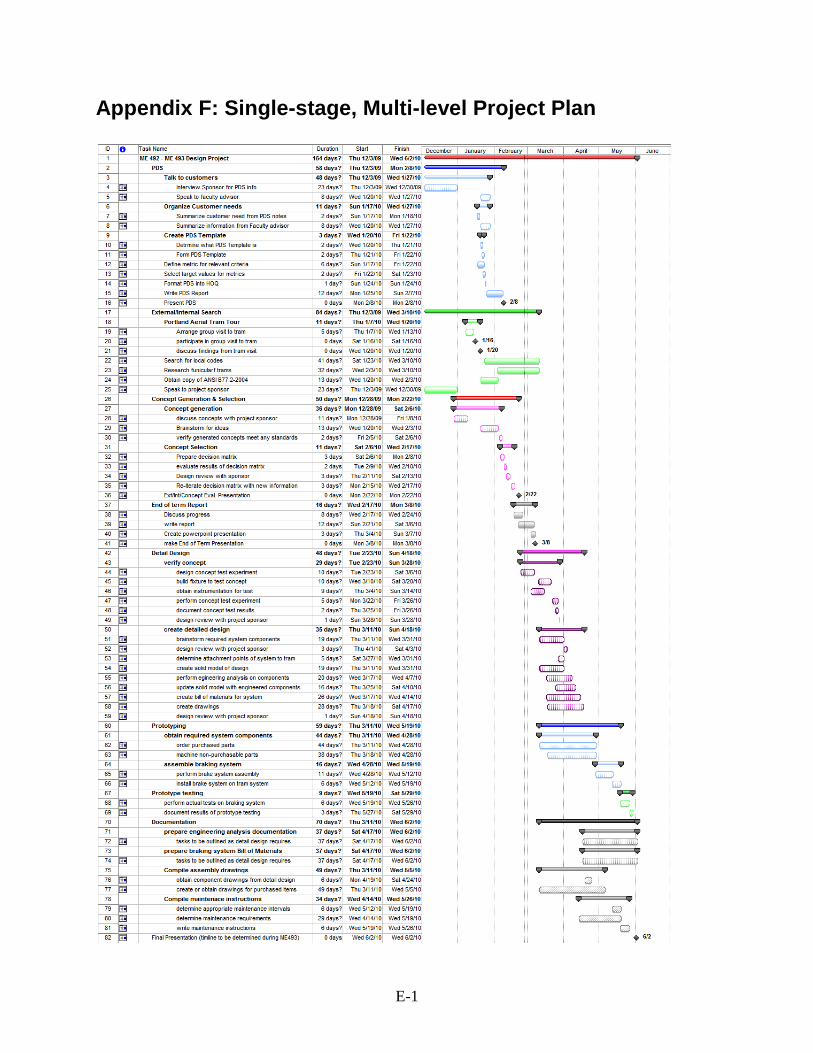
E-1
Appendix F: Single-stage, Multi-level Project Plan

G-1
Appendix G: Product Design Specification
The most important PDS elements for this project are:
Providing a means to arrest the motion of the cart in the event of a pull cable or winch
malfunction. This design element is the primary reason for this entire project. The
safety of passengers and cargo depend on the operation of a braking system in the event
of a winch or cable malfunction.
Reliability is of paramount concern with this project because the safety of people is in
question.
The system must be designed to stop a total cart weight of 600 – 800 lbs.
The braking system must be completely mechanical.
Capturing the tram cart to the tram structure.
Documentation including a regular inspection and maintenance schedule, Bill of
Materials, component drawings, and operating instructions need to be provided to the
project sponsor.
The complete PDS can be found on the following pages.

G-2
Performance Priority: High: Medium: Low:
Environment Project Requirement Engineering Metric Target Value Target Basis Verification Method
Life in Service years 20 years typical lifetime of mechanical
assembly
Protoype
Operation in all weather conditions
anti friction components protected
from elements
Zero water contamination of
bearings and other anti friction
elements
Zdenek Prototype
Auto stop or Auto descend on loss of mechanical control of tram cart
ft / sec
0 – 2 ft/sec Zdenek set distance traveled over time taken to travel set distance
Stopping acceleration not to exceed startup acceleration
ft / sec2 TBD Zdenek moving velocity to zero velocity difference over time taken to change velocity
Required cart load capacity pounds 150-180 lb cart plus
400-600 lb cargo
Zdenek Testing system with known weight on cart after assembly of prototype
Braking mechanism is mechanically operated (non-electrical)
yes / no yes Zdenek Prototype
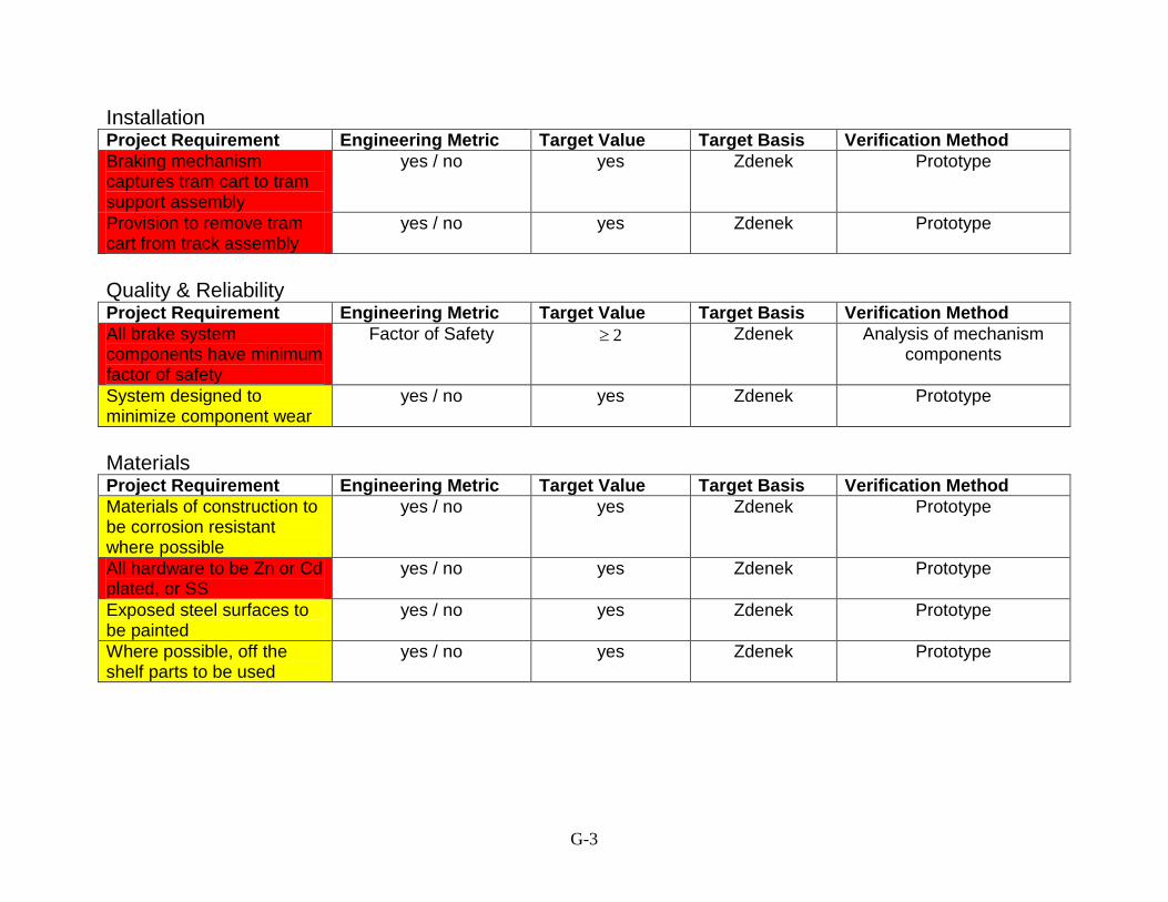
G-3
Installation Project Requirement Engineering Metric Target Value Target Basis Verification Method
Braking mechanism captures tram cart to tram support assembly
yes / no yes Zdenek Prototype
Provision to remove tram cart from track assembly
yes / no yes Zdenek Prototype
Quality & Reliability Project Requirement Engineering Metric Target Value Target Basis Verification Method
All brake system components have minimum factor of safety
Factor of Safety 2 Zdenek Analysis of mechanism components
System designed to minimize component wear
yes / no yes Zdenek Prototype
Materials Project Requirement Engineering Metric Target Value Target Basis Verification Method
Materials of construction to be corrosion resistant where possible
yes / no yes Zdenek Prototype
All hardware to be Zn or Cd plated, or SS
yes / no yes Zdenek Prototype
Exposed steel surfaces to be painted
yes / no yes Zdenek Prototype
Where possible, off the shelf parts to be used
yes / no yes Zdenek Prototype

G-4
Maintenance Project Requirement Engineering Metric Target Value Target Basis Verification Method
All lubrication points easily accessible
yes / no yes self Prototype
Attachment points for any guards should be easily accessible
yes / no yes self Prototype
Ergonomics Project Requirement Engineering Metric Target Value Target Basis Verification Method
If braking system is designed to stop cart on tram way during an event, a conveniently placed, controlled manual release is provided
yes / no yes Zdenek Prototype
Applicable Codes & Standards Project Requirement Engineering Metric Target Value Target Basis Verification Method
Where possible comply with ANSI B77.2-2004 (yet to be obtained)
yes / no yes Zdenek Prototype
Size and Shape Project Requirement Engineering Metric Target Value Target Basis Verification Method
Braking system fits under deck of tram cart
yes or no yes Zdenek visual
unsealed components remain above waterline of lower well.
yes or no yes Zdenek visual
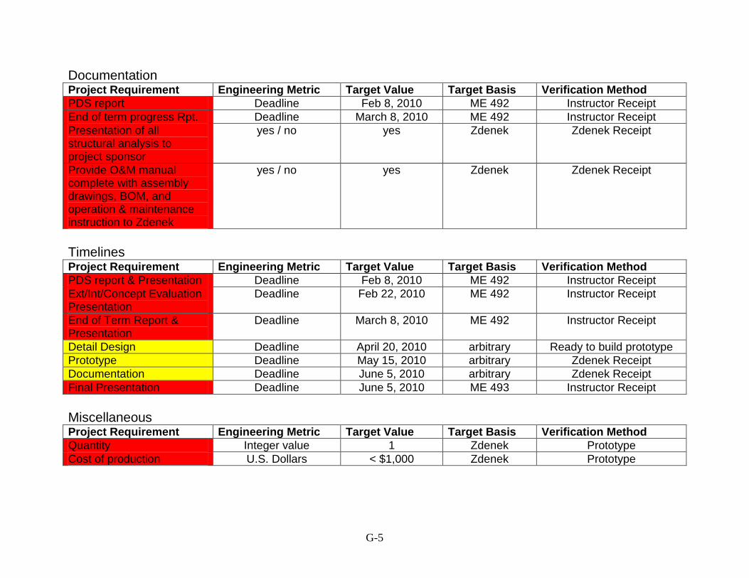
G-5
Documentation Project Requirement Engineering Metric Target Value Target Basis Verification Method
PDS report Deadline Feb 8, 2010 ME 492 Instructor Receipt
End of term progress Rpt. Deadline March 8, 2010 ME 492 Instructor Receipt
Presentation of all structural analysis to project sponsor
yes / no yes Zdenek Zdenek Receipt
Provide O&M manual complete with assembly drawings, BOM, and operation & maintenance instruction to Zdenek
yes / no yes Zdenek Zdenek Receipt
Timelines Project Requirement Engineering Metric Target Value Target Basis Verification Method
PDS report & Presentation Deadline Feb 8, 2010 ME 492 Instructor Receipt
Ext/Int/Concept Evaluation Presentation
Deadline Feb 22, 2010 ME 492 Instructor Receipt
End of Term Report & Presentation
Deadline March 8, 2010 ME 492 Instructor Receipt
Detail Design Deadline April 20, 2010 arbitrary Ready to build prototype
Prototype Deadline May 15, 2010 arbitrary Zdenek Receipt
Documentation Deadline June 5, 2010 arbitrary Zdenek Receipt
Final Presentation Deadline June 5, 2010 ME 493 Instructor Receipt
Miscellaneous Project Requirement Engineering Metric Target Value Target Basis Verification Method
Quantity Integer value 1 Zdenek Prototype
Cost of production U.S. Dollars < $1,000 Zdenek Prototype

H-1
Appendix H: Suggested bolt tightening torque
SAE Grade 2 Bolts SAE Grde 5 Bolts SAE Grade 7 SAE Grade 8
Size
Bolt
Diam.
D(in.)
Stress
Area
A(in²)
Tensile
Strength
min psi
Proof
Load
psi
Clamp
Load
P (lb)
T
Dry
Tor-
que
Lub.
Tensile
Strength
Proof
Load
Clamp
Load
T
Dry
Tor
-que
Lub.
Clamp
Load
Tight
Dry
Tor-
que
Lub.
Clamp
Load
T
Dry
Tor-
que
Lub. 1/4-20 0.2500 0.0318 1320 66 49 2020 96 75 2500 120 96 2860 144 108
1/4-28 0.2500 0.0364 1500 76 56 2320 120 86 2880 144 108 3280 168 120
5/16-18 0.3125 0.0524 2160 11 8 3340 17 13 4120 21 16 4720 25 18
5/16-24 0.3125 0.0580 2400 12 9 3700 19 14 4580 24 18 5220 25 20
3/8-16 0.3750 0.0775 3200 20 15 4940 30 23 6100 40 30 7000 45 35
3/8-24 0.3750 0.0878 3620 23 17 5600 35 25 6900 41 30 7900 50 35
7/16-14 0.4375 0.1063 4380 30 24 6800 50 35 8400 60 45 9550 70 55
7/16-20 0.4375 0.1187 4900 35 25 7550 55 40 9350 70 50 10700 80 60
1/2-13 0.5000 0.1419 5840 50 35 9050 75 55 11200 95 70 12750 110 80
1/2-13 0.5000 0.1599 6600 55 40 10700 90 65 12600 100 80 14400 120 90
9/16-12 0.5625 0.1820 7500 70 55 11600 110 80 14350 135 100 16400 150 110
9/16-18 0.5625 0.2030 8400 80 60 12950 120 90 16000 150 110 18250 170 130
5/8-11 0.6250 0.2260 9300 100 75 14400 150 110 17800 190 140 20350 220 170
5/8-18 0.6250 0.2560 10600 110 85 16300 170 130 20150 210 160 23000 240 180
3/4-10 0.7500 0.3340 13800 175 130 21300 260 200 26300 320 240 30100 380 280
3/4-16 0.7500 0.3730 15400 195 145 23800 300 220 29400 360 280 33600 420 320
7/8-9 0.8750 0.4620 60,000 33,000 11400 165 125 29400 430 320 36400 520 400 41600 600 460
7/8-14 0.8750 0.5090 12600 185 140 32400 470 350 40100 580 440 45800 660 500
1-8 1.0000 0.6060 15000 250 190 38600 640 480 47700 800 600 54500 900 680
1-12 1.0000 0.6630 16400 270 200 42200 700 530 52200 860 660 597 1100 740
1-1/4 7 1.1250 0.7630 18900 350 270 105,000 74,000 42300 800 600 60100 1120 840 68700 1280 960
1-1/4 12 1.1250 0.8560 21200 400 300 47500 880 660 67400 1260 940 77000 1440 1080
1-1/4 7 1.2500 0.9690 24000 500 380 53800 1120 840 76300 1580 1100 87200 1820 1361
1-1/4 12 1.2500 1.0730 26600 550 420 59600 1240 920 84500 1760 1320 116600 2000 1500
1-3/8 6 1.3750 1.1550 28600 660 490 64100 1460 1100 91000 2080 1560 104000 2380 1780
1-3/812 1.3750 1.3150 32500 740 560 73000 1680 1260 104000 2380 1780 118400 2720 2040
1-3/8 6 1.5000 1.4050 34800 870 650 78000 1940 1460 111000 2780 2080 126500 3160 2360
1-1/2 12 1.5000 1.5800 39100 980 730 87700 2200 1640 124005 3100 2320 142200 3560 2660
Source: http://www.fandisc.com/tti.htm
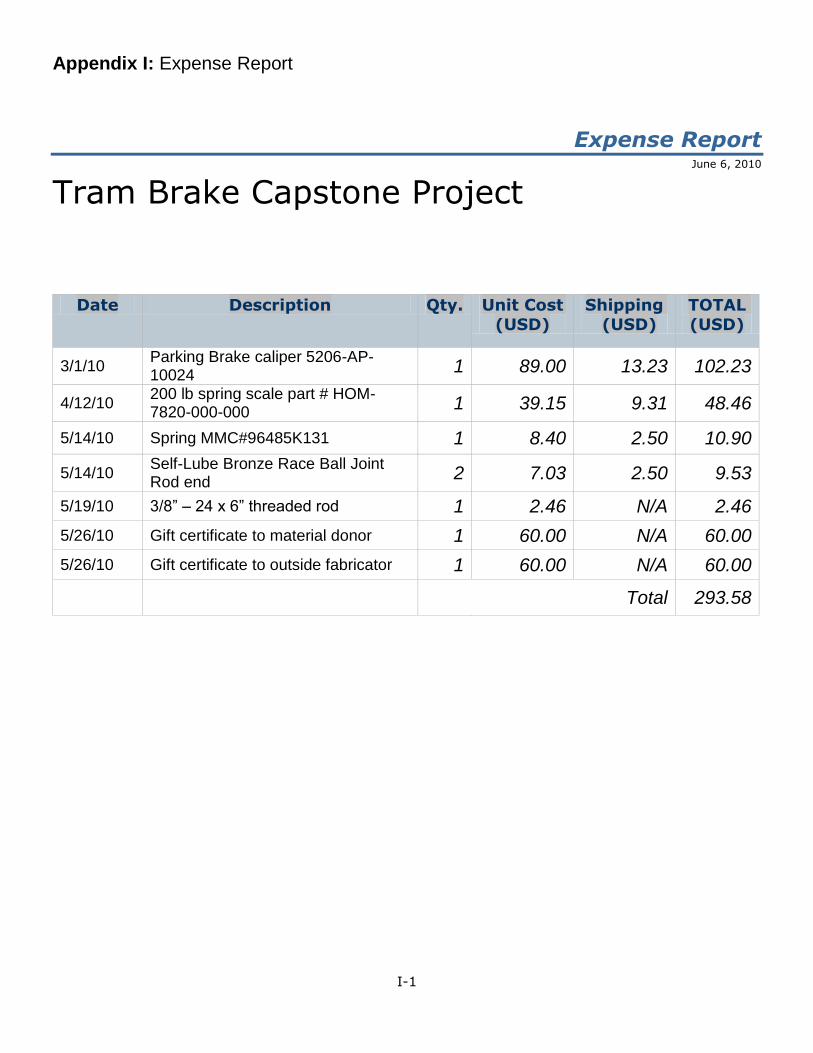
I-1
Appendix I: Expense Report
Expense Report June 6, 2010
Tram Brake Capstone Project
Date Description Qty. Unit Cost
(USD)
Shipping
(USD)
TOTAL
(USD)
3/1/10 Parking Brake caliper 5206-AP-10024
1 89.00 13.23 102.23
4/12/10 200 lb spring scale part # HOM-7820-000-000
1 39.15 9.31 48.46
5/14/10 Spring MMC#96485K131 1 8.40 2.50 10.90
5/14/10 Self-Lube Bronze Race Ball Joint Rod end
2 7.03 2.50 9.53
5/19/10 3/8” – 24 x 6” threaded rod 1 2.46 N/A 2.46
5/26/10 Gift certificate to material donor 1 60.00 N/A 60.00
5/26/10 Gift certificate to outside fabricator 1 60.00 N/A 60.00
Total 293.58
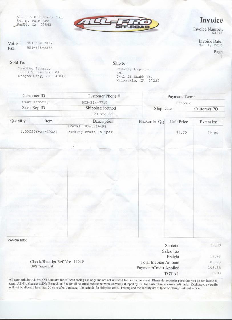
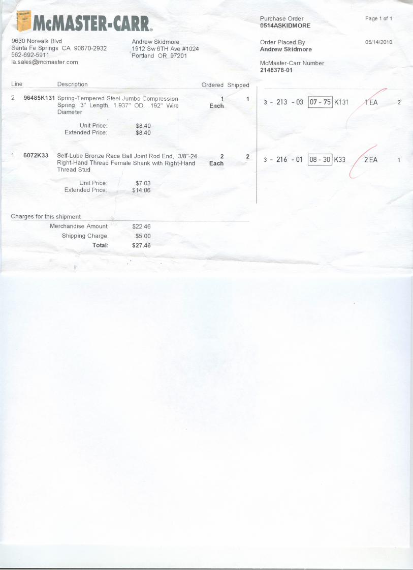
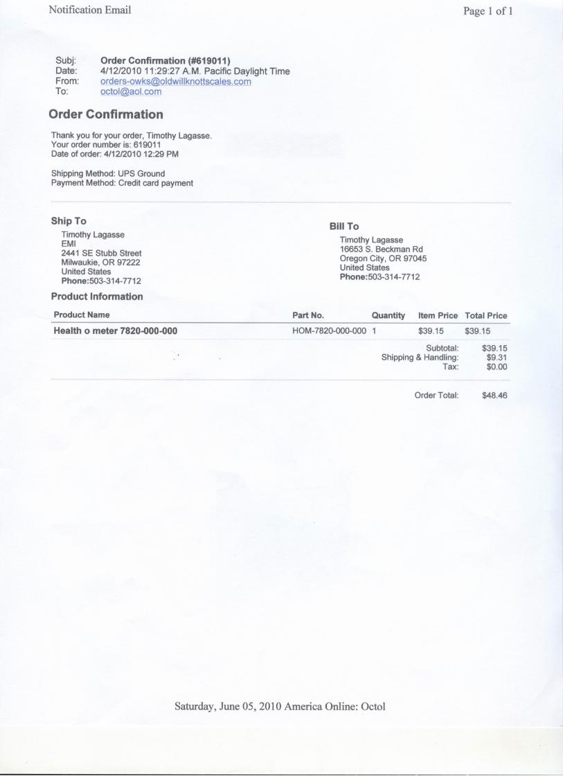
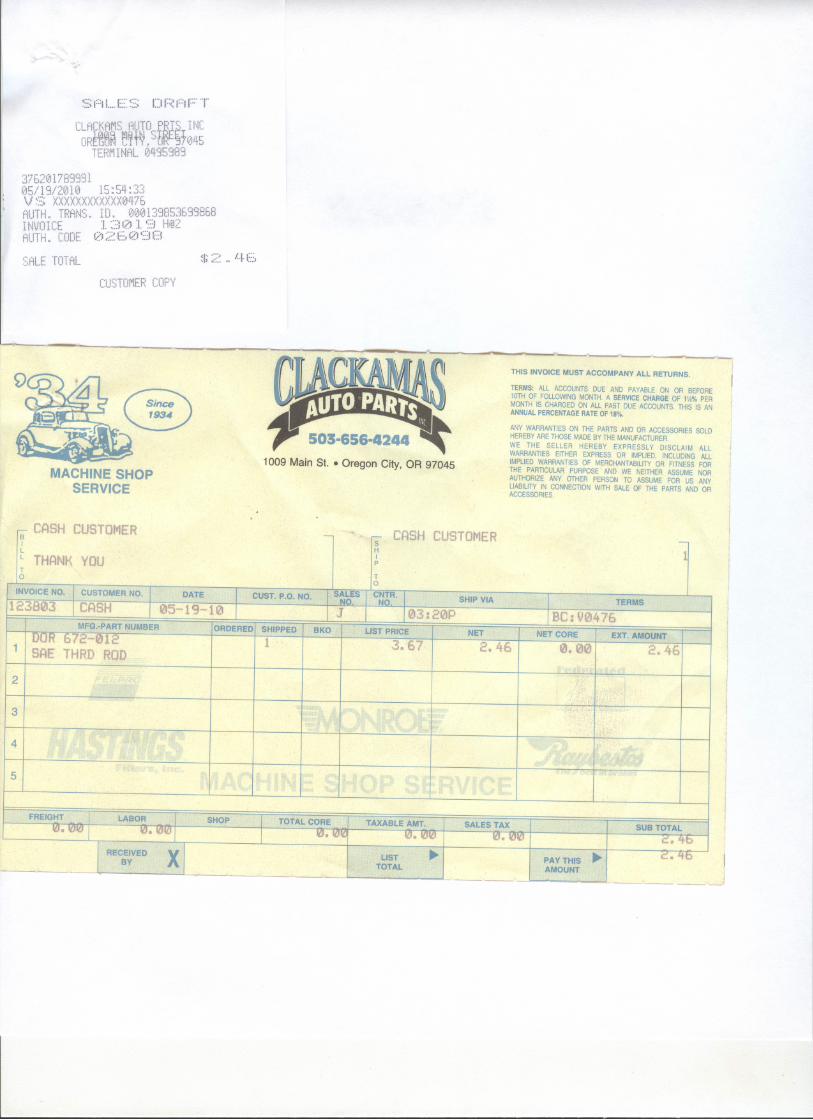

J-1
Appendix J: Approval & Project Handover Letter
Customer:
Zdenek Zumr
1024 SW Troy St.
Portland, OR 97219
503 515 3351
The Trambreak team:
Tim Lagasse
Andrew Skidmore
Binh Nguyen
Project Advisor:
Dr. Yi
Portland, June 6 2010
Trambreak Project Handover
As the customer in the 2010 Tram Brake Capstone Project by above team, I would like to
express my gratitude for the professional execution of the project. All design specifications have
been met and the relevant safety features successfully tested in my presence.
The project was executed on schedule with final delivery on 06/02/2010.
At this time here on out I assume responsibility for all aspects of operation of the equipment
including but not limited to, installation, maintenance, calibration and verification of operation as
needed.
The Trambreak team, Dr. Yi, and PSU are free of liability in any form in connection with this
project.
Sincerely
Zdenek Zumr
Signed
Portland, OR
June 6 2010

K-1
Appendix K: Production Drawings Drawings for all components made by the design team are in this appendix. The page numbers are specified by the appropriate drawing number, and the drawings are in numerical order.
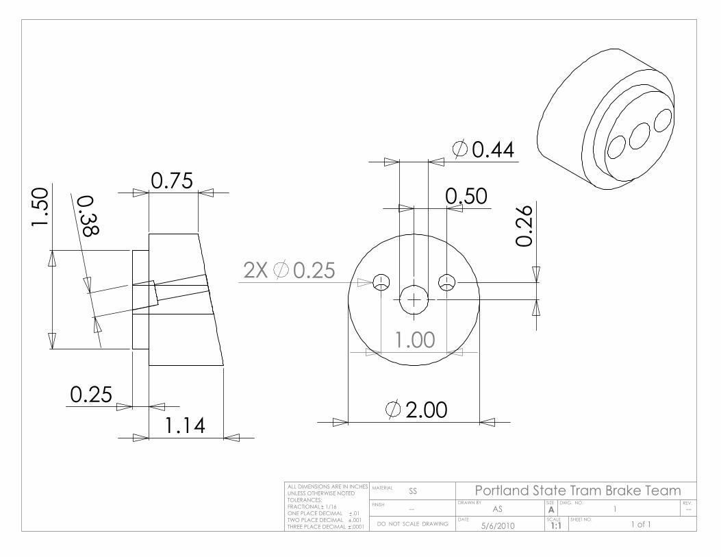
1.14
0.75
1.50
0.25
0.38
2.00
0.44
2X 0.25
1.00
0.26
0.50
Portland State Tram Brake TeamSIZE DWG. NO.
AREV.
MATERIAL
FINISH
SS
--
DO NOT SCALE DRAWING
ALL DIMENSIONS ARE IN INCHESUNLESS OTHERWISE NOTEDTOLERANCES:FRACTIONAL 1/16ONE PLACE DECIMAL .01TWO PLACE DECIMAL .001THREE PLACE DECIMAL .0001
SCALE SHEET NO.1:1
DATE
DRAWN BYAS
5/6/2010 1 of 1
1 --
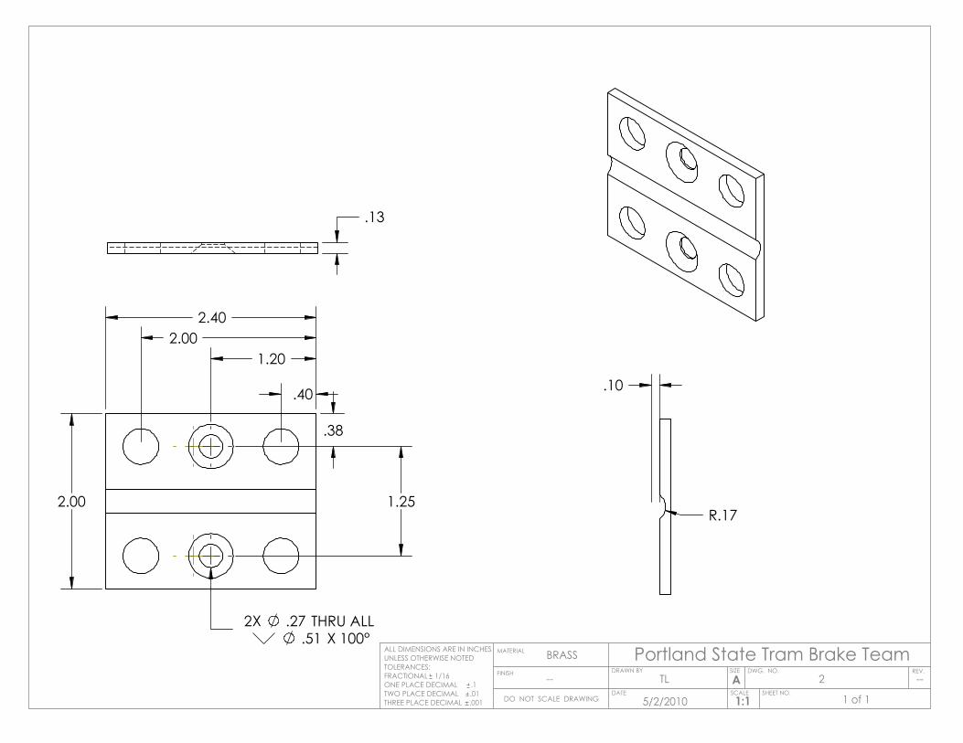
2.00
2.40
.51 X 100°2X .27 THRU ALL
1.20
.38
1.25
.40
2.00
.13
.10
R.17
Portland State Tram Brake TeamSIZE DWG. NO.
AREV.
MATERIAL
FINISH
BRASS
--
DO NOT SCALE DRAWING
ALL DIMENSIONS ARE IN INCHESUNLESS OTHERWISE NOTEDTOLERANCES:FRACTIONAL 1/16ONE PLACE DECIMAL .1TWO PLACE DECIMAL .01THREE PLACE DECIMAL .001
SCALE SHEET NO.1:1
DATE
DRAWN BYTL
5/2/2010 1 of 1
2 --
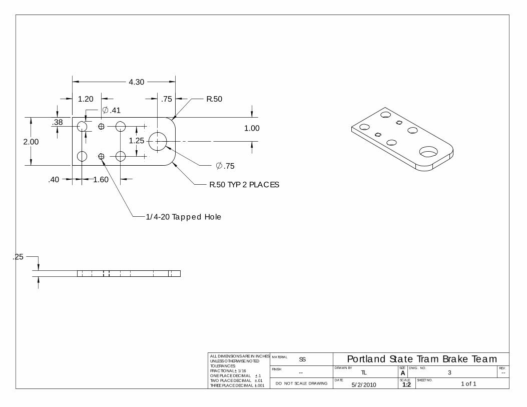
1.00
3
Portland State Tram Brake TeamSIZE DWG. NO.
AREV.
MATERIAL
FINISH
SS
--
DO NOT SCALE DRAWING 1 of 15/2/2010
TLSCALE
DRAWN BY
DATE.001 1:2
SHEET NO.
ALL DIMENSIONS ARE IN INCHESUNLESS OTHERWISE NOTEDTOLERANCES:FRACTIONAL 1/16ONE PLACE DECIMAL .1TWO PLACE DECIMAL .01THREE PLACE DECIMAL
--
.25
1/4-20 Tapped Hole
1.20
2.00
4.30
.75
.75
1.25
1.60 TYP 2 PLACES.50R
.50R
.40
.38.41
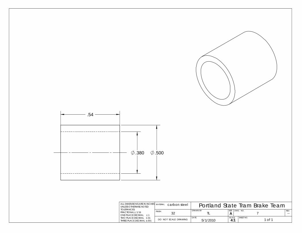
.380 .500
.54
7
Portland State Tram Brake TeamSIZE DWG. NO.
AREV.
MATERIAL
FINISH
carbon steel
32
DO NOT SCALE DRAWING 1 of 15/1/2010
TLSCALE
DRAWN BY
DATE.001 4:1
SHEET NO.
ALL DIMENSIONS ARE IN INCHESUNLESS OTHERWISE NOTEDTOLERANCES:FRACTIONAL 1/16ONE PLACE DECIMAL .1TWO PLACE DECIMAL .01THREE PLACE DECIMAL
--
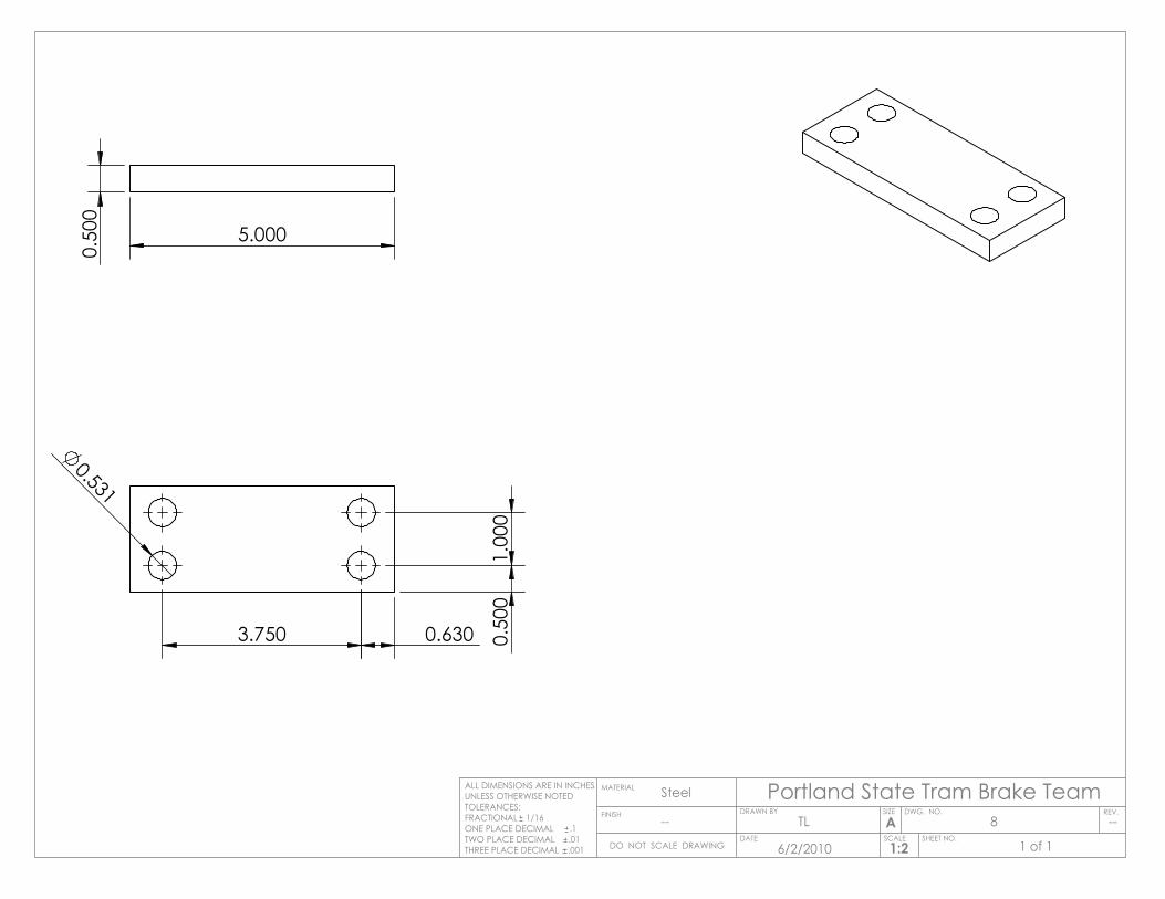
5.000
0.50
0
0.531
0.630 0.50
01.
000
3.750
Portland State Tram Brake TeamSIZE DWG. NO.
AREV.
MATERIAL
FINISH
Steel
--
DO NOT SCALE DRAWING
ALL DIMENSIONS ARE IN INCHESUNLESS OTHERWISE NOTEDTOLERANCES:FRACTIONAL 1/16ONE PLACE DECIMAL .1TWO PLACE DECIMAL .01THREE PLACE DECIMAL .001
SCALE SHEET NO.1:2
DATE
DRAWN BYTL
6/2/2010 1 of 1
8 --
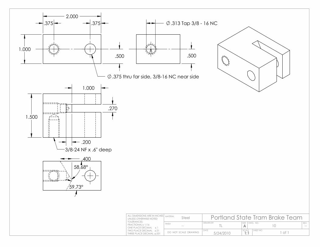
1.000
2.000
.375 thru far side, 3/8-16 NC near side
.375.375
.500
.270
1.000
.200
.400
1.500
3/8-24 NF x .6" deep
.313 Tap 3/8 - 16 NC
.500
58.68°
59.73°
Portland State Tram Brake TeamSIZE DWG. NO.
AREV.
MATERIAL
FINISH
Steel
--
DO NOT SCALE DRAWING
ALL DIMENSIONS ARE IN INCHESUNLESS OTHERWISE NOTEDTOLERANCES:FRACTIONAL 1/16ONE PLACE DECIMAL .1TWO PLACE DECIMAL .01THREE PLACE DECIMAL .001
SCALE SHEET NO.1:1
DATE
DRAWN BYTL
5/24/2010 1 of 1
10 --

.88
R.50
4.00
11.00
.25
.25.38
1.49
1.38
.57
Portland State Tram Brake TeamSIZE DWG. NO.
AREV.
MATERIAL
FINISH
Steel
--
DO NOT SCALE DRAWING
ALL DIMENSIONS ARE IN INCHESUNLESS OTHERWISE NOTEDTOLERANCES:FRACTIONAL 1/16ONE PLACE DECIMAL .1TWO PLACE DECIMAL .01THREE PLACE DECIMAL .001
SCALE SHEET NO.1:4
DATE
DRAWN BYTL
5/1/2010 1 of 1
11 --
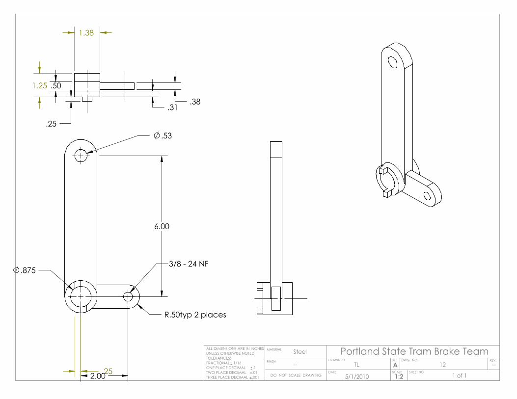
.875
.25
.53
6.00
R.50typ 2 places
2.00
3/8 - 24 NF
1.38
1.25
.38
.25
.31
.50
Portland State Tram Brake TeamSIZE DWG. NO.
AREV.
MATERIAL
FINISH
Steel
--
DO NOT SCALE DRAWING
ALL DIMENSIONS ARE IN INCHESUNLESS OTHERWISE NOTEDTOLERANCES:FRACTIONAL 1/16ONE PLACE DECIMAL .1TWO PLACE DECIMAL .01THREE PLACE DECIMAL .001
SCALE SHEET NO.1:2
DATE
DRAWN BYTL
5/1/2010 1 of 1
12 --
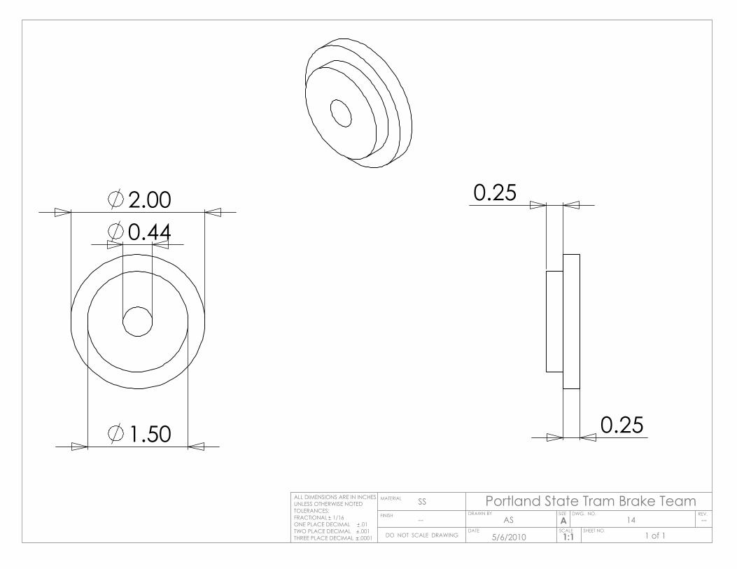
2.00
1.50
0.44
0.25
0.25
Portland State Tram Brake TeamSIZE DWG. NO.
AREV.
MATERIAL
FINISH
SS
--
DO NOT SCALE DRAWING
ALL DIMENSIONS ARE IN INCHESUNLESS OTHERWISE NOTEDTOLERANCES:FRACTIONAL 1/16ONE PLACE DECIMAL .01TWO PLACE DECIMAL .001THREE PLACE DECIMAL .0001
SCALE SHEET NO.1:1
DATE
DRAWN BYAS
5/6/2010 1 of 1
14 --
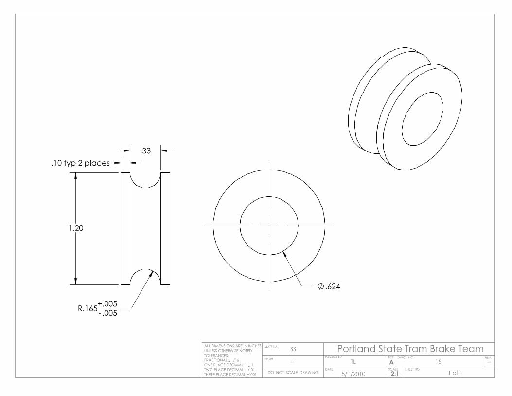
.33.10 typ 2 places
1.20
R.165- .005+.005
.624
Portland State Tram Brake TeamSIZE DWG. NO.
AREV.
MATERIAL
FINISH
SS
--
DO NOT SCALE DRAWING
ALL DIMENSIONS ARE IN INCHESUNLESS OTHERWISE NOTEDTOLERANCES:FRACTIONAL 1/16ONE PLACE DECIMAL .1TWO PLACE DECIMAL .01THREE PLACE DECIMAL .001
SCALE SHEET NO.2:1
DATE
DRAWN BYTL
5/1/2010 1 of 1
15 --
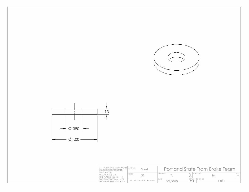
1.00
.380
.13
Portland State Tram Brake TeamSIZE DWG. NO.
AREV.
MATERIAL
FINISH
Steel
32
DO NOT SCALE DRAWING
ALL DIMENSIONS ARE IN INCHESUNLESS OTHERWISE NOTEDTOLERANCES:FRACTIONAL 1/16ONE PLACE DECIMAL .1TWO PLACE DECIMAL .01THREE PLACE DECIMAL .001
SCALE SHEET NO.2:1
DATE
DRAWN BYTL
5/1/2010 1 of 1
16 --
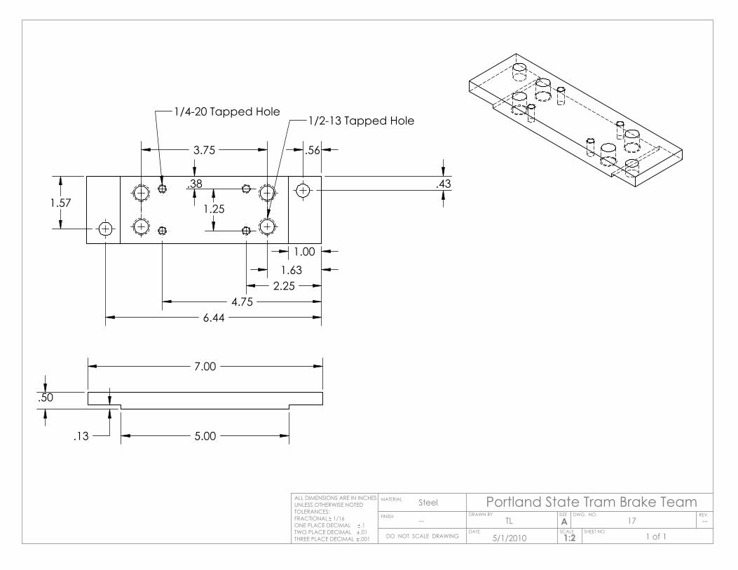
5.00
7.00
.50
.13
3.75
.43
.56
6.44
1.57
2.254.75
1.25
1.001.63
.38
1/2-13 Tapped Hole1/4-20 Tapped Hole
Portland State Tram Brake TeamSIZE DWG. NO.
AREV.
MATERIAL
FINISH
Steel
--
DO NOT SCALE DRAWING
ALL DIMENSIONS ARE IN INCHESUNLESS OTHERWISE NOTEDTOLERANCES:FRACTIONAL 1/16ONE PLACE DECIMAL .1TWO PLACE DECIMAL .01THREE PLACE DECIMAL .001
SCALE SHEET NO.1:2
DATE
DRAWN BYTL
5/1/2010 1 of 1
17 --
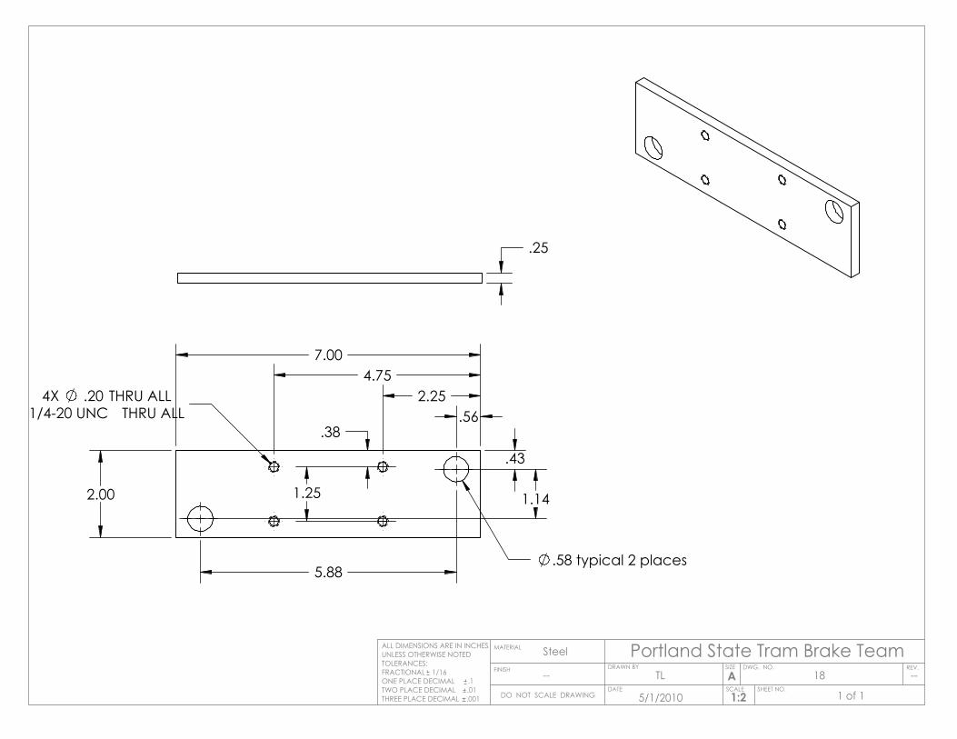
7.00
2.00
.58 typical 2 places
.43
.56
5.88
1.14
1/4-20 UNC THRU ALL4X .20 THRU ALL 2.25
4.75
.38
1.25
.25
Portland State Tram Brake TeamSIZE DWG. NO.
AREV.
MATERIAL
FINISH
Steel
--
DO NOT SCALE DRAWING
ALL DIMENSIONS ARE IN INCHESUNLESS OTHERWISE NOTEDTOLERANCES:FRACTIONAL 1/16ONE PLACE DECIMAL .1TWO PLACE DECIMAL .01THREE PLACE DECIMAL .001
SCALE SHEET NO.1:2
DATE
DRAWN BYTL
5/1/2010 1 of 1
18 --
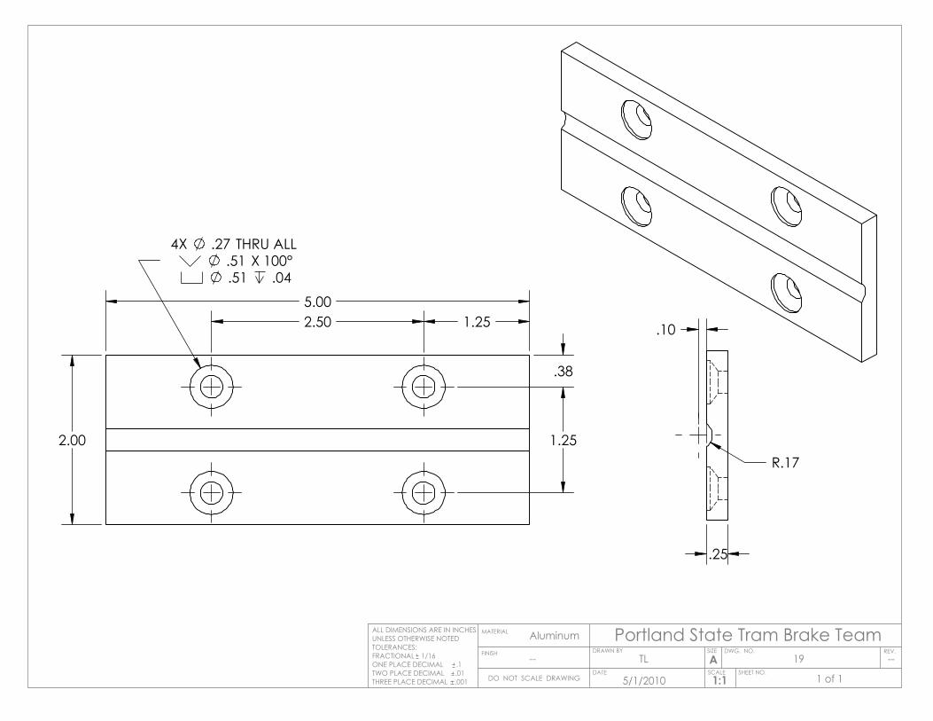
2.00
5.00
.51 .04 .51 X 100°
4X .27 THRU ALL
1.25
.38
1.25
2.50
.25
.10
R.17
Portland State Tram Brake TeamSIZE DWG. NO.
AREV.
MATERIAL
FINISH
Aluminum
--
DO NOT SCALE DRAWING
ALL DIMENSIONS ARE IN INCHESUNLESS OTHERWISE NOTEDTOLERANCES:FRACTIONAL 1/16ONE PLACE DECIMAL .1TWO PLACE DECIMAL .01THREE PLACE DECIMAL .001
SCALE SHEET NO.1:1
DATE
DRAWN BYTL
5/1/2010 1 of 1
19 --
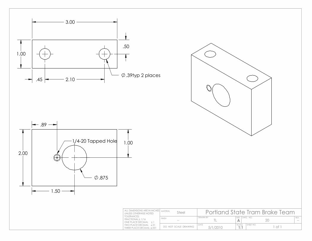
.875
1.50
.89
1.00
2.00
1/4-20 Tapped Hole
1.00
3.00
.39typ 2 places.45 2.10
.50
Portland State Tram Brake TeamSIZE DWG. NO.
AREV.
MATERIAL
FINISH
Steel
--
DO NOT SCALE DRAWING
ALL DIMENSIONS ARE IN INCHESUNLESS OTHERWISE NOTEDTOLERANCES:FRACTIONAL 1/16ONE PLACE DECIMAL .1TWO PLACE DECIMAL .01THREE PLACE DECIMAL .001
SCALE SHEET NO.1:1
DATE
DRAWN BYTL
5/1/2010 1 of 1
20 --
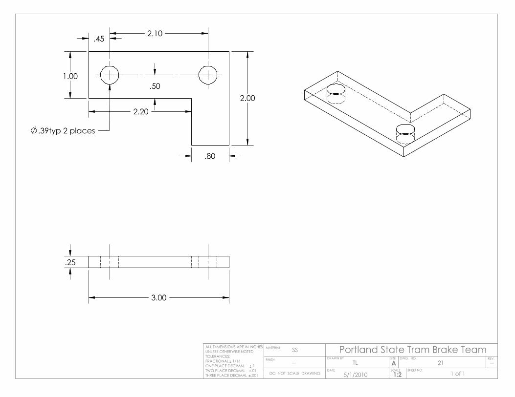
3.00
.25
.39typ 2 places
.45 2.10
1.00
2.20
.80
2.00.50
Portland State Tram Brake TeamSIZE DWG. NO.
AREV.
MATERIAL
FINISH
SS
--
DO NOT SCALE DRAWING
ALL DIMENSIONS ARE IN INCHESUNLESS OTHERWISE NOTEDTOLERANCES:FRACTIONAL 1/16ONE PLACE DECIMAL .1TWO PLACE DECIMAL .01THREE PLACE DECIMAL .001
SCALE SHEET NO.1:2
DATE
DRAWN BYTL
5/1/2010 1 of 1
21 --
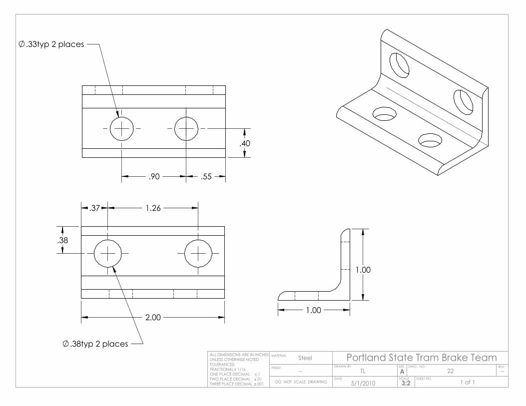
2.00
.38typ 2 places
.37 1.26
.38
.33typ 2 places
.90
.40
.55
1.00
1.00
Portland State Tram Brake TeamSIZE DWG. NO.
AREV.
MATERIAL
FINISH
Steel
--
DO NOT SCALE DRAWING
ALL DIMENSIONS ARE IN INCHESUNLESS OTHERWISE NOTEDTOLERANCES:FRACTIONAL 1/16ONE PLACE DECIMAL .1TWO PLACE DECIMAL .01THREE PLACE DECIMAL .001
SCALE SHEET NO.3:2
DATE
DRAWN BYTL
5/1/2010 1 of 1
22 --
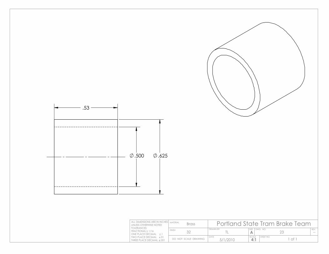
.500 .625
.53
Portland State Tram Brake TeamSIZE DWG. NO.
AREV.
MATERIAL
FINISH
Brass
32
DO NOT SCALE DRAWING
ALL DIMENSIONS ARE IN INCHESUNLESS OTHERWISE NOTEDTOLERANCES:FRACTIONAL 1/16ONE PLACE DECIMAL .1TWO PLACE DECIMAL .01THREE PLACE DECIMAL .001
SCALE SHEET NO.4:1
DATE
DRAWN BYTL
5/1/2010 1 of 1
23 --
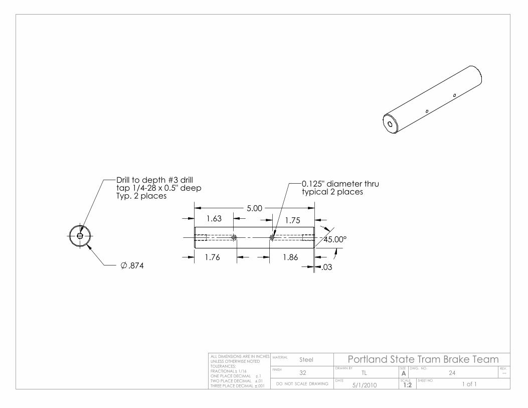
.874
Drill to depth #3 drilltap 1/4-28 x 0.5" deepTyp. 2 places
5.00
.03
45.00°
1.76 1.86
1.63 1.75
0.125" diameter thrutypical 2 places
Portland State Tram Brake TeamSIZE DWG. NO.
AREV.
MATERIAL
FINISH
Steel
32
DO NOT SCALE DRAWING
ALL DIMENSIONS ARE IN INCHESUNLESS OTHERWISE NOTEDTOLERANCES:FRACTIONAL 1/16ONE PLACE DECIMAL .1TWO PLACE DECIMAL .01THREE PLACE DECIMAL .001
SCALE SHEET NO.1:2
DATE
DRAWN BYTL
5/1/2010 1 of 1
24 --