Embed Size (px)
Citation preview
Clays' and Clay Minerals', Vol. 48 , No. I, 111 - 119, 2000 .
TRANSMISSION ELECTRON MICROSCOPY OF SYNTHETIC 2- A N D 6- LINE FERRIHYDRITE
DAWN E. JANNEY, I JOHN M. COWLEY, 2 AND PETER R. BUSECK a
1Departments of Geology and Chemistry/Biochemistry and ;Department of Physics and Astronomy, Arizona State University, Tempe, Arizona 85287, USA
Abstraet~High-resolution transmission electron microscopy (HRTEM), selected-area electron diffraction (SAED), annular dark-field scanning transmission electron microscope (STEM) images, and electron nano- diffraction were used to examine structures of synthetic 2- and 6-line ferrihydrite specimens. HRTEM images of 2-line ferrihydrite (2LFh) show scattered small (-- 1-3 nm) areas with lattice fringes surrounded by areas free of fringes. All SAED patterns show two bright rings corresponding to d-values of -0.15 and 0.25 nm; each ring has a conspicuous shoulder on each side. Faint rings corresponding to d-values of 0.08, 0.095, 0.100, 0.106-0.114 (very broad ring), and 0.122 nm are visible in strongly exposed SAED patterns. Nanodiffraction patterns show conspicuous streaks and a lack of superlattice formation.
HRTEM images of 6-line ferrihydrite (6LFh) display larger crystallites (typically - 5 - 6 nm) with lattice fringes visible in many thin areas. SAED patterns show rings corresponding to d-values of 0.148, 0.156, 0.176, 0.202, 0.227, and 0.25-0.26 nm and a shoulder extending between d-values of -0.25 and 0.32 nm. Faint rings corresponding to d-values of 0.086, 0.093, 0.107, 0.112, 0.119, 0.125, and 0.135 nm are visible in strongly exposed SAED patterns. Small quantities of hematite, magnetite or maghemite, and an acicular material tentatively identified as goethite were observed in the 6-line ferrihydrite, but these quantities do not contribute significantly to the overall diffracted intensity from the sample.
Key Words--Ferrihydrite, High-Resolution Transmission Electron Microscopy (HRTEM), Nanodiffrac- tion, Selected-Area Electron Diffraction (SAED).
INTRODUCTION
Fefrihydrite is a common iron oxide mineral in low- temperature surface environments such as soils, lake- bottom sediments, drainage ditches, and hot- and cold- spring deposits (e.g., Chukhrov e t al., 1973; Schwert- mann and Fischer, 1973; Childs e t al., 1986; Schwert- mann et al,, 1987; Schwertmann, 1988; Schwertmann and Taylor, 1989). Because of its small grain size (<--6 nm) and large surface area (hundreds of square meters per gram), even small amounts of ferrihydrite can have important consequences for many soil properties (Cor- nell and Schwertmann, 1996; Jambor and Dutrizac, 1998; Childs, 1992). Ferrihydrite also occurs as an aqueous alteration product in meteorites (Li e t al.,
1999; Brearley, 1997; Lee et al., 1996), and it is an important corrosion product of iron and steel. Natu- rally occurring ferrihydrite can be formed by biologi- cal processes (e.g., Chukhrov e t al., 1973; Schwert- mann and Fischer, 1973; Konhauser, 1997).
Ferrihydrite is important in environmental geology because of its common occurrence in mine-waste en- vironments and its demonstrated ability to adsorb or form coprecipitates with organic compounds and ions of a wide variety of elements (Jambor and Dutrizac, 1998; Alpers et al., 1994; Bigham, 1994; Jambor, 1994). Natural ferrihydrite is difficult to isolate and characteristically contains impurities, even a few mole percent of which may have significant effects on its structure and phase-transition behavior (Parfitt, 1992; Paige et al., 1997; Cornell and Schwertmann, 1996).
Copyright �9 2000, The Clay Minerals Society 11
Thus, most investigations of the chemical and crystal- lographic characteristics of ferrihydrite use synthetic samples comparable to those in this study.
The number of peaks in X-ray diffraction (XRD) patterns of ferrihydrite is variable. It is common to designate ferrihydrite samples by the number of peaks corresponding to d-values from -0 .15 to --0.25 nm, for example "2-line ferrihydrite (2LFh)," and "6-l ine ferrihydrite (6LFh)." We follow this convention; how- ever, only synthetic 6LFh samples are strictly consis- tent with the International Mineralogical Association definition (Fleischer e t al., 1975; Farmer, 1992). Other commonly used names for ferrihydrite include "pro- toferrihydrite" (the name originally proposed for 2LFh), "amorphous ferric oxide," and "hydrous ferric oxide" (e.g., Chukhrov et al., 1973; Towe and Brad- ley, 1976; Farmer, 1992; Manceau et al., 1995).
Although both natural and synthetic ferrihydrite oc- cur in forms with intermediate numbers of peaks (Carlson and Schwertmann, 1981; Childs et aL, 1986; Brearley, 1997; Lee e t al., 1996; Lewis and Cardile, 1989; Li et al., 1999; Schwertmann e t al., 1999), only synthetic 2LFh and 6LFh have been widely used for structural and chemical studies. Under appropriate conditions, ferrihydrite can transform to hematite, goe- thite, lepidocrocite, magnetite, or maghemite (Cornell and Schwertmann, 1996; Campbell et al., 1997). To our knowledge, transformations among the forms of ferrihydrite with varying numbers of peaks have not been demonstrated.

112 Janney, Cowley, and Buseck Clays and Clay Minerals
p .
f -
r o
1
3 4 5
i i i i i
10 30 50 70 90 110 2 theta (degrees)
Figure 1. XRD patterns of ferrihydrite: 6LFh (top) and 2LFh (bottom) (CrKtx radiation). Numbers above the pattern of 6LFh indicate peaks used in identification.
Despite an early suggestion that 36% of the iron in 6LFh is in tetrahedral coordination (Eggleton and Fitz- patrick, 1988), synchrotron techniques have shown that essentially all of the iron in the interiors of 6LFh crystals is octahedrally coordinated (e.g., Combes et al., 1989, 1990; Manceau and Drits, 1993; Zhao et al., 1993; Shinoda et al., 1994; Waychunas et al., 1996). Intermediate-range structures involving possible cor- ner-, edge-, and face-sharing between octahedra re- main subjects of active investigation (Combes et al., 1989, 1990; Waychunas et al., 1993, 1996; Manceau and Drits, 1993; Shinoda e t al., 1994) as do coordi- nation environments of iron atoms at crystal surfaces (Zhao e t al., 1994; Manceau and Gates, 1997). Longer- range structures (on a scale of a few nm) and the re- suiting numbers of peaks in XRD patterns were in- vestigated using simulated X-ray diffraction (Drits et al., 1993), leading to the suggestions that ferrihydrite is a mixture containing 25% normal hematite and that the main structural difference between 2LFh and 6LFh may be the size of the coherently diffracting domains (Drits et aL, 1993; Manceau and Drits, 1993). How- ever, direct observations to test these suggestions are lacking.
We used high-resolution transmission electron mi- croscopy (HRTEM), selected-area electron diffraction (SAED), dark-field scanning transmission electron mi- croscope (STEM) images, and electron nanodiffraction to study samples of synthetic 2LFh and 6LFh. Our research has two goals: 1) to use direct observations to explore structural similarities and differences be- tween the samples and 2) to provide HRTEM and elec- tron diffraction data on characteristics of synthetic 2LFh and 6LFh because of their importance for chem- ical and environmental studies.
SAMPLES AND METHODS
Samples of 2LFh and 6LFh were synthesized at the Lehrstuhl ftir Bodenkunde, Technische Universit/it
MiJnchen, using methods from Schwertmann and Cor- nell (1991). The 2LFh was synthesized by adding a 1 M solution of reagent-grade potassium hydroxide to a 0.2 M solution of reagent-grade ferric nitrate with con- stant stirring until the pH reached 7-8, and repeatedly washing and centrifuging to remove remaining elec- trolytes. The 6LFh was synthesized by adding 20 g ferric nitrate to 2 L of distilled water that had been preheated to 75~ holding the solution at 75~ for 10- 12 min, cooling it with ice water, and dialyzing to remove electrolytes. The resulting precipitates in both cases were freeze-dried.
Samples were prepared for powder XRD by grind- ing them gently, moistening them with propanol, spreading them on a zero-background quartz plate, and allowing them to air-dry. XRD patterns (Figure 1) were measured by summing ten scans using CrKc~ ra- diation from a Rigaku RU200B diffractometer with a rotating-anode source and a diffracted-beam curved- graphite monochromator. Each scan used a 0.05 ~ step size and a counting time of 0.5 s per step for 6LFh or 1.0 s per step for 2LFh, which diffracted less strongly. The resulting XRD patterns are similar to published pattems for both natural and synthetic 2LFh and 6LFh (e.g., Eggleton and Fitzpatrick, 1988; Schwertmann and Cornell, 1991; Cornell and Schwertmann, 1996; Drits e t aL, 1993).
TEM samples were prepared by ultrasonicating a small amount of ferrihydrite powder in a few drops of high-purity water for 2-3 h, then placing a droplet of the faintly colored water on a holey-carbon or holey- silicon-monoxide film supported by a copper-mesh TEM grid. A cold-water bath was used during ultra- sonication to inhibit the possible formation of more crystalline iron minerals. Ultrasonication did not com- pletely separate individual crystals but produced ag- gregates with electron-transparent edges.
HRTEM images were obtained using a JEOL 4000EX microscope operating at 400 kV (point-to- point resolution 0.17 nm) and a Topcon 002B micro- scope operating at 200 kV (point-to-point resolution 0.18 nm). Samples with silicon monoxide substrates were less useful because of electron-beam-induced charging. The best images were obtained from thin edges of ferrihydrite aggregates that were supported by the holey-carbon substrate at several points.
SAED patterns were obtained using the smallest se- lected-area aperture available on each microscope and a camera length that produced a difference of --7 mm in radii of rings diffracted from d-values of 0.15 and 0.25 nm. At least two films were taken of each dif- fraction pattern: one or more using relatively short ex- posures (typically --<45 s) to show diffraction from d- values larger than --0.25 nm and one long exposure (typically 90-180 s) to emphasize d-values smaller than -0 .35 nm. Rings representing d-values <0.15 nm
Vol. 48, No. 1, 2000 TEM study of synthetic 2- and 6-line ferrihydrite 113
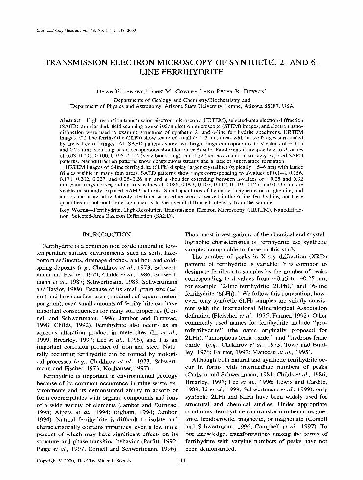
Figure 2. HRTEM image of 2LFh showing single crystallites and material without lattice fringes at edge of aggregate. Note small groups of lattice fringes (examples at arrows), and straight edges of crystallites along thin edges.
were always faint, and could only be measured on the most strongly exposed negatives.
Nanodiffraction patterns (Cowley, 1998) were ob- tained with a Vacuum Generators HB-5 Scanning Transmission Electron Microscope (STEM) using a beam diameter of --0.7 nm. Because of the small beam convergence angle and the small thickness of the crys- tallites, these patterns do not show the same detail in- side individual spots as obtained in conventional con- vergent-beam electron diffraction patterns. Instead, spots in nanodiffraction patterns are interpreted as though they were enlarged reflections in SAED pat- terns. Despite the small sizes of the crystallites and their tendency to be superposed on each other, zone- axis nanodiffraction patterns in which only one crys- tallite was strongly diffracting could be obtained. An- nular-dark-field STEM images (Cowley, 1998), which
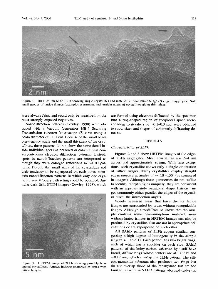
Figure 3. HRTEM image of 2LFh showing possibly hex- agonal crystallites. Arrows indicate examples of areas with lattice fringes.
are formed using electrons diffracted by the specimen into a ring-shaped region of reciprocal space corre- sponding to d-values of --0.1~0.3 nm, were obtained to show sizes and shapes of coherently diffracting do- mains.
RESULTS
Characteristics of 2LFh
Figures 2 and 3 show HRTEM images of the edges of 2LFh aggregates. Most crystallites are 2 - 4 nm across and approximately equant. With rare excep- tions, each crystallite shows only a single orientation of lattice fringes. Many crystallites display straight edges meeting at angles of --110~ ~ (as measured in images). Although these geometries do not suffice to identify morphologies uniquely, they are consistent with an approximately hexagonal shape. Lattice frin- ges commonly either parallel the edges of the crystals or bisect the intersection angles.
Widely scattered areas that have distinct lattice fringes are surrounded by areas without recognizable fringes. Although nanodiffraction shows that the sam- ple contains some near-amorphous material, areas without lattice fringes in HRTEM images can also be produced by crystallites that are not in appropriate ori- entations or are superposed on each other.
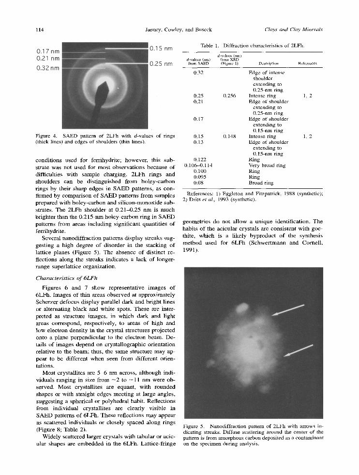
All SAED patterns of 2LFh appear similar, sug- gesting a high degree of homogeneity in the sample (Figure 4; Table 1). Each pattern has two bright rings, each of which has a shoulder on each side. SAED patterns of the holey-carbon substrate by itself have broad, diffuse tings whose centers are at --0.215 and - 0 . 1 2 nm, which overlap the 2LFh pattern. The sili- con-monoxide substrate also produces two tings that do not overlap those of the ferrihydrite but are too faint to measure in SAED patterns obtained under the
114 Janney, Cowley, and Buseck Clays and Clay Minerals
Figure 4. SAED pattern of 2LFh with d-values of rings (thick lines) and edges of shoulders (thin lines).
condit ions used for ferrihydrite; however, this sub- strate was not used for most observat ions because of difficulties with sample charging. 2LFh rings and shoulders can be dist inguished f rom holey-carbon rings by their sharp edges in S A E D patterns, as con- firmed by comparison of S A E D patterns f rom samples prepared with holey-carbon and s i l icon-monoxide sub- strates. The 2LFh shoulder at 0 .21-0.25 nm is much brighter than the 0 .215-nm holey-carbon ring in S A E D patterns f rom areas including significant quantit ies of ferrihydrite.
Several nanodiffract ion patterns display streaks sug- gesting a high degree of disorder in the stacking of lattice planes (Figure 5). The absence of distinct re- flections along the streaks indicates a lack of longer- range superlattice organization.
Characteristics o f 6LFh
Figures 6 and 7 show representative images o f 6LFh. Images o f thin areas observed at approximately Scherzer defocus display parallel dark and bright lines or alternating black and white spots, These are inter- preted as structure images, in which dark and light areas correspond, respectively, to areas of high and low electron density in the crystal structures projected onto a plane perpendicular to the electron beam. De- tails of images depend on crystal lographic orientation relative to the beam; thus, the same structure may ap- pear to be different when seen f rom different orien- tations.
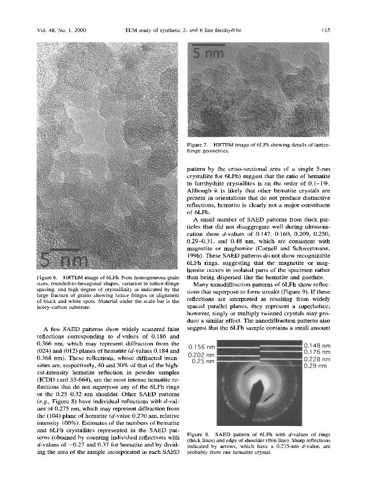
Most crystall i tes are 5 - 6 nm across, al though indi- viduals ranging in size f rom - 2 to - 1 1 nm were ob- served. Mos t crystall i tes are equant, with rounded shapes or with straight edges meet ing at large angles, suggesting a spherical or polyhedral habit. Reflections f rom individual crystall i tes are clearly visible in S A E D patterns of 6LFh. These reflections may appear as scattered individuals or closely spaced along rings (Figure 8; Table 2).
Widely scattered larger crystals with tabular or acic- ular shapes are embedded in the 6LFh. Lat t ice-fr inge
Table 1. Diffraction characteristics of 2LFh.
d-values (nm) d-values (nm) from XRD from SAED (Figure 1) Description References
0.32 Edge of intense shoulder extending to 0.25-nm ring
0.25 0.256 Intense ring 1, 2 0.21 Edge of shoulder
extending to 0.25-rim ring
0.17 Edge of shoulder extending to 0.15-nm ring
0.15 0.148 Intense ring 1, 2 0.13 Edge of shoulder
extending to 0.15-nm ring
0.122 Ring 0.106-0.114 Very broad ring
0.100 Ring 0.095 Ring 0.08 Broad ring
References: 1) Eggleton and Fitzpatrick, 1988 (synthetic); 2) Drits et al., 1993 (synthetic).
geometr ies do not al low a unique identification. The habits of the acicular crystals are consistent with goe- thite, which is a l ikely byproduct of the synthesis method used for 6LFh (Schwer tmann and Cornell , 1991).
Figure 5. Nanodiffraction pattern of 2LFh with arrows in- dicating streaks. Diffuse scattering around the center of the pattern is from amorphous carbon deposited as a contaminant on the specimen during analysis.
Vol. 48, No. 1, 2000 TEM study of synthetic 2- and 6-line ferrihydrite 115
Figure 7. HRTEM image of 6LFh showing details of lattice- fringe geometries.
Figure 6. HRTEM image of 6LFh. Note homogeneous grain sizes, rounded-to-hexagonal shapes, variation in lattice-fringe spacing, and high degree of crystallinity as indicated by the large fraction of grains showing lattice fringes or alignment of black and white spots. Material under the scale bar is the holey-carbon substrate.
A few SAED patterns show widely scattered faint reflections corresponding to d-values of 0.186 and 0.366 nm, which may represent diffraction from the (024) and (012) planes of hematite (d-values 0.184 and 0.368 nm). These reflections, whose diffracted inten- sities are, respectively, 40 and 30% of that of the high- est-intensity hematite reflection in powder samples (ICDD card 33-664), are the most intense hematite re- flections that do not superpose any of the 6LFh rings or the 0.25-0.32 nm shoulder. Other SAED patterns (e.g., Figure 8) have individual reflections with d-val- ues of 0.275 nm, which may represent diffraction from the (104) plane of hematite (d-value 0.270 nm, relative intensity 100%). Estimates of the numbers of hematite and 6LFh crystallites represented in the SAED pat- terns (obtained by counting individual reflections with d-values of - 0 .27 and 0.37 for hematite and by divid- ing the area of the sample incorporated in each SAED
pattern by the cross-sectional area of a single 5-nm crystallite for 6LFh) suggest that the ratio of hematite to ferrihydrite crystallites is on the order of 0.1-1%. Although it is likely that other hematite crystals are present in orientations that do not produce distinctive reflections, hematite is clearly not a major constituent of 6LFh.
A small number of SAED patterns from thick par- ticles that did not disaggregate well during ultrasoni- cation show d-values of 0.147, 0.160, 0.209, 0.250, 0.29-0.31, and 0.48 nm, which are consistent with magnetite or maghemite (Cornell and Schwertmann, 1996). These SAED patterns do not show recognizable 6LFh rings, suggesting that the magnetite or mag- hemite occurs in isolated parts of the specimen rather than being dispersed like the hematite and goethite.
Many nanodiffraction patterns of 6LFh show reflec- tions that superpose to form streaks (Figure 9). If these reflections are interpreted as resulting from widely spaced parallel planes, they represent a superlattice; however, singly or multiply twinned crystals may pro- duce a similar effect. The nanodiffraction patterns also suggest that the 6LFh sample contains a small amount
Figure 8. SAED pattern of 6LFh with d-values of rings (thick lines) and edge of shoulder (thin line). Sharp reflections indicated by arrows, which have a 0.275-nm d-value, are probably from one hematite crystal.

116 Clays and Clay Minerals Janney, Cowley, and Buseck
Table 2. Diffraction characteristics of 6LFh.
d-values (nm) d-values (nm) from XRD from SAED (Figure 1) Description References
0.456 Not observed 0.366 Rare individual reflections [hematite (012)?]
0.30-0.32 0.321 Edge of intense shoulder extending to 0.25- 1, 2, 3 nm ring
0.275 Rare individual reflections [hematite (104)?] 4 0.25-0.26 0.252 Intense ring 1, 2, 3, 4, 5, 6
0.227 0.222 Ring 1, 2, 3, 5, 6 0.202 0.196 Ring 1, 2, 3, 4, 5, 6 0.186 Rare, faint individual reflections [hematite
(024)?] 0.176 0.170 Ring 1, 2, 3, 4, 5, 6
0.145-0.158 0.147, 0.149 Broad zone containing large numbers of indi- l, 2, 3, 4, 5, 6 vidual reflections; many SAEDs contain distinct rings at 0.148 and 0.156 nm
0.135 Ring 0.125 Ring (visible in only one SAED) 0.119 Ring 0.112 Ring 0.107 Broad, relatively intense ring 0.093 Ring 0.086 Relatively intense ring
References: 1) Eggleton and Fitzpatrick, 1988 (synthetic); 2) Drits et al., 1993 (synthetic); 3) Towe and Bradley, 1976 (synthetic); 4) Childs et aL, 1986 (natural); 5) Carlson and Schwertmann, 1981 (natural); 6) Van der Giessen, 1966 (synthetic).
of nea r - amorphous mater ia l . Annu l a r dark-f ie ld images show rounded , coheren t ly d i f f rac t ing doma ins 3 - 1 0 n m across (Figure 10); in at least one case, a coher- ent ly di f f ract ing d o m a i n occupies only par t of a round- ed part ic le s imi lar to those in te rpre ted as s ingle c rys- tal l i tes in H R T E M images . Nanod i f f r ac t ion pa t te rns f rom different parts of this d o m a i n show s ignif icant
var ia t ions in the degree of s t reaking, sugges t ing dif- fe rences in the ex tent of d i sorder wi th in the domain . Fr inges in annu la r dark-f ie ld images wi th per iods o f 1, 1.6, or 2.7 n m m a y rep resen t Moi r6 f r inges f rom over l app ing crystal l i tes .
D I S C U S S I O N
Our resul ts co r robora te p rev ious H R T E M obse rva - t ions o f synthe t ic 2 L F h and 6 L F h (Eggle ton and Fi tz- patr ick, 1988) in severa l respects . T h e 2 L F h and 6 L F h
Figure 9. Nanodiffraction pattern of 6LFh. Arrows indicate streaks consisting of overlapping individual reflections.
Figure 10. STEM dark-field image of 6LFh showing shapes and sizes of coherently diffracting domains. Brightness in im- age depends on orientation of the crystal relative to the beam; brightest areas are diffracting most strongly.
Vol. 48, No. 1, 2000 TEM study of synthetic 2- and 6-line ferrihydrite 117
samples both consist of aggregates of individual crys- tallites that can be at least partially disaggregated by ultrasonication; the 6LFh disaggregates more readily than the 2LFh. Crystals with well-developed hexago- nal outlines are common in 6LFh and are less abun- dant in 2LFh. Neither the 2LFh nor the 6LFb is sen- sitive to the electron beam, even when exposed to the high electron density of the HB-5 STEM. Annular dark-field images and closely spaced reflections in 6LFh nanodiffraction patterns are consistent with the existence of a superlattice, which may have the pre- viously reported 0.94-nm spacing (Eggleton and Fitz- patrick, 1988).
Our results differ significantly from HRTEM obser- vations of natural 2LFh and 6LFh (Eggleton, 1987). The natural specimens are reportedly amorphous and consist of aggregates of spheres 5-10 nm across, many of which have electron-dense margins 0.2-0.3 nm thick. These characteristics suggest that the natural fer- rihydrite formed as a series of spherical bubbles, per- haps followed by crystallization within the bubble walls. This formation process is unlike that of syn- thetic 2LFh, which forms by hydrolysis and increasing polymerization of iron octahedra (Combes et al., 1989). Differences between the natural samples and our synthetic samples probably reflect some combi- nation of the structural consequences of the incorpo- ration of small quantities of Si into natural ferrihy- drites (e.g., Parfitt e t al., 1992) and different formation processes.
Although several d-values obtained from SAED pat- terns are slightly larger than the corresponding values from our XRD patterns, all differences are less than --0.01 nm (Tables 1 and 2). Our data are also consis- tent with previously published d-values between 0.15- 0.25 nm for both natural and synthetic ferrihydrite (Carlson and Schwertmann, 1981; Childs et al., 1986; Chukhrov et at., 1973; Drits et at., 1993; Eggleton and Fitzpatrick, 1988; Towe and Bradley, 1976; Van der Giessen, 1966).
The edges of the shoulders in SAED patterns of 2LFh do not correspond to recognizable features in our XRD patterns of 2LFh but have approximately the same d-values as peaks in 6LFh (Tables 1 and 2); they also correspond to small changes in slope in the XRD pattern of 2LFh collected by Drits et al. (1993). The sharpness and consistency of the radii of the shoulder edges measured in SAED patterns from different crys- tals indicate that the shoulders are consequences of structural variations in 2LFh rather than artifacts intro- duced by electron diffraction. At least three phenom- ena may contribute to these variations: fine-scale mix- tures containing several kinds of crystallites or a com- bination of crystallites and amorphous material; small structural differences between the interiors of crystal- lites and their surfaces, which are estimated to involve 30-50% of the atoms in a spherical 2-nm crystal
(Manceau and Gates, 1997; Combes et al., 1989; Zhao e t al., 1994); and structural variations in the interiors of individual crystallites (Combes e t al., 1989). Vari- ations in nanodiffraction patterns taken within a single diffracting domain in the 6LFh are difficult to explain purely in terms of mixtures or of surface characteris- tics.
It has been proposed that the main structural differ- ence between 2LFh and 6LFh is the size of their co- herently diffracting domains and that both are mixtures containing --25% hematite (Drits et aL, 1993; Man- ceau and Drits, 1993). Our data do not support these ideas: the relative absence of lattice fringes in 2LFh images, the smaller number of rings in 2LFh SAED patterns, and the absence of distinct reflections in the streaks in nanodiffraction patterns all suggest that the crystal structure of 2LFh is less developed than that of the 6LFh. Further studies using nanodiffraction are being undertaken to clarify these differences.
With the possible exception of one small crystal that could not be identified, hematite was not found in any 2LFh image; there are also no reflections that can be uniquely attributed to hematite in any 2LFh diffraction pattern. Although a small quantity of hematite is pres- ent in the 6LFh sample, there are two reasons why it probably does not account for the high-diffracted in- tensity from d-values from 0.26 to 0.27 nm, as as- sumed in the model of Drits et al. (1993): a) the quan- tity of hematite is too small; and b) the presumed hem- atite reflections are relatively sharp, whereas the shoul- der is a region of slowly varying intensity in which individual reflections can only rarely be identified.
In summary, our data confirm reported differences in particle sizes between 2LFh and 6LFh and indicate that there are significant structural differences. The 2LFh is homogeneous and does not contain significant quantities of crystalline impurities. HRTEM images of 2LFh show at most one orientation of lattice fringes in each crystallite, consistent with previous sugges- tions that it may have only two-dimensional order. In contrast, 6LFh is slightly less homogeneous: HRTEM images and SAED patterns show small quantities of other crystalline substances, and there is some vari- ability in SAED patterns. The 6LFh has a well-devel- oped structure and may have some superlattice devel- opment.
ACKNOWLEDGMENTS
We thank U. Schwertmann for providing the samples and for numerous helpful discussions. We also acknowledge the Center for High Resolution Electron Microscopy at ASU for microscope access (and training for DEJ), and T. Groy for assistance in collecting XRD data. Reviews by E Heaney and J. Post resulted in significant improvements to the manuscript. Funding was provided by NSF grant EAR9706359.
REFERENCES
Alpers, C.N., Blowes, D.W., Nordstrom, D.K., and Jambor, J.M. (1994) Secondary minerals and acid mine-water

118 Janney, Cowley, and Buseck Clays and Clay Minerals
chemistry. In The Environmental Geochemistry of Sulfide Mine-Wastes, D.W. Blowes and J.L. Jambor, eds., Miner- alogical Association of Canada, Nepean, Ontario, 247-270.
Bigham, J.M. (1994) Mineralogy of ochre deposits formed by sulfide oxidation. In The Environmental Geochemistry of Sulfide Mine-Wastes, D.W. Blowes and J.L. Jambor, eds., Mineralogical Association of Canada, Nepean, Ontario, 103-132.
Brearley, A.J. (1997) Phyllosilicates in the matrix of the unique carbonaceous chondrite Lewis Cliff 85332 and pos- sible implications for the aqueous alteration of CI chon- drites. Meteoritics and Planetary Science, 32, 377-388.
Campbell, A.S., Schwertmann, U., and Campbell, EA. (1997), Formation of cubic phases on heating ferrihydrite. Clay Minerals, 32, 615-622.
Carlson, L. and Schwertmann, U. (1981) Natural ferrihydrites in surface deposits from Finland and their association with silica. Geochimica et Cosmochimica Acta, 45, 421-429.
Childs, C.W. (1992) Ferrihydrite: A review of structure, prop- erties and occurrence in relation to soils. Zeitschrift f i ir Pflanzenerngihrung und Bodenkunde, 155, 441-448.
Childs, C.W., Wells, N., and Downes, C,J. (1986) Kokowai Springs, Mount Egmont, New Zealand: Chemistry and mineralogy of the ochre (ferrihydrite) deposit and analysis of the waters. Journal o f the Royal Society o f New Zealand, 16, 85-99.
Chukhrov, EV., Zvyagin, B.B., Gorshkov, A.I., Yermilova, L.R, and Balashova, V.V. (1973) O Ferrigidrite. [Trans. Fleischer, M. (1974)] International Geology Review, 16, 1131-1143.
Combes, J.M., Manceau, A., Calas, G., and Bottero, J.Y. (1989) Formation of ferric oxides from aqueous solutions: A polyhedral approach by X-ray absorption spectroscopy: I. Hydrolysis and formation of ferric gels. Geochimica et Cosmochimica Acta, 53, 583-594.
Combes, J.M., Manceau, A., and Calas, G. (1990) Formation of ferric oxides from aqueous solutions: A polyhedral ap- proach by X-ray absorption spectroscopy: II. Hematite for- mation from ferric gels. Geochimica et Cosmochimica Acta, 54, 1083-1091.
Cornell, R.M. and Schwertmann, U. (1996) The Iron Oxides: Structure, Properties, Reactions, Occurrence and Uses. VCH, Weinheim, Germany, 573 pp.
Cowley, J.M. (1998) Electron nanodiffraction and STEM im- aging of nanoparticles and nanotubes. In Cluster Materials, Advances in Metal and Semiconductor Clusters 4, M.A. Duncan, ed., JAI Press, Stamford, Connecticut, 67-113.
Drits, V.A., Sakbarov, B.A., Salyn, A.L., and Manceau, A. (1993) Structural model for ferrihydrite. Clay Minerals, 28, 185-207.
Eggleton, R.A. (1987) Noncrystalline Fe-Si-Al-oxyhydrox- ides. Clays and Clay Minerals, 35, 29-37.
Eggleton, R.A. and Fitzpatrick, R.W. (1988) New data and a revised structural model for ferrihydrite. Clays and Clay Minerals, 36, 111-124.
Farmer, V.C. (1992) Possible confusion between so-called fer- rihydrites and hisingerites. Clay Minerals, 27, 373-378.
Fleischer, M., Chao, G.Y., and Kato, A. (1975) New mineral names. American Mineralogist, 60, 485 489.
Jambor, J.L. (1994) Mineralogy of sulfide-rich tailings and their oxidation products, In The Environmental Geochem- istry of Sul.fide Mine-Wastes, D.W. Blowes and J.L. Jambor, eds., Mineralogical Association of Canada, Nepean, Ontar- io, 59-102.
Jambor, J.L. and Dutrizac, J.E. (1998) Occurrence and con- stitution of natural and synthetic ferrihydrite, a widespread iron oxyhydroxide. Chemical Reviews, 98, 2549-2585.
Konhauser, K.O. (1997) Bacterial iron biomineralization in nature. FEMS Microbiology Reviews, 20, 315-326.
Lee, M.R., Hutchison, R,, and Graham, A.L. (1996) Aqueous alteration in the matrix of the Vigarano (CV3) carbona- ceous chondrite. Meteoritics and Planetary Science, 31, 477-483.
Lewis, D.G. and Cardile, C.M. (1989) Hydrolysis of Fem so- lution to hydrous iron oxides. Australian Journal of Soil Research, 27, 103-115.
Li, J., Hua, X., Janney, D.E., and Buseck, ER. (1999) Min- eralogy of a fine-grained rim in LEW90500 by transmission electron microscopy. Abstract #1271, Lunar and Planetary Science Conference XXX.
Manceau, A. and Drits, V.A. (1993) Local structure of ferri- hydrite and feroxyhite by EXAFS spectroscopy. Clay Min- erals, 28, 165-184.
Manceau, A. and Gates, W.R (1997) Surface structural model for ferrihydrite. Clays and Clay Minerals, 45, 448-460.
Manceau, A., Ildefonse, Ph., Hazemann, J.-L., Flank, A.-M., and Gallup, D. (1995) Crystal chemistry of hydrous iron silicate scale deposits at the Salton Sea Geothermal Field. Clays and Clay Minerals, 43, 304-317.
Paige, C.R., Snodgrass, W.J., Nicholson, R.V., Scharer, J.M., and He, Q.H. (1997) The effect of phosphate on the transformation of ferrihydrite into crystalline prod- ucts in alkaline media. Water, Air, and Soil Pollution, 97, 397-412.
Parfitt, R.L., Van der Gaast, S.J., and Childs, C.W. (1992) A structural model for natural siliceous ferrihydrite. Clays and Clay Minerals, 40, 675-681.
Schwertmann, U. (1988) Occurrence and formation of iron oxides in various pedoenvironments. In Iron in Soils and Clay Minerals, J.W. Stucki, B.A. Goodman, and U. Schwertmann, eds., NATO ASI (Advanced Science Insti- tute) Series C217, D. Reidel, Dordrecht, Holland, 267-308.
Schwertmann, U. and Cornell, R.M. (1991) Iron Oxides in the Laboratory. VCH, Weinheim, Germany, 137 pp.
Schwertmann, U. and Fischer, W.R. (1973) Natural "amor- phous" ferric hydroxide. Geoderma, 10, 237-247.
Schwertmann, U. and Taylor, R.M. (1989) Iron Oxides. In Minerals in Soil Environments, 2nd edition. J.B. Dixon and S.B. Weed, eds., Soil Science Society of America, Madi- son, Wisconsin, 379-438.
Schwertmann, U., Carlson, L., and Murad, E. (1987) Prop- erties of iron oxides in two Finnish lakes in relation to the environment of their formation. Clays and Clay Minerals, 35, 297-304.
Schwertmann, U., Friedl, J., and Stanjek, H. (1999) From Fe(IIl) ions to ferrihydrite and then to hematite. Journal o f Colloid and Interface Science, 209, 215-223.
Shinoda, K., Matsubara, E., Muramatsu, A., and Waseda, Y. (1994) Local structure of ferric hydroxide Fe(OH)3 in aque- ous solution by the anomalous X-ray scattering and EXAFS methods. Materials Transactions, JIM, 35, 394-398.
Towe, K.M. and Bradley, W.E (1967) Mineral constitution of colloidal "hydrous ferric oxides." Journal o f CoUoid and Interface Science, 24, 384-392.
Van der Giessen, A.A. (1966) The structure of iron (III) ox- ide-hydrate gels. Journal o f Inorganic and Nuclear Chem- istry, 28, 2155-2159.
Waychunas, G.A., Rea, B.A., Fuller, C.C., and Davis, J.A. (1993) Surface chemistry of ferrihydrite: Part I. EXAFS studies of the geometry of coprecipitated and adsorbed arsenate. Geochimica et Cosmochimica Acta, 57, 2251- 2269.
Waychunas, G.A., Fuller, C.C., Rea, B.A., and Davis, J.A. (1996) Wide-angle X-ray scattering (WAXS) study of "two-line" ferrihydrite structure: Effect of arsenate sorp- tion and counterion variation and comparison with

Vot. 48, No. 1, 2000 TEM study of synthetic 2- and 6-line ferrihydrite 119
EXAFS results. Geochimica et Cosmochimica Acta, 60, 1765-1781.
Zhao, J., Huggins, EE., Feng, Z., Lu, E, Shah, N., and Huff- man, G.R (1993) Structure of a nanophase iron oxide cat- alyst. Journal o f Catalysis, 143, 499-509.
Zhao, J., Huggins, EE., Feng, Z., and Huffman, G.R (1994)
Ferrihydrite: Surface structure and its effects on phase transformation. Clays and Clay Minerals, 42, 737-746.
E-mail of corresponding author: [email protected] (Received 1 April 1999; accepted 14 August 1999; Ms'.
329; A.E. Peter J. Heaney)