Embed Size (px)
Citation preview
© 2016 IJEDR | Volume 4, Issue 4 | ISSN: 2321-9939
IJEDR1604054 International Journal of Engineering Development and Research (www.ijedr.org) 354
Transmission Line Compensation using Neuro-Fuzzy
Approach for Reactive Power 1Gurmeet, 2Daljeet kaur
1,2Department of Electrical Engineering 1,2Giani zail singh college of Engg., Bathinda (Punjab),India.
_______________________________________________________________________________________________
Abstract - Reactive power control in transmission line has been an important problem for the last many years. The role of
reactive power can be understood as it affects voltage stability, power factor and losses in a power system. To solve this
problem many approaches have been used in the literature. Capacitors are utilised for the same. But the problem lies in
finding the optimal location and size of the capacitors. This has been targeted by many researchers using evolutionary
algorithms. This thesis proposes a novel idea of using Adaptive Neuro Fuzzy Inference System for finding the optimal
placement of capacitors and size of the capacitors deployed. ANFIS based algorithm is designed utilising neural network
and fuzzy logic. The membership functions are formulated using an initial inference and then the weights of the common
membership functions are found by using Neural Network. Gradient Learning is utilised for tuning. The results are found
to be quite encouraging and convergence is achieved. The system is tested on a designed transmission T shape model.
Keywords - ANFIS, Reactive Power, UPFC
_______________________________________________________________________________________________
I. INTRODUCTION
Var compensation is delineated as management of the reactive power to prolong the performance of ac power systems. The most
construct of the power unit compensation contains a good field of each client and system issues, connected with the facility
quality problems, since power quality issues attenuated or solved with [11] adequate management of the reactive power. Within
the drawback of reactive power compensation it are often viewed from 2 aspects: voltage support and cargo compensation. In
load compensation objectives can be accustomed increase the worth of system power issue, to balance real power that is drawn
from ac provide, to compensate voltage regulation, and to gift harmonic parts are often made by massive and unsteady nonlinear
industrial masses.
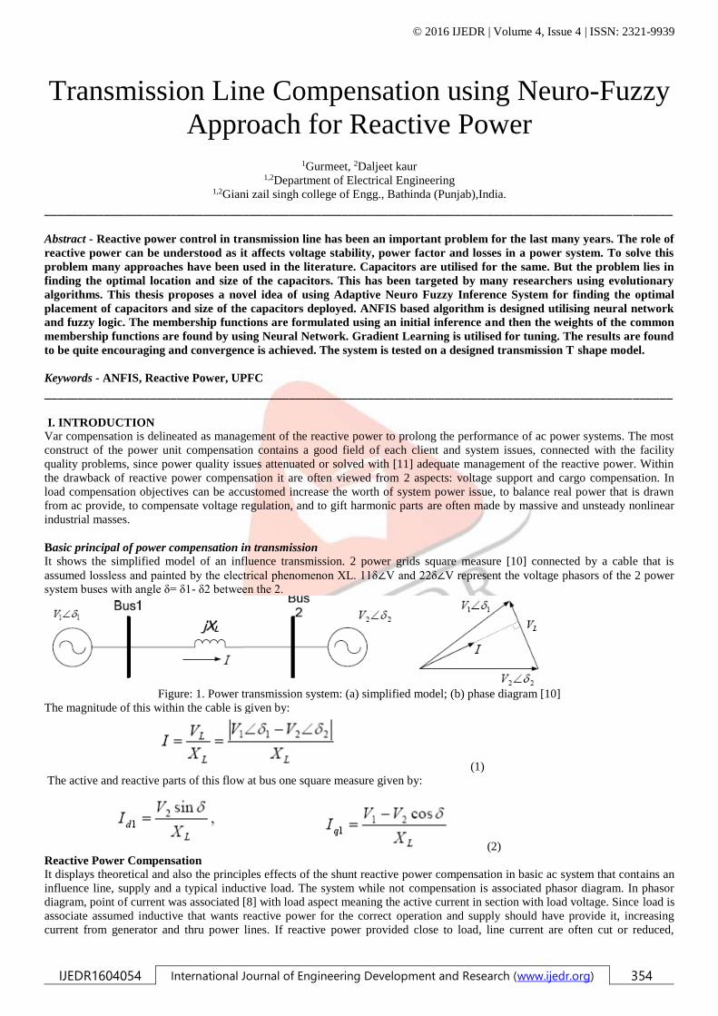
Basic principal of power compensation in transmission
It shows the simplified model of an influence transmission. 2 power grids square measure [10] connected by a cable that is
assumed lossless and painted by the electrical phenomenon XL. 11δ∠V and 22δ∠V represent the voltage phasors of the 2 power
system buses with angle δ= δ1- δ2 between the 2.
Figure: 1. Power transmission system: (a) simplified model; (b) phase diagram [10]
The magnitude of this within the cable is given by:
(1)
The active and reactive parts of this flow at bus one square measure given by:
(2)
Reactive Power Compensation It displays theoretical and also the principles effects of the shunt reactive power compensation in basic ac system that contains an
influence line, supply and a typical inductive load. The system while not compensation is associated phasor diagram. In phasor
diagram, point of current was associated [8] with load aspect meaning the active current in section with load voltage. Since load is
associate assumed inductive that wants reactive power for the correct operation and supply should have provide it, increasing
current from generator and thru power lines. If reactive power provided close to load, line current are often cut or reduced,
© 2016 IJEDR | Volume 4, Issue 4 | ISSN: 2321-9939
IJEDR1604054 International Journal of Engineering Development and Research (www.ijedr.org) 355
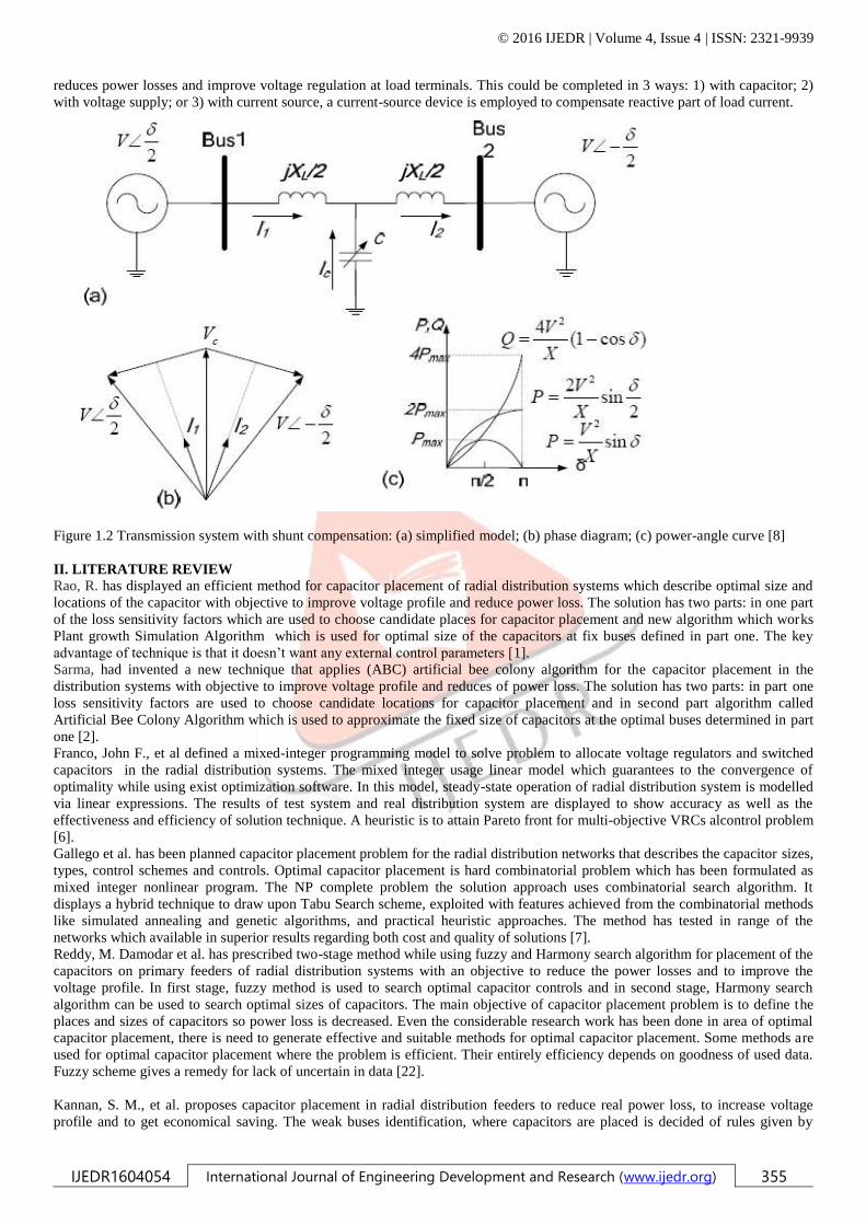
reduces power losses and improve voltage regulation at load terminals. This could be completed in 3 ways: 1) with capacitor; 2)
with voltage supply; or 3) with current source, a current-source device is employed to compensate reactive part of load current.
Figure 1.2 Transmission system with shunt compensation: (a) simplified model; (b) phase diagram; (c) power-angle curve [8]
II. LITERATURE REVIEW
Rao, R. has displayed an efficient method for capacitor placement of radial distribution systems which describe optimal size and
locations of the capacitor with objective to improve voltage profile and reduce power loss. The solution has two parts: in one part
of the loss sensitivity factors which are used to choose candidate places for capacitor placement and new algorithm which works
Plant growth Simulation Algorithm which is used for optimal size of the capacitors at fix buses defined in part one. The key
advantage of technique is that it doesn’t want any external control parameters [1].
Sarma, had invented a new technique that applies (ABC) artificial bee colony algorithm for the capacitor placement in the
distribution systems with objective to improve voltage profile and reduces of power loss. The solution has two parts: in part one
loss sensitivity factors are used to choose candidate locations for capacitor placement and in second part algorithm called
Artificial Bee Colony Algorithm which is used to approximate the fixed size of capacitors at the optimal buses determined in part
one [2].
Franco, John F., et al defined a mixed-integer programming model to solve problem to allocate voltage regulators and switched
capacitors in the radial distribution systems. The mixed integer usage linear model which guarantees to the convergence of
optimality while using exist optimization software. In this model, steady-state operation of radial distribution system is modelled
via linear expressions. The results of test system and real distribution system are displayed to show accuracy as well as the
effectiveness and efficiency of solution technique. A heuristic is to attain Pareto front for multi-objective VRCs alcontrol problem
[6].
Gallego et al. has been planned capacitor placement problem for the radial distribution networks that describes the capacitor sizes,
types, control schemes and controls. Optimal capacitor placement is hard combinatorial problem which has been formulated as
mixed integer nonlinear program. The NP complete problem the solution approach uses combinatorial search algorithm. It
displays a hybrid technique to draw upon Tabu Search scheme, exploited with features achieved from the combinatorial methods
like simulated annealing and genetic algorithms, and practical heuristic approaches. The method has tested in range of the
networks which available in superior results regarding both cost and quality of solutions [7].
Reddy, M. Damodar et al. has prescribed two-stage method while using fuzzy and Harmony search algorithm for placement of the
capacitors on primary feeders of radial distribution systems with an objective to reduce the power losses and to improve the
voltage profile. In first stage, fuzzy method is used to search optimal capacitor controls and in second stage, Harmony search
algorithm can be used to search optimal sizes of capacitors. The main objective of capacitor placement problem is to define the
places and sizes of capacitors so power loss is decreased. Even the considerable research work has been done in area of optimal
capacitor placement, there is need to generate effective and suitable methods for optimal capacitor placement. Some methods are
used for optimal capacitor placement where the problem is efficient. Their entirely efficiency depends on goodness of used data.
Fuzzy scheme gives a remedy for lack of uncertain in data [22].
Kannan, S. M., et al. proposes capacitor placement in radial distribution feeders to reduce real power loss, to increase voltage
profile and to get economical saving. The weak buses identification, where capacitors are placed is decided of rules given by

© 2016 IJEDR | Volume 4, Issue 4 | ISSN: 2321-9939
IJEDR1604054 International Journal of Engineering Development and Research (www.ijedr.org) 356
fuzzy expert system. Node voltage and power loss indices are used as inputs to fuzzy expert system and output is index sensitivity
that gives weak buses in system where capacitor to be placed. The size of capacitors is modelled by objective function to attain
the maximum savings while using the Multi Agent Particle Swarm Optimization and Differential Evolution. To consider the
applicability of algorithms, the simulation is displayed on existing IEEE 34 bus and 15 bus distribution feeders. The conclusion of
these approaches is compared with HPSO, PSO techniques and with results [8].
Sirjani, Reza et al. has been defined the power systems capacitors which are used to transfer reactive power to decrease loss and
to increase the voltage profile. The optimal placement of capacitors is important to ensure the system total capacitor costs and
power losses are minimal. This capacitor placement problem has solved using the heuristic optimization methods that are diverse
and subject of ongoing enhancements. It displays a survey of literature from last decade which has focused on several heuristic
optimization schemes applied to define the optimal capacitor placement and size. To decrease shunt capacitors, power loss that
are installed in power distribution networks, which are used to compensate for the reactive power. Though, the installation of the
shunt capacitors in distribution networks needs consideration of their optimal size and control. Capacitor placement is crucial to
increase loss reduction by installing shunt capacitors while decreasing shunt capacitor costs [28].
Reddy, V. U. has discussed about the electricity which is not only become a necessity but also tool to determine economic growth
and standing of a nation. The growth of exponential in demand over two decades and widening space between demands or supply
is growing concern. So reducing the gap, in addition to include new creating units, automation technology employed to reduce the
T&D losses and thus increases necessity of efficient and fast algorithms [9].
Kansal, Satish et al. has proposed an optimal placement of individual types of DGs which has been proposed. The optimal size
and locations of DG’s have defined to minimize power distribution loss. The power factor for DG supplying, both reactive and
real power, has been attained in work. Individual types of DGs are supplying reactive and real power at individual bus has been
considered in approach [10].
Franco, John F., et al defined a mixed-integer programming model to solve problem to allocate voltage regulators and switched
capacitors in the radial distribution systems. The mixed integer usage linear model which guarantees to the convergence of
optimality while using exist optimization software. In this model, steady-state operation of radial distribution system is modelled
via linear expressions. [11].
Gallego et al. has been planned capacitor placement problem for the radial distribution networks that describes the capacitor sizes,
types, control schemes and locations. Optimal capacitor placement is hard combinatorial problem which has been formulated as
mixed integer nonlinear program. The NP complete problem the solution approach uses combinatorial search algorithm. The
method has tested in range of the networks which available in superior results regarding both cost and quality of solutions [12].
III. PROBLEM FORMULATION
The objective of this paper is to solve the problem of reactive power compensation in transmission line to improve its
performance. Even though considerable amount of research work was done in the area of optimal capacitor placement, there is
still a need to develop more suitable and effective methods for the optimal capacitor placement. Although some of these methods
to solve capacitor allocation problem are efficient, their efficacy relies entirely on the goodness of the data used.
The objective of capacitor placement in the distribution system is to minimize the cost of the system, subjected to certain
operating constraints and load pattern. The three-phase system is considered as balanced and loads are assumed as time invariant.
Mathematically, the objective function of the problem is given as:
min f = min(COST)
where COST is the objective function which includes the cost of power loss and the capacitor placement. The voltage magnitude
at each bus must be maintained within its limits as:
≤ │Vi│≤
where is the voltage magnitude of bus i, and are bus minimum and maximum voltage limits respectively.
The problem of optimal allocation of the capacitor unit is formulated in the form of an optimisation problem. A cost function
considering the voltage and the real power loss in the transmission line is formed.
OBJECTIVES
The objectives of this thesis can be described as follows:
• Designing of a Transmission Line model
• Application of Reactive Power in the transmission line model
• Using Neuro-Fuzzy approach to control the FACTS
• Comparative analysis on the basis of power, voltage, current and power factor.
IV. PROPOSED METHODOLOGY
The objective of this thesis is to minimize the losses in the line by adding additional units of capacitors. The additional unit will
cater to the increased load demand. An objective function is formed depending on the line losses and the voltage profile.
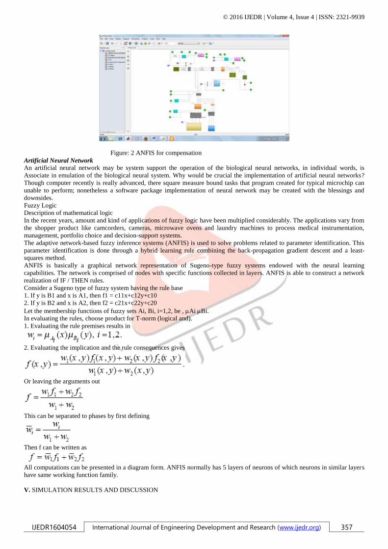
The complete model using ANFIS for compensation of transmission line is described below.
© 2016 IJEDR | Volume 4, Issue 4 | ISSN: 2321-9939
IJEDR1604054 International Journal of Engineering Development and Research (www.ijedr.org) 357
Figure: 2 ANFIS for compensation
Artificial Neural Network
An artificial neural network may be system support the operation of the biological neural networks, in individual words, is
Associate in emulation of the biological neural system. Why would be crucial the implementation of artificial neural networks?
Though computer recently is really advanced, there square measure bound tasks that program created for typical microchip can
unable to perform; nonetheless a software package implementation of neural network may be created with the blessings and
downsides.
Fuzzy Logic
Description of mathematical logic
In the recent years, amount and kind of applications of fuzzy logic have been multiplied considerably. The applications vary from
the shopper product like camcorders, cameras, microwave ovens and laundry machines to process medical instrumentation,
management, portfolio choice and decision-support systems.
The adaptive network-based fuzzy inference systems (ANFIS) is used to solve problems related to parameter identification. This
parameter identification is done through a hybrid learning rule combining the back-propagation gradient descent and a least-
squares method.
ANFIS is basically a graphical network representation of Sugeno-type fuzzy systems endowed with the neural learning
capabilities. The network is comprised of nodes with specific functions collected in layers. ANFIS is able to construct a network
realization of IF / THEN rules.
Consider a Sugeno type of fuzzy system having the rule base
1. If y is B1 and x is A1, then f1 = c11x+c12y+c10
2. If y is B2 and x is A2, then f2 = c21x+c22y+c20
Let the membership functions of fuzzy sets Ai, Bi, i=1,2, be , Ai Bi.
In evaluating the rules, choose product for T-norm (logical and).
1. Evaluating the rule premises results in
2. Evaluating the implication and the rule consequences gives
Or leaving the arguments out
This can be separated to phases by first defining
Then f can be written as
All computations can be presented in a diagram form. ANFIS normally has 5 layers of neurons of which neurons in similar layers
have same working function family.
V. SIMULATION RESULTS AND DISCUSSION
© 2016 IJEDR | Volume 4, Issue 4 | ISSN: 2321-9939
IJEDR1604054 International Journal of Engineering Development and Research (www.ijedr.org) 358
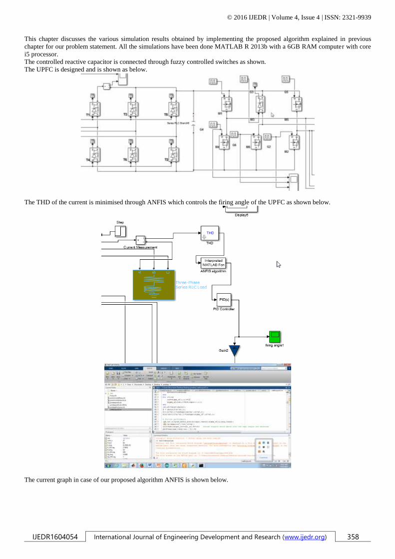
This chapter discusses the various simulation results obtained by implementing the proposed algorithm explained in previous
chapter for our problem statement. All the simulations have been done MATLAB R 2013b with a 6GB RAM computer with core
i5 processor.
The controlled reactive capacitor is connected through fuzzy controlled switches as shown.
The UPFC is designed and is shown as below.
The THD of the current is minimised through ANFIS which controls the firing angle of the UPFC as shown below.
The current graph in case of our proposed algorithm ANFIS is shown below.
© 2016 IJEDR | Volume 4, Issue 4 | ISSN: 2321-9939
IJEDR1604054 International Journal of Engineering Development and Research (www.ijedr.org) 359
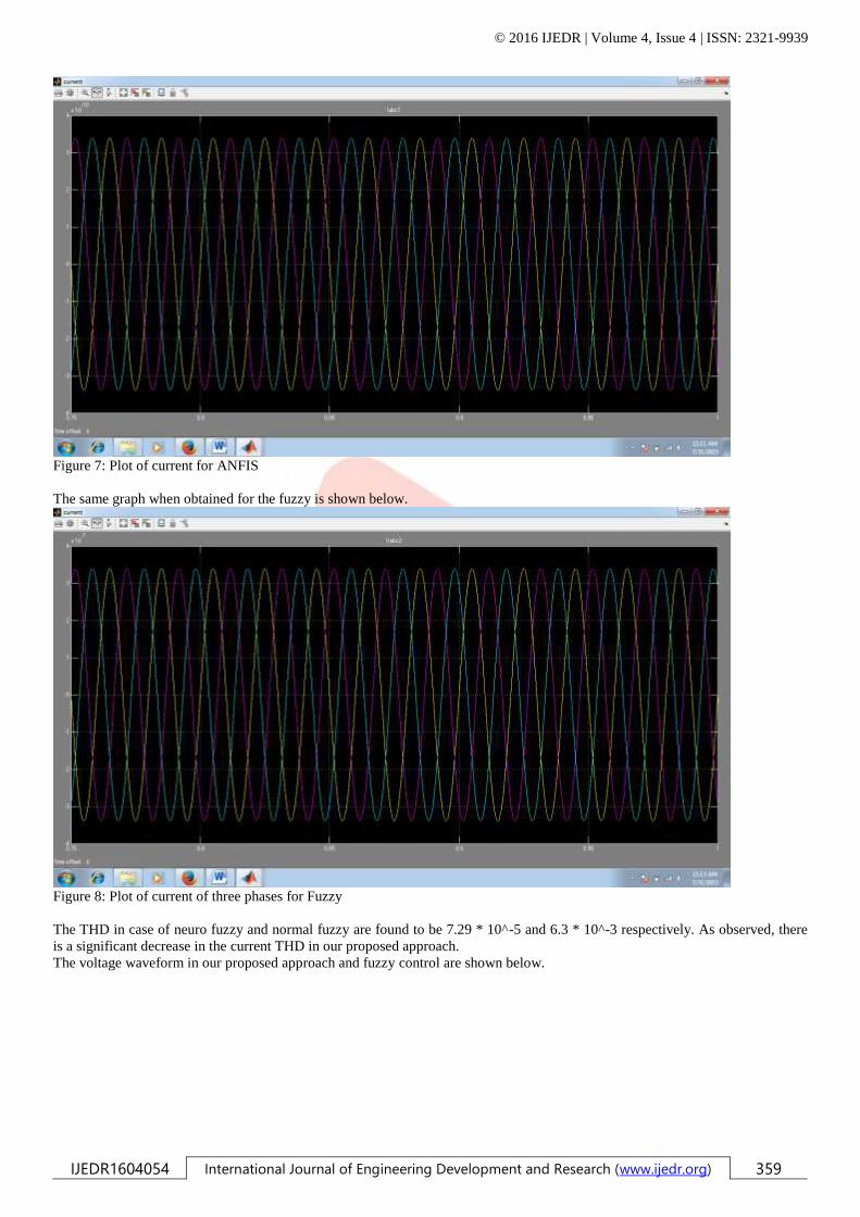
Figure 7: Plot of current for ANFIS
The same graph when obtained for the fuzzy is shown below.
Figure 8: Plot of current of three phases for Fuzzy
The THD in case of neuro fuzzy and normal fuzzy are found to be 7.29 * 10^-5 and 6.3 * 10^-3 respectively. As observed, there
is a significant decrease in the current THD in our proposed approach.
The voltage waveform in our proposed approach and fuzzy control are shown below.
© 2016 IJEDR | Volume 4, Issue 4 | ISSN: 2321-9939
IJEDR1604054 International Journal of Engineering Development and Research (www.ijedr.org) 360
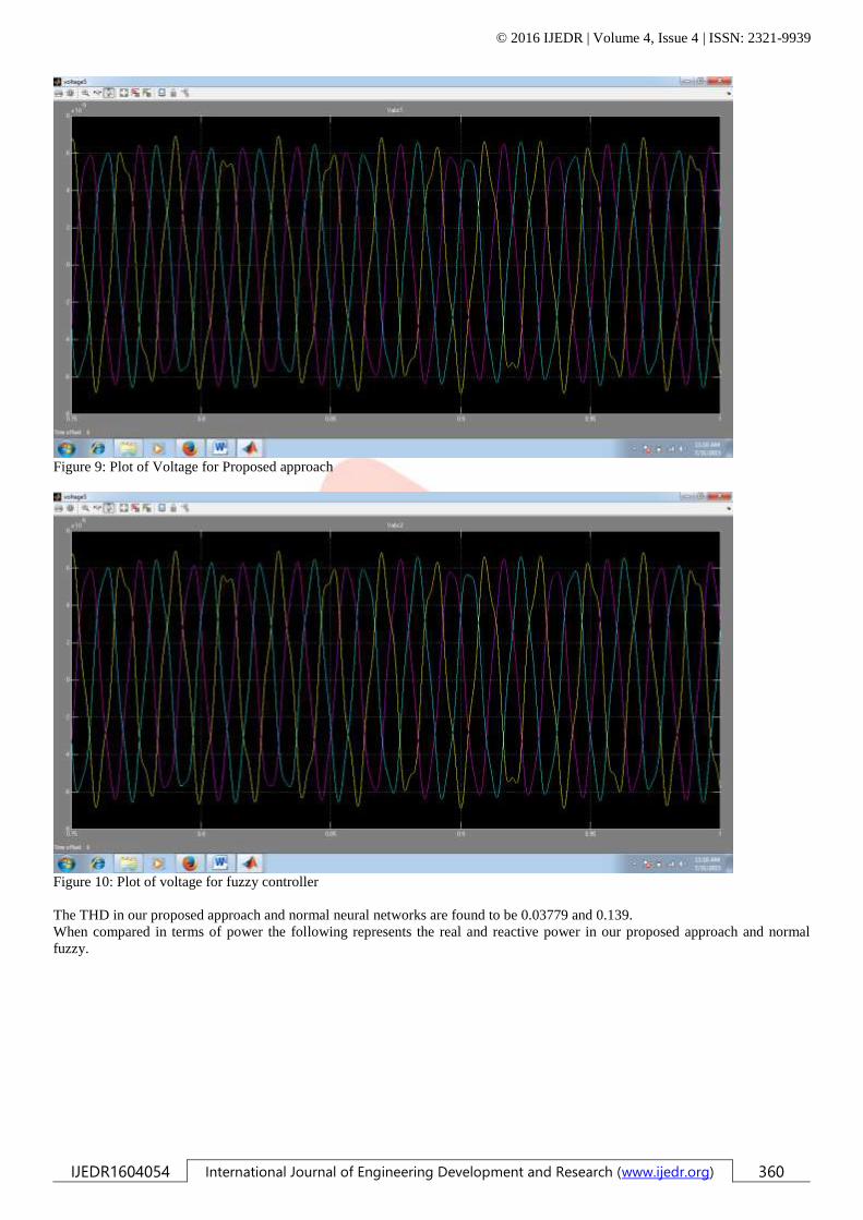
Figure 9: Plot of Voltage for Proposed approach
Figure 10: Plot of voltage for fuzzy controller
The THD in our proposed approach and normal neural networks are found to be 0.03779 and 0.139.
When compared in terms of power the following represents the real and reactive power in our proposed approach and normal
fuzzy.
© 2016 IJEDR | Volume 4, Issue 4 | ISSN: 2321-9939
IJEDR1604054 International Journal of Engineering Development and Research (www.ijedr.org) 361
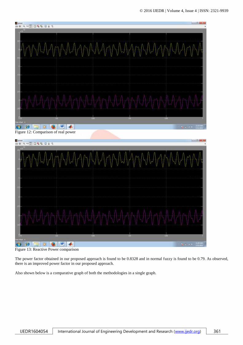
Figure 12: Comparison of real power
Figure 13: Reactive Power comparison
The power factor obtained in our proposed approach is found to be 0.8328 and in normal fuzzy is found to be 0.79. As observed,
there is an improved power factor in our proposed approach.
Also shown below is a comparative graph of both the methodologies in a single graph.
© 2016 IJEDR | Volume 4, Issue 4 | ISSN: 2321-9939
IJEDR1604054 International Journal of Engineering Development and Research (www.ijedr.org) 362
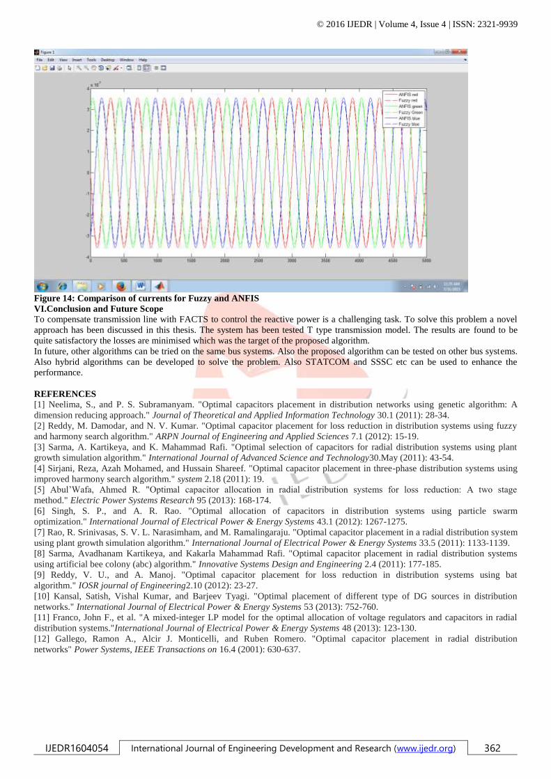
Figure 14: Comparison of currents for Fuzzy and ANFIS
VI.Conclusion and Future Scope
To compensate transmission line with FACTS to control the reactive power is a challenging task. To solve this problem a novel
approach has been discussed in this thesis. The system has been tested T type transmission model. The results are found to be
quite satisfactory the losses are minimised which was the target of the proposed algorithm.
In future, other algorithms can be tried on the same bus systems. Also the proposed algorithm can be tested on other bus systems.
Also hybrid algorithms can be developed to solve the problem. Also STATCOM and SSSC etc can be used to enhance the
performance.
REFERENCES
[1] Neelima, S., and P. S. Subramanyam. "Optimal capacitors placement in distribution networks using genetic algorithm: A
dimension reducing approach." Journal of Theoretical and Applied Information Technology 30.1 (2011): 28-34.
[2] Reddy, M. Damodar, and N. V. Kumar. "Optimal capacitor placement for loss reduction in distribution systems using fuzzy
and harmony search algorithm." ARPN Journal of Engineering and Applied Sciences 7.1 (2012): 15-19.
[3] Sarma, A. Kartikeya, and K. Mahammad Rafi. "Optimal selection of capacitors for radial distribution systems using plant
growth simulation algorithm." International Journal of Advanced Science and Technology30.May (2011): 43-54.
[4] Sirjani, Reza, Azah Mohamed, and Hussain Shareef. "Optimal capacitor placement in three-phase distribution systems using
improved harmony search algorithm." system 2.18 (2011): 19.
[5] Abul’Wafa, Ahmed R. "Optimal capacitor allocation in radial distribution systems for loss reduction: A two stage
method." Electric Power Systems Research 95 (2013): 168-174.
[6] Singh, S. P., and A. R. Rao. "Optimal allocation of capacitors in distribution systems using particle swarm
optimization." International Journal of Electrical Power & Energy Systems 43.1 (2012): 1267-1275.
[7] Rao, R. Srinivasas, S. V. L. Narasimham, and M. Ramalingaraju. "Optimal capacitor placement in a radial distribution system
using plant growth simulation algorithm." International Journal of Electrical Power & Energy Systems 33.5 (2011): 1133-1139.
[8] Sarma, Avadhanam Kartikeya, and Kakarla Mahammad Rafi. "Optimal capacitor placement in radial distribution systems
using artificial bee colony (abc) algorithm." Innovative Systems Design and Engineering 2.4 (2011): 177-185.
[9] Reddy, V. U., and A. Manoj. "Optimal capacitor placement for loss reduction in distribution systems using bat
algorithm." IOSR journal of Engineering2.10 (2012): 23-27.
[10] Kansal, Satish, Vishal Kumar, and Barjeev Tyagi. "Optimal placement of different type of DG sources in distribution
networks." International Journal of Electrical Power & Energy Systems 53 (2013): 752-760.
[11] Franco, John F., et al. "A mixed-integer LP model for the optimal allocation of voltage regulators and capacitors in radial
distribution systems."International Journal of Electrical Power & Energy Systems 48 (2013): 123-130.
[12] Gallego, Ramon A., Alcir J. Monticelli, and Ruben Romero. "Optimal capacitor placement in radial distribution
networks" Power Systems, IEEE Transactions on 16.4 (2001): 630-637.


![ABB_Distance Relay REL511-C1-Application Manual [ With Parallel Line Compensation Derivation]](https://img.pdfslide.net/doc/110x75/55720668497959fc0b8b8ffb/abbdistance-relay-rel511-c1-application-manual-with-parallel-line-compensation-derivation.jpg)