Embed Size (px)
Citation preview
POWER SYSTEM
CONTROL AND LINE
COMPENSATION
Submitted by Roll no. 1120810(E-6)and 1120508 (E-2)
CONTENTS:- Introduction Voltage control Power system control Control of reactive power and power factor Interconnected control and frequency ties Supervisory control Line compensation Series compensation Series and shunt compensation schemes for ac transmission system
Introduction
Power system control and line compensation are essential for the effective working of power system.
Voltage ,frequency and power factor are the main items to be controlled. To get the desired voltage at the consumer end voltage control is
necessary. Frequency control is done to form a synchronous link between two
systems having different frequencies. The control of reactive vars will automatically control the power factor of
the system. Nowadays Supervisory control for the power system is done from the
main control room.
Voltage Control
The voltage control in power system is necessary mainly in the following stages.
1. Generating end.2. Transmission lines.3. Receiving end.

Generating End Voltage Control Methods
Regulators using magnetic amplifiers
Electronic voltage regulators
Amplidyne control
Transistor voltage regulator
Thyristor automatic voltage regulator

SMALL DESCRIPTION ABOUT THE MODERN VOLTAGE REGULATORS USED FOR CONTROLLING ALTERNATOR VOLTAGE.
REGULATORS USING MAGNETIC AMPLIFIERS:> If the output voltage of the alternator changes to a value other than the reference value then the ampere turns of the control winding (combination of two dc windings arranged in opposition on the core to have opposing magnetic field effects) changes which changes the field current of exciter of alternator to maintain the constant output voltage.
ELECTRONIC VOLTAGE REGULATORS:> It consists of bridge circuit with thyratron valves which control the field of exciter.
AMPLIDYNE CONTROL:> Exciter field current of the alternator is controlled using amplidyne.
TRANSISTOR VOLTAGE REGULATOR:> Transistorised circuitary is used for the field current control.
THYRISTOR AUTOMATIC VOLTAGE REGULATOR:> These are the completely static voltage regulators having very fast response and they use high current thyristors.
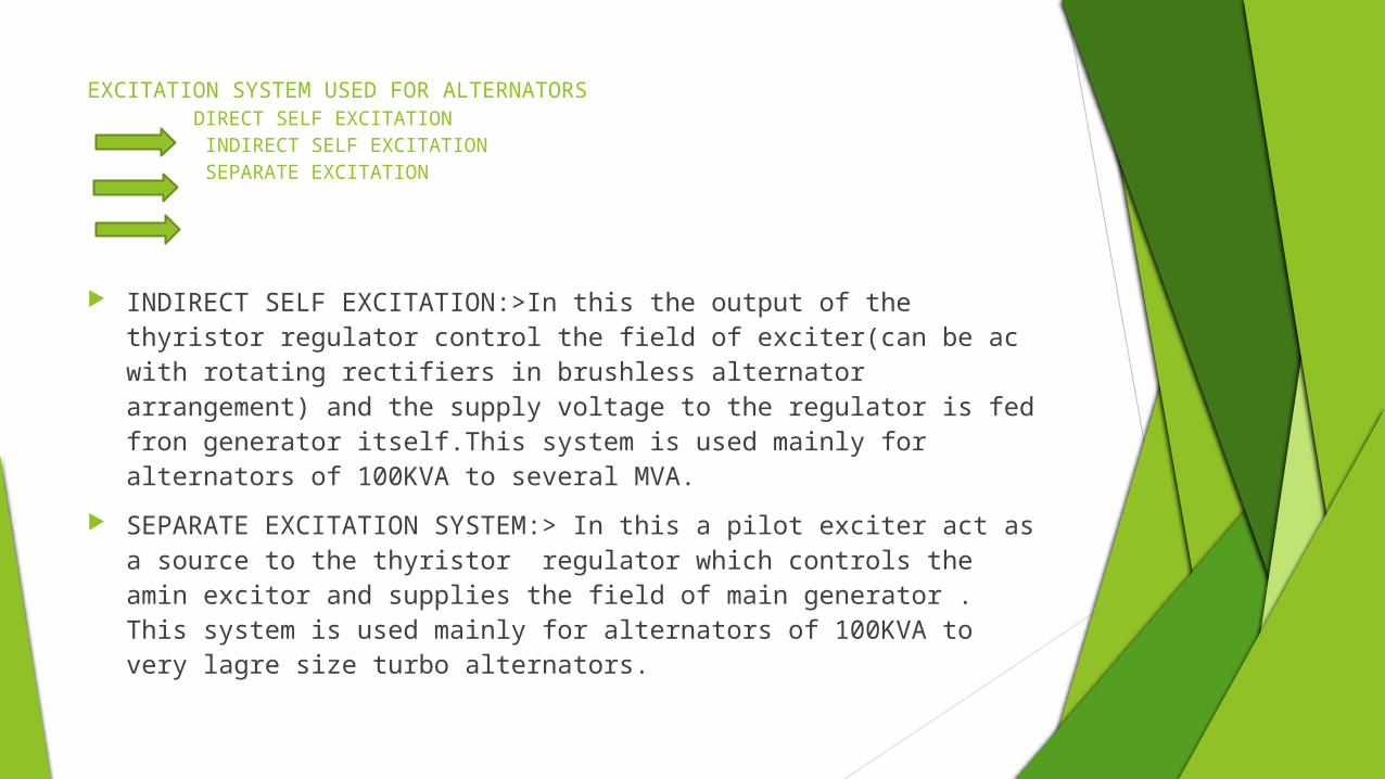
EXCITATION SYSTEM USED FOR ALTERNATORS DIRECT SELF EXCITATION INDIRECT SELF EXCITATION SEPARATE EXCITATION
INDIRECT SELF EXCITATION:>In this the output of the thyristor regulator control the field of exciter(can be ac with rotating rectifiers in brushless alternator arrangement) and the supply voltage to the regulator is fed fron generator itself.This system is used mainly for alternators of 100KVA to several MVA.
SEPARATE EXCITATION SYSTEM:> In this a pilot exciter act as a source to the thyristor regulator which controls the amin excitor and supplies the field of main generator . This system is used mainly for alternators of 100KVA to very lagre size turbo alternators.


VOLTAGE REGULATION OF TRANSMISSION LINEMethods used for regulation of T-line is as follows:
TAP CHANGING TRANSFORMERS:> Voltage level at the substation or the load points can be adjusted to desired level on load as well as off load.
BOOSTER TRANSFORMER:> They are used to raise the potential at a point away from the main transformer and are having a capacity of 10% to 20% of that of main transformers.
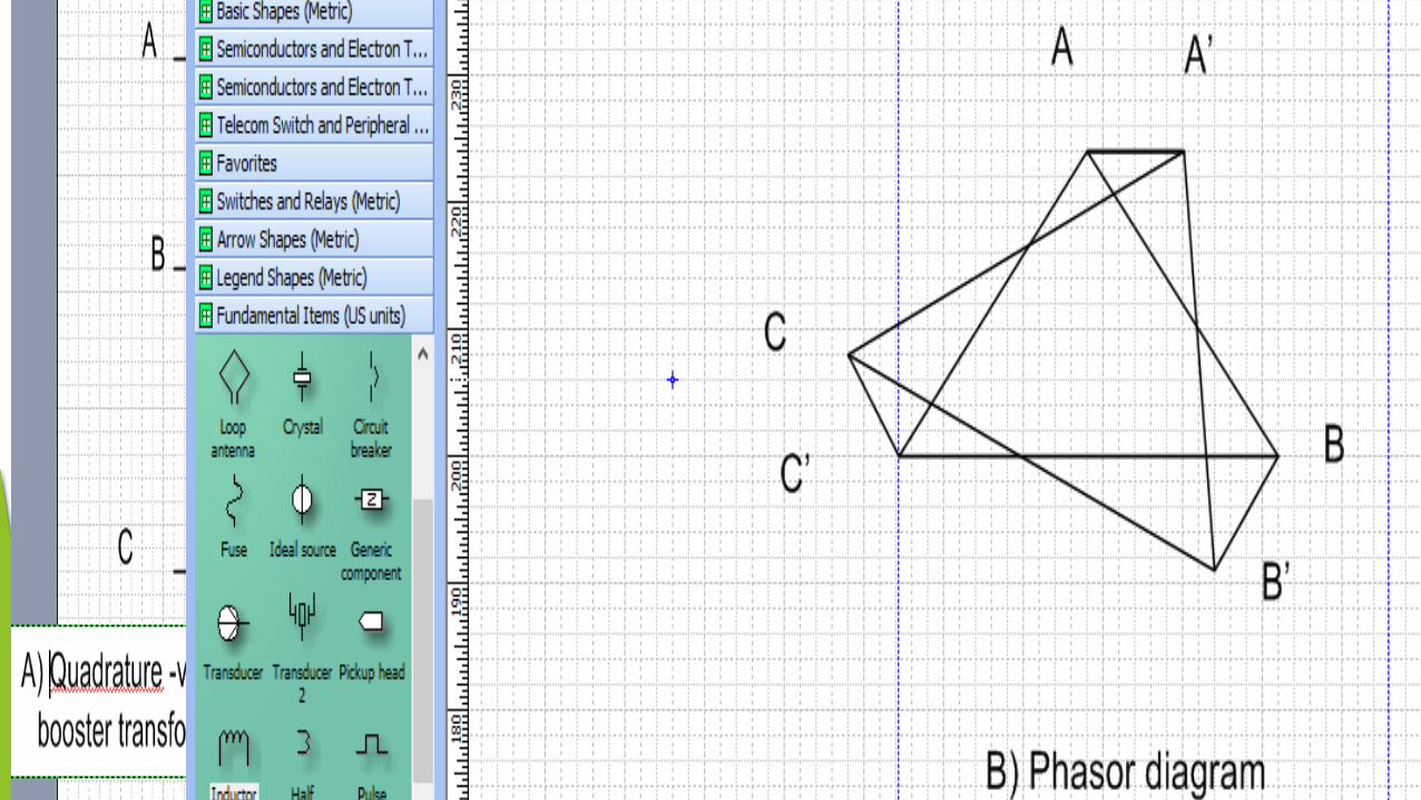
Selective load dispatching is necessary when stations in a systems are interconnected to avoid the overloading of lines which can be done using devices given below. IN PHASE VOLTAGE BOOSTER TRANSFORMER:>It is used to inject voltage in phase with the
line voltage. QUADRATURE VOLTAGE BOOSTER TRANSFORMER:>It is used to inject voltage at right angle
to the line voltage. INDUCTION REGULATOR:>This is similar to that of wound rotor induction motor in which the
rotor is not free to rotate and rotor winding is connected in series with the stator winding .


VOLTAGE REGULATION OF TRANSMISSION LINE
On Load Tap changing transformers Booster transformer
Phase shifting transformer Induction Regulator
Servo control Static voltage control
AUTOMATIC VOLTAGE CONTROL :> IT is affected by servo control having three principal elements
1.Voltage regulating relay.2.Intermediate relay.3.Motor drive.STATIC VOLTAGE CONTROL:>It is being used for high voltage transmission line upto 330 KV. The static network compensator employ ac saturating reactor for the reactive power control and can be used in conjunction with the static compensator which have following advantages:o Instantaneous overvoltage prevention.o Prevents loss of synchronism.o Increases the capacity of transmission line.o Increase in the stability limit.o Possibility to increase transmission line length increases.
POWER SYSTEM CONTROLThe main problems of control are : ACTIVE POWER LOAD FREQUENCY CONTROL. REACTIVE POWER VOLTAGE CONTROL.
Methods used for solving both the problems are as follows: PF CONTROL :>This helps in controlling the frequency and real power
exchange through the outgoing lines. QV CONTROL:>This helps in controlling the voltage |Vi|. AUTOMATIC LOAD FREQUENCY CONTROL:>This is used to control the
real power output of generators within a prescribed area in response to changes in system frequency and line loadings in order to maintain the system frequency and interchange of power .

CONTROL OF REACTIVE POWER AND POWER FACTOR REACTIVE POWER CONTROL:>Interconnector transformers are used for the
var interchange in the power system. When the taps of transformers are changed in the ring main circulatory current flows through it so the var distribution is affected with the condition that reactance to resistance ratio should be high for the ring circuit otherwise active power distribution will be there.
POWER FACTOR CONTROL:>Power factor can be controlled by following ways:
1)SYNCHRONUS MACHINES- When they are run as overexcited synchronous motor they supply leading reactive KVA to improve the p.f and hence the voltage regulation of the system. When operated on no load only for p.f correction they are called as synchronous compensators.2)PHASE ADVANCERS- For improving the p.f of industrial motors Lebano exciter and Scherbius type phase advancers are used.3)SHUNT CAPACITORS- Its corrective capacity is the square of applied voltage & varies directly as the frequency and their capacity can be varied only by changing the no. of units. They are located near the induction motor apparatus and power losses are low as compared to other methods used. Also they can’t be used at full load and no load for efficient operation.

4) SERIES CAPACITORS- They are used to reduce the reactance between source and distribution location so gives a better voltage regulation on lagging power factor loads and to give better power transfer. A gap along with a C.B is set in parallel to flashover when the voltage increases 2-4 times the normal rated value.

INTERCONNECTOR CONTROL Interconnection of power station is done to have the reliability and also power transfer can be
done from any station depending on the requirement. Some stations can run at unity p.f and some at lagging p.f giving the reactive power. A large change in load change the phase angle of one station w.r.t other which results in the
flow of synchronising power. When the resistance and reactance of interconnector are numerically equal the synchronising
power becomes maximum. Power flow through the interconnector is proportional to its reactance and share the total load
in proportion to their impedance value. Load sharing trough interconnector are done by in phase and quadrature voltage control.
FREQUENCY TIES Frequency ties which are the form of frequency convertors are required when the systems of
different frequencies are to be tied together. Frequency ties are of following types:1)A SYNCHRONUS MOTOR – SYNCHRONUS ALTERNATOR SET :It forms a rigid frequency tie between the two systems and the load over each set is controlled by adjusting input the prime mover at the stations.2) AN INDUCTION MOTOR – SYNCHRONUS ALTERNATOR SET : It do not form a rigid frequency tie between the two system but as load varies frequency also vary owing to slip of induction motor.3) SYNCHRONUS CONVERTOR SET – It consists of two rotary convertor operated in series .First one converts ac to dc supply and the second dc to ac of the frequency of second power system . Load control can be arranged at convertor and it has wide range of frequency ratio.4)DC LINK – Large power system with the different frequencies can be interconnected using high power rectifiers at each end and the dc link in between them . The dc link do not carry do not carry wattles power or reactive power from one system to another.

SUPERVISORY CONTROL It is defined as control of electrical apparatus from the place other than apparatus installed. It enables the remote control of apparatus, indicates the position –ON/OFF, enables to transmit
metering at various distant substations to be controlled. It may use the pilot wires or telephone channels or carrier current or microwave radio for
transmitting information and operating switches. Operation performed by supervisory control may be opening and closing of C.B and isolators ,
indication of C.B operation, transformer tap changing, telemetering indicating metre readings centrally by transferring information from various substations, showing the position of water intake gates, starting equipments , speed and excitation control etc.
Its applications results in advantages in the manual operation and in unattended automatic stations. It helps in maintaining services, under emergency conditions , by giving the operator a complete picture of entire system at all the times.
LINE COMPENSATION Long distance EHV(extra high voltage) ac transmission system
require the use of series capacitors and shunt reactors to artificially reduce the series reactance and shunt susceptance of the lines and act as line compensation.
Their use results in improving the system stability and voltage control ,in increasing the efficiency of power transmission , facilititating line energisation and reducing temporary and transient overvoltages.

Line compensation Advantages
This is done to control the reactive var flow control. The advantages of using line compensation methods in the power
system are Power transmission capability is increased Power factor of the system is improved. The voltage regulation is minimum.

Types of line compensation
There are two types of line compensation• Series compensation• Shunt compensation

Series compensation
Series capacitors are used to increase the transmission capability and they are economical for distances less than 300km.
P=(V*V)/(Xl-Xc) where P means power transmitted, Xl is the inductive reactance and Xc is the capacitive reactance.
Hence as Xc increases implies P increases. To achieve surge impedance loading switching of the capacitive
banks is done.
Shunt compensation To compensate a shunt capacitor is connected which draws current leading the source voltage.
The net results in improvement of power factor.
Shunt inductors are used when there is a requirement of supply of leading vars in the power system.
It improves the damping to power oscillations.

Series & Shunt Compensation Schemes for ac Transmission Systems There can be a number of arrangements of connecting capacitors and
reactors in the system for compensation.
The assumptions made are :1) The capacitor banks and reactors are not more than two per line section,2) the capacitors are located at line section ends or at the midpoints and the reactors are located at section ends.

Comparative Examination of Compensation Effectiveness of the symmetrical schemes
Evaluation of compensation effectiveness can be made in two ways:-1) For assigned total Mvars of series capacitors and shunt
reactors ,determine the transmission capabilities at the stability limit of the systems differing only by compensation schemes;
2) For an assigned transmission capacity, determine the required Mvars of the series and shunt compensation for various schemes.

Modern practice: 3.1 STATCOM
Static Synchronous Compensator (STATCOM) is a part of the Flexible Alternating Current Transmission systems (FACTS) device family. They are fast acting, precise, and adjustable amount of reactive power to the ac power system to which they are connected.
STATCOMs can be used for Voltage regulation at the receiver end of ac transmission lines, thus replacing banks of shunt capacitors. When used for this purpose, STATCOMs offer a number of advantages over banks of shunt capacitors, such as much tighter control of the voltage compensation at the receiver end of the ac transmission line and increased line stability during load variations.
STATCOMs are commonly used for dynamic power factor correction (i.e., dynamic reactive power compensation) in industrial plants operating with large random peaks of reactive power demand and also maintains the power Quality in premises. STACOMs increase the power factor of the plant, minimise the voltage fluctuations at the plant input (which prevents damage to the equipment), and reduce the plant’s operating costs.
References
1. M V Deshpande2. I.J Nagrath and Kothari3. C.L Wadhwa

{THANK YOU}


![Reactive Power Compensation[1]](https://img.pdfslide.net/doc/110x75/577ccf3f1a28ab9e788f40c0/reactive-power-compensation1.jpg)