Embed Size (px)
Citation preview

1200P4-Assy-3-07 Page 1 Copyright 2006 All Rights Reserved
Transportable VSAT System Assembly Instructions
1984 West New Hampshire Street Orlando, FL 32804 407.650.9054 1200P4-Assy-3-07 Copyright 2006 All Rights Reserved

1200P4-Assy-3-07 Page 2 Copyright 2006 All Rights Reserved
Contents
Page Removal from Case ......................................... 3 Reflector Assembly .......................................... 4 Boom Assembly ............................................... 6 Feed Attachment.............................................. 7 Pedestal Startup..............................................11 Mounting the Reflector................................... 13 Mount the Wedge Plate ................................. 14 Final Deployment ........................................... 16 Stowing .......................................................... 17 Dismantling the Reflector............................... 17 Dismantle the Feed/Boom ............................. 18 Stowing the Reflector ..................................... 21 Wedge Plate Removal ................................... 22 Stowing the Pedestal ..................................... 22 Pedestal Case Content Packaging ................ 28

1200P4-Assy-3-07 Page 3 Copyright 2006 All Rights Reserved
MVS1200P4 The case on the left is the pedestal—note the small side is at the bottom which is the heavier side. The case on the right contains the reflector, boom, feed as-sembly, support struts and cables.
MVS1200P4—Reflector Case Open the latches on the reflector case. Remove the lid and place on the ground.
MVS1200P4-Reflector Case Note placement of equipment / items.
ASSEMBLY
1
2
3

1200P4-Assy-3-07 Page 4 Copyright 2006 All Rights Reserved
MVS1200P4-Pedestal Case Bottom CAUTION—FRAGILE Remove the straps securing the Reflector Bags, and carefully set aside.
MVS1200P4-Reflector Numbers CAUTION—FRAGILE Note the numbers on edges of the reflector. Align the pieces as you place them on the ground.
MVS1200P4-Reflector Bags CAUTION—FRAGILE Carefully Remove the reflector panels from the bags. Shown at the left is the TOP sec-tion, the boom attaches to the bracket that is shown on the reflector.
4
5
6

1200P4-Assy-3-07 Page 5 Copyright 2006 All Rights Reserved
MVS1200P4-Reflector Numbers CAUTION—FRAGILE Align the pieces as you place them on the ground.
MVS1200P4-Reflector Numbers CAUTION—FRAGILE Align the snap buckles and secure the four sections together.
MVS1200P4—Boom Struts Remove the two boom struts from the bottom of the reflector case.
7
8
9

1200P4-Assy-3-07 Page 6 Copyright 2006 All Rights Reserved
MVS1200P4—Reflector Assembly Insert the boom into the boom bracket and secure with the boom clip.
MVS1200P4—Reflector Assembly Pull the spring loaded locking sleeve back and insert the strut onto the ball located on the side of the reflector. Secure both struts in this manner.
MVS1200P4—Reflector Assembly Pull the spring loaded locking sleeve back and insert the strut onto the ball located on the side of the feed horn plate.
10
11
12

1200P4-Assy-3-07 Page 7 Copyright 2006 All Rights Reserved
MVS1200P4—Reflector As-sembly Pull the spring loaded locking sleeve back and insert the strut onto the ball located on the side of the reflector. Secure both struts in this man-ner.
13
MVS1200P4—Reflector Case Carefully, remove the BUC and Feed Horn assembly from the Reflector Case. Remove the protective cover from the Feed Horn.
14
MVS1200P4—Reflector Case Loosen the locking adjustment on the Feed assembly.
15
NOTE: The FEED assembly is being shown WITHOUT the flexible waveguide and LNB to assist in clar-ity. In ALL cases, the unit will actu-ally appear as in Step 13.

1200P4-Assy-3-07 Page 8 Copyright 2006 All Rights Reserved
MVS1200P4—Reflector Case Rotate the assembly 90o so the assembly is oriented as in the picture. For the antenna to be able to communi-cate with the satellite, this rotation step is mandatory.
15
Operational Orientation
MVS1200P4—Reflector Case Tighten the locking adjustment on the Feed assembly.
16

1200P4-Assy-3-07 Page 9 Copyright 2006 All Rights Reserved
MVS1200P4—Pedestal Case Secure the BUC to the boom assembly using the captive mounting pins on the boom. Secure the front and back pins.
MVS1200P4—Pedestal Case Secure the feed horn assembly to the front of the boom using the captive mounting twist locks on the boom.
18
17

1200P4-Assy-3-07 Page 10 Copyright 2006 All Rights Reserved
MVS1200P4—Pedestal Case Using the RED color coded cable, secure the BUC wiring to the side of the BUC.
MVS1200P4—Pedestal Case Using the BLUE color coded cable, secure the LNB wiring to the end of the LNB.
MVS1200P4—Reflector & Boom The Reflector assembly is completed. You will need two people to assemble the reflector onto the pedestal.
19
20
21

1200P4-Assy-3-07 Page 11 Copyright 2006 All Rights Reserved
MVS1200P4—Pedestal Case Remove the lid of the Pedestal Case.
MVS1200P4—Pedestal Case Remove the WEDGE assembly from its storage posi-tion. Carefully set aside.
MVS1200P4—Reflector Case Remove the CONTROL CABLE bag from bottom of the REFLECTOR Case.
MVS1200P4—Pedestal Case Remove the OUTRIGGER supports from the side mounts on the lid of the pedestal case.
25
24
23
22

1200P4-Assy-3-07 Page 12 Copyright 2006 All Rights Reserved
MVS1200P4—Pedestal Case Secure the OUTRIGGERS to both ends of the pedestal case bottom.
MVS1200P4—Pedestal Case Secure the CABLES to the antenna, securing all three cables to the cable attachment bracket. RED—TRANSMIT BLUE—RECEIVE GREEN—Control Cable
27
26

1200P4-Assy-3-07 Page 13 Copyright 2006 All Rights Reserved
MVS1200P4—Equipment Case Secure the CABLES from the antenna to the equipment case, securing all three cables to the cable attachment plate. Note again: BLUE—RECEIVE RED—TRANSMIT GREEN—CONTROL
MVS1200P4—Equipment Case Apply POWER to the antenna.
MVS1200P4—Pedestal Deployment Deploy the antenna by Pressing the “+” button and holding down for 2 seconds.
MVS1200P4—Pedestal Deployment The pedestal will move to a reflector loading position and then stop. The display will show a Compass/Dish error as the reflector has not yet been mounted.
31
30
29
28

1200P4-Assy-3-07 Page 14 Copyright 2006 All Rights Reserved
MVS1200P4—Pedestal Case WEDGE PLATE Loosen the four captive bolt assemblies to al-low mounting of the wedge plate. Maneuver the wedge plate onto the pedestal POL drive plate. Once fitted over the four mounting screws, ro-tate the plate to align the locking pin hole in the wedge plate and the pedestal POL drive plate for alignment. Once aligned, insert the locking pin in place then securely tighten the four captive bolt as-semblies further locking the wedge plate to the pedestal.
MVS1200P4—Pedestal Case Mount the reflector to the pedestal. Align for the boom to be mounted to the TOP of the reflector. Set reflector mount point on mounting sup-port of wedge. Place reflector flat against the wedge plate.
33
32

1200P4-Assy-3-07 Page 15 Copyright 2006 All Rights Reserved
MVS1200P4—Pedestal Case Assembled BOOM.
MVS1200P4—Pedestal Case
Assembled antenna, from the rear.
MVS1200P4—Pedestal Case Secure the boom wiring to the pedestal.
MVS1200P4—Pedestal Case Secure the captive locking hardware fas-tening reflector to the pedestal.
36
35
34
1200P4-Assy-3-07 Page 16 Copyright 2006 All Rights Reserved
MVS1200P4—Pedestal Case Return to the Antenna Control panel. Press the “+” button to resume the de-ployment operation.
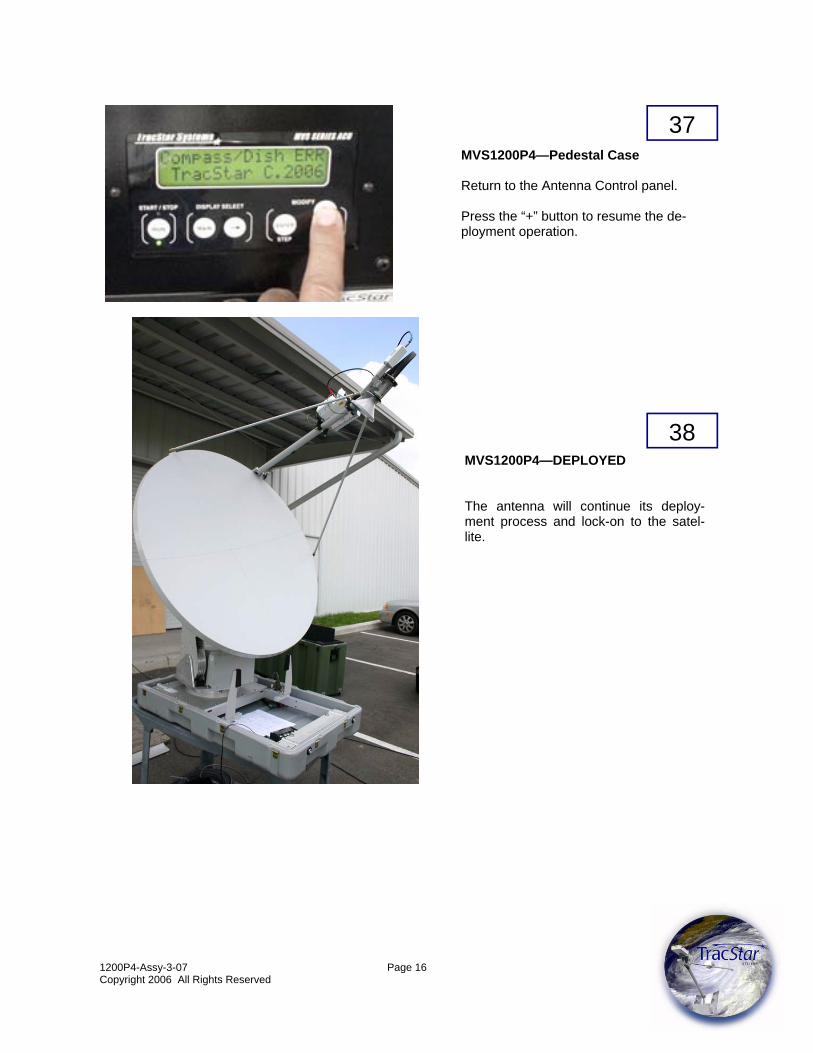
MVS1200P4—DEPLOYED The antenna will continue its deploy-ment process and lock-on to the satel-lite.
37
38

1200P4-Assy-3-07 Page 17 Copyright 2006 All Rights Reserved
DISASSEMBLY
MVS1200P4—STOWING Return to the Antenna Control panel. Press the “-” button to begin the stowing operation.
MVS1200P4—STOWING
The antenna will stop and display
REMOVE DISH
The disassembly process can begin.
42
41
40
39
MVS1200P4—DISMANTLE REFLECTOR Remove the boom wiring to the pedestal.
MVS1200P4—DISMANTLE REFLECTOR Unscrew the captive locking hardware fas-tening reflector to the pedestal.

1200P4-Assy-3-07 Page 18 Copyright 2006 All Rights Reserved
44
43 MVS1200P4—DISMANTLE REFLECTOR Remove the reflector from the pedestal and set it on the ground.
MVS1200P4—DISMANTLE REFLECTOR Using the RED color coded cable, remove the BUC wiring from the side of the BUC.
45 MVS1200P4—DISMANTLE REFLECTOR Using the BLUE color coded cable, remove the LNB wiring from the end of the LNB.

1200P4-Assy-3-07 Page 19 Copyright 2006 All Rights Reserved
MVS1200P4 — REFLECTOR CASE Replace cover on the feed horn. Carefully, place the BUC and Feed Horn assembly in the Reflector Case.
47
MVS1200P4—DISMANTLE REFLECTOR Remove the BUC from the boom assembly using the captive mounting pin on the boom. Remove the front and back pins.
46
MVS1200P4—DISMANTLE REFLECTOR Remove the feed horn assembly from the front of the boom using the captive mounting twist locks on the boom. Be careful not to damage the horn assembly.
48

1200P4-Assy-3-07 Page 20 Copyright 2006 All Rights Reserved
MVS1200P4—REFLECTOR DISASSEMBLY Remove the boom assembly support struts from the front of the boom pulling free from the cap-tive mounting ball on the boom. Remove the struts from the boom assembly.
50
MVS1200P4—REFLECTOR DISASSEMBLY Remove the boom from the boom bracket and secure the boom clip back in the bracket.
MVS1200P4—REFLECTOR DISASSEMBLY Pull the spring loaded locking sleeve back and remove the strut from the ball located on the side of the feed horn plate.
49
51

1200P4-Assy-3-07 Page 21 Copyright 2006 All Rights Reserved
MVS1200P4—REFLECTOR CASE Secure the two boom supports to the bottom of the reflector case.
MVS1200P4—REFLECTOR CASE Carefully separate the four reflector pan-els.
MVS1200P4—REFLECTOR CASE CAUTION—FRAGILE Loosen the snap locks.
52
54
53

1200P4-Assy-3-07 Page 22 Copyright 2006 All Rights Reserved
MVS1200P4—REFLECTOR CASE CAUTION—FRAGILE Carefully place the reflector in the contain-ment bags. As per picture at right, ensure the boom bracket is inserted AWAY from the second reflector panel in the bag.
MVS1200P4—REFLECTOR CASE WEDGE PLATE Disengage the locking pin from the wedge assembly. Loosen the four captive mounting screws, rotate the plate to align cut outs with screws and lift/remove the wedge assembly from the pedestal POL drive assembly.
55
56

1200P4-Assy-3-07 Page 23 Copyright 2006 All Rights Reserved
MVS1200P4—REFLECTOR CASE Secure the WEDGE assembly to its storage position.
MVS1200P4—REFLECTOR CASE Remove the OUTRIGGERS from both ends of the pedestal case bottom.
MVS1200P4—REFLECTOR CASE Secure the OUTRIGGER supports to the side mounts on the lid of the pedestal case.
MVS1200P4— PEDESTAL CASE DISMANTLE Return to the Antenna Controller. Press the “+” but-ton and hold down for 2 seconds. The STOW process will continue.
57
58
59
60

1200P4-Assy-3-07 Page 24 Copyright 2006 All Rights Reserved
MVS1200P4—PEDESTAL CASE Remove Power from the antenna.
MVS1200P4—PEDESTAL CASE Remove the cable assemblies from the antenna pedestal. Re-secure the protec-tive caps over the connections.
61
62
MVS1200P4—PEDESTAL CASE Loosen Feed adjustment assembly.
63

1200P4-Assy-3-07 Page 25 Copyright 2006 All Rights Reserved
MVS1200P4—REFLECTOR CASE Re-secure hardware to the ‘lid’ of the reflector case. See Last Page for detail layout.
66
64 MVS1200P4—PEDESTAL CASE Rotate the Feed to return it to its storage position.
65 MVS1200P4—PEDESTAL CASE Tighten the Feed assembly.

1200P4-Assy-3-07 Page 26 Copyright 2006 All Rights Reserved
MVS1200P4—REFLECTOR CASE Place antenna reflector bags into bottom of the reflec-tor case. Secure with the straps.
MVS1200P4—REFLECTOR CASE Return the control cable to the CONTROL CABLE bag and return to the bottom of the REFLECTOR Case.
MVS1200P4—REFLECTOR CASE Return lid to the reflector case and secure all latches.
MVS1200P4—REFLECTOR CASE Remove the CABLES from the equipment case. Coil and return to the bottom of the reflector case.
67
68
69
70

1200P4-Assy-3-07 Page 27 Copyright 2006 All Rights Reserved
MVS1200P4—PEDESTAL CASE Return the lid to the Pedestal Case and se-cure all latches.
MVS1200P4 The units are ready for transport. Be sure to return lids to auxiliary equipment case and check area for any loose equip-ment.
Alternate Power Configuration Power for the unit can be from a stan-dard AC power source OR from a DC battery in a vehicle. For standard AC, the plug shown at the lower left is removed from the inverter plug and plugged directly into the AC power source. This plug powers the power strip inside the case. When AC power is available, the cord lights indi-cate such and the equipment in the bot-tom of the rack will indicate the AC volt-age—e.g., 117 VAC as shown. During an absence of AC power, a spe-cial power cord is supplied that can con-nect the battery to the equipment rack. Once that is done, connecting the power cord to the Inverter as shown at left and flipping the switch on the Exeltech to ON, will provide AC Voltage to all equipment. Ensure the Inverter is OFF when not in use.
71
72

1200P4-Assy-3-07 Page 28 Copyright 2006 All Rights Reserved